EP3787901B1 - Authentifizierungsmechanismen - Google Patents
Authentifizierungsmechanismen Download PDFInfo
- Publication number
- EP3787901B1 EP3787901B1 EP18766571.6A EP18766571A EP3787901B1 EP 3787901 B1 EP3787901 B1 EP 3787901B1 EP 18766571 A EP18766571 A EP 18766571A EP 3787901 B1 EP3787901 B1 EP 3787901B1
- Authority
- EP
- European Patent Office
- Prior art keywords
- interface
- print particle
- mating interface
- dispense
- Prior art date
- Legal status (The legal status is an assumption and is not a legal conclusion. Google has not performed a legal analysis and makes no representation as to the accuracy of the status listed.)
- Active
Links
Images


Classifications
-
- B—PERFORMING OPERATIONS; TRANSPORTING
- B41—PRINTING; LINING MACHINES; TYPEWRITERS; STAMPS
- B41J—TYPEWRITERS; SELECTIVE PRINTING MECHANISMS, i.e. MECHANISMS PRINTING OTHERWISE THAN FROM A FORME; CORRECTION OF TYPOGRAPHICAL ERRORS
- B41J2/00—Typewriters or selective printing mechanisms characterised by the printing or marking process for which they are designed
- B41J2/005—Typewriters or selective printing mechanisms characterised by the printing or marking process for which they are designed characterised by bringing liquid or particles selectively into contact with a printing material
- B41J2/01—Ink jet
- B41J2/17—Ink jet characterised by ink handling
- B41J2/175—Ink supply systems ; Circuit parts therefor
- B41J2/17503—Ink cartridges
- B41J2/17506—Refilling of the cartridge
-
- B—PERFORMING OPERATIONS; TRANSPORTING
- B41—PRINTING; LINING MACHINES; TYPEWRITERS; STAMPS
- B41J—TYPEWRITERS; SELECTIVE PRINTING MECHANISMS, i.e. MECHANISMS PRINTING OTHERWISE THAN FROM A FORME; CORRECTION OF TYPOGRAPHICAL ERRORS
- B41J2/00—Typewriters or selective printing mechanisms characterised by the printing or marking process for which they are designed
- B41J2/005—Typewriters or selective printing mechanisms characterised by the printing or marking process for which they are designed characterised by bringing liquid or particles selectively into contact with a printing material
- B41J2/01—Ink jet
- B41J2/17—Ink jet characterised by ink handling
- B41J2/175—Ink supply systems ; Circuit parts therefor
- B41J2/17503—Ink cartridges
- B41J2/1752—Mounting within the printer
- B41J2/17523—Ink connection
-
- B—PERFORMING OPERATIONS; TRANSPORTING
- B41—PRINTING; LINING MACHINES; TYPEWRITERS; STAMPS
- B41J—TYPEWRITERS; SELECTIVE PRINTING MECHANISMS, i.e. MECHANISMS PRINTING OTHERWISE THAN FROM A FORME; CORRECTION OF TYPOGRAPHICAL ERRORS
- B41J2/00—Typewriters or selective printing mechanisms characterised by the printing or marking process for which they are designed
- B41J2/005—Typewriters or selective printing mechanisms characterised by the printing or marking process for which they are designed characterised by bringing liquid or particles selectively into contact with a printing material
- B41J2/01—Ink jet
- B41J2/17—Ink jet characterised by ink handling
- B41J2/175—Ink supply systems ; Circuit parts therefor
- B41J2/17503—Ink cartridges
- B41J2/17543—Cartridge presence detection or type identification
- B41J2/17546—Cartridge presence detection or type identification electronically
-
- B—PERFORMING OPERATIONS; TRANSPORTING
- B41—PRINTING; LINING MACHINES; TYPEWRITERS; STAMPS
- B41J—TYPEWRITERS; SELECTIVE PRINTING MECHANISMS, i.e. MECHANISMS PRINTING OTHERWISE THAN FROM A FORME; CORRECTION OF TYPOGRAPHICAL ERRORS
- B41J2/00—Typewriters or selective printing mechanisms characterised by the printing or marking process for which they are designed
- B41J2/005—Typewriters or selective printing mechanisms characterised by the printing or marking process for which they are designed characterised by bringing liquid or particles selectively into contact with a printing material
- B41J2/01—Ink jet
- B41J2/17—Ink jet characterised by ink handling
- B41J2/175—Ink supply systems ; Circuit parts therefor
- B41J2/17503—Ink cartridges
- B41J2/17553—Outer structure
-
- G—PHYSICS
- G03—PHOTOGRAPHY; CINEMATOGRAPHY; ANALOGOUS TECHNIQUES USING WAVES OTHER THAN OPTICAL WAVES; ELECTROGRAPHY; HOLOGRAPHY
- G03G—ELECTROGRAPHY; ELECTROPHOTOGRAPHY; MAGNETOGRAPHY
- G03G15/00—Apparatus for electrographic processes using a charge pattern
- G03G15/06—Apparatus for electrographic processes using a charge pattern for developing
- G03G15/08—Apparatus for electrographic processes using a charge pattern for developing using a solid developer, e.g. powder developer
- G03G15/0822—Arrangements for preparing, mixing, supplying or dispensing developer
- G03G15/0877—Arrangements for metering and dispensing developer from a developer cartridge into the development unit
- G03G15/0879—Arrangements for metering and dispensing developer from a developer cartridge into the development unit for dispensing developer from a developer cartridge not directly attached to the development unit
-
- G—PHYSICS
- G03—PHOTOGRAPHY; CINEMATOGRAPHY; ANALOGOUS TECHNIQUES USING WAVES OTHER THAN OPTICAL WAVES; ELECTROGRAPHY; HOLOGRAPHY
- G03G—ELECTROGRAPHY; ELECTROPHOTOGRAPHY; MAGNETOGRAPHY
- G03G15/00—Apparatus for electrographic processes using a charge pattern
- G03G15/06—Apparatus for electrographic processes using a charge pattern for developing
- G03G15/08—Apparatus for electrographic processes using a charge pattern for developing using a solid developer, e.g. powder developer
- G03G15/0822—Arrangements for preparing, mixing, supplying or dispensing developer
- G03G15/0877—Arrangements for metering and dispensing developer from a developer cartridge into the development unit
- G03G15/0881—Sealing of developer cartridges
- G03G15/0886—Sealing of developer cartridges by mechanical means, e.g. shutter, plug
-
- G—PHYSICS
- G03—PHOTOGRAPHY; CINEMATOGRAPHY; ANALOGOUS TECHNIQUES USING WAVES OTHER THAN OPTICAL WAVES; ELECTROGRAPHY; HOLOGRAPHY
- G03G—ELECTROGRAPHY; ELECTROPHOTOGRAPHY; MAGNETOGRAPHY
- G03G15/00—Apparatus for electrographic processes using a charge pattern
- G03G15/22—Apparatus for electrographic processes using a charge pattern involving the combination of more than one step according to groups G03G13/02 - G03G13/20
- G03G15/221—Machines other than electrographic copiers, e.g. electrophotographic cameras, electrostatic typewriters
- G03G15/224—Machines for forming tactile or three dimensional images by electrographic means, e.g. braille, 3d printing
-
- G—PHYSICS
- G03—PHOTOGRAPHY; CINEMATOGRAPHY; ANALOGOUS TECHNIQUES USING WAVES OTHER THAN OPTICAL WAVES; ELECTROGRAPHY; HOLOGRAPHY
- G03G—ELECTROGRAPHY; ELECTROPHOTOGRAPHY; MAGNETOGRAPHY
- G03G21/00—Arrangements not provided for by groups G03G13/00 - G03G19/00, e.g. cleaning, elimination of residual charge
- G03G21/16—Mechanical means for facilitating the maintenance of the apparatus, e.g. modular arrangements
- G03G21/18—Mechanical means for facilitating the maintenance of the apparatus, e.g. modular arrangements using a processing cartridge, whereby the process cartridge comprises at least two image processing means in a single unit
- G03G21/1875—Mechanical means for facilitating the maintenance of the apparatus, e.g. modular arrangements using a processing cartridge, whereby the process cartridge comprises at least two image processing means in a single unit provided with identifying means or means for storing process- or use parameters, e.g. lifetime of the cartridge
- G03G21/1878—Electronically readable memory
- G03G21/1892—Electronically readable memory for presence detection, authentication
-
- G—PHYSICS
- G03—PHOTOGRAPHY; CINEMATOGRAPHY; ANALOGOUS TECHNIQUES USING WAVES OTHER THAN OPTICAL WAVES; ELECTROGRAPHY; HOLOGRAPHY
- G03G—ELECTROGRAPHY; ELECTROPHOTOGRAPHY; MAGNETOGRAPHY
- G03G2221/00—Processes not provided for by group G03G2215/00, e.g. cleaning or residual charge elimination
- G03G2221/16—Mechanical means for facilitating the maintenance of the apparatus, e.g. modular arrangements and complete machine concepts
- G03G2221/1651—Mechanical means for facilitating the maintenance of the apparatus, e.g. modular arrangements and complete machine concepts for connecting the different parts
- G03G2221/1654—Locks and means for positioning or alignment
Definitions
- a print material particles supply may be utilized to fill and/or refill the reservoir of the imaging device with print material particles. During a fill and/or refill operation, the print material particles supply can transfer print material particles from the print material particles supply to the reservoir of the imaging device.
- the rotatable mating interface 102 can include a port that can provide the print material particles to the port 110 of the dispense interface 108 in an open position and prevent the print material particles from entering the port 110 in a closed position. In some examples, the rotatable mating interface 102 can rotate to alter between the closed position and the open position. In some examples, the rotatable mating interface 102 can be locked in a first position (e.g., closed position) until the print particle dispense nozzle is authenticated. When the print particle dispense nozzle is authenticated, the rotatable mating interface 102 is rotated from the first position to a second position (e.g., open position).
- a first position e.g., closed position
- the print substance apparatus 100 can be utilized to authenticate print particle dispense nozzles. As described herein, authenticating the print particle dispense nozzles can prevent unwanted print particle dispense nozzles from dispensing print material particles into the print material particle reservoir of the imaging device.
- Figure 2 illustrates a view of an example of a print substance apparatus 200 consistent with the disclosure.
- the print substance apparatus 200 can include the same or similar components as the print substance apparatus 100 as illustrated in Figure 1 .
- the print substance apparatus 200 can include a dispense interface 208 coupled to a print particle reservoir.
- the dispense interface 208 can include a circuit assembly.
- the print substance apparatus includes a mating interface 202 coupled to the dispense interface 208 to interact with a print particle dispense nozzle.
- the mating interface 202 can include an electrical contact 206 that interacts with a corresponding electrical contact of the print particle dispense nozzle and a flexible cable 212 coupled to the electrical contact 206 of the mating interface 202.
- the circuit assembly of the dispense interface can be utilized to communicatively couple the print particle dispense nozzle with the circuit assembly when the print particle dispense nozzle interacts with the mating interface 202.
- the print substance apparatus 200 includes a locking mechanism 216 that can interact with a locking portion 214 or locking tab of the mating interface 202.
- the locking portion 214 or locking tab can be positioned at an exterior portion of the mating interface 202.
- the locking mechanism 216 can prevent the mating interface 202 from rotating when the locking mechanism 216 is in a locked position.
- the locking mechanism 216 can be unlocked when the print particle dispense nozzle is authenticated.
- the locking mechanism 216 can lock the mating interface 202 in a closed position until the print particle dispense nozzle is authenticated through the electrical contact 206 and/or the flexible cable 212.
- the locking mechanism 216 can be coupled to an actuator 218.
- the actuator 216 can be a spring actuator that can move the locking mechanism from a first location (e.g., locked location) to a second location (e.g., unlocked location.
- the locking mechanism and the actuator 218 can be coupled to the dispense interface 208.
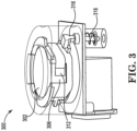
- the print substance apparatus 300 includes a locking mechanism 316 that can interact with a locking portion 314 of the mating interface 302. As described herein, the locking mechanism 316 can prevent the mating interface 302 from rotating when the locking mechanism 316 is in a locked position. As described herein, the locking mechanism 316 can be unlocked when the print particle dispense nozzle is authenticated. For example, the locking mechanism 316 can lock the mating interface 302 in a closed position until the print particle dispense nozzle is authenticated through the electrical contact 306 and/or the flexible cable 312.
- the print substance apparatus 300 includes a mating interface 302 coupled to a dispense interface 308 to interact with a print particle dispense nozzle.
- the print substance apparatus 300 includes an electrical interface 306 positioned at an interior portion of the mating interface 302 to interact with a corresponding electrical interface of the print particle dispense nozzle when the print particle dispense nozzle is positioned within the mating interface 302.
- the print substance apparatus 300 includes a locking mechanism 316 coupled to the dispense interface 308 to interact with a locking tab (e.g., locking portion 214 as illustrated in Figure 2 , etc.) of the mating interface 302.
- the print substance apparatus 300 includes an authentication mechanism or circuit assembly coupled to the locking mechanism 316 to receive a first signal from the print particle dispense nozzle to authenticate the print particle dispense nozzle and unlock the locking mechanism 316 to allow the mating interface 302 to rotate from a first position to a second position.
- the authentication mechanism receives a second signal from the print particle dispense nozzle to confirm the print particle dispense nozzle is empty and unlock the locking mechanism 316 to allow the mating interface 302 to rotate from the second position to the first position.
- the authentication mechanism can lock the locking mechanism 316 when the mating interface 302 is at the second position to prevent the print particle dispense nozzle from being removed from the mating interface 302 at the second position.
- the print substance apparatus 300 can be utilized to authenticate print particle dispense nozzles. As described herein, authenticating the print particle dispense nozzles can prevent unwanted print particle dispense nozzles from dispensing print material particles into the print material particle reservoir of the imaging device.
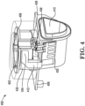
- Figure 4 illustrates a view of an example of a print substance apparatus 400 consistent with the disclosure.
- the print substance apparatus 400 can include the same or similar components as the print substance apparatus 100 as illustrated in Figure 1 , the print substance apparatus 200 as referenced in Figure 2 , and/or the print substance apparatus 300 as referenced in Figure 3 .
- the print substance apparatus 400 includes a rotatable mating interface 402 that includes an aperture to receive a print particle dispense nozzle.
- the print substance apparatus 400 can include a first circuit assembly 406 that includes an electrical contact positioned at an interior location of the aperture to interact with the print particle dispense nozzle when the print particle dispense nozzle is positioned within the aperture of the rotatable mating interface 402.
- the flexible cable 412 can wrap around a portion of the exterior portion of the rotatable mating interface 402 when the rotatable mating interface 402 is rotated from a first position to a second position.
- the flexible cable 412 is a ribbon cable that includes a plurality of individual communication channels.
- a ribbon cable includes a multi-wire planar cable with a plurality of conductive wires running parallel to each other in a flat plane.
- the flexible cable 412 can communicatively couple the first circuit assembly 406 and the second circuit assembly 430 during a rotation of the rotatable mating interface. In this way, the print particle dispense nozzle can be authenticated during the rotation to prevent an initial authorization followed by an unauthorized print particle dispense nozzle depositing the print material particles into the print substance apparatus 400.
- the print substance apparatus 400 can include a contact 436 coupled to the second circuit assembly 430 that interacts with the mating interface 402 at a particular position.
- the mating interface 402 can include a tab 438 that can interact with the contact 436.
- the second circuit assembly 430 can determine a position of the mating interface 402 when the tab 436 interacts with the contact 436.
- the second circuit assembly 430 can determine that the mating interface 402 is in an open position when the tab 436 interacts with the contact 436.
- a locking mechanism can be altered to a locked position when the tab 436 interacts with the contact 436 to lock the mating interface 402 in a locked position.
- the contact 436 can be a spring contact that indicates a proximity of a tab 436 coupled to the mating interface 402.
- a spring contact can include a spring loaded conductive contact that can be depressed to generate a signal.
- the print substance apparatus 400 can include a bracket 432 coupled to the dispense interface 408.
- the bracket 432 can guide the flexible cable 412 from the second circuit assembly 430 to an exterior portion of the mating interface 402.
- the flexible cable 412 can include an excess portion 434 that allows the flexible cable 412 to wrap around the exterior portion of the mating interface 402 when the mating interface 402 is rotated from a first position to a second position. In this way, the flexible cable 412 can provide continuous communication between the first circuit assembly 406 and the second circuit assembly 430 during rotation of the mating interface 402. Providing continuous communication between the first circuit assembly 406 and the second circuit assembly 430 can prevent unauthorized print particle dispense nozzles from depositing print particles into the print substance apparatus 400.
- the print substance apparatus 400 can include a dispense interface 408 that includes a port 410 that can be coupled to a print material particle reservoir of the imaging device.
- the rotatable mating interface 402 can include a port that can provide the print material particles to the port 410 of the dispense interface 408 in an open position and prevent the print material particles from entering the port 410 in a closed position.
- the rotatable mating interface 402 can rotate to alter between the closed position and the open position.
- the rotatable mating interface 402 can be locked in a first position (e.g., closed position) until the print particle dispense nozzle is authenticated. When the print particle dispense nozzle is authenticated, the rotatable mating interface 402 is rotated from the first position to a second position (e.g., open position).
- the print substance apparatus 400 can include a dispense interface 408 coupled to the print particle supply or print particle reservoir.
- the print substance apparatus 400 can also include a mating interface 402 coupled to the dispense interface 408 to interact with a print particle dispense nozzle.
- the mating interface 402 is rotatable from a first position to a second position.
- the print substance apparatus 400 includes a locking mechanism coupled to the dispense interface 408 to control the rotation of the mating interface 402.
- an authentication mechanism e.g., second circuit assembly 430
- the second circuit assembly 430 can be utilized to receive a first signal from the print particle dispense nozzle when the mating interface 402 is in the first position.
- the second circuit assembly 430 can authenticate the print particle dispense nozzle based on the first signal.
- the second circuit assembly can then instruct the locking mechanism to allow the mating interface 402 to rotate from the first position to the second position when the print particle dispense nozzle is authenticated.
- the first signal can be information or authentication information for the print particle dispense nozzle.
- the first signal can include a manufacturer of the print particle dispense nozzle and a type of print particle within the print particle dispense nozzle.
- the print particle dispense nozzle can be authenticated when the type of print particles within the print particle dispense nozzle match print particles to be dispensed by the print particle apparatus 400.
- the second circuit assembly can also receive a second signal from the print particle dispense nozzle when the mating interface 402 is in the second position and instruct the locking mechanism to allow the mating interface 402 to rotate from the second position to the first position based on the second signal.
- the second signal can include an indication that the print particle dispense nozzle includes a particular quantity of a print particle.
- the second signal can be a signal that the print particle dispense nozzle is empty or that the print particle dispense nozzle has deposited a particular quantity of print particles to the print particle apparatus 400.
- the print substance apparatus 400 can be utilized to authenticate print particle dispense nozzles. As described herein, authenticating the print particle dispense nozzles can prevent unwanted print particle dispense nozzles from dispensing print material particles into the print material particle reservoir of the imaging device.
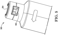
- Figure 5 illustrates a view of an example of a print particle dispense nozzle 560 consistent with the disclosure.
- the print particle dispense nozzle 560 can be a syringe that includes print material particles as described herein.
- the print particle dispense nozzle 560 can include an output nozzle 564 that can be inserted into a mating interface as described herein.
- the output nozzle 564 can be utilized to dispense the print material particles when the mating interface of a print substance apparatus is rotated from a closed position to an open position.
- the print particle dispense nozzle 560 can include a circuit assembly 562 that includes contacts that can interact with contacts of a print substance apparatus.
- the circuit assembly 562 can be utilized to transmit signals to a circuit assembly coupled to a mating interface.
- contacts of the circuit assembly 562 can interact with contacts of the mating interface to provide information relating to the print particle dispense nozzle 560.
- the information transmitted to the mating interface can be authentication information.
- the authentication information can include information to authenticate the print particle dispense nozzle 560.
- the authentication information can include a type of print particles within the print particle dispense nozzle 560.
- the authentication information can include a manufacturer of the print particle dispense nozzle 560.
- Figure 6 illustrates a view of an example of a print substance apparatus 600-1, 600-2 consistent with the disclosure.
- the print substance apparatus 600-1, 600-2 can include the same or similar components as the print substance apparatus 100 as illustrated in Figure 1 , the print substance apparatus 200 as referenced in Figure 2 , the print substance apparatus 300 as referenced in Figure 3 , and/or the print substance apparatus 400 as referenced in Figure 4 .
- the print substance apparatus 600-1 can illustrate the when the apparatus is in a closed position and the print substance apparatus 600-2 can illustrate when the apparatus is in an open position.
- a print substance apparatus 600-1, 600-2 includes a rotatable mating interface 602 that can be rotated between a closed position as illustrated by apparatus 600-1 to an open position as illustrated by apparatus 600-2.
- the print substance apparatus 600-1, 600-2 can include a cover tab 672 that can cover an aperture 674 in the closed position as illustrated by the print substance apparatus 600-1.
- a print particle dispense nozzle can be authenticated and the cover tab 672 can be rotated by the mating interface 602 from a position that covers the aperture 674 to a position that does not cover the aperture 674.
- the rotatable mating interface 602 can be rotated from the open position to the closed position.
- the print substance apparatus 600-1, 600-2 can be utilized to authenticate print particle dispense nozzles. As described herein, authenticating the print particle dispense nozzles can prevent unwanted print particle dispense nozzles from dispensing print material particles into the print material particle reservoir of the imaging device. In some examples, an authentication mechanism or circuit assembly can authenticate the print particle dispense nozzle by comparing the print particles of the print particle dispense nozzle to a print particle type to be received by the dispense interface.
Landscapes
- Physics & Mathematics (AREA)
- General Physics & Mathematics (AREA)
- Ink Jet (AREA)
- Ink Jet Recording Methods And Recording Media Thereof (AREA)
- Accessory Devices And Overall Control Thereof (AREA)
Claims (14)
- Einrichtung (100), die umfasst:eine Passschnittstelle (102), die mit einer Abgabeschnittstelle (108), die dazu konfiguriert ist, mit einer Druckpartikelabgabedüse (560) zusammenzuwirken, gekoppelt ist;einen Sperrmechanismus (216), der mit der Abgabeschnittstelle (108) gekoppelt ist, der dazu konfiguriert ist, zu verhindern, dass die Druckpartikelabgabedüse (560) einen Druckpartikel auf der Abgabeschnittstelle (108) abscheidet; undeinen Authentifizierungsmechanismus, der mit dem Sperrmechanismus (216) gekoppelt ist, der dazu konfiguriert ist:Authentifizieren der Druckpartikelabgabedüse (560); undEntsperren des Sperrmechanismus (216), wenn die Druckpartikelabgabedüse (560) authentifiziert ist, um der Druckpartikelabgabedüse (560) zu ermöglichen, den Druckpartikel auf der Abgabeschnittstelle (108) abzuscheiden,wobei die Passschnittstelle (102) von einer ersten Position in eine zweite Position drehbar ist, wenn der Sperrmechanismus (216) durch den Authentifizierungsmechanismus entsperrt ist.
- Einrichtung (100) nach Anspruch 1, die eine elektrische Schnittstelle (306), die mit der Passschnittstelle (102) gekoppelt und dazu konfiguriert ist, ein Signal von der Druckpartikelabgabedüse (560) zu empfangen, umfasst.
- Einrichtung (100) nach Anspruch 2, wobei das Signal durch den Authentifizierungsmechanismus empfangen wird, um die Druckpartikelabgabedüse (560) zu authentifizieren.
- Einrichtung (100) nach Anspruch 1, wobei eine Öffnung zwischen der Passschnittstelle (102) und der Abgabeschnittstelle (108) geschlossen ist, wenn sich die Passschnittstelle (102) in der ersten Position befindet, und geöffnet ist, wenn sich die Passschnittstelle (102) in der zweiten Position befindet.
- Einrichtung (100) nach Anspruch 1, wobei der Authentifizierungsmechanismus die Druckpartikelabgabedüse (560) durch ein Vergleichen des Druckpartikels der Druckpartikelabgabedüse (560) mit einem Druckpartikeltyp, der durch die Abgabeschnittstelle (108) zu empfangen ist, authentifiziert.
- Einrichtung (100) nach Anspruch 5, wobei der Druckpartikeltyp, der durch die Abgabeschnittstelle (108) zu empfangen ist, ein Typ von Druckpartikeln ist, der in einer Druckpartikelzufuhr, die mit der Abgabeschnittstelle (108) gekoppelt ist, gespeichert ist.
- Einrichtung (100) nach Anspruch 1, die ferner umfasst:eine Abgabeschnittstelle (108), die mit der Druckpartikelzufuhr gekoppelt ist,wobei der Sperrmechanismus (216) dazu konfiguriert ist, die Drehung der Passschnittstelle (102) zu steuern, undwobei der Authentifizierungsmechanismus dazu konfiguriert ist:Empfangen eines ersten Signals von der Druckpartikelabgabedüse (560), wenn sich die Passschnittstelle (102) in der ersten Position befindet;Authentifizieren der Druckpartikelabgabedüse (560) auf der Basis von dem ersten Signal; Anweisen des Sperrmechanismus (216), der Passschnittstelle (102) zu ermöglichen, sich von der ersten Position in die zweite Position zu drehen, wenn die Druckpartikelabgabedüse (560) authentifiziert ist;Empfangen eines zweiten Signals von der Druckpartikelabgabedüse (560), wenn sich die Passschnittstelle (102) in der zweiten Position befindet; undAnweisen des Sperrmechanismus (216), der Passschnittstelle (102) zu ermöglichen, von der zweiten Position in die erste Position auf der Basis von dem zweiten Signal zu drehen.
- Einrichtung (100) nach Anspruch 7, wobei das erste Signal einen Hersteller der Druckpartikelabgabedüse (560) und einen Typ von Druckpartikeln innerhalb der Druckpartikelabgabedüse (560) einschließt.
- Einrichtung (100) nach Anspruch 7, wobei das zweite Signal eine Anzeige einschließt, dass die Druckpartikelabgabedüse (560) eine bestimmte Menge eines Druckpartikels einschließt.
- System (100, 200), das umfasst:eine Passschnittstelle (102), die mit einer Abgabeschnittstelle (108), die dazu konfiguriert ist, mit einer Druckpartikelabgabedüse (560) zusammenzuwirken, gekoppelt ist;eine elektrische Schnittstelle (306), die an einem inneren Abschnitt der Passschnittstelle (102) positioniert und dazu konfiguriert ist, mit einer entsprechenden elektrischen Schnittstelle (306) der Druckpartikelabgabedüse (560) zusammenzuwirken, wenn die Druckpartikelabgabedüse (560) innerhalb der Passschnittstelle (102) positioniert ist;einen Sperrmechanismus (216), der mit der Abgabeschnittstelle (108) gekoppelt und dazu konfiguriert ist, mit einer Sperrlasche der Passschnittstelle (102) zusammenzuwirken; undeinen Authentifizierungsmechanismus, der mit dem Sperrmechanismus (216) gekoppelt und dazu konfiguriert ist: Empfangen eines ersten Signals von der Druckpartikelabgabedüse (560), um die Druckpartikelabgabedüse (560) zu authentifizieren;Entsperren des Sperrmechanismus (216), um der Passschnittstelle (102) zu ermöglichen, sich von einer ersten Position in eine zweite Position zu drehen;Empfangen eines zweiten Signals von der Druckpartikelabgabedüse (560), um zu bestätigen, dass die Druckpartikelabgabedüse (560) leer ist; undEntsperren des Sperrmechanismus (216), um der Passschnittstelle (102) zu ermöglichen, sich von der zweiten Position in die erste Position zu drehen.
- System nach Anspruch 10, wobei der Authentifizierungsmechanismus dazu konfiguriert ist, den Sperrmechanismus (216) zu sperren, wenn sich die Passschnittstelle (102) in der zweiten Position befindet.
- System nach Anspruch 10, wobei die Sperrlasche auf einem äußeren Abschnitt der Passschnittstelle (102) positioniert ist.
- System nach Anspruch 10, wobei die Passschnittstelle (102) eine erste Öffnung einschließt und die Abgabeschnittstelle (108) eine zweite Öffnung (110) einschließt.
- System nach Anspruch 13, wobei die erste Öffnung und die zweite Öffnung (110) ausgerichtet sind, wenn sich die Passschnittstelle (102) in der zweiten Position befindet, um einem Druckpartikel zu ermöglichen, durch die erste Öffnung und die zweite Öffnung (110) zu passieren.
Applications Claiming Priority (1)
| Application Number | Priority Date | Filing Date | Title |
|---|---|---|---|
| PCT/US2018/048796 WO2020046328A1 (en) | 2018-08-30 | 2018-08-30 | Authentication mechanisms |
Publications (2)
| Publication Number | Publication Date |
|---|---|
| EP3787901A1 EP3787901A1 (de) | 2021-03-10 |
| EP3787901B1 true EP3787901B1 (de) | 2025-03-26 |
Family
ID=63529035
Family Applications (1)
| Application Number | Title | Priority Date | Filing Date |
|---|---|---|---|
| EP18766571.6A Active EP3787901B1 (de) | 2018-08-30 | 2018-08-30 | Authentifizierungsmechanismen |
Country Status (6)
| Country | Link |
|---|---|
| US (1) | US11364725B2 (de) |
| EP (1) | EP3787901B1 (de) |
| CN (1) | CN112399920B (de) |
| MX (1) | MX2020013449A (de) |
| RU (1) | RU2768201C1 (de) |
| WO (1) | WO2020046328A1 (de) |
Families Citing this family (1)
| Publication number | Priority date | Publication date | Assignee | Title |
|---|---|---|---|---|
| MX2020014148A (es) * | 2018-08-30 | 2021-03-25 | Hewlett Packard Development Co | Dispositivos de recarga de impresion. |
Family Cites Families (27)
| Publication number | Priority date | Publication date | Assignee | Title |
|---|---|---|---|---|
| US2641743A (en) | 1949-07-26 | 1953-06-09 | Lionel Corp | Transformer |
| DE3836365A1 (de) * | 1988-10-26 | 1990-05-10 | Schering Ag | Befuelleinrichtung |
| JP3167789B2 (ja) | 1992-06-03 | 2001-05-21 | キヤノン株式会社 | インクジェット記録装置及びインク残量低下検知方法 |
| AUPP702198A0 (en) | 1998-11-09 | 1998-12-03 | Silverbrook Research Pty Ltd | Image creation method and apparatus (ART79) |
| US6658219B1 (en) | 1999-09-30 | 2003-12-02 | Fuji Photo Film Co., Ltd. | Method, device, system and recording medium for detecting improper cartridge, and cartridge |
| US6350014B1 (en) * | 2000-03-01 | 2002-02-26 | Eastman Kodak Company | Apparatus for using nanoparticles for printing images |
| MXPA03010697A (es) * | 2001-05-21 | 2005-03-07 | Colder Prod Co | Aparato conector y metodo para conectar el mismo para controlar la dosificacion de fluidos. |
| US7234787B2 (en) * | 2004-01-08 | 2007-06-26 | Eastman Kodak Company | Liquid level detection method and apparatus |
| US7344232B2 (en) | 2004-01-21 | 2008-03-18 | Silverbrook Research Pty Ltd | Inkjet printer cartridge refill dispenser with security lock for spent refill |
| JP4750403B2 (ja) | 2004-11-12 | 2011-08-17 | キヤノン株式会社 | 画像形成装置 |
| US7621426B2 (en) * | 2004-12-15 | 2009-11-24 | Joseph Kanfer | Electronically keyed dispensing systems and related methods utilizing near field frequency response |
| US7350895B2 (en) * | 2005-04-20 | 2008-04-01 | John Tiedge | Printing container fill indicator |
| US7874660B2 (en) * | 2007-10-10 | 2011-01-25 | Hewlett-Packard Development Company, L.P. | Closure and connector for a supply container |
| JP5350998B2 (ja) | 2008-12-24 | 2013-11-27 | 京セラドキュメントソリューションズ株式会社 | トナーカートリッジ及び該トナーカートリッジが組み込まれた画像形成装置 |
| JP5602386B2 (ja) | 2009-04-23 | 2014-10-08 | キヤノン株式会社 | トナー供給装置 |
| US8588659B2 (en) | 2011-12-30 | 2013-11-19 | Lexmark International, Inc. | Toner cartridge having a shutter lock mechanism |
| US8985165B2 (en) * | 2012-03-23 | 2015-03-24 | Xerox Corporation | Apparatus, method and system for carrying and dispensing an ink useful in printing |
| JP2013201555A (ja) * | 2012-03-23 | 2013-10-03 | Canon Inc | 通信装置、アドレス設定方法およびプログラム |
| GB2503259B (en) * | 2012-06-20 | 2014-10-01 | Bernard Edgar Anning | Apparatus for inventory control |
| WO2014145074A1 (en) | 2013-03-15 | 2014-09-18 | Makefield Llc | Functional desiccants |
| US9098055B2 (en) | 2013-12-17 | 2015-08-04 | Lexmark International, Inc. | Methods and systems for locking a replaceable unit in an image forming device |
| US9475298B2 (en) * | 2015-01-19 | 2016-10-25 | Brother Kogyo Kabushiki Kaisha | Liquid consuming apparatus |
| JP2017193105A (ja) * | 2016-04-20 | 2017-10-26 | キヤノン株式会社 | 液体収納容器ユニット |
| JP6661462B2 (ja) * | 2016-05-16 | 2020-03-11 | キヤノン株式会社 | 液体吐出装置および液体補給容器 |
| US10399347B2 (en) * | 2016-06-29 | 2019-09-03 | Canon Kabushiki Kaisha | Liquid supplying mechanism, and liquid ejection apparatus |
| JP6658401B2 (ja) * | 2016-08-26 | 2020-03-04 | 京セラドキュメントソリューションズ株式会社 | トナー容器及び画像形成装置 |
| ES2890935T3 (es) * | 2017-03-14 | 2022-01-25 | Illinois Tool Works | Conjunto de conexión rápida para conexiones eléctricas y de fluidos |
-
2018
- 2018-08-30 EP EP18766571.6A patent/EP3787901B1/de active Active
- 2018-08-30 RU RU2021100977A patent/RU2768201C1/ru active
- 2018-08-30 US US17/050,146 patent/US11364725B2/en active Active
- 2018-08-30 MX MX2020013449A patent/MX2020013449A/es unknown
- 2018-08-30 WO PCT/US2018/048796 patent/WO2020046328A1/en not_active Ceased
- 2018-08-30 CN CN201880095597.9A patent/CN112399920B/zh active Active
Also Published As
| Publication number | Publication date |
|---|---|
| BR112021003555A2 (pt) | 2021-05-18 |
| US20210094304A1 (en) | 2021-04-01 |
| MX2020013449A (es) | 2021-02-26 |
| WO2020046328A1 (en) | 2020-03-05 |
| CN112399920B (zh) | 2023-01-10 |
| RU2768201C1 (ru) | 2022-03-23 |
| EP3787901A1 (de) | 2021-03-10 |
| CN112399920A (zh) | 2021-02-23 |
| US11364725B2 (en) | 2022-06-21 |
Similar Documents
| Publication | Publication Date | Title |
|---|---|---|
| EP3787901B1 (de) | Authentifizierungsmechanismen | |
| CN108602277B (zh) | 用于增材制造的数据单元 | |
| US11269267B2 (en) | Contact pads on an output assembly of a print particle replenishment device including an interior disk and a cover disk | |
| TW201345737A (zh) | 匣體及印刷材料供給系統 | |
| EP3137304B1 (de) | An einen flussstimulator in einer kassette gekoppelter authentizitätsinformationsträger | |
| US20210234323A1 (en) | Flexible cables | |
| CN111093954A (zh) | 用于耦接到构建材料容纳器的阀机构 | |
| US11454921B2 (en) | Contacts for a print particle input recess | |
| BR112021003555B1 (pt) | Aparelho, sistema e suprimento de partículas de impressão compreendendo mecanismos de autenticação | |
| CN111107979A (zh) | 用于三维打印机的构建材料容纳器 | |
| EP3785082B1 (de) | Authentifizierung von drucksubstanzmesslehren | |
| US11914311B2 (en) | Print particle supply valves | |
| EP3752338B1 (de) | Verwaltungssystem und verfahren für ein generatives herstellungsverfahren | |
| BR112021009289B1 (pt) | Aparelhos e sistema de autenticação de medidor de substância de impressão | |
| WO2017194137A1 (en) | Additive manufacturing authentication | |
| CN112423990A (zh) | 无人参与的储存器再填充 | |
| IL260746A (en) | Package collection management system | |
| IT9021960A1 (it) | Dispositivo computerizzato per il pagamento dei rifornimenti per autoveicoli in generale |
Legal Events
| Date | Code | Title | Description |
|---|---|---|---|
| STAA | Information on the status of an ep patent application or granted ep patent |
Free format text: STATUS: UNKNOWN |
|
| STAA | Information on the status of an ep patent application or granted ep patent |
Free format text: STATUS: THE INTERNATIONAL PUBLICATION HAS BEEN MADE |
|
| PUAI | Public reference made under article 153(3) epc to a published international application that has entered the european phase |
Free format text: ORIGINAL CODE: 0009012 |
|
| STAA | Information on the status of an ep patent application or granted ep patent |
Free format text: STATUS: REQUEST FOR EXAMINATION WAS MADE |
|
| 17P | Request for examination filed |
Effective date: 20201014 |
|
| AK | Designated contracting states |
Kind code of ref document: A1 Designated state(s): AL AT BE BG CH CY CZ DE DK EE ES FI FR GB GR HR HU IE IS IT LI LT LU LV MC MK MT NL NO PL PT RO RS SE SI SK SM TR |
|
| AX | Request for extension of the european patent |
Extension state: BA ME |
|
| DAV | Request for validation of the european patent (deleted) | ||
| DAX | Request for extension of the european patent (deleted) | ||
| STAA | Information on the status of an ep patent application or granted ep patent |
Free format text: STATUS: EXAMINATION IS IN PROGRESS |
|
| 17Q | First examination report despatched |
Effective date: 20221013 |
|
| GRAP | Despatch of communication of intention to grant a patent |
Free format text: ORIGINAL CODE: EPIDOSNIGR1 |
|
| STAA | Information on the status of an ep patent application or granted ep patent |
Free format text: STATUS: GRANT OF PATENT IS INTENDED |
|
| INTG | Intention to grant announced |
Effective date: 20241119 |
|
| GRAS | Grant fee paid |
Free format text: ORIGINAL CODE: EPIDOSNIGR3 |
|
| GRAA | (expected) grant |
Free format text: ORIGINAL CODE: 0009210 |
|
| STAA | Information on the status of an ep patent application or granted ep patent |
Free format text: STATUS: THE PATENT HAS BEEN GRANTED |
|
| RIN1 | Information on inventor provided before grant (corrected) |
Inventor name: HICKMAN, ZACKARY THOMAS Inventor name: NADEAU, BENNETT ALEXANDER Inventor name: TRAN, AN Inventor name: STOREY, MATTHEW JAMES Inventor name: HONG, JINHWA Inventor name: LEE, SEUNGSUP Inventor name: CHOI, WOONGYONG Inventor name: LEE, MINCHUL Inventor name: MOON, JIWON |
|
| AK | Designated contracting states |
Kind code of ref document: B1 Designated state(s): AL AT BE BG CH CY CZ DE DK EE ES FI FR GB GR HR HU IE IS IT LI LT LU LV MC MK MT NL NO PL PT RO RS SE SI SK SM TR |
|
| REG | Reference to a national code |
Ref country code: GB Ref legal event code: FG4D |
|
| REG | Reference to a national code |
Ref country code: CH Ref legal event code: EP |
|
| REG | Reference to a national code |
Ref country code: DE Ref legal event code: R096 Ref document number: 602018080476 Country of ref document: DE |
|
| REG | Reference to a national code |
Ref country code: IE Ref legal event code: FG4D Ref country code: NL Ref legal event code: FP |
|
| PG25 | Lapsed in a contracting state [announced via postgrant information from national office to epo] |
Ref country code: RS Free format text: LAPSE BECAUSE OF FAILURE TO SUBMIT A TRANSLATION OF THE DESCRIPTION OR TO PAY THE FEE WITHIN THE PRESCRIBED TIME-LIMIT Effective date: 20250626 |
|
| PG25 | Lapsed in a contracting state [announced via postgrant information from national office to epo] |
Ref country code: FI Free format text: LAPSE BECAUSE OF FAILURE TO SUBMIT A TRANSLATION OF THE DESCRIPTION OR TO PAY THE FEE WITHIN THE PRESCRIBED TIME-LIMIT Effective date: 20250326 |
|
| REG | Reference to a national code |
Ref country code: LT Ref legal event code: MG9D |
|
| PG25 | Lapsed in a contracting state [announced via postgrant information from national office to epo] |
Ref country code: NO Free format text: LAPSE BECAUSE OF FAILURE TO SUBMIT A TRANSLATION OF THE DESCRIPTION OR TO PAY THE FEE WITHIN THE PRESCRIBED TIME-LIMIT Effective date: 20250626 |
|
| PG25 | Lapsed in a contracting state [announced via postgrant information from national office to epo] |
Ref country code: HR Free format text: LAPSE BECAUSE OF FAILURE TO SUBMIT A TRANSLATION OF THE DESCRIPTION OR TO PAY THE FEE WITHIN THE PRESCRIBED TIME-LIMIT Effective date: 20250326 |
|
| PG25 | Lapsed in a contracting state [announced via postgrant information from national office to epo] |
Ref country code: LV Free format text: LAPSE BECAUSE OF FAILURE TO SUBMIT A TRANSLATION OF THE DESCRIPTION OR TO PAY THE FEE WITHIN THE PRESCRIBED TIME-LIMIT Effective date: 20250326 |
|
| PG25 | Lapsed in a contracting state [announced via postgrant information from national office to epo] |
Ref country code: GR Free format text: LAPSE BECAUSE OF FAILURE TO SUBMIT A TRANSLATION OF THE DESCRIPTION OR TO PAY THE FEE WITHIN THE PRESCRIBED TIME-LIMIT Effective date: 20250627 Ref country code: BG Free format text: LAPSE BECAUSE OF FAILURE TO SUBMIT A TRANSLATION OF THE DESCRIPTION OR TO PAY THE FEE WITHIN THE PRESCRIBED TIME-LIMIT Effective date: 20250326 |
|
| PGFP | Annual fee paid to national office [announced via postgrant information from national office to epo] |
Ref country code: NL Payment date: 20250723 Year of fee payment: 8 |
|
| PG25 | Lapsed in a contracting state [announced via postgrant information from national office to epo] |
Ref country code: SE Free format text: LAPSE BECAUSE OF FAILURE TO SUBMIT A TRANSLATION OF THE DESCRIPTION OR TO PAY THE FEE WITHIN THE PRESCRIBED TIME-LIMIT Effective date: 20250326 |
|
| REG | Reference to a national code |
Ref country code: AT Ref legal event code: MK05 Ref document number: 1778691 Country of ref document: AT Kind code of ref document: T Effective date: 20250326 |
|
| PG25 | Lapsed in a contracting state [announced via postgrant information from national office to epo] |
Ref country code: SM Free format text: LAPSE BECAUSE OF FAILURE TO SUBMIT A TRANSLATION OF THE DESCRIPTION OR TO PAY THE FEE WITHIN THE PRESCRIBED TIME-LIMIT Effective date: 20250326 |
|
| PG25 | Lapsed in a contracting state [announced via postgrant information from national office to epo] |
Ref country code: PT Free format text: LAPSE BECAUSE OF FAILURE TO SUBMIT A TRANSLATION OF THE DESCRIPTION OR TO PAY THE FEE WITHIN THE PRESCRIBED TIME-LIMIT Effective date: 20250728 Ref country code: ES Free format text: LAPSE BECAUSE OF FAILURE TO SUBMIT A TRANSLATION OF THE DESCRIPTION OR TO PAY THE FEE WITHIN THE PRESCRIBED TIME-LIMIT Effective date: 20250326 |
|
| PGFP | Annual fee paid to national office [announced via postgrant information from national office to epo] |
Ref country code: DE Payment date: 20250724 Year of fee payment: 8 |
|
| PG25 | Lapsed in a contracting state [announced via postgrant information from national office to epo] |
Ref country code: PL Free format text: LAPSE BECAUSE OF FAILURE TO SUBMIT A TRANSLATION OF THE DESCRIPTION OR TO PAY THE FEE WITHIN THE PRESCRIBED TIME-LIMIT Effective date: 20250326 Ref country code: IT Free format text: LAPSE BECAUSE OF FAILURE TO SUBMIT A TRANSLATION OF THE DESCRIPTION OR TO PAY THE FEE WITHIN THE PRESCRIBED TIME-LIMIT Effective date: 20250326 |
|
| PGFP | Annual fee paid to national office [announced via postgrant information from national office to epo] |
Ref country code: GB Payment date: 20250725 Year of fee payment: 8 |
|
| PG25 | Lapsed in a contracting state [announced via postgrant information from national office to epo] |
Ref country code: AT Free format text: LAPSE BECAUSE OF FAILURE TO SUBMIT A TRANSLATION OF THE DESCRIPTION OR TO PAY THE FEE WITHIN THE PRESCRIBED TIME-LIMIT Effective date: 20250326 |
|
| PGFP | Annual fee paid to national office [announced via postgrant information from national office to epo] |
Ref country code: FR Payment date: 20250723 Year of fee payment: 8 |
|
| PG25 | Lapsed in a contracting state [announced via postgrant information from national office to epo] |
Ref country code: EE Free format text: LAPSE BECAUSE OF FAILURE TO SUBMIT A TRANSLATION OF THE DESCRIPTION OR TO PAY THE FEE WITHIN THE PRESCRIBED TIME-LIMIT Effective date: 20250326 |
|
| PG25 | Lapsed in a contracting state [announced via postgrant information from national office to epo] |
Ref country code: RO Free format text: LAPSE BECAUSE OF FAILURE TO SUBMIT A TRANSLATION OF THE DESCRIPTION OR TO PAY THE FEE WITHIN THE PRESCRIBED TIME-LIMIT Effective date: 20250326 |
|
| PG25 | Lapsed in a contracting state [announced via postgrant information from national office to epo] |
Ref country code: SK Free format text: LAPSE BECAUSE OF FAILURE TO SUBMIT A TRANSLATION OF THE DESCRIPTION OR TO PAY THE FEE WITHIN THE PRESCRIBED TIME-LIMIT Effective date: 20250326 |
|
| PG25 | Lapsed in a contracting state [announced via postgrant information from national office to epo] |
Ref country code: IS Free format text: LAPSE BECAUSE OF FAILURE TO SUBMIT A TRANSLATION OF THE DESCRIPTION OR TO PAY THE FEE WITHIN THE PRESCRIBED TIME-LIMIT Effective date: 20250726 |
|
| REG | Reference to a national code |
Ref country code: DE Ref legal event code: R097 Ref document number: 602018080476 Country of ref document: DE |
|
| PG25 | Lapsed in a contracting state [announced via postgrant information from national office to epo] |
Ref country code: DK Free format text: LAPSE BECAUSE OF FAILURE TO SUBMIT A TRANSLATION OF THE DESCRIPTION OR TO PAY THE FEE WITHIN THE PRESCRIBED TIME-LIMIT Effective date: 20250326 |
|
| PG25 | Lapsed in a contracting state [announced via postgrant information from national office to epo] |
Ref country code: CZ Free format text: LAPSE BECAUSE OF FAILURE TO SUBMIT A TRANSLATION OF THE DESCRIPTION OR TO PAY THE FEE WITHIN THE PRESCRIBED TIME-LIMIT Effective date: 20250326 |
|
| PLBE | No opposition filed within time limit |
Free format text: ORIGINAL CODE: 0009261 |
|
| STAA | Information on the status of an ep patent application or granted ep patent |
Free format text: STATUS: NO OPPOSITION FILED WITHIN TIME LIMIT |
|
| REG | Reference to a national code |
Ref country code: CH Ref legal event code: L10 Free format text: ST27 STATUS EVENT CODE: U-0-0-L10-L00 (AS PROVIDED BY THE NATIONAL OFFICE) Effective date: 20260211 |
|
| 26N | No opposition filed |
Effective date: 20260105 |
|
| REG | Reference to a national code |
Ref country code: CH Ref legal event code: H13 Free format text: ST27 STATUS EVENT CODE: U-0-0-H10-H13 (AS PROVIDED BY THE NATIONAL OFFICE) Effective date: 20260324 |