EP3787141A1 - Method for determining a power component, operating method, control unit, energy storage assembly and power network - Google Patents
Method for determining a power component, operating method, control unit, energy storage assembly and power network Download PDFInfo
- Publication number
- EP3787141A1 EP3787141A1 EP20181618.8A EP20181618A EP3787141A1 EP 3787141 A1 EP3787141 A1 EP 3787141A1 EP 20181618 A EP20181618 A EP 20181618A EP 3787141 A1 EP3787141 A1 EP 3787141A1
- Authority
- EP
- European Patent Office
- Prior art keywords
- soc
- power
- electrical
- prog
- dch
- Prior art date
- Legal status (The legal status is an assumption and is not a legal conclusion. Google has not performed a legal analysis and makes no representation as to the accuracy of the status listed.)
- Pending
Links
Images


Classifications
-
- B—PERFORMING OPERATIONS; TRANSPORTING
- B60—VEHICLES IN GENERAL
- B60L—PROPULSION OF ELECTRICALLY-PROPELLED VEHICLES; SUPPLYING ELECTRIC POWER FOR AUXILIARY EQUIPMENT OF ELECTRICALLY-PROPELLED VEHICLES; ELECTRODYNAMIC BRAKE SYSTEMS FOR VEHICLES IN GENERAL; MAGNETIC SUSPENSION OR LEVITATION FOR VEHICLES; MONITORING OPERATING VARIABLES OF ELECTRICALLY-PROPELLED VEHICLES; ELECTRIC SAFETY DEVICES FOR ELECTRICALLY-PROPELLED VEHICLES
- B60L53/00—Methods of charging batteries, specially adapted for electric vehicles; Charging stations or on-board charging equipment therefor; Exchange of energy storage elements in electric vehicles
- B60L53/50—Charging stations characterised by energy-storage or power-generation means
- B60L53/53—Batteries
-
- G—PHYSICS
- G01—MEASURING; TESTING
- G01R—MEASURING ELECTRIC VARIABLES; MEASURING MAGNETIC VARIABLES
- G01R31/00—Arrangements for testing electric properties; Arrangements for locating electric faults; Arrangements for electrical testing characterised by what is being tested not provided for elsewhere
- G01R31/36—Arrangements for testing, measuring or monitoring the electrical condition of accumulators or electric batteries, e.g. capacity or state of charge [SoC]
- G01R31/385—Arrangements for measuring battery or accumulator variables
- G01R31/387—Determining ampere-hour charge capacity or SoC
-
- G—PHYSICS
- G01—MEASURING; TESTING
- G01R—MEASURING ELECTRIC VARIABLES; MEASURING MAGNETIC VARIABLES
- G01R31/00—Arrangements for testing electric properties; Arrangements for locating electric faults; Arrangements for electrical testing characterised by what is being tested not provided for elsewhere
- G01R31/36—Arrangements for testing, measuring or monitoring the electrical condition of accumulators or electric batteries, e.g. capacity or state of charge [SoC]
- G01R31/392—Determining battery ageing or deterioration, e.g. state of health
-
- H—ELECTRICITY
- H02—GENERATION; CONVERSION OR DISTRIBUTION OF ELECTRIC POWER
- H02J—CIRCUIT ARRANGEMENTS OR SYSTEMS FOR SUPPLYING OR DISTRIBUTING ELECTRIC POWER; SYSTEMS FOR STORING ELECTRIC ENERGY
- H02J3/00—Circuit arrangements for ac mains or ac distribution networks
- H02J3/28—Arrangements for balancing of the load in a network by storage of energy
- H02J3/32—Arrangements for balancing of the load in a network by storage of energy using batteries with converting means
-
- H—ELECTRICITY
- H02—GENERATION; CONVERSION OR DISTRIBUTION OF ELECTRIC POWER
- H02J—CIRCUIT ARRANGEMENTS OR SYSTEMS FOR SUPPLYING OR DISTRIBUTING ELECTRIC POWER; SYSTEMS FOR STORING ELECTRIC ENERGY
- H02J3/00—Circuit arrangements for ac mains or ac distribution networks
- H02J3/38—Arrangements for parallely feeding a single network by two or more generators, converters or transformers
- H02J3/46—Controlling of the sharing of output between the generators, converters, or transformers
- H02J3/48—Controlling the sharing of the in-phase component
-
- H—ELECTRICITY
- H02—GENERATION; CONVERSION OR DISTRIBUTION OF ELECTRIC POWER
- H02J—CIRCUIT ARRANGEMENTS OR SYSTEMS FOR SUPPLYING OR DISTRIBUTING ELECTRIC POWER; SYSTEMS FOR STORING ELECTRIC ENERGY
- H02J7/00—Circuit arrangements for charging or depolarising batteries or for supplying loads from batteries
- H02J7/0047—Circuit arrangements for charging or depolarising batteries or for supplying loads from batteries with monitoring or indicating devices or circuits
- H02J7/0048—Detection of remaining charge capacity or state of charge [SOC]
-
- H—ELECTRICITY
- H02—GENERATION; CONVERSION OR DISTRIBUTION OF ELECTRIC POWER
- H02J—CIRCUIT ARRANGEMENTS OR SYSTEMS FOR SUPPLYING OR DISTRIBUTING ELECTRIC POWER; SYSTEMS FOR STORING ELECTRIC ENERGY
- H02J7/00—Circuit arrangements for charging or depolarising batteries or for supplying loads from batteries
- H02J7/0047—Circuit arrangements for charging or depolarising batteries or for supplying loads from batteries with monitoring or indicating devices or circuits
- H02J7/005—Detection of state of health [SOH]
-
- H—ELECTRICITY
- H02—GENERATION; CONVERSION OR DISTRIBUTION OF ELECTRIC POWER
- H02J—CIRCUIT ARRANGEMENTS OR SYSTEMS FOR SUPPLYING OR DISTRIBUTING ELECTRIC POWER; SYSTEMS FOR STORING ELECTRIC ENERGY
- H02J7/00—Circuit arrangements for charging or depolarising batteries or for supplying loads from batteries
- H02J7/34—Parallel operation in networks using both storage and other dc sources, e.g. providing buffering
-
- Y—GENERAL TAGGING OF NEW TECHNOLOGICAL DEVELOPMENTS; GENERAL TAGGING OF CROSS-SECTIONAL TECHNOLOGIES SPANNING OVER SEVERAL SECTIONS OF THE IPC; TECHNICAL SUBJECTS COVERED BY FORMER USPC CROSS-REFERENCE ART COLLECTIONS [XRACs] AND DIGESTS
- Y02—TECHNOLOGIES OR APPLICATIONS FOR MITIGATION OR ADAPTATION AGAINST CLIMATE CHANGE
- Y02T—CLIMATE CHANGE MITIGATION TECHNOLOGIES RELATED TO TRANSPORTATION
- Y02T10/00—Road transport of goods or passengers
- Y02T10/60—Other road transportation technologies with climate change mitigation effect
- Y02T10/70—Energy storage systems for electromobility, e.g. batteries
-
- Y—GENERAL TAGGING OF NEW TECHNOLOGICAL DEVELOPMENTS; GENERAL TAGGING OF CROSS-SECTIONAL TECHNOLOGIES SPANNING OVER SEVERAL SECTIONS OF THE IPC; TECHNICAL SUBJECTS COVERED BY FORMER USPC CROSS-REFERENCE ART COLLECTIONS [XRACs] AND DIGESTS
- Y02—TECHNOLOGIES OR APPLICATIONS FOR MITIGATION OR ADAPTATION AGAINST CLIMATE CHANGE
- Y02T—CLIMATE CHANGE MITIGATION TECHNOLOGIES RELATED TO TRANSPORTATION
- Y02T10/00—Road transport of goods or passengers
- Y02T10/60—Other road transportation technologies with climate change mitigation effect
- Y02T10/7072—Electromobility specific charging systems or methods for batteries, ultracapacitors, supercapacitors or double-layer capacitors
-
- Y—GENERAL TAGGING OF NEW TECHNOLOGICAL DEVELOPMENTS; GENERAL TAGGING OF CROSS-SECTIONAL TECHNOLOGIES SPANNING OVER SEVERAL SECTIONS OF THE IPC; TECHNICAL SUBJECTS COVERED BY FORMER USPC CROSS-REFERENCE ART COLLECTIONS [XRACs] AND DIGESTS
- Y02—TECHNOLOGIES OR APPLICATIONS FOR MITIGATION OR ADAPTATION AGAINST CLIMATE CHANGE
- Y02T—CLIMATE CHANGE MITIGATION TECHNOLOGIES RELATED TO TRANSPORTATION
- Y02T90/00—Enabling technologies or technologies with a potential or indirect contribution to GHG emissions mitigation
- Y02T90/10—Technologies relating to charging of electric vehicles
- Y02T90/12—Electric charging stations
Definitions
- the invention relates to a method for determining a relative power share of an electrical energy store of an energy storage arrangement of a plurality of electrical energy stores, an operating method for an electrical energy storage arrangement with a plurality of electrical energy stores, a control unit for an energy storage arrangement and / or for a power grid, an energy storage arrangement with a plurality of electrical energy stores Energy storage and a power grid, in particular a local power grid or a microgrid.
- energy storage arrangements with a plurality of electrical energy storage devices, for example in the form of batteries and the like, are also used, among other things.
- the respective electrical energy stores can be designed very differently in comparison to one another with regard to their configuration, their capacity, but also due to their age and state of charge.
- demands are placed on such an energy storage arrangement and on an electrical energy supply network. This relates quite generally to the aspect of the power requirement, be it a requested power for supplying energy to a load or a power offered from a power source, for example from a generator, for charging the individual energy stores.
- the or a currently available maximum electrical charging power and / or the or a currently available maximum electrical discharge power of a electrical energy storage can be determined from one and / or more forecasting methods.
- the value of a currently available maximum electrical charging power and / or the value of a currently available maximum electrical discharge power of an electrical energy store can be determined by forming a minimum of values from the plurality of power forecasts.
- a forecasting method taking into account voltage limits a forecasting method taking current limits into account, a forecasting method taking into account charge quantity limits and / or a forecasting method taking into account energy limits can be used.
- the currently available maximum electrical charging power of an electrical energy store can be determined from a currently available electrical charging energy of the electrical energy store, in particular with reference to a predetermined or predefined forecast period.
- the currently available maximum electrical discharge power of an electrical energy store can be determined from a currently available electrical discharge energy of the electrical energy store.
- the individual aspects of a respective energy store in the entirety of all energy stores of an energy storage arrangement can be taken into account both for the discharge process for supplying a load and for the charging process when power is drawn from a power source, for example from a generator.
- the method according to the invention can in particular be carried out and / or used in normal load operation.
- the determination can additionally or alternatively take place in each case as one or on the basis of a time-dependent charge quantity-limited and / or energy limit-limited average electrical charging power p prog, e, ch or discharge power p prog, e, dch or over a predetermined forecast period t prog, e .
- One or more forecast periods can be a comparatively short or short-term forecast period, in particular taking into account current limits and / or voltage limits, and / or a comparatively long or long-term forecast period, in particular taking into account charge quantity limits and / or energy limits.
- a respective forecast period and in particular t prog, e can be or will be optimized as a free parameter, (b) be or will be determined as a function of target variables, (c) with regard to efficiency, readiness and / or load scenario of the energy storage arrangement and / or the individual electrical energy storage be or will be adapted and / or (d) for a comparatively short-term forecast period, for example in a range of about one to several seconds, for example up to about 60 seconds, and for a comparatively longer-term forecast period, for example in the range of one or several minutes to one or more hours, for example in the range of about 10 minutes to about 10 hours.
- the currently present electrical charging energy E prog, ch and the currently present electrical discharge energy E prog, dch of a respective energy store can be determined by means of various forecasting methods and / or by measuring methods.
- E dch of an electrical energy storage device can be calculated according to the following rule (4)
- E. dch t K T SoH ⁇ ⁇ SoC min SoC t OCV SoC T SoH d SoC be determined.
- t denotes the time
- K denotes the total capacity of a respective energy storage device as a function of the temperature T and the degree of aging SoH of the respective energy storage device
- OCV denotes the open-circuit voltage of the respective energy storage device as a function of the state of charge SoC
- the temperature T and the degree of aging SoH SoC min and SoC max Minimum or maximum of the state of charge SoC of the energy storage.
- the inventive determination of a prognosis for the instantaneous charge energy or discharge energy of an energy store on the basis of a restriction by means of charge quantity limits and / or energy limits in the form described above provides a comparatively long-term prognosis with a correspondingly comparatively long prognosis period.
- forecast models are known which are based on a limitation with regard to current limits or voltage limits, such as this, for example, in connection with the DE 10 2009 049 589 A1 is described.
- the currently available maximum electrical charging power P prog, ch of an electrical energy store as the smallest electrical charging power from a current limit-limited average electrical charging power P prog, i, ch , a voltage limit-limited average electrical charging power P prog, u, ch and / or one or the charge quantity limit-limited and / or energy limit-limited average electrical charging power P prog, e, ch according to the invention is determined.
- P prog , ch min P prog , i , ch P prog , u , ch P prog , e , ch respectively.
- the corresponding currently available maximum electrical discharge power P prog, dch of an electrical energy store can be used as the smallest electrical discharge power from a current limit-limited average electrical discharge power P prog, i, dch , a voltage limit-limited average electrical discharge power P prog, etc. , dch and / or one of the charge quantity limits according to the invention and / or energy limit limited average electrical charging power P prog, e, dch can be determined.
- P prog , dch min P prog , i , dch P prog , u , dch P prog , e , dch respectively.
- the currently available electrical charging energy E ch and / or the currently available electrical discharge energy E dch are determined and / or dynamically corrected outside of an idle state and / or outside of a currentless state of a respective energy store .
- the dynamically corrected currently available electrical charging energy E dyn, ch of an electrical energy storage device can be used in accordance with the following rule (7)
- E. dyn , ch t K T SoH ⁇ ⁇ SoC t SoC Max OCV SoC T SoH d SoC + ⁇ SoC t SoC Max ⁇ U dyn SoC T SoH d SoC or according to the further adapted provision (7a)
- E. dyn , ch t K T SoH ⁇ ⁇ SoC t SoC Max , dyn OCV SoC T SoH d SoC + ⁇ SoC t SoC Max , dyn ⁇ U dyn SoC T SoH d SoC be determined.
- E. dyn , dch t K T SoH ⁇ ⁇ SoC min SoC t OCV SoC T SoH d SoC + ⁇ SoC min SoC t ⁇ U dyn SoC T SoH d SoC or according to the further adapted provision (8a) E.
- dyn , dch t K T SoH ⁇ ⁇ SoC min , dyn SoC t OCV SoC T SoH d SoC + ⁇ SoC min , dyn SoC t ⁇ U dyn SoC T SoH d SoC be determined.
- t denotes the time
- K denotes the total capacity of a respective energy storage unit as a function of the temperature T and the degree of aging SoH
- OCV the open-circuit voltage of the respective energy storage unit as a function of the state of charge SoC
- the temperature T and the degree of aging SoH SoC min and SoC max a minimum or a maximum of the state of charge SoC and SoC min, dyn and SoC max, dyn the dynamically adjusted minimum or the dynamically adjusted maximum of the state of charge SoC of an energy store under consideration.
- This measure allows different operating situations of the respective energy storage devices to be mapped more realistically due to the consideration of overvoltages.
- the invention further relates to an operating method for an electrical energy storage arrangement with a plurality of electrical energy storage devices, in which an externally requested and / or provided electrical power P should among electrical energy storage devices of the plurality of electrical energy storage devices of the energy storage arrangement on the basis of a method according to the invention for determining a - especially relative - Power portion of an electrical energy store of an energy storage arrangement of a plurality of electrical energy stores is divided.
- the operating method according to the invention can in particular be designed and / or executed as an operating method for a power grid or as part of it, if this has a plurality of electrical energy stores.
- the present invention also relates to a control unit for an energy storage arrangement and / or for a power grid.
- the proposed control unit is set up and / or has means for this purpose, a method designed according to the invention for determining a relative power share of an electrical energy store of an energy store arrangement of a plurality of electrical and / or a to initiate, execute, control and / or be used with or in such a method according to the invention.
- the control unit according to the invention can be designed as part of an energy storage arrangement and / or a power grid.
- the present invention also creates an energy storage arrangement with a plurality of electrical energy stores, which is set up to initiate, execute, control and / or use a method according to the invention for determining a relative power component of an electrical energy store and / or an operating method according to the invention one to be used in such a procedure.
- the proposed energy storage arrangement can have a control unit configured according to the invention or an operative connection to such a control unit.
- the energy storage arrangement according to the present invention can be designed as part of a power grid.
- the present invention also specifies a power grid as such, which is set up to initiate, execute, control and / or use a method according to the invention for determining a relative power share of an electrical energy store and / or an operating method according to the invention Procedure to be used.
- the proposed power grid can have an energy storage arrangement designed according to the invention, a control unit designed according to the invention and / or an operative connection to such an energy storage arrangement and / or a control unit.
- the invention relates in particular to the technical field of battery storage systems and / or stationary electrical energy storage systems as well as aspects of power and energy distribution in power grids and in particular in so-called microgrids.
- aspects of regulation and control technology are also taken into account.
- a microgrid is understood to mean a - in particular decentralized - electrical power supply sub-network with electrical energy storage devices, which is connected to a higher-level power network and can provide a requested power via the energy storage device or can absorb a power offered via the power supply network to charge the energy storage device.
- a microgrid can be understood to mean, for example, an arrangement or group of interconnected loads and distributed sources of electrical energy within clearly defined electrical limits, which functions as a single or joint controllable unit in relation to a higher-level network.
- a microgrid can be connected to a higher-level network or operated separately from it.
- the main network 40 is connected to the main branch 2 via a rectifier 70 via a further line 71.
- methods are implemented via integrated and / or discrete circuits, ASICs, FPGAs, microcontrollers and / or in terms of hardware and / or software implemented procedures and algorithms for power distribution - implemented to control the energy flow in the overall system.
- the simplest way of dividing the power is a proportional division, so that, for example, with three storage tanks, each has a third of the required total power.
- Much more complex methods are also known, for example in connection with cost functions for the components of a microgrid and with a power distribution in such a way that the sum of the cost functions of the components is minimal.
- real-time optimizations of energy storage systems that use model predictive control are also known.
- Another conventional approach is based on adjusting the charge states of the individual electrical energy storage devices to one another during operation. Accordingly, batteries with a high state of charge are more heavily loaded when discharging and batteries with a low state of charge are more heavily charged when charging.
- the individually controllable energy storage k 10, k 1, ..., optimal in terms of various aspects of target, such as n compliance to a predetermined total power P to charge.
- FIG. 1 shows an embodiment of the power grid 1 according to the invention in the manner of a schematic block diagram.
- battery-specific properties such as the state of charge, temperature and degree of aging are taken into account in the distribution of the power in the energy storage system 10 in order to enable intelligent operation of the higher-level system 1.
- At least the currently maximum available charging and discharging power and the currently maximum available charging and discharging energy are important Characteristics determined.
- the process that determines the currently maximum available charging and discharging power can also be viewed as a power forecast.
- the power prognosis can be done, for example, using maps in which the maximum power is stored depending on influencing variables such as the state of charge SoC and temperature T.
- the performance forecast can also be made dynamically, for example using a battery model.
- the maximum available charging and discharging energy can be determined.
- characteristic maps or a battery model can be stored to determine the characteristic variable.
- the energy forecast is based on a forecast period t prog, e .
- a maximum power can be determined that takes into account the amount of energy available in the specified time horizon.
- the determination or calculation of an energy forecast can take place on the basis of the regulations (3) and (4) already specified above.
- This power prognosis represents a prognosis restricted to a respective limit value of the energy.
- aspects of a current limit limited and / or a voltage limit limited average electrical charging power P prog, i, ch , P prog, u, ch and discharge power P prog, i, dch , P prog , u, dch are used, in particular via the combination in the minimum function according to expressions (5) and (6) introduced above.
- P prog, i, ch , P prog, i, dch each relate to a limitation based on a current limit
- P prog, u, ch , P prog, u, dch each to a limitation based on a voltage limit
- P prog, e, ch , P prog, e, dch each to a limitation according to the invention based on a charge quantity limit and / or energy limit.
- the time period t prog, p for the performance forecast is in particular in the range of seconds.
- the time period t prog, e for the energy forecast is in particular in the range of minutes or hours.
- the forecast times t prog, p and t prog, e are determined as free parameters of the method according to the invention and in particular of an underlying algorithm by optimization, which are the optimal parameters for given target variables (e.g. efficiency and function fulfillment) determine.
- the performance-related parameters from the predicted performance in the method according to the invention or an underlying algorithm can therefore be used and distribution factors can be calculated proportionally to the predicted total output, as explained above in connection with regulation (9).
- rule (9) is used according to the invention for the division of power, the partial power can be redistributed on the basis of the calculation of the forecast values and the stored limits.
- SoC max, dyn and SoC max, dyn denote the maximum or minimum SoC at which the voltage limits U max (when charging) or U min (when discharging) are reached with continuous charging or discharging with the predicted power value.
- E dyn, ch ( t ) and E dyn, dch ( t ) can be used and used for the values E prog, ch ( t ) and E prog, dch ( t ) for the power prognosis and for the power distribution.
- the energy calculation and especially the improved energy calculation are related to Figure 3 shown in detail, which for this purpose uses a graph 100 to illustrate aspects of an embodiment of the energy calculation according to the invention.
- FIG. 2B An embodiment of the invention is based on the illustration of Figure 2B explained in detail, with particular emphasis on interaction with a control unit 50 designed according to the invention, which via a first control / detection line 51 on the one hand with the energy stores 10-k and their microcontrollers 55 and on the other hand with DC voltage converters via a second control / detection line 52 DC-DC converter 60 or DC-DC converters is in operative connection
- power electronics e.g. microgrids
- graphs 140, 150, 160 show advantages of the present invention in relation to the fulfillment of performance requirements.
- the graph 140 of the Figure 4 shows that through the method according to the invention and its implementation as an algorithm, performance requirements are met for a longer period of time can be.
- time constants it is also possible to vary the degree of fulfillment depending on the application. In this example, a higher time constant results in a lower performance requirement.
- the present invention can additionally or alternatively also be understood as a method for dividing power and / or energy over different energy stores of an energy storage system during the charging and / or discharging process.
- the actually available energy and / or power and the maximum achievable state of charge are estimated for each energy store in an energy storage system.
- This estimation is based in particular on an integral approach and / or calculation developed within the scope of the present invention, by means of which the energy and / or the power is calculated as a function of several parameters, such as a current energy storage state of charge and / or the degree of aging of the energy storage .
- an optimized division of the maximum power and / or energy available to the energy storage system overall for charging and / or discharging can then take place in relation to the individual energy storage device.
- Stationary energy storage systems can, for example, be a fundamental component of local power grids and / or microgrids.
- the present invention can in particular be understood as a method for dividing the power flow in a microgrid with distributed energy stores and with a network connection.
Abstract
Die Erfindung betrifft ein Verfahren zum Bestimmen eines relativen Leistungsanteils (P<sub>k</sub>; k = 1, ..., n) eines elektrischen Energiespeichers (10-k; k = 1, ..., n) einer Energiespeicheranordnung (10) einer Mehrzahl elektrischer Energiespeicher (10-k; k = 1, ..., n), insbesondere an einer extern angeforderten und/oder bereitgestellten elektrischen Leistung (pP<sub>soll</sub>), bei welchem (i) für den und insbesondere für jeden elektrischen Energiespeicher (10-k; k = 1, ..., n) der Energiespeicheranordnung (10) eine momentan verfügbare maximale elektrische Ladeleistung und/oder eine momentan verfügbare maximale elektrische Entladeleistung und/oder an jeweils dafür charakteristische Wert, insbesondere durch Prognose, ermittelt wird bzw. werden, (i) die ermittelte momentan verfügbare maximale elektrische Ladeleistung (P<sub>ch,k</sub>, k = 1, ..., n) und/oder Entladeleistung (P<sub>dch,k</sub>, k = 1, ..., n) des elektrischen Energiespeichers (10-k; k = 1, ..., n) ins Verhältnis gesetzt wird zur momentan verfügbaren elektrischen Gesamtladeleistung (P<sub>ch,gesamt</sub>) und/oder Gesamtentladeleistung (P<sub>dch,k,gesamt</sub>) sämtlicher elektrischer Energiespeicher (10-k; k = 1, ..., n) der Energiespeicheranordnung (10) in Summe und (iii) ein jeweils ermitteltes Verhältnis als relativer elektrischer Leistungsanteil (P<sub>k</sub>; k = 1, ..., n) des jeweiligen elektrischen Energiespeichers (10) und insbesondere als Steuergröße für eine Leistungsaufteilung und/oder für eine Aufteilung eines Leistungsflusses bereitgestellt und/oder ausgegeben wird bzw. werden.The invention relates to a method for determining a relative power component (P <sub> k </sub>; k = 1, ..., n) of an electrical energy store (10-k; k = 1, ..., n) of a Energy storage arrangement (10) of a plurality of electrical energy stores (10-k; k = 1, ..., n), in particular on an externally requested and / or provided electrical power (pP <sub> should </sub>), in which ( i) for and in particular for each electrical energy store (10-k; k = 1, ..., n) of the energy storage arrangement (10) a currently available maximum electrical charging power and / or a currently available maximum electrical discharge power and / or at each a characteristic value for this, in particular by prognosis, is or are determined, (i) the determined currently available maximum electrical charging power (P <sub> ch, k </sub>, k = 1, ..., n) and / or Discharge power (P <sub> dch, k </sub>, k = 1, ..., n) of the electrical energy storage (10-k; k = 1, ..., n) in relation to g It is set to the currently available total electrical charging power (P <sub> ch, total </sub>) and / or total discharge power (P <sub> dch, k, total </sub>) of all electrical energy stores (10-k; k = 1, ..., n) of the energy storage arrangement (10) in total and (iii) a ratio determined in each case as a relative electrical power component (P <sub> k </sub>; k = 1, ..., n) of the respective electrical energy store (10) and in particular as a control variable for a power distribution and / or for a distribution of a power flow is or are provided and / or output.
Description
Die Erfindung betrifft ein Verfahren zum Bestimmen eines relativen Leistungsanteils eines elektrischen Energiespeichers einer Energiespeicheranordnung einer Mehrzahl elektrischer Energiespeicher, ein Betriebsverfahren für eine elektrische Energiespeicheranordnung mit einer Mehrzahl elektrischer Energiespeicher, eine Steuereinheit für eine Energiespeicheranordnung und/oder für ein Stromnetz, eine Energiespeicheranordnung mit einer Mehrzahl elektrischer Energiespeicher sowie ein Stromnetz, insbesondere ein lokales Stromnetz oder ein Microgrid.The invention relates to a method for determining a relative power share of an electrical energy store of an energy storage arrangement of a plurality of electrical energy stores, an operating method for an electrical energy storage arrangement with a plurality of electrical energy stores, a control unit for an energy storage arrangement and / or for a power grid, an energy storage arrangement with a plurality of electrical energy stores Energy storage and a power grid, in particular a local power grid or a microgrid.
Im Zusammenhang mit elektrischen Energieversorgungsnetzen werden unter anderem auch Energiespeicheranordnungen mit einer Mehrzahl elektrischer Energiespeicher, zum Beispiel in Form von Batterien und dergleichen, eingesetzt. Die jeweiligen elektrischen Energiespeicher können hinsichtlich ihrer Konfiguration, ihrer Kapazität, aber auch aufgrund ihres Alters und Ladungszustands im Vergleich zueinander sehr unterschiedlich ausgebildet sein. Gleichzeitig werden zeitabhängig an eine derartige Energiespeicheranordnung und an ein elektrisches Energieversorgungsnetz insgesamt ganz unterschiedliche Anforderungen gestellt. Dies betrifft ganz allgemein den Aspekt der Leistungsanforderung, sei dies eine angeforderte Leistung zur Energieversorgung einer Last oder eine angebotene Leistung aus einer Leistungsquelle, zum Beispiel aus einem Generator, zum Aufladen der einzelnen Energiespeicher.In connection with electrical energy supply networks, energy storage arrangements with a plurality of electrical energy storage devices, for example in the form of batteries and the like, are also used, among other things. The respective electrical energy stores can be designed very differently in comparison to one another with regard to their configuration, their capacity, but also due to their age and state of charge. At the same time, depending on the time, quite different demands are placed on such an energy storage arrangement and on an electrical energy supply network. This relates quite generally to the aspect of the power requirement, be it a requested power for supplying energy to a load or a power offered from a power source, for example from a generator, for charging the individual energy stores.
Für eine geeignete Erfüllung einer Leistungsanforderung an eine Energiespeicheranordnung ist es häufig nicht ausreichend oder nicht sinnvoll, die Gesamtleistung gleichförmig oder proportional auf sämtliche individuelle Energiespeicher einer Energiespeicheranordnung aufzuteilen oder Modelle zu berücksichtigen, die auf ein Angleichen der Ladungszustände sämtlicher Energiespeicher abstellen, weil dabei individuelle Aspekte eines jeweiligen Energiespeichers nicht berücksichtigt werden.For a suitable fulfillment of a power requirement on an energy storage arrangement, it is often not sufficient or not useful to distribute the total power uniformly or proportionally to all individual energy storage devices of an energy storage arrangement or to take into account models that aim to adjust the charge states of all energy storage devices because individual aspects of one respective energy storage are not taken into account.
Es ist Aufgabe der vorliegenden Erfindung, ein Verfahren zum Bestimmen eines relativen Leistungsanteils eines elektrischen Energiespeichers, ein Betriebsverfahren für eine elektrische Energiespeicheranordnung, eine Steuereinheit, eine Energiespeicheranordnung sowie ein Stromnetz zu schaffen, bei welchen mit besonders einfachen Mitteln und in besonders zuverlässiger Weise die Verteilung einer Gesamtleistung gegenüber einem herkömmlichen Vorgehen verbessert wird.It is the object of the present invention to create a method for determining a relative power share of an electrical energy storage device, an operating method for an electrical energy storage arrangement, a control unit, an energy storage arrangement and a power grid, in which the distribution of a Overall performance is improved over a conventional approach.
Die Lösung dieser Aufgabe erfolgt durch die Gegenstände der unabhängigen Patentansprüche 1, 9, 10, 11 und 12. Vorteilhafte Fortbildungen der vorliegenden Erfindung sind Gegenstand der jeweiligen abhängigen Ansprüche.This object is achieved by the subject matter of the
Gemäß einem ersten Aspekt der vorliegenden Erfindung wird ein Verfahren zum Bestimmen eines - insbesondere relativen - Leistungsanteils eines oder mehrerer elektrischer Energiespeicher einer Energiespeicheranordnung mit einer Mehrzahl elektrischer Energiespeicher, insbesondere an einer extern angeforderten und/oder bereitgestellten elektrischen Leistung, geschaffen.
- (i) Bei dem erfindungsgemäßen Verfahren wird oder werden für den elektrischen Energiespeicher - und insbesondere für jeden elektrischen Energiespeicher der Energiespeicheranordnung - eine momentan verfügbare maximale elektrische Ladeleistung und/oder eine momentan verfügbare maximale elektrische Entladeleistung und/oder jeweils dafür charakteristische Werte ermittelt, insbesondere durch Prognose.
- (ii) Die ermittelte momentan verfügbare maximale elektrische Ladeleistung und/oder Entladeleistung des elektrischen Energiespeichers wird oder werden erfindungsgemäß ins Verhältnis gesetzt zur momentan verfügbaren elektrischen Gesamtladeleistung bzw. Gesamtentladeleistung sämtlicher elektrischer Energiespeicher der Energiespeicheranordnung in Summe.
- (iii) Ein jeweils ermitteltes Verhältnis oder ein dafür repräsentativer Wert wird oder werden erfindungsgemäß als - insbesondere relativer - elektrischer Leistungsanteil eines jeweiligen elektrischen Energiespeichers - insbesondere als Steuergröße - für eine Leistungsaufteilung und/oder für eine Aufteilung eines Leistungsflusses bereitgestellt und/oder ausgegeben.
- (i) In the method according to the invention, a currently available maximum electrical charging power and / or a currently available maximum electrical discharge power and / or values characteristic therefor are determined for the electrical energy store - and in particular for each electrical energy store of the energy storage arrangement, in particular by Forecast.
- (ii) The determined currently available maximum electrical charging power and / or discharging power of the electrical energy store is or are, according to the invention, related to the currently available total electrical charging power or total discharge power of all electrical energy stores of the energy storage arrangement in total.
- (iii) A ratio determined in each case or a value representative thereof is or are provided and / or output according to the invention as - in particular a relative - electrical power component of a respective electrical energy store - in particular as a control variable - for a power distribution and / or for a distribution of a power flow.
Es bieten sich unterschiedliche Möglichkeiten zur Ausführung des erfindungsgemäßen Verfahrens und seiner Teilschritte an.There are different possibilities for carrying out the method according to the invention and its sub-steps.
So ist es denkbar, dass die oder eine momentan verfügbare maximale elektrische Ladeleistung und/oder die oder eine momentan verfügbare maximale elektrische Entladeleistung eines elektrischen Energiespeichers aus einem und/oder mehreren Prognoseverfahren ermittelt werden.It is thus conceivable that the or a currently available maximum electrical charging power and / or the or a currently available maximum electrical discharge power of a electrical energy storage can be determined from one and / or more forecasting methods.
Bei der Verwendung mehrerer Prognoseverfahren kann oder können der Wert einer momentan verfügbaren maximalen elektrischen Ladeleistung und/oder der Wert einer momentan verfügbaren maximalen elektrischen Entladeleistung eines elektrischen Energiespeichers über eine Minimumsbildung von Werten aus der Mehrzahl von Leistungsprognosen ermittelt werden.When using a plurality of forecasting methods, the value of a currently available maximum electrical charging power and / or the value of a currently available maximum electrical discharge power of an electrical energy store can be determined by forming a minimum of values from the plurality of power forecasts.
Zusätzlich oder alternativ kann oder können ein Prognoseverfahren unter der Berücksichtigung von Spannungsgrenzen, ein Prognoseverfahren unter der Berücksichtigung von Stromgrenzen, ein Prognoseverfahren unter der Berücksichtigung von Ladungsmengengrenzen und/oder ein Prognoseverfahren unter Berücksichtigung von Energiegrenzen verwendet werden.Additionally or alternatively, a forecasting method taking into account voltage limits, a forecasting method taking current limits into account, a forecasting method taking into account charge quantity limits and / or a forecasting method taking into account energy limits can be used.
In vorteilhafter Weise kann gemäß einer bevorzugten Ausgestaltungsform des erfindungsgemäßen Verfahrens die momentan verfügbare maximale elektrische Ladeleistung eines elektrischen Energiespeichers aus einer momentan verfügbaren elektrischen Ladeenergie des elektrischen Energiespeichers ermittelt werden, insbesondere in Bezug auf eine vorbestimmte oder vorgegebene Prognosezeitspanne.Advantageously, according to a preferred embodiment of the method according to the invention, the currently available maximum electrical charging power of an electrical energy store can be determined from a currently available electrical charging energy of the electrical energy store, in particular with reference to a predetermined or predefined forecast period.
Entsprechend kann die momentan verfügbare maximale elektrische Entladeleistung eines elektrischen Energiespeichers aus einer momentan verfügbaren elektrischen Entladeenergie des elektrischen Energiespeichers ermittelt werden.Correspondingly, the currently available maximum electrical discharge power of an electrical energy store can be determined from a currently available electrical discharge energy of the electrical energy store.
Durch diese Maßnahmen können sowohl für den Entladeprozess zur Versorgung einer Last als auch für den Ladeprozess bei Aufnahme von Leistung aus einer Leistungsquelle, zum Beispiel aus einem Generator, die individuellen Aspekte eines jeweiligen Energiespeichers in der Gesamtheit aller Energiespeicher einer Energiespeicheranordnung berücksichtigt werden.Through these measures, the individual aspects of a respective energy store in the entirety of all energy stores of an energy storage arrangement can be taken into account both for the discharge process for supplying a load and for the charging process when power is drawn from a power source, for example from a generator.
Das erfindungsgemäße Verfahren kann insbesondere im normalen Lastbetrieb ausgeführt und/oder verwendet werden.The method according to the invention can in particular be carried out and / or used in normal load operation.
Besonders einfache Verhältnisse stellen sich ein, wenn die Ermittlung der maximalen Entladeleistung bzw. der maximalen Ladeleistung jeweils im Ruhezustand und/oder stromlosen Zustand des elektrischen Energiespeichers erfolgt bzw. erfolgen.Particularly simple conditions arise when the determination of the maximum discharge power or the maximum charge power takes place or takes place in each case in the idle state and / or currentless state of the electrical energy store.
Die Bestimmung kann zusätzlich oder alternativ jeweils als eine oder auf der Grundlage einer zeitabhängigen ladungsmengenlimitierten und/oder energiegrenzenlimitierten mittleren elektrischen Ladeleistung p prog,e,ch bzw. Entladeleistung p prog,e,dch bzw. über eine vorbestimmte Prognosezeitspanne t prog,e erfolgen.The determination can additionally or alternatively take place in each case as one or on the basis of a time-dependent charge quantity-limited and / or energy limit-limited average electrical charging power p prog, e, ch or discharge power p prog, e, dch or over a predetermined forecast period t prog, e .
Ein oder mehrere Prognosezeitspannen können eine vergleichsweise kurze oder kurzfristige Prognosezeitspanne, insbesondere unter Berücksichtigung von Stromgrenzen und/oder Spannungsgrenzen, und/oder eine vergleichsweise lange oder langfristige Prognosezeitspanne sein, insbesondere unter Berücksichtigung von Ladungsmengengrenzen und/oder von Energiegrenzen.One or more forecast periods can be a comparatively short or short-term forecast period, in particular taking into account current limits and / or voltage limits, and / or a comparatively long or long-term forecast period, in particular taking into account charge quantity limits and / or energy limits.
Dies kann - insbesondere im Zusammenhang mit einer vergleichsweise langen oder langfristigen Prognosezeitspanne t prog,e - zum Beispiel gemäß der nachfolgenden Vorschrift (1) ![]()
![]()
![]()
![]()
Dabei kann eine jeweilige Prognosezeitspanne und insbesondere t prog,e (a) als freier Parameter optimiert sein oder werden, (b) zielgrößenabhängig bestimmt sein oder werden, (c) in Bezug auf Effizienz, Bereitschaft und/oder Lastszenario der Energiespeicheranordnung und/oder der einzelnen elektrischen Energiespeicher angepasst sein oder werden und/oder (d) für eine vergleichsweise kurzfristige Prognosezeitspanne zum Beispiel in einem Bereich von etwa einer bis mehreren Sekunden, zum Beispiel bis zu etwa 60 Sekunden, und für eine vergleichsweise längerfristige Prognosezeitspanne zum Beispiel im Bereich von einer oder mehreren Minuten bis zu einer oder mehreren Stunden, zum Beispiel in einem Bereich von etwa 10 Minuten bis etwa 10 Stunden liegen.A respective forecast period and in particular t prog, e (a) can be or will be optimized as a free parameter, (b) be or will be determined as a function of target variables, (c) with regard to efficiency, readiness and / or load scenario of the energy storage arrangement and / or the individual electrical energy storage be or will be adapted and / or (d) for a comparatively short-term forecast period, for example in a range of about one to several seconds, for example up to about 60 seconds, and for a comparatively longer-term forecast period, for example in the range of one or several minutes to one or more hours, for example in the range of about 10 minutes to about 10 hours.
Grundsätzlich können die momentan vorliegende elektrische Ladeenergie E prog,ch und die momentan vorliegende elektrische Entladeenergie E prog,dch eines jeweiligen Energiespeichers mittels verschiedener Prognosemethoden und/oder durch messende Verfahren bestimmt werden.In principle, the currently present electrical charging energy E prog, ch and the currently present electrical discharge energy E prog, dch of a respective energy store can be determined by means of various forecasting methods and / or by measuring methods.
Vergleichsweise einfache Verhältnisse stellen sich ein, wenn die momentan verfügbare elektrische Ladeenergie E ch eines elektrischen Energiespeichers gemäß der nachfolgenden Vorschrift (3) ![]()
![]()
Alternativ oder zusätzlich kann die momentan verfügbare elektrische Entladeenergie E dch eines elektrischen Energiespeichers gemäß der nachfolgenden Vorschrift (4) ![]()
![]()
Dabei bezeichnen t die Zeit, K eine Gesamtkapazität eines jeweiligen Energiespeichers in Abhängigkeit von der Temperatur T und dem Alterungsgrad SoH eines jeweiligen Energiespeichers, OCV die Ruhespannung des jeweiligen Energiespeichers in Abhängigkeit vom Ladezustand SoC, der Temperatur T und dem Alterungsgrad SoH, SoC min und SoC max Minimum bzw. Maximum des Ladezustands SoC des Energiespeichers.Here, t denotes the time, K denotes the total capacity of a respective energy storage device as a function of the temperature T and the degree of aging SoH of the respective energy storage device, OCV denotes the open-circuit voltage of the respective energy storage device as a function of the state of charge SoC, the temperature T and the degree of aging SoH, SoC min and SoC max Minimum or maximum of the state of charge SoC of the energy storage.
Grundsätzlich können bei einem bevorzugten Ausführungsbeispiel des erfindungsgemäßen Verfahrens für einen jeweiligen Energiespeicher die momentan verfügbare elektrische Ladeenergie E ch und/oder die momentan verfügbare elektrische Entladeenergie E dch
- mittels einer Prognose,
- auf der Grundlage eines Kennfeldes und/oder
- auf der Grundlage eines Modells des Energiespeichers und insbesondere eines Batteriemodells und zusätzlich erfasster Daten, zum Beispiel Messdaten, welche für einen aktuellen Zustand des Energiespeichers charakteristisch sind,
- by means of a prognosis,
- on the basis of a map and / or
- on the basis of a model of the energy store and in particular a battery model and additionally recorded data, for example measurement data which are characteristic of a current state of the energy store,
Die erfindungsgemäße Ermittlung einer Prognose für die momentane Ladeenergie oder Entladeenergie eines Energiespeichers auf der Grundlage einer Beschränkung mittels Ladungsmengengrenzen und/oder Energiegrenzen in der oben beschriebenen Form liefert eine vergleichsweise langfristige Prognose mit einer entsprechend vergleichsweise langen Prognosezeitspanne.The inventive determination of a prognosis for the instantaneous charge energy or discharge energy of an energy store on the basis of a restriction by means of charge quantity limits and / or energy limits in the form described above provides a comparatively long-term prognosis with a correspondingly comparatively long prognosis period.
Darüber hinaus sind jedoch Prognosemodelle bekannt, die auf einer Limitierung im Hinblick auf Stromgrenzen oder Spannungsgrenzen beruhen wie dies zum Beispiel im Zusammenhang mit der
Es ist von besonderem Vorteil, wenn das erfindungsgemäße Vorgehen, also insbesondere eine Prognose aufgrund einer Limitierung durch Ladungsmengengrenzen und/oder Energiegrenzen in der oben genannten Form mit herkömmlich bestimmten Leistungswerten kombiniert wird.It is particularly advantageous if the procedure according to the invention, that is to say in particular a prognosis based on a limitation by charge quantity limits and / or energy limits in the above-mentioned form, is combined with conventionally determined power values.
So ist es von besonderem Vorteil, wenn gemäß einer Weiterbildung der vorliegenden Erfindung die momentan verfügbare maximale elektrische Ladeleistung P prog,ch eines elektrischen Energiespeichers als kleinste elektrische Ladeleistung aus einer stromgrenzenlimitierten mittleren elektrischen Ladeleistung P prog,i,ch, einer spannungsgrenzenlimitierten mittleren elektrischen Ladeleistung P prog,u,ch und/oder einer oder der erfindungsgemäßen ladungsmengengrenzenlimitierten und/oder energiegrenzenlimitierten mittleren elektrischen Ladeleistung P prog,e,ch ermittelt wird.It is particularly advantageous if, according to a development of the present invention, the currently available maximum electrical charging power P prog, ch of an electrical energy store as the smallest electrical charging power from a current limit-limited average electrical charging power P prog, i, ch , a voltage limit-limited average electrical charging power P prog, u, ch and / or one or the charge quantity limit-limited and / or energy limit-limited average electrical charging power P prog, e, ch according to the invention is determined.
Dies kann zum Beispiel auf der Grundlage der nachfolgenden Vorschrift (5) ![]()
![]()
Zusätzlich oder alternativ kann in diesem Sinne in analoger Weise die entsprechende momentan verfügbare maximale elektrische Entladeleistung P prog,dch eines elektrischen Energiespeichers als kleinste elektrische Entladeleistung aus einer stromgrenzenlimitierten mittleren elektrischen Entladeleistung P prog,i,dch, einer spannungsgrenzenlimitierten mittleren elektrischen Entladeleistung P prog,u,dch und/oder einer oder der erfindungsgemäßen ladungsmengengrenzenlimitierten und/oder energiegrenzenlimitierten mittleren elektrischen Ladeleistung P prog,e,dch ermittelt werden.Additionally or alternatively, in this sense, the corresponding currently available maximum electrical discharge power P prog, dch of an electrical energy store can be used as the smallest electrical discharge power from a current limit-limited average electrical discharge power P prog, i, dch , a voltage limit-limited average electrical discharge power P prog, etc. , dch and / or one of the charge quantity limits according to the invention and / or energy limit limited average electrical charging power P prog, e, dch can be determined.
Dies kann in vorteilhafter Weise gemäß der nachfolgenden Vorschrift (6) ![]()
![]()
Obwohl eine Bezugnahme auf einen Ruhezustand, also insbesondere auf einen für den jeweiligen Energiespeicher stromlosen Zustand, bei der Bestimmung einer momentanen Entladeenergie oder Ladeenergie häufig ausreichend sind, ergibt sich ein realistisches Bild, mit gegebenenfalls entsprechenden Vorteilen, wenn die Dynamik eines jeweiligen Energiespeichers, zum Beispiel im Sinne einer Batteriedynamik, berücksichtigt wird.Although a reference to a state of rest, in particular to a state without current for the respective energy store, is often sufficient when determining a momentary discharge energy or charge energy, the result is a realistic picture, with possibly corresponding advantages, if the dynamics of a respective energy store, for example in terms of battery dynamics, is taken into account.
Insbesondere ist es gemäß einem anderen Ausführungsbeispiel des erfindungsgemäßen Verfahrens vorgesehen, dass die momentan verfügbare elektrische Ladeenergie E ch und/oder die momentan verfügbare elektrische Entladeenergie E dch außerhalb eines Ruhezustands und/oder außerhalb eines stromlosen Zustands eines jeweiligen Energiespeichers ermittelt und/oder dynamisch korrigiert werden.In particular, according to another exemplary embodiment of the method according to the invention, the currently available electrical charging energy E ch and / or the currently available electrical discharge energy E dch are determined and / or dynamically corrected outside of an idle state and / or outside of a currentless state of a respective energy store .
Dabei kann die dynamisch korrigierte momentan verfügbare elektrische Ladeenergie E dyn,ch eines elektrischen Energiespeichers gemäß der nachfolgenden Vorschrift (7) 

Alternativ oder zusätzlich kann in analoger Weise die dynamisch korrigierte momentan verfügbare elektrische Entladeenergie E dyn,dch eines elektrischen Energiespeichers gemäß der nachfolgenden Vorschrift (8) 

Bei diesen Zusammenhängen bezeichnen t die Zeit, K eine Gesamtkapazität eines jeweiligen Energiespeichers in Abhängigkeit von der Temperatur T und dem Alterungsgrad SoH, OCV die Ruhespannung des jeweiligen Energiespeichers in Abhängigkeit vom Ladezustand SoC, der Temperatur T und dem Alterungsgrad SoH, SoC min und SoC max ein Minimum bzw. ein Maximum des Ladezustands SoC und SoC min,dyn und SoC max,dyn das dynamisch angepasste Minimum bzw. das dynamisch angepasste Maximum des Ladezustands SoC eines jeweils betrachteten Energiespeichers.In these contexts, t denotes the time, K denotes the total capacity of a respective energy storage unit as a function of the temperature T and the degree of aging SoH, OCV the open-circuit voltage of the respective energy storage unit as a function of the state of charge SoC, the temperature T and the degree of aging SoH, SoC min and SoC max a minimum or a maximum of the state of charge SoC and SoC min, dyn and SoC max, dyn the dynamically adjusted minimum or the dynamically adjusted maximum of the state of charge SoC of an energy store under consideration.
Durch diese Maßnahme lassen sich aufgrund der Berücksichtigung von Überspannungen unterschiedliche Betriebssituationen der jeweiligen Energiespeicher realistischer abbilden.This measure allows different operating situations of the respective energy storage devices to be mapped more realistically due to the consideration of overvoltages.
Es bieten sich schließlich verschiedene Möglichkeiten der Aufteilung einer Gesamtleistung auf der Grundlage der oben beschriebenen Bewertung an die einzelnen Energiespeicher der Energiespeicheranordnung an.Finally, there are various options for dividing a total power on the basis of the assessment described above to the individual energy stores of the energy store arrangement.
Es ist jedoch besonders vorteilhaft, wenn - gemäß bevorzugter Ausgestaltungsformen des erfindungsgemäßen Verfahrens - für einen jeweiligen elektrischen Energiespeicher der Mehrzahl elektrischer Energiespeicher der Energiespeicheranordnung bei einer extern angeforderten und/oder bereitgestellten elektrischen Sollleistung P soll eine jeweils anteilige Teilleistung Pk mit k = 1, ..., n für jeden einzelnen Energiespeicher
- (i) proportional zum Anteil einer prognostizierten Teilleistung P prog,k des gegebenen elektrischen Energiespeichers an der gesamten prognostizierten Leistung für alle elektrischen Energiespeicher der Energiespeicheranordnung,
- (ii) proportional zu einem Minimum über der gesamten prognostizierten Leistung und der Sollleistung P soll und/oder
- (iii) gemäß der nachfolgenden Vorschrift (9)

- (i) proportional to the proportion of a predicted partial power P prog, k of the given electrical energy store in relation to the total predicted power for all electrical energy stores of the energy storage arrangement,
- (ii) proportional to a minimum over the total forecast power and the target power P soll and / or
- (iii) according to the following provision (9)
Die Erfindung betrifft ferner ein Betriebsverfahren für eine elektrische Energiespeicheranordnung mit einer Mehrzahl elektrischer Energiespeicher, bei welchem eine extern angeforderte und/oder bereitgestellte elektrische Leistung P soll unter elektrischen Energiespeichern der Mehrzahl elektrischer Energiespeicher der Energiespeicheranordnung auf der Grundlage eines erfindungsgemäßen Verfahrens zum Bestimmen eines - insbesondere relativen - Leistungsanteils eines elektrischen Energiespeichers einer Energiespeicheranordnung einer Mehrzahl elektrischer Energiespeicher aufgeteilt wird.The invention further relates to an operating method for an electrical energy storage arrangement with a plurality of electrical energy storage devices, in which an externally requested and / or provided electrical power P should among electrical energy storage devices of the plurality of electrical energy storage devices of the energy storage arrangement on the basis of a method according to the invention for determining a - especially relative - Power portion of an electrical energy store of an energy storage arrangement of a plurality of electrical energy stores is divided.
Das erfindungsgemäße Betriebsverfahren kann insbesondere als Betriebsverfahren für ein Stromnetz oder als Teil davon ausgebildet sein und/oder ausgeführt werden, wenn dieses eine Mehrzahl von elektrischen Energiespeichern aufweist.The operating method according to the invention can in particular be designed and / or executed as an operating method for a power grid or as part of it, if this has a plurality of electrical energy stores.
Ferner ist Gegenstand der vorliegenden Erfindung auch eine Steuereinheit für eine Energiespeicheranordnung und/oder für ein Stromnetz. Die vorgeschlagene Steuereinheit ist dazu eingerichtet ist und/oder weist dazu Mittel auf, ein erfindungsgemäß ausgestaltetes Verfahren zum Bestimmen eines relativen Leistungsanteils eines elektrischen Energiespeichers einer Energiespeicheranordnung einer Mehrzahl elektrischer und/oder ein erfindungsgemäßes Betriebsverfahren zu initiieren, auszuführen, zu steuern und/oder mit einem oder in einem solchen Verfahren verwendet zu werden.The present invention also relates to a control unit for an energy storage arrangement and / or for a power grid. The proposed control unit is set up and / or has means for this purpose, a method designed according to the invention for determining a relative power share of an electrical energy store of an energy store arrangement of a plurality of electrical and / or a to initiate, execute, control and / or be used with or in such a method according to the invention.
Die erfindungsgemäße Steuereinheit kann als Teil einer Energiespeicheranordnung und/oder eines Stromnetzes ausgebildet sein.The control unit according to the invention can be designed as part of an energy storage arrangement and / or a power grid.
Des Weiteren schafft die vorliegende Erfindung auch eine Energiespeicheranordnung mit einer Mehrzahl elektrischer Energiespeicher, welche eingerichtet ist, ein erfindungsgemäßes Verfahren zum Bestimmen eines relativen Leistungsanteils eines elektrischen Energiespeichers und/oder ein erfindungsgemäßes Betriebsverfahren zu initiieren, auszuführen, zu steuern und/oder mit einem oder in einem in einem solchen Verfahren verwendet zu werden.Furthermore, the present invention also creates an energy storage arrangement with a plurality of electrical energy stores, which is set up to initiate, execute, control and / or use a method according to the invention for determining a relative power component of an electrical energy store and / or an operating method according to the invention one to be used in such a procedure.
Alternativ oder zusätzlich kann die vorgeschlagene Energiespeicheranordnung eine erfindungsgemäß ausgestaltete Steuereinheit oder eine Wirkverbindung zu einer derartigen Steuereinheit aufweisen.Alternatively or additionally, the proposed energy storage arrangement can have a control unit configured according to the invention or an operative connection to such a control unit.
Die Energiespeicheranordnung gemäß der vorliegenden Erfindung kann als Teil eines Stromnetzes ausgebildet sein.The energy storage arrangement according to the present invention can be designed as part of a power grid.
Schließlich wird mit der vorliegenden Erfindung auch ein Stromnetz als solches angegeben, welches eingerichtet ist, ein erfindungsgemäßes Verfahren zum Bestimmen eines relativen Leistungsanteils eines elektrischen Energiespeichers und/oder ein erfindungsgemäßes Betriebsverfahren zu initiieren, auszuführen, zu steuern und/oder mit einem oder in einem solchen Verfahren verwendet zu werden.Finally, the present invention also specifies a power grid as such, which is set up to initiate, execute, control and / or use a method according to the invention for determining a relative power share of an electrical energy store and / or an operating method according to the invention Procedure to be used.
Alternativ oder zusätzlich kann das vorgeschlagene Stromnetz eine erfindungsgemäß ausgestaltete Energiespeicheranordnung, eine erfindungsgemäß ausgestaltete Steuereinheit und/oder eine Wirkverbindung zu einer derartigen Energiespeicheranordnung und/oder einer Steuereinheit aufweisen.Alternatively or additionally, the proposed power grid can have an energy storage arrangement designed according to the invention, a control unit designed according to the invention and / or an operative connection to such an energy storage arrangement and / or a control unit.
Diese und weitere Einzelheiten, Vorteile und Merkmale der vorliegenden Erfindung ergeben sich aus nachfolgender Beschreibung von Ausführungsbeispielen anhand der Zeichnung.
Figur 1- zeigt nach Art eines schematischen Blockdiagramms eine Ausführungsform des erfindungsgemäßen Stromnetzes 1.
- Figur 2A
- illustriert anhand eines schematischen Blockdiagramms die Aufteilung eines Leistungsflusses in einem Ladefall bei einer Ausführungsform des erfindungsgemäßen Stromnetzes 1.
- Figur 2B
- beschreibt ebenfalls auf der Grundlage eines schematischen Blockdiagramms eine Ausführungsform des erfindungsgemäßen Stromnetzes 1 mit Fokus auf eine Steuereinheit.
Figur 3- illustriert anhand eines Graphen Aspekte einer Ausführungsform der erfindungsgemäßen Energieberechnung.
- Figuren 4 bis 6
- beschreiben anhand von Graphen Zusammenhänge im Hinblick auf eine Leistungserfüllung bei einer Ausführungsform des erfindungsgemäßen Verfahrens.
- Figure 1
- shows an embodiment of the
power grid 1 according to the invention in the manner of a schematic block diagram. - Figure 2A
- uses a schematic block diagram to illustrate the division of a power flow in a charging case in an embodiment of the
power network 1 according to the invention. - Figure 2B
- describes, also on the basis of a schematic block diagram, an embodiment of the
power network 1 according to the invention with a focus on a control unit. - Figure 3
- uses a graph to illustrate aspects of an embodiment of the energy calculation according to the invention.
- Figures 4 to 6
- use graphs to describe relationships with regard to performance fulfillment in one embodiment of the method according to the invention.
Nachfolgend werden unter Bezugnahme auf die
Die dargestellten Merkmale und weiteren Eigenschaften können in beliebiger Form voneinander isoliert und beliebig miteinander kombiniert werden, ohne den Kern der Erfindung zu verlassen.The features and further properties shown can be isolated from one another in any form and combined with one another as desired without departing from the essence of the invention.
Die Erfindung betrifft insbesondere den technischen Bereich von Batteriespeichersystemen und/oder stationären elektrischen Energiespeichersystemen sowie Aspekte der Leistungs- und Energieverteilung in Stromnetzen und insbesondere in sogenannten Microgrids. Auch werden dabei insbesondere Aspekte der Regelungs- und Steuerungstechnik berücksichtigt. Dabei wird unter einem Microgrid ein - insbesondere dezentrales - elektrisches Stromversorgungsteilnetz mit elektrischen Energiespeichern verstanden, welches an ein übergeordnetes Stromnetz angeschlossen ist und eine angeforderte Leistung über die Energiespeicher bereitstellen bzw. eine über das Stromnetz angebotene Leistung zur Aufladung der Energiespeicher aufnehmen kann.The invention relates in particular to the technical field of battery storage systems and / or stationary electrical energy storage systems as well as aspects of power and energy distribution in power grids and in particular in so-called microgrids. In particular, aspects of regulation and control technology are also taken into account. A microgrid is understood to mean a - in particular decentralized - electrical power supply sub-network with electrical energy storage devices, which is connected to a higher-level power network and can provide a requested power via the energy storage device or can absorb a power offered via the power supply network to charge the energy storage device.
Vorangehend und nachfolgend kann unter einem Microgrid zum Beispiel unter anderem eine Anordnung oder Gruppe miteinander verbundener Lasten und verteilter Quellen elektrischer Energie innerhalb klar definierter elektrischer Grenzen verstanden werden, welche als einzelne oder gemeinsame steuerbare Einheit in Bezug auf ein übergeordnetes Netz fungiert. Ein Microgrid kann mit einem übergeordneten Netz verbunden oder von diesen getrennt betrieben werden.Above and below, a microgrid can be understood to mean, for example, an arrangement or group of interconnected loads and distributed sources of electrical energy within clearly defined electrical limits, which functions as a single or joint controllable unit in relation to a higher-level network. A microgrid can be connected to a higher-level network or operated separately from it.
Die
Das Netz 1 insgesamt wird dem Kern nach gebildet von einem Hauptstrang 2 oder einer Hauptleitung 2, von welcher über Teilleitungen 61 zu DC-DC-Wandlern einerseits die Energiespeicher 10-k, k = 1, ..., n und andererseits Leistungssenken 20, zum Beispiel in Form von Verbrauchern oder Lasten, und Leistungsquellen 30, zum Beispiel über Erzeuger oder Generatoren, abzweigen.The core of the
Über eine weitere Leitung 71 ist an den Hauptstrang 2 über einen Gleichrichter 70 das Hauptnetz 40 angeschlossen.The
Dargestellt sind noch die zu den Energiespeichern 10-k, k = 1, ..., n, zu den Senken 20, zu den Quellen 30 und zum Hauptnetz 40 zuführenden Teilleitungen 11, 21, 31 bzw. 41.Also shown are the sub-lines 11, 21, 31 and 41 leading to the energy stores 10-k, k = 1,..., N, to the
In
Im Rahmen der vorliegenden Erfindung betrachtete Systeme 1, zum Beispiel im Sinne von Netzen, Stromnetzen oder Microgrids, können aus mehreren Energiespeichern 10-k, k = 1, ..., n bestehen (k und n sind vorangehend und nachfolgend natürliche Zahlen), die sich zum Beispiel durch leistungselektronische Schaltungen, gegebenenfalls im Sinne einer Steuereinheit 50 mit oder aus Mikrocontrollern 55, einzeln steuern lassen und damit zu einer Gesamtleistung beitragen.
In Microgrids können grundsätzlich verschiedene Leistungsquellen 30 und Leistungssenken 20 verbunden sein. Energiespeicher 10-k, k = 1, ..., n stellen dabei eine Besonderheit dar, indem sie je nach Betriebsart - nämlich einem Entladen und oder Laden - sowohl als Quelle als auch Senke fungieren können.In principle,
Ist die vom Gesamtsystem 1 geforderte Lade- oder Entladeleistung P soll kleiner als die Summe der maximal möglichen Teilleistungen der Systemkomponenten, entstehen neue Freiheitsgrade bei der Aufteilung der Gesamtleistung.If the charging or discharging power P soll required by the
Erfindungsgemäß werden Verfahren - realisiert über integrierte und/oder diskrete Schaltungen, ASICs, FPGAs, Mikrocontroller und/oder hardwaretechnisch und/oder softwaretechnisch realisierte Verfahren und Algorithmen zur Leistungsaufteilung - implementiert, um den Energiefluss im Gesamtsystem steuern.According to the invention, methods are implemented via integrated and / or discrete circuits, ASICs, FPGAs, microcontrollers and / or in terms of hardware and / or software implemented procedures and algorithms for power distribution - implemented to control the energy flow in the overall system.
Erfindungsgemäß ist das herkömmliche hierarchische Regelungskonzept jedoch nicht zwingend notwendig. Sämtliche mit der Erfindung vorgeschlagenen Mechanismen zur Leistungsbewertung und Leistungsaufteilung können auch unabhängig von der herkömmlichen hierarchischen Struktur des Steuerns und Regelns angewandt werden.According to the invention, however, the conventional hierarchical control concept is not absolutely necessary. All of the mechanisms proposed by the invention for evaluating and distributing performance can also be used independently of the conventional hierarchical structure of control and regulation.
Die herkömmlicherweise einfachste Möglichkeit zur Leistungsaufteilung ist eine proportionale Aufteilung, so dass beispielsweise bei drei Speichern jeder ein Drittel einer geforderten Gesamtleistung trägt. Es sind auch deutlich aufwändigere Verfahren bekannt, zum Beispiel im Zusammenhang mit Kostenfunktionen für die Komponenten eines Microgrids und mit einer Leistungsaufteilung derart, dass die Summe der Kostenfunktionen der Komponenten minimal wird. Weiterhin sind auch Echtzeitoptimierungen von Energiespeichersystemen bekannt, welche eine modellprädiktive Regelung einsetzen. Ein anderer herkömmlicher Ansatz beruht darauf, die Ladezustände der einzelnen elektrischen Energiespeicher im Betrieb aneinander anzugleichen. Demnach werden Batterien mit hohem Ladezustand stärker beim Entladen und Batterien mit geringem Ladezustand stärker beim Laden belastet.Conventionally, the simplest way of dividing the power is a proportional division, so that, for example, with three storage tanks, each has a third of the required total power. Much more complex methods are also known, for example in connection with cost functions for the components of a microgrid and with a power distribution in such a way that the sum of the cost functions of the components is minimal. Furthermore, real-time optimizations of energy storage systems that use model predictive control are also known. Another conventional approach is based on adjusting the charge states of the individual electrical energy storage devices to one another during operation. Accordingly, batteries with a high state of charge are more heavily loaded when discharging and batteries with a low state of charge are more heavily charged when charging.
Eine allgemeine Aufgabenstellung der Erfindung besteht zum Beispiel darin, in einem Microgrid 1, wie es zum Beispiel in den
Vorteilhaft ist hierbei, dass erfindungsgemäß jeder Teilspeicher 10-k, k = 1, ..., n im System 1 individuell belastet werden kann, wobei erfindungsgemäß insbesondere die Entwicklung und Bereitstellung eines Verfahrens zur Bestimmung einer Leistungsaufteilung im Fokus steht.It is advantageous here that, according to the invention, each partial memory 10-k, k = 1,..., N in
Es ist also erfindungsgemäß ein Ziel, die individuell ansteuerbaren Energiespeicher 10-k, k = 1, ..., n optimal hinsichtlich verschiedener Zielaspekte, wie z.B. der Erfüllung einer vorgegebenen Gesamtleistung P soll, zu belasten.It is therefore an object according to the invention, the individually controllable
Eine derartige individuelle Leistungsaufteilung in einem Speicherverbund ist im Zusammenhang mit der
Die
Da die einzelnen elektrischen Energiespeicher 10-k, k = 1, ..., n deutlich unterschiedliche Eigenschaften bezüglich Energieinhalt, Leistungsfähigkeit und Alterungsgrad haben können, kann bei unpassender Leistungsaufteilung kein sicherer Systembetrieb garantiert werden.Since the individual electrical energy stores 10-k, k = 1,..., N can have significantly different properties with regard to energy content, performance and degree of aging, reliable system operation cannot be guaranteed if the power distribution is unsuitable.
Herkömmlicherweise können in einem solchen Fall einzelne Speicher 10-k, k = 1, ..., n auch außerhalb ihres zugeordneten oder geeigneten Betriebsbereichs betrieben und im schlimmsten Fall durch Überladung bzw. Tiefentladung geschädigt werden. Eine solche Situation wird erfindungsgemäß vermieden.Conventionally, in such a case, individual accumulators 10-k, k = 1,..., N can also be operated outside their assigned or suitable operating range and, in the worst case, can be damaged by overcharging or deep discharge. Such a situation is avoided according to the invention.
Weiterhin kann eine herkömmlicherweise geforderte statische und/oder gleichmäßige Leistungsaufteilung problematisch sein, weil diese dazu führen kann, dass die Gesamtleistung P soll nicht mehr erfüllt werden kann. Dies ist herkömmlicherweise dann der Fall, wenn an einem Speicher die Leistung aufgrund nahezu vollständiger Ladung bzw. Entladung reduziert werden muss.Furthermore, can be problematic, a conventionally required static and / or uniform power distribution, because it can lead to the total power P set can no longer be met. This is conventionally the case when the power of a storage device has to be reduced due to almost complete charging or discharging.
Auch dieses Problem wird erfindungsgemäß mit dem neu entwickelten Verfahren zur Leistungsaufteilung verringert oder gar vermieden.This problem is also reduced or even avoided according to the invention with the newly developed method for power distribution.
Dadurch können erfindungsgemäß beispielsweise eine beschleunigte Alterung oder der vorzeitige Austausch der Speicherelemente vermieden werden. Folglich kann auf der Grundlage der vorliegenden Erfindung ein Gesamtoptimum hinsichtlich Wirtschaftlichkeit und Effizienz im Gesamtsystem angestrebt werden.In this way, according to the invention, for example, accelerated aging or premature replacement of the storage elements can be avoided. Consequently, on the basis of the present invention, an overall optimum in terms of economy and efficiency can be aimed for in the overall system.
Gemäß Ausführungsformen der vorliegenden Erfindung werden batteriespezifische Eigenschaften wie Ladezustand, Temperatur und Alterungsgrad bei der Verteilung der Leistung im Energiespeichersystem 10 berücksichtigt, um einen intelligenten Betrieb des übergeordneten Systems 1 zu ermöglichen.According to embodiments of the present invention, battery-specific properties such as the state of charge, temperature and degree of aging are taken into account in the distribution of the power in the
Zu diesem Zweck werden gemäß einer bevorzugten Ausgestaltungsform der vorliegenden Erfindung von allen Speichern 10-k, k = 1, ..., n der Energiespeicheranordnung 10 mindestens die momentan maximal verfügbare Lade- und Entladeleistung und die momentan maximal verfügbare Lade- und Entladeenergie als wichtige Kenngrößen bestimmt.For this purpose, according to a preferred embodiment of the present invention, of all stores 10-k, k = 1,..., N of the
Der Vorgang, der die momentan maximal verfügbare Lade- und Entladeleistung bestimmt, kann auch als Leistungsprognose aufgefasst werden.The process that determines the currently maximum available charging and discharging power can also be viewed as a power forecast.
Die Leistungsprognose kann zum Beispiel durch Kennfelder geschehen, in denen die Maximalleistung abhängig von Einflussgrößen wie Ladezustand SoC und Temperatur T abgelegt ist.The power prognosis can be done, for example, using maps in which the maximum power is stored depending on influencing variables such as the state of charge SoC and temperature T.
Alternativ oder zusätzlich kann die Leistungsprognose auch dynamisch erfolgen, zum Beispiel anhand eines Batteriemodells.As an alternative or in addition, the performance forecast can also be made dynamically, for example using a battery model.
Derartige Aspekte einer Leistungsprognose sind in der
Weiterhin kann gemäß einem anderen Aspekt der vorliegenden Erfindung die maximal verfügbare Lade- und Entladeenergie bestimmt werden. Auch hierfür können entweder Kennfelder oder ein Batteriemodell zur Ermittlung der Kenngröße hinterlegt werden.Furthermore, according to another aspect of the present invention, the maximum available charging and discharging energy can be determined. Here, too, either characteristic maps or a battery model can be stored to determine the characteristic variable.
Diese sind wiederrum abhängig vom aktuellen Strom l(t), vom Ladezustand SoC(t), von der Temperatur T(t) und dem aktuellen Alterungsgrad SoH(t) des jeweils betrachteten elektrischen Energiespeichers 10-k, k = 1, ..., n.These in turn depend on the current current l (t), the state of charge SoC (t), the temperature T (t) and the current degree of aging SoH (t) of the electrical energy storage device 10-k, k = 1, ... , n.
Um beide Kenngrößen vergleichbar zu machen, wird bei der Energieprognose ein Prognosezeitraum t prog,e zu Grunde gelegt. Dadurch kann eine maximale Leistung ermittelt werden, die im festgelegten Zeithorizont die verfügbare Energiemenge berücksichtigt.In order to make both parameters comparable, the energy forecast is based on a forecast period t prog, e . As a result, a maximum power can be determined that takes into account the amount of energy available in the specified time horizon.
Die Bestimmung oder Berechnung einer Energieprognose kann dabei auf der Grundlage der oben bereits angegebenen Vorschriften (3) und (4) erfolgen. Das bedeutet in diesem Zusammenhang, dass mit diesen Vorschriften für einen jeweils betrachteten elektrischen Energiespeicher 10-k, k = 1, ..., n der Energiespeicheranordnung 10 gemäß den Darstellungen aus den
In diesem Zusammenhang wird noch einmal erwähnt, dass bei den Vorschriften (3) und (4) für einen jeweils betrachteten elektrischen Energiespeicher 10-k, k = 1, ..., n der Energiespeicheranordnung 10 die Größe K die Gesamtkapazität in Abhängigkeit von der Temperatur T und dem Alterungsgrad SoH und die Größe OCV die Ruhespannung in Abhängigkeit vom Ladezustand SoC, der Temperatur T und dem Alterungsgrad SoH des jeweils betrachteten Energiespeichers 10-k, k = 1, ..., n der Energiespeicheranordnung 10 bezeichnen.In this context, it is mentioned once again that in the case of regulations (3) and (4) for an electrical energy store 10-k, k = 1,..., N of the
Demnach wären im einfachsten Fall die prognostizierte und momentan maximal verfügbare Ladeenergie E prog,ch und Entladeenergie E prog,dch für einen jeweiligen elektrischen Energiespeicher 10-k, k = 1, ..., n der Energiespeicheranordnung 10 mit den Ausdrücken (3) und (4) gegeben zu ![]()
![]()
Zur Bestimmung oder Berechnung einer Leistungsprognose für einen jeweiligen elektrischen Energiespeicher 10-k, k = 1, ..., n der Energiespeicheranordnung 10 wird auf die oben dargestellten Vorschriften (1) und (2) unter Verwendung der Ausdrücke (10) und (11) zurückgegriffen, um so für einen jeweiligen elektrischen Energiespeicher 10-k, k = 1, ..., n der Energiespeicheranordnung 10 die momentan maximal verfügbare Ladeleistung und Entladeleistung im Prognosezeitraum t prog,e zu ermitteln.To determine or calculate a power prognosis for a respective electrical energy store 10-k, k = 1,..., N of the
Diese Leistungsprognose stellt eine auf einen jeweiligen Grenzwert der Energie beschränkte Prognose dar.This power prognosis represents a prognosis restricted to a respective limit value of the energy.
Wie oben bereits beschrieben wurde, wird in diesem Zusammenhang in vorteilhafter Weise zusätzlich auf Aspekte einer stromgrenzenlimitierten und/oder einer spannungsgrenzenlimitierten mittleren elektrischen Ladeleistung P prog,i,ch, P prog,u,ch und Entladeleistung P prog,i,dch, P prog,u,dch zurückgegriffen, insbesondere über die Kombination in der Minimumsfunktion gemäß den oben eingeführten Ausdrücken (5) und (6).As already described above, aspects of a current limit limited and / or a voltage limit limited average electrical charging power P prog, i, ch , P prog, u, ch and discharge power P prog, i, dch , P prog , u, dch are used, in particular via the combination in the minimum function according to expressions (5) and (6) introduced above.
Dabei beziehen sich - wie bereits erwähnt wurde - (A) P prog,i,ch, P prog,i,dch jeweils auf eine Limitierung aufgrund einer Stromgrenze, (B) P prog,u,ch, P prog,u,dch jeweils auf eine Limitierung aufgrund einer Spannungsgrenze und (C) P prog,e,ch, P prog,e,dch jeweils auf eine erfindungsgemäße Limitierung aufgrund einer Ladungsmengengrenze und/oder Energiegrenze.As already mentioned, (A) P prog, i, ch , P prog, i, dch each relate to a limitation based on a current limit, (B) P prog, u, ch , P prog, u, dch each to a limitation based on a voltage limit and (C) P prog, e, ch , P prog, e, dch each to a limitation according to the invention based on a charge quantity limit and / or energy limit.
Die Bestimmung oder Berechnung gemäß den Aspekten (A) und (B) kann erfolgen, wie dies im Zusammenhang mit der
Bei der Bestimmung oder Berechnung der Leistungsaufteilung können unter anderem grundsätzlich zwei Fälle auftreten:
- (1) Die maximale Gesamtleistung der Energiespeicheranordnung 10 ist kleiner als die angeforderte oder bereitgestellte Leistung P soll oder P*. In diesem Fall kann unabhängig von der Methode der Leistungsaufteilung nur die maximale Lade- oder Entladeleistung der einzelnen elektrischen Energiespeicher 10-k, k = 1, ..., n der Energiespeicheranordnung 10 abgerufen werden.
- (2) Die maximale Leistung eines elektrischen Energiespeichers 10-k, k = 1, ..., n der Energiespeicheranordnung 10 ist geringer als der berechnete Anteil Pk an der Leistung P soll, der vom einzelnen elektrischen Energiespeicher 10-k, k = 1, ..., n bereitgestellt werden soll. Dieser Fall tritt dann ein, wenn ein Energiespeicher 10-k, k = 1, ..., n eine oder mehrere seiner Betriebsgrenzen erreicht. Dadurch würde die Gesamtleistung des Speichersystems 10 reduziert werden und Leistungsanforderungen könnten nicht erfüllt werden.
- (1) The maximum total power of the
energy storage arrangement 10 is less than the requested or provided power P soll or P *. In this case, regardless of the method of power distribution, only the maximum charging or discharging power of the individual electrical energy stores 10-k, k = 1,..., N of theenergy store arrangement 10 can be called up. - (2) The maximum power of an electrical energy store 10-k, k = 1,..., N of the
energy storage arrangement 10 is less than the calculated portion P k of the power P soll that is generated by the individual electrical energy store 10-k, k = 1, ..., n is to be provided. This case occurs when an energy store 10-k, k = 1, ..., n reaches one or more of its operating limits. This would reduce the overall performance of thestorage system 10 and performance requirements could not be met.
Es sind Verfahren zur Leistungsaufteilung bekannt, die einen Ausgleich der Ladezustände der Energiespeicher 10-k, k = 1, ..., n als Ziel haben und als Erweiterung der Droopmethode als "virtual power rating" bezeichnet werden.There are known methods for power distribution which aim to balance the charge states of the energy stores 10-k, k = 1,..., N and as an extension of the droop method "virtual power rating".
Das "virtual power rating" liefert jedoch im Gegensatz zum erfindungsgemäßen Vorgehen keinen Prognosewert der Leistungsfähigkeit der einzelnen elektrischen Energiespeicher 10-k, k = 1, ..., n, sondern einen Wert, der definiert wird durch die maximal erlaubte Spannungsabweichung an einem DC-Bus sowie durch den jeweiligen Droopkoeffizienten.In contrast to the procedure according to the invention, however, the "virtual power rating" does not provide a forecast value of the performance of the individual electrical energy stores 10-k, k = 1, ..., n, but a value that is defined by the maximum permitted voltage deviation on a DC -Bus as well as by the respective droop coefficient.
Demnach werden herkömmlicherweise zum Erreichen eines Ladezustandsausgleichs zwei virtuelle Kennlinien für die Droopmethode eingeführt, die jeweils für einen niedrigeren oder höheren SoC die passende Leistungsvorgabe einstellen.Accordingly, two virtual characteristic curves are conventionally introduced for the droop method in order to achieve a state of charge equalization, each of which sets the appropriate power setting for a lower or higher SoC.
Im vorliegenden Fall basiert die erfindungsgemäße Bestimmung der Leistungsfähigkeit eines Energiespeicher 10-k, k = 1, ..., n hingegen auf prognostizierten Lade- und Entladeleistungen, die Strom-, Spannungs-, Ladungsmengen- und/oder Energielimits berücksichtigen.In the present case, however, the inventive determination of the performance of an energy store 10-k, k = 1, ..., n is based on forecast charging and discharging capacities that take current, voltage, charge quantity and / or energy limits into account.
Weiterhin stehen zwei Zeitkonstanten t prog,p und t prog,e zur Verfügung, mit denen der Prognosehorizont zur Berechnung der Leistungsfähigkeit variiert werden kann.Furthermore, two time constants t prog, p and t prog, e are available, with which the forecast horizon for calculating the performance can be varied.
Durch diese Variation kann je nach Anforderung einerseits ein leistungsstarker elektrischer Energiespeicher 10-k, k = 1, ..., n stärker belastet werden oder andererseits ein langfristiger Ausgleich aller Energiespeicher 10-k, k = 1, ..., n erfolgen.As a result of this variation, depending on the requirements, on the one hand a high-performance electrical energy storage device 10-k, k = 1, ..., n can be loaded more or, on the other hand, a long-term equalization of all energy storage devices 10-k, k = 1, ..., n can take place.
Der Zeitraum t prog,p für die Leistungsprognose liegt insbesondere im Bereich von Sekunden.The time period t prog, p for the performance forecast is in particular in the range of seconds.
Der Zeitraum t prog,e für die Energieprognose liegt insbesondere im Bereich von Minuten oder Stunden.The time period t prog, e for the energy forecast is in particular in the range of minutes or hours.
Die konkrete Bestimmung der geeigneten Zeitkonstanten t prog,p und t prog,e als Prognosezeiten kann auf verschiedene Art geschehen.The concrete determination of the suitable time constants t prog, p and t prog, e as forecast times can be done in different ways.
Zum Beispiel ist es denkbar, dass die Prognosezeiten t prog,p und t prog,e durch systematische Variation ("gezieltes Ausprobieren") bestimmt werden.For example, it is conceivable that the forecast times t prog, p and t prog, e are determined by systematic variation (“targeted trial and error”).
Zusätzlich oder alternativ ist es denkbar, dass die Prognosezeiten t prog,p und t prog,e als freie Parameter des erfindungsgemäßen Verfahrens und insbesondere eines zu Grunde liegenden Algorithmus durch Optimierung bestimmt werden, die für gegebene Zielgrößen (z.B. Effizienz und Funktionserfüllung) die optimalen Parameter bestimmen.Additionally or alternatively, it is conceivable that the forecast times t prog, p and t prog, e are determined as free parameters of the method according to the invention and in particular of an underlying algorithm by optimization, which are the optimal parameters for given target variables (e.g. efficiency and function fulfillment) determine.
Zur erfindungsgemäßen Leistungsaufteilung können folglich die leistungsbezogenen Kenngrößen aus der prognostizierten Leistungsfähigkeit im erfindungsgemäßen Verfahren oder einem zu Grunde liegenden Algorithmus herangezogen und Aufteilungsfaktoren proportional zur prognostizierten Gesamtleistung berechnet werden, wie dies oben im Zusammenhang mit der Vorschrift (9) erläutert wurde.For the power distribution according to the invention, the performance-related parameters from the predicted performance in the method according to the invention or an underlying algorithm can therefore be used and distribution factors can be calculated proportionally to the predicted total output, as explained above in connection with regulation (9).
Die zu berechnende Teilleistung Pk für den k-ten elektrischen Energiespeichers 10-k mit k = 1, ..., n ergibt sich im Zusammenhang mit der Auswertungsvorschrift (9) aus dem Produkt des minimalen Leistungswerts zwischen der gesamten prognostizierten Leistung - nämlich der Summe der prognostizierten maximalen Leistungen und der elektrischen Energiespeicher 10-k mit k = 1, ..., n in ihrer Gesamtheit - und der vorgegebenen Sollleistung P soll oder P* und dem Anteil der Teilleistung P prog,k des k-ten elektrischen Energiespeichers 10-k, k = 1, ..., n an der Summe der prognostizierten Teilleistungen .The partial power P k to be calculated for the k-th electrical energy store 10-k with k = 1, ..., n results in connection with the evaluation rule (9) from the product of the minimum power value between the total predicted power - namely the Sum of the predicted maximum powers and the electrical energy stores 10-k with k = 1, ..., n in their entirety - and the specified target power P soll or P * and the portion of the partial power P prog, k of the k-th electrical energy store 10-k, k = 1, ..., n on the sum of the forecast partial services.
Sofern die Vorschrift (9) erfindungsgemäß zur Leistungsaufteilung herangezogen wird, kann aufgrund der Berechnung der Prognosewerte und der hinterlegten Limits eine Umverteilung der Teilleistungen stattfinden.If rule (9) is used according to the invention for the division of power, the partial power can be redistributed on the basis of the calculation of the forecast values and the stored limits.
Erreicht beispielsweise ein elektrischer Energiespeicher 10-k, k = 1, ..., n seine Grenzen, kompensieren die restlichen Energiespeicher 10-k, k = 1, ..., n die fehlende Leistung solange deren Grenzen nicht ebenfalls erreicht sind.If, for example, an electrical energy store 10-k, k = 1, ..., n reaches its limits, the remaining energy stores 10-k, k = 1, ..., n compensate for the missing power as long as their limits are not also reached.
Folglich können - wie im Fall (2) beschrieben ist - die Reduktion der Gesamtleistung zeitlich vermieden und eine vorzeitige Nichterfüllung der Leistungsanforderungen verhindert werden.As a result - as described in case (2) - the reduction of the overall performance can be avoided in terms of time and a premature non-fulfillment of the performance requirements can be prevented.
Zur weiteren Verbesserung des prognostizierten Werts für die momentan maximal verfügbare Lade- und Entladeleistung können bei bevorzugten Ausführungsformen der vorliegenden Erfindung weitere Optimierungen getroffen werden.To further improve the predicted value for the currently maximum available charging and discharging power, further optimizations can be made in preferred embodiments of the present invention.
Im Wesentlichen tragen dazu zwei Effekte bei, die während einer Belastung eines elektrischen Energiespeichers 10-k, k = 1, ..., n, entstehen, also im Lastfall mit l(t) ≠ 0.
- (a) Einerseits ändert sich im Lastfall mit l(t) ≠ 0 aufgrund der dynamischen Überspannung ΔUdyn des elektrischen Energiespeichers 10-k, k = 1, ..., n als Batterie für eine konstante Belastung die verbleibende Lade- oder Entladeenergie. Dementsprechend können die Vorschriften (3) und (4) zur Bestimmung der verbleibenden Lade- und Entladeenergie unter Beachtung des Vorzeichens von ΔUdyn (positives Vorzeichen für Laden, negatives Vorzeichen für Entladen) zu den oben bereits beschriebenen Vorschriften (7) und (8) erweitert werden.
- (b) Daraus resultiert jedoch, dass aufgrund von ΔUdyn die Lade- bzw. Entladeschlussspannungen früher erreicht werden. Somit ändert sich andererseits auch in Abhängigkeit der Belastung die maximale Kapazität des elektrischen Energiespeichers 10-k, k = 1, ..., n als Batterie für eine konstante Belastung. Dies führt dazu, dass die Integrationsgrenzen in den Vorschriften (7) und (8) an den minimalen bzw. maximalen SoC, abhängig von den prognostizierten Leistungen, vorteilhafterweise weiter angepasst werden müssen. Dies wird in den Auswertevorschriften (7a) und (8a), die oben bereits diskutiert wurden, berücksichtigt.
- (a) On the one hand, in the load case with l (t) ≠ 0, the remaining charging or discharging energy changes due to the dynamic overvoltage ΔU dyn of the electrical energy store 10-k, k = 1, ..., n as a battery for a constant load. Accordingly, regulations (3) and (4) for determining the remaining charge and discharge energy can be applied to regulations (7) and (8) already described above, taking into account the sign of ΔU dyn (positive sign for charging, negative sign for discharging) be expanded.
- (b) This means, however, that due to ΔU dyn, the end-of-charge and discharge voltages are reached earlier. Thus, on the other hand, the maximum capacity of the electrical energy store 10-k, k = 1,..., N as a battery for a constant load also changes as a function of the load. This means that the integration limits in regulations (7) and (8) must advantageously be further adapted to the minimum and maximum SoC, depending on the forecast performance. This is taken into account in the evaluation rules (7a) and (8a), which have already been discussed above.
Dabei bezeichnen SoC max,dyn und SoC max,dyn den maximalen bzw. minimalen SoC, bei dem mit kontinuierlicher Ladung oder Entladung mit dem prognostizierten Leistungswert die Spannungsgrenzen U max (beim Laden) bzw. U min (beim Entladen) erreicht werden. SoC max, dyn and SoC max, dyn denote the maximum or minimum SoC at which the voltage limits U max (when charging) or U min (when discharging) are reached with continuous charging or discharging with the predicted power value.
Die Werte E dyn,ch(t) und E dyn,dch(t) können für die Werte E prog,ch(t) und E prog,dch(t) für die Leistungsprognose und für die Leistungsaufteilung verwendet und eingesetzt werden.The values E dyn, ch ( t ) and E dyn, dch ( t ) can be used and used for the values E prog, ch ( t ) and E prog, dch ( t ) for the power prognosis and for the power distribution.
Die Energieberechnung und vor allem die verbesserte Energieberechnung sind im Zusammenhang mit
Im Graphen 100 der
Eine Ausführungsform der Erfindung wird anhand der Darstellung der
Die Erfindung kann in leistungselektronisch geführten Systemen (z.B. Microgrids) eingesetzt werden. Durch den Freiheitsgrad der freien Leistungsaufteilung gemäß der vorliegenden Erfindung und aufgrund der galvanischen Trennung der einzelnen Energiespeicher 10-k mit k = 1, ..., n kann der Leistungselektronik der Gleichspannungswandler 60 eine Leistungsvorgabe übermittelt werden.The invention can be used in systems controlled by power electronics (e.g. microgrids). Due to the degree of freedom of the free power distribution according to the present invention and due to the galvanic separation of the individual energy stores 10-k with k = 1,..., N, the power electronics of the DC /
In Abhängigkeit der speicherspezifischen Kenngrößen, z.B. einer maximal verfügbaren Lade- und Entladeleistung bzw. -energie, ermittelt das Energiemanagementsystem - zum Beispiel repräsentiert durch eine erfindungsgemäß ausgestaltete Steuereinheit 50 - auf der Basis einer Ausführungsform des erfindungsgemäßen Verfahrens zum Bestimmen eines Leistungsanteils eines elektrischen Energiespeichers 10-k mit k = 1, ..., n und zum Beispiel über einen entsprechend implementierten Algorithmus die jeweiligen Leistungswerte und teilt diese der Leistungselektronik, zum Beispiel repräsentiert durch die Gleichspannungswandler 60, mit.Depending on the storage-specific parameters, e.g. a maximum available charging and discharging power or energy, the energy management system determines - for example represented by a
Folgende Aspekte sind unter anderem Gegenstand von Ausführungsformen der vorliegenden Erfindung, nämlich
- (i) ein Verfahren zur Leistungsaufteilung im Allgemeinen und insbesondere in stationären Batteriespeichersystemen und zum Beispiel auf Basis von Parametern hinterlegter Kennfelder oder eines hinterlegten Batteriemodells,
- (ii) ein Verfahren zur Leistungsaufteilung, das eine Leistungsprognose und/oder eine Energieprognose eines Parameterschätzers als Eingangswert oder Input zur Berechnung von Aufteilungsfaktoren nutzt,
- (iii) ein Verfahren zur Leistungsaufteilung, das durch Freiheitsgrade von zwei unterschiedlichen Prognosezeiträumen eine Leistungsaufteilung beeinflussen kann, und/oder
- (iv) ein Verfahren zur Leistungsaufteilung, das im Falle von Ausfällen einzelner Speicher dynamisch Aufteilungsfaktoren im Rahmen der Leistungsfähigkeit der restlichen Speicher anpasst.
- (i) a method for power distribution in general and in particular in stationary battery storage systems and, for example, on the basis of parameters of stored characteristic diagrams or a stored battery model,
- (ii) a method for power sharing that uses a power prognosis and / or an energy prognosis of a parameter estimator as an input value or input for calculating division factors,
- (iii) a method for power sharing that can influence power sharing through degrees of freedom of two different forecast periods, and / or
- (iv) a procedure for power sharing, which dynamically adjusts distribution factors in the event of failure of individual storage facilities within the scope of the capacity of the remaining storage facilities.
Folgende Vorteile stellen sich erfindungsgemäß ein:
Im Gegensatz zu vorhandenen Verfahren zur Leistungsaufteilung, werden erfindungsgemäß - insbesondere alle - wichtigen Zielgrößen und batteriespezifischen Eigenschaften - insbesondere gleichzeitig - berücksichtigt.The following advantages arise according to the invention:
In contrast to existing methods for power distribution, according to the invention - in particular all - important target variables and battery-specific properties are taken into account - in particular at the same time.
Einige Vorteile der vorliegenden Erfindung beruhen also auf der Berücksichtigung dieser Eigenschaften wie Leistungsfähigkeit, Ladezustand, Temperatur, Energielimit etc. und finden sich in den folgenden drei Zielgrößen
- der Erfüllung von Leistungsanforderungen,
- dem Erreichen einer hohen Effizienz und
- dem Erreichen eines hohen Grads an Wirtschaftlichkeit
- the fulfillment of performance requirements,
- achieving high efficiency and
- achieving a high level of economic efficiency
Dazu sind unter anderem auch die folgenden Aspekte wesentlich:
- Erfüllung von Leistungsanforderungen: Während einer Leistungsreduktion eines Speichers wird das Leistungsdefizit von den weiteren teilnehmenden Speichern dynamisch über die prognostizierte Leistungsfähigkeit ausgeglichen und somit die Gesamtleistung weiterhin erfüllt. Dadurch kann das Gesamtsystem in größeren Betriebsbereichen betrieben werden, ohne die gestellten Anforderungen zu verletzen.
- Effizienz: Die Speicher werden gemäß ihren individuellen Eigenschaften belastet und können somit effizienter betrieben werden. Beispielsweise wird bei zu niedrigen Temperaturen die Leistungsfähigkeit begrenzt.
- Wirtschaftlichkeit: Durch die Verbesserung der Erfüllung von Leistungsanforderungen sowie durch die höhere Effizienz, verbessert diese Erfindung den ökonomischen Ertrag, der sich mit Energiespeicheranlagen erzielen lässt. Weiterhin muss beispielsweise zur Berechnung der Aufteilungsfaktoren kein rechenintensives Optimierungsproblem in Echtzeit gelöst werden. Dadurch kann auf einen kostentreibenden Controller verzichtet werden.
- Fulfillment of performance requirements : During a performance reduction of a storage facility, the performance deficit is compensated dynamically by the other participating storage facilities using the predicted performance and thus the overall performance continues to be met. As a result, the entire system can be operated in larger operating areas without violating the requirements.
- Efficiency: The storage systems are loaded according to their individual properties and can therefore be operated more efficiently. For example, if the temperature is too low, the performance is limited.
- Economy : By improving the fulfillment of performance requirements and by increasing efficiency, this invention improves the economic return that can be achieved with energy storage systems. Furthermore, for example, to calculate the Distribution factors no computationally intensive optimization problem can be solved in real time. This means that there is no need for an expensive controller.
In diesem Zusammenhang beschreiben die
Die jeweiligen Spuren 143 bis 147, 155 bis 157, 163 bis 162, sind in den jeweiligen Legenden zu den Graphen 140, 51 und 160 erläutert.The
In den Graphen 140, 150, 160 werden insbesondere Vorteile der vorliegenden Erfindung in Bezug auf die Erfüllung von Leistungsanforderungen dargestellt.In particular, the
Dabei wurden insbesondere die folgenden Testbedingungen herangezogen:
- eine kontinuierliche Ladung der elektrischen Energiespeicher 10-k; k = 1, ...,
n mit 1,5-facher Nennleistung, - eine Simulationszeitspanne t sim = 3000 s,
ein heterogenes Energiespeichersystem 10 mit den normierten Kapazitäten K 1 = 0,5, K 2 = 0,5, K 3 = 2,- Ladezustände zu Beginn: SoC 1 = 90 %, SoC 2 = 85 %, SoC 3 = 80 %
- verschiedene Verfahren/Algorithmen zur Bestimmung der Leistungsaufteilung (PFCS)
- o PFCS nESS: statische Aufteilung gemäß Anzahl der Batterien
- o PFCS SoC: dynamische Aufteilung gemäß Ladezustand
- o PFCS SoAPt=1: dynamische Aufteilung gemäß Erfindung (t prog,p = 1 s und t prog,e = 1 s)
- o PFCS SoAPt=50: dynamische Aufteilung gemäß Erfindung (t prog,p = 1 s und t prog,e = 50 s)
- Energieprognose gemäß der Darstellung der einfachen Variante.
- a continuous charge of the electrical energy storage 10-k; k = 1, ..., n with 1.5 times the nominal power,
- a simulation time span t sim = 3000 s,
- a heterogeneous
energy storage system 10 with the standardized capacities K 1 = 0.5, K 2 = 0.5, K 3 = 2, - State of charge at the beginning: SoC 1 = 90%, SoC 2 = 85%, SoC 3 = 80%
- various methods / algorithms for determining the power distribution (PFCS)
- o PFCS nESS: static distribution according to the number of batteries
- o PFCS SoC: dynamic distribution according to the state of charge
- o PFCS SoAPt = 1: dynamic distribution according to the invention ( t prog, p = 1 s and t prog, e = 1 s)
- o PFCS SoAPt = 50: dynamic distribution according to the invention ( t prog, p = 1 s and t prog, e = 50 s)
- Energy forecast as shown in the simple variant.
Die Graphen 150 und 160 der
Der Graph 140 der
Gemäß einer anderen Betrachtungsweise kann die vorliegende Erfindung zusätzlich oder alternativ auch als ein Verfahren zur Aufteilung von Leistung und/oder von Energie über verschiedene Energiespeicher eines Energiespeichersystems während des Auflade- und/oder Entladevorgangs aufgefasst werden.According to another approach, the present invention can additionally or alternatively also be understood as a method for dividing power and / or energy over different energy stores of an energy storage system during the charging and / or discharging process.
Mittels Ausführungsformen des erfindungsgemäßen Verfahrens erfolgt in einem ersten Schritt für jeden Energiespeicher in einem Energiespeichersystem eine Abschätzung der tatsächlich zur Verfügung stehenden Energie und/oder Leistung und des maximal erreichbaren Ladezustands.By means of embodiments of the method according to the invention, in a first step, the actually available energy and / or power and the maximum achievable state of charge are estimated for each energy store in an energy storage system.
Diese Abschätzung beruht insbesondere auf einer im Rahmen der vorliegenden Erfindung entwickelten integralen Betrachtungsweise und/oder Berechnung, mittels welcher die Energie und/oder die Leistung in Abhängigkeit von mehreren Parametern, wie zum Beispiel einem aktuellen Energiespeicherladezustand und/oder dem Alterungsgrad des Energiespeichers, berechnet wird.This estimation is based in particular on an integral approach and / or calculation developed within the scope of the present invention, by means of which the energy and / or the power is calculated as a function of several parameters, such as a current energy storage state of charge and / or the degree of aging of the energy storage .
In einem zweiten Schritt kann dann eine auf den einzelnen Energiespeicher bezogene optimierte Aufteilung der dem Energiespeichersystem insgesamt zur Ladung und/oder Entladung zur Verfügung stehenden maximalen Leistung und/oder Energie erfolgen.In a second step, an optimized division of the maximum power and / or energy available to the energy storage system overall for charging and / or discharging can then take place in relation to the individual energy storage device.
Die vorliegende Erfindung kann zum Beispiel auf dem Gebiet der stationären Energiespeicherung Anwendung finden. Stationäre Energiespeichersysteme können zum Beispiel ein grundsätzlicher Bestandteil von lokalen Stromnetzen und/oder Microgrids sein.The present invention can find application in the field of stationary energy storage, for example. Stationary energy storage systems can, for example, be a fundamental component of local power grids and / or microgrids.
In diesem Zusammenhang kann die vorliegende Erfindung insbesondere aufgefasst werden als ein Verfahren zur Aufteilung des Leistungsflusses in einem Microgrid mit verteilten Energiespeichern und mit Netzanschluss.In this context, the present invention can in particular be understood as a method for dividing the power flow in a microgrid with distributed energy stores and with a network connection.
Dabei können einzeln oder in beliebiger Kombination die folgenden Verfahrensschritte bei Ausführungsformen der vorliegenden Erfindung maßgeblich sein:
- (i) Bereitstellen eines Microgrids, welches ausgebildet ist mit n = 1, ..., N gekoppelten Energiespeichern, die jeweils über ein zugeordnetes Energiemanagementsystem überwacht sind oder werden, mit einem DC-Zwischenkreis, mit einem oder mit mehreren Wandlern und mit einer Steuervorrichtung, wobei jeder Energiespeicher über je einen DC/DC-Wandler mit dem DC-Zwischenkreis und der DC-Zwischenkreis über einen DC/AC Wandler mit dem Netzanschluss verbunden sind und die Steuervorrichtung mit den Energiemanagementsystemen und den Wandlern verbunden ist,
- (ii) Festlegen eines Prognosezeitraums oder einer Prognosezeitspanne t, wobei das Verfahren für große Zeitspannen t verstärkt auf eine schnelle Ladezustandsangleichung der elektrischen Energiespeicher 10-k und für kleine Zeitspannen t verstärkt auf eine maximale Leistungsperformance der Energiespeicher 10-k ausgelegt ist oder wird,
- (iii) Berechnen einer prognostizierten, maximalen Leistung P prog,max,k über den Prognosezeitraum t für jeden Energiespeicher 10-k aus dem Energiespeicherladezustand (SoC : state-of-charge), wobei der Wert P prog,max,k auf eine maximale Leistung limitiert oder beschränkt wird, die das Energiemanagementsystem, das dem jeweiligen k-ten Energiespeicher 10-k zugeordnet ist, unter Berücksichtigung der maximalen Strom-, Spannungs- und SOC-Spezifikationsgrenzen (oder eines Batteriemodells) für den Prognosezeitraum t zurückliefert,
- (iv) Bestimmen der Aufteilung des Leistungsflusses für eine bereitzustellende Leistung durch die Energiespeicher 10-k in Bezug auf eine vorgegebene Sollleistung P soll oder P*, wobei die bereitzustellende Leistung auf die prognostizierte, maximale Summenleistung P prog,max,sum = ∑(P prog,max,k ) der Energiespeicher 10-k begrenzt wird, also insbesondere auf eine (prognostizierte) momentan verfügbaren elektrischen Gesamtladeleistung P ch,gesamt und/oder Gesamtentladeleistung P dch,gesamt sämtlicher elektrischer Energiespeicher 10-k; k = 1, ..., n) der Energiespeicheranordnung (10) in Summe, und jeder Energiespeicher 10-k einen Leistungsanteil P k bereitstellt, der dem Verhältnis seiner prognostizierten, maximalen Leistung P prog,max,k zur prognostizierten, maximalen Summenleistung P prog,max,sum entspricht, also z.B. P k = P soll · P prog,max,k / P prog,max,sum für k = 1, ..., n.
- (i) Provision of a microgrid which is designed with n = 1, ..., N coupled energy stores, each of which is or will be monitored via an assigned energy management system, with a DC intermediate circuit, with one or more converters and with a control device Each energy store is connected to the DC link via a DC / DC converter and the DC link is connected to the mains connection via a DC / AC converter and the control device is connected to is connected to the energy management systems and the converters,
- (ii) setting a forecast period or a prediction time span, t the method for large periods of time t amplified to a quick charging condition approximation of the electrical energy storage device 10-k and for small periods of time t amplified to a maximum power performance of the energy storage device 10-k is designed or,
- (iii) Calculation of a predicted, maximum power P prog, max, k over the prediction period t for each energy store 10-k from the energy store charge state (SoC : state-of-charge), the value P prog, max, k being set to a maximum Power is limited or restricted, which the energy management system, which is assigned to the respective k-th energy storage device 10-k, takes into account the maximum current, voltage and SOC specification limits (or a battery model) for the forecast period t ,
- (iv) Determining the distribution of the power flow for a power to be provided by the energy storage 10-k in relation to a predetermined target power P soll or P *, the power to be provided being based on the predicted maximum total power P prog, max, sum = ∑ ( P prog, max, k ) the energy store 10-k is limited, that is to say in particular to a (forecast) currently available total electrical charging power P ch, total and / or total discharge power P dch, total of all electrical energy stores 10-k; k = 1, ..., n) of the energy storage arrangement (10) in total, and each energy storage 10-k provides a power component P k which corresponds to the ratio of its predicted maximum power P prog, max, k to the predicted maximum total power P prog, max, sum corresponds, for example, P k = P should P prog, max, k / P prog, max, sum for k = 1, ..., n.
Neben der vorstehenden schriftlichen Beschreibung der Erfindung wird zu deren ergänzender Offenbarung hiermit explizit auf die zeichnerische Darstellung der Erfindung in den
- 11
- System, Netz, Stromnetz, MicrogridSystem, grid, power grid, microgrid
- 22
- Hauptstrang, HauptleitungMain line, main line
- 1010
- (elektrische) Energiespeicheranordnung(electrical) energy storage arrangement
- 10-k10-k
- (elektrischer) Energiespeicher mit k = 1, ..., n und n, k als natürliche Zahlen(electrical) energy storage with k = 1, ..., n and n, k as natural numbers
- 1111
- Leitungmanagement
- 2020th
- Leistungssenken, Verbraucher, LastPower sinks, consumers, loads
- 2121
- Leitungmanagement
- 3030th
- Leistungsquelle, Erzeuger, GeneratorPower source, producer, generator
- 3131
- Leitungmanagement
- 4040
- Hauptnetz, HauptnetzanschlussMain network, main network connection
- 4141
- Leitungmanagement
- 5050
- SteuereinheitControl unit
- 5151
- Steuer- und/oder ErfassungsleitungControl and / or registration management
- 5252
- Steuer- und/oder ErfassungsleitungControl and / or registration management
- 5555
- MikrocontrollerMicrocontroller
- 6060
- Gleichspannungswandler, DC-DC-WandlerDC-DC converter, DC-DC converter
- 6161
- Leitungmanagement
- 7070
- Gleichrichter, AC-DC-WandlerRectifier, AC-DC converter
- 7171
- Leitungmanagement
- 100100
- Graphgraph
- 101101
- Abszisseabscissa
- 102102
- Ordinateordinate
- 103103
- Spurtrack
- 104104
- Spurtrack
- 105105
- Spurtrack
- 140140
- Graphgraph
- 141141
- Abszisseabscissa
- 142142
- Ordinateordinate
- 143143
- Spurtrack
- 144144
- Spurtrack
- 145145
- Spurtrack
- 146146
- Spurtrack
- 147147
- Spurtrack
- 150150
- Graphgraph
- 151151
- Abszisseabscissa
- 152152
- Ordinateordinate
- 155155
- Spurtrack
- 156156
- Spurtrack
- 157157
- Spurtrack
- 160160
- Graphgraph
- 161161
- Abszisseabscissa
- 162162
- Ordinateordinate
- 163163
- Spurtrack
- 164164
- Spurtrack
- 165165
- Spurtrack
- 166166
- Spurtrack
- 167167
- Spurtrack
Claims (12)

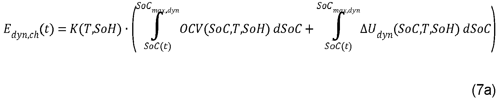

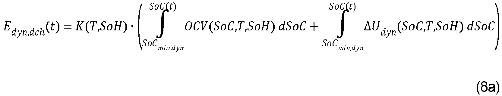

Applications Claiming Priority (1)
| Application Number | Priority Date | Filing Date | Title |
|---|---|---|---|
| DE102019212762.2A DE102019212762A1 (en) | 2019-08-26 | 2019-08-26 | Method for determining a power share, operating method, control unit, energy storage arrangement and power grid |
Publications (1)
| Publication Number | Publication Date |
|---|---|
| EP3787141A1 true EP3787141A1 (en) | 2021-03-03 |
Family
ID=71138521
Family Applications (1)
| Application Number | Title | Priority Date | Filing Date |
|---|---|---|---|
| EP20181618.8A Pending EP3787141A1 (en) | 2019-08-26 | 2020-06-23 | Method for determining a power component, operating method, control unit, energy storage assembly and power network |
Country Status (2)
| Country | Link |
|---|---|
| EP (1) | EP3787141A1 (en) |
| DE (1) | DE102019212762A1 (en) |
Cited By (1)
| Publication number | Priority date | Publication date | Assignee | Title |
|---|---|---|---|---|
| CN117698487A (en) * | 2024-02-05 | 2024-03-15 | 四川智能建造科技股份有限公司 | Dynamic scheduling method for electric energy of mobile charging and storing vehicle |
Citations (3)
| Publication number | Priority date | Publication date | Assignee | Title |
|---|---|---|---|---|
| DE102009049589A1 (en) | 2009-10-16 | 2011-04-21 | Bayerische Motoren Werke Aktiengesellschaft | Method for determining and / or predicting the maximum performance of a battery |
| US20170285111A1 (en) * | 2016-04-01 | 2017-10-05 | Demand Energy Networks, Inc. | Control systems and methods for economical optimization of an electrical system including battery degradation |
| WO2019049571A1 (en) * | 2017-09-11 | 2019-03-14 | パナソニックIpマネジメント株式会社 | Electricity storage system and management device |
Family Cites Families (3)
| Publication number | Priority date | Publication date | Assignee | Title |
|---|---|---|---|---|
| JP5472048B2 (en) * | 2010-11-10 | 2014-04-16 | 株式会社デンソー | In-vehicle secondary battery state quantification device |
| DE102013000572A1 (en) * | 2013-01-15 | 2014-07-17 | Rheinisch-Westfälische Technische Hochschule Aachen | Method for determining model parameters of electrochemical energy storage of e.g. electric vehicle, involves defining parameter record variant as new reference dataset to describe battery model and to determine maximum power of storage |
| DE102014210010A1 (en) * | 2014-05-26 | 2015-11-26 | Younicos Ag | Method and device for operating an electrical energy storage system |
-
2019
- 2019-08-26 DE DE102019212762.2A patent/DE102019212762A1/en active Pending
-
2020
- 2020-06-23 EP EP20181618.8A patent/EP3787141A1/en active Pending
Patent Citations (3)
| Publication number | Priority date | Publication date | Assignee | Title |
|---|---|---|---|---|
| DE102009049589A1 (en) | 2009-10-16 | 2011-04-21 | Bayerische Motoren Werke Aktiengesellschaft | Method for determining and / or predicting the maximum performance of a battery |
| US20170285111A1 (en) * | 2016-04-01 | 2017-10-05 | Demand Energy Networks, Inc. | Control systems and methods for economical optimization of an electrical system including battery degradation |
| WO2019049571A1 (en) * | 2017-09-11 | 2019-03-14 | パナソニックIpマネジメント株式会社 | Electricity storage system and management device |
Cited By (2)
| Publication number | Priority date | Publication date | Assignee | Title |
|---|---|---|---|---|
| CN117698487A (en) * | 2024-02-05 | 2024-03-15 | 四川智能建造科技股份有限公司 | Dynamic scheduling method for electric energy of mobile charging and storing vehicle |
| CN117698487B (en) * | 2024-02-05 | 2024-04-09 | 四川智能建造科技股份有限公司 | Dynamic scheduling method for electric energy of mobile charging and storing vehicle |
Also Published As
| Publication number | Publication date |
|---|---|
| DE102019212762A1 (en) | 2021-03-04 |
Similar Documents
| Publication | Publication Date | Title |
|---|---|---|
| DE102011116516B4 (en) | A method for determining a condition of a rechargeable battery device in real time | |
| EP3048687B1 (en) | Method for controlling an electrical energy distribution network | |
| EP1590679A1 (en) | State variable and parameter estimator comprising several partial models for an electrical energy storage device | |
| DE102017123184A1 (en) | Apparatus and method for charging an electrical energy storage system | |
| DE112017004673T5 (en) | Energy conversion device | |
| EP2777123A1 (en) | Method for providing control power for a power network | |
| DE102014002973A1 (en) | Method for charging batteries and converter for charging | |
| WO2017178057A1 (en) | Method and device for using an electrochemical energy store so as to optimize the service life | |
| EP3472889A1 (en) | Method and device for the use of an electrochemical energy storage device so as to optimize the service life | |
| EP3787141A1 (en) | Method for determining a power component, operating method, control unit, energy storage assembly and power network | |
| DE112019000212B4 (en) | Boosting a battery voltage with boost converters | |
| DE10103848A1 (en) | Determining and/or judging aging of battery by combination of selected operating parameters and /or battery states using fuzzy logic | |
| DE112022002486T5 (en) | ADJUSTMENT OF INVERTER TERMINAL VOLTAGE IN POWER SYSTEM | |
| DE102015114497A1 (en) | METHOD FOR OPERATING A VEHICLE DRIVE TRAIN ON THE BASIS OF A PREDICTION OF HOW PARALLEL SWITCHED BATTERIES USE DIFFERENT CHEMICALS TO PUBLISH A REQUIRED ELECTRICITY | |
| DE102021128152A1 (en) | POWER DISTRIBUTION DEVICE, POWER DISTRIBUTION METHOD AND PROGRAM | |
| DE10328055A1 (en) | State quantity and parameter estimators with several partial models for an electrical energy storage | |
| WO2013068233A2 (en) | Method for providing reserve power for stabilizing an alternating current network | |
| CH716792A2 (en) | Method and control device for operating a battery system and battery system. | |
| EP4002237A1 (en) | Method for distributing an electrical overall energy demand or storage request in a virtual power plant and a virtual power plant | |
| DE102015222683A1 (en) | Method for the computer-aided determination of parameters of an electrochemical energy store | |
| DE102019121774A1 (en) | Relay control for charging points | |
| DE102019217303A1 (en) | Method for operating a battery module, battery module for a motor vehicle and motor vehicle | |
| EP3682387A1 (en) | Controlling microgrids | |
| DE102021207381A1 (en) | Method for commissioning a DC-coupled large-scale storage system, computer program product, control device for a DC-coupled large-scale storage system, DC-coupled large-scale storage system and power grid with a DC-coupled large-scale storage system | |
| DE102014214863A1 (en) | Method for computer-aided control of power in an electric power grid |
Legal Events
| Date | Code | Title | Description |
|---|---|---|---|
| PUAI | Public reference made under article 153(3) epc to a published international application that has entered the european phase |
Free format text: ORIGINAL CODE: 0009012 |
|
| STAA | Information on the status of an ep patent application or granted ep patent |
Free format text: STATUS: THE APPLICATION HAS BEEN PUBLISHED |
|
| AK | Designated contracting states |
Kind code of ref document: A1 Designated state(s): AL AT BE BG CH CY CZ DE DK EE ES FI FR GB GR HR HU IE IS IT LI LT LU LV MC MK MT NL NO PL PT RO RS SE SI SK SM TR |
|
| AX | Request for extension of the european patent |
Extension state: BA ME |
|
| STAA | Information on the status of an ep patent application or granted ep patent |
Free format text: STATUS: REQUEST FOR EXAMINATION WAS MADE |
|
| 17P | Request for examination filed |
Effective date: 20210901 |
|
| RBV | Designated contracting states (corrected) |
Designated state(s): AL AT BE BG CH CY CZ DE DK EE ES FI FR GB GR HR HU IE IS IT LI LT LU LV MC MK MT NL NO PL PT RO RS SE SI SK SM TR |
|
| STAA | Information on the status of an ep patent application or granted ep patent |
Free format text: STATUS: EXAMINATION IS IN PROGRESS |
|
| 17Q | First examination report despatched |
Effective date: 20221025 |