EP3786567B1 - Wärmetauscher - Google Patents
Wärmetauscher Download PDFInfo
- Publication number
- EP3786567B1 EP3786567B1 EP19382728.4A EP19382728A EP3786567B1 EP 3786567 B1 EP3786567 B1 EP 3786567B1 EP 19382728 A EP19382728 A EP 19382728A EP 3786567 B1 EP3786567 B1 EP 3786567B1
- Authority
- EP
- European Patent Office
- Prior art keywords
- baffle
- housing
- inlet
- heat exchanger
- coolant
- Prior art date
- Legal status (The legal status is an assumption and is not a legal conclusion. Google has not performed a legal analysis and makes no representation as to the accuracy of the status listed.)
- Active
Links
Images


Classifications
-
- F—MECHANICAL ENGINEERING; LIGHTING; HEATING; WEAPONS; BLASTING
- F28—HEAT EXCHANGE IN GENERAL
- F28F—DETAILS OF HEAT-EXCHANGE AND HEAT-TRANSFER APPARATUS, OF GENERAL APPLICATION
- F28F9/00—Casings; Header boxes; Auxiliary supports for elements; Auxiliary members within casings
- F28F9/02—Header boxes; End plates
- F28F9/026—Header boxes; End plates with static flow control means, e.g. with means for uniformly distributing heat exchange media into conduits
- F28F9/028—Header boxes; End plates with static flow control means, e.g. with means for uniformly distributing heat exchange media into conduits by using inserts for modifying the pattern of flow inside the header box, e.g. by using flow restrictors or permeable bodies or blocks with channels
-
- F—MECHANICAL ENGINEERING; LIGHTING; HEATING; WEAPONS; BLASTING
- F28—HEAT EXCHANGE IN GENERAL
- F28D—HEAT-EXCHANGE APPARATUS, NOT PROVIDED FOR IN ANOTHER SUBCLASS, IN WHICH THE HEAT-EXCHANGE MEDIA DO NOT COME INTO DIRECT CONTACT
- F28D21/00—Heat-exchange apparatus not covered by any of the groups F28D1/00 - F28D20/00
- F28D21/0001—Recuperative heat exchangers
- F28D21/0003—Recuperative heat exchangers the heat being recuperated from exhaust gases
-
- F—MECHANICAL ENGINEERING; LIGHTING; HEATING; WEAPONS; BLASTING
- F28—HEAT EXCHANGE IN GENERAL
- F28D—HEAT-EXCHANGE APPARATUS, NOT PROVIDED FOR IN ANOTHER SUBCLASS, IN WHICH THE HEAT-EXCHANGE MEDIA DO NOT COME INTO DIRECT CONTACT
- F28D7/00—Heat-exchange apparatus having stationary tubular conduit assemblies for both heat-exchange media, the media being in contact with different sides of a conduit wall
- F28D7/16—Heat-exchange apparatus having stationary tubular conduit assemblies for both heat-exchange media, the media being in contact with different sides of a conduit wall the conduits being arranged in parallel spaced relation
- F28D7/1684—Heat-exchange apparatus having stationary tubular conduit assemblies for both heat-exchange media, the media being in contact with different sides of a conduit wall the conduits being arranged in parallel spaced relation the conduits having a non-circular cross-section
-
- F—MECHANICAL ENGINEERING; LIGHTING; HEATING; WEAPONS; BLASTING
- F28—HEAT EXCHANGE IN GENERAL
- F28F—DETAILS OF HEAT-EXCHANGE AND HEAT-TRANSFER APPARATUS, OF GENERAL APPLICATION
- F28F9/00—Casings; Header boxes; Auxiliary supports for elements; Auxiliary members within casings
- F28F9/02—Header boxes; End plates
- F28F9/026—Header boxes; End plates with static flow control means, e.g. with means for uniformly distributing heat exchange media into conduits
- F28F9/0265—Header boxes; End plates with static flow control means, e.g. with means for uniformly distributing heat exchange media into conduits by using guiding means or impingement means inside the header box
-
- F—MECHANICAL ENGINEERING; LIGHTING; HEATING; WEAPONS; BLASTING
- F28—HEAT EXCHANGE IN GENERAL
- F28F—DETAILS OF HEAT-EXCHANGE AND HEAT-TRANSFER APPARATUS, OF GENERAL APPLICATION
- F28F9/00—Casings; Header boxes; Auxiliary supports for elements; Auxiliary members within casings
- F28F9/02—Header boxes; End plates
- F28F9/026—Header boxes; End plates with static flow control means, e.g. with means for uniformly distributing heat exchange media into conduits
- F28F9/0282—Header boxes; End plates with static flow control means, e.g. with means for uniformly distributing heat exchange media into conduits by varying the geometry of conduit ends, e.g. by using inserts or attachments for modifying the pattern of flow at the conduit inlet or outlet
-
- F—MECHANICAL ENGINEERING; LIGHTING; HEATING; WEAPONS; BLASTING
- F28—HEAT EXCHANGE IN GENERAL
- F28D—HEAT-EXCHANGE APPARATUS, NOT PROVIDED FOR IN ANOTHER SUBCLASS, IN WHICH THE HEAT-EXCHANGE MEDIA DO NOT COME INTO DIRECT CONTACT
- F28D21/00—Heat-exchange apparatus not covered by any of the groups F28D1/00 - F28D20/00
- F28D2021/0019—Other heat exchangers for particular applications; Heat exchange systems not otherwise provided for
- F28D2021/008—Other heat exchangers for particular applications; Heat exchange systems not otherwise provided for for vehicles
- F28D2021/0082—Charged air coolers
-
- F—MECHANICAL ENGINEERING; LIGHTING; HEATING; WEAPONS; BLASTING
- F28—HEAT EXCHANGE IN GENERAL
- F28F—DETAILS OF HEAT-EXCHANGE AND HEAT-TRANSFER APPARATUS, OF GENERAL APPLICATION
- F28F9/00—Casings; Header boxes; Auxiliary supports for elements; Auxiliary members within casings
- F28F9/02—Header boxes; End plates
- F28F2009/0285—Other particular headers or end plates
- F28F2009/029—Other particular headers or end plates with increasing or decreasing cross-section, e.g. having conical shape
-
- F—MECHANICAL ENGINEERING; LIGHTING; HEATING; WEAPONS; BLASTING
- F28—HEAT EXCHANGE IN GENERAL
- F28F—DETAILS OF HEAT-EXCHANGE AND HEAT-TRANSFER APPARATUS, OF GENERAL APPLICATION
- F28F2275/00—Fastening; Joining
- F28F2275/12—Fastening; Joining by methods involving deformation of the elements
Definitions
- the present invention relates to a heat exchanger, particularly to a thermal management system for an Exhaust Gas Re-circulation (EGR) cooler.
- EGR Exhaust Gas Re-circulation
- An Exhaust Gas Re-circulation (EGR) cooler receives exhaust gases from an engine and cools the exhaust gases before the exhaust gases are re-circulated back to the engine's cylinder. By re-circulating the engine's exhaust gas back to the engine's cylinder, the peak in-cylinder temperatures are regulated, specifically lowered to reduce formation of NOx gases. The EGR cooler further reduces the combustion chamber temperature, thereby preventing valve clatter, detonation and further reduces NO x formation. As a result, the exhaust gas recirculation (EGR) system substantially reduces vehicle emissions to enable meeting stringent vehicular exhaust emission norms prevalent in most parts of the world.
- exhaust gas is received in a tank and from the tank the exhaust gas pass through heat exchange tubes received inside the housing, coolant is delivered by a coolant inlet pipe around the heat exchange tubes to cause heat exchange between the exhaust gas and the coolant, thereby resulting in cooling of the exhaust gas and reducing the temperature of the exhaust gas.
- the coolant inlet pipe is disposed at sidewall of the EGR cooler.
- the EGR cooler handles high temperature exhaust gases in the temperature range of 400 to 900 °C. Accordingly, temperatures at certain regions inside the EGR cooler, particularly, a gas inlet area of the heat exchange tubes that first comes into contact with the exhaust gas, exceeds acceptable limits and cause formation of hot spots.
- the coolant from the coolant inlet pipe is directed to the gas inlet area of the heat exchange tubes by using a baffle disposed inside the coolant inlet pipe to avoid high temperatures at the gas inlet area.
- a baffle extends inside the housing of the EGR cooler and interferes with the other components, particularly, components such as for example, heat exchange tubes disposed inside the housing of the EGR cooler.
- packaging of the baffle within limited space inside the coolant inlet pipe is a concern and such configuration of the baffle inside the coolant inlet pipe may restrict coolant flow through the coolant inlet pipe.
- conventional method of providing baffle for directing coolant to the gas inlet area through an inlet configured on the housing fails to effectively regulate distribution and velocity of coolant directed to the gas inlet area.
- the conventional baffle is a dedicated component and as such there are product costs, inventory costs and process costs associated with configuring the baffle.
- an EGR cooler configured with a baffle that effectively directs coolant to the gas inlet area of the EGR cooler, thereby preventing high temperature hot spots at the gas inlet area and that is capable of addressing issues such as boiling of coolant, durability issues and excessive thermo-dynamical stresses arising due to hot spots at the gas inlet area of the EGR cooler.
- an EGR cooler configured with a baffle that does not interfere with the other components, particularly, components such as for example heat exchange tubes disposed inside the housing of the EGR cooler.
- an EGR cooler configured with a baffle that effectively directs coolant to the gas inlet area, thereby preventing excessive temperatures and the problems associated with the excessive temperatures at the gas inlet area.
- an EGR cooler configured with a baffle that is configured by modifying an existing part of the EGR cooler, thereby reducing product and process costs associated with configuring the baffle. Still further there is a need for an EGR cooler configured with a baffle inside a diverging tank secured to a side of housing of the EGR cooler, wherein the baffle can be conveniently packaged without disrupting coolant flow to heat exchange tubes received inside the housing, particularly, the gas inlet area. Further, there is a need for an EGR cooler that exhibits extended service life, improved reliability and efficiency.
- An object of the present invention is to provide an EGR cooler that obviates the drawbacks associated with conventional methods for cooling a gas inlet area for an EGR cooler that fails to effectively regulate distribution and velocity of coolant directed to the gas inlet area.
- Another object of the present invention is to provide an EGR cooler configured with a baffle that effectively directs coolant to a gas inlet area of an EGR cooler to achieve efficient cooling of the gas inlet area thereby addressing issues such as boiling of coolant, durability issues and excessive thermo-dynamical stresses arising due to hot spots at the gas inlet area of the EGR cooler.
- Still another object of the present invention is to provide an EGR cooler configured with a baffle that does not interfere with the other components, particularly, components such as for example, heat exchange tubes disposed inside the housing of the EGR cooler.
- Yet another object of the present invention is to provide an EGR cooler that can be easily packaged and that do not interfere with the flow of coolant through the coolant inlet pipe.
- Still another object of the present invention is to provide an EGR cooler configured with a baffle that is configured by modifying an existing part of the EGR cooler, thereby reducing product, process and inventory costs associated with configuring the baffle.
- Yet another objective of the present invention is to provide an EGR cooler that exhibits extended service life, improved reliability and efficiency.
- some elements or parameters may be indexed, such as a first element and a second element.
- this indexation is only meant to differentiate and name elements which are similar but not identical. No idea of priority should be inferred from such indexation, as these terms may be switched without betraying the invention. Additionally, this indexation does not imply any order in mounting or use of the elements of the invention.
- a heat exchanger according to the present invention is disclosed in accordance with claim 1.
- the heat exchanger includes housing, a heat exchanger core, a diverging tank and at least one baffle.
- the heat exchanger core is received in the housing and includes heat exchange tubes that receive hot gas.
- the coolant is received in the housing and around the heat exchange tubes.
- the diverging tank is disposed at a side of the housing and is diverging towards the housing. The diverging tank connects a coolant inlet with the housing to enable fluid communication between the coolant inlet and an interior of the housing.
- At least a portion of the at least one baffle is disposed inside the diverging tank and divides an interior of the diverging tank into at least two volumes, wherein at least one volume is in fluid communication with the interior of the housing and the at least one baffle directs coolant flow to a gas inlet area inside the housing.
- the housing includes at least one inlet formed thereon for enabling fluid communication between the at least one volume of the diverging tank and the interior of the housing.
- the at least one baffle is integrally formed with the housing.
- the at least one baffle as well as the at least one inlet is formed by deforming a cut out portion of the housing that is integrally connected to the housing.
- the diverging tank includes a first opening connected to the coolant inlet and a second opening larger than the first opening and connected to the first opening, the second opening is so disposed with respect to said at least one inlet that said diverging tank covers said at least one inlet.
- the at least one inlet and the at least one baffle is at least half the dimension of the second opening.
- a base of the at least one baffle is disposed along at least a portion of a periphery of the at least one inlet.
- the at least one baffle forms an angle in the range of 20 to 70 degrees with respect to the side wall of the housing configured with the at least one inlet.
- the at least one baffle includes a plurality of tabs configured thereon to secure the at least one baffle inside the diverging tank.
- the at least one baffle includes lips configured along at least a portion of a periphery thereof to secure the at least one baffle inside the diverging tank.
- the at least one baffle includes a plurality of apertures formed thereon.
- the at least one baffle is of a shape selected from group of shapes comprising of rectangular, semi-circular and trapezoidal shape.
- the heat exchange tubes are axially extending along the housing and the gas inlet area is near a tank delivering hot gases to the heat exchange tubes, the at least one inlet is disposed upstream of gas inlet area in direction of coolant flow and the at least one baffle directs coolant to the gas inlet area via the at least one inlet.
- the present invention relates to a thermal management system for an Exhaust Gas Re-circulation (EGR) cooler, specifically to at least one baffle, hereafter simply referred to as a baffle disposed inside a diverging tank.
- EGR Exhaust Gas Re-circulation
- a diverging tank is disposed at a side wall of a housing of the EGR cooler and is in addition to tanks disposed at ends of the housing for delivering hot gases to and collecting hot gases from heat exchange tubes received inside the housing.
- the baffle acts as a partition and divides an interior of the diverging tank into at least two volumes, wherein at least one volume is in fluid communication with an interior of the housing and the baffle directs coolant to a gas inlet area of the heat exchange tubes received inside the housing of the EGR cooler.
- baffle of the present invention addresses issues such as boiling of coolant, durability issues and excessive thermo-dynamical stresses, arising due to hot spots forming at the gas inlet area of the EGR cooler.
- the baffle of the present invention is used for directing coolant directly to the gas inlet area of the EGR cooler.
- the baffle of the present invention is also applicable for any other applications, where coolant or any other fluid is required to be directed at a particular region inside any other system such as for example a region that is exposed to hot fluid and that is required to be cooled to address issues arising due to formation of hot spots.
- FIG. 1a and FIG. 1b illustrate a heat exchanger particularly, an EGR cooler 100 in accordance with an embodiment of the present invention.
- the EGR cooler 100 is configured with a diverging tank 30 disposed at a side wall 10a of a housing 10 of the EGR cooler 100, wherein the housing 10 receives a heat exchanger core 20.
- the diverging tank 30 is in addition to tanks (not illustrated) disposed at ends of the housing 10 for delivering hot gases to and collecting hot gases from a plurality of heat exchange tubes 22 received inside the housing 10.
- the diverging tank 30 is in fluid communication with a coolant inlet 12 at one end and the housing 10 at the other end, thereby enabling fluid communication between the coolant inlet 12 and an interior of the housing 10.
- the diverging tank 30 includes a baffle 14 that is at least partially received therein for directing coolant directly to a gas inlet area 16, such as for example portions of the heat exchange tubes 22 near inlet of the heat exchange tubes 22 and received inside the housing 10.
- the baffle 14 may also direct coolant to the areas adjacent to the gas inlet area 16 to prevent drawbacks associated with over-heating.
- the gas inlet area 16 is for example the portion of the heat exchange tubes 22 of the heat exchanger core 20 that first receive the exhaust gas and are first to come in contact with high temperature exhaust gases and as such is prone issues such as boiling of coolant, durability issues and excessive thermo-dynamical stresses arising due to formation of hot spots.
- the baffle 14 directing coolant to the gas inlet area 16 disposed inside the housing 10 of the EGR cooler 100, the formation of hot spots at the gas inlet area 16 of the EGR cooler 100 is prevented and issues arising due to hot spots forming at the gas inlet area 16 of the EGR cooler 100 are also avoided.
- the baffle 14 may extend sideways out of the diverging tank 30 but do not extend into the housing 10 and as such do not interfere with the heat exchanger core 20 disposed inside the housing 10.
- the heat exchange tubes 22 are axially extending along the housing 10 and the gas inlet area 16 is near the tank delivering hot gases to the heat exchange tubes 22, the at least one inlet 18 is disposed upstream of gas inlet area 16 in direction of coolant flow and the at least one baffle 14 directs coolant to the gas inlet area 16 via the at least one inlet 18.
- the housing 10 receives the heat exchanger core 20 connected to and disposed between a pair of headers disposed at the opposite ends of the housing 10.
- the heat exchanger core 20 includes the plurality of heat exchange tubes 22 that receive hot gas from the tank and through which the hot gas pass.
- the housing 10 further receives coolant around the heat exchange tubes 22 through the coolant inlet 12.
- Such an arrangement enables heat exchange between the hot gas flowing through the heat exchange tubes 22 and the coolant around the heat exchange tubes 22.
- the portion of the heat exchange tubes 22 that receives the exhaust gases and as such that first comes in contact with high temperature exhaust gases is the gas inlet area 16 that is prone to issues due to formation of hot spots.
- the diverging tank 30 is disposed at side of the housing 10 and is diverging towards the housing 10.
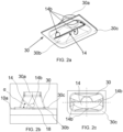
- the diverging tank 30 receives at least a portion of the baffle 14 as illustrated in FIG. 2a .
- the diverging tank 30 includes a first opening 30a connected to the coolant inlet 12 and a second opening 30b opposite to the first opening 30a, larger than the first opening 30a and connected to the first opening 30a by side walls of the diverging tank 30.
- the second opening 30b is further connected to the housing 10 along a flange 30c radially extending along the second opening 30b and as such the diverging tank 30 is diverging towards the housing 10.
- the diverging tank 30 is disposed between the coolant inlet 12 and the housing 10, the second opening 30b of the diverging tank 30 is so disposed with respect to at least one inlet 18 formed on the housing 10 for configuring fluid communication between the diverging tank 30 and the interior of the housing 10, that the diverging tank 30 covers the at least one inlet 18.
- the diverging tank 30 is in fluid communication with the coolant inlet 12 and the housing 10, thereby enabling fluid communication between the coolant inlet 12 and the interior of the housing 10.
- Such configuration of the diverging tank 30 provides enough space for receiving the baffle 14. Accordingly, such configuration of the diverging tank 30 receiving the baffle 14 enables the baffle 14 to direct the coolant from the coolant inlet 12 to the gas inlet area 16 without disrupting coolant flow to the gas inlet area 16.
- the baffle 14 is disposed inside the diverging tank 30 and acts as a partition to divide an interior of the diverging tank 30 into at least two volumes, wherein at least one volume is in fluid communication with the interior of the housing 10.
- the at least one baffle 14 forms an angle in the range of 20 to 70 degrees with respect to the side wall 10a of the housing 10 configured with the at least one inlet 18.
- FIG. 2a illustrates the baffle 14 configured with a plurality of tabs 14b for securing the baffle 14 to inner walls of the diverging tank 30.
- the baffle 14 can also be secured to the inner walls of the diverging tank 30 by using a plurality of lips 14d configured along at least a portion of periphery of the baffle 14 as illustrated in FIG. 4c .
- FIGS. 2b - 2c illustrate different views of the diverging tank 30 with the baffle 14 received and secured inside the diverging tank 30.
- FIGS. 2d and 2e illustrate different configurations of the baffle 14 received and secured inside the diverging tank 30, wherein the baffle 14 is illustrated in different orientations with respect to the inlet 18 configuring fluid communication between the interior of the diverging tank 30 and the interior of the housing 10.
- a base 14a of the baffle 14 is disposed along at least a periphery of the at least one inlet 18 and the baffle 14 can be at any angle, for example, angle " ⁇ " with the outside wall or the side wall 10a of the housing 10.
- the baffle 14 is at an acute angle with respect to the side wall 10a of the housing 10.
- the inlet 18 formed on the housing 10 can be of different dimensions "D1" and "D2".
- the inlet 18 and the baffle 14 is at least half the dimension of the second opening 30b.
- the orientation of the baffle 14 and the dimension of the inlet 18 formed on the housing 10 are based on the position of the gas inlet area 16 with respect to the inlet 18, and particularly, based on the direction in which the coolant is to be directed to reach the gas inlet area 16 and amount of coolant to be supplied to the gas inlet area 16 for effective cooling of the gas inlet area 16.
- the two volumes are in fluid communication with each other. Further at least one of the two volumes are in fluid communication with the interior of the housing 10 via at least one of the inlets 18. Specifically, both volumes are in fluid communication with the interior of the housing 10 via inlets 18 formed on the housing 10 and illustrated in FIG. 2f , wherein one inlet supplies coolant to the gas inlet area 16, such as for example portions of the heat exchange tubes 22 near the inlet of the heat exchange tubes 22, whereas the other inlet 18 supplies coolant to the remaining portion of the heat exchange tubes 22.
- the baffle 14 directs coolant to the gas inlet area 16 inside the housing 10 via one of the inlets 18.
- the baffle 14 is of a planar configuration.
- the baffle 14 is an integral part of the housing 10, particularly, integral part of the side wall 10a of the housing 10. More specifically, the at least one baffle 14 as well as the at least one inlet 18 is formed by deforming a cut out portion of the housing 10 that is still connected to the housing 10. The cut out portion of the housing 10 is cut along a profile and is configured by stamping operation such that the cut out portion is still connected to the side wall 10a of the housing 10 along at least one edge of the cut out portion, wherein when the cut out portion is lifted away from the side wall 10a to form the inlet 18 on the side wall 10a, the lifted cutout portion acts as the baffle 14.
- the baffle 14 can have different shapes such as rectangular, semi-circular and trapezoid shape, with at least one edge connected to the housing 10.
- the present invention is not limited to any particular shape of the cut out portion or the baffle 14 formed thereby and any particular method for forming the cut out portion until the cut out portion is capable of being deformed for forming the at least one baffle 14 as well as the at least one inlet 18 simultaneously.
- the at least one baffle 14 and the at least one inlet 18 are formed by a single step, thereby reducing the number of manufacturing steps required for configuring the diverging tank 30 secured to the housing 10 and with the at least one baffle 14 and the at least one inlet 18 received there inside.
- the baffle 14 in accordance of the present invention is formed by modifying an existing part of the EGR cooler, particularly, by modifying the housing 10, product, process and inventory costs associated with configuring the baffle as a dedicated element are eliminated. Further, with such configuration of the baffle 14, the baffle 14 is disposed inside the diverging tank 30 and does not interfere with the other components, particularly, components such as heat exchange tubes disposed inside the housing 10 of the EGR cooler 100. In accordance with another embodiment, the baffle 14 includes a plurality of apertures 14c configured thereon. The present invention is not limited to any particular placement of the apertures 14c on the baffle 14.
- the baffle 14 is formed by deforming the cut out portion of the housing 10, particularly, the cut out portion from the side wall 10a of the housing 10, such that the periphery of the cut out portion snugly fits with respect to inner walls of the diverging tank 30.
- the present invention is not limited to any particular shape, configuration and orientation of the baffle 14 inside the diverging tank 30 and method of forming the baffle 14 as far as the baffle 14 is capable of effectively directing coolant to the gas inlet area 16 disposed inside the housing 10.
- FIG. 3a illustrates the diverging tank 30 without the baffle 14 received there inside.
- FIG. 3b illustrates a sectional view of the diverging tank 30 along the section line A-A of FIG. 3a .
- the heat exchanger includes housing, a diverging tank and a baffle.
- the housing receives a heat exchanger core that includes heat exchange tubes that receives hot gas.
- the diverging tank is disposed at a side of the housing and is diverging towards the housing.
- the diverging tank connects a coolant inlet with the housing to enable fluid communication between the coolant inlet and an interior of the housing.
- the baffle is disposed inside the diverging tank and divides interior of the diverging tank into at least two volumes, wherein at least one volume is in fluid communication with the interior of the housing and the baffle directs coolant flow to a gas inlet area inside the housing.
Landscapes
- Engineering & Computer Science (AREA)
- Physics & Mathematics (AREA)
- Thermal Sciences (AREA)
- Mechanical Engineering (AREA)
- General Engineering & Computer Science (AREA)
- Geometry (AREA)
- Exhaust-Gas Circulating Devices (AREA)
- Heat-Exchange Devices With Radiators And Conduit Assemblies (AREA)
Claims (11)
- Wärmetauscher (100), umfassend:• ein Gehäuse (10);• einen Wärmetauscherkern (20), dazu angepasst, in dem Gehäuse (10) aufgenommen zu werden, und Wärmeaustauschrohre (22) umfassend, die dazu angepasst sind, heißes Gas aufzunehmen, wobei Kühlmittel in dem Gehäuse (10) und rund um die Wärmeaustauschrohre (22) aufgenommen ist;• einen auseinandergehenden Tank (30), angeordnet an einer Seite des Gehäuses (10) und in Richtung des Gehäuses (10) auseinandergehend, wobei der auseinandergehende Tank (30) dazu angepasst ist, einen Kühlmitteleinlass (12) mit dem Gehäuse (10) zu verbinden, um Fluidverbindung zwischen dem Kühlmitteleinlass (12) und einem Inneren des Gehäuses (10) zu ermöglichen; und• zumindest einen Teil zumindest eines Leitblechs (14), angeordnet im Inneren des auseinandergehenden Tanks (30) und dazu angepasst, ein Inneres des auseinandergehenden Tanks (30) in mindestens zwei Volumen zu teilen, wobei zumindest ein Volumen in Fluidverbindung mit dem Inneren des Gehäuses (10) ist und das zumindest eine Leitblech (14) dazu angepasst ist, Kühlmittelstrom zu einem Gaseinlassbereich (16) im Inneren des Gehäuses (10) zu leiten;dadurch gekennzeichnet, dass das zumindest eine Leitblech (14) integral mit dem Gehäuse (10) ausgebildet ist und wobei das zumindest eine Leitblech (14) sowie der zumindest eine Einlass durch Verformen eines Ausschnittteils des Gehäuses (10) gebildet sind, der integral mit dem Gehäuse (10) verbunden ist.
- Wärmetauscher (100) nach dem vorhergehenden Anspruch, wobei das Gehäuse (10) zumindest einen daran gebildeten Einlass (18) zum Ermöglichen von Fluidverbindung zwischen dem zumindest einen Volumen des auseinandergehenden Tanks (30) und dem Inneren des Gehäuses (10) umfasst.
- Wärmetauscher (100) nach Anspruch 2, wobei der auseinandergehende Tank (30) eine erste Öffnung (30a), die mit dem Kühlmitteleinlass (12) verbunden ist, und eine zweite Öffnung (30b), die größer als die erste Öffnung (30a) ist und mit der ersten Öffnung (30a) verbunden ist, umfasst, wobei die zweite Öffnung (30b) bezüglich des zumindest einen Einlasses (18) so angeordnet ist, dass der auseinandergehende Tank (30) den zumindest einen Einlass (18) abdeckt.
- Wärmetauscher (100) nach Anspruch 2, wobei der zumindest eine Einlass (18) und das zumindest eine Leitblech (14) zumindest die Hälfte der Abmessung der zweiten Öffnung (30b) aufweisen.
- Wärmetauscher (100) nach Anspruch 2, wobei eine Basis (14a) des zumindest einen Leitblechs (14) entlang zumindest eines Teils eines Umfangs des zumindest einen Einlasses (18) angeordnet ist.
- Wärmetauscher (100) nach dem vorhergehenden Anspruch, wobei das zumindest eine Leitblech (14) einen Winkel "α" im Bereich von 20 bis 70 Grad bezüglich einer Seitenwand (10a) des Gehäuses (10) bildet, die mit dem zumindest einen Einlass (18) ausgelegt ist.
- Wärmetauscher (100) nach einem der vorhergehenden Ansprüche, wobei das zumindest eine Leitblech (14) mehrere Nasen (14b) umfasst, die daran ausgelegt und dazu angepasst sind, das zumindest eine Leitblech (14) im Inneren des auseinandergehenden Tanks (30) zu sichern.
- Wärmetauscher (100) nach einem der vorhergehenden Ansprüche 1-6, wobei das zumindest eine Leitblech (14) Lippen (14d) umfasst, die entlang zumindest eines Teils eines Umfangs davon ausgebildet und dazu angepasst sind, das Leitblech (14) im Inneren des auseinandergehenden Tanks (30) zu sichern.
- Wärmetauscher (100) nach einem der vorhergehenden Ansprüche, wobei das zumindest eine Leitblech (14) ferner mehrere daran ausgebildete Öffnungen (14c) umfasst.
- Wärmetauscher (100) nach einem der vorhergehenden Ansprüche, wobei das zumindest eine Leitblech (14) eine Form aufweist, die aus einer Gruppe von Formen ausgewählt wird, die eine rechteckige, eine halbkreisförmige und eine trapezförmige Form umfasst.
- Wärmetauscher (100) nach einem des Anspruchs 2, wobei sich die Wärmeaustauschrohre (12) axial entlang des Gehäuses (10) erstrecken und der Gaseinlassbereich (16) nahe einem Tank ist, der heiße Gase zu den Wärmeaustauschrohren (22) zuführt, wobei der zumindest eine Einlass (18) dem Gaseinlassbereich (16) in Richtung des Kühlmittelflusses vorgelagert angeordnet ist und das zumindest eine Leitblech (14) dazu angepasst ist, Kühlmittel über den zumindest einen Einlass (18) zu dem Gaseinlassbereich (16) zu leiten.
Priority Applications (1)
| Application Number | Priority Date | Filing Date | Title |
|---|---|---|---|
| EP19382728.4A EP3786567B1 (de) | 2019-08-26 | 2019-08-26 | Wärmetauscher |
Applications Claiming Priority (1)
| Application Number | Priority Date | Filing Date | Title |
|---|---|---|---|
| EP19382728.4A EP3786567B1 (de) | 2019-08-26 | 2019-08-26 | Wärmetauscher |
Publications (2)
| Publication Number | Publication Date |
|---|---|
| EP3786567A1 EP3786567A1 (de) | 2021-03-03 |
| EP3786567B1 true EP3786567B1 (de) | 2024-11-20 |
Family
ID=67902441
Family Applications (1)
| Application Number | Title | Priority Date | Filing Date |
|---|---|---|---|
| EP19382728.4A Active EP3786567B1 (de) | 2019-08-26 | 2019-08-26 | Wärmetauscher |
Country Status (1)
| Country | Link |
|---|---|
| EP (1) | EP3786567B1 (de) |
Families Citing this family (1)
| Publication number | Priority date | Publication date | Assignee | Title |
|---|---|---|---|---|
| CN113883923B (zh) * | 2021-10-14 | 2024-10-11 | 浙江银轮机械股份有限公司 | 壳体、壳体组件及中冷器 |
Family Cites Families (5)
| Publication number | Priority date | Publication date | Assignee | Title |
|---|---|---|---|---|
| JP5988296B2 (ja) * | 2011-08-10 | 2016-09-07 | 臼井国際産業株式会社 | 多管式熱交換器 |
| DE102014202447A1 (de) * | 2014-02-11 | 2015-08-13 | MAHLE Behr GmbH & Co. KG | Abgaswärmeübertrager |
| DE102014119227A1 (de) * | 2014-12-19 | 2016-06-23 | Benteler Automobiltechnik Gmbh | Abgaswärmeübertrager |
| EP3246647B1 (de) * | 2016-05-19 | 2019-10-30 | Borgwarner Emissions Systems Spain, S.L.U. | Wärmetauschervorrichtung |
| DE102017219433B4 (de) * | 2017-10-30 | 2022-08-11 | Hanon Systems | Wärmeübertrager für einen Verbrennungsmotor |
-
2019
- 2019-08-26 EP EP19382728.4A patent/EP3786567B1/de active Active
Also Published As
| Publication number | Publication date |
|---|---|
| EP3786567A1 (de) | 2021-03-03 |
Similar Documents
| Publication | Publication Date | Title |
|---|---|---|
| EP2014892B1 (de) | Wärmetauscheranordnung | |
| EP3017177B1 (de) | Wärmetauscher für die kraftstoffzufuhr in einem verbrennungsmotor | |
| US9920686B2 (en) | Water-cooled charge air cooler with integrated multi-stage cooling | |
| KR20070112017A (ko) | 이중 냉각제 루프를 가지는 배기가스 재순환 쿨러 | |
| US7774937B2 (en) | Heat exchanger with divided coolant chamber | |
| US7703506B2 (en) | Exhaust heat exchanger | |
| US9732708B2 (en) | Internal combustion engine | |
| EP3017179B1 (de) | Wärmetauscher für die kraftstoffzufuhr in einem verbrennungsmotor | |
| US10954898B2 (en) | System for connecting housing elements of a device for heat transfer | |
| EP3786567B1 (de) | Wärmetauscher | |
| EP3567237B1 (de) | Wassermantelstruktur | |
| US9470187B2 (en) | EGR heat exchanger with continuous deaeration | |
| JP2015117631A (ja) | シリンダヘッド構造 | |
| EP4015976B1 (de) | Wärmetauscher | |
| EP3845852A1 (de) | Abgasrückführungskühler | |
| US11873073B2 (en) | Fuel cooled multi-function aperture | |
| KR102729471B1 (ko) | 열 교환기 | |
| JPH06101587A (ja) | 内燃機関の吸気マニホールド | |
| EP4306893A1 (de) | Wärmetauscherverteiler | |
| KR102123452B1 (ko) | 차량용 egr 쿨러 | |
| EP3786562B1 (de) | Abgasrückführungskühler | |
| JPH0742612A (ja) | 内燃機関のシリンダヘッド | |
| CN223305850U (zh) | 发动机缸盖、发动机和车辆 | |
| EP4253751B1 (de) | Agr-vorrichtung für einen verbrennungsmotor | |
| EP3741985A1 (de) | Kühler mit abgasrückführung (agr) |
Legal Events
| Date | Code | Title | Description |
|---|---|---|---|
| PUAI | Public reference made under article 153(3) epc to a published international application that has entered the european phase |
Free format text: ORIGINAL CODE: 0009012 |
|
| STAA | Information on the status of an ep patent application or granted ep patent |
Free format text: STATUS: THE APPLICATION HAS BEEN PUBLISHED |
|
| AK | Designated contracting states |
Kind code of ref document: A1 Designated state(s): AL AT BE BG CH CY CZ DE DK EE ES FI FR GB GR HR HU IE IS IT LI LT LU LV MC MK MT NL NO PL PT RO RS SE SI SK SM TR |
|
| AX | Request for extension of the european patent |
Extension state: BA ME |
|
| STAA | Information on the status of an ep patent application or granted ep patent |
Free format text: STATUS: REQUEST FOR EXAMINATION WAS MADE |
|
| 17P | Request for examination filed |
Effective date: 20210823 |
|
| RBV | Designated contracting states (corrected) |
Designated state(s): AL AT BE BG CH CY CZ DE DK EE ES FI FR GB GR HR HU IE IS IT LI LT LU LV MC MK MT NL NO PL PT RO RS SE SI SK SM TR |
|
| STAA | Information on the status of an ep patent application or granted ep patent |
Free format text: STATUS: EXAMINATION IS IN PROGRESS |
|
| 17Q | First examination report despatched |
Effective date: 20230510 |
|
| P01 | Opt-out of the competence of the unified patent court (upc) registered |
Effective date: 20230603 |
|
| GRAP | Despatch of communication of intention to grant a patent |
Free format text: ORIGINAL CODE: EPIDOSNIGR1 |
|
| STAA | Information on the status of an ep patent application or granted ep patent |
Free format text: STATUS: GRANT OF PATENT IS INTENDED |
|
| RAP3 | Party data changed (applicant data changed or rights of an application transferred) |
Owner name: VALEO TERMICO, S.A. |
|
| INTG | Intention to grant announced |
Effective date: 20240724 |
|
| GRAS | Grant fee paid |
Free format text: ORIGINAL CODE: EPIDOSNIGR3 |
|
| GRAA | (expected) grant |
Free format text: ORIGINAL CODE: 0009210 |
|
| STAA | Information on the status of an ep patent application or granted ep patent |
Free format text: STATUS: THE PATENT HAS BEEN GRANTED |
|
| AK | Designated contracting states |
Kind code of ref document: B1 Designated state(s): AL AT BE BG CH CY CZ DE DK EE ES FI FR GB GR HR HU IE IS IT LI LT LU LV MC MK MT NL NO PL PT RO RS SE SI SK SM TR |
|
| REG | Reference to a national code |
Ref country code: GB Ref legal event code: FG4D |
|
| REG | Reference to a national code |
Ref country code: CH Ref legal event code: EP |
|
| REG | Reference to a national code |
Ref country code: DE Ref legal event code: R096 Ref document number: 602019062175 Country of ref document: DE |
|
| REG | Reference to a national code |
Ref country code: IE Ref legal event code: FG4D |
|
| REG | Reference to a national code |
Ref country code: LT Ref legal event code: MG9D |
|
| REG | Reference to a national code |
Ref country code: NL Ref legal event code: MP Effective date: 20241120 |
|
| PG25 | Lapsed in a contracting state [announced via postgrant information from national office to epo] |
Ref country code: PT Free format text: LAPSE BECAUSE OF FAILURE TO SUBMIT A TRANSLATION OF THE DESCRIPTION OR TO PAY THE FEE WITHIN THE PRESCRIBED TIME-LIMIT Effective date: 20250320 Ref country code: IS Free format text: LAPSE BECAUSE OF FAILURE TO SUBMIT A TRANSLATION OF THE DESCRIPTION OR TO PAY THE FEE WITHIN THE PRESCRIBED TIME-LIMIT Effective date: 20250320 Ref country code: HR Free format text: LAPSE BECAUSE OF FAILURE TO SUBMIT A TRANSLATION OF THE DESCRIPTION OR TO PAY THE FEE WITHIN THE PRESCRIBED TIME-LIMIT Effective date: 20241120 |
|
| PG25 | Lapsed in a contracting state [announced via postgrant information from national office to epo] |
Ref country code: FI Free format text: LAPSE BECAUSE OF FAILURE TO SUBMIT A TRANSLATION OF THE DESCRIPTION OR TO PAY THE FEE WITHIN THE PRESCRIBED TIME-LIMIT Effective date: 20241120 Ref country code: NL Free format text: LAPSE BECAUSE OF FAILURE TO SUBMIT A TRANSLATION OF THE DESCRIPTION OR TO PAY THE FEE WITHIN THE PRESCRIBED TIME-LIMIT Effective date: 20241120 |
|
| REG | Reference to a national code |
Ref country code: AT Ref legal event code: MK05 Ref document number: 1743912 Country of ref document: AT Kind code of ref document: T Effective date: 20241120 |
|
| PG25 | Lapsed in a contracting state [announced via postgrant information from national office to epo] |
Ref country code: BG Free format text: LAPSE BECAUSE OF FAILURE TO SUBMIT A TRANSLATION OF THE DESCRIPTION OR TO PAY THE FEE WITHIN THE PRESCRIBED TIME-LIMIT Effective date: 20241120 |
|
| PG25 | Lapsed in a contracting state [announced via postgrant information from national office to epo] |
Ref country code: ES Free format text: LAPSE BECAUSE OF FAILURE TO SUBMIT A TRANSLATION OF THE DESCRIPTION OR TO PAY THE FEE WITHIN THE PRESCRIBED TIME-LIMIT Effective date: 20241120 |
|
| PG25 | Lapsed in a contracting state [announced via postgrant information from national office to epo] |
Ref country code: NO Free format text: LAPSE BECAUSE OF FAILURE TO SUBMIT A TRANSLATION OF THE DESCRIPTION OR TO PAY THE FEE WITHIN THE PRESCRIBED TIME-LIMIT Effective date: 20250220 |
|
| PG25 | Lapsed in a contracting state [announced via postgrant information from national office to epo] |
Ref country code: LV Free format text: LAPSE BECAUSE OF FAILURE TO SUBMIT A TRANSLATION OF THE DESCRIPTION OR TO PAY THE FEE WITHIN THE PRESCRIBED TIME-LIMIT Effective date: 20241120 Ref country code: GR Free format text: LAPSE BECAUSE OF FAILURE TO SUBMIT A TRANSLATION OF THE DESCRIPTION OR TO PAY THE FEE WITHIN THE PRESCRIBED TIME-LIMIT Effective date: 20250221 Ref country code: AT Free format text: LAPSE BECAUSE OF FAILURE TO SUBMIT A TRANSLATION OF THE DESCRIPTION OR TO PAY THE FEE WITHIN THE PRESCRIBED TIME-LIMIT Effective date: 20241120 |
|
| PG25 | Lapsed in a contracting state [announced via postgrant information from national office to epo] |
Ref country code: PL Free format text: LAPSE BECAUSE OF FAILURE TO SUBMIT A TRANSLATION OF THE DESCRIPTION OR TO PAY THE FEE WITHIN THE PRESCRIBED TIME-LIMIT Effective date: 20241120 |
|
| PG25 | Lapsed in a contracting state [announced via postgrant information from national office to epo] |
Ref country code: RS Free format text: LAPSE BECAUSE OF FAILURE TO SUBMIT A TRANSLATION OF THE DESCRIPTION OR TO PAY THE FEE WITHIN THE PRESCRIBED TIME-LIMIT Effective date: 20250220 |
|
| PG25 | Lapsed in a contracting state [announced via postgrant information from national office to epo] |
Ref country code: SM Free format text: LAPSE BECAUSE OF FAILURE TO SUBMIT A TRANSLATION OF THE DESCRIPTION OR TO PAY THE FEE WITHIN THE PRESCRIBED TIME-LIMIT Effective date: 20241120 |
|
| PG25 | Lapsed in a contracting state [announced via postgrant information from national office to epo] |
Ref country code: DK Free format text: LAPSE BECAUSE OF FAILURE TO SUBMIT A TRANSLATION OF THE DESCRIPTION OR TO PAY THE FEE WITHIN THE PRESCRIBED TIME-LIMIT Effective date: 20241120 |
|
| PG25 | Lapsed in a contracting state [announced via postgrant information from national office to epo] |
Ref country code: EE Free format text: LAPSE BECAUSE OF FAILURE TO SUBMIT A TRANSLATION OF THE DESCRIPTION OR TO PAY THE FEE WITHIN THE PRESCRIBED TIME-LIMIT Effective date: 20241120 |
|
| PG25 | Lapsed in a contracting state [announced via postgrant information from national office to epo] |
Ref country code: RO Free format text: LAPSE BECAUSE OF FAILURE TO SUBMIT A TRANSLATION OF THE DESCRIPTION OR TO PAY THE FEE WITHIN THE PRESCRIBED TIME-LIMIT Effective date: 20241120 |
|
| PG25 | Lapsed in a contracting state [announced via postgrant information from national office to epo] |
Ref country code: SK Free format text: LAPSE BECAUSE OF FAILURE TO SUBMIT A TRANSLATION OF THE DESCRIPTION OR TO PAY THE FEE WITHIN THE PRESCRIBED TIME-LIMIT Effective date: 20241120 |
|
| PG25 | Lapsed in a contracting state [announced via postgrant information from national office to epo] |
Ref country code: CZ Free format text: LAPSE BECAUSE OF FAILURE TO SUBMIT A TRANSLATION OF THE DESCRIPTION OR TO PAY THE FEE WITHIN THE PRESCRIBED TIME-LIMIT Effective date: 20241120 |
|
| PG25 | Lapsed in a contracting state [announced via postgrant information from national office to epo] |
Ref country code: IT Free format text: LAPSE BECAUSE OF FAILURE TO SUBMIT A TRANSLATION OF THE DESCRIPTION OR TO PAY THE FEE WITHIN THE PRESCRIBED TIME-LIMIT Effective date: 20241120 |
|
| REG | Reference to a national code |
Ref country code: DE Ref legal event code: R097 Ref document number: 602019062175 Country of ref document: DE |
|
| PG25 | Lapsed in a contracting state [announced via postgrant information from national office to epo] |
Ref country code: SE Free format text: LAPSE BECAUSE OF FAILURE TO SUBMIT A TRANSLATION OF THE DESCRIPTION OR TO PAY THE FEE WITHIN THE PRESCRIBED TIME-LIMIT Effective date: 20241120 |
|
| PLBE | No opposition filed within time limit |
Free format text: ORIGINAL CODE: 0009261 |
|
| STAA | Information on the status of an ep patent application or granted ep patent |
Free format text: STATUS: NO OPPOSITION FILED WITHIN TIME LIMIT |
|
| PGFP | Annual fee paid to national office [announced via postgrant information from national office to epo] |
Ref country code: DE Payment date: 20250812 Year of fee payment: 7 |
|
| PGFP | Annual fee paid to national office [announced via postgrant information from national office to epo] |
Ref country code: FR Payment date: 20250828 Year of fee payment: 7 |
|
| 26N | No opposition filed |
Effective date: 20250821 |
|
| REG | Reference to a national code |
Ref country code: CH Ref legal event code: H13 Free format text: ST27 STATUS EVENT CODE: U-0-0-H10-H13 (AS PROVIDED BY THE NATIONAL OFFICE) Effective date: 20260324 |
|
| PG25 | Lapsed in a contracting state [announced via postgrant information from national office to epo] |
Ref country code: MC Free format text: LAPSE BECAUSE OF FAILURE TO SUBMIT A TRANSLATION OF THE DESCRIPTION OR TO PAY THE FEE WITHIN THE PRESCRIBED TIME-LIMIT Effective date: 20241120 |
|
| PG25 | Lapsed in a contracting state [announced via postgrant information from national office to epo] |
Ref country code: LU Free format text: LAPSE BECAUSE OF NON-PAYMENT OF DUE FEES Effective date: 20250826 |
|
| PG25 | Lapsed in a contracting state [announced via postgrant information from national office to epo] |
Ref country code: CH Free format text: LAPSE BECAUSE OF NON-PAYMENT OF DUE FEES Effective date: 20250831 |