EP3786557B1 - Method of drying electrode assemblies - Google Patents
Method of drying electrode assemblies Download PDFInfo
- Publication number
- EP3786557B1 EP3786557B1 EP20201984.0A EP20201984A EP3786557B1 EP 3786557 B1 EP3786557 B1 EP 3786557B1 EP 20201984 A EP20201984 A EP 20201984A EP 3786557 B1 EP3786557 B1 EP 3786557B1
- Authority
- EP
- European Patent Office
- Prior art keywords
- ppm
- electrode assembly
- less
- cathode
- electrode
- Prior art date
- Legal status (The legal status is an assumption and is not a legal conclusion. Google has not performed a legal analysis and makes no representation as to the accuracy of the status listed.)
- Active
Links
- 238000001035 drying Methods 0.000 title claims description 122
- 238000000034 method Methods 0.000 title claims description 96
- 230000000712 assembly Effects 0.000 title description 5
- 238000000429 assembly Methods 0.000 title description 5
- XLYOFNOQVPJJNP-UHFFFAOYSA-N water Substances O XLYOFNOQVPJJNP-UHFFFAOYSA-N 0.000 claims description 106
- 229910001868 water Inorganic materials 0.000 claims description 96
- -1 polyethylene Polymers 0.000 claims description 68
- 239000011230 binding agent Substances 0.000 claims description 40
- 239000000463 material Substances 0.000 claims description 33
- 239000011261 inert gas Substances 0.000 claims description 26
- 239000002033 PVDF binder Substances 0.000 claims description 25
- 229920002981 polyvinylidene fluoride Polymers 0.000 claims description 25
- 229920002125 Sokalan® Polymers 0.000 claims description 19
- 229920000139 polyethylene terephthalate Polymers 0.000 claims description 19
- 239000005020 polyethylene terephthalate Substances 0.000 claims description 19
- 229920003048 styrene butadiene rubber Polymers 0.000 claims description 19
- 239000011267 electrode slurry Substances 0.000 claims description 18
- 238000011049 filling Methods 0.000 claims description 18
- 239000004698 Polyethylene Substances 0.000 claims description 17
- 229920000573 polyethylene Polymers 0.000 claims description 17
- 239000004642 Polyimide Substances 0.000 claims description 16
- 229920001721 polyimide Polymers 0.000 claims description 16
- 229920002239 polyacrylonitrile Polymers 0.000 claims description 15
- 239000000835 fiber Substances 0.000 claims description 14
- 229920002134 Carboxymethyl cellulose Polymers 0.000 claims description 13
- 235000010948 carboxy methyl cellulose Nutrition 0.000 claims description 13
- 229920001577 copolymer Polymers 0.000 claims description 13
- 239000003960 organic solvent Substances 0.000 claims description 13
- 239000004743 Polypropylene Substances 0.000 claims description 11
- 229920001155 polypropylene Polymers 0.000 claims description 11
- 239000004952 Polyamide Substances 0.000 claims description 8
- 239000004721 Polyphenylene oxide Substances 0.000 claims description 8
- 239000000783 alginic acid Substances 0.000 claims description 8
- 229920000615 alginic acid Polymers 0.000 claims description 8
- 235000010443 alginic acid Nutrition 0.000 claims description 8
- 229960001126 alginic acid Drugs 0.000 claims description 8
- 150000004781 alginic acids Chemical class 0.000 claims description 8
- 229920001971 elastomer Polymers 0.000 claims description 8
- 229920002647 polyamide Polymers 0.000 claims description 8
- 229920006324 polyoxymethylene Polymers 0.000 claims description 8
- 239000005060 rubber Substances 0.000 claims description 8
- 150000003839 salts Chemical class 0.000 claims description 8
- 229920000459 Nitrile rubber Polymers 0.000 claims description 7
- 239000001768 carboxy methyl cellulose Substances 0.000 claims description 7
- 239000008112 carboxymethyl-cellulose Substances 0.000 claims description 7
- 239000004584 polyacrylic acid Substances 0.000 claims description 7
- 229920000728 polyester Polymers 0.000 claims description 7
- 229920000642 polymer Polymers 0.000 claims description 7
- 229920000036 polyvinylpyrrolidone Polymers 0.000 claims description 7
- 239000001267 polyvinylpyrrolidone Substances 0.000 claims description 7
- 235000013855 polyvinylpyrrolidone Nutrition 0.000 claims description 7
- 239000004816 latex Substances 0.000 claims description 6
- 229920000126 latex Polymers 0.000 claims description 6
- 229920001343 polytetrafluoroethylene Polymers 0.000 claims description 6
- 239000004810 polytetrafluoroethylene Substances 0.000 claims description 6
- 239000004696 Poly ether ether ketone Substances 0.000 claims description 5
- 229930182556 Polyacetal Natural products 0.000 claims description 5
- 239000004734 Polyphenylene sulfide Substances 0.000 claims description 5
- 239000004699 Ultra-high molecular weight polyethylene Substances 0.000 claims description 5
- HQQADJVZYDDRJT-UHFFFAOYSA-N ethene;prop-1-ene Chemical group C=C.CC=C HQQADJVZYDDRJT-UHFFFAOYSA-N 0.000 claims description 5
- 229920001903 high density polyethylene Polymers 0.000 claims description 5
- 239000004700 high-density polyethylene Substances 0.000 claims description 5
- 229920000092 linear low density polyethylene Polymers 0.000 claims description 5
- 239000004707 linear low-density polyethylene Substances 0.000 claims description 5
- 229920001684 low density polyethylene Polymers 0.000 claims description 5
- 239000004702 low-density polyethylene Substances 0.000 claims description 5
- 229920000515 polycarbonate Polymers 0.000 claims description 5
- 239000004417 polycarbonate Substances 0.000 claims description 5
- 229920002530 polyetherether ketone Polymers 0.000 claims description 5
- 229920006380 polyphenylene oxide Polymers 0.000 claims description 5
- 229920000069 polyphenylene sulfide Polymers 0.000 claims description 5
- 229920000785 ultra high molecular weight polyethylene Polymers 0.000 claims description 5
- 239000004925 Acrylic resin Substances 0.000 claims description 4
- 229920000178 Acrylic resin Polymers 0.000 claims description 4
- YCKRFDGAMUMZLT-UHFFFAOYSA-N Fluorine atom Chemical compound [F] YCKRFDGAMUMZLT-UHFFFAOYSA-N 0.000 claims description 4
- 229920002153 Hydroxypropyl cellulose Polymers 0.000 claims description 4
- 229920003171 Poly (ethylene oxide) Polymers 0.000 claims description 4
- 239000005062 Polybutadiene Substances 0.000 claims description 4
- 239000004793 Polystyrene Substances 0.000 claims description 4
- 239000004372 Polyvinyl alcohol Substances 0.000 claims description 4
- 229920005993 acrylate styrene-butadiene rubber polymer Polymers 0.000 claims description 4
- 229920005549 butyl rubber Polymers 0.000 claims description 4
- 239000011248 coating agent Substances 0.000 claims description 4
- 238000000576 coating method Methods 0.000 claims description 4
- 239000003822 epoxy resin Substances 0.000 claims description 4
- 239000011737 fluorine Substances 0.000 claims description 4
- 229910052731 fluorine Inorganic materials 0.000 claims description 4
- LNEPOXFFQSENCJ-UHFFFAOYSA-N haloperidol Chemical compound C1CC(O)(C=2C=CC(Cl)=CC=2)CCN1CCCC(=O)C1=CC=C(F)C=C1 LNEPOXFFQSENCJ-UHFFFAOYSA-N 0.000 claims description 4
- 239000001863 hydroxypropyl cellulose Substances 0.000 claims description 4
- 235000010977 hydroxypropyl cellulose Nutrition 0.000 claims description 4
- 229920002681 hypalon Polymers 0.000 claims description 4
- 239000005011 phenolic resin Substances 0.000 claims description 4
- 229920001568 phenolic resin Polymers 0.000 claims description 4
- 229920002755 poly(epichlorohydrin) Polymers 0.000 claims description 4
- 229920002627 poly(phosphazenes) Polymers 0.000 claims description 4
- 229920002857 polybutadiene Polymers 0.000 claims description 4
- 229920000647 polyepoxide Polymers 0.000 claims description 4
- 229920002223 polystyrene Polymers 0.000 claims description 4
- 229920002451 polyvinyl alcohol Polymers 0.000 claims description 4
- 229920002717 polyvinylpyridine Polymers 0.000 claims description 4
- 238000012545 processing Methods 0.000 claims description 4
- KXJGSNRAQWDDJT-UHFFFAOYSA-N 1-acetyl-5-bromo-2h-indol-3-one Chemical compound BrC1=CC=C2N(C(=O)C)CC(=O)C2=C1 KXJGSNRAQWDDJT-UHFFFAOYSA-N 0.000 claims description 3
- XCKPLVGWGCWOMD-YYEYMFTQSA-N 3-[[(2r,3r,4s,5r,6r)-6-[(2s,3s,4r,5r)-3,4-bis(2-cyanoethoxy)-2,5-bis(2-cyanoethoxymethyl)oxolan-2-yl]oxy-3,4,5-tris(2-cyanoethoxy)oxan-2-yl]methoxy]propanenitrile Chemical compound N#CCCO[C@H]1[C@H](OCCC#N)[C@@H](COCCC#N)O[C@@]1(COCCC#N)O[C@@H]1[C@H](OCCC#N)[C@@H](OCCC#N)[C@H](OCCC#N)[C@@H](COCCC#N)O1 XCKPLVGWGCWOMD-YYEYMFTQSA-N 0.000 claims description 3
- 229920008347 Cellulose acetate propionate Polymers 0.000 claims description 3
- 229930040373 Paraformaldehyde Natural products 0.000 claims description 3
- 229920002845 Poly(methacrylic acid) Polymers 0.000 claims description 3
- 239000002253 acid Substances 0.000 claims description 3
- XECAHXYUAAWDEL-UHFFFAOYSA-N acrylonitrile butadiene styrene Chemical compound C=CC=C.C=CC#N.C=CC1=CC=CC=C1 XECAHXYUAAWDEL-UHFFFAOYSA-N 0.000 claims description 3
- 229920002301 cellulose acetate Polymers 0.000 claims description 3
- 229920006217 cellulose acetate butyrate Polymers 0.000 claims description 3
- 229920002313 fluoropolymer Polymers 0.000 claims description 3
- 229920002492 poly(sulfone) Polymers 0.000 claims description 3
- 229920002401 polyacrylamide Polymers 0.000 claims description 3
- 229920000058 polyacrylate Polymers 0.000 claims description 3
- 229920001748 polybutylene Polymers 0.000 claims description 3
- 229920001707 polybutylene terephthalate Polymers 0.000 claims description 3
- 229920005646 polycarboxylate Polymers 0.000 claims description 3
- 229920000570 polyether Polymers 0.000 claims description 3
- 229920000193 polymethacrylate Polymers 0.000 claims description 3
- 229920000098 polyolefin Polymers 0.000 claims description 3
- 229920002635 polyurethane Polymers 0.000 claims description 3
- 239000004814 polyurethane Substances 0.000 claims description 3
- 229920002689 polyvinyl acetate Polymers 0.000 claims description 3
- 239000011118 polyvinyl acetate Substances 0.000 claims description 3
- 229920001774 Perfluoroether Polymers 0.000 claims description 2
- 230000000052 comparative effect Effects 0.000 description 33
- 239000002002 slurry Substances 0.000 description 26
- 239000006258 conductive agent Substances 0.000 description 25
- 239000007789 gas Substances 0.000 description 24
- OKTJSMMVPCPJKN-UHFFFAOYSA-N Carbon Chemical compound [C] OKTJSMMVPCPJKN-UHFFFAOYSA-N 0.000 description 22
- 239000010408 film Substances 0.000 description 22
- 229910052799 carbon Inorganic materials 0.000 description 18
- SECXISVLQFMRJM-UHFFFAOYSA-N N-Methylpyrrolidone Chemical compound CN1CCCC1=O SECXISVLQFMRJM-UHFFFAOYSA-N 0.000 description 16
- 238000007599 discharging Methods 0.000 description 16
- PXHVJJICTQNCMI-UHFFFAOYSA-N Nickel Chemical compound [Ni] PXHVJJICTQNCMI-UHFFFAOYSA-N 0.000 description 15
- 239000010406 cathode material Substances 0.000 description 15
- 238000002360 preparation method Methods 0.000 description 15
- 238000012546 transfer Methods 0.000 description 15
- 229910052782 aluminium Inorganic materials 0.000 description 14
- 238000002848 electrochemical method Methods 0.000 description 14
- RYGMFSIKBFXOCR-UHFFFAOYSA-N Copper Chemical compound [Cu] RYGMFSIKBFXOCR-UHFFFAOYSA-N 0.000 description 13
- XAGFODPZIPBFFR-UHFFFAOYSA-N aluminium Chemical compound [Al] XAGFODPZIPBFFR-UHFFFAOYSA-N 0.000 description 13
- 239000006229 carbon black Substances 0.000 description 12
- 239000011888 foil Substances 0.000 description 12
- 238000004519 manufacturing process Methods 0.000 description 12
- 238000001291 vacuum drying Methods 0.000 description 12
- HBBGRARXTFLTSG-UHFFFAOYSA-N Lithium ion Chemical compound [Li+] HBBGRARXTFLTSG-UHFFFAOYSA-N 0.000 description 10
- 239000011889 copper foil Substances 0.000 description 10
- 229910001416 lithium ion Inorganic materials 0.000 description 10
- 239000012982 microporous membrane Substances 0.000 description 10
- 238000002156 mixing Methods 0.000 description 10
- 230000000717 retained effect Effects 0.000 description 10
- 239000007787 solid Substances 0.000 description 10
- IJGRMHOSHXDMSA-UHFFFAOYSA-N Atomic nitrogen Chemical compound N#N IJGRMHOSHXDMSA-UHFFFAOYSA-N 0.000 description 9
- 239000002174 Styrene-butadiene Substances 0.000 description 9
- 230000001351 cycling effect Effects 0.000 description 9
- 239000008367 deionised water Substances 0.000 description 9
- 229910021641 deionized water Inorganic materials 0.000 description 9
- 239000002904 solvent Substances 0.000 description 9
- 239000011800 void material Substances 0.000 description 9
- XKRFYHLGVUSROY-UHFFFAOYSA-N Argon Chemical compound [Ar] XKRFYHLGVUSROY-UHFFFAOYSA-N 0.000 description 8
- 239000007772 electrode material Substances 0.000 description 8
- 239000003792 electrolyte Substances 0.000 description 8
- 238000007602 hot air drying Methods 0.000 description 8
- 238000012360 testing method Methods 0.000 description 8
- 229910032387 LiCoO2 Inorganic materials 0.000 description 7
- 229910052493 LiFePO4 Inorganic materials 0.000 description 7
- 239000010405 anode material Substances 0.000 description 7
- 229910052759 nickel Inorganic materials 0.000 description 7
- WEVYAHXRMPXWCK-UHFFFAOYSA-N Acetonitrile Chemical compound CC#N WEVYAHXRMPXWCK-UHFFFAOYSA-N 0.000 description 6
- UHOVQNZJYSORNB-UHFFFAOYSA-N Benzene Chemical compound C1=CC=CC=C1 UHOVQNZJYSORNB-UHFFFAOYSA-N 0.000 description 6
- RTZKZFJDLAIYFH-UHFFFAOYSA-N Diethyl ether Chemical compound CCOCC RTZKZFJDLAIYFH-UHFFFAOYSA-N 0.000 description 6
- 229910002097 Lithium manganese(III,IV) oxide Inorganic materials 0.000 description 6
- ZMXDDKWLCZADIW-UHFFFAOYSA-N N,N-Dimethylformamide Chemical compound CN(C)C=O ZMXDDKWLCZADIW-UHFFFAOYSA-N 0.000 description 6
- 239000006182 cathode active material Substances 0.000 description 6
- 229920006184 cellulose methylcellulose Polymers 0.000 description 6
- 229910052744 lithium Inorganic materials 0.000 description 6
- 238000003860 storage Methods 0.000 description 6
- 229910003005 LiNiO2 Inorganic materials 0.000 description 5
- 238000005520 cutting process Methods 0.000 description 5
- 229910021385 hard carbon Inorganic materials 0.000 description 5
- 238000010438 heat treatment Methods 0.000 description 5
- 239000004745 nonwoven fabric Substances 0.000 description 5
- 239000003921 oil Substances 0.000 description 5
- 238000003756 stirring Methods 0.000 description 5
- QGJOPFRUJISHPQ-UHFFFAOYSA-N Carbon disulfide Chemical compound S=C=S QGJOPFRUJISHPQ-UHFFFAOYSA-N 0.000 description 4
- HEDRZPFGACZZDS-UHFFFAOYSA-N Chloroform Chemical compound ClC(Cl)Cl HEDRZPFGACZZDS-UHFFFAOYSA-N 0.000 description 4
- IAZDPXIOMUYVGZ-UHFFFAOYSA-N Dimethylsulphoxide Chemical compound CS(C)=O IAZDPXIOMUYVGZ-UHFFFAOYSA-N 0.000 description 4
- WHXSMMKQMYFTQS-UHFFFAOYSA-N Lithium Chemical compound [Li] WHXSMMKQMYFTQS-UHFFFAOYSA-N 0.000 description 4
- WYURNTSHIVDZCO-UHFFFAOYSA-N Tetrahydrofuran Chemical compound C1CCOC1 WYURNTSHIVDZCO-UHFFFAOYSA-N 0.000 description 4
- 229910052786 argon Inorganic materials 0.000 description 4
- 239000000919 ceramic Substances 0.000 description 4
- 229910021389 graphene Inorganic materials 0.000 description 4
- 229910002804 graphite Inorganic materials 0.000 description 4
- 239000010439 graphite Substances 0.000 description 4
- 238000002844 melting Methods 0.000 description 4
- 230000008018 melting Effects 0.000 description 4
- VNWKTOKETHGBQD-UHFFFAOYSA-N methane Chemical class C VNWKTOKETHGBQD-UHFFFAOYSA-N 0.000 description 4
- 239000000203 mixture Substances 0.000 description 4
- 229910011638 LiCrO2 Inorganic materials 0.000 description 3
- 229910010584 LiFeO2 Inorganic materials 0.000 description 3
- 229910013265 LiMOS2 Inorganic materials 0.000 description 3
- 229910002993 LiMnO2 Inorganic materials 0.000 description 3
- 229910012409 LiNi0.4Mn1.6O4 Inorganic materials 0.000 description 3
- 229910002099 LiNi0.5Mn1.5O4 Inorganic materials 0.000 description 3
- 229910013410 LiNixCoyAlzO2 Inorganic materials 0.000 description 3
- 229910013713 LiNixMnyO2 Inorganic materials 0.000 description 3
- 229910012761 LiTiS2 Inorganic materials 0.000 description 3
- 229910012946 LiV2O5 Inorganic materials 0.000 description 3
- 229920006373 Solef Polymers 0.000 description 3
- 229910052802 copper Inorganic materials 0.000 description 3
- 239000010949 copper Substances 0.000 description 3
- 229910001873 dinitrogen Inorganic materials 0.000 description 3
- 238000005516 engineering process Methods 0.000 description 3
- HCDGVLDPFQMKDK-UHFFFAOYSA-N hexafluoropropylene Chemical group FC(F)=C(F)C(F)(F)F HCDGVLDPFQMKDK-UHFFFAOYSA-N 0.000 description 3
- 229910052757 nitrogen Inorganic materials 0.000 description 3
- BFKJFAAPBSQJPD-UHFFFAOYSA-N tetrafluoroethene Chemical group FC(F)=C(F)F BFKJFAAPBSQJPD-UHFFFAOYSA-N 0.000 description 3
- 238000004448 titration Methods 0.000 description 3
- WSLDOOZREJYCGB-UHFFFAOYSA-N 1,2-Dichloroethane Chemical compound ClCCCl WSLDOOZREJYCGB-UHFFFAOYSA-N 0.000 description 2
- NLHHRLWOUZZQLW-UHFFFAOYSA-N Acrylonitrile Chemical compound C=CC#N NLHHRLWOUZZQLW-UHFFFAOYSA-N 0.000 description 2
- CURLTUGMZLYLDI-UHFFFAOYSA-N Carbon dioxide Chemical compound O=C=O CURLTUGMZLYLDI-UHFFFAOYSA-N 0.000 description 2
- KMTRUDSVKNLOMY-UHFFFAOYSA-N Ethylene carbonate Chemical compound O=C1OCCO1 KMTRUDSVKNLOMY-UHFFFAOYSA-N 0.000 description 2
- 239000004812 Fluorinated ethylene propylene Substances 0.000 description 2
- 235000000177 Indigofera tinctoria Nutrition 0.000 description 2
- 238000003109 Karl Fischer titration Methods 0.000 description 2
- 229910006809 Li1+xNiaMnbCoc Inorganic materials 0.000 description 2
- 229910002986 Li4Ti5O12 Inorganic materials 0.000 description 2
- 229910002992 LiNi0.33Mn0.33Co0.33O2 Inorganic materials 0.000 description 2
- FXHOOIRPVKKKFG-UHFFFAOYSA-N N,N-Dimethylacetamide Chemical compound CN(C)C(C)=O FXHOOIRPVKKKFG-UHFFFAOYSA-N 0.000 description 2
- 239000004695 Polyether sulfone Substances 0.000 description 2
- ATJFFYVFTNAWJD-UHFFFAOYSA-N Tin Chemical compound [Sn] ATJFFYVFTNAWJD-UHFFFAOYSA-N 0.000 description 2
- 239000003125 aqueous solvent Substances 0.000 description 2
- 229910021383 artificial graphite Inorganic materials 0.000 description 2
- 239000012298 atmosphere Substances 0.000 description 2
- 238000007664 blowing Methods 0.000 description 2
- 239000002134 carbon nanofiber Substances 0.000 description 2
- 239000002041 carbon nanotube Substances 0.000 description 2
- 229910021393 carbon nanotube Inorganic materials 0.000 description 2
- 229950005499 carbon tetrachloride Drugs 0.000 description 2
- 150000001768 cations Chemical class 0.000 description 2
- 238000004090 dissolution Methods 0.000 description 2
- 238000003487 electrochemical reaction Methods 0.000 description 2
- 238000004146 energy storage Methods 0.000 description 2
- 230000002708 enhancing effect Effects 0.000 description 2
- JBTWLSYIZRCDFO-UHFFFAOYSA-N ethyl methyl carbonate Chemical compound CCOC(=O)OC JBTWLSYIZRCDFO-UHFFFAOYSA-N 0.000 description 2
- 239000001307 helium Substances 0.000 description 2
- 229910052734 helium Inorganic materials 0.000 description 2
- SWQJXJOGLNCZEY-UHFFFAOYSA-N helium atom Chemical compound [He] SWQJXJOGLNCZEY-UHFFFAOYSA-N 0.000 description 2
- 238000007654 immersion Methods 0.000 description 2
- 229940097275 indigo Drugs 0.000 description 2
- COHYTHOBJLSHDF-UHFFFAOYSA-N indigo powder Natural products N1C2=CC=CC=C2C(=O)C1=C1C(=O)C2=CC=CC=C2N1 COHYTHOBJLSHDF-UHFFFAOYSA-N 0.000 description 2
- 230000014759 maintenance of location Effects 0.000 description 2
- 238000005259 measurement Methods 0.000 description 2
- CQDGTJPVBWZJAZ-UHFFFAOYSA-N monoethyl carbonate Chemical compound CCOC(O)=O CQDGTJPVBWZJAZ-UHFFFAOYSA-N 0.000 description 2
- 239000002121 nanofiber Substances 0.000 description 2
- 239000002064 nanoplatelet Substances 0.000 description 2
- 229910021382 natural graphite Inorganic materials 0.000 description 2
- 239000011255 nonaqueous electrolyte Substances 0.000 description 2
- 229920009441 perflouroethylene propylene Polymers 0.000 description 2
- 229920006393 polyether sulfone Polymers 0.000 description 2
- 239000011148 porous material Substances 0.000 description 2
- 238000005086 pumping Methods 0.000 description 2
- 229910052710 silicon Inorganic materials 0.000 description 2
- 239000010703 silicon Substances 0.000 description 2
- 239000002153 silicon-carbon composite material Substances 0.000 description 2
- 239000000126 substance Substances 0.000 description 2
- VZGDMQKNWNREIO-UHFFFAOYSA-N tetrachloromethane Chemical compound ClC(Cl)(Cl)Cl VZGDMQKNWNREIO-UHFFFAOYSA-N 0.000 description 2
- YLQBMQCUIZJEEH-UHFFFAOYSA-N tetrahydrofuran Natural products C=1C=COC=1 YLQBMQCUIZJEEH-UHFFFAOYSA-N 0.000 description 2
- 239000010409 thin film Substances 0.000 description 2
- 229910052721 tungsten Inorganic materials 0.000 description 2
- BQCIDUSAKPWEOX-UHFFFAOYSA-N 1,1-Difluoroethene Chemical compound FC(F)=C BQCIDUSAKPWEOX-UHFFFAOYSA-N 0.000 description 1
- HCSCWJCZRCSQFA-UHFFFAOYSA-N 1-methylpyrrolidin-2-one;hydrate Chemical compound O.CN1CCCC1=O HCSCWJCZRCSQFA-UHFFFAOYSA-N 0.000 description 1
- MGGVALXERJRIRO-UHFFFAOYSA-N 4-[2-(2,3-dihydro-1H-inden-2-ylamino)pyrimidin-5-yl]-2-[2-oxo-2-(2,4,6,7-tetrahydrotriazolo[4,5-c]pyridin-5-yl)ethyl]-1H-pyrazol-5-one Chemical compound C1C(CC2=CC=CC=C12)NC1=NC=C(C=N1)C=1C(=NN(C=1)CC(=O)N1CC2=C(CC1)NN=N2)O MGGVALXERJRIRO-UHFFFAOYSA-N 0.000 description 1
- 229920000049 Carbon (fiber) Polymers 0.000 description 1
- 229910006819 Li1+xNiO2 Inorganic materials 0.000 description 1
- 229910012572 LiNi0.4Mn0.4Co0.2O2 Inorganic materials 0.000 description 1
- 229910012741 LiNi0.5Co0.5O2 Inorganic materials 0.000 description 1
- 229910012748 LiNi0.5Mn0.3Co0.2O2 Inorganic materials 0.000 description 1
- 229910012752 LiNi0.5Mn0.5O2 Inorganic materials 0.000 description 1
- 229910011324 LiNi0.6Co0.4O2 Inorganic materials 0.000 description 1
- 229910011322 LiNi0.6Mn0.2Co0.2O2 Inorganic materials 0.000 description 1
- 229910011331 LiNi0.6Mn0.4O2 Inorganic materials 0.000 description 1
- 229910011695 LiNi0.7Co0.3O2 Inorganic materials 0.000 description 1
- 229910011729 LiNi0.7Mn0.3O2 Inorganic materials 0.000 description 1
- 229910002995 LiNi0.8Co0.15Al0.05O2 Inorganic materials 0.000 description 1
- 229910015915 LiNi0.8Co0.2O2 Inorganic materials 0.000 description 1
- 229910015965 LiNi0.8Mn0.1Co0.1O2 Inorganic materials 0.000 description 1
- 229910015973 LiNi0.8Mn0.2O2 Inorganic materials 0.000 description 1
- 229910001290 LiPF6 Inorganic materials 0.000 description 1
- 229910005565 NiaMnb Inorganic materials 0.000 description 1
- RTAQQCXQSZGOHL-UHFFFAOYSA-N Titanium Chemical compound [Ti] RTAQQCXQSZGOHL-UHFFFAOYSA-N 0.000 description 1
- 239000012300 argon atmosphere Substances 0.000 description 1
- QVGXLLKOCUKJST-UHFFFAOYSA-N atomic oxygen Chemical compound [O] QVGXLLKOCUKJST-UHFFFAOYSA-N 0.000 description 1
- 238000009835 boiling Methods 0.000 description 1
- QHIWVLPBUQWDMQ-UHFFFAOYSA-N butyl prop-2-enoate;methyl 2-methylprop-2-enoate;prop-2-enoic acid Chemical compound OC(=O)C=C.COC(=O)C(C)=C.CCCCOC(=O)C=C QHIWVLPBUQWDMQ-UHFFFAOYSA-N 0.000 description 1
- 239000001569 carbon dioxide Substances 0.000 description 1
- 229910002092 carbon dioxide Inorganic materials 0.000 description 1
- 239000004917 carbon fiber Substances 0.000 description 1
- 239000003575 carbonaceous material Substances 0.000 description 1
- 239000003013 cathode binding agent Substances 0.000 description 1
- 230000001413 cellular effect Effects 0.000 description 1
- 239000002131 composite material Substances 0.000 description 1
- 239000004020 conductor Substances 0.000 description 1
- 238000007796 conventional method Methods 0.000 description 1
- 238000003869 coulometry Methods 0.000 description 1
- 238000005336 cracking Methods 0.000 description 1
- 230000006866 deterioration Effects 0.000 description 1
- 230000001627 detrimental effect Effects 0.000 description 1
- 238000011161 development Methods 0.000 description 1
- IEJIGPNLZYLLBP-UHFFFAOYSA-N dimethyl carbonate Chemical compound COC(=O)OC IEJIGPNLZYLLBP-UHFFFAOYSA-N 0.000 description 1
- 239000006185 dispersion Substances 0.000 description 1
- 238000000840 electrochemical analysis Methods 0.000 description 1
- 230000007613 environmental effect Effects 0.000 description 1
- 238000009472 formulation Methods 0.000 description 1
- 239000003365 glass fiber Substances 0.000 description 1
- 239000002241 glass-ceramic Substances 0.000 description 1
- 229910052743 krypton Inorganic materials 0.000 description 1
- DNNSSWSSYDEUBZ-UHFFFAOYSA-N krypton atom Chemical compound [Kr] DNNSSWSSYDEUBZ-UHFFFAOYSA-N 0.000 description 1
- 229910052754 neon Inorganic materials 0.000 description 1
- GKAOGPIIYCISHV-UHFFFAOYSA-N neon atom Chemical compound [Ne] GKAOGPIIYCISHV-UHFFFAOYSA-N 0.000 description 1
- 229920000620 organic polymer Polymers 0.000 description 1
- 230000001590 oxidative effect Effects 0.000 description 1
- 239000001301 oxygen Substances 0.000 description 1
- 229910052760 oxygen Inorganic materials 0.000 description 1
- 238000004806 packaging method and process Methods 0.000 description 1
- 239000011238 particulate composite Substances 0.000 description 1
- 229920003023 plastic Polymers 0.000 description 1
- 239000004033 plastic Substances 0.000 description 1
- 229920001225 polyester resin Polymers 0.000 description 1
- 239000004645 polyester resin Substances 0.000 description 1
- 239000002861 polymer material Substances 0.000 description 1
- 235000019422 polyvinyl alcohol Nutrition 0.000 description 1
- 239000000843 powder Substances 0.000 description 1
- 230000002265 prevention Effects 0.000 description 1
- 230000000750 progressive effect Effects 0.000 description 1
- 229920005989 resin Polymers 0.000 description 1
- 239000011347 resin Substances 0.000 description 1
- 238000007789 sealing Methods 0.000 description 1
- 238000001179 sorption measurement Methods 0.000 description 1
- 239000010935 stainless steel Substances 0.000 description 1
- 229910001220 stainless steel Inorganic materials 0.000 description 1
- 238000004381 surface treatment Methods 0.000 description 1
- 229920001897 terpolymer Polymers 0.000 description 1
- 239000010936 titanium Substances 0.000 description 1
- 229910052719 titanium Inorganic materials 0.000 description 1
- 229910052724 xenon Inorganic materials 0.000 description 1
- FHNFHKCVQCLJFQ-UHFFFAOYSA-N xenon atom Chemical compound [Xe] FHNFHKCVQCLJFQ-UHFFFAOYSA-N 0.000 description 1
Images
Classifications
-
- H—ELECTRICITY
- H01—ELECTRIC ELEMENTS
- H01M—PROCESSES OR MEANS, e.g. BATTERIES, FOR THE DIRECT CONVERSION OF CHEMICAL ENERGY INTO ELECTRICAL ENERGY
- H01M10/00—Secondary cells; Manufacture thereof
- H01M10/05—Accumulators with non-aqueous electrolyte
- H01M10/058—Construction or manufacture
-
- H—ELECTRICITY
- H01—ELECTRIC ELEMENTS
- H01M—PROCESSES OR MEANS, e.g. BATTERIES, FOR THE DIRECT CONVERSION OF CHEMICAL ENERGY INTO ELECTRICAL ENERGY
- H01M4/00—Electrodes
- H01M4/02—Electrodes composed of, or comprising, active material
- H01M4/04—Processes of manufacture in general
- H01M4/0471—Processes of manufacture in general involving thermal treatment, e.g. firing, sintering, backing particulate active material, thermal decomposition, pyrolysis
-
- F—MECHANICAL ENGINEERING; LIGHTING; HEATING; WEAPONS; BLASTING
- F26—DRYING
- F26B—DRYING SOLID MATERIALS OR OBJECTS BY REMOVING LIQUID THEREFROM
- F26B21/00—Arrangements or duct systems, e.g. in combination with pallet boxes, for supplying and controlling air or gases for drying solid materials or objects
- F26B21/06—Controlling, e.g. regulating, parameters of gas supply
-
- F—MECHANICAL ENGINEERING; LIGHTING; HEATING; WEAPONS; BLASTING
- F26—DRYING
- F26B—DRYING SOLID MATERIALS OR OBJECTS BY REMOVING LIQUID THEREFROM
- F26B21/00—Arrangements or duct systems, e.g. in combination with pallet boxes, for supplying and controlling air or gases for drying solid materials or objects
- F26B21/14—Arrangements or duct systems, e.g. in combination with pallet boxes, for supplying and controlling air or gases for drying solid materials or objects using gases or vapours other than air or steam, e.g. inert gases
-
- F—MECHANICAL ENGINEERING; LIGHTING; HEATING; WEAPONS; BLASTING
- F26—DRYING
- F26B—DRYING SOLID MATERIALS OR OBJECTS BY REMOVING LIQUID THEREFROM
- F26B3/00—Drying solid materials or objects by processes involving the application of heat
- F26B3/02—Drying solid materials or objects by processes involving the application of heat by convection, i.e. heat being conveyed from a heat source to the materials or objects to be dried by a gas or vapour, e.g. air
- F26B3/04—Drying solid materials or objects by processes involving the application of heat by convection, i.e. heat being conveyed from a heat source to the materials or objects to be dried by a gas or vapour, e.g. air the gas or vapour circulating over or surrounding the materials or objects to be dried
-
- F—MECHANICAL ENGINEERING; LIGHTING; HEATING; WEAPONS; BLASTING
- F26—DRYING
- F26B—DRYING SOLID MATERIALS OR OBJECTS BY REMOVING LIQUID THEREFROM
- F26B5/00—Drying solid materials or objects by processes not involving the application of heat
- F26B5/04—Drying solid materials or objects by processes not involving the application of heat by evaporation or sublimation of moisture under reduced pressure, e.g. in a vacuum
- F26B5/042—Drying solid materials or objects by processes not involving the application of heat by evaporation or sublimation of moisture under reduced pressure, e.g. in a vacuum for drying articles or discrete batches of material in a continuous or semi-continuous operation, e.g. with locks or other air tight arrangements for charging/discharging
-
- F—MECHANICAL ENGINEERING; LIGHTING; HEATING; WEAPONS; BLASTING
- F26—DRYING
- F26B—DRYING SOLID MATERIALS OR OBJECTS BY REMOVING LIQUID THEREFROM
- F26B7/00—Drying solid materials or objects by processes using a combination of processes not covered by a single one of groups F26B3/00 and F26B5/00
-
- H—ELECTRICITY
- H01—ELECTRIC ELEMENTS
- H01M—PROCESSES OR MEANS, e.g. BATTERIES, FOR THE DIRECT CONVERSION OF CHEMICAL ENERGY INTO ELECTRICAL ENERGY
- H01M4/00—Electrodes
- H01M4/02—Electrodes composed of, or comprising, active material
- H01M4/13—Electrodes for accumulators with non-aqueous electrolyte, e.g. for lithium-accumulators; Processes of manufacture thereof
- H01M4/139—Processes of manufacture
-
- H—ELECTRICITY
- H01—ELECTRIC ELEMENTS
- H01M—PROCESSES OR MEANS, e.g. BATTERIES, FOR THE DIRECT CONVERSION OF CHEMICAL ENERGY INTO ELECTRICAL ENERGY
- H01M10/00—Secondary cells; Manufacture thereof
- H01M10/05—Accumulators with non-aqueous electrolyte
- H01M10/052—Li-accumulators
- H01M10/0525—Rocking-chair batteries, i.e. batteries with lithium insertion or intercalation in both electrodes; Lithium-ion batteries
-
- H—ELECTRICITY
- H01—ELECTRIC ELEMENTS
- H01M—PROCESSES OR MEANS, e.g. BATTERIES, FOR THE DIRECT CONVERSION OF CHEMICAL ENERGY INTO ELECTRICAL ENERGY
- H01M4/00—Electrodes
- H01M4/02—Electrodes composed of, or comprising, active material
- H01M4/62—Selection of inactive substances as ingredients for active masses, e.g. binders, fillers
- H01M4/621—Binders
- H01M4/622—Binders being polymers
-
- Y—GENERAL TAGGING OF NEW TECHNOLOGICAL DEVELOPMENTS; GENERAL TAGGING OF CROSS-SECTIONAL TECHNOLOGIES SPANNING OVER SEVERAL SECTIONS OF THE IPC; TECHNICAL SUBJECTS COVERED BY FORMER USPC CROSS-REFERENCE ART COLLECTIONS [XRACs] AND DIGESTS
- Y02—TECHNOLOGIES OR APPLICATIONS FOR MITIGATION OR ADAPTATION AGAINST CLIMATE CHANGE
- Y02E—REDUCTION OF GREENHOUSE GAS [GHG] EMISSIONS, RELATED TO ENERGY GENERATION, TRANSMISSION OR DISTRIBUTION
- Y02E60/00—Enabling technologies; Technologies with a potential or indirect contribution to GHG emissions mitigation
- Y02E60/10—Energy storage using batteries
-
- Y—GENERAL TAGGING OF NEW TECHNOLOGICAL DEVELOPMENTS; GENERAL TAGGING OF CROSS-SECTIONAL TECHNOLOGIES SPANNING OVER SEVERAL SECTIONS OF THE IPC; TECHNICAL SUBJECTS COVERED BY FORMER USPC CROSS-REFERENCE ART COLLECTIONS [XRACs] AND DIGESTS
- Y02—TECHNOLOGIES OR APPLICATIONS FOR MITIGATION OR ADAPTATION AGAINST CLIMATE CHANGE
- Y02P—CLIMATE CHANGE MITIGATION TECHNOLOGIES IN THE PRODUCTION OR PROCESSING OF GOODS
- Y02P70/00—Climate change mitigation technologies in the production process for final industrial or consumer products
- Y02P70/50—Manufacturing or production processes characterised by the final manufactured product
Definitions
- the present invention relates to the field of batteries.
- this invention relates to methods for drying electrode assemblies of lithium-ion batteries and electrode assemblies made by the methods disclosed herein.
- LIBs Lithium-ion batteries
- EV electric vehicles
- grid energy storage Due to rapid market development of electric vehicles (EV) and grid energy storage, high-performance, low-cost LIBs are currently offering one of the most promising options for large-scale energy storage devices.
- electrodes are prepared by dispersing fine powders of an active battery electrode material, a conductive agent, and a binder material in an appropriate solvent.
- the dispersion can be coated onto a current collector such as a copper or aluminum metal foil, and then dried at an elevated temperature to remove the solvent. Sheets of the cathode and anode are subsequently stacked or rolled with the separator separating the cathode and anode to form a battery.
- the lithium-ion battery manufacturing process is sensitive to moisture.
- a battery with high water content leads to serious attenuation of electrochemical performance and affects stability of battery. Therefore, environmental humidity must be controlled strictly for the production process of LIBs.
- Most of the LIBs are produced in an environment with less than 1 percent humidity.
- significant cost is incurred because of the stringent moisture-free process.
- Chinese Patent No. 104142045 B describes a method of drying an electrode assembly of LIBs.
- the method comprises heating an electrode assembly under vacuum at a temperature of 30-100 °C; filling the oven with dry air or inert gas; repeating these two steps for 1-10 times.
- This method provides the electrode assembly with a water content between 430.5 ppm and 488.1 ppm.
- Chinese Patent Application No. 1 05115250 A describes a method of drying an electrode assembly of LIBs.
- the method comprises heating an electrode assembly under vacuum at a temperature of 85 ⁇ 5 °C; filling the oven with hot, dry nitrogen gas; repeating these two steps for 10-20 times.
- This method provides the electrode assembly with a water content of less than 200 ppm.
- Chinese Patent No. 102735023 B describes a method of drying an electrode assembly of LIBs.
- the method comprises heating an electrode assembly under vacuum at a temperature of 20-70 °C; filling the oven with dry air or nitrogen gas; repeating these two steps for 5-50 times.
- This method provides the electrode assembly with a water content between 110.1 ppm and 137.2 ppm.
- Chinese Patent No. 103344097 B describes a method of drying an electrode assembly of LIBs.
- the method comprises heating an electrode assembly under vacuum at a temperature of 75-85 °C; filling the oven with a non-oxidizing gas; heating the electrode assembly to 75-85 °C; vacuum drying the electrode assembly again.
- this method does not provide the water content of the dried electrode assembly for evaluating the drying process.
- CN 105865159 A and US 2007/009803 A1 disclose different methods for drying an electrode assembly.
- the water contents of the electrode assemblies as dried by the existing methods range from a hundred ppm to several hundreds ppm, which may affect the cycling stability and rate capability of LIBs.
- a method of drying an electrode assembly comprising the steps of:
- the electrode assembly is dried under vacuum for a time period from about 5 minutes to about 4 hours, or from about 30 minutes to about 2 hours.
- the pressure in the drying chamber in step 3) is reduced to less than atmospheric pressure, 25 kPa, 15 kPa, 10 kPa, or 5 kPa.
- the dry air or inert gas restores the drying chamber to atmospheric pressure.
- the temperature of the dry air or inert gas is from about 70 °C to about 155 °C, or from about 80 °C to about 120 °C.
- the dry air or inert gas stays in the drying chamber for a time period from about 5 minutes to about 2 hours, or from about 5 minutes to about 30 minutes.
- steps 3) and 4) are repeated between 2 and 50 times, between 2 and 30 times, or between 2 and 20 times.
- the dried electrode assembly comprises at least one dried anode and at least one dried cathode, wherein the at least one dried anode and at least one dried cathode have a water content of less than 20 ppm, less than 15 ppm, less than 10 ppm, or less than 5 ppm by weight, based on the total weight of the at least one dried anode and at least one dried cathode.
- the dried electrode assembly comprises at least one dried separator, wherein the at least one dried separator has a water content of less than 20 ppm, less than 15 ppm, less than 10 ppm, or less than 5 ppm by weight, based on the total weight of the at least one dried separator.
- the at least one separator is made of polymeric fibers selected from the group consisting of polyolefin, polyethylene, high-density polyethylene, linear low-density polyethylene, low-density polyethylene, ultrahigh-molecular-weight polyethylene, polypropylene, polypropylene/polyethylene co-polymer, polybutylene, polypentene, polyacetal, polyamide, polycarbonate, polyimide, polyetherether ketone, polysulfones, polyphenylene oxide, polyphenylene sulfide, polyacrylonitrile, polyvinylidene fluoride, polyoxymethylene, polyvinyl pyrrolidone, polyester, polyethylene terephthalate, polybutylene terephthalate, polyethylene naphthalene, polybutylene naphthalate, and combinations thereof.
- polymeric fibers selected from the group consisting of polyolefin, polyethylene, high-density polyethylene, linear low-density polyethylene, low
- the melting point of the at least one separator is above 200 °C.
- each of the at least one anode and at least one cathode independently comprises a binder material selected from the group consisting of styrene-butadiene rubber, acrylated styrene-butadiene rubber, acrylonitrile copolymer, acrylonitrile-butadiene rubber, nitrile butadiene rubber, acrylonitrile-styrene-butadiene copolymer, acryl rubber, butyl rubber, fluorine rubber, polytetrafluoroethylene, polyethylene, polypropylene, ethylene/propylene copolymers, polybutadiene, polyethylene oxide, chlorosulfonated polyethylene, polyvinylpyrrolidone, polyvinylpyridine, polyvinyl alcohol, polyvinyl acetate, polyepichlorohydrin, polyphosphazene, polyacrylonitrile, polystyrene, latex, acrylic resins, phenolic resins, epoxy resin
- the salt of alginic acid comprises a cation selected from Na, Li, K, Ca, NH 4 , Mg, Al, or a combination thereof.
- a lithium battery comprising the electrode assembly prepared by the method disclosed herein.
- Electrode refers to a "cathode” or an “anode.”
- positive electrode is used interchangeably with cathode.
- negative electrode is used interchangeably with anode.
- binder material refers to a chemical or a substance that can be used to hold the electrode material and conductive agent in place.
- water-based binder material refers to a water-soluble or water-dispersible binder polymer.
- Some non-limiting examples of the water-based binder material include styrene-butadiene rubber, acrylated styrene-butadiene rubber, acrylonitrile-butadiene rubber, acryl rubber, butyl rubber, fluorine rubber, polytetrafluoroethylene, polyethylene, polypropylene, ethylene/propylene copolymers, polybutadiene, polyethylene oxide, polyvinylpyrrolidone, polyepichlorohydrin, polyphosphazene, polyacrylonitrile, polystyrene, ethylene/propylene/diene copolymers, polyvinylpyridine, chlorosulfonated polyethylene, latex, polyester resins, acrylic resins, phenolic resins, epoxy resins, polyvinyl alcohol, carboxymethyl cellulose, hydroxypropyl cellulose, and combinations thereof.
- organic-based binder material refers to a binder dissolved or dispersed in an organic solvent, in particular, N-methyl-2-pyrrolidone (NMP).
- organic-based binder material include polytetrafluoroethylene (PTFE), perfluoroalkoxy polymer (PFA), polyvinylidene fluoride (PVDF), copolymer of tetrafluoroethylene (TFE) and hexafluoropropylene (HFP), fluorinated ethylene-propylene (FEP) copolymer, and terpolymer of tetrafluoroethylene, hexafluoropropylene and vinylidene fluoride, and combinations thereof.
- PTFE polytetrafluoroethylene
- PFA perfluoroalkoxy polymer
- PVDF polyvinylidene fluoride
- TFE tetrafluoroethylene
- HFP hexafluoropropylene
- FEP fluorinated ethylene
- current collector refers to a support for coating the electrode material and a chemically inactive high electron conductor for keeping an electric current flowing to electrodes during discharging or charging a secondary battery.
- conductive agent refers to a material which is chemically inactive and has good electrical conductivity. Therefore, the conductive agent is often mixed with an electrode active material at the time of forming an electrode to improve electrical conductivity of the electrode.
- the conductive agent is a carbonaceous material.
- electrode assembly refers to a structure comprising at least one positive electrode, at least one negative electrode, and at least one separator interposed between the positive electrode and the negative electrode.
- room temperature refers to indoor temperatures from about 18 °C to about 30 °C, e.g., 18, 19, 20, 21, 22, 23, 24, 25, 26, 27, 28, 29, or 30 °C. In some embodiments, room temperature refers to a temperature of about 20 °C +/- 1 °C or +/- 2 °C or +/- 3 °C. In other embodiments, room temperature refers to a temperature of about 22 °C or about 25 °C.
- water content and “moisture content” are used interchangeably.
- atmospheric pressure refers to the pressure exerted by the weight of the atmosphere, which has a mean value of 101,325 Pa at sea level.
- C rate refers to the charging or discharging rate of a cell or battery, expressed in terms of its total storage capacity in Ah or mAh. For example, a rate of 1 C means utilization of all of the stored energy in one hour; a 0.1 C means utilization of 10% of the energy in one hour or full energy in 10 hours; and a 5 C means utilization of full energy in 12 minutes.
- ampere-hour (Ah) refers to a unit used in specifying the storage capacity of a battery.
- a battery with 1 Ah capacity can supply a current of one ampere for one hour or 0.5 A for two hours, etc. Therefore, 1 Ampere-hour (Ah) is the equivalent of 3,600 coulombs of electrical charge.
- miniampere-hour (mAh) also refers to a unit of the storage capacity of a battery and is 1/1,000 of an ampere-hour.
- battery cycle life refers to the number of complete charge/discharge cycles a battery can perform before its nominal capacity falls below 80% of its initial rated capacity.
- R R L +k ⁇ (R U -R L ), wherein k is a variable ranging from 1 percent to 100 percent with a 1 percent increment, i.e., k is 1 percent, 2 percent, 3 percent, 4 percent, 5 percent,..., 50 percent, 51 percent, 52 percent,..., 95 percent, 96 percent, 97 percent, 98 percent, 99 percent, or 100 percent.
- k is a variable ranging from 1 percent to 100 percent with a 1 percent increment, i.e., k is 1 percent, 2 percent, 3 percent, 4 percent, 5 percent,..., 50 percent, 51 percent, 52 percent,..., 95 percent, 96 percent, 97 percent, 98 percent, 99 percent, or 100 percent.
- any numerical range defined by two R numbers as defined in the above is also specifically disclosed.
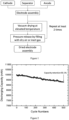
- FIG. 1 shows an embodiment of the method disclosed herein.
- An electrode assembly is made by stacking a plurality of anodes and a plurality of cathodes with separators interposed therebetween.
- the electrode assembly is dried in a drying chamber under vacuum at an elevated temperature.
- the drying chamber is then filled with hot, dry air. The steps of vacuum drying and pressure restoring are repeated until the desired water content is achieved.
- lithium-ion battery manufacturing processes are carried out in dry rooms where the environment must be carefully controlled to preserve optimum production conditions.
- the dew point of the air is an indicator of the quality of the dry room.
- Typical dew point values for battery production range from -40 °C to -65 °C.
- Efficiency and service life of a battery are determined in the cell production stage.
- An electrode assembly can be constructed by sequentially stacking at least one negative electrode, at least one separator, and at least one positive electrode.
- the number and arrangement of the at least one positive electrode, the at least one negative electrode, and the at least one separator, for configuring the electrode assembly are not particularly limited.
- the electrode assembly has a stacked structure in which two outermost electrodes comprise an opposing polarities (i.e., a positive electrode and a negative electrode), such as a positive electrode/separator/negative electrode structure or a positive electrode/separator/negative electrode/separator/positive electrode/separator/negative electrode structure.
- an electrode assembly for use in a nonaqueous electrolyte secondary battery. In certain embodiments, disclosed is an electrode assembly for use in a lithium-ion battery.
- the electrode assembly has a stacked structure in which two outermost electrodes comprise the same polarity (i.e., positive electrodes or negative electrodes), such as a positive electrode/separator/negative electrode/separator/positive electrode structure or a negative electrode/separator/positive electrode/separator/negative electrode structure.
- the electrode assembly has a structure in which a separator is disposed on one of the outermost sides, such as a separator/positive electrode/separator/negative electrode structure or a positive electrode/separator/negative electrode/separator structure. In other embodiments, the electrode assembly has a structure in which separators are disposed on both the outermost sides, such as a separator/positive electrode/separator/negative electrode/separator structure.
- the electrode assembly is assembled under strict humidity control in which the air has a dew point of -65 °C. In some embodiments, the electrode assembly is assembled under dry conditions in which the air has a dew point of - 50 °C, -40 °C, -30 °C, -20 °C, -10 °C, 0 °C, 5 °C, or 10 °C. In certain embodiments, the electrode assembly is assembled in the open air with no control of humidity.
- the assembling step for electrode assembly is not required to be carried out in a dry room.
- the electrode assembly can be assembled under a relative humidity from about 40% to about 100%, from about 40% to about 90%, from about 40% to about 80%, from about 50% to about 100%, from about from about 50% to about 90%, from about 50% to about 80%, from about 60% to about 100%, or from about 60% to about 90%.
- the electrode assembly can be assembled under a relative humidity of more than 40%, more than 50%, more than 60%, more than 70%, or more than 80%.
- the prepared electrode assembly will be dried immediately after the assembling step.
- One of the advantages of the present invention is that the prepared electrode assembly is not required for immediate use.
- the electrode assembly can be stored for at least 1 hour, 2 hours, 3 hours, 5 hours, 8 hours, 12 hours, 1 day, 2 days, 3 days, 4 days, 5 days, 6 days or 1 week in the open air at room temperature under atmospheric pressure before the high temperature drying step. In other embodiments, the electrode assembly can be stored for at least 1 hour, 2 hours, 3 hours, 5 hours, 8 hours, 12 hours, 1 day, 2 days, 3 days, 4 days, 5 days, 6 days or 1 week at an elevated temperature (such as 40-60 °C) under atmospheric pressure before the high temperature drying step.
- an elevated temperature such as 40-60 °C
- the prepared electrode can be stored at an elevated temperature (such as 40-60 °C) under atmospheric pressure for a relatively long time (such as 1-3 months) with uncontrolled humidity. Despite the relatively long storage time of the electrodes under uncontrolled humidity condition, the electrode assembly can still be dried to a desired low moisture content (such as below 20 ppm or even lower).
- the water content of the electrodes is measured.
- the water content of the electrodes are from about 100 ppm to about 1,000 ppm, from about 100 ppm to about 800 ppm, from about 100 ppm to about 600 ppm, from about 100 ppm to about 400 ppm, from about 100 ppm to about 200 ppm, or from about 200 ppm to about 600 ppm.
- the water content of electrodes are greater than 100 ppm, greater than 200 ppm, greater than 400 ppm, greater than 600 ppm, greater the 800 ppm, greater than 1,000 ppm, greater than 1,500 ppm, greater than 2,000 ppm, greater than 2,500 ppm or greater than 3,000 ppm.
- the separator disposed between the opposing active anode and cathode surfaces can prevent contact between the anode and cathode and a short circuit of the lithium-ion battery.
- the separator may comprise woven or nonwoven polymeric fibers, natural fibers, carbon fibers, glass fibers or ceramic fibers.
- the separator comprises woven or nonwoven polymeric fibers.
- the fibers of the nonwoven or woven are made of organic polymers, such as polyolefin, polyethylene (PE), high-density polyethylene, linear low-density polyethylene, low-density polyethylene, ultrahigh-molecular-weight polyethylene, polypropylene (PP), polypropylene/polyethylene co-polymer, polybutylene, polypentene, polyacetal, polyamide, polycarbonate, polyimide (PI), polyetherether ketone, polysulfones, polyphenylene oxide, polyphenylene sulfide, polyacrylonitrile, polyvinylidene fluoride, polyoxymethylene, polyvinyl pyrrolidone, polyester, polyethylene terephthalate (PET), polybutylene terephthalate, polyethylene naphthalene, polybutylene naphthalate, derivatives thereof, or a combination thereof.
- organic polymers such as polyolefin, polyethylene (PE), high-density polyethylene,
- the separator is made of polyolefinic fibers selected from the group consisting of polyethylene, high-density polyethylene, linear low-density polyethylene, low-density polyethylene, ultrahigh-molecular-weight polyethylene, polypropylene, polypropylene/polyethylene co-polymer, and combinations thereof.
- the separator is made of polymeric fibers selected from the group consisting of polyester, polyacetal, polyamide, polycarbonate, polyimide, polyetherether ketone, polyether sulfone, polyphenylene oxide, polyphenylene sulfide, polyethylene naphthalene, and combinations thereof.
- the polymeric fiber is not polyethylene, high-density polyethylene, linear low-density polyethylene, low-density polyethylene, ultrahigh-molecular-weight polyethylene, polypropylene, or polypropylene/polyethylene co-polymer.
- the polymeric fiber is not polyacetal, polyether sulfone, polyphenylene oxide, polyphenylene sulfide, or polycarbonate.
- polymeric fiber is not polyamide, polyimide, or polyetherether ketone. But all other known polymeric fibers or many natural fibers can be used as well.
- the separator disclosed herein has a melting point of 100 °C or higher, 110 °C or higher, 120 °C or higher, 130 °C or higher, 140 °C or higher, 150 °C or higher, 160 °C or higher, 170 °C or higher, 180 °C or higher, 190 °C or higher, 200 °C or higher, 210 °C or higher, 220 °C or higher, 230 °C or higher, 240 °C or higher, or 250 °C or higher.
- the separator has a melting point from about 100 °C to about 300 °C, from about 120 °C to about 300 °C, from about 100 °C to about 250 °C, from about 120 °C to about 250 °C, from about 140 °C to about 250 °C, from about 160 °C to about 250 °C, from about 180 °C to about 250 °C, or from about 200 °C to about 250 °C.
- the separator having high melting point shows high thermal stability and therefore can be dried at high temperature without thermally shrinking. This also allows the drying to be more efficiently performed. Therefore, the electrode assembly can be dried in a relatively short time, resulting in a short production time.
- the separator can be in a coated or uncoated form.
- the separator has a thickness from about 10 ⁇ m to about 200 ⁇ m, from about 30 ⁇ m to about 100 ⁇ m, from about 10 ⁇ m to about 75 ⁇ m, from about 10 ⁇ m to about 50 ⁇ m, from about 10 ⁇ m to about 20 ⁇ m, from about 15 ⁇ m to about 40 ⁇ m, from about 15 ⁇ m to about 35 ⁇ m, from about 20 ⁇ m to about 40 ⁇ m, from about 20 ⁇ m to about 35 ⁇ m, from about 20 ⁇ m to about 30 ⁇ m, from about 30 ⁇ m to about 60 ⁇ m, from about 30 ⁇ m to about 50 ⁇ m, or from about 30 ⁇ m to about 40 ⁇ m.
- the separator has a thickness of about 15 ⁇ m, about 20 ⁇ m, or about 25 ⁇ m. In some embodiments, the separator of the present invention has a thickness of less than 40 ⁇ m, less than 35 ⁇ m, less than 30 ⁇ m, less than 25 ⁇ m, or less than 20 ⁇ m. If the separator is sufficiently thin, the moisture may be evaporated at high drying rates.
- the electrode assembly is loosely stacked.
- the loosely stacked electrode assembly there is a void space between the electrode layer and separator layer, allowing moisture to escape. Therefore, the loosely stacked electrode assembly can be effectively dried in a short period of time.
- the tightly packed electrode assembly has little or no void space between the electrode layer and separator layer, thus reducing airflow and drying efficiency.
- the positive electrode, separator and negative electrode are stacked and spirally wound into a jelly-roll configuration before drying. Since a roll electrode assembly is tightly packed, there is also little or no void space between the electrode layer and separator layer, thus reducing airflow and drying efficiency. In some embodiments, the electrode assembly is not in a spirally-wound form.
- a positive electrode includes a cathode electrode layer supported on a cathode current collector.
- the cathode electrode layer comprises at least a cathode material and a binder material.
- the cathode electrode layer may further comprise a conductive agent for enhancing electron conductivity of the cathode electrode layer.
- a negative electrode includes an anode electrode layer supported on an anode current collector.
- the anode electrode layer comprises at least an anode material and a binder material.
- the anode electrode layer may further comprise a conductive agent for enhancing electron conductivity of the anode electrode layer.
- the at least one cathode comprises a cathode current collector and a cathode electrode layer comprising a cathode material, a binder material and a conductive agent
- the at least one anode comprises an anode current collector and an anode electrode layer comprising an anode material, a binder material and a conductive agent
- each of the cathode and anode electrode layers independently has a void volume of less than 40%, less than 37%, less than 35%, less than 33%, less than 30%, less than 25%, less than 20%, less than 18%, less than 15%, less than 13%, less than 10%, or less than 8%, based on the total volume of the cathode or anode electrode layer.
- the void volume of the electrode layer is between 8% and 40%, between 8% and 35%, between 8% and 30%, between 10% and 30%, between 13% and 30%, between 13% and 33%, between 15% and 30%, between 18% and 30%, between 20% and 30%, or between 25% and 30%, based on the total volume of the cathode or anode electrode layer.
- the void volume of the electrode layer is 35% or more, both the energy density and power output of the battery are low.
- the void volume of the electrode layer is between 10% and 35%, the battery exhibits good diffusibility of lithium ions and high-output performance.
- each of the cathode and anode current collectors which can be in the form of a foil, sheet or film, is independently stainless steel, titanium, nickel, aluminum, copper or electrically-conductive resin.
- the cathode current collector is an aluminum thin film.
- the anode current collector is a copper thin film. In certain embodiments, the current collector is not subjected to a surface treatment.
- the current collector has a thickness from about 6 ⁇ m to about 100 ⁇ m. Thickness of the current collector will affect the volume occupied by the current collector within a battery and the amount of the electrode material and hence the capacity in the battery.
- the thickness of each of the cathode and anode electrode layers on the current collector is independently from about 1 ⁇ m to about 300 ⁇ m, from about 10 ⁇ m to about 300 ⁇ m, from about 20 ⁇ m to about 100 ⁇ m, from about 1 ⁇ m to about 100 ⁇ m, from about 1 ⁇ m to about 50 ⁇ m, from about 1 ⁇ m to about 40 ⁇ m, from about 10 ⁇ m to about 40 ⁇ m, from about 10 ⁇ m to about 30 ⁇ m, or from about 10 ⁇ m to about 25 ⁇ m.
- the thickness of the electrode layer on the current collector is about 10 ⁇ m, about 15 ⁇ m, about 20 ⁇ m, about 25 ⁇ m, about 30 ⁇ m, about 35 ⁇ m, or about 40 ⁇ m.
- the density of each of the cathode and anode electrode layers on the current collector is independently from about 1.0 g/cm 3 to about 6.5 g/cm 3 , from about 1.0 g/cm 3 to about 5.0 g/cm 3 , from about 1.0 g/cm 3 to about 4.0 g/cm 3 , from about 1.0 g/cm 3 to about 3.5 g/cm 3 , from about 1.0 g/cm 3 to about 3.0 g/cm 3 , from about 1.0 g/cm 3 to about 2.0 g/cm 3 , from about 2.0 g/cm 3 to about 5.0 g/cm 3 , from about 2.0 g/cm 3 to about 4.0 g/cm 3 , from about 3.0 g/cm 3 to about 5.0 g/cm 3 , or from about 3.0 g/cm 3 to about 6.0 g/cm 3 .
- the cathode material is selected from the group consisting of LiCoO 2 (LCO), LiNiO 2 (LNO), LiNi x Mn y O 2 , Li 1+z Ni x Mn y Co 1-x-y O 2 , LiNi x Co y Al z O 2 , LiV 2 O 5 , LiTiS 2 , LiMoS 2 , LiMnO 2 , LiCrO 2 , LiMn 2 O 4 (LMO), LiFeO 2 , LiFePO 4 (LFP), LiNi 0.5 Mn 1.5 O 4 , LiNi 0.4 Mn 1.6 O 4 , and combinations thereof, wherein each x is independently from 0.3 to 0.8; each y is independently from 0.1 to 0.45; and each z is independently from 0 to 0.2.
- the cathode material is selected from the group consisting of LiCoO 2 , LiNiO 2 , LiNi x Mn y O 2 , Li 1+z Ni x Mn y Co 1-x-y O 2 , LiNi x Co y Al z O 2 , LiV 2 O 5 , LiTiS 2 , LiMoS 2 , LiMnO 2 , LiCrO 2 , LiMn 2 O 4 , LiFeO 2 , LiFePO 4 , LiNi 0.5 Mn 1.5 O 4 , LiNi 0.4 Mn 1.6 O 4 , and combinations thereof, wherein each x is independently from 0.4 to 0.6; each y is independently from 0.2 to 0.4; and each z is independently from 0 to 0.1.
- the cathode material is not LiCoO 2 , LiNiO 2 , LiV 2 O 5 , LiTiS 2 , LiMoS 2 , LiMnO 2 , LiCrO 2 , LiMn 2 O 4 , LiFeO 2 , LiFePO 4 , LiNi 0.5 Mn 1.5 O 4 , or LiNi 0.4 Mn 1.6 O 4 .
- the cathode material is not LiNi x Mn y O 2 , Li 1+z Ni x Mn y Co 1-x-y O 2 , or LiNi x Co y Al z O 2 , wherein each x is independently from 0.3 to 0.8; each y is independently from 0.1 to 0.45; and each z is independently from 0 to 0.2.
- the cathode active material is a nickel-containing cathode active material.
- the nickel-containing cathode active material is selected from the group consisting of Li 1+x NiO 2 , Li 1+x Ni a Mn b O 2 , Li 1+x Ni a Co c O 2 , Li 1+x Ni a Mn b Co c O 2 , Li 1+x Ni a Co c Al (1-a-c) O 2 , and combinations thereof, wherein 0 ⁇ x ⁇ 0.2, 0 ⁇ a ⁇ 1, 0 ⁇ b ⁇ 1, 0 ⁇ c ⁇ 1, and a+b+c ⁇ 1.
- the nickel-containing cathode active material is Li 1+x Ni a Mn b Co c O 2 , wherein 0 ⁇ x ⁇ 0.2, 0.3 ⁇ a ⁇ 0.8, 0.1 ⁇ b ⁇ 0.3 and 0.1 ⁇ c ⁇ 0.3.
- the nickel-containing cathode active material is selected from the group consisting of LiNi 0.33 Mn 0.33 Co 0.33 O 2 (NMC333), LiNi 0.4 Mn 0.4 Co 0.2 O 2 (NMC442), LiNi 0.5 Mn 0.3 Co 0.2 O 2 (NMC532), LiNi 0.6 Mn 0.2 Co 0.2 O 2 (NMC622), LiNi 0.7 Mn 0.15 Co 0.15 O 2 , LiNi 0.8 Mn 0.1 Co 0.1 O 2 (NMC811), Li 0.9 Mn 0.05 Co 0.05 O 2 , LiNi 0.92 Mn 0.04 Co 0.04 O 2 , LiNi 0.8 Co 0.15 Al 0.05 O 2 (NCA), LiNi 0.5 Mn 0.5 O 2 , LiNi 0.6 Mn 0.4 O 2 , LiNi 0.7 Mn 0.3 O 2 , LiNi 0.8 Mn 0.2 O 2 , LiNi 0.5 Co 0.5 O 2 , LiNi 0.6 Co 0.2 O 2
- the anode material is selected from the group consisting of natural graphite particulate, synthetic graphite particulate, Sn (tin) particulate, Li 4 Ti 5 O 12 particulate, Si (silicon) particulate, Si-C composite particulate, and combinations thereof. In other embodiments, the anode material is not natural graphite particulate, synthetic graphite particulate, Sn (tin) particulate, Li 4 Ti 5 O 12 particulate, Si (silicon) particulate, or Si-C composite particulate.
- the amount of each of the cathode and anode materials is independently at least 50%, at least 55%, at least 60%, at least 65%, at least 70%, at least 75%, at least 80%, at least 85%, at least 90%, or at least 95% by weight, based on the total weight of the cathode or anode electrode layer. In some embodiments, the amount of each of the cathode and anode materials is independently at most 50%, at most 55%, at most 60%, at most 65%, at most 70%, at most 75%, at most 80%, at most 85%, at most 90%, or at most 95% by weight, based on the total weight of the cathode or anode electrode layer.
- the conductive agent is selected from the group consisting of carbon, carbon black, graphite, expanded graphite, graphene, graphene nanoplatelets, carbon fibres, carbon nano-fibers, graphitized carbon flake, carbon tubes, carbon nanotubes, activated carbon, mesoporous carbon, and combinations thereof. In certain embodiments, the conductive agent is not carbon, carbon black, graphite, expanded graphite, graphene, graphene nanoplatelets, carbon fibres, carbon nano-fibers, graphitized carbon flake, carbon tubes, carbon nanotubes, activated carbon, or mesoporous carbon.
- the amount of the conductive agent in each of the cathode and anode electrode layers is independently at least 1%, at least 2%, at least 3%, at least 4%, at least 5%, at least 10%, at least 15%, at least 20%, at least 25%, at least 30%, at least 35%, at least 40%, at least 45%, or at least 50% by weight, based on the total weight of the cathode or anode electrode layer.
- the amount of the conductive agent in each of the cathode and anode electrode layers is independently at most 1%, at most 2%, at most 3%, at most 4%, at most 5%, at most 10%, at most 15%, at most 20%, at most 25%, at most 30%, at most 35%, at most 40%, at most 45%, or at most 50% by weight, based on the total weight of the cathode or anode electrode layer.
- the amount of the conductive agent in each of the cathode and anode electrode layers is independently from about 0.05 wt.% to about 0.5 wt.%, from about 0.1 wt.% to about 1 wt.%, from about 0.25 wt.% to about 2.5 wt.%, from about 0.5 wt.% to about 5 wt.%, from about 2 wt.% to about 5 wt.%, from about 3 wt.% to about 7 wt.%, or from about 5 wt.% to about 10 wt.%, based on the total weight of the cathode or anode electrode layer.
- An electrode slurry is prepared by dispersing an electrode active material, a binder material and a conductive agent in a solvent.
- the solvent is an aqueous solvent or organic solvent.
- the aqueous solvent is water.
- the organic solvent is N-methyl-2-pyrrolidone (NMP), dimethylformamide, dimethylacetamide, dimethyl sulfoxide or tetrahydrofuran.
- NMP N-methyl-2-pyrrolidone
- the solvent is not N-methyl-2-pyrrolidone, dimethylformamide, dimethylacetamide, dimethyl sulfoxide, or tetrahydrofuran.
- the solvent is not a mixture of N-methyl-2-pyrrolidone and water.
- the electrode slurry is coated onto the current collector to form a coated layer on the current collector.
- the coated current collector is then dried to prepare an electrode.
- the electrode slurry is dried at a temperature below 90 °C to prevent the slurry to be dried too quickly which may lead to cracking of the electrode layer.
- the coated layer is dried at a temperature from about 40 °C to about 90 °C, from about 40 °C to about 80 °C, from about 40 °C to about 70 °C, from about 40 °C to about 60 °C, from about 50 °C to about 90 °C, from about 50 °C to about 80 °C, or from about 50 °C to about 70 °C.
- the coated layer is dried at a temperature less than about 90 °C, less than about 80 °C, less than about 70 °C, less than about 60 °C, or less than about 50 °C. In some embodiments, the coated layer is dried at about 40 °C, about 50 °C, about 60 °C, about 70 °C, about 80 °C, or about 90 °C.
- the electrode assembly After assembling the electrode assembly, the electrode assembly is placed into a drying chamber.
- the drying chamber is connected to a vacuum pump, so that the pressure in the chamber can be reduced. The pressure is reduced sufficiently so as to lower the boiling point of water. The drying time can therefore be considerably reduced.
- the drying chamber is connected to a central vacuum supply, thereby allowing several vacuum drying ovens to be operated simultaneously. In some embodiments, the number of vacuum drying ovens connected to a central vacuum supply ranges from 1 to 20 depending on the number of pumps operated.
- a vacuum pump or central vacuum supply is connected to the drying chamber by a suction line equipped with a gas outlet valve.
- the drying chamber is also connected to a gas reservoir containing dry air or inert gas by a duct equipped with a gas inlet valve.
- a gas inlet valve When the gas outlet valve is closed and the gas inlet valve is opened, vacuum is lost in the drying chamber.
- the valve might be of a solenoid or needle type or a mass flow controller. Any devices allowing an appropriate flow adjustment might be used.
- a condenser can be provided between the drying chamber and the pump.
- the condenser condenses out water vapor, which is then separated.
- the electrode assembly can be dried under vacuum at a temperature from about 70 °C to about 155 °C, from about 80 °C to about 155 °C, from about 90 °C to about 155 °C, from about 100 °C to about 155 °C, from about 100 °C to about 140 °C, from about 100 °C to about 130 °C, from about 100 °C to about 120 °C, from about 100 °C to about 110 °C, or from about 110 °C to about 130 °C.
- the electrode assembly can be dried under vacuum at a temperature from about 80 °C to about 155 °C. In some embodiments, the electrode assembly can be dried under vacuum at a temperature of about 80 °C or higher, about 90 °C or higher, about 100 °C or higher, about 110 °C or higher, about 120 °C or higher, about 130 °C or higher, about 140 °C or higher, or about 150 °C or higher.
- the electrode assembly can be dried under vacuum at a temperature of less than 155 °C, less than 150 °C, less than 145 °C, less than 140 °C, less than 135 °C, less than 130 °C, less than 125 °C, less than 120 °C, less than 115 °C, less than 110 °C, less than 105 °C, less than 100 °C, or less than 90 °C.
- the time period for drying the electrode assembly under vacuum is from about 5 minutes to about 12 hours, from about 5 minutes to about 4 hours, from about 5 minutes to about 2 hours, from about 5 minutes to about 1 hour, from about 5 minutes to about 30 minutes, from about 5 minutes to about 15 minutes, from about 15 minutes to about 1 hour, from about 15 minutes to about 3 hours, from about 1 hour to about 10 hours, from about 1 hour to about 8 hours, from about 1 hour to about 6 hours, from about 1 hour to about 4 hours, from about 1 hour to about 2 hours, from about 2 hours to about 12 hours, from about 2 hours to about 8 hours, from about 2 hours to about 5 hours, from about 2 hours to about 3 hours, or from about 4 hours to about 12 hours.
- the time period for drying the electrode assembly under vacuum is from about 5 minutes to about 2 hours, or from about 15 minutes to about 30 minutes. In some embodiments, the time period for drying the electrode assembly under vacuum is at least 15 minutes, at least 30 minutes, at least 1 hour, at least 1.5 hours, at least 2 hours, at least 3 hours, at least 4 hours, or at least 5 hours. In certain embodiments, the time period for drying the electrode assembly under vacuum is less than 5 hours, less than 4 hours, less than 3 hours, less than 2 hours, less than 1.5 hours, less than 1 hour, or less than 30 minutes.
- any vacuum pumps that can reduce the pressure of the drying chamber can be used herein.
- Some non-limiting examples of the vacuum pumps include dry vacuum pumps, turbo pumps, rotary vane vacuum pumps, cryogenic pumps, and sorption pumps.
- the vacuum pump is an oil free pump.
- the oil free pump operates without the need for oil in the pump parts which are exposed to gases being pumped, or partial vacuum. Thus, any gases backstreaming through the pump are free from oil vapour. Progressive oil vapour deposited on surfaces of the electrode assembly may reduce the electrochemical performance of a battery.
- An example of such pump is a diaphragm vacuum pump.
- high vacuum can be achieved by using a two-stage pumping system to evacuate the drying chamber.
- the pumping system comprises a primary vacuum pump such as a rotary pump or diaphragm pump arranged in series with a high vacuum pump such as a turbo-molecular pump.
- the electrode assembly is dried under atmospheric pressure. In certain embodiments, the drying is performed in a vacuum state. In some embodiments, the vacuum state is maintained at a pressure within the range from about 1 ⁇ 10 -4 Pa to about 5 ⁇ 10 4 Pa, from about 1 ⁇ 10 -4 Pa to about 2.5 ⁇ 10 4 Pa, from about 1 ⁇ 10 -4 Pa to about 1 ⁇ 10 4 Pa, from about 1 ⁇ 10 -4 Pa to about 5 ⁇ 10 3 Pa, from about 1 ⁇ 10 -4 Pa to about 3 ⁇ 10 3 Pa, from about 1 ⁇ 10 -4 Pa to about 2 ⁇ 10 3 Pa, from about 1 ⁇ 10 -4 Pa to about 1 ⁇ 10 3 Pa, from about 1 ⁇ 10 3 Pa to about 5 ⁇ 10 4 Pa, from about 1 ⁇ 10 3 Pa to about 1 ⁇ 10 4 Pa, from about 1 ⁇ 10 3 Pa to about 5 ⁇ 10 3 Pa, from about 1 ⁇ 10 3 Pa to about 3 ⁇ 10 3 Pa, or from about 1 ⁇ 10 3 Pa to about 2 ⁇ 10 3 Pa.
- the vacuum state is maintained at a pressure less than about 5 ⁇ 10 4 Pa, less than about 2.5 ⁇ 10 4 Pa, less than about 1 ⁇ 10 4 Pa, less than about 5 ⁇ 10 3 Pa, less than about 3 ⁇ 10 3 Pa, less than about 2 ⁇ 10 3 Pa, or less than about 1 ⁇ 10 3 Pa. In some embodiments, the vacuum state is maintained at about 5 ⁇ 10 4 Pa, about 2.5 ⁇ 10 4 Pa, about 1 ⁇ 10 4 Pa, about 5 ⁇ 10 3 Pa, about 3 ⁇ 10 3 Pa, about 2 ⁇ 10 3 Pa, or about 1 ⁇ 10 3 Pa.
- the drying chamber vents directly to a gas reservoir containing dry air or inert gas via a gas inlet valve.
- Gas filling can enhance the removal of water vapour from the drying chamber, thereby increasing the removal efficiency of water from the electrode assembly and shorten the drying cycle.
- the gas reservoir is a nitrogen gas cylinder.
- the inert gas is selected from the group consisting of helium, argon, neon, krypton, xenon, nitrogen, carbon dioxide, and combinations thereof.
- the water content of the dry air or inert gas is maintained at a level of less than or equal to 10 ppm, less than or equal to 8 ppm, less than or equal to 5 ppm, less than or equal to 4 ppm, less than or equal to 3 ppm, less than or equal to 2 ppm, or less than or equal to 1 ppm.
- the dry air or inert gas is preheated before entering the drying chamber.
- the temperature of the dry air or inert gas is from about 70 °C to about 130 °C, from about 70 °C to about 110 °C, from about 70 °C to about 100 °C, from about 70 °C to about 90 °C, from about 70 °C to about 80 °C, from about 80 °C to about 155 °C, from about 80 °C to about 120 °C, from about 80 °C to about 100 °C, from about 90 °C to about 155 °C, from about 90 °C to about 130 °C, from about 90 °C to about 100 °C, from about 70 °C to about 155 °C, from about 100 °C to about 130 °C, or from about 100 °C to about 120 °C.
- the dry air or inert gas is preheated to a temperature from about 70 °C to about 155 °C before entering the drying chamber. In certain embodiments, the dry air or inert gas is preheated to at least 70 °C, at least 80 °C, at least 90 °C, at least 100 °C, at least 110 °C, or at least 120 °C.
- the dry air or inert gas stays in the drying chamber for a time period from about 30 seconds to about 2 hours, from about 1 minute to about 1 hour, from about 5 minutes to about 30 minutes, from about 5 minutes to about 15 minutes, from about 5 minutes to about 10 minutes, from about 10 minutes to about 30 minutes, from about 10 minutes to about 20 minutes, from about 10 minutes to about 15 minutes, from about 15 minutes to about 1 hour, from about 15 minutes to about 30 minutes, from about 15 minutes to about 20 minutes, or from about 30 minutes to about 1 hour.
- the dry air or inert gas stays in the drying chamber for a time period from about 30 seconds to about 2 hours, from about 5 minutes to about 2 hours, or from about 15 minutes to about 30 minutes.
- the dry air or inert gas stays in the drying chamber for at least 30 seconds, at least 1 minute, at least 5 minutes, at least 10 minutes, at least 15 minutes, at least 20 minutes, at least 25 minutes, at least 30 minutes, or at least 1 hour. In other embodiments, the dry air or inert gas stays in the drying chamber for less than 5 minutes, less than 10 minutes, less than 15 minutes, less than 20 minutes, less than 25 minutes, less than 30 minutes, or less than 1 hour.
- the electrode assembly can be further dried under vacuum after incubating the electrode assembly with the dry gas for a predetermined time.
- This procedure can be repeated as many times as required to reduce the moisture content of the electrode assembly to an appropriate level. In certain embodiments, this procedure can be repeated around 2 to 50 times until the moisture content in the electrode assembly is less than 50 ppm, less than 40 ppm, less than 30 ppm, less than 20 ppm, less than 19 ppm, less than 18 ppm, less than 17 ppm, less than 16 ppm, less than 15 ppm, less than 14 ppm, less than 13 ppm, less than 12 ppm, less than 11 ppm, less than 10 ppm, less than 9 ppm, less than 8 ppm, less than 7 ppm, less than 6 ppm, or less than 5 ppm by weight, based on the total weight of the dried electrode assembly.
- the steps of vacuum drying and gas filling can be repeated at least 2 times, at least 3 times, at least 4 times, at least 5 times, at least 6 times, at least 7 times, at least 8 times, at least 9 times, at least 10 times, at least 12 times, at least 14 times, at least 16 times, at least 18 times, at least 20 times, at least 22 times, at least 24 times, at least 26 times, at least 28 times, or at least 30 times.
- the steps of vacuum drying and gas filling can be repeated less than 30 times, less than 28 times, less than 26 times, less than 24 times, less than 22 times, less than 20 times, less than 18 times, less than 16 times, less than 14 times, less than 12 times, less than 10 times, less than 8 times, or less than 6 times.
- the steps of vacuum drying and gas filling can be repeated between 2 and 50 times, between 2 and 40 times, between 2 and 30 times, between 2 and 20 times, between 2 and 10 times, between 5 and 30 times, between 5 and 20 times, or between 5 and 10 times. In other embodiments, the steps of vacuum drying and gas filling can be repeated between 2 or more times.
- the process for drying the electrode assembly comprises vacuum drying, followed by hot air drying.
- the drying chamber blows hot air toward the electrode assembly from above and/or underneath.
- the hot air drying is performed at an air velocity from about 1 meter/second to about 50 meters/second, from about 1 meter/second to about 40 meters/second, from about 1 meter/second to about 30 meters/second, from about 1 meter/second to about 20 meters/second, from about 1 meter/second to about 10 meters/second, from about 10 meters/second to about 50 meters/second, from about 10 meters/second to about 40 meters/second, from about 10 meters/second to about 30 meters/second, from about 10 meters/second to about 20 meters/second, from about 20 meters/second to about 30 meters/second, from about 30 meters/second to about 40 meters/second, or from about 40 meters/second to about 50 meters/second.
- a heated inert gas i.e., helium, argon
- the drying gas might be preheated through heat exchange surfaces.
- the temperature of the hot air ranges from about 50 °C to about 155 °C, from about 60 °C to about 150 °C, from about 80 °C to about 150 °C, from about 100 °C to about 150 °C, from about 70 °C to about 150 °C, from about 70 °C to about 130 °C, from about 70 °C to about 100 °C, from about 80 °C to about 150 °C, from about 80 °C to about 130 °C, from about 80 °C to about 110 °C, from about 100 °C to about 140 °C, or from about 100 °C to about 120 °C.
- the temperature of the hot air is at least 70 °C, at least 80 °C, at least 90 °C, at least 100 °C, at least 110 °C, or at least 120 °C.
- the time period for hot air drying is from about 1 minute to about 2 hours, from about 1 minute to about 1 hour, from about 1 minute to about 30 minutes, from about 1 minute to about 15 minutes, from about 5 minutes to about 30 minutes, from about 5 minutes to about 20 minutes, from about 5 minute to about 15 minutes, from about 5 minutes to about 10 minutes, from about 10 minutes to about 1 hour, from about 10 minutes to about 30 minutes, from about 10 minutes to about 20 minutes, from about 15 minutes to about 1 hour, or from about 15 minutes to about 30 minutes.
- the electrode assembly can be further dried under vacuum after blowing hot air for a predetermined time. This procedure can be repeated as many times as required to reduce the moisture content of the electrode assembly to an appropriate level, such as 50 ppm, 40 ppm, 30 ppm, 20 ppm, 19 ppm, 18 ppm, 17 ppm, 16 ppm, 15 ppm, 14 ppm, 13 ppm, 12 ppm, 11 ppm, 10 ppm, 9 ppm, 8 ppm, 7 ppm, 6 ppm or 5 ppm.
- an appropriate level such as 50 ppm, 40 ppm, 30 ppm, 20 ppm, 19 ppm, 18 ppm, 17 ppm, 16 ppm, 15 ppm, 14 ppm, 13 ppm, 12 ppm, 11 ppm, 10 ppm, 9 ppm, 8 ppm, 7 ppm, 6 ppm or 5 ppm.
- the total processing time of steps 3-5 is from about 10 hours to about 40 hours, from about 10 hours to about 35 hours, from about 10 hours to about 30 hours, from about 10 hours to about 25 hours, from about 10 hours to about 20 hours, from about 10 hours to about 15 hours, from about 15 hours to about 30 hours, from about 15 hours to about 25 hours, from about 15 hours to about 20 hours, or from about 20 hours to about 30 hours. In some embodiments, the total processing time of steps 3-5 is less than about 40 hours, less than about 35 hours, less than about 30 hours, less than about 25 hours, less than about 20 hours, or less than about 15 hours. In certain embodiments, the total processing time of steps 3-5 is at least about 10 hours, at least about 15 hours, at least about 20 hours, at least about 25 hours, at least about 30 hours, or at least about 35 hours.
- an undried electrode assembly is immersed in an organic solvent. After a designated immersion period, the electrode assembly were removed from the organic solvent, placed into a vacuum drying chamber, and dried. The drying chamber can be backfilled with the inert gas and the drying step can be repeated.
- the organic solvent include chloroform, tetrachloromethane, benzene, acrylonitrile, ethyl carbonate, 1,2-dichloroethane, acetonitrile, diethyl ether and carbon disulphide. Immersing the electrode assembly in an organic solvent allows trapped water to be displaced by the bulk solvent. It is found that the electrode assembly can be efficiently dried.
- pore closure in separator is also observed due to dissolution of the polymer material in the organic solvent even under a short time period (such as a few seconds) of immersion of the electrode assembly.
- the rate of dissolution of the polymer is accelerated at a high drying temperature. This will decrease or even stop ionic flow between the anode and cathode and hence performance of a battery is significantly affected.
- the mechanical strength of the separator may also be affected due to solvent damage to the separator.
- the mechanical integrity of a battery separator is critical for prevention of internal short circuit. Therefore, the safety performance of the battery may also be affected.
- residual amounts of the organic solvent in the dried electrode assembly may also damage the separator.
- the electrode assembly can be dried to a water content of about 20 ppm or even lower without the assistance of any organic solvents.
- the dried electrode assembly is free of an organic solvent.
- the dried electrode assembly is free of chloroform, tetrachloromethane, benzene, acrylonitrile, ethyl carbonate, 1,2-dichloroethane, acetonitrile, diethyl ether, carbon disulphide, or a combination thereof.
- the dried electrode assembly comprises an organic solvent in an amount less than about 100 ppm, less than about 50 ppm, less than about 40 ppm, less than about 30 ppm, less than about 20 ppm, less than about 10 ppm, less than about 5 ppm, less than about 4 ppm, less than about 3 ppm, less than about 2 ppm, less than about 1 ppm, or less than about 0.5 ppm by weight, based on the total weight of the dried electrode assembly.
- the advantages of the present invention is that most of the fabrication can take place outside a dry room.
- the assembling process can take place outside a dry room or a glove box.
- only the step for filling electrolyte or both the steps for drying the electrode assembly and filing electrolyte are carried out in a dry room or a glove box.
- humidity control in the factory can be avoided, significantly lowering the investment cost.
- water content in the electrode assembly prepared by conventional methods contains an amount of water greater than 100 ppm by weight, based on the total weight of the electrode assembly. Even if the initial battery performance is acceptable, the rate of deterioration of the battery performance may be unacceptable. To be able to achieve sufficiently high battery performance, it would therefore be advantageous to have a low water content in the battery.
- the water content of the electrode assembly before drying is more than 100 ppm, more than 200 ppm, more than 300 ppm, more than 400 ppm, more than 500 ppm, more than 1,000 ppm, more than 2,000 ppm, more than 3,000 ppm, more than 4,000 ppm, more than 5,000 ppm, or more than 10,000 ppm by weight, based on the total weight of the electrode assembly before drying.
- the drying method can reduce the water content of the electrode assembly from a few thousand ppm to less than 20 ppm. In some embodiments, the drying method can reduce the water content of the electrode assembly from a few hundred ppm to less than 20 ppm.
- the electrode assembly prepared by the method disclosed herein has a particularly low water content, contributing to reliable performance of the lithium-ion batteries. In some embodiments, the water content of the dried electrode assembly is less than the water content of the undried electrode assembly.
- the water content in the dried electrode assembly is from about 5 ppm to about 50 ppm, from about 5 ppm to about 40 ppm, from about 5 ppm to about 30 ppm, from about 5 ppm to about 20 ppm, from about 5 ppm to about 15 ppm, from about 5 ppm to about 10 ppm, from about 3 ppm to about 30 ppm, from about 3 ppm to about 20 ppm, from about 3 ppm to about 15 ppm, or from about 3 ppm to about 10 ppm by weight, based on the total weight of the dried electrode assembly.
- the water content in the dried electrode assembly is less than 50 ppm, less than 40 ppm, less than 30 ppm, less than 20 ppm, less than 19 ppm, less than 18 ppm, less than 17 ppm, less than 16 ppm, less than 15 ppm, less than 14 ppm, less than 13 ppm, less than 12 ppm, less than 11 ppm, less than 10 ppm, less than 9 ppm, less than 8 ppm, less than 7 ppm, less than 6 ppm, less than 5 ppm, less than 4 ppm, less than 3 ppm, less than 2 ppm, or less than 1 ppm by weight, based on the total weight of the dried electrode assembly.
- the dried electrode assembly disclosed herein has a water concentration therein no greater than about 5 ppm by weight, based on the total weight of the dried electrode assembly.
- the undried electrode assembly comprises at least one undried anode and at least one undried cathode.
- each of the at least one undried anode and the at least one undried cathode has a water content of more than 5 ppm, more than 6 ppm, more than 7 ppm, more than 8 ppm, more than 9 ppm, more than 10 ppm, more than 11 ppm, more than 12 ppm, more than 13 ppm, more than 14 ppm, more than 15 ppm, more than 16 ppm, more than 17 ppm, more than 18 ppm, more than 19 ppm, more than 20 ppm, more than 30 ppm, more than 40 ppm, more than 50 ppm, more than 100 ppm, more than 200 ppm, more than 300 ppm, more than 400 ppm, more than 500 ppm, more than 1,000 ppm, more than 2,000 ppm, more than 3,000 ppm, more
- the dried electrode assembly comprises at least one dried anode and at least one dried cathode, wherein the at least one dried anode and at least one dried cathode have a water content of less than 50 ppm, less than 40 ppm, less than 30 ppm, less than 20 ppm, less than 19 ppm, less than 18 ppm, less than 17 ppm, less than 16 ppm, less than 15 ppm, less than 14 ppm, less than 13 ppm, less than 12 ppm, less than 11 ppm, less than 10 ppm, less than 9 ppm, less than 8 ppm, less than 7 ppm, less than 6 ppm, or less than 5 ppm by weight, based on the total weight of the at least one dried anode and at least one dried cathode.
- the undried electrode assembly comprises at least one undried separator.
- the at least one undried separator has a water content of more than 5 ppm, more than 6 ppm, more than 7 ppm, more than 8 ppm, more than 9 ppm, more than 10 ppm, more than 11 ppm, more than 12 ppm, more than 13 ppm, more than 14 ppm, more than 15 ppm, more than 16 ppm, more than 17 ppm, more than 18 ppm, more than 19 ppm, more than 20 ppm, more than 30 ppm, more than 40 ppm, more than 50 ppm, more than 100 ppm, more than 200 ppm, more than 300 ppm, more than 400 ppm, more than 500 ppm, more than 600 ppm, more than 700 ppm, more than 800 ppm, more than 900 ppm, more than 1,000 ppm, more than 1,500 ppm, more than 2,000 ppm, more than 1,500
- the water content of the at least one dried separator is less than the water content of the at least one undried separator.
- the dried electrode assembly comprises at least one dried separator, wherein the at least one dried separator has a water content of less than 50 ppm, less than 40 ppm, less than 30 ppm, less than 20 ppm, less than 19 ppm, less than 18 ppm, less than 17 ppm, less than 16 ppm, less than 15 ppm, less than 14 ppm, less than 13 ppm, less than 12 ppm, less than 11 ppm, less than 10 ppm, less than 9 ppm, less than 8 ppm, less than 7 ppm, less than 6 ppm, or less than 5 ppm by weight, based on the total weight of the at least one dried separator.
- the electrode assembly can then be naturally cooled to 50 °C or less before being removed from the drying chamber.
- the electrode assembly is cooled to 45 °C or less, 40 °C or less, 35 °C or less, 30 °C or less, or 25 °C or less before being removed from the drying chamber.
- the electrode assembly is cooled to room temperature.
- the electrode assembly is cooled down by blowing a dry gas or inert gas in order to reach the target temperature more quickly.
- each of the at least one anode and at least one cathode independently comprises a binder material selected from the group consisting of an organic-based binder material, a water-based binder material and a mixture of water-based and organic-based binder materials.
- each of the binder materials in the cathode and anode electrode layers is independently selected from the group consisting of styrene-butadiene rubber, acrylated styrene-butadiene rubber, acrylonitrile copolymer, acrylonitrile-butadiene rubber, nitrile butadiene rubber, acrylonitrile-styrene-butadiene copolymer, acryl rubber, butyl rubber, fluorine rubber, polytetrafluoroethylene, polyethylene, polypropylene, ethylene/propylene copolymers, polybutadiene, polyethylene oxide, chlorosulfonated polyethylene, polyvinylpyrrolidone, polyvinylpyridine, polyvinyl alcohol, polyvinyl acetate, polyepichlorohydrin, polyphosphazene, polyacrylonitrile, polystyrene, latex, acrylic resins, phenolic resins, epoxy resins, carboxy
- each of the binder materials in the cathode and anode electrode layers is independently selected from the group consisting of styrene-butadiene rubber, carboxymethyl cellulose, polyvinylidene fluoride, acrylonitrile copolymer, polyacrylic acid, polyacrylonitrile, poly(vinylidene fluoride)-hexafluoropropene, latex, a salt of alginic acid, and combinations thereof.
- each of the binder materials in the cathode and anode electrode layers is independently selected from SBR, CMC, PAA, a salt of alginic acid, or a combination thereof. In certain embodiments, each of the binder materials in the cathode and anode electrode layers is independently acrylonitrile copolymer. In some embodiments, each of the binder materials in the cathode and anode electrode layers is independently polyacrylonitrile.
- each of the binder materials in the cathode and anode electrode layers independently is free of styrene-butadiene rubber, carboxymethyl cellulose, polyvinylidene fluoride, acrylonitrile copolymer, polyacrylic acid, polyacrylonitrile, poly(vinylidene fluoride)-hexafluoropropene, latex, or a salt of alginic acid.
- the amount of the binder material in each of the cathode and anode electrode layers is independently at least 1%, at least 2%, at least 3%, at least 4%, at least 5%, at least 10%, at least 15%, at least 20%, at least 25%, at least 30%, at least 35%, at least 40%, at least 45%, or at least 50% by weight, based on the total weight of the cathode or anode electrode layer.
- the amount of the binder material in each of the cathode and anode electrode layers is independently at most 1%, at most 2%, at most 3%, at most 4%, at most 5%, at most 10%, at most 15%, at most 20%, at most 25%, at most 30%, at most 35%, at most 40%, at most 45%, or at most 50% by weight, based on the total weight of the cathode or anode electrode layer.
- the amount of the binder material in each of the cathode and anode electrode layers is independently is from about 2 wt.% to about 10 wt.%, from about 3 wt.% to about 6 wt.%, from about 5 wt.% to about 10 wt.%, from about 7.5 wt.% to about 15 wt.%, from about 10 wt.% to about 20 wt.%, from about 15 wt.% to about 25 wt.%, from about 20 wt.% to about 40 wt.%, or from about 35 wt.% to about 50 wt.%, based on the total weight of the cathode or anode electrode layer.
- the step of filling electrolyte is carried out in a dry room. After drying, the electrode assembly is placed inside a container and then an electrolyte is added to fill the pores of all of the layers of separator and electrodes, and each of the gaps between the positive and negative electrodes and the separator in the electrode assembly under an inert atmosphere before sealing.
- the method disclosed herein reduces the production costs of lithium-ion batteries by consuming less energy and shortens manufacturing times needed for drying. Therefore, this method is especially suited for industrial processes because of its low cost and ease of handling.
- an electrode assembly prepared by the method disclosed herein for a nonaqueous electrolyte secondary battery, comprising at least one anode, at least one cathode and at least one separator interposed between the at least one anode and at least one cathode, wherein the water content of the electrode assembly is less than 20 ppm by weight, based on the total weight of the electrode assembly.
- the water content of the electrode assembly is less than 20 ppm, less than 19 ppm, less than 18 ppm, less than 17 ppm, less than 16 ppm, less than 15 ppm, less than 14 ppm, less than 13 ppm, less than 12 ppm, less than 11 ppm, less than 10 ppm, less than 9 ppm, less than 8 ppm, less than 7 ppm, less than 6 ppm, or less than 5 ppm by weight, based on the total weight of the electrode assembly.
- the at least one cathode comprises a cathode current collector and a cathode electrode layer comprising a cathode material, a binder material and a conductive agent
- the at least one anode comprises an anode current collector and an anode electrode layer comprising an anode material, a binder material and a conductive agent
- each of the cathode and anode electrode layers independently has a void volume of less than 40%, less than 35%, less than 33%, less than 30%, less than 25%, less than 20%, or less than 15%, based on the total volume of the cathode or anode electrode layer.
- the lithium battery is able to retain at least about 80%, at least about 85 %, or at least 90 % of its initial storage capacity after 1,000 cycles at a rate of 1C at room temperature in a full cell. In some embodiments, the lithium battery is able to retain at least about 80 %, or at least about 85 % of its initial storage capacity after 1,500 cycles at a rate of 1C at room temperature in a full cell.
- a lithium battery comprising the electrode assembly prepared by the method disclosed herein.
- the water content in the electrode assembly was measured by Karl-fisher titration.
- the electrode assembly was cut into small pieces of 1 cm ⁇ 1 cm in a glove box filled with argon gas.
- the cut electrode assembly having a size of 1 cm ⁇ 1 cm was weighed in a sample vial.
- the weighed electrode assembly was then added into a titration vessel for Karl Fischer titration using Karl Fischer coulometry moisture analyzer (831 KF Coulometer, Metrohm, Switzerland). Measurement was repeated three times to find the average value.
- the water content in the electrodes or separator was measured by Karl-fisher titration.
- the electrode assembly was cut into small pieces of 1 cm ⁇ 1 cm in a glove box filled with argon gas.
- the electrode assembly was separated into the anode, cathode and separator layers.
- the water contents of the separated electrode layers and separator layers were analysed separately by Karl Fischer titration. Measurement was repeated three times to find the average value.
- a positive electrode slurry was prepared by mixing 94 wt.% cathode material (LNMC TLM 310, obtained from Xinxiang Tianli Energy Co. Ltd., China), 3 wt.% carbon black (SuperP; obtained from Timcal Ltd, Bodio, Switzerland) as a conductive agent, and 0.8 wt.% polyacrylic acid (PAA, #181285, obtained from Sigma-Aldrich, US), 1.5 wt.% styrene butadiene rubber (SBR, AL-2001, obtained from NIPPON A&L INC., Japan) and 0.7 wt.% polyvinylidene fluoride (PVDF; Solef ® 5130, obtained from Solvay S.A., Belgium) as a binder, which were dispersed in deionized water to form a slurry with a solid content of 50 wt.%.
- the slurry was homogenized by a planetary stirring mixer.
- the homogenized slurry was coated onto both sides of an aluminum foil having a thickness of 20 ⁇ m using a transfer coater (ZY-TSF6-6518, obtained from Jin Fan Zhanyu New Energy Technology Co. Ltd., China) with an area density of about 26 mg/cm 2 .
- the coated films on the aluminum foil were dried for 3 minutes by a 24-meter-long conveyor hot air drying oven as a sub-module of the transfer coater operated at a conveyor speed of about 8 meters/minute to obtain a positive electrode.
- the temperature-programmed oven allowed a controllable temperature gradient in which the temperature gradually rose from the inlet temperature of 60 °C to the outlet temperature of 75°C.
- a negative electrode slurry was prepared by mixing 90 wt.% hard carbon (HC; 99.5% purity, Ruifute Technology Ltd., Shenzhen, Guangdong, China), 5 wt.% carbon black and 5 wt.% polyacrylonitrile in deionized water to form a slurry having a solid content of 50 wt.%.
- the slurry was coated onto both sides of a copper foil having a thickness of 9 ⁇ m using a transfer coater with an area density of about 15 mg/cm 2 .
- the coated films on the copper foil were dried at about 50 °C for 2.4 minute by a 24-meter-long conveyor hot air dryer operated at a conveyor speed of about 10 meters/minute to obtain a negative electrode.
- Example 1 After drying, the resulting cathode film and anode film of Example 1 were used to prepare the cathode and anode respectively by cutting into individual electrode plates.
- An electrode assembly was prepared by stacking anodes, cathodes and separators interposed between the positive electrode and the negative electrode in the open air with no control of humidity.
- the separator was a microporous membrane (obtained from MITSUBISHI PAPER MILLS LTD, Japan) made of PET nonwoven fabric, which had a thickness of 30 ⁇ m.
- the electrode assembly was dried in a vacuum oven inside a glove box under a pressure of 5 ⁇ 10 3 Pa at 100 °C for 2 hours.
- the drying chamber was then filled with hot, dry air having a water content of 5 ppm and a temperature of 90 °C.
- the hot, dry air was retained in the drying chamber for 15 minutes before evacuating the drying chamber. This cycle was repeated 10 times.
- the average value of moisture content of the undried electrode assembly was 938 ppm.
- the average values of moisture contents of the dried electrode assembly, electrodes and separator were 9 ppm, 4 ppm and 5 ppm respectively.
- a pouch cell was assembled by packaging the dried electrode assembly in a case made of an aluminum-plastic laminated film.
- the cathode and anode electrode plates were kept apart by separators and the case was pre-formed.
- An electrolyte was then filled into the case holding the packed electrodes in high-purity argon atmosphere with moisture and oxygen content ⁇ 1 ppm.
- the electrolyte was a solution of LiPF 6 (1 M) in a mixture of ethylene carbonate (EC), ethyl methyl carbonate (EMC) and dimethyl carbonate (DMC) in a volume ratio of 1:1:1.
- EC ethylene carbonate
- EMC ethyl methyl carbonate
- DMC dimethyl carbonate
- the cell was tested galvanostatically at a current density of C/2 at 25 °C on a battery tester (BTS-5V20A, obtained from Neware Electronics Co. Ltd, China) between 3.0 V and 4.2 V.
- the nominal capacity was about 10 Ah.
- the cyclability performance of the pouch cell was tested by charging and discharging at a constant current rate of 1C between 3.0 V and 4.2 V. Test result of cyclability performance is shown in Figure 2 .
- a positive electrode slurry was were prepared by mixing 92 wt.% cathode material (LiMn 2 O 4 obtained from HuaGuan HengYuan LiTech Co. Ltd., Qingdao, China), 4 wt.% carbon black (SuperP; obtained from Timcal Ltd, Bodio, Switzerland) as a conductive agent, and 4 wt.% polyvinylidene fluoride (PVDF; Solef ® 5130, obtained from Solvay S.A., Belgium) as a binder, which were dispersed in N-methyl-2-pyrrolidone (NMP; purity of ⁇ 99%, Sigma-Aldrich, USA) to form a slurry with a solid content of 50 wt.%.
- the slurry was homogenized by a planetary stirring mixer.
- the homogenized slurry was coated onto both sides of an aluminum foil having a thickness of 20 ⁇ m using a transfer coater with an area density of about 40 mg/cm 2 .
- the coated films on the aluminum foil were dried for 6 minutes by a 24-meter-long conveyor hot air drying oven as a sub-module of the transfer coater operated at a conveyor speed of about 4 meters/minute to obtain a positive electrode.
- the temperature-programmed oven allowed a controllable temperature gradient in which the temperature gradually rose from the inlet temperature of 65 °C to the outlet temperature of 80 °C.
- a negative electrode slurry was prepared by mixing 90 wt.% of hard carbon (HC; purity of 99.5%, obtained from Ruifute Technology Ltd., Shenzhen, Guangdong, China) with 1.5 wt.% carboxymethyl cellulose (CMC, BSH-12, DKS Co. Ltd., Japan) and 3.5 wt.% SBR (AL-2001, NIPPON A&L INC., Japan) as a binder, and 5 wt.% carbon black as a conductive agent, which were dispersed in deionized water to form another slurry with a solid content of 50 wt.%.
- hard carbon HC
- CMC carboxymethyl cellulose
- SBR A&L INC., Japan
- the slurry was coated onto both sides of a copper foil having a thickness of 9 ⁇ m using a transfer coater with an area density of about 15 mg/cm 2 .
- the coated films on the copper foil were dried at about 50 °C for 2.4 minutes by a 24-meter-long conveyor hot air dryer operated at a conveyor speed of about 10 meters/minute to obtain a negative electrode.
- Example 3 After drying, the resulting cathode film and anode film of Example 3 were used to prepare the cathode and anode respectively by cutting into individual electrode plates.
- An electrode assembly was prepared by stacking anodes, cathodes and separators interposed between the positive electrode and the negative electrode in the open air with no control of humidity.
- the separator was a microporous membrane (Celgard, LLC, US) made of polyethylene having a thickness of 25 ⁇ m.
- the electrode assembly was dried in a vacuum oven inside a glove box under a pressure of 1 ⁇ 10 4 Pa at 92 °C for 3 hours.
- the drying chamber was then filled with hot, dry nitrogen having a water content of 5 ppm and a temperature of 85 °C. The hot, dry nitrogen was retained in the drying chamber for 5 minutes before evacuating the drying chamber. This cycle was repeated 5 times.
- a pouch cell containing the dried electrode assembly prepared by method described in Example 4 was assembled according to the method described in Example 2.
- the cell was tested galvanostatically at a current density of C/2 at 25 °C on a battery tester between 3.0 V and 4.2 V.
- the nominal capacity was about 8.5 Ah.
- the cyclability performance of the pouch cell was tested by charging and discharging at a constant current rate of 1C between 3.0 V and 4.2 V. Test result of cyclability performance is shown in Figure 3 .
- a positive electrode slurry was prepared by mixing 94 wt.% cathode material LiNi 0.33 Mn 0.33 Co 0.33 O 2 (obtained from Shenzhen Tianjiao Technology Co. Ltd., China), 3 wt.% carbon black (SuperP; obtained from Timcal Ltd, Bodio, Switzerland) as a conductive agent, and 1.5 wt.% polyacrylic acid (PAA, #181285, obtained from Sigma-Aldrich, US) and 1.5 wt.% polyacrylonitrile (LA 132, Chengdu Indigo Power Sources Co., Ltd., China) as a binder, which were dispersed in deionized water to form a slurry with a solid content of 50 wt.%.
- the slurry was homogenized by a planetary stirring mixer.
- the homogenized slurry was coated onto both sides of an aluminum foil having a thickness of 20 ⁇ m using a transfer coater with an area density of about 32 mg/cm 2 .
- the coated films on the aluminum foil were dried for 4 minutes by a 24-meter-long conveyor hot air drying oven as a sub-module of the transfer coater operated at a conveyor speed of about 6 meters/minute to obtain a positive electrode.
- the temperature-programmed oven allowed a controllable temperature gradient in which the temperature gradually rose from the inlet temperature of 60 °C to the outlet temperature of 75 °C.
- a negative electrode slurry was prepared by mixing 90 wt.% hard carbon, 5 wt.% carbon black and 5 wt.% polyacrylonitrile in deionized water to form a slurry having a solid content of 50 wt.%.
- the slurry was coated onto both sides of a copper foil having a thickness of 9 ⁇ m using a transfer coater with an area density of about 15 mg/cm 2 .
- the coated films on the copper foil were dried at about 50 °C for 2.4 minutes by a 24-meter-long conveyor hot air dryer operated at a conveyor speed of about 10 meters/minute to obtain a negative electrode.
- Example 5 After drying, the resulting cathode film and anode film of Example 5 were used to prepare the cathode and anode respectively by cutting into individual electrode plates.
- An electrode assembly was prepared by stacking anodes, cathodes and separators interposed between the positive electrode and the negative electrode in the open air with no control of humidity.
- the separator was a microporous membrane (Jiangxi Advanced Nanofiber Technology Co., Ltd., China) made of polyimide having a thickness of 20 ⁇ m.
- the electrode assembly was dried in a vacuum oven inside a glove box under a pressure of 1 ⁇ 10 3 Pa at 110 °C for 2 hours.
- the drying chamber was then filled with hot, dry air having a water content of 5 ppm and a temperature of 100 °C.
- the hot, dry air was retained in the drying chamber for 10 minutes before evacuating the drying chamber. This cycle was repeated 10 times.
- a pouch cell containing the dried electrode assembly prepared by method described in Example 6 was assembled according to the method described in Example 2.
- the cell was tested galvanostatically at a current density of C/2 at 25 °C on a battery tester between 3.0 V and 4.2 V.
- the nominal capacity was about 10 Ah.
- the cyclability performance of the pouch cell was tested by charging and discharging at a constant current rate of 1C between 3.0 V and 4.2 V. Test result of cyclability performance is shown in Figure 4 .
- a positive electrode slurry was prepared by mixing 91 wt.% cathode material LiFePO 4 (obtained from Xiamen Tungsten Co. Ltd., China), 5 wt.% carbon black (SuperP; obtained from Timcal Ltd, Bodio, Switzerland) as a conductive agent, and 4 wt.% polyacrylonitrile (LA 132, Chengdu Indigo Power Sources Co., Ltd., China) as a binder, which were dispersed in deionized water to form a slurry with a solid content of 50 wt.%.
- the slurry was homogenized by a planetary stirring mixer.
- the homogenized slurry was coated onto both sides of an aluminum foil having a thickness of 30 ⁇ m using a transfer coater with an area density of about 56 mg/cm 2 .
- the coated films on the aluminum foil were then dried for 6 minutes by a 24-meter-long conveyor hot air drying oven as a sub-module of the transfer coater operated at a conveyor speed of about 4 meters/minute to obtain a positive electrode.
- the temperature-programmed oven allowed a controllable temperature gradient in which the temperature gradually rose from the inlet temperature of 75 °C to the outlet temperature of 90 °C.
- a negative electrodes were prepared by mixing 90 wt.% of hard carbon (HC; purity of 99.5%, obtained from Ruifute Technology Ltd., China) with 1.5 wt.% CMC (BSH-12, DKS Co. Ltd., Japan) and 3.5 wt.% SBR (AL-2001, NIPPON A&L INC., Japan) as a binder, and 5 wt.% carbon black as a conductive agent, which were dispersed in deionized water to form another slurry with a solid content of 50 wt.%.
- the slurry was coated onto both sides of a copper foil having a thickness of 9 ⁇ m using a transfer coater with an area density of about 15 mg/cm 2 .
- the coated films on the copper foil were then dried at about 50 °C for 2.4 minutes by a 24-meter-long conveyor hot air dryer operated at a conveyor speed of about 10 meters/minute to obtain a negative electrode.
- Example 7 After drying, the resulting cathode film and anode film of Example 7 were used to prepare the cathode and anode respectively by cutting into individual electrode plates.
- An electrode assembly was prepared by stacking anodes, cathodes and separators interposed between the positive electrode and the negative electrode in the open air with no control of humidity.
- the separator was a ceramic coated microporous membrane (SEPARION, Evonik Industries, Germany) made of PET nonwoven fabric, which had a thickness of about 35 ⁇ m.
- the electrode assembly was dried in a vacuum oven inside a glove box under a pressure of 1 ⁇ 10 3 Pa at 120 °C for 4 hours.
- the drying chamber was then filled with hot, dry air having a water content of 5 ppm and a temperature of 110 °C.
- the hot, dry air was retained in the drying chamber for 5 minutes before evacuating the drying chamber. This cycle was repeated 7 times.
- a pouch cell containing the dried electrode assembly prepared by method described in Example 8 was assembled according to the method described in Example 2.
- the cell was tested galvanostatically at a current density of C/2 at 25 °C on a battery tester between 2.5 V and 3.6 V.
- the nominal capacity was about 4.6 Ah.
- the cyclability performance of the pouch cell was tested by charging and discharging at a constant current rate of 1C between 2.5 V and 3.6 V. Test result of cyclability performance is shown in Figure 5 .
- a positive electrode slurry was prepared by mixing 92 wt.% cathode material LiCoO 2 (obtained from Xiamen Tungsten Co. Ltd., China), 3 wt.% carbon black (SuperP; obtained from Timcal Ltd, Bodio, Switzerland) as a conductive agent, and 1 wt.% CMC (BSH-12, DKS Co.
- the homogenized slurry was coated onto both sides of an aluminum foil having a thickness of 20 ⁇ m using a transfer coater with an area density of about 32 mg/cm 2 .
- the coated films on the aluminum foil were dried for 4 minutes by a 24-meter-long conveyor hot air drying oven as a sub-module of the transfer coater operated at a conveyor speed of about 6 meters/minute to obtain a positive electrode.
- the temperature-programmed oven allowed a controllable temperature gradient in which the temperature gradually rose from the inlet temperature of 60 °C to the outlet temperature of 75 °C.
- a negative electrode slurry was prepared by mixing 90 wt.% hard carbon, 5 wt.% carbon black and 5 wt.% polyacrylonitrile in deionized water to form a slurry having a solid content of 50 wt.%.
- the slurry was coated onto both sides of a copper foil having a thickness of 9 ⁇ m using a transfer coater with an area density of about 15 mg/cm 2 .
- the coated films on the copper foil were dried at about 50 °C for 2.4 minutes by a 24-meter-long conveyor hot air dryer operated at a conveyor speed of about 10 meters/minute to obtain a negative electrode.
- Example 9 After drying, the resulting cathode film and anode film of Example 9 were used to prepare the cathode and anode respectively by cutting into individual electrode plates.
- An electrode assembly was prepared by stacking anodes, cathodes and separators interposed between the positive electrode and the negative electrode in the open air with no control of humidity. The electrode assembly was dried in a vacuum oven inside a glove box under a pressure of 5 ⁇ 10 4 Pa at 95 °C for 1.5 hours.
- the separator was a microporous membrane (Symmetrix, NEPTCO Corporation, US) made of PVDF and PET having a thickness of 30 ⁇ m.
- the drying chamber was then filled with hot, dry air having a water content of 5 ppm and a temperature of 90 °C. The hot, dry air was retained in the drying chamber for 30 minutes before evacuating the drying chamber. This cycle was repeated 10 times.
- a pouch cell containing the dried electrode assembly prepared by method described in Example 10 was assembled according to the method described in Example 2.
- the cell was tested galvanostatically at a current density of C/2 at 25 °C on a battery tester between 3.0 V and 4.2 V.
- the nominal capacity was about 10 Ah.
- the cyclability performance of the pouch cell was tested by charging and discharging at a constant current rate of 1C between 3.0 V and 4.2 V. Test result of cyclability performance is shown in Figure 6 .
- Positive and negative electrodes were prepared by the method described in Example 9.
- An electrode assembly was prepared by stacking anodes, cathodes and separators interposed between the positive electrode and the negative electrode in the open air with no control of humidity.
- the separator was a microporous membrane made of PVDF and PET (Symmetrix, NEPTCO Corporation, US) having a thickness of 30 ⁇ m.
- the electrode assembly was dried in a vacuum oven inside a glove box under a pressure of 3 ⁇ 10 3 Pa at 105 °C for 1.5 hours.
- the drying chamber was then filled with hot, dry air having a water content of 5 ppm and a temperature of 100 °C.
- the hot, dry air was retained in the drying chamber for 10 minutes before evacuating the drying chamber. This cycle was repeated 10 times.
- a pouch cell containing the dried electrode assembly prepared by method described in Example 11 was assembled according to the method described in Example 2.
- the cell was tested galvanostatically at a current density of C/2 at 25 °C on a battery tester between 3.0 V and 4.2 V.
- the nominal capacity was about 10 Ah.
- the cyclability performance of the pouch cell was tested by charging and discharging at a constant current rate of 1C between 3.0 V and 4.2 V. Test result of cyclability performance is shown in Figure 7 .
- Positive and negative electrodes were prepared by the method described in Example 5.
- An electrode assembly was prepared by stacking anodes, cathodes and separators interposed between the positive electrode and the negative electrode in the open air with no control of humidity.
- the electrode assembly was dried in a vacuum oven inside a glove box under a pressure of 2 ⁇ 10 3 Pa at 125 °C for 1 hour.
- the separator was a microporous membrane (Jiangxi Advanced Nanofiber Technology Co., Ltd., China) made of polyimide having a thickness of 20 ⁇ m.
- the drying chamber was then filled with hot, dry air having a water content of 5 ppm and a temperature of 120 °C. The hot, dry air was retained in the drying chamber for 15 minutes before evacuating the drying chamber. This cycle was repeated 10 times.
- a pouch cell containing the dried electrode assembly prepared by method described in Example 12 was assembled according to the method described in Example 2.
- the cell was tested galvanostatically at a current density of C/2 at 25 °C on a battery tester between 3.0 V and 4.2 V.
- the nominal capacity was about 10 Ah.
- the cyclability performance of the pouch cell was tested by charging and discharging at a constant current rate of 1C between 3.0 V and 4.2 V. Test result of cyclability performance is shown in Figure 8 .
- Positive and negative electrodes were prepared by the method described in Example 7.
- An electrode assembly was prepared by stacking anodes, cathodes and separators interposed between the positive electrode and the negative electrode in the open air with no control of humidity.
- the separator was a ceramic coated microporous membrane (SEPARION, Evonik Industries, Germany) made of PET nonwoven fabric, which had a thickness of about 35 ⁇ m.
- the electrode assembly was dried in a vacuum oven inside a glove box under a pressure of 1 ⁇ 10 4 Pa at 135 °C for 2 hours.
- the drying chamber was then filled with hot, dry air having a water content of 5 ppm and a temperature of 120 °C.
- the hot, dry air was retained in the drying chamber for 5 minutes before evacuating the drying chamber. This cycle was repeated 5 times.
- a pouch cell containing the dried electrode assembly prepared by method described in Example 13 was assembled according to the method described in Example 2.
- the cell was tested galvanostatically at a current density of C/2 at 25 °C on a battery tester between 2.5 V and 3.6 V.
- the nominal capacity was about 4.6 Ah.
- the cyclability performance of the pouch cell was tested by charging and discharging at a constant current rate of 1C between 2.5 V and 3.6 V. Test result of cyclability performance is shown in Figure 9 .
- Positive and negative electrodes were prepared by the method described in Example 5.
- An electrode assembly was prepared by stacking anodes, cathodes and separators interposed between the positive electrode and the negative electrode and spirally wound into a jelly-roll configuration in the open air with no control of humidity.
- the separator was a microporous membrane (obtained from MITSUBISHI PAPER MILLS LTD, Japan) made of PET nonwoven fabric, having a thickness of 30 ⁇ m.
- the electrode assembly was dried in a vacuum oven inside a glove box under a pressure of 660 Pa at 110 °C for 2 hours.
- the drying chamber was then filled with hot, dry air having a water content of 5 ppm and a temperature of 90 °C.
- the hot, dry air was retained in the drying chamber for 10 minutes before evacuating the drying chamber. This cycle was repeated 10 times.
- a pouch cell containing the dried electrode assembly prepared by method described in Example 14 was assembled according to the method described in Example 2.
- the cell was tested galvanostatically at a current density of C/2 at 25 °C on a battery tester between 3.0 V and 4.2 V.
- the nominal capacity was about 10 Ah.
- the cyclability performance of the pouch cell was tested by charging and discharging at a constant current rate of 1C between 3.0 V and 4.2 V.
- Positive and negative electrodes were prepared by the method described in Example 5.
- An electrode assembly was assembled and dried by the method described in Example 6 except that the electrode assembly was dried in a vacuum oven at 160 °C instead of 110 °C.
- a pouch cell containing the dried electrode assembly prepared by method described in Comparative Example 1 was assembled according to the method described in Example 2.
- the cell was tested galvanostatically at a current density of C/2 at 25 °C on a battery tester between 3.0 V and 4.2 V.
- the nominal capacity was about 10 Ah.
- the cyclability performance of the pouch cell was tested by charging and discharging at a constant current rate of 1C between 3.0 V and 4.2 V.
- Positive and negative electrodes were prepared by the method described in Example 5.
- An electrode assembly was assembled and dried by the method described in Example 6 except that the electrode assembly was dried in a vacuum oven at 75 °C instead of 110 °C.
- a pouch cell containing the dried electrode assembly prepared by method described in Comparative Example 2 was assembled according to the method described in Example 2.
- the cell was tested galvanostatically at a current density of C/2 at 25 °C on a battery tester between 3.0 V and 4.2 V.
- the nominal capacity was about 10 Ah.
- the cyclability performance of the pouch cell was tested by charging and discharging at a constant current rate of 1C between 3.0 V and 4.2 V.
- Positive and negative electrodes were prepared by the method described in Example 5.
- An electrode assembly was assembled and dried by the method described in Example 12 except that the electrode assembly was dried in a vacuum oven for 24 hours continuously without repeating filling and evacuating the chamber.
- a pouch cell containing the dried electrode assembly prepared by method described in Comparative Example 3 was assembled according to the method described in Example 2.
- the cell was tested galvanostatically at a current density of C/2 at 25 °C on a battery tester between 3.0 V and 4.2 V.
- the nominal capacity was about 10 Ah.
- the cyclability performance of the pouch cell was tested by charging and discharging at a constant current rate of 1C between 3.0 V and 4.2 V.
- Positive and negative electrodes were prepared by the method described in Example 1. An electrode assembly was assembled and dried by the method described in Example 2 except that the number of cycle of vacuum drying and gas filling is 3 instead of 10.
- a pouch cell containing the dried electrode assembly prepared by method described in Comparative Example 4 was assembled according to the method described in Example 2.
- the cell was tested galvanostatically at a current density of C/2 at 25 °C on a battery tester between 3.0 V and 4.2 V.
- the nominal capacity was about 10 Ah.
- the cyclability performance of the pouch cell was tested by charging and discharging at a constant current rate of 1C between 3.0 V and 4.2 V.
- Positive and negative electrodes were prepared by the method described in Example 5.
- An electrode assembly was prepared by stacking anodes, cathodes and separators interposed between the positive electrode and the negative electrode and spirally wound into a jelly-roll configuration in the open air with no control of humidity.
- the separator was a microporous membrane (obtained from MITSUBISHI PAPER MILLS LTD, Japan) made of PET nonwoven fabric, which had a thickness of 30 ⁇ m.
- the electrode assembly was dried in a vacuum oven inside a glove box under a pressure of 650 Pa at 80 °C for 1 hours.
- the drying chamber was then filled with hot, dry air having a water content of 5 ppm and a temperature of 90 °C.
- the hot, dry air was retained in the drying chamber for 5 minutes before evacuating the drying chamber. This cycle was repeated 5 times.
- a pouch cell containing the dried electrode assembly prepared by method described in Comparative Example 5 was assembled according to the method described in Example 2.
- the cell was tested galvanostatically at a current density of C/2 at 25 °C on a battery tester between 3.0 V and 4.2 V.
- the nominal capacity was about 10 Ah.
- the cyclability performance of the pouch cell was tested by charging and discharging at a constant current rate of 1C between 3.0 V and 4.2 V.
- the formulations of the pouch cell of each of these Examples and Comparative Examples are summarized in Table 1 below.
- the drying conditions of the electrode assembly of each of these Examples and Comparative Examples are shown in Table 2 below.
- the moisture contents of the electrode assembly, electrodes and separators, and capacity retentions of the cell of each of these Examples and Comparative Examples are shown in Table 3.
- the electrochemical tests of these Examples show the good electrochemical stability of the battery in a wide range of potential, as well as outstanding cycle performance.
Landscapes
- Engineering & Computer Science (AREA)
- Chemical & Material Sciences (AREA)
- General Engineering & Computer Science (AREA)
- Mechanical Engineering (AREA)
- Chemical Kinetics & Catalysis (AREA)
- Electrochemistry (AREA)
- General Chemical & Material Sciences (AREA)
- Manufacturing & Machinery (AREA)
- Life Sciences & Earth Sciences (AREA)
- Materials Engineering (AREA)
- Microbiology (AREA)
- Health & Medical Sciences (AREA)
- Molecular Biology (AREA)
- Battery Electrode And Active Subsutance (AREA)
- Secondary Cells (AREA)
- Ceramic Capacitors (AREA)
- Fixed Capacitors And Capacitor Manufacturing Machines (AREA)
- Drying Of Solid Materials (AREA)
- Cell Separators (AREA)
Description
- The present invention relates to the field of batteries. In particular, this invention relates to methods for drying electrode assemblies of lithium-ion batteries and electrode assemblies made by the methods disclosed herein.
- Lithium-ion batteries (LIBs) have attracted extensive attention in the past two decades for a wide range of applications in portable electronic devices such as cellular phones and laptop computers. Due to rapid market development of electric vehicles (EV) and grid energy storage, high-performance, low-cost LIBs are currently offering one of the most promising options for large-scale energy storage devices.
- Currently, electrodes are prepared by dispersing fine powders of an active battery electrode material, a conductive agent, and a binder material in an appropriate solvent. The dispersion can be coated onto a current collector such as a copper or aluminum metal foil, and then dried at an elevated temperature to remove the solvent. Sheets of the cathode and anode are subsequently stacked or rolled with the separator separating the cathode and anode to form a battery.
- The lithium-ion battery manufacturing process is sensitive to moisture. A battery with high water content leads to serious attenuation of electrochemical performance and affects stability of battery. Therefore, environmental humidity must be controlled strictly for the production process of LIBs. Most of the LIBs are produced in an environment with less than 1 percent humidity. However, significant cost is incurred because of the stringent moisture-free process. To address the moisture sensitive issue of electrode assembly, it is important to dry the electrode assembly prior to electrolyte filing so as to reduce the water content in the battery.
-
Chinese Patent No. 104142045 B describes a method of drying an electrode assembly of LIBs. The method comprises heating an electrode assembly under vacuum at a temperature of 30-100 °C; filling the oven with dry air or inert gas; repeating these two steps for 1-10 times. This method provides the electrode assembly with a water content between 430.5 ppm and 488.1 ppm. -
Chinese Patent Application No. 1 05115250 A describes a method of drying an electrode assembly of LIBs. The method comprises heating an electrode assembly under vacuum at a temperature of 85±5 °C; filling the oven with hot, dry nitrogen gas; repeating these two steps for 10-20 times. This method provides the electrode assembly with a water content of less than 200 ppm. -
Chinese Patent No. 102735023 B describes a method of drying an electrode assembly of LIBs. The method comprises heating an electrode assembly under vacuum at a temperature of 20-70 °C; filling the oven with dry air or nitrogen gas; repeating these two steps for 5-50 times. This method provides the electrode assembly with a water content between 110.1 ppm and 137.2 ppm. -
Chinese Patent No. 103344097 B describes a method of drying an electrode assembly of LIBs. The method comprises heating an electrode assembly under vacuum at a temperature of 75-85 °C; filling the oven with a non-oxidizing gas; heating the electrode assembly to 75-85 °C; vacuum drying the electrode assembly again. However, this method does not provide the water content of the dried electrode assembly for evaluating the drying process. -
CN 105865159 A andUS 2007/009803 A1 disclose different methods for drying an electrode assembly. - The water contents of the electrode assemblies as dried by the existing methods range from a hundred ppm to several hundreds ppm, which may affect the cycling stability and rate capability of LIBs. In view of the above, there is always a need to develop a method for drying electrode assemblies of LIBs to low water content.
- The aforementioned needs are met by various aspects and embodiments disclosed herein.
- In one aspect, provided herein is a method of drying an electrode assembly, comprising the steps of:
- 1) stacking at least one anode, at least one cathode, and at least one separator interposed between the at least one anode and at least one cathode to prepare an electrode assembly;
- 2) placing the electrode assembly in a drying chamber;
- 3) drying the electrode assembly under vacuum at a temperature from about 80 °C to about 155 °C;
- 4) filling the drying chamber with dry air or inert gas; and
- 5) repeating steps 3) and 4) to obtain a dried electrode assembly,
- In some embodiments, the electrode assembly is dried under vacuum for a time period from about 5 minutes to about 4 hours, or from about 30 minutes to about 2 hours.
- In certain embodiments, the pressure in the drying chamber in step 3) is reduced to less than atmospheric pressure, 25 kPa, 15 kPa, 10 kPa, or 5 kPa.
- In some embodiments, the dry air or inert gas restores the drying chamber to atmospheric pressure.
- In certain embodiments, the temperature of the dry air or inert gas is from about 70 °C to about 155 °C, or from about 80 °C to about 120 °C.
- In some embodiments, the dry air or inert gas stays in the drying chamber for a time period from about 5 minutes to about 2 hours, or from about 5 minutes to about 30 minutes.
- In certain embodiments, steps 3) and 4) are repeated between 2 and 50 times, between 2 and 30 times, or between 2 and 20 times.
- In some embodiments, the dried electrode assembly comprises at least one dried anode and at least one dried cathode, wherein the at least one dried anode and at least one dried cathode have a water content of less than 20 ppm, less than 15 ppm, less than 10 ppm, or less than 5 ppm by weight, based on the total weight of the at least one dried anode and at least one dried cathode.
- In certain embodiments, the dried electrode assembly comprises at least one dried separator, wherein the at least one dried separator has a water content of less than 20 ppm, less than 15 ppm, less than 10 ppm, or less than 5 ppm by weight, based on the total weight of the at least one dried separator.
- In some embodiments, the at least one separator is made of polymeric fibers selected from the group consisting of polyolefin, polyethylene, high-density polyethylene, linear low-density polyethylene, low-density polyethylene, ultrahigh-molecular-weight polyethylene, polypropylene, polypropylene/polyethylene co-polymer, polybutylene, polypentene, polyacetal, polyamide, polycarbonate, polyimide, polyetherether ketone, polysulfones, polyphenylene oxide, polyphenylene sulfide, polyacrylonitrile, polyvinylidene fluoride, polyoxymethylene, polyvinyl pyrrolidone, polyester, polyethylene terephthalate, polybutylene terephthalate, polyethylene naphthalene, polybutylene naphthalate, and combinations thereof.
- In certain embodiments, the melting point of the at least one separator is above 200 °C.
- In some embodiments, each of the at least one anode and at least one cathode independently comprises a binder material selected from the group consisting of styrene-butadiene rubber, acrylated styrene-butadiene rubber, acrylonitrile copolymer, acrylonitrile-butadiene rubber, nitrile butadiene rubber, acrylonitrile-styrene-butadiene copolymer, acryl rubber, butyl rubber, fluorine rubber, polytetrafluoroethylene, polyethylene, polypropylene, ethylene/propylene copolymers, polybutadiene, polyethylene oxide, chlorosulfonated polyethylene, polyvinylpyrrolidone, polyvinylpyridine, polyvinyl alcohol, polyvinyl acetate, polyepichlorohydrin, polyphosphazene, polyacrylonitrile, polystyrene, latex, acrylic resins, phenolic resins, epoxy resins, carboxymethyl cellulose, hydroxypropyl cellulose, cellulose acetate, cellulose acetate butyrate, cellulose acetate propionate, cyanoethylcellulose, cyanoethylsucrose, polyester, polyamide, polyether, polyimide, polycarboxylate, polycarboxylic acid, polyacrylic acid, polyacrylate, polymethacrylic acid, polymethacrylate, polyacrylamide, polyurethane, fluorinated polymer, chlorinated polymer, a salt of alginic acid, polyvinylidene fluoride, poly(vinylidene fluoride)-hexafluoropropene, and combinations thereof.
- In certain embodiments, the salt of alginic acid comprises a cation selected from Na, Li, K, Ca, NH4, Mg, Al, or a combination thereof.
- In another aspect, provided herein is a lithium battery comprising the electrode assembly prepared by the method disclosed herein.
-
-
Figure 1 depicts an embodiment of the method disclosed herein. -
Figure 2 depicts cycling performance of an electrochemical cell containing an electrode assembly prepared by the method described in Example 2. -
Figure 3 depicts cycling performance of an electrochemical cell containing an electrode assembly prepared by the method described in Example 4. -
Figure 4 depicts cycling performance of an electrochemical cell containing an electrode assembly prepared by the method described in Example 6. -
Figure 5 depicts cycling performance of an electrochemical cell containing an electrode assembly prepared by the method described in Example 8. -
Figure 6 depicts cycling performance of an electrochemical cell containing an electrode assembly prepared by the method described in Example 10. -
Figure 7 depicts cycling performance of an electrochemical cell containing an electrode assembly prepared by the method described in Example 11. -
Figure 8 depicts cycling performance of an electrochemical cell containing an electrode assembly prepared by the method described in Example 12. -
Figure 9 depicts cycling performance of an electrochemical cell containing an electrode assembly prepared by the method described in Example 13. - Provided herein is a method of drying an electrode assembly, comprising the steps of
- 1) stacking at least one anode, at least one cathode, and at least one separator interposed between the at least one anode and at least one cathode to prepare an electrode assembly;
- 2) placing the electrode assembly in a drying chamber;
- 3) drying the electrode assembly under vacuum at a temperature from about 80 °C to about 155 °C;
- 4) filling the drying chamber with dry air or inert gas; and
- 5) repeating steps 3) and 4) to obtain a dried electrode assembly,
- The term "electrode" refers to a "cathode" or an "anode."
- The term "positive electrode" is used interchangeably with cathode. Likewise, the term "negative electrode" is used interchangeably with anode.
- The term "binder material" refers to a chemical or a substance that can be used to hold the electrode material and conductive agent in place.
- The term "water-based binder material" refers to a water-soluble or water-dispersible binder polymer. Some non-limiting examples of the water-based binder material include styrene-butadiene rubber, acrylated styrene-butadiene rubber, acrylonitrile-butadiene rubber, acryl rubber, butyl rubber, fluorine rubber, polytetrafluoroethylene, polyethylene, polypropylene, ethylene/propylene copolymers, polybutadiene, polyethylene oxide, polyvinylpyrrolidone, polyepichlorohydrin, polyphosphazene, polyacrylonitrile, polystyrene, ethylene/propylene/diene copolymers, polyvinylpyridine, chlorosulfonated polyethylene, latex, polyester resins, acrylic resins, phenolic resins, epoxy resins, polyvinyl alcohol, carboxymethyl cellulose, hydroxypropyl cellulose, and combinations thereof.
- The term "organic-based binder material" refers to a binder dissolved or dispersed in an organic solvent, in particular, N-methyl-2-pyrrolidone (NMP). Some non-limiting examples of the organic-based binder material include polytetrafluoroethylene (PTFE), perfluoroalkoxy polymer (PFA), polyvinylidene fluoride (PVDF), copolymer of tetrafluoroethylene (TFE) and hexafluoropropylene (HFP), fluorinated ethylene-propylene (FEP) copolymer, and terpolymer of tetrafluoroethylene, hexafluoropropylene and vinylidene fluoride, and combinations thereof.
- The term "current collector" refers to a support for coating the electrode material and a chemically inactive high electron conductor for keeping an electric current flowing to electrodes during discharging or charging a secondary battery.
- The term "conductive agent" refers to a material which is chemically inactive and has good electrical conductivity. Therefore, the conductive agent is often mixed with an electrode active material at the time of forming an electrode to improve electrical conductivity of the electrode. In some embodiments, the conductive agent is a carbonaceous material.
- The term "electrode assembly" refers to a structure comprising at least one positive electrode, at least one negative electrode, and at least one separator interposed between the positive electrode and the negative electrode.
- The term "room temperature" refers to indoor temperatures from about 18 °C to about 30 °C, e.g., 18, 19, 20, 21, 22, 23, 24, 25, 26, 27, 28, 29, or 30 °C. In some embodiments, room temperature refers to a temperature of about 20 °C +/- 1 °C or +/- 2 °C or +/- 3 °C. In other embodiments, room temperature refers to a temperature of about 22 °C or about 25 °C.
- The term "water content" and "moisture content" are used interchangeably.
- The term "atmospheric pressure" refers to the pressure exerted by the weight of the atmosphere, which has a mean value of 101,325 Pa at sea level.
- The term "C rate" refers to the charging or discharging rate of a cell or battery, expressed in terms of its total storage capacity in Ah or mAh. For example, a rate of 1 C means utilization of all of the stored energy in one hour; a 0.1 C means utilization of 10% of the energy in one hour or full energy in 10 hours; and a 5 C means utilization of full energy in 12 minutes.
- The term "ampere-hour (Ah)" refers to a unit used in specifying the storage capacity of a battery. For example, a battery with 1 Ah capacity can supply a current of one ampere for one hour or 0.5 A for two hours, etc. Therefore, 1 Ampere-hour (Ah) is the equivalent of 3,600 coulombs of electrical charge. Similarly, the term "miniampere-hour (mAh)" also refers to a unit of the storage capacity of a battery and is 1/1,000 of an ampere-hour.
- The term "battery cycle life" refers to the number of complete charge/discharge cycles a battery can perform before its nominal capacity falls below 80% of its initial rated capacity.
- In the following description, all numbers disclosed herein are approximate values, regardless whether the word "about" or "approximate" is used in connection therewith. They may vary by 1 percent, 2 percent, 5 percent, or, sometimes, 10 to 20 percent. Whenever a numerical range with a lower limit, RL, and an upper limit, RU, is disclosed, any number falling within the range is specifically disclosed. In particular, the following numbers within the range are specifically disclosed: R=RL+k∗(RU-RL), wherein k is a variable ranging from 1 percent to 100 percent with a 1 percent increment, i.e., k is 1 percent, 2 percent, 3 percent, 4 percent, 5 percent,..., 50 percent, 51 percent, 52 percent,..., 95 percent, 96 percent, 97 percent, 98 percent, 99 percent, or 100 percent. Moreover, any numerical range defined by two R numbers as defined in the above is also specifically disclosed.
-
Figure 1 shows an embodiment of the method disclosed herein. An electrode assembly is made by stacking a plurality of anodes and a plurality of cathodes with separators interposed therebetween. The electrode assembly is dried in a drying chamber under vacuum at an elevated temperature. The drying chamber is then filled with hot, dry air. The steps of vacuum drying and pressure restoring are repeated until the desired water content is achieved. - Generally, lithium-ion battery manufacturing processes are carried out in dry rooms where the environment must be carefully controlled to preserve optimum production conditions. The dew point of the air is an indicator of the quality of the dry room. Typical dew point values for battery production range from -40 °C to -65 °C. Efficiency and service life of a battery are determined in the cell production stage.
- An electrode assembly can be constructed by sequentially stacking at least one negative electrode, at least one separator, and at least one positive electrode. The number and arrangement of the at least one positive electrode, the at least one negative electrode, and the at least one separator, for configuring the electrode assembly are not particularly limited. In some embodiments, the electrode assembly has a stacked structure in which two outermost electrodes comprise an opposing polarities (i.e., a positive electrode and a negative electrode), such as a positive electrode/separator/negative electrode structure or a positive electrode/separator/negative electrode/separator/positive electrode/separator/negative electrode structure.
- In some embodiments, disclosed is an electrode assembly for use in a nonaqueous electrolyte secondary battery. In certain embodiments, disclosed is an electrode assembly for use in a lithium-ion battery.
- In certain embodiments, the electrode assembly has a stacked structure in which two outermost electrodes comprise the same polarity (i.e., positive electrodes or negative electrodes), such as a positive electrode/separator/negative electrode/separator/positive electrode structure or a negative electrode/separator/positive electrode/separator/negative electrode structure.
- In some embodiments, the electrode assembly has a structure in which a separator is disposed on one of the outermost sides, such as a separator/positive electrode/separator/negative electrode structure or a positive electrode/separator/negative electrode/separator structure. In other embodiments, the electrode assembly has a structure in which separators are disposed on both the outermost sides, such as a separator/positive electrode/separator/negative electrode/separator structure.
- In certain embodiments, the electrode assembly is assembled under strict humidity control in which the air has a dew point of -65 °C. In some embodiments, the electrode assembly is assembled under dry conditions in which the air has a dew point of - 50 °C, -40 °C, -30 °C, -20 °C, -10 °C, 0 °C, 5 °C, or 10 °C. In certain embodiments, the electrode assembly is assembled in the open air with no control of humidity.
- In some embodiments, the assembling step for electrode assembly is not required to be carried out in a dry room. In some embodiments, the electrode assembly can be assembled under a relative humidity from about 40% to about 100%, from about 40% to about 90%, from about 40% to about 80%, from about 50% to about 100%, from about from about 50% to about 90%, from about 50% to about 80%, from about 60% to about 100%, or from about 60% to about 90%. In certain embodiments, the electrode assembly can be assembled under a relative humidity of more than 40%, more than 50%, more than 60%, more than 70%, or more than 80%. Generally, the prepared electrode assembly will be dried immediately after the assembling step. One of the advantages of the present invention is that the prepared electrode assembly is not required for immediate use. In some embodiments, the electrode assembly can be stored for at least 1 hour, 2 hours, 3 hours, 5 hours, 8 hours, 12 hours, 1 day, 2 days, 3 days, 4 days, 5 days, 6 days or 1 week in the open air at room temperature under atmospheric pressure before the high temperature drying step. In other embodiments, the electrode assembly can be stored for at least 1 hour, 2 hours, 3 hours, 5 hours, 8 hours, 12 hours, 1 day, 2 days, 3 days, 4 days, 5 days, 6 days or 1 week at an elevated temperature (such as 40-60 °C) under atmospheric pressure before the high temperature drying step.
- Another advantage of the present invention is that the prepared electrode can be stored at an elevated temperature (such as 40-60 °C) under atmospheric pressure for a relatively long time (such as 1-3 months) with uncontrolled humidity. Despite the relatively long storage time of the electrodes under uncontrolled humidity condition, the electrode assembly can still be dried to a desired low moisture content (such as below 20 ppm or even lower).
- Before assembling the electrode assembly, a pre-drying step for cathode and/or anode is not required. Before assembling the electrode assembly, the water content of the electrodes is measured. In some embodiments, the water content of the electrodes are from about 100 ppm to about 1,000 ppm, from about 100 ppm to about 800 ppm, from about 100 ppm to about 600 ppm, from about 100 ppm to about 400 ppm, from about 100 ppm to about 200 ppm, or from about 200 ppm to about 600 ppm. In certain embodiments, the water content of electrodes are greater than 100 ppm, greater than 200 ppm, greater than 400 ppm, greater than 600 ppm, greater the 800 ppm, greater than 1,000 ppm, greater than 1,500 ppm, greater than 2,000 ppm, greater than 2,500 ppm or greater than 3,000 ppm.
- The separator disposed between the opposing active anode and cathode surfaces can prevent contact between the anode and cathode and a short circuit of the lithium-ion battery. In some embodiments, the separator may comprise woven or nonwoven polymeric fibers, natural fibers, carbon fibers, glass fibers or ceramic fibers. In certain embodiments, the separator comprises woven or nonwoven polymeric fibers.
- In some embodiments, the fibers of the nonwoven or woven are made of organic polymers, such as polyolefin, polyethylene (PE), high-density polyethylene, linear low-density polyethylene, low-density polyethylene, ultrahigh-molecular-weight polyethylene, polypropylene (PP), polypropylene/polyethylene co-polymer, polybutylene, polypentene, polyacetal, polyamide, polycarbonate, polyimide (PI), polyetherether ketone, polysulfones, polyphenylene oxide, polyphenylene sulfide, polyacrylonitrile, polyvinylidene fluoride, polyoxymethylene, polyvinyl pyrrolidone, polyester, polyethylene terephthalate (PET), polybutylene terephthalate, polyethylene naphthalene, polybutylene naphthalate, derivatives thereof, or a combination thereof. In certain embodiments, the separator is made of polyolefinic fibers selected from the group consisting of polyethylene, high-density polyethylene, linear low-density polyethylene, low-density polyethylene, ultrahigh-molecular-weight polyethylene, polypropylene, polypropylene/polyethylene co-polymer, and combinations thereof. In some embodiments, the separator is made of polymeric fibers selected from the group consisting of polyester, polyacetal, polyamide, polycarbonate, polyimide, polyetherether ketone, polyether sulfone, polyphenylene oxide, polyphenylene sulfide, polyethylene naphthalene, and combinations thereof. In other embodiments, the polymeric fiber is not polyethylene, high-density polyethylene, linear low-density polyethylene, low-density polyethylene, ultrahigh-molecular-weight polyethylene, polypropylene, or polypropylene/polyethylene co-polymer. In further embodiments, the polymeric fiber is not polyacetal, polyether sulfone, polyphenylene oxide, polyphenylene sulfide, or polycarbonate. In still further embodiments, polymeric fiber is not polyamide, polyimide, or polyetherether ketone. But all other known polymeric fibers or many natural fibers can be used as well.
- In certain embodiments, the separator disclosed herein has a melting point of 100 °C or higher, 110 °C or higher, 120 °C or higher, 130 °C or higher, 140 °C or higher, 150 °C or higher, 160 °C or higher, 170 °C or higher, 180 °C or higher, 190 °C or higher, 200 °C or higher, 210 °C or higher, 220 °C or higher, 230 °C or higher, 240 °C or higher, or 250 °C or higher. In some embodiments, the separator has a melting point from about 100 °C to about 300 °C, from about 120 °C to about 300 °C, from about 100 °C to about 250 °C, from about 120 °C to about 250 °C, from about 140 °C to about 250 °C, from about 160 °C to about 250 °C, from about 180 °C to about 250 °C, or from about 200 °C to about 250 °C. The separator having high melting point shows high thermal stability and therefore can be dried at high temperature without thermally shrinking. This also allows the drying to be more efficiently performed. Therefore, the electrode assembly can be dried in a relatively short time, resulting in a short production time.
- The separator can be in a coated or uncoated form. In some embodiments, the separator has a thickness from about 10 µm to about 200 µm, from about 30 µm to about 100 µm, from about 10 µm to about 75 µm, from about 10 µm to about 50 µm, from about 10 µm to about 20 µm, from about 15 µm to about 40 µm, from about 15 µm to about 35 µm, from about 20 µm to about 40 µm, from about 20 µm to about 35 µm, from about 20 µm to about 30 µm, from about 30 µm to about 60 µm, from about 30 µm to about 50 µm, or from about 30 µm to about 40 µm.
- In certain embodiments, the separator has a thickness of about 15 µm, about 20 µm, or about 25 µm. In some embodiments, the separator of the present invention has a thickness of less than 40 µm, less than 35 µm, less than 30 µm, less than 25 µm, or less than 20 µm. If the separator is sufficiently thin, the moisture may be evaporated at high drying rates.
- In some embodiments, the electrode assembly is loosely stacked. In the loosely stacked electrode assembly, there is a void space between the electrode layer and separator layer, allowing moisture to escape. Therefore, the loosely stacked electrode assembly can be effectively dried in a short period of time. On the other hand, when the electrode assembly is pressed under pressure before drying, the tightly packed electrode assembly has little or no void space between the electrode layer and separator layer, thus reducing airflow and drying efficiency.
- In certain embodiments, the positive electrode, separator and negative electrode are stacked and spirally wound into a jelly-roll configuration before drying. Since a roll electrode assembly is tightly packed, there is also little or no void space between the electrode layer and separator layer, thus reducing airflow and drying efficiency. In some embodiments, the electrode assembly is not in a spirally-wound form.
- A positive electrode includes a cathode electrode layer supported on a cathode current collector. The cathode electrode layer comprises at least a cathode material and a binder material. The cathode electrode layer may further comprise a conductive agent for enhancing electron conductivity of the cathode electrode layer. A negative electrode includes an anode electrode layer supported on an anode current collector. The anode electrode layer comprises at least an anode material and a binder material. The anode electrode layer may further comprise a conductive agent for enhancing electron conductivity of the anode electrode layer.
- In some embodiments, the at least one cathode comprises a cathode current collector and a cathode electrode layer comprising a cathode material, a binder material and a conductive agent, and the at least one anode comprises an anode current collector and an anode electrode layer comprising an anode material, a binder material and a conductive agent, wherein each of the cathode and anode electrode layers independently has a void volume of less than 40%, less than 37%, less than 35%, less than 33%, less than 30%, less than 25%, less than 20%, less than 18%, less than 15%, less than 13%, less than 10%, or less than 8%, based on the total volume of the cathode or anode electrode layer. In certain embodiments, the void volume of the electrode layer is between 8% and 40%, between 8% and 35%, between 8% and 30%, between 10% and 30%, between 13% and 30%, between 13% and 33%, between 15% and 30%, between 18% and 30%, between 20% and 30%, or between 25% and 30%, based on the total volume of the cathode or anode electrode layer.
- If the void volume of the electrode layer is 35% or more, both the energy density and power output of the battery are low. When the void volume of the electrode layer is between 10% and 35%, the battery exhibits good diffusibility of lithium ions and high-output performance.
- The current collector acts to collect electrons generated by electrochemical reactions of the active battery electrode material or to supply electrons required for the electrochemical reactions. In some embodiments, each of the cathode and anode current collectors, which can be in the form of a foil, sheet or film, is independently stainless steel, titanium, nickel, aluminum, copper or electrically-conductive resin. In certain embodiments, the cathode current collector is an aluminum thin film. In some embodiments, the anode current collector is a copper thin film. In certain embodiments, the current collector is not subjected to a surface treatment.
- In some embodiments, the current collector has a thickness from about 6 µm to about 100 µm. Thickness of the current collector will affect the volume occupied by the current collector within a battery and the amount of the electrode material and hence the capacity in the battery.
- In certain embodiments, the thickness of each of the cathode and anode electrode layers on the current collector is independently from about 1 µm to about 300 µm, from about 10 µm to about 300 µm, from about 20 µm to about 100 µm, from about 1 µm to about 100 µm, from about 1 µm to about 50 µm, from about 1 µm to about 40 µm, from about 10 µm to about 40 µm, from about 10 µm to about 30 µm, or from about 10 µm to about 25 µm. In some embodiments, the thickness of the electrode layer on the current collector is about 10 µm, about 15 µm, about 20 µm, about 25 µm, about 30 µm, about 35 µm, or about 40 µm.
- In some embodiments, the density of each of the cathode and anode electrode layers on the current collector is independently from about 1.0 g/cm3 to about 6.5 g/cm3, from about 1.0 g/cm3 to about 5.0 g/cm3, from about 1.0 g/cm3 to about 4.0 g/cm3, from about 1.0 g/cm3 to about 3.5 g/cm3, from about 1.0 g/cm3 to about 3.0 g/cm3, from about 1.0 g/cm3 to about 2.0 g/cm3, from about 2.0 g/cm3 to about 5.0 g/cm3, from about 2.0 g/cm3 to about 4.0 g/cm3, from about 3.0 g/cm3 to about 5.0 g/cm3, or from about 3.0 g/cm3 to about 6.0 g/cm3. Similarly, an increase in the density of the electrode layer will result in a reduction of void volume in the final electrode coating and a denser electrode, thereby achieving desired battery capacity.
- In certain embodiments, the cathode material is selected from the group consisting of LiCoO2 (LCO), LiNiO2 (LNO), LiNixMnyO2, Li1+zNixMnyCo1-x-yO2, LiNixCoyAlzO2, LiV2O5, LiTiS2, LiMoS2, LiMnO2, LiCrO2, LiMn2O4 (LMO), LiFeO2, LiFePO4 (LFP), LiNi0.5Mn1.5O4, LiNi0.4Mn1.6O4, and combinations thereof, wherein each x is independently from 0.3 to 0.8; each y is independently from 0.1 to 0.45; and each z is independently from 0 to 0.2. In certain embodiments, the cathode material is selected from the group consisting of LiCoO2, LiNiO2, LiNixMnyO2, Li1+zNixMnyCo1-x-yO2, LiNixCoyAlzO2, LiV2O5, LiTiS2, LiMoS2, LiMnO2, LiCrO2, LiMn2O4, LiFeO2, LiFePO4, LiNi0.5Mn1.5O4, LiNi0.4Mn1.6O4, and combinations thereof, wherein each x is independently from 0.4 to 0.6; each y is independently from 0.2 to 0.4; and each z is independently from 0 to 0.1. In other embodiments, the cathode material is not LiCoO2, LiNiO2, LiV2O5, LiTiS2, LiMoS2, LiMnO2, LiCrO2, LiMn2O4, LiFeO2, LiFePO4, LiNi0.5Mn1.5O4, or LiNi0.4Mn1.6O4. In further embodiments, the cathode material is not LiNixMnyO2, Li1+zNixMnyCo1-x-yO2, or LiNixCoyAlzO2, wherein each x is independently from 0.3 to 0.8; each y is independently from 0.1 to 0.45; and each z is independently from 0 to 0.2.
- In certain embodiments, the cathode active material is a nickel-containing cathode active material. In some embodiments, the nickel-containing cathode active material is selected from the group consisting of Li1+xNiO2, Li1+xNiaMnbO2, Li1+xNiaCocO2, Li1+xNiaMnbCocO2, Li1+xNiaCocAl(1-a-c)O2, and combinations thereof, wherein 0≤x≤0.2, 0≤a≤1, 0≤b≤1, 0≤c≤1, and a+b+c≤1. In certain embodiments, the nickel-containing cathode active material is Li1+xNiaMnbCocO2, wherein 0≤x≤0.2, 0.3≤a≤0.8, 0.1≤b≤0.3 and 0.1≤c≤0.3. In certain embodiments, the nickel-containing cathode active material is selected from the group consisting of LiNi0.33Mn0.33Co0.33O2 (NMC333), LiNi0.4Mn0.4Co0.2O2 (NMC442), LiNi0.5Mn0.3Co0.2O2 (NMC532), LiNi0.6Mn0.2Co0.2O2 (NMC622), LiNi0.7Mn0.15Co0.15O2, LiNi0.8Mn0.1Co0.1O2 (NMC811), Li0.9Mn0.05Co0.05O2, LiNi0.92Mn0.04Co0.04O2, LiNi0.8Co0.15Al0.05O2 (NCA), LiNi0.5Mn0.5O2, LiNi0.6Mn0.4O2, LiNi0.7Mn0.3O2, LiNi0.8Mn0.2O2, LiNi0.5Co0.5O2, LiNi0.6Co0.4O2, LiNi0.7Co0.3O2, LiNi0.8Co0.2O2, LiNiO2, and combinations thereof. The nickel-containing composite oxide is relatively unstable in a moisture-containing environment. Therefore, performance of the cathode comprising the nickel-rich cathode active material is strongly affected by the residual moisture content in a battery.
- In some embodiments, the anode material is selected from the group consisting of natural graphite particulate, synthetic graphite particulate, Sn (tin) particulate, Li4Ti5O12 particulate, Si (silicon) particulate, Si-C composite particulate, and combinations thereof. In other embodiments, the anode material is not natural graphite particulate, synthetic graphite particulate, Sn (tin) particulate, Li4Ti5O12 particulate, Si (silicon) particulate, or Si-C composite particulate.
- In certain embodiments, the amount of each of the cathode and anode materials is independently at least 50%, at least 55%, at least 60%, at least 65%, at least 70%, at least 75%, at least 80%, at least 85%, at least 90%, or at least 95% by weight, based on the total weight of the cathode or anode electrode layer. In some embodiments, the amount of each of the cathode and anode materials is independently at most 50%, at most 55%, at most 60%, at most 65%, at most 70%, at most 75%, at most 80%, at most 85%, at most 90%, or at most 95% by weight, based on the total weight of the cathode or anode electrode layer.
- In some embodiments, the conductive agent is selected from the group consisting of carbon, carbon black, graphite, expanded graphite, graphene, graphene nanoplatelets, carbon fibres, carbon nano-fibers, graphitized carbon flake, carbon tubes, carbon nanotubes, activated carbon, mesoporous carbon, and combinations thereof. In certain embodiments, the conductive agent is not carbon, carbon black, graphite, expanded graphite, graphene, graphene nanoplatelets, carbon fibres, carbon nano-fibers, graphitized carbon flake, carbon tubes, carbon nanotubes, activated carbon, or mesoporous carbon.
- In certain embodiments, the amount of the conductive agent in each of the cathode and anode electrode layers is independently at least 1%, at least 2%, at least 3%, at least 4%, at least 5%, at least 10%, at least 15%, at least 20%, at least 25%, at least 30%, at least 35%, at least 40%, at least 45%, or at least 50% by weight, based on the total weight of the cathode or anode electrode layer. In some embodiments, the amount of the conductive agent in each of the cathode and anode electrode layers is independently at most 1%, at most 2%, at most 3%, at most 4%, at most 5%, at most 10%, at most 15%, at most 20%, at most 25%, at most 30%, at most 35%, at most 40%, at most 45%, or at most 50% by weight, based on the total weight of the cathode or anode electrode layer.
- In some embodiments, the amount of the conductive agent in each of the cathode and anode electrode layers is independently from about 0.05 wt.% to about 0.5 wt.%, from about 0.1 wt.% to about 1 wt.%, from about 0.25 wt.% to about 2.5 wt.%, from about 0.5 wt.% to about 5 wt.%, from about 2 wt.% to about 5 wt.%, from about 3 wt.% to about 7 wt.%, or from about 5 wt.% to about 10 wt.%, based on the total weight of the cathode or anode electrode layer.
- An electrode slurry is prepared by dispersing an electrode active material, a binder material and a conductive agent in a solvent. In some embodiments, the solvent is an aqueous solvent or organic solvent. In certain embodiments, the aqueous solvent is water. In some embodiments, the organic solvent is N-methyl-2-pyrrolidone (NMP), dimethylformamide, dimethylacetamide, dimethyl sulfoxide or tetrahydrofuran. In certain embodiments, the solvent is not N-methyl-2-pyrrolidone, dimethylformamide, dimethylacetamide, dimethyl sulfoxide, or tetrahydrofuran. In some embodiments, the solvent is not a mixture of N-methyl-2-pyrrolidone and water.
- The electrode slurry is coated onto the current collector to form a coated layer on the current collector. The coated current collector is then dried to prepare an electrode. The electrode slurry is dried at a temperature below 90 °C to prevent the slurry to be dried too quickly which may lead to cracking of the electrode layer. In some embodiments, the coated layer is dried at a temperature from about 40 °C to about 90 °C, from about 40 °C to about 80 °C, from about 40 °C to about 70 °C, from about 40 °C to about 60 °C, from about 50 °C to about 90 °C, from about 50 °C to about 80 °C, or from about 50 °C to about 70 °C. In certain embodiments, the coated layer is dried at a temperature less than about 90 °C, less than about 80 °C, less than about 70 °C, less than about 60 °C, or less than about 50 °C. In some embodiments, the coated layer is dried at about 40 °C, about 50 °C, about 60 °C, about 70 °C, about 80 °C, or about 90 °C.
- After assembling the electrode assembly, the electrode assembly is placed into a drying chamber. In some embodiments, the drying chamber is connected to a vacuum pump, so that the pressure in the chamber can be reduced. The pressure is reduced sufficiently so as to lower the boiling point of water. The drying time can therefore be considerably reduced. In certain embodiments, the drying chamber is connected to a central vacuum supply, thereby allowing several vacuum drying ovens to be operated simultaneously. In some embodiments, the number of vacuum drying ovens connected to a central vacuum supply ranges from 1 to 20 depending on the number of pumps operated. In certain embodiments, a vacuum pump or central vacuum supply is connected to the drying chamber by a suction line equipped with a gas outlet valve. In some embodiments, the drying chamber is also connected to a gas reservoir containing dry air or inert gas by a duct equipped with a gas inlet valve. When the gas outlet valve is closed and the gas inlet valve is opened, vacuum is lost in the drying chamber. The valve might be of a solenoid or needle type or a mass flow controller. Any devices allowing an appropriate flow adjustment might be used.
- To reduce the power required for the pumps, a condenser can be provided between the drying chamber and the pump. The condenser condenses out water vapor, which is then separated.
- Drying at low temperature cannot efficiently remove water from the electrode assembly. However, electrode layer will become embrittled and easily cracked when subjected to high drying temperatures. In certain embodiments, the electrode assembly can be dried under vacuum at a temperature from about 70 °C to about 155 °C, from about 80 °C to about 155 °C, from about 90 °C to about 155 °C, from about 100 °C to about 155 °C, from about 100 °C to about 140 °C, from about 100 °C to about 130 °C, from about 100 °C to about 120 °C, from about 100 °C to about 110 °C, or from about 110 °C to about 130 °C. In certain embodiments, the electrode assembly can be dried under vacuum at a temperature from about 80 °C to about 155 °C. In some embodiments, the electrode assembly can be dried under vacuum at a temperature of about 80 °C or higher, about 90 °C or higher, about 100 °C or higher, about 110 °C or higher, about 120 °C or higher, about 130 °C or higher, about 140 °C or higher, or about 150 °C or higher. In certain embodiments, the electrode assembly can be dried under vacuum at a temperature of less than 155 °C, less than 150 °C, less than 145 °C, less than 140 °C, less than 135 °C, less than 130 °C, less than 125 °C, less than 120 °C, less than 115 °C, less than 110 °C, less than 105 °C, less than 100 °C, or less than 90 °C.
- In some embodiments, the time period for drying the electrode assembly under vacuum is from about 5 minutes to about 12 hours, from about 5 minutes to about 4 hours, from about 5 minutes to about 2 hours, from about 5 minutes to about 1 hour, from about 5 minutes to about 30 minutes, from about 5 minutes to about 15 minutes, from about 15 minutes to about 1 hour, from about 15 minutes to about 3 hours, from about 1 hour to about 10 hours, from about 1 hour to about 8 hours, from about 1 hour to about 6 hours, from about 1 hour to about 4 hours, from about 1 hour to about 2 hours, from about 2 hours to about 12 hours, from about 2 hours to about 8 hours, from about 2 hours to about 5 hours, from about 2 hours to about 3 hours, or from about 4 hours to about 12 hours. In certain embodiments, the time period for drying the electrode assembly under vacuum is from about 5 minutes to about 2 hours, or from about 15 minutes to about 30 minutes. In some embodiments, the time period for drying the electrode assembly under vacuum is at least 15 minutes, at least 30 minutes, at least 1 hour, at least 1.5 hours, at least 2 hours, at least 3 hours, at least 4 hours, or at least 5 hours. In certain embodiments, the time period for drying the electrode assembly under vacuum is less than 5 hours, less than 4 hours, less than 3 hours, less than 2 hours, less than 1.5 hours, less than 1 hour, or less than 30 minutes.
- Any vacuum pumps that can reduce the pressure of the drying chamber can be used herein. Some non-limiting examples of the vacuum pumps include dry vacuum pumps, turbo pumps, rotary vane vacuum pumps, cryogenic pumps, and sorption pumps.
- In some embodiments, the vacuum pump is an oil free pump. The oil free pump operates without the need for oil in the pump parts which are exposed to gases being pumped, or partial vacuum. Thus, any gases backstreaming through the pump are free from oil vapour. Progressive oil vapour deposited on surfaces of the electrode assembly may reduce the electrochemical performance of a battery. An example of such pump is a diaphragm vacuum pump.
- In certain embodiments, high vacuum can be achieved by using a two-stage pumping system to evacuate the drying chamber. The pumping system comprises a primary vacuum pump such as a rotary pump or diaphragm pump arranged in series with a high vacuum pump such as a turbo-molecular pump.
- In some embodiments, the electrode assembly is dried under atmospheric pressure. In certain embodiments, the drying is performed in a vacuum state. In some embodiments, the vacuum state is maintained at a pressure within the range from about 1×10⁻⁴ Pa to about 5×10⁴ Pa, from about 1 ×10⁻⁴ Pa to about 2.5×10⁴ Pa, from about 1×10⁻⁴ Pa to about 1×10⁴ Pa, from about 1×10⁻⁴ Pa to about 5×10³ Pa, from about 1×10⁻⁴ Pa to about 3×10³ Pa, from about 1×10⁻⁴ Pa to about 2×10³ Pa, from about 1 ×10⁻⁴ Pa to about 1×10³ Pa, from about 1 ×10³ Pa to about 5×10⁴ Pa, from about 1×10³ Pa to about 1 ×10⁴ Pa, from about 1×10³ Pa to about 5×10³ Pa, from about 1 ×10³ Pa to about 3×10³ Pa, or from about 1×10³ Pa to about 2×10³ Pa. In certain embodiments, the vacuum state is maintained at a pressure less than about 5×10⁴ Pa, less than about 2.5×10⁴ Pa, less than about 1 ×10⁴ Pa, less than about 5×10³ Pa, less than about 3×10³ Pa, less than about 2×10³ Pa, or less than about 1×10³ Pa. In some embodiments, the vacuum state is maintained at about 5×10⁴ Pa, about 2.5×10⁴ Pa, about 1×10⁴ Pa, about 5×10³ Pa, about 3×10³ Pa, about 2×10³ Pa, or about 1×10³ Pa.
- After a predetermined drying time period, the drying chamber vents directly to a gas reservoir containing dry air or inert gas via a gas inlet valve. Gas filling can enhance the removal of water vapour from the drying chamber, thereby increasing the removal efficiency of water from the electrode assembly and shorten the drying cycle. In some embodiments, the gas reservoir is a nitrogen gas cylinder. In certain embodiments, the inert gas is selected from the group consisting of helium, argon, neon, krypton, xenon, nitrogen, carbon dioxide, and combinations thereof. In some embodiments, the water content of the dry air or inert gas is maintained at a level of less than or equal to 10 ppm, less than or equal to 8 ppm, less than or equal to 5 ppm, less than or equal to 4 ppm, less than or equal to 3 ppm, less than or equal to 2 ppm, or less than or equal to 1 ppm.
- In some embodiments, the dry air or inert gas is preheated before entering the drying chamber. In certain embodiments, the temperature of the dry air or inert gas is from about 70 °C to about 130 °C, from about 70 °C to about 110 °C, from about 70 °C to about 100 °C, from about 70 °C to about 90 °C, from about 70 °C to about 80 °C, from about 80 °C to about 155 °C, from about 80 °C to about 120 °C, from about 80 °C to about 100 °C, from about 90 °C to about 155 °C, from about 90 °C to about 130 °C, from about 90 °C to about 100 °C, from about 70 °C to about 155 °C, from about 100 °C to about 130 °C, or from about 100 °C to about 120 °C. In some embodiments, the dry air or inert gas is preheated to a temperature from about 70 °C to about 155 °C before entering the drying chamber. In certain embodiments, the dry air or inert gas is preheated to at least 70 °C, at least 80 °C, at least 90 °C, at least 100 °C, at least 110 °C, or at least 120 °C.
- In certain embodiments, the dry air or inert gas stays in the drying chamber for a time period from about 30 seconds to about 2 hours, from about 1 minute to about 1 hour, from about 5 minutes to about 30 minutes, from about 5 minutes to about 15 minutes, from about 5 minutes to about 10 minutes, from about 10 minutes to about 30 minutes, from about 10 minutes to about 20 minutes, from about 10 minutes to about 15 minutes, from about 15 minutes to about 1 hour, from about 15 minutes to about 30 minutes, from about 15 minutes to about 20 minutes, or from about 30 minutes to about 1 hour. In some embodiments, the dry air or inert gas stays in the drying chamber for a time period from about 30 seconds to about 2 hours, from about 5 minutes to about 2 hours, or from about 15 minutes to about 30 minutes. In certain embodiments, the dry air or inert gas stays in the drying chamber for at least 30 seconds, at least 1 minute, at least 5 minutes, at least 10 minutes, at least 15 minutes, at least 20 minutes, at least 25 minutes, at least 30 minutes, or at least 1 hour. In other embodiments, the dry air or inert gas stays in the drying chamber for less than 5 minutes, less than 10 minutes, less than 15 minutes, less than 20 minutes, less than 25 minutes, less than 30 minutes, or less than 1 hour.
- In some embodiments, the electrode assembly can be further dried under vacuum after incubating the electrode assembly with the dry gas for a predetermined time. This procedure can be repeated as many times as required to reduce the moisture content of the electrode assembly to an appropriate level. In certain embodiments, this procedure can be repeated around 2 to 50 times until the moisture content in the electrode assembly is less than 50 ppm, less than 40 ppm, less than 30 ppm, less than 20 ppm, less than 19 ppm, less than 18 ppm, less than 17 ppm, less than 16 ppm, less than 15 ppm, less than 14 ppm, less than 13 ppm, less than 12 ppm, less than 11 ppm, less than 10 ppm, less than 9 ppm, less than 8 ppm, less than 7 ppm, less than 6 ppm, or less than 5 ppm by weight, based on the total weight of the dried electrode assembly.
- In certain embodiments, the steps of vacuum drying and gas filling can be repeated at least 2 times, at least 3 times, at least 4 times, at least 5 times, at least 6 times, at least 7 times, at least 8 times, at least 9 times, at least 10 times, at least 12 times, at least 14 times, at least 16 times, at least 18 times, at least 20 times, at least 22 times, at least 24 times, at least 26 times, at least 28 times, or at least 30 times. In some embodiments, the steps of vacuum drying and gas filling can be repeated less than 30 times, less than 28 times, less than 26 times, less than 24 times, less than 22 times, less than 20 times, less than 18 times, less than 16 times, less than 14 times, less than 12 times, less than 10 times, less than 8 times, or less than 6 times. In certain embodiments, the steps of vacuum drying and gas filling can be repeated between 2 and 50 times, between 2 and 40 times, between 2 and 30 times, between 2 and 20 times, between 2 and 10 times, between 5 and 30 times, between 5 and 20 times, or between 5 and 10 times. In other embodiments, the steps of vacuum drying and gas filling can be repeated between 2 or more times.
- In some embodiments, the process for drying the electrode assembly comprises vacuum drying, followed by hot air drying. In some embodiments, the drying chamber blows hot air toward the electrode assembly from above and/or underneath. In certain embodiments, the hot air drying is performed at an air velocity from about 1 meter/second to about 50 meters/second, from about 1 meter/second to about 40 meters/second, from about 1 meter/second to about 30 meters/second, from about 1 meter/second to about 20 meters/second, from about 1 meter/second to about 10 meters/second, from about 10 meters/second to about 50 meters/second, from about 10 meters/second to about 40 meters/second, from about 10 meters/second to about 30 meters/second, from about 10 meters/second to about 20 meters/second, from about 20 meters/second to about 30 meters/second, from about 30 meters/second to about 40 meters/second, or from about 40 meters/second to about 50 meters/second. In other embodiments, a heated inert gas (i.e., helium, argon) is used instead of heated air.
- The drying gas might be preheated through heat exchange surfaces. In some embodiments, the temperature of the hot air ranges from about 50 °C to about 155 °C, from about 60 °C to about 150 °C, from about 80 °C to about 150 °C, from about 100 °C to about 150 °C, from about 70 °C to about 150 °C, from about 70 °C to about 130 °C, from about 70 °C to about 100 °C, from about 80 °C to about 150 °C, from about 80 °C to about 130 °C, from about 80 °C to about 110 °C, from about 100 °C to about 140 °C, or from about 100 °C to about 120 °C. In certain embodiments, the temperature of the hot air is at least 70 °C, at least 80 °C, at least 90 °C, at least 100 °C, at least 110 °C, or at least 120 °C.
- In certain embodiments, the time period for hot air drying is from about 1 minute to about 2 hours, from about 1 minute to about 1 hour, from about 1 minute to about 30 minutes, from about 1 minute to about 15 minutes, from about 5 minutes to about 30 minutes, from about 5 minutes to about 20 minutes, from about 5 minute to about 15 minutes, from about 5 minutes to about 10 minutes, from about 10 minutes to about 1 hour, from about 10 minutes to about 30 minutes, from about 10 minutes to about 20 minutes, from about 15 minutes to about 1 hour, or from about 15 minutes to about 30 minutes.
- In some embodiments, the electrode assembly can be further dried under vacuum after blowing hot air for a predetermined time. This procedure can be repeated as many times as required to reduce the moisture content of the electrode assembly to an appropriate level, such as 50 ppm, 40 ppm, 30 ppm, 20 ppm, 19 ppm, 18 ppm, 17 ppm, 16 ppm, 15 ppm, 14 ppm, 13 ppm, 12 ppm, 11 ppm, 10 ppm, 9 ppm, 8 ppm, 7 ppm, 6 ppm or 5 ppm.
- In certain embodiments, the total processing time of steps 3-5 is from about 10 hours to about 40 hours, from about 10 hours to about 35 hours, from about 10 hours to about 30 hours, from about 10 hours to about 25 hours, from about 10 hours to about 20 hours, from about 10 hours to about 15 hours, from about 15 hours to about 30 hours, from about 15 hours to about 25 hours, from about 15 hours to about 20 hours, or from about 20 hours to about 30 hours. In some embodiments, the total processing time of steps 3-5 is less than about 40 hours, less than about 35 hours, less than about 30 hours, less than about 25 hours, less than about 20 hours, or less than about 15 hours. In certain embodiments, the total processing time of steps 3-5 is at least about 10 hours, at least about 15 hours, at least about 20 hours, at least about 25 hours, at least about 30 hours, or at least about 35 hours.
- Various attempts have been made to reduce the water content of an electrode assembly. For instance, an undried electrode assembly is immersed in an organic solvent. After a designated immersion period, the electrode assembly were removed from the organic solvent, placed into a vacuum drying chamber, and dried. The drying chamber can be backfilled with the inert gas and the drying step can be repeated. Some non-limiting examples of the organic solvent include chloroform, tetrachloromethane, benzene, acrylonitrile, ethyl carbonate, 1,2-dichloroethane, acetonitrile, diethyl ether and carbon disulphide. Immersing the electrode assembly in an organic solvent allows trapped water to be displaced by the bulk solvent. It is found that the electrode assembly can be efficiently dried. However, pore closure in separator is also observed due to dissolution of the polymer material in the organic solvent even under a short time period (such as a few seconds) of immersion of the electrode assembly. The rate of dissolution of the polymer is accelerated at a high drying temperature. This will decrease or even stop ionic flow between the anode and cathode and hence performance of a battery is significantly affected. Furthermore, the mechanical strength of the separator may also be affected due to solvent damage to the separator. The mechanical integrity of a battery separator is critical for prevention of internal short circuit. Therefore, the safety performance of the battery may also be affected. In addition, residual amounts of the organic solvent in the dried electrode assembly may also damage the separator.
- One of the advantages of the present invention is that the electrode assembly can be dried to a water content of about 20 ppm or even lower without the assistance of any organic solvents. In some embodiments, the dried electrode assembly is free of an organic solvent. In certain embodiments, the dried electrode assembly is free of chloroform, tetrachloromethane, benzene, acrylonitrile, ethyl carbonate, 1,2-dichloroethane, acetonitrile, diethyl ether, carbon disulphide, or a combination thereof. In certain embodiments, the dried electrode assembly comprises an organic solvent in an amount less than about 100 ppm, less than about 50 ppm, less than about 40 ppm, less than about 30 ppm, less than about 20 ppm, less than about 10 ppm, less than about 5 ppm, less than about 4 ppm, less than about 3 ppm, less than about 2 ppm, less than about 1 ppm, or less than about 0.5 ppm by weight, based on the total weight of the dried electrode assembly.
- Currently, water is the key factor needed to be strictly controlled in the organic-based production process of lithium-ion batteries. A battery with high water content may lead to serious attenuation of electrochemical performance and affect stability of battery.
- The advantages of the present invention is that most of the fabrication can take place outside a dry room. In some embodiments, the assembling process can take place outside a dry room or a glove box. In certain embodiments, only the step for filling electrolyte or both the steps for drying the electrode assembly and filing electrolyte are carried out in a dry room or a glove box. Thus, humidity control in the factory can be avoided, significantly lowering the investment cost.
- The presence of moisture is detrimental to the operation of a battery. Generally, water content in the electrode assembly prepared by conventional methods contains an amount of water greater than 100 ppm by weight, based on the total weight of the electrode assembly. Even if the initial battery performance is acceptable, the rate of deterioration of the battery performance may be unacceptable. To be able to achieve sufficiently high battery performance, it would therefore be advantageous to have a low water content in the battery.
- In some embodiments, the water content of the electrode assembly before drying is more than 100 ppm, more than 200 ppm, more than 300 ppm, more than 400 ppm, more than 500 ppm, more than 1,000 ppm, more than 2,000 ppm, more than 3,000 ppm, more than 4,000 ppm, more than 5,000 ppm, or more than 10,000 ppm by weight, based on the total weight of the electrode assembly before drying.
- In certain embodiments, the drying method can reduce the water content of the electrode assembly from a few thousand ppm to less than 20 ppm. In some embodiments, the drying method can reduce the water content of the electrode assembly from a few hundred ppm to less than 20 ppm. The electrode assembly prepared by the method disclosed herein has a particularly low water content, contributing to reliable performance of the lithium-ion batteries. In some embodiments, the water content of the dried electrode assembly is less than the water content of the undried electrode assembly. In some embodiments, the water content in the dried electrode assembly is from about 5 ppm to about 50 ppm, from about 5 ppm to about 40 ppm, from about 5 ppm to about 30 ppm, from about 5 ppm to about 20 ppm, from about 5 ppm to about 15 ppm, from about 5 ppm to about 10 ppm, from about 3 ppm to about 30 ppm, from about 3 ppm to about 20 ppm, from about 3 ppm to about 15 ppm, or from about 3 ppm to about 10 ppm by weight, based on the total weight of the dried electrode assembly.
- In certain embodiments, the water content in the dried electrode assembly is less than 50 ppm, less than 40 ppm, less than 30 ppm, less than 20 ppm, less than 19 ppm, less than 18 ppm, less than 17 ppm, less than 16 ppm, less than 15 ppm, less than 14 ppm, less than 13 ppm, less than 12 ppm, less than 11 ppm, less than 10 ppm, less than 9 ppm, less than 8 ppm, less than 7 ppm, less than 6 ppm, less than 5 ppm, less than 4 ppm, less than 3 ppm, less than 2 ppm, or less than 1 ppm by weight, based on the total weight of the dried electrode assembly. In some embodiments, the dried electrode assembly disclosed herein has a water concentration therein no greater than about 5 ppm by weight, based on the total weight of the dried electrode assembly.
- In some embodiments, the undried electrode assembly comprises at least one undried anode and at least one undried cathode. In certain embodiments, each of the at least one undried anode and the at least one undried cathode has a water content of more than 5 ppm, more than 6 ppm, more than 7 ppm, more than 8 ppm, more than 9 ppm, more than 10 ppm, more than 11 ppm, more than 12 ppm, more than 13 ppm, more than 14 ppm, more than 15 ppm, more than 16 ppm, more than 17 ppm, more than 18 ppm, more than 19 ppm, more than 20 ppm, more than 30 ppm, more than 40 ppm, more than 50 ppm, more than 100 ppm, more than 200 ppm, more than 300 ppm, more than 400 ppm, more than 500 ppm, more than 1,000 ppm, more than 2,000 ppm, more than 3,000 ppm, more than 4,000 ppm, more than 5,000 ppm, or more than 10,000 ppm by weight, based on the total weight of the at least one undried anode and the at least one undried cathode.
- In some embodiments, the dried electrode assembly comprises at least one dried anode and at least one dried cathode, wherein the at least one dried anode and at least one dried cathode have a water content of less than 50 ppm, less than 40 ppm, less than 30 ppm, less than 20 ppm, less than 19 ppm, less than 18 ppm, less than 17 ppm, less than 16 ppm, less than 15 ppm, less than 14 ppm, less than 13 ppm, less than 12 ppm, less than 11 ppm, less than 10 ppm, less than 9 ppm, less than 8 ppm, less than 7 ppm, less than 6 ppm, or less than 5 ppm by weight, based on the total weight of the at least one dried anode and at least one dried cathode.
- In certain embodiments, the undried electrode assembly comprises at least one undried separator. In some embodiments, the at least one undried separator has a water content of more than 5 ppm, more than 6 ppm, more than 7 ppm, more than 8 ppm, more than 9 ppm, more than 10 ppm, more than 11 ppm, more than 12 ppm, more than 13 ppm, more than 14 ppm, more than 15 ppm, more than 16 ppm, more than 17 ppm, more than 18 ppm, more than 19 ppm, more than 20 ppm, more than 30 ppm, more than 40 ppm, more than 50 ppm, more than 100 ppm, more than 200 ppm, more than 300 ppm, more than 400 ppm, more than 500 ppm, more than 600 ppm, more than 700 ppm, more than 800 ppm, more than 900 ppm, more than 1,000 ppm, more than 1,500 ppm, more than 2,000 ppm, more than 3,000 ppm, more than 4,000 ppm, more than 5,000 ppm, or more than 10,000 ppm by weight, based on the total weight of the at least one undried separator.
- In some embodiments, the water content of the at least one dried separator is less than the water content of the at least one undried separator. In certain embodiments, the dried electrode assembly comprises at least one dried separator, wherein the at least one dried separator has a water content of less than 50 ppm, less than 40 ppm, less than 30 ppm, less than 20 ppm, less than 19 ppm, less than 18 ppm, less than 17 ppm, less than 16 ppm, less than 15 ppm, less than 14 ppm, less than 13 ppm, less than 12 ppm, less than 11 ppm, less than 10 ppm, less than 9 ppm, less than 8 ppm, less than 7 ppm, less than 6 ppm, or less than 5 ppm by weight, based on the total weight of the at least one dried separator.
- After the drying step, the electrode assembly can then be naturally cooled to 50 °C or less before being removed from the drying chamber. In some embodiments, the electrode assembly is cooled to 45 °C or less, 40 °C or less, 35 °C or less, 30 °C or less, or 25 °C or less before being removed from the drying chamber. In certain embodiments, the electrode assembly is cooled to room temperature. In certain embodiments, the electrode assembly is cooled down by blowing a dry gas or inert gas in order to reach the target temperature more quickly.
- The binder material in the electrode layer performs a role of binding the electrode material and conductive agent together on the current collector. In certain embodiments, each of the at least one anode and at least one cathode independently comprises a binder material selected from the group consisting of an organic-based binder material, a water-based binder material and a mixture of water-based and organic-based binder materials.
- In some embodiments, each of the binder materials in the cathode and anode electrode layers is independently selected from the group consisting of styrene-butadiene rubber, acrylated styrene-butadiene rubber, acrylonitrile copolymer, acrylonitrile-butadiene rubber, nitrile butadiene rubber, acrylonitrile-styrene-butadiene copolymer, acryl rubber, butyl rubber, fluorine rubber, polytetrafluoroethylene, polyethylene, polypropylene, ethylene/propylene copolymers, polybutadiene, polyethylene oxide, chlorosulfonated polyethylene, polyvinylpyrrolidone, polyvinylpyridine, polyvinyl alcohol, polyvinyl acetate, polyepichlorohydrin, polyphosphazene, polyacrylonitrile, polystyrene, latex, acrylic resins, phenolic resins, epoxy resins, carboxymethyl cellulose, hydroxypropyl cellulose, cellulose acetate, cellulose acetate butyrate, cellulose acetate propionate, cyanoethylcellulose, cyanoethylsucrose, polyester, polyamide, polyether, polyimide, polycarboxylate, polycarboxylic acid, polyacrylic acid, polyacrylate, polymethacrylic acid, polymethacrylate, polyacrylamide, polyurethane, fluorinated polymer, chlorinated polymer, a salt of alginic acid, polyvinylidene fluoride, poly(vinylidene fluoride)-hexafluoropropene, and combinations thereof. In further embodiments, the salt of alginic acid comprises a cation selected from Na, Li, K, Ca, NH4, Mg, Al, or a combination thereof.
- In certain embodiments, each of the binder materials in the cathode and anode electrode layers is independently selected from the group consisting of styrene-butadiene rubber, carboxymethyl cellulose, polyvinylidene fluoride, acrylonitrile copolymer, polyacrylic acid, polyacrylonitrile, poly(vinylidene fluoride)-hexafluoropropene, latex, a salt of alginic acid, and combinations thereof.
- In some embodiments, each of the binder materials in the cathode and anode electrode layers is independently selected from SBR, CMC, PAA, a salt of alginic acid, or a combination thereof. In certain embodiments, each of the binder materials in the cathode and anode electrode layers is independently acrylonitrile copolymer. In some embodiments, each of the binder materials in the cathode and anode electrode layers is independently polyacrylonitrile. In certain embodiments, each of the binder materials in the cathode and anode electrode layers independently is free of styrene-butadiene rubber, carboxymethyl cellulose, polyvinylidene fluoride, acrylonitrile copolymer, polyacrylic acid, polyacrylonitrile, poly(vinylidene fluoride)-hexafluoropropene, latex, or a salt of alginic acid.
- In certain embodiments, the amount of the binder material in each of the cathode and anode electrode layers is independently at least 1%, at least 2%, at least 3%, at least 4%, at least 5%, at least 10%, at least 15%, at least 20%, at least 25%, at least 30%, at least 35%, at least 40%, at least 45%, or at least 50% by weight, based on the total weight of the cathode or anode electrode layer. In some embodiments, the amount of the binder material in each of the cathode and anode electrode layers is independently at most 1%, at most 2%, at most 3%, at most 4%, at most 5%, at most 10%, at most 15%, at most 20%, at most 25%, at most 30%, at most 35%, at most 40%, at most 45%, or at most 50% by weight, based on the total weight of the cathode or anode electrode layer.
- In some embodiments, the amount of the binder material in each of the cathode and anode electrode layers is independently is from about 2 wt.% to about 10 wt.%, from about 3 wt.% to about 6 wt.%, from about 5 wt.% to about 10 wt.%, from about 7.5 wt.% to about 15 wt.%, from about 10 wt.% to about 20 wt.%, from about 15 wt.% to about 25 wt.%, from about 20 wt.% to about 40 wt.%, or from about 35 wt.% to about 50 wt.%, based on the total weight of the cathode or anode electrode layer.
- In order to prevent moisture from being present within the sealed container, the step of filling electrolyte is carried out in a dry room. After drying, the electrode assembly is placed inside a container and then an electrolyte is added to fill the pores of all of the layers of separator and electrodes, and each of the gaps between the positive and negative electrodes and the separator in the electrode assembly under an inert atmosphere before sealing.
- The method disclosed herein reduces the production costs of lithium-ion batteries by consuming less energy and shortens manufacturing times needed for drying. Therefore, this method is especially suited for industrial processes because of its low cost and ease of handling.
- In another aspect, provided herein is an electrode assembly prepared by the method disclosed herein for a nonaqueous electrolyte secondary battery, comprising at least one anode, at least one cathode and at least one separator interposed between the at least one anode and at least one cathode, wherein the water content of the electrode assembly is less than 20 ppm by weight, based on the total weight of the electrode assembly. In some embodiments, the water content of the electrode assembly is less than 20 ppm, less than 19 ppm, less than 18 ppm, less than 17 ppm, less than 16 ppm, less than 15 ppm, less than 14 ppm, less than 13 ppm, less than 12 ppm, less than 11 ppm, less than 10 ppm, less than 9 ppm, less than 8 ppm, less than 7 ppm, less than 6 ppm, or less than 5 ppm by weight, based on the total weight of the electrode assembly.
- In some embodiments, the at least one cathode comprises a cathode current collector and a cathode electrode layer comprising a cathode material, a binder material and a conductive agent, and the at least one anode comprises an anode current collector and an anode electrode layer comprising an anode material, a binder material and a conductive agent, wherein each of the cathode and anode electrode layers independently has a void volume of less than 40%, less than 35%, less than 33%, less than 30%, less than 25%, less than 20%, or less than 15%, based on the total volume of the cathode or anode electrode layer.
- In certain embodiments, the lithium battery is able to retain at least about 80%, at least about 85 %, or at least 90 % of its initial storage capacity after 1,000 cycles at a rate of 1C at room temperature in a full cell. In some embodiments, the lithium battery is able to retain at least about 80 %, or at least about 85 % of its initial storage capacity after 1,500 cycles at a rate of 1C at room temperature in a full cell.
- Also provided herein is a lithium battery comprising the electrode assembly prepared by the method disclosed herein.
- The following examples are presented to exemplify embodiments of the invention. All numerical values are approximate. When numerical ranges are given, it should be understood that embodiments outside the stated ranges may still fall within the scope of the invention. Specific details described in each example should not be construed as necessary features of the invention.
- The water content in the electrode assembly was measured by Karl-fisher titration. The electrode assembly was cut into small pieces of 1 cm × 1 cm in a glove box filled with argon gas. The cut electrode assembly having a size of 1 cm × 1 cm was weighed in a sample vial. The weighed electrode assembly was then added into a titration vessel for Karl Fischer titration using Karl Fischer coulometry moisture analyzer (831 KF Coulometer, Metrohm, Switzerland). Measurement was repeated three times to find the average value.
- The water content in the electrodes or separator was measured by Karl-fisher titration. The electrode assembly was cut into small pieces of 1 cm × 1 cm in a glove box filled with argon gas. The electrode assembly was separated into the anode, cathode and separator layers. The water contents of the separated electrode layers and separator layers were analysed separately by Karl Fischer titration. Measurement was repeated three times to find the average value.
- A positive electrode slurry was prepared by mixing 94 wt.% cathode material (LNMC TLM 310, obtained from Xinxiang Tianli Energy Co. Ltd., China), 3 wt.% carbon black (SuperP; obtained from Timcal Ltd, Bodio, Switzerland) as a conductive agent, and 0.8 wt.% polyacrylic acid (PAA, #181285, obtained from Sigma-Aldrich, US), 1.5 wt.% styrene butadiene rubber (SBR, AL-2001, obtained from NIPPON A&L INC., Japan) and 0.7 wt.% polyvinylidene fluoride (PVDF; Solef® 5130, obtained from Solvay S.A., Belgium) as a binder, which were dispersed in deionized water to form a slurry with a solid content of 50 wt.%. The slurry was homogenized by a planetary stirring mixer.
- The homogenized slurry was coated onto both sides of an aluminum foil having a thickness of 20 µm using a transfer coater (ZY-TSF6-6518, obtained from Jin Fan Zhanyu New Energy Technology Co. Ltd., China) with an area density of about 26 mg/cm2. The coated films on the aluminum foil were dried for 3 minutes by a 24-meter-long conveyor hot air drying oven as a sub-module of the transfer coater operated at a conveyor speed of about 8 meters/minute to obtain a positive electrode. The temperature-programmed oven allowed a controllable temperature gradient in which the temperature gradually rose from the inlet temperature of 60 °C to the outlet temperature of 75°C.
- A negative electrode slurry was prepared by mixing 90 wt.% hard carbon (HC; 99.5% purity, Ruifute Technology Ltd., Shenzhen, Guangdong, China), 5 wt.% carbon black and 5 wt.% polyacrylonitrile in deionized water to form a slurry having a solid content of 50 wt.%. The slurry was coated onto both sides of a copper foil having a thickness of 9 µm using a transfer coater with an area density of about 15 mg/cm2. The coated films on the copper foil were dried at about 50 °C for 2.4 minute by a 24-meter-long conveyor hot air dryer operated at a conveyor speed of about 10 meters/minute to obtain a negative electrode.
- After drying, the resulting cathode film and anode film of Example 1 were used to prepare the cathode and anode respectively by cutting into individual electrode plates. An electrode assembly was prepared by stacking anodes, cathodes and separators interposed between the positive electrode and the negative electrode in the open air with no control of humidity. The separator was a microporous membrane (obtained from MITSUBISHI PAPER MILLS LTD, Japan) made of PET nonwoven fabric, which had a thickness of 30 µm. The electrode assembly was dried in a vacuum oven inside a glove box under a pressure of 5×10³ Pa at 100 °C for 2 hours. The drying chamber was then filled with hot, dry air having a water content of 5 ppm and a temperature of 90 °C. The hot, dry air was retained in the drying chamber for 15 minutes before evacuating the drying chamber. This cycle was repeated 10 times.
- The average value of moisture content of the undried electrode assembly was 938 ppm. The average values of moisture contents of the dried electrode assembly, electrodes and separator were 9 ppm, 4 ppm and 5 ppm respectively.
- A pouch cell was assembled by packaging the dried electrode assembly in a case made of an aluminum-plastic laminated film. The cathode and anode electrode plates were kept apart by separators and the case was pre-formed. An electrolyte was then filled into the case holding the packed electrodes in high-purity argon atmosphere with moisture and oxygen content < 1 ppm. The electrolyte was a solution of LiPF6 (1 M) in a mixture of ethylene carbonate (EC), ethyl methyl carbonate (EMC) and dimethyl carbonate (DMC) in a volume ratio of 1:1:1. After electrolyte filling, the pouch cells were vacuum sealed and then mechanically pressed using a punch tooling with standard square shape.
- The cell was tested galvanostatically at a current density of C/2 at 25 °C on a battery tester (BTS-5V20A, obtained from Neware Electronics Co. Ltd, China) between 3.0 V and 4.2 V. The nominal capacity was about 10 Ah.
- The cyclability performance of the pouch cell was tested by charging and discharging at a constant current rate of 1C between 3.0 V and 4.2 V. Test result of cyclability performance is shown in
Figure 2 . - A positive electrode slurry was were prepared by mixing 92 wt.% cathode material (LiMn2O4 obtained from HuaGuan HengYuan LiTech Co. Ltd., Qingdao, China), 4 wt.% carbon black (SuperP; obtained from Timcal Ltd, Bodio, Switzerland) as a conductive agent, and 4 wt.% polyvinylidene fluoride (PVDF; Solef® 5130, obtained from Solvay S.A., Belgium) as a binder, which were dispersed in N-methyl-2-pyrrolidone (NMP; purity of ≥99%, Sigma-Aldrich, USA) to form a slurry with a solid content of 50 wt.%. The slurry was homogenized by a planetary stirring mixer.
- The homogenized slurry was coated onto both sides of an aluminum foil having a thickness of 20 µm using a transfer coater with an area density of about 40 mg/cm2. The coated films on the aluminum foil were dried for 6 minutes by a 24-meter-long conveyor hot air drying oven as a sub-module of the transfer coater operated at a conveyor speed of about 4 meters/minute to obtain a positive electrode. The temperature-programmed oven allowed a controllable temperature gradient in which the temperature gradually rose from the inlet temperature of 65 °C to the outlet temperature of 80 °C.
- A negative electrode slurry was prepared by mixing 90 wt.% of hard carbon (HC; purity of 99.5%, obtained from Ruifute Technology Ltd., Shenzhen, Guangdong, China) with 1.5 wt.% carboxymethyl cellulose (CMC, BSH-12, DKS Co. Ltd., Japan) and 3.5 wt.% SBR (AL-2001, NIPPON A&L INC., Japan) as a binder, and 5 wt.% carbon black as a conductive agent, which were dispersed in deionized water to form another slurry with a solid content of 50 wt.%. The slurry was coated onto both sides of a copper foil having a thickness of 9 µm using a transfer coater with an area density of about 15 mg/cm2. The coated films on the copper foil were dried at about 50 °C for 2.4 minutes by a 24-meter-long conveyor hot air dryer operated at a conveyor speed of about 10 meters/minute to obtain a negative electrode.
- After drying, the resulting cathode film and anode film of Example 3 were used to prepare the cathode and anode respectively by cutting into individual electrode plates. An electrode assembly was prepared by stacking anodes, cathodes and separators interposed between the positive electrode and the negative electrode in the open air with no control of humidity. The separator was a microporous membrane (Celgard, LLC, US) made of polyethylene having a thickness of 25 µm. The electrode assembly was dried in a vacuum oven inside a glove box under a pressure of 1×10⁴ Pa at 92 °C for 3 hours. The drying chamber was then filled with hot, dry nitrogen having a water content of 5 ppm and a temperature of 85 °C. The hot, dry nitrogen was retained in the drying chamber for 5 minutes before evacuating the drying chamber. This cycle was repeated 5 times.
- A pouch cell containing the dried electrode assembly prepared by method described in Example 4 was assembled according to the method described in Example 2. The cell was tested galvanostatically at a current density of C/2 at 25 °C on a battery tester between 3.0 V and 4.2 V. The nominal capacity was about 8.5 Ah.
- The cyclability performance of the pouch cell was tested by charging and discharging at a constant current rate of 1C between 3.0 V and 4.2 V. Test result of cyclability performance is shown in
Figure 3 . - A positive electrode slurry was prepared by mixing 94 wt.% cathode material LiNi0.33Mn0.33Co0.33O2 (obtained from Shenzhen Tianjiao Technology Co. Ltd., China), 3 wt.% carbon black (SuperP; obtained from Timcal Ltd, Bodio, Switzerland) as a conductive agent, and 1.5 wt.% polyacrylic acid (PAA, #181285, obtained from Sigma-Aldrich, US) and 1.5 wt.% polyacrylonitrile (LA 132, Chengdu Indigo Power Sources Co., Ltd., China) as a binder, which were dispersed in deionized water to form a slurry with a solid content of 50 wt.%. The slurry was homogenized by a planetary stirring mixer.
- The homogenized slurry was coated onto both sides of an aluminum foil having a thickness of 20 µm using a transfer coater with an area density of about 32 mg/cm2. The coated films on the aluminum foil were dried for 4 minutes by a 24-meter-long conveyor hot air drying oven as a sub-module of the transfer coater operated at a conveyor speed of about 6 meters/minute to obtain a positive electrode. The temperature-programmed oven allowed a controllable temperature gradient in which the temperature gradually rose from the inlet temperature of 60 °C to the outlet temperature of 75 °C.
- A negative electrode slurry was prepared by mixing 90 wt.% hard carbon, 5 wt.% carbon black and 5 wt.% polyacrylonitrile in deionized water to form a slurry having a solid content of 50 wt.%. The slurry was coated onto both sides of a copper foil having a thickness of 9 µm using a transfer coater with an area density of about 15 mg/cm2. The coated films on the copper foil were dried at about 50 °C for 2.4 minutes by a 24-meter-long conveyor hot air dryer operated at a conveyor speed of about 10 meters/minute to obtain a negative electrode.
- After drying, the resulting cathode film and anode film of Example 5 were used to prepare the cathode and anode respectively by cutting into individual electrode plates. An electrode assembly was prepared by stacking anodes, cathodes and separators interposed between the positive electrode and the negative electrode in the open air with no control of humidity. The separator was a microporous membrane (Jiangxi Advanced Nanofiber Technology Co., Ltd., China) made of polyimide having a thickness of 20 µm. The electrode assembly was dried in a vacuum oven inside a glove box under a pressure of 1×10³ Pa at 110 °C for 2 hours. The drying chamber was then filled with hot, dry air having a water content of 5 ppm and a temperature of 100 °C. The hot, dry air was retained in the drying chamber for 10 minutes before evacuating the drying chamber. This cycle was repeated 10 times.
- A pouch cell containing the dried electrode assembly prepared by method described in Example 6 was assembled according to the method described in Example 2. The cell was tested galvanostatically at a current density of C/2 at 25 °C on a battery tester between 3.0 V and 4.2 V. The nominal capacity was about 10 Ah.
- The cyclability performance of the pouch cell was tested by charging and discharging at a constant current rate of 1C between 3.0 V and 4.2 V. Test result of cyclability performance is shown in
Figure 4 . - A positive electrode slurry was prepared by mixing 91 wt.% cathode material LiFePO4 (obtained from Xiamen Tungsten Co. Ltd., China), 5 wt.% carbon black (SuperP; obtained from Timcal Ltd, Bodio, Switzerland) as a conductive agent, and 4 wt.% polyacrylonitrile (LA 132, Chengdu Indigo Power Sources Co., Ltd., China) as a binder, which were dispersed in deionized water to form a slurry with a solid content of 50 wt.%. The slurry was homogenized by a planetary stirring mixer.
- The homogenized slurry was coated onto both sides of an aluminum foil having a thickness of 30 µm using a transfer coater with an area density of about 56 mg/cm2. The coated films on the aluminum foil were then dried for 6 minutes by a 24-meter-long conveyor hot air drying oven as a sub-module of the transfer coater operated at a conveyor speed of about 4 meters/minute to obtain a positive electrode. The temperature-programmed oven allowed a controllable temperature gradient in which the temperature gradually rose from the inlet temperature of 75 °C to the outlet temperature of 90 °C.
- A negative electrodes were prepared by mixing 90 wt.% of hard carbon (HC; purity of 99.5%, obtained from Ruifute Technology Ltd., China) with 1.5 wt.% CMC (BSH-12, DKS Co. Ltd., Japan) and 3.5 wt.% SBR (AL-2001, NIPPON A&L INC., Japan) as a binder, and 5 wt.% carbon black as a conductive agent, which were dispersed in deionized water to form another slurry with a solid content of 50 wt.%. The slurry was coated onto both sides of a copper foil having a thickness of 9 µm using a transfer coater with an area density of about 15 mg/cm2. The coated films on the copper foil were then dried at about 50 °C for 2.4 minutes by a 24-meter-long conveyor hot air dryer operated at a conveyor speed of about 10 meters/minute to obtain a negative electrode.
- After drying, the resulting cathode film and anode film of Example 7 were used to prepare the cathode and anode respectively by cutting into individual electrode plates. An electrode assembly was prepared by stacking anodes, cathodes and separators interposed between the positive electrode and the negative electrode in the open air with no control of humidity. The separator was a ceramic coated microporous membrane (SEPARION, Evonik Industries, Germany) made of PET nonwoven fabric, which had a thickness of about 35 µm. The electrode assembly was dried in a vacuum oven inside a glove box under a pressure of 1×10³ Pa at 120 °C for 4 hours. The drying chamber was then filled with hot, dry air having a water content of 5 ppm and a temperature of 110 °C. The hot, dry air was retained in the drying chamber for 5 minutes before evacuating the drying chamber. This cycle was repeated 7 times.
- A pouch cell containing the dried electrode assembly prepared by method described in Example 8 was assembled according to the method described in Example 2. The cell was tested galvanostatically at a current density of C/2 at 25 °C on a battery tester between 2.5 V and 3.6 V. The nominal capacity was about 4.6 Ah.
- The cyclability performance of the pouch cell was tested by charging and discharging at a constant current rate of 1C between 2.5 V and 3.6 V. Test result of cyclability performance is shown in
Figure 5 . - A positive electrode slurry was prepared by mixing 92 wt.% cathode material LiCoO2 (obtained from Xiamen Tungsten Co. Ltd., China), 3 wt.% carbon black (SuperP; obtained from Timcal Ltd, Bodio, Switzerland) as a conductive agent, and 1 wt.% CMC (BSH-12, DKS Co. Ltd., Japan), 2 wt.% SBR (AL-2001, NIPPON A&L INC., Japan) and 2 wt.% polyvinylidene fluoride (PVDF; Solef® 5130, obtained from Solvay S.A., Belgium) as a binder, which were dispersed in deionized water to form a slurry with a solid content of 50 wt.%. The slurry was homogenized by a planetary stirring mixer.
- The homogenized slurry was coated onto both sides of an aluminum foil having a thickness of 20 µm using a transfer coater with an area density of about 32 mg/cm2. The coated films on the aluminum foil were dried for 4 minutes by a 24-meter-long conveyor hot air drying oven as a sub-module of the transfer coater operated at a conveyor speed of about 6 meters/minute to obtain a positive electrode. The temperature-programmed oven allowed a controllable temperature gradient in which the temperature gradually rose from the inlet temperature of 60 °C to the outlet temperature of 75 °C.
- A negative electrode slurry was prepared by mixing 90 wt.% hard carbon, 5 wt.% carbon black and 5 wt.% polyacrylonitrile in deionized water to form a slurry having a solid content of 50 wt.%. The slurry was coated onto both sides of a copper foil having a thickness of 9 µm using a transfer coater with an area density of about 15 mg/cm2. The coated films on the copper foil were dried at about 50 °C for 2.4 minutes by a 24-meter-long conveyor hot air dryer operated at a conveyor speed of about 10 meters/minute to obtain a negative electrode.
- After drying, the resulting cathode film and anode film of Example 9 were used to prepare the cathode and anode respectively by cutting into individual electrode plates. An electrode assembly was prepared by stacking anodes, cathodes and separators interposed between the positive electrode and the negative electrode in the open air with no control of humidity. The electrode assembly was dried in a vacuum oven inside a glove box under a pressure of 5×10⁴ Pa at 95 °C for 1.5 hours. The separator was a microporous membrane (Symmetrix, NEPTCO Corporation, US) made of PVDF and PET having a thickness of 30 µm. The drying chamber was then filled with hot, dry air having a water content of 5 ppm and a temperature of 90 °C. The hot, dry air was retained in the drying chamber for 30 minutes before evacuating the drying chamber. This cycle was repeated 10 times.
- A pouch cell containing the dried electrode assembly prepared by method described in Example 10 was assembled according to the method described in Example 2. The cell was tested galvanostatically at a current density of C/2 at 25 °C on a battery tester between 3.0 V and 4.2 V. The nominal capacity was about 10 Ah.
- The cyclability performance of the pouch cell was tested by charging and discharging at a constant current rate of 1C between 3.0 V and 4.2 V. Test result of cyclability performance is shown in
Figure 6 . - Positive and negative electrodes were prepared by the method described in Example 9. An electrode assembly was prepared by stacking anodes, cathodes and separators interposed between the positive electrode and the negative electrode in the open air with no control of humidity. The separator was a microporous membrane made of PVDF and PET (Symmetrix, NEPTCO Corporation, US) having a thickness of 30 µm. The electrode assembly was dried in a vacuum oven inside a glove box under a pressure of 3×10³ Pa at 105 °C for 1.5 hours. The drying chamber was then filled with hot, dry air having a water content of 5 ppm and a temperature of 100 °C. The hot, dry air was retained in the drying chamber for 10 minutes before evacuating the drying chamber. This cycle was repeated 10 times.
- A pouch cell containing the dried electrode assembly prepared by method described in Example 11 was assembled according to the method described in Example 2. The cell was tested galvanostatically at a current density of C/2 at 25 °C on a battery tester between 3.0 V and 4.2 V. The nominal capacity was about 10 Ah.
- The cyclability performance of the pouch cell was tested by charging and discharging at a constant current rate of 1C between 3.0 V and 4.2 V. Test result of cyclability performance is shown in
Figure 7 . - Positive and negative electrodes were prepared by the method described in Example 5. An electrode assembly was prepared by stacking anodes, cathodes and separators interposed between the positive electrode and the negative electrode in the open air with no control of humidity. The electrode assembly was dried in a vacuum oven inside a glove box under a pressure of 2×10³ Pa at 125 °C for 1 hour. The separator was a microporous membrane (Jiangxi Advanced Nanofiber Technology Co., Ltd., China) made of polyimide having a thickness of 20 µm. The drying chamber was then filled with hot, dry air having a water content of 5 ppm and a temperature of 120 °C. The hot, dry air was retained in the drying chamber for 15 minutes before evacuating the drying chamber. This cycle was repeated 10 times.
- A pouch cell containing the dried electrode assembly prepared by method described in Example 12 was assembled according to the method described in Example 2. The cell was tested galvanostatically at a current density of C/2 at 25 °C on a battery tester between 3.0 V and 4.2 V. The nominal capacity was about 10 Ah.
- The cyclability performance of the pouch cell was tested by charging and discharging at a constant current rate of 1C between 3.0 V and 4.2 V. Test result of cyclability performance is shown in
Figure 8 . - Positive and negative electrodes were prepared by the method described in Example 7. An electrode assembly was prepared by stacking anodes, cathodes and separators interposed between the positive electrode and the negative electrode in the open air with no control of humidity. The separator was a ceramic coated microporous membrane (SEPARION, Evonik Industries, Germany) made of PET nonwoven fabric, which had a thickness of about 35 µm. The electrode assembly was dried in a vacuum oven inside a glove box under a pressure of 1×10⁴ Pa at 135 °C for 2 hours. The drying chamber was then filled with hot, dry air having a water content of 5 ppm and a temperature of 120 °C. The hot, dry air was retained in the drying chamber for 5 minutes before evacuating the drying chamber. This cycle was repeated 5 times.
- A pouch cell containing the dried electrode assembly prepared by method described in Example 13 was assembled according to the method described in Example 2. The cell was tested galvanostatically at a current density of C/2 at 25 °C on a battery tester between 2.5 V and 3.6 V. The nominal capacity was about 4.6 Ah.
- The cyclability performance of the pouch cell was tested by charging and discharging at a constant current rate of 1C between 2.5 V and 3.6 V. Test result of cyclability performance is shown in
Figure 9 . - Positive and negative electrodes were prepared by the method described in Example 5. An electrode assembly was prepared by stacking anodes, cathodes and separators interposed between the positive electrode and the negative electrode and spirally wound into a jelly-roll configuration in the open air with no control of humidity. The separator was a microporous membrane (obtained from MITSUBISHI PAPER MILLS LTD, Japan) made of PET nonwoven fabric, having a thickness of 30 µm. The electrode assembly was dried in a vacuum oven inside a glove box under a pressure of 660 Pa at 110 °C for 2 hours. The drying chamber was then filled with hot, dry air having a water content of 5 ppm and a temperature of 90 °C. The hot, dry air was retained in the drying chamber for 10 minutes before evacuating the drying chamber. This cycle was repeated 10 times.
- A pouch cell containing the dried electrode assembly prepared by method described in Example 14 was assembled according to the method described in Example 2. The cell was tested galvanostatically at a current density of C/2 at 25 °C on a battery tester between 3.0 V and 4.2 V. The nominal capacity was about 10 Ah.
- The cyclability performance of the pouch cell was tested by charging and discharging at a constant current rate of 1C between 3.0 V and 4.2 V.
- Positive and negative electrodes were prepared by the method described in Example 5. An electrode assembly was assembled and dried by the method described in Example 6 except that the electrode assembly was dried in a vacuum oven at 160 °C instead of 110 °C.
- A pouch cell containing the dried electrode assembly prepared by method described in Comparative Example 1 was assembled according to the method described in Example 2. The cell was tested galvanostatically at a current density of C/2 at 25 °C on a battery tester between 3.0 V and 4.2 V. The nominal capacity was about 10 Ah.
- The cyclability performance of the pouch cell was tested by charging and discharging at a constant current rate of 1C between 3.0 V and 4.2 V.
- Positive and negative electrodes were prepared by the method described in Example 5. An electrode assembly was assembled and dried by the method described in Example 6 except that the electrode assembly was dried in a vacuum oven at 75 °C instead of 110 °C.
- A pouch cell containing the dried electrode assembly prepared by method described in Comparative Example 2 was assembled according to the method described in Example 2. The cell was tested galvanostatically at a current density of C/2 at 25 °C on a battery tester between 3.0 V and 4.2 V. The nominal capacity was about 10 Ah.
- The cyclability performance of the pouch cell was tested by charging and discharging at a constant current rate of 1C between 3.0 V and 4.2 V.
- Positive and negative electrodes were prepared by the method described in Example 5. An electrode assembly was assembled and dried by the method described in Example 12 except that the electrode assembly was dried in a vacuum oven for 24 hours continuously without repeating filling and evacuating the chamber.
- A pouch cell containing the dried electrode assembly prepared by method described in Comparative Example 3 was assembled according to the method described in Example 2. The cell was tested galvanostatically at a current density of C/2 at 25 °C on a battery tester between 3.0 V and 4.2 V. The nominal capacity was about 10 Ah.
- The cyclability performance of the pouch cell was tested by charging and discharging at a constant current rate of 1C between 3.0 V and 4.2 V.
- Positive and negative electrodes were prepared by the method described in Example 1. An electrode assembly was assembled and dried by the method described in Example 2 except that the number of cycle of vacuum drying and gas filling is 3 instead of 10.
- A pouch cell containing the dried electrode assembly prepared by method described in Comparative Example 4 was assembled according to the method described in Example 2. The cell was tested galvanostatically at a current density of C/2 at 25 °C on a battery tester between 3.0 V and 4.2 V. The nominal capacity was about 10 Ah.
- The cyclability performance of the pouch cell was tested by charging and discharging at a constant current rate of 1C between 3.0 V and 4.2 V.
- Positive and negative electrodes were prepared by the method described in Example 5. An electrode assembly was prepared by stacking anodes, cathodes and separators interposed between the positive electrode and the negative electrode and spirally wound into a jelly-roll configuration in the open air with no control of humidity. The separator was a microporous membrane (obtained from MITSUBISHI PAPER MILLS LTD, Japan) made of PET nonwoven fabric, which had a thickness of 30 µm. The electrode assembly was dried in a vacuum oven inside a glove box under a pressure of 650 Pa at 80 °C for 1 hours. The drying chamber was then filled with hot, dry air having a water content of 5 ppm and a temperature of 90 °C. The hot, dry air was retained in the drying chamber for 5 minutes before evacuating the drying chamber. This cycle was repeated 5 times.
- A pouch cell containing the dried electrode assembly prepared by method described in Comparative Example 5 was assembled according to the method described in Example 2. The cell was tested galvanostatically at a current density of C/2 at 25 °C on a battery tester between 3.0 V and 4.2 V. The nominal capacity was about 10 Ah.
- The cyclability performance of the pouch cell was tested by charging and discharging at a constant current rate of 1C between 3.0 V and 4.2 V.
- The formulations of the pouch cell of each of these Examples and Comparative Examples are summarized in Table 1 below. The drying conditions of the electrode assembly of each of these Examples and Comparative Examples are shown in Table 2 below. The moisture contents of the electrode assembly, electrodes and separators, and capacity retentions of the cell of each of these Examples and Comparative Examples are shown in Table 3. The electrochemical tests of these Examples show the good electrochemical stability of the battery in a wide range of potential, as well as outstanding cycle performance.
Table 1 Cathode material Cathode binder material Solvent Separator Cathode Anode Example 1 NMC333 PAA+SBR+PVDF H2O H2O PET Example 3 LMO PVDF NMP H2O PE Example 5 NMC333 PAA+LA132 H2O H2O PI Example 7 LFP LA132 H2O H2O Ceramic coated PET Example 9 LCO CMC+SBR+PVDF H2O H2O PVDF and PET Example 11 LCO CMC+SBR+PVDF H2O H2O PVDF and PET Example 12 NMC333 PAA+LA132 H2O H2O PI Example 13 LFP LA132 H2O H2O Ceramic coated PET Example 141 NMC333 PAA+LA132 H2O H2O PET Comparative Example 1 NMC333 PAA+LA132 H2O H2O PI Comparative Example 2 NMC333 PAA+LA132 H2O H2O PI Comparative Example 3 NMC333 PAA+LA132 H2O H2O PI Comparative Example 4 NMC333 PAA+SBR+PVDF H2O H2O PET Comparative Example 51 NMC333 PAA+LA132 H2O H2O PET Note: 1The electrode assembly of the pouch cell was spirally-rolled into a jelly-roll configuration before drying. Table 2 Electrode assembly drying Vacuum drying Gas filling No. of cycle Total time (hrs) Pressure (Pa) Temp (°C) Time (hrs) Gas temp (°C) Time (mins) Example 2 5,000 100 2 90 15 10 22.5 Example 4 10,000 92 3 85 5 5 15.4 Example 6 1,000 110 2 100 10 10 21.7 Example 8 1,000 120 4 110 5 7 28.6 Example 10 50,000 95 1.5 90 30 10 20 Example 11 3,000 105 1.5 100 10 10 16.7 Example 12 2,000 125 1 120 15 10 12.5 Example 13 10,000 135 2 120 5 5 10.4 Example 14 660 110 2 90 10 10 21.7 Comparative Example 1 1,000 160 2 100 10 10 21.7 Comparative Example 2 1,000 75 2 100 10 10 21.7 Comparative Example 3 2,000 125 24 / / / 24 Comparative Example 4 5,000 100 2 90 15 3 6.75 Comparative Example 5 650 80 1 90 5 5 5.42 Table 3 Water content (ppm) Cyclability performance Electrodes Separator Electrode assembly No. of cycle Capacity retention (%) Before drying After drying Example 2 4 5 938 9 500 93.1 Example 4 93 110 773 113 1,500 79.6 Example 6 5 11 1,344 5 1,200 87.7 Example 8 6 11 647 4 1,850 82.6 Example 10 5 21 871 7 1,000 89.2 Example 11 7 13 950 6 1,000 91.9 Example 12 5 14 1,192 5 950 89.4 Example 13 4 10 545 3 1,650 88.3 Example 14 10 23 897 18 1,380 88.6 Comparative Example 1 6 9 1,039 18 960 67.9 Comparative Example 2 33 52 934 101 1,067 75.2 Comparative Example 3 78 132 792 164 1,210 70.2 Comparative 11 19 864 50 1,719 63.5 Example 4 Comparative Example 5 92 154 990 203 1,160 74.2
Claims (15)
- A method of drying an electrode assembly, comprising the steps of:1) stacking at least one anode, at least one cathode, and at least one separator interposed between the at least one anode and at least one cathode to prepare an electrode assembly;2) placing the electrode assembly in a drying chamber;3) drying the electrode assembly under vacuum at a temperature from 100 °C to 155 °C;4) filling the drying chamber with dry air or inert gas; and5) repeating steps 3) and 4) to obtain a dried electrode assembly,wherein the dry air or inert gas restores the drying chamber to atmospheric pressure; wherein the temperature of the dry air or inert gas is from 70 °C to 155 °C; and wherein the dry air or inert gas stays in the drying chamber for a time period of at least 5 minutes and less than 30 minutes.
- The method of claim 1, wherein the electrode assembly is assembled in step 1) under a relative humidity from about 50% to about 100% or from about 60% to about 90%.
- The method of claim 1, wherein the pressure in the drying chamber in step 3) is reduced to less than 25kPa, less than 15 kPa, less than 10 kPa, or less than 5 kPa.
- The method of claim 1, wherein the temperature of the dry air or inert gas is from 80 °C to 120 °C.
- The method of claim 1, wherein steps 3) and 4) are repeated between 2 and 50 times, between 2 and 30 times, between 2 and 20 times or between 2 and 10 times.
- The method of claim 1, wherein the at least one separator has a thickness from 10 µm to 200 µm, from 10 µm to 50 µm, or from 20 µm to 40 µm.
- The method of claim 1, wherein the at least one separator is made of polymeric fibers selected from the group consisting of polyolefin, polyethylene, high-density polyethylene, linear low-density polyethylene, low-density polyethylene, ultrahigh-molecular-weight polyethylene, polypropylene, polypropylene/polyethylene co-polymer, polybutylene, polypentene, polyacetal, polyamide, polycarbonate, polyimide, polyetherether ketone, polysulfones, polyphenylene oxide, polyphenylene sulfide, polyacrylonitrile, polyvinylidene fluoride, polyoxymethylene, polyvinyl pyrrolidone, polyester, polyethylene terephthalate, polybutylene terephthalate, polyethylene naphthalene, polybutylene naphthalate, and combinations thereof.
- The method of claim 1, wherein the at least one separator comprises a coating.
- The method of claim 1, wherein each of the at least one anode and the at least one cathode independently comprises a water-based binder material selected from the group consisting of styrene-butadiene rubber, acrylated styrene-butadiene rubber, acrylonitrile copolymer, acrylonitrile-butadiene rubber, nitrile butadiene rubber, acrylonitrile-styrene-butadiene copolymer, acryl rubber, butyl rubber, fluorine rubber, polyethylene, polypropylene, ethylene/propylene copolymers, polybutadiene, polyethylene oxide, chlorosulfonated polyethylene, polyvinylpyrrolidone, polyvinylpyridine, polyvinyl alcohol, polyvinyl acetate, polyepichlorohydrin, polyphosphazene, polyacrylonitrile, polystyrene, latex, acrylic resins, phenolic resins, epoxy resins, carboxymethyl cellulose, hydroxypropyl cellulose, cellulose acetate, cellulose acetate butyrate, cellulose acetate propionate, cyanoethylcellulose, cyanoethylsucrose, polyester, polyamide, polyether, polyimide, polycarboxylate, polycarboxylic acid, polyacrylic acid, polyacrylate, polymethacrylic acid, polymethacrylate, polyacrylamide, polyurethane, a salt of alginic acid, and combinations thereof.
- The method of claim 1, wherein the at least one anode and the at least one cathode further comprises an organic-based binder material.
- The method of claim 10, wherein the organic-based binder material is selected from the group consisting of polytetrafluoroethylene, perfluoroalkoxy polymer, fluorinated polymer, chlorinated polymer, polyvinylidene fluoride, poly(vinylidene fluoride)-hexafluoropropene, and combinations thereof.
- The method of claim 1, wherein the electrode assembly is dried under vacuum in step 3) for a time period from 5 minutes to 4 hours or from 30 minutes to 2 hours.
- The method of claim 1, wherein the total processing time of steps 3)-5) is from 10 hours to 40 hours or from 10 hours to 30 hours.
- The method of claim 1, wherein each of the at least one anode and at least one cathode comprise an electrode layer and a current collector; and wherein each of the at least one anode and at least one cathode is independently formed by coating a coated layer of an electrode slurry comprising water on the current collector.
- The method of claim 1, wherein the water content of the electrode assembly before drying is more than 300 ppm or more than 500 ppm and wherein the dried electrode assembly is free of any organic solvents.
Applications Claiming Priority (3)
| Application Number | Priority Date | Filing Date | Title |
|---|---|---|---|
| US15/272,488 US10199635B2 (en) | 2016-09-22 | 2016-09-22 | Method of drying electrode assemblies |
| PCT/CN2017/101068 WO2018054231A1 (en) | 2016-09-22 | 2017-09-08 | Method of drying electrode assemblies |
| EP17852299.1A EP3516315B1 (en) | 2016-09-22 | 2017-09-08 | Method of drying electrode assemblies |
Related Parent Applications (2)
| Application Number | Title | Priority Date | Filing Date |
|---|---|---|---|
| EP17852299.1A Division EP3516315B1 (en) | 2016-09-22 | 2017-09-08 | Method of drying electrode assemblies |
| EP17852299.1A Division-Into EP3516315B1 (en) | 2016-09-22 | 2017-09-08 | Method of drying electrode assemblies |
Publications (2)
| Publication Number | Publication Date |
|---|---|
| EP3786557A1 EP3786557A1 (en) | 2021-03-03 |
| EP3786557B1 true EP3786557B1 (en) | 2023-02-15 |
Family
ID=61620717
Family Applications (2)
| Application Number | Title | Priority Date | Filing Date |
|---|---|---|---|
| EP17852299.1A Active EP3516315B1 (en) | 2016-09-22 | 2017-09-08 | Method of drying electrode assemblies |
| EP20201984.0A Active EP3786557B1 (en) | 2016-09-22 | 2017-09-08 | Method of drying electrode assemblies |
Family Applications Before (1)
| Application Number | Title | Priority Date | Filing Date |
|---|---|---|---|
| EP17852299.1A Active EP3516315B1 (en) | 2016-09-22 | 2017-09-08 | Method of drying electrode assemblies |
Country Status (17)
| Country | Link |
|---|---|
| US (1) | US10199635B2 (en) |
| EP (2) | EP3516315B1 (en) |
| JP (1) | JP6980770B2 (en) |
| KR (1) | KR102257096B1 (en) |
| CN (1) | CN107871844B (en) |
| AU (1) | AU2017329487B2 (en) |
| BR (1) | BR112019003968B1 (en) |
| CA (1) | CA3033147C (en) |
| DK (1) | DK3516315T3 (en) |
| ES (2) | ES2940296T3 (en) |
| HK (1) | HK1249277A1 (en) |
| MX (1) | MX2019003371A (en) |
| MY (1) | MY190791A (en) |
| PL (1) | PL3516315T3 (en) |
| SG (1) | SG11201912732RA (en) |
| TW (2) | TWI749931B (en) |
| WO (1) | WO2018054231A1 (en) |
Families Citing this family (16)
| Publication number | Priority date | Publication date | Assignee | Title |
|---|---|---|---|---|
| US10199635B2 (en) * | 2016-09-22 | 2019-02-05 | Grst International Limited | Method of drying electrode assemblies |
| KR102472912B1 (en) * | 2016-10-11 | 2022-11-30 | 쥐알에스티 인터내셔널 리미티드 | Cathode slurry for lithium ion battery |
| KR102245127B1 (en) * | 2018-01-08 | 2021-04-28 | 주식회사 엘지화학 | Method and apparatus for monitering of dry condition of electrode substrate |
| CN109029755B (en) * | 2018-06-01 | 2020-12-25 | 湖南江麓仪器仪表有限公司 | Method for improving response time of armored platinum resistance thermometer |
| WO2020106033A1 (en) * | 2018-11-19 | 2020-05-28 | 주식회사 엘지화학 | Method for manufacturing cylindrical battery and drying apparatus for performing same |
| CN109668380A (en) * | 2018-12-12 | 2019-04-23 | 肇庆遨优动力电池有限公司 | A kind of high ni-type ternary material NCM811 pole piece baking method |
| CN109612227B (en) * | 2019-01-24 | 2020-08-21 | 沈阳工程学院 | Quick drying device of gallium oxide powder |
| CN110676502B (en) * | 2019-09-04 | 2021-02-02 | 浙江长林电子有限公司 | Manufacturing method of Bluetooth headset battery |
| JP7396207B2 (en) | 2020-06-03 | 2023-12-12 | トヨタ自動車株式会社 | Electrode plate dryer |
| KR20220033761A (en) * | 2020-09-10 | 2022-03-17 | 주식회사 엘지에너지솔루션 | Device for drying electrodes and method for drying electrodes |
| CN112371461A (en) * | 2020-10-28 | 2021-02-19 | 惠州市巨星科技有限公司 | Drying system and drying method for lithium battery production |
| US11624691B2 (en) * | 2020-11-17 | 2023-04-11 | Addium, Inc. | Systems and methods for water content measurement correction |
| KR20220124343A (en) * | 2021-03-03 | 2022-09-14 | 주식회사 엘지에너지솔루션 | Vacuum drying apparatus for roll-to-roll electrode and vacuum drying method thereof |
| CN113358824A (en) * | 2021-06-02 | 2021-09-07 | 合肥国轩高科动力能源有限公司 | Online moisture detection method in vacuum drying process of battery |
| CN115839603A (en) * | 2021-11-13 | 2023-03-24 | 宁德时代新能源科技股份有限公司 | Battery cell baking device, control system thereof and battery cell baking process |
| CN116140162B (en) * | 2023-02-28 | 2023-11-10 | 江西汇兴智能装备有限公司 | Electrode baking and drying device for lithium battery production |
Family Cites Families (52)
| Publication number | Priority date | Publication date | Assignee | Title |
|---|---|---|---|---|
| FR1311815A (en) * | 1961-07-25 | 1962-12-14 | Accumulateurs Fixes | New process for the manufacture of electrodes for electric accumulators and for similar uses as well as resulting products |
| SE390088B (en) * | 1975-03-14 | 1976-11-29 | O Lindstrom | CLOSED ACCUMULATOR BATTERY |
| US3962798A (en) * | 1975-05-28 | 1976-06-15 | E. I. Du Pont De Nemours And Company | Process for drying porous materials |
| SE8902461D0 (en) * | 1989-07-06 | 1989-07-06 | Inclusion Ab | METHOD FOR PRODUCING A LI (A1) ANODE FOR A LITHIUM BATTERY |
| GB9505857D0 (en) * | 1995-03-23 | 1995-05-10 | Organic Waste Processing Limit | Method Of Extracting Aromatic Oils From Citrus Fruit |
| US5689900A (en) * | 1995-08-21 | 1997-11-25 | Toshiba Battery Co., Ltd. | Drying apparatus and drying method |
| JP3299429B2 (en) * | 1995-12-13 | 2002-07-08 | 松下電器産業株式会社 | Battery electrode drying equipment |
| US5987776A (en) * | 1997-10-10 | 1999-11-23 | American Biotheim Company Llc | Process for drying and solvent-extraction of water wet solids |
| US20100230508A1 (en) * | 2007-05-31 | 2010-09-16 | Petrovich Svetozar B | God device genres cadres |
| US6240653B1 (en) * | 1998-05-20 | 2001-06-05 | Acumuladores Mexicanos, S.A. De C.V. | Gas-blowing device for cleaning and drying a plurality of plate lug surfaces for producing pore-free cast-on-strap joints for lead-acid batteries |
| US6226890B1 (en) * | 2000-04-07 | 2001-05-08 | Eastman Kodak Company | Desiccation of moisture-sensitive electronic devices |
| KR100529070B1 (en) * | 2003-01-29 | 2005-11-16 | 삼성에스디아이 주식회사 | Method of preparing rechargeable lithium battery |
| US7658017B1 (en) * | 2004-01-12 | 2010-02-09 | Thomas Brian Laviolette | Vacuum drying method |
| JP4831804B2 (en) * | 2004-01-23 | 2011-12-07 | 三菱重工業株式会社 | Electrode film drying equipment |
| KR100770105B1 (en) * | 2005-07-06 | 2007-10-24 | 삼성에스디아이 주식회사 | Lithium rechargeable battery |
| CN100459239C (en) * | 2005-12-28 | 2009-02-04 | 比亚迪股份有限公司 | Method for preparation of the anode of lithium ion battery |
| CN101030658A (en) * | 2006-03-04 | 2007-09-05 | 深圳市比克电池有限公司 | Method for producing lithium-ion battery and lithium-ion battery |
| US8505212B2 (en) * | 2008-09-17 | 2013-08-13 | Slack Associates, Inc. | Method for reconditioning or processing a FCR APG-68 tactical radar unit |
| JP2010243000A (en) * | 2009-04-02 | 2010-10-28 | Omc Co Ltd | Vacuum dryer and method of drying workpiece using the same |
| US8230616B2 (en) * | 2009-06-11 | 2012-07-31 | Sterilucent, Inc. | Apparatus and method for drying and sterilizing objects in a load |
| JP2011165504A (en) * | 2010-02-10 | 2011-08-25 | Toshiba Corp | Jig for drying, drying device, and drying method |
| JP2012181967A (en) * | 2011-02-28 | 2012-09-20 | Sanyo Electric Co Ltd | Manufacturing method of nonaqueous electrolyte secondary battery and dryer of coated electrode plate for nonaqueous electrolyte secondary battery |
| CN102735023B (en) | 2011-04-07 | 2015-12-02 | 东莞新能源科技有限公司 | A kind of drying means of lithium ion battery cell |
| CN102809264A (en) * | 2011-06-01 | 2012-12-05 | 微宏动力系统(湖州)有限公司 | Drying method for lithium ion battery manufacture |
| CN102324549B (en) * | 2011-09-22 | 2013-08-28 | 深圳市创明电池技术有限公司 | Battery core baking method |
| US9173253B2 (en) * | 2011-11-16 | 2015-10-27 | Cool Dry, Inc. | Ionic adder dryer technology |
| CN102496690B (en) * | 2011-12-21 | 2014-04-09 | 天津市捷威动力工业有限公司 | Method for determining electrolyte injecting quantity of power battery |
| US9970708B2 (en) * | 2012-02-01 | 2018-05-15 | Revive Electronics, LLC | Methods and apparatuses for drying electronic devices |
| CA3050379C (en) * | 2012-02-01 | 2022-06-21 | Revive Electronics, LLC | Methods and apparatuses for drying electronic devices |
| JP5987494B2 (en) * | 2012-06-22 | 2016-09-07 | 株式会社Gsユアサ | Electricity storage element |
| US20140065058A1 (en) * | 2012-09-06 | 2014-03-06 | University-Industry Cooperation Group Of Kyung Hee University | Apparatus for preparing cathode active material precursor for lithium secondary batteries and method for preparing the same using the apparatus |
| CN102901338A (en) * | 2012-10-18 | 2013-01-30 | 江苏富朗特新能源有限公司 | Drying method of pole piece for lithium ion battery |
| JP2014107141A (en) * | 2012-11-28 | 2014-06-09 | Sumitomo Electric Ind Ltd | Molten salt battery and method of manufacturing the same |
| WO2014091856A1 (en) * | 2012-12-12 | 2014-06-19 | 日本電気株式会社 | Separator, electrode element, storage device, and method for manufacturing separator |
| CN103344097B (en) | 2013-06-03 | 2015-01-28 | 奇瑞汽车股份有限公司 | Lithium ion battery cell drying method and lithium ion battery |
| CN103322776B (en) * | 2013-06-05 | 2015-08-19 | 奇瑞新能源汽车技术有限公司 | A kind of drying means of electrodes of lithium-ion batteries |
| CN104142045B (en) | 2013-07-11 | 2016-03-23 | 中航锂电(江苏)有限公司 | A kind of drying means of high-capacity lithium-ion power battery battery core |
| KR20150034973A (en) * | 2013-09-27 | 2015-04-06 | 제일모직주식회사 | Apparatus and method for drying |
| JP6531289B2 (en) * | 2014-10-20 | 2019-06-19 | エリーパワー株式会社 | Vacuum drying apparatus, vacuum drying system, vacuum drying method, and method of manufacturing battery electrode |
| JP5817903B2 (en) * | 2014-11-11 | 2015-11-18 | ソニー株式会社 | Negative electrode and non-aqueous electrolyte secondary battery |
| JP6295226B2 (en) * | 2015-03-31 | 2018-03-14 | 日本碍子株式会社 | Microwave drying method for honeycomb molded body |
| CN105115250B (en) | 2015-07-27 | 2017-03-29 | 山东精工电子科技有限公司 | A kind of lithium ion battery cell quickly drying method |
| US10403880B2 (en) * | 2015-09-11 | 2019-09-03 | Iftikhar Ahmad | Apparatus and method for processing battery electrodes |
| CN105226318B (en) * | 2015-10-30 | 2017-09-19 | 深圳市卓能新能源股份有限公司 | A kind of lithium battery electric core baking process |
| JP6665063B2 (en) * | 2015-11-24 | 2020-03-13 | 株式会社西部技研 | Drying equipment |
| US10361423B2 (en) * | 2016-01-18 | 2019-07-23 | Grst International Limited | Method of preparing battery electrodes |
| CN105865159B (en) * | 2016-04-07 | 2018-09-18 | 中航锂电(洛阳)有限公司 | A kind of drying means of lithium ion battery cell |
| US10254043B2 (en) * | 2016-09-22 | 2019-04-09 | Grst International Limited | Method of drying electrode assemblies |
| US10084178B2 (en) * | 2016-09-22 | 2018-09-25 | Grst International Limited | Method of preparing electrode assemblies |
| US10923760B2 (en) * | 2016-09-22 | 2021-02-16 | Grst International Limited | Electrode assemblies |
| US10263257B2 (en) * | 2016-09-22 | 2019-04-16 | Grst International Limited | Electrode assemblies |
| US10199635B2 (en) * | 2016-09-22 | 2019-02-05 | Grst International Limited | Method of drying electrode assemblies |
-
2016
- 2016-09-22 US US15/272,488 patent/US10199635B2/en active Active
-
2017
- 2017-01-25 CN CN201710063024.5A patent/CN107871844B/en active Active
- 2017-09-08 WO PCT/CN2017/101068 patent/WO2018054231A1/en unknown
- 2017-09-08 ES ES20201984T patent/ES2940296T3/en active Active
- 2017-09-08 DK DK17852299.1T patent/DK3516315T3/en active
- 2017-09-08 EP EP17852299.1A patent/EP3516315B1/en active Active
- 2017-09-08 ES ES17852299T patent/ES2850499T3/en active Active
- 2017-09-08 MX MX2019003371A patent/MX2019003371A/en unknown
- 2017-09-08 PL PL17852299T patent/PL3516315T3/en unknown
- 2017-09-08 CA CA3033147A patent/CA3033147C/en active Active
- 2017-09-08 BR BR112019003968-6A patent/BR112019003968B1/en active IP Right Grant
- 2017-09-08 MY MYPI2019000643A patent/MY190791A/en unknown
- 2017-09-08 AU AU2017329487A patent/AU2017329487B2/en active Active
- 2017-09-08 EP EP20201984.0A patent/EP3786557B1/en active Active
- 2017-09-08 SG SG11201912732RA patent/SG11201912732RA/en unknown
- 2017-09-08 JP JP2019515304A patent/JP6980770B2/en active Active
- 2017-09-08 KR KR1020197011267A patent/KR102257096B1/en active IP Right Grant
- 2017-09-20 TW TW109142483A patent/TWI749931B/en active
- 2017-09-20 TW TW106132305A patent/TWI715803B/en active
-
2018
- 2018-06-21 HK HK18107947.9A patent/HK1249277A1/en unknown
Also Published As
| Publication number | Publication date |
|---|---|
| BR112019003968A2 (en) | 2019-05-21 |
| EP3516315A4 (en) | 2020-03-11 |
| HK1249277A1 (en) | 2018-10-26 |
| CA3033147C (en) | 2019-07-16 |
| JP6980770B2 (en) | 2021-12-15 |
| AU2017329487A1 (en) | 2019-02-28 |
| ES2940296T3 (en) | 2023-05-05 |
| MX2019003371A (en) | 2019-06-06 |
| CA3033147A1 (en) | 2018-03-29 |
| US20180083261A1 (en) | 2018-03-22 |
| MY190791A (en) | 2022-05-12 |
| BR112019003968B1 (en) | 2021-08-17 |
| TW201826608A (en) | 2018-07-16 |
| US10199635B2 (en) | 2019-02-05 |
| EP3786557A1 (en) | 2021-03-03 |
| TW202114285A (en) | 2021-04-01 |
| KR102257096B1 (en) | 2021-05-27 |
| CN107871844B (en) | 2020-04-24 |
| PL3516315T3 (en) | 2021-06-28 |
| KR20190052701A (en) | 2019-05-16 |
| ES2850499T3 (en) | 2021-08-30 |
| SG11201912732RA (en) | 2020-01-30 |
| TWI749931B (en) | 2021-12-11 |
| CN107871844A (en) | 2018-04-03 |
| DK3516315T3 (en) | 2021-02-08 |
| JP2019533126A (en) | 2019-11-14 |
| WO2018054231A1 (en) | 2018-03-29 |
| EP3516315B1 (en) | 2020-12-30 |
| TWI715803B (en) | 2021-01-11 |
| EP3516315A1 (en) | 2019-07-31 |
| AU2017329487B2 (en) | 2019-05-09 |
Similar Documents
| Publication | Publication Date | Title |
|---|---|---|
| EP3786557B1 (en) | Method of drying electrode assemblies | |
| EP3488485B1 (en) | Method for drying electrode assemblies | |
| US10644321B2 (en) | Electrode assemblies | |
| EP3516713B1 (en) | Method of preparing electrode assemblies | |
| EP3516714B1 (en) | Electrode assemblies |
Legal Events
| Date | Code | Title | Description |
|---|---|---|---|
| PUAI | Public reference made under article 153(3) epc to a published international application that has entered the european phase |
Free format text: ORIGINAL CODE: 0009012 |
|
| STAA | Information on the status of an ep patent application or granted ep patent |
Free format text: STATUS: THE APPLICATION HAS BEEN PUBLISHED |
|
| AC | Divisional application: reference to earlier application |
Ref document number: 3516315 Country of ref document: EP Kind code of ref document: P |
|
| AK | Designated contracting states |
Kind code of ref document: A1 Designated state(s): AL AT BE BG CH CY CZ DE DK EE ES FI FR GB GR HR HU IE IS IT LI LT LU LV MC MK MT NL NO PL PT RO RS SE SI SK SM TR |
|
| STAA | Information on the status of an ep patent application or granted ep patent |
Free format text: STATUS: REQUEST FOR EXAMINATION WAS MADE |
|
| 17P | Request for examination filed |
Effective date: 20210302 |
|
| RBV | Designated contracting states (corrected) |
Designated state(s): AL AT BE BG CH CY CZ DE DK EE ES FI FR GB GR HR HU IE IS IT LI LT LU LV MC MK MT NL NO PL PT RO RS SE SI SK SM TR |
|
| REG | Reference to a national code |
Ref country code: HK Ref legal event code: DE Ref document number: 40048631 Country of ref document: HK |
|
| GRAP | Despatch of communication of intention to grant a patent |
Free format text: ORIGINAL CODE: EPIDOSNIGR1 |
|
| STAA | Information on the status of an ep patent application or granted ep patent |
Free format text: STATUS: GRANT OF PATENT IS INTENDED |
|
| INTG | Intention to grant announced |
Effective date: 20221129 |
|
| GRAS | Grant fee paid |
Free format text: ORIGINAL CODE: EPIDOSNIGR3 |
|
| GRAA | (expected) grant |
Free format text: ORIGINAL CODE: 0009210 |
|
| STAA | Information on the status of an ep patent application or granted ep patent |
Free format text: STATUS: THE PATENT HAS BEEN GRANTED |
|
| AC | Divisional application: reference to earlier application |
Ref document number: 3516315 Country of ref document: EP Kind code of ref document: P |
|
| AK | Designated contracting states |
Kind code of ref document: B1 Designated state(s): AL AT BE BG CH CY CZ DE DK EE ES FI FR GB GR HR HU IE IS IT LI LT LU LV MC MK MT NL NO PL PT RO RS SE SI SK SM TR |
|
| REG | Reference to a national code |
Ref country code: CH Ref legal event code: EP Ref country code: GB Ref legal event code: FG4D |
|
| REG | Reference to a national code |
Ref country code: DE Ref legal event code: R096 Ref document number: 602017066140 Country of ref document: DE |
|
| REG | Reference to a national code |
Ref country code: AT Ref legal event code: REF Ref document number: 1548428 Country of ref document: AT Kind code of ref document: T Effective date: 20230315 Ref country code: IE Ref legal event code: FG4D |
|
| RAP4 | Party data changed (patent owner data changed or rights of a patent transferred) |
Owner name: GRST INTERNATIONAL LIMITED |
|
| REG | Reference to a national code |
Ref country code: ES Ref legal event code: FG2A Ref document number: 2940296 Country of ref document: ES Kind code of ref document: T3 Effective date: 20230505 |
|
| REG | Reference to a national code |
Ref country code: LT Ref legal event code: MG9D |
|
| REG | Reference to a national code |
Ref country code: NL Ref legal event code: MP Effective date: 20230215 |
|
| REG | Reference to a national code |
Ref country code: AT Ref legal event code: MK05 Ref document number: 1548428 Country of ref document: AT Kind code of ref document: T Effective date: 20230215 |
|
| PG25 | Lapsed in a contracting state [announced via postgrant information from national office to epo] |
Ref country code: RS Free format text: LAPSE BECAUSE OF FAILURE TO SUBMIT A TRANSLATION OF THE DESCRIPTION OR TO PAY THE FEE WITHIN THE PRESCRIBED TIME-LIMIT Effective date: 20230215 Ref country code: PT Free format text: LAPSE BECAUSE OF FAILURE TO SUBMIT A TRANSLATION OF THE DESCRIPTION OR TO PAY THE FEE WITHIN THE PRESCRIBED TIME-LIMIT Effective date: 20230615 Ref country code: NO Free format text: LAPSE BECAUSE OF FAILURE TO SUBMIT A TRANSLATION OF THE DESCRIPTION OR TO PAY THE FEE WITHIN THE PRESCRIBED TIME-LIMIT Effective date: 20230515 Ref country code: NL Free format text: LAPSE BECAUSE OF FAILURE TO SUBMIT A TRANSLATION OF THE DESCRIPTION OR TO PAY THE FEE WITHIN THE PRESCRIBED TIME-LIMIT Effective date: 20230215 Ref country code: LV Free format text: LAPSE BECAUSE OF FAILURE TO SUBMIT A TRANSLATION OF THE DESCRIPTION OR TO PAY THE FEE WITHIN THE PRESCRIBED TIME-LIMIT Effective date: 20230215 Ref country code: LT Free format text: LAPSE BECAUSE OF FAILURE TO SUBMIT A TRANSLATION OF THE DESCRIPTION OR TO PAY THE FEE WITHIN THE PRESCRIBED TIME-LIMIT Effective date: 20230215 Ref country code: HR Free format text: LAPSE BECAUSE OF FAILURE TO SUBMIT A TRANSLATION OF THE DESCRIPTION OR TO PAY THE FEE WITHIN THE PRESCRIBED TIME-LIMIT Effective date: 20230215 Ref country code: AT Free format text: LAPSE BECAUSE OF FAILURE TO SUBMIT A TRANSLATION OF THE DESCRIPTION OR TO PAY THE FEE WITHIN THE PRESCRIBED TIME-LIMIT Effective date: 20230215 |
|
| PG25 | Lapsed in a contracting state [announced via postgrant information from national office to epo] |
Ref country code: SE Free format text: LAPSE BECAUSE OF FAILURE TO SUBMIT A TRANSLATION OF THE DESCRIPTION OR TO PAY THE FEE WITHIN THE PRESCRIBED TIME-LIMIT Effective date: 20230215 Ref country code: PL Free format text: LAPSE BECAUSE OF FAILURE TO SUBMIT A TRANSLATION OF THE DESCRIPTION OR TO PAY THE FEE WITHIN THE PRESCRIBED TIME-LIMIT Effective date: 20230215 Ref country code: IS Free format text: LAPSE BECAUSE OF FAILURE TO SUBMIT A TRANSLATION OF THE DESCRIPTION OR TO PAY THE FEE WITHIN THE PRESCRIBED TIME-LIMIT Effective date: 20230615 Ref country code: GR Free format text: LAPSE BECAUSE OF FAILURE TO SUBMIT A TRANSLATION OF THE DESCRIPTION OR TO PAY THE FEE WITHIN THE PRESCRIBED TIME-LIMIT Effective date: 20230516 Ref country code: FI Free format text: LAPSE BECAUSE OF FAILURE TO SUBMIT A TRANSLATION OF THE DESCRIPTION OR TO PAY THE FEE WITHIN THE PRESCRIBED TIME-LIMIT Effective date: 20230215 |
|
| PG25 | Lapsed in a contracting state [announced via postgrant information from national office to epo] |
Ref country code: SM Free format text: LAPSE BECAUSE OF FAILURE TO SUBMIT A TRANSLATION OF THE DESCRIPTION OR TO PAY THE FEE WITHIN THE PRESCRIBED TIME-LIMIT Effective date: 20230215 Ref country code: RO Free format text: LAPSE BECAUSE OF FAILURE TO SUBMIT A TRANSLATION OF THE DESCRIPTION OR TO PAY THE FEE WITHIN THE PRESCRIBED TIME-LIMIT Effective date: 20230215 Ref country code: EE Free format text: LAPSE BECAUSE OF FAILURE TO SUBMIT A TRANSLATION OF THE DESCRIPTION OR TO PAY THE FEE WITHIN THE PRESCRIBED TIME-LIMIT Effective date: 20230215 Ref country code: DK Free format text: LAPSE BECAUSE OF FAILURE TO SUBMIT A TRANSLATION OF THE DESCRIPTION OR TO PAY THE FEE WITHIN THE PRESCRIBED TIME-LIMIT Effective date: 20230215 Ref country code: CZ Free format text: LAPSE BECAUSE OF FAILURE TO SUBMIT A TRANSLATION OF THE DESCRIPTION OR TO PAY THE FEE WITHIN THE PRESCRIBED TIME-LIMIT Effective date: 20230215 |
|
| PGFP | Annual fee paid to national office [announced via postgrant information from national office to epo] |
Ref country code: GB Payment date: 20230921 Year of fee payment: 7 |
|
| REG | Reference to a national code |
Ref country code: DE Ref legal event code: R097 Ref document number: 602017066140 Country of ref document: DE |
|
| PG25 | Lapsed in a contracting state [announced via postgrant information from national office to epo] |
Ref country code: SK Free format text: LAPSE BECAUSE OF FAILURE TO SUBMIT A TRANSLATION OF THE DESCRIPTION OR TO PAY THE FEE WITHIN THE PRESCRIBED TIME-LIMIT Effective date: 20230215 |
|
| PGFP | Annual fee paid to national office [announced via postgrant information from national office to epo] |
Ref country code: FR Payment date: 20230918 Year of fee payment: 7 Ref country code: DE Payment date: 20230921 Year of fee payment: 7 |
|
| PLBE | No opposition filed within time limit |
Free format text: ORIGINAL CODE: 0009261 |
|
| STAA | Information on the status of an ep patent application or granted ep patent |
Free format text: STATUS: NO OPPOSITION FILED WITHIN TIME LIMIT |
|
| PGFP | Annual fee paid to national office [announced via postgrant information from national office to epo] |
Ref country code: ES Payment date: 20231019 Year of fee payment: 7 |
|
| 26N | No opposition filed |
Effective date: 20231116 |
|
| PG25 | Lapsed in a contracting state [announced via postgrant information from national office to epo] |
Ref country code: SI Free format text: LAPSE BECAUSE OF FAILURE TO SUBMIT A TRANSLATION OF THE DESCRIPTION OR TO PAY THE FEE WITHIN THE PRESCRIBED TIME-LIMIT Effective date: 20230215 |
|
| PGFP | Annual fee paid to national office [announced via postgrant information from national office to epo] |
Ref country code: IT Payment date: 20230929 Year of fee payment: 7 |
|
| REG | Reference to a national code |
Ref country code: CH Ref legal event code: PL |
|
| PG25 | Lapsed in a contracting state [announced via postgrant information from national office to epo] |
Ref country code: LU Free format text: LAPSE BECAUSE OF NON-PAYMENT OF DUE FEES Effective date: 20230908 |
|
| REG | Reference to a national code |
Ref country code: BE Ref legal event code: MM Effective date: 20230930 |
|
| PG25 | Lapsed in a contracting state [announced via postgrant information from national office to epo] |
Ref country code: LU Free format text: LAPSE BECAUSE OF NON-PAYMENT OF DUE FEES Effective date: 20230908 Ref country code: MC Free format text: LAPSE BECAUSE OF FAILURE TO SUBMIT A TRANSLATION OF THE DESCRIPTION OR TO PAY THE FEE WITHIN THE PRESCRIBED TIME-LIMIT Effective date: 20230215 |
|
| REG | Reference to a national code |
Ref country code: IE Ref legal event code: MM4A |
|
| PG25 | Lapsed in a contracting state [announced via postgrant information from national office to epo] |
Ref country code: IE Free format text: LAPSE BECAUSE OF NON-PAYMENT OF DUE FEES Effective date: 20230908 |
|
| PG25 | Lapsed in a contracting state [announced via postgrant information from national office to epo] |
Ref country code: CH Free format text: LAPSE BECAUSE OF NON-PAYMENT OF DUE FEES Effective date: 20230930 |
|
| PG25 | Lapsed in a contracting state [announced via postgrant information from national office to epo] |
Ref country code: IE Free format text: LAPSE BECAUSE OF NON-PAYMENT OF DUE FEES Effective date: 20230908 Ref country code: CH Free format text: LAPSE BECAUSE OF NON-PAYMENT OF DUE FEES Effective date: 20230930 |
|
| PG25 | Lapsed in a contracting state [announced via postgrant information from national office to epo] |
Ref country code: BE Free format text: LAPSE BECAUSE OF NON-PAYMENT OF DUE FEES Effective date: 20230930 |