EP3786054A1 - Outboard motor - Google Patents
Outboard motor Download PDFInfo
- Publication number
- EP3786054A1 EP3786054A1 EP20185995.6A EP20185995A EP3786054A1 EP 3786054 A1 EP3786054 A1 EP 3786054A1 EP 20185995 A EP20185995 A EP 20185995A EP 3786054 A1 EP3786054 A1 EP 3786054A1
- Authority
- EP
- European Patent Office
- Prior art keywords
- shaft
- shift
- outboard motor
- rearward
- shift shaft
- Prior art date
- Legal status (The legal status is an assumption and is not a legal conclusion. Google has not performed a legal analysis and makes no representation as to the accuracy of the status listed.)
- Granted
Links
- XLYOFNOQVPJJNP-UHFFFAOYSA-N water Substances O XLYOFNOQVPJJNP-UHFFFAOYSA-N 0.000 claims description 31
- 238000000926 separation method Methods 0.000 claims description 16
- 238000006073 displacement reaction Methods 0.000 claims description 11
- 239000013535 sea water Substances 0.000 claims description 4
- 230000005484 gravity Effects 0.000 description 13
- 238000002485 combustion reaction Methods 0.000 description 2
- 239000000498 cooling water Substances 0.000 description 2
- 230000000694 effects Effects 0.000 description 2
- 230000001419 dependent effect Effects 0.000 description 1
- 239000000446 fuel Substances 0.000 description 1
- 238000012986 modification Methods 0.000 description 1
- 230000004048 modification Effects 0.000 description 1
- 230000007935 neutral effect Effects 0.000 description 1
Images


Classifications
-
- B—PERFORMING OPERATIONS; TRANSPORTING
- B63—SHIPS OR OTHER WATERBORNE VESSELS; RELATED EQUIPMENT
- B63H—MARINE PROPULSION OR STEERING
- B63H20/00—Outboard propulsion units, e.g. outboard motors or Z-drives; Arrangements thereof on vessels
- B63H20/14—Transmission between propulsion power unit and propulsion element
-
- B—PERFORMING OPERATIONS; TRANSPORTING
- B63—SHIPS OR OTHER WATERBORNE VESSELS; RELATED EQUIPMENT
- B63H—MARINE PROPULSION OR STEERING
- B63H23/00—Transmitting power from propulsion power plant to propulsive elements
- B63H23/30—Transmitting power from propulsion power plant to propulsive elements characterised by use of clutches
-
- B—PERFORMING OPERATIONS; TRANSPORTING
- B63—SHIPS OR OTHER WATERBORNE VESSELS; RELATED EQUIPMENT
- B63H—MARINE PROPULSION OR STEERING
- B63H20/00—Outboard propulsion units, e.g. outboard motors or Z-drives; Arrangements thereof on vessels
- B63H20/007—Trolling propulsion units
-
- B—PERFORMING OPERATIONS; TRANSPORTING
- B63—SHIPS OR OTHER WATERBORNE VESSELS; RELATED EQUIPMENT
- B63H—MARINE PROPULSION OR STEERING
- B63H20/00—Outboard propulsion units, e.g. outboard motors or Z-drives; Arrangements thereof on vessels
- B63H20/14—Transmission between propulsion power unit and propulsion element
- B63H20/20—Transmission between propulsion power unit and propulsion element with provision for reverse drive
-
- B—PERFORMING OPERATIONS; TRANSPORTING
- B63—SHIPS OR OTHER WATERBORNE VESSELS; RELATED EQUIPMENT
- B63H—MARINE PROPULSION OR STEERING
- B63H20/00—Outboard propulsion units, e.g. outboard motors or Z-drives; Arrangements thereof on vessels
- B63H20/28—Arrangements, apparatus and methods for handling cooling-water in outboard drives, e.g. cooling-water intakes
-
- F—MECHANICAL ENGINEERING; LIGHTING; HEATING; WEAPONS; BLASTING
- F02—COMBUSTION ENGINES; HOT-GAS OR COMBUSTION-PRODUCT ENGINE PLANTS
- F02B—INTERNAL-COMBUSTION PISTON ENGINES; COMBUSTION ENGINES IN GENERAL
- F02B61/00—Adaptations of engines for driving vehicles or for driving propellers; Combinations of engines with gearing
- F02B61/04—Adaptations of engines for driving vehicles or for driving propellers; Combinations of engines with gearing for driving propellers
- F02B61/045—Adaptations of engines for driving vehicles or for driving propellers; Combinations of engines with gearing for driving propellers for outboard marine engines
-
- B—PERFORMING OPERATIONS; TRANSPORTING
- B63—SHIPS OR OTHER WATERBORNE VESSELS; RELATED EQUIPMENT
- B63H—MARINE PROPULSION OR STEERING
- B63H20/00—Outboard propulsion units, e.g. outboard motors or Z-drives; Arrangements thereof on vessels
- B63H20/28—Arrangements, apparatus and methods for handling cooling-water in outboard drives, e.g. cooling-water intakes
- B63H20/285—Cooling-water intakes
-
- B—PERFORMING OPERATIONS; TRANSPORTING
- B63—SHIPS OR OTHER WATERBORNE VESSELS; RELATED EQUIPMENT
- B63H—MARINE PROPULSION OR STEERING
- B63H21/00—Use of propulsion power plant or units on vessels
- B63H21/20—Use of propulsion power plant or units on vessels the vessels being powered by combinations of different types of propulsion units
- B63H2021/202—Use of propulsion power plant or units on vessels the vessels being powered by combinations of different types of propulsion units of hybrid electric type
- B63H2021/205—Use of propulsion power plant or units on vessels the vessels being powered by combinations of different types of propulsion units of hybrid electric type the second power unit being of the internal combustion engine type, or the like, e.g. a Diesel engine
-
- Y—GENERAL TAGGING OF NEW TECHNOLOGICAL DEVELOPMENTS; GENERAL TAGGING OF CROSS-SECTIONAL TECHNOLOGIES SPANNING OVER SEVERAL SECTIONS OF THE IPC; TECHNICAL SUBJECTS COVERED BY FORMER USPC CROSS-REFERENCE ART COLLECTIONS [XRACs] AND DIGESTS
- Y02—TECHNOLOGIES OR APPLICATIONS FOR MITIGATION OR ADAPTATION AGAINST CLIMATE CHANGE
- Y02T—CLIMATE CHANGE MITIGATION TECHNOLOGIES RELATED TO TRANSPORTATION
- Y02T70/00—Maritime or waterways transport
- Y02T70/50—Measures to reduce greenhouse gas emissions related to the propulsion system
- Y02T70/5218—Less carbon-intensive fuels, e.g. natural gas, biofuels
- Y02T70/5236—Renewable or hybrid-electric solutions
Definitions
- the present invention relates to an outboard motor including a shift shaft that switches the shift state of the outboard motor and to a marine vessel including a hull and an outboard motor.
- An outboard motor including a shift shaft that switches the shift state of the outboard motor is known in general.
- Such an outboard motor is disclosed in JP 2004-211619 A , for example.
- JP 2004-211619 A discloses an outboard motor including a drive shaft, a shift shaft that switches the shift state of the outboard motor, and a lower case.
- the shift shaft extends linearly in an upward-downward direction.
- the shift shaft is disposed forward of the drive shaft.
- the lower end of the shift shaft is positioned in the vicinity of the front end of the lower case.
- the front end of the lower case (a portion of the lower case in the vicinity of the lower end of the shift shaft) is located at a position at which the front end is likely to be submerged when the outboard motor is tilted up (when an outboard motor body is tilted about a tilt shaft that extends in a right-left direction such that the lower end of the outboard motor body moves rearward).
- the outboard motor body is mounted on a hull by a bracket.
- an outboard motor is designed such that an outboard motor body is located rearward of a hull (tilt shaft) (is set back) in order to prevent submersion of a lower case when the outboard motor body is fully tilted up (when the outboard motor body is tilted about the tilt shaft that extends in a right-left direction such that the lower end of the outboard motor body moves to the rearmost position).
- the outboard motor is designed such that the outboard motor body is easily moved above the water surface even with a slight rotation angle about the tilt shaft by securing a larger distance from the tilt shaft to the outboard motor body in the radial direction of the tilt shaft in order to prevent submersion of the lower case.
- the outboard motor body is disposed rearward of the hull (tilt shaft) such that the center of gravity of the outboard motor moves rearward further away from the hull. Consequently, it is necessary to increase the mechanical strength of the bracket, and thus the size of the bracket increases such that the weight of the outboard motor (bracket) increases. Therefore, it is desired to significantly reduce or prevent an increase in the weight of the outboard motor (bracket).
- said object is solved by an outboard motor having the features of independent claim 1.
- said object is solved by a marine vessel including a hull and an outboard motor according to claim 16. Preferred embodiments are laid down in the dependent claims.
- An outboard motor includes an engine, a drive shaft configured to transmit a driving force from the engine to a propeller shaft configured to rotate together with a propeller, and a shift shaft disposed forward of the drive shaft, the shift shaft being configured to switch a shift state of the outboard motor.
- the shift shaft includes a first shift shaft configured to extend in an upward-downward direction, a second shift shaft disposed below the first shift shaft and spaced apart from and rearward of the first shift shaft, the second shift shaft being configured to extend in the upward-downward direction, and a shift force transmitter configured to transmit, to the second shift shaft, a shift force applied to the first shift shaft.
- the shift shaft includes the first shift shaft configured to extend in the upward-downward direction, the second shift shaft disposed below the first shift shaft and spaced apart from and rearward of the first shift shaft, the second shift shaft being configured to extend in the upward-downward direction, and the shift force transmitter configured to transmit, to the second shift shaft, a shift force applied to the first shift shaft.
- the first shift shaft which is an upper portion of the shift shaft, is not disposed further rearward of a hull (tilt shaft), but only the second shift shaft, which is a lower portion of the shift shaft, is disposed further rearward.
- the second shift shaft at a position at which it is likely to be submerged is partially disposed further rearward of the hull (tilt shaft). Therefore, as compared with a case in which an entire outboard motor body is disposed further rearward of the hull (tilt shaft) as in the related art, the center of gravity of the outboard motor is located closer to the hull. Consequently, submersion during tilting up of the outboard motor is prevented while an increase in the weight of the outboard motor is significantly reduced or prevented.
- the drive shaft preferably includes a first drive shaft configured to extend in the upward-downward direction, a second drive shaft disposed below the first drive shaft and spaced apart from and rearward of the first drive shaft, the second drive shaft being configured to extend in the upward-downward direction, and a driving force transmitter configured to transmit, to the second drive shaft, a driving force applied to the first drive shaft.
- the first drive shaft which is an upper portion of the drive shaft
- the second drive shaft which is a lower portion of the drive shaft
- the shift force transmitter is preferably disposed below the driving force transmitter. Accordingly, when the drive shaft is disposed in the vicinity of the shift shaft by design, the drive shaft and the shift shaft become less likely to interfere with each other. That is, the drive shaft is disposed further forward (closer to the shift shaft), and thus the center of gravity of the outboard motor is located closer to the hull such that an increase in the weight of the outboard motor is more effectively significantly reduced or prevented.
- a rearward separation distance of the second shift shaft from the first shift shaft is preferably equal to a rearward separation distance of the second drive shaft from the first drive shaft. Accordingly, a distance between the drive shaft and the shift shaft is kept substantially constant at any height. Therefore, as in a conventional case in which the drive shaft and the shift shaft extend linearly in the upward-downward direction, structures that are provided at the lower ends of the drive shaft and the shift shaft and switch the shift state of the outboard motor and structures that transmit a driving force are used without a change in design.
- An outboard motor preferably further includes a lower case configured to house the propeller shaft, and an upper case disposed above the lower case, and the shift force transmitter is preferably disposed in a vicinity of a boundary between the upper case and the lower case so as to be exposed when the upper case is separate from the lower case. Accordingly, the shift force transmitter is disposed at a position at which it is exposed when the upper case and the lower case are separate from each other, and thus the shift force transmitter is easily installed and maintained.
- An outboard motor preferably further includes an electric motor configured to rotate the propeller in place of the engine, and the electric motor is preferably disposed below the first shift shaft and forward of the second shift shaft on an extension of a central axis of the propeller shaft. Accordingly, a space secured by disposing the lower portion of the shift shaft rearward is effectively used as a space in which the electric motor is disposed. Furthermore, the electric motor is disposed coaxially with the propeller shaft, and thus the structure of the outboard motor is simplified as compared with a case in which the electric motor is offset from the central axis of the propeller shaft.
- a rearward separation distance of the second shift shaft from the first shift shaft is preferably larger than a length of the electric motor in a forward-rearward direction. Accordingly, the outboard motor is prevented from being likely to be submerged due to large forward protrusion of the electric motor from the space secured by disposing the lower portion of the shift shaft rearward.
- At least one of the shift force transmitter and the driving force transmitter preferably includes a plurality of spur gears aligned in a forward-rearward direction, and the plurality of spur gears of at least one of the shift force transmitter and the driving force transmitter preferably include an odd number of spur gears. Accordingly, the rotation directions of the first drive shaft and the second drive shaft (the rotation directions of the first shift shaft and the second shift shaft) are prevented from being reversed. That is, the rotation directions of the upper end and the lower end of the drive shaft (shift shaft) are the same.
- the shift force transmitter preferably includes a plurality of spur gears aligned in a forward-rearward direction, and the plurality of spur gears preferably include a plurality of sector gears in which teeth are only partially provided in a circumferential direction. Accordingly, as compared with a case in which the shift force transmitter includes spur gears including circular teeth, the shift force transmitter is downsized.
- An outboard motor preferably further includes a cylindrical steering shaft configured to extend in the upward-downward direction, and the first shift shaft is preferably disposed inside the cylindrical steering shaft. Accordingly, the first shift shaft is covered with the cylindrical steering shaft so as to be protected.
- An outboard motor preferably further includes a non-positive displacement water pump driven by the propeller shaft to pump seawater so as to cool the engine, and the non-positive displacement water pump is preferably disposed below the first shift shaft and forward of the second shift shaft on an extension of a central axis of the propeller shaft. Accordingly, the space secured by disposing the lower portion of the shift shaft rearward is effectively used as a space in which the non-positive displacement water pump is disposed.
- a rearward separation distance of the second shift shaft from the first shift shaft is preferably larger than a length of the non-positive displacement water pump in a forward-rearward direction. Accordingly, the outboard motor is prevented from being likely to be submerged due to large forward protrusion of the non-positive displacement water pump from the space secured by disposing the lower portion of the shift shaft rearward.
- An outboard motor preferably further includes a lower mount configured to support a lower portion of an outboard motor body, and the shift force transmitter is preferably disposed below the lower mount. Accordingly, the shift force transmitter is disposed at a relatively low position. That is, in the upward-downward direction, only the lower portion of the shift shaft located in a relatively small height range is disposed rearward. Therefore, rearward movement of the center of gravity of the outboard motor is minimized, and thus an increase in the weight of the outboard motor is effectively significantly reduced or prevented.
- An outboard motor including the drive shaft including the first drive shaft, the second drive shaft, and the driving force transmitter preferably further includes a lower mount configured to support a lower portion of an outboard motor body, and the driving force transmitter is preferably disposed below the lower mount. Accordingly, the driving force transmitter is disposed at a relatively low position. That is, only a lower portion of the drive shaft located in a relatively small height range is disposed rearward in an upward-downward direction. Therefore, rearward movement of the center of gravity of the outboard motor is minimized, and thus an increase in the weight of the outboard motor is effectively significantly reduced or prevented.
- the first shift shaft is preferably disposed forward of the first drive shaft in a forward-rearward direction
- the second shift shaft is preferably disposed rearward of the first drive shaft in the forward-rearward direction. Accordingly, the drive shaft overlaps the shift shaft in the forward-rearward direction. Therefore, the drive shaft is disposed relatively close to the shift shaft in the forward-rearward direction, and thus rearward movement of the center of gravity of the outboard motor is minimized. Consequently, an increase in the weight of the outboard motor is effectively significantly reduced or prevented.
- FIGS. 1 to 6 The structure of a marine vessel 101 and an outboard motor 100 according to a first preferred embodiment is now described with reference to FIGS. 1 to 6 .
- the marine vessel 101 includes a hull 102 and the outboard motor 100 attached to a portion (rear portion) of the hull 102 in a BWD direction.
- front (forward) refers to the forward movement direction (a direction indicated by “FWD” in the figures) of the marine vessel 101
- rear (rearward) refers to a direction indicated by “BWD” in the figures.
- a “forward-rearward direction” refers to the forward-rearward direction of the marine vessel 101 (outboard motor 100) and a direction (a direction along the central axis ⁇ of a propeller shaft P1) parallel to the propeller shaft P1, for example.
- an “upward-downward direction” refers to the trim-tilt direction of the outboard motor 100
- an “upward direction” refers to an "arrow Z1 direction”
- a “downward direction” refers to an "arrow Z2 direction”.
- a “right-left direction” refers to a direction perpendicular to the upward-downward direction and a direction perpendicular to the forward-rearward direction.
- a “horizontal direction” refers to a direction along a horizontal plane perpendicular to the upward-downward direction and a steering direction.
- the outboard motor 100 includes a bracket B that fixes the outboard motor 100 to the hull 102, a trim-tilt device T provided on the bracket B, lower mounts LM and upper mounts (not shown) provided on the bracket B.
- the trim-tilt device T includes a cylinder, and rotates an outboard motor body 100a in the trim-tilt direction about a tilt shaft T1 that extends in the right-left direction by expanding and contracting the cylinder.
- the lower mounts LM support a lower portion of the outboard motor body 100a (upper case 1) from the front side.
- the lower mounts LM are disposed in a lower portion of the upper case 1 in the upward-downward direction.
- the lower mounts LM (two in total) are spaced apart in the right-left direction so as to sandwich a shift shaft 4a from opposite sides in the right-left direction.
- the outboard motor body 100a in this description refers to an entire structure supported by the lower mounts LM and the upper mounts.
- the outboard motor 100 (outboard motor body 100a) further includes an engine E, an electric motor M1, the propeller shaft P1, a propeller P2, a motor driving force transmitter M2, a cowling C, the upper case 1, a lower case 2, a drive shaft 3, a switch 4 including the shift shaft 4a, and a bevel gear unit 5.
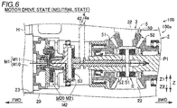
- the outboard motor 100 has three types of drive states. Specifically, the outboard motor 100 has three types of drive states including a "forward drive state” in which the propeller P2 is rotated by the driving force of the engine E to move the marine vessel 101 forward, a “reverse drive state” in which the propeller P2 is rotated by the driving force of the engine E to move the marine vessel 101 rearward, and a “motor drive state” in which the propeller P2 is rotated by the driving force of the electric motor M1 to move the marine vessel 101 (forward or rearward).
- the three types of drive states of the outboard motor 100 are switched by the switch 4.
- the shift shaft 4a bends halfway in the upward-downward direction, and a lower portion (second shift shaft 42 described below) thereof is spaced apart from and rearward of an upper portion (first shift shaft 41 described below). The details are described below. The structure of each portion of the outboard motor 100 is now described.
- the engine E is an internal combustion engine that generates a driving force by combustion of fuel.
- the engine E is disposed in the uppermost portion of the outboard motor body 100a.
- the engine E is connected to the upper end of the drive shaft 3 that extends in the upward-downward direction, and rotates the drive shaft 3 by the generated driving force (torque). Consequently, the engine E rotates the propeller P2 together with the propeller shaft P1.
- the electric motor M1 shown in FIG. 2 rotates the propeller P2 instead of the engine E (see FIG. 1 ).
- Electric power is supplied to the electric motor M1 via wiring H.
- the wiring H is connected to the electric motor M1 via a water passage (not shown) provided in the lower case 2.
- Cooling water water to cool each portion of the outboard motor 100
- a water pump WP flows through the water passage (not shown).
- the water pump WP is a positive-displacement water pump.
- the water pump WP is installed on the drive shaft 3 (second drive shaft 32), and rotates together with the drive shaft 3.
- the electric motor M1 includes a motor body M10 including a stator and a rotor, and a motor shaft M11 that functions as an output shaft that outputs the generated driving force (torque) to the outside.
- the electric motor M1 is disposed on an extension of the central axis ⁇ of the propeller shaft P1. That is, the motor shaft M11 is disposed coaxially with the central axis ⁇ of the propeller shaft P1.
- the electric motor M1 is disposed below (immediately below) the first shift shaft 41 and forward of the second shift shaft 42.
- the motor body M10 (electric motor M1) is disposed in a motor chamber 23 provided in the lower case 2.
- the motor chamber 23 is kept watertight.
- the propeller P2 is attached to the rear end of the propeller shaft P1, and is rotated integrally with the propeller shaft P1.
- the propeller shaft P1 is disposed in the lower case 2 and is disposed in an internal space chamber 22 positioned adjacent to the rear of the motor chamber 23.
- the rear of the internal space chamber 22 is open so as to be able to house the propeller shaft P1, and extends in the forward-rearward direction along the central axis ⁇ of the propeller shaft P1.
- the motor chamber 23 that houses the electric motor M1 is disposed adjacent to the front of the internal space chamber 22.
- the motor driving force transmitter M2 transmits the driving force of the electric motor M1 to the propeller shaft P1 when the drive state of the outboard motor 100 is the "motor drive state".
- the motor driving force transmitter M2 is disposed between the propeller shaft P1 and the electric motor M1 in the forward-rearward direction.
- a slider S (slide shifter), which is described below, of the switch 4 is disposed between the motor driving force transmitter M2 and the propeller shaft P1.
- the motor driving force transmitter M2 includes a planetary gear unit M20 rotated by the electric motor M1 (motor shaft M11) and an engaged portion M21 provided at the rear end of the planetary gear unit M20.
- the engaged portion M21 engages with (meshes with) a motor clutch S3 of the slider S that moves in the forward-rearward direction at the time of shift switching, and rotates integrally with the motor clutch S3 (slider S).
- the propeller shaft P1 is rotated via the slider S.
- the slider S is a shaft that extends in the forward-rearward direction.
- the cowling C (see FIG. 1 ) is disposed in the uppermost portion of the outboard motor 100.
- the cowling C houses the engine E (see FIG. 1 ) and an electric actuator 4b, which is described below, of the switch 4. Therefore, the upper end of (a first drive shaft 31 described below of) the drive shaft 3 and the upper end of (the first shift shaft 41 described below of) the shift shaft 4a are positioned inside the cowling C.
- the upper case 1 is disposed above the lower case 2 and below the cowling C.
- the upper case 1 is divided into a plurality of members (a plurality of upper pieces), and is configured by assembling the plurality of upper pieces with each other.
- a driving force transmitter 33, which is described below, of the drive shaft 3 is disposed (mounted) inside a predetermined upper piece 10 disposed at a substantially intermediate height in the upward-downward direction among the plurality of upper pieces. Therefore, the driving force transmitter 33 is positioned at the substantially intermediate height of the upper piece 10 in the upward-downward direction.
- the predetermined upper piece 10 has an elongated shape, the longitudinal direction of which is the forward-rearward direction as viewed in the right-left direction.
- the thickness of the predetermined upper piece 10 in the upward-downward direction is substantially constant as viewed in the right-left direction.
- the driving force transmitter 33 is attached to the predetermined upper piece 10 from below.
- the upper case 1 predetermined upper piece 10 includes a driving force transmitter housing chamber 11 that houses the driving force transmitter 33.
- the driving force transmitter housing chamber 11 includes recesses that are recessed upward from the lower end of the predetermined upper piece 10 and a lid 11a that closes the recesses.
- a shift force transmitter 43 is attached to the upper case 1 from below.
- a shift force transmitter housing chamber 13 that houses the shift force transmitter 43 is provided at the lower end of the upper case 1.
- the shift force transmitter housing chamber 13 includes recesses that are recessed upward from the lower end of the upper case 1 and a lid 13a that closes the recesses.
- a cylindrical steering shaft 12 that extends in the upward-downward direction is provided in a front portion of the upper case 1.
- the steering shaft 12 functions as a central axis about which the outboard motor 100 is rotated (turned) in the horizontal direction (steering direction) in order to change the traveling direction of the marine vessel 101.
- the lower end of the steering shaft 12 is positioned above a boundary between the upper case 1 and the lower case 2.
- the lower case 2 houses the propeller shaft P1 and the electric motor M1.
- the lower end of (the second drive shaft 32 described below of) the drive shaft 3 and the lower end of (the second shift shaft 42 described below of) the shift shaft 4a are positioned inside the lower case 2.
- the lower case 2 includes a streamlined torpedo 20 that extends in the forward-rearward direction, and an upper portion 21 that is connected to the torpedo 20 from above and is thin in the right-left direction.
- the torpedo 20 includes an intake port 20a at the tip of the torpedo 20, and cooling water that flows through a water passage (not shown) is taken in via the intake port 20a.
- the lower case 2 includes the motor chamber 23 in which the motor body M10 is disposed (housed), and the internal space chamber 22 in which the propeller shaft P1, the bevel gear unit 5, and the motor driving force transmitter M2 are disposed (housed).
- the drive shaft 3 transmits the driving force of the engine E (see FIG. 1 ) to the propeller shaft P1 that rotates together with the propeller P2.
- the drive shaft 3 is disposed at an intermediate position of the outboard motor 100 in the right-left direction (the same applies to the shift shaft 4a and the propeller shaft P1).
- the drive shaft 3 includes the first drive shaft 31 that extends in the upward-downward direction, the second drive shaft 32 that is disposed below the first drive shaft 31, is spaced apart from and rearward of the first drive shaft 31, and extends in the upward-downward direction, and the driving force transmitter 33 that transmits, to the second drive shaft 32, a driving force applied to the first drive shaft 31.
- the upper end of the first drive shaft 31 is positioned inside the cowling C.
- the lower end of the first drive shaft 31 is positioned inside the predetermined upper piece 10 of the upper case 1.
- the first drive shaft 31 is disposed forward of the propeller shaft P1.
- the first drive shaft 31 is disposed above the lower mounts LM.
- the driving force transmitter 33 includes a plurality of circular spur gears 33a aligned in the forward-rearward direction and in the horizontal direction.
- the plurality of spur gears 33a mesh with each other, and transmit a driving force from the front spur gear 33a to the rear spur gear 33a.
- the spur gear 33a at the front end is fixed to the lower end of the first drive shaft 31.
- the spur gear 33a at the rear end is fixed to the upper end of the second drive shaft 32.
- An odd number of spur gears 33a are provided for the outboard motor 100. Specifically, three spur gears 33a are provided for the outboard motor 100. Furthermore, the plurality of (three) spur gears 33a rotate about a central axis that extends in the upward-downward direction. That is, in the drive shaft 3, the rotation direction of the first drive shaft 31 and the rotation direction of the second drive shaft 32 are the same.
- the upper end of the second drive shaft 32 is disposed inside the predetermined upper piece 10 of the upper case 1.
- the lower end of the second drive shaft 32 is disposed inside the internal space chamber 22 of the lower case 2.
- An intermediate bevel gear 50 (a bevel gear disposed between a front bevel gear 51 and a rear bevel gear 52 in the forward-rearward direction), described below, of the bevel gear unit 5 is fixed to the lower end of the second drive shaft 32.
- the switch 4 includes the shift shaft 4a that is disposed forward of the drive shaft 3 and switches the shift state of the outboard motor 100, the electric actuator 4b that rotates the shift shaft 4a (moves the slider S in the forward-rearward direction), and the slider S that moves in the forward-rearward direction as the shift shaft 4a rotates.
- the shift shaft 4a includes the first shift shaft 41 that extends in the upward-downward direction, the second shift shaft 42 that is located below the first shift shaft 41, is spaced apart from and rearward of the first shift shaft 41, and extends in the upward-downward direction, and the shift force transmitter 43 that transmits a shift force applied to the first shift shaft 41 to the second shift shaft 42.
- the shift shaft 4a (excluding the upper end and the lower end) is disposed inside the cylindrical steering shaft 12 that extends in the upward-downward direction (is inserted in the steering shaft 12).
- the upper end of the first shift shaft 41 is disposed inside the cowling C, and the electric actuator 4b is installed.
- the lower end of the first shift shaft 41 is disposed inside the upper case 1.
- the lower end of the first shift shaft 41 is disposed in the vicinity of the boundary between the upper case 1 and the lower case 2.
- the shift force transmitter 43 includes a plurality of sector gears (43a and 43b) aligned in the forward-rearward direction and in the horizontal direction.
- the sector gears are a type of spur gears, and are gears in which teeth are only partially provided in the circumferential direction (rotation direction).
- the plurality of sector gears mesh with each other, and transmit a shift force from the front sector gear to the rear sector gear.
- the sector gear at the front end is fixed to the lower end of the first shift shaft 41.
- the sector gear at the rear end is fixed to the upper end of the second shift shaft 42.
- An odd number of sector gears are provided for the outboard motor 100. Specifically, three sector gears are provided for the outboard motor 100. Furthermore, the plurality of (three) sector gears rotate about a central axis that extends in the upward-downward direction. That is, in the shift shaft 4a, the rotation direction of the first shift shaft 41 and the rotation direction of the second shift shaft 42 are the same.
- the plurality of (three) sector gears include one elliptical gear 43a having a generally oval shape (a shape defined by a pair of parallel straight portions and a pair of arcuate portions) and a pair of (two) fan-shaped gears 43b disposed forward of and rearward of the elliptical gear 43a.
- the lengths of the shift force transmitter 43 in the right-left direction and the forward-rearward direction are smaller due to the elliptical gear 43a and the fan-shaped gears 43b as compared with a case in which the shift force transmitter 43 includes a plurality of circular gears.
- Both the elliptical gear 43a and the fan-shaped gear 43b are examples of a "spur gear” and a "sector gear”.
- the shift force transmitter 43 is disposed in the vicinity of the boundary between the upper case 1 and the lower case 2 so as to be exposed when the upper case 1 and the lower case 2 are separate from each other.
- the shift force transmitter 43 is exposed as described above when the upper case 1 and the lower case 2 are separate from each other. When the upper case 1 and the lower case 2 are separate from each other, the shift force transmitter 43 is not visually recognized until the lid 13a is removed.
- the upper end of the second shift shaft 42 is positioned inside the upper case 1.
- the lower end of the second shift shaft 42 is positioned inside the internal space chamber 22 of the lower case 2.
- the slider S is mounted at the lower end of the second shift shaft 42.
- the first shift shaft 41 is disposed forward of the first drive shaft 31 in the forward-rearward direction.
- the second shift shaft 42 is disposed rearward of the first drive shaft 31 in the forward-rearward direction. That is, the first drive shaft 31 is disposed between the first shift shaft 41 and the second shift shaft 42 in the forward-rearward direction. Therefore, as viewed in the upward-downward direction, a rear portion of the shift force transmitter 43 overlaps a front portion of the driving force transmitter 33.
- the shift force transmitter 43 is disposed below the driving force transmitter 33. Furthermore, the shift force transmitter 43 is disposed below the lower mounts LM.
- the rearward separation distance D1 of the second shift shaft 42 from the first shift shaft 41 is substantially equal to the rearward separation distance D2 of the second drive shaft 32 from the first drive shaft 31. Furthermore, the rearward separation distance D1 of the second shift shaft 42 from the first shift shaft 41 is larger than the length D3 of the electric motor M1 in the forward-rearward direction.
- the bevel gear unit 5 includes three gears including the intermediate bevel gear 50, the front bevel gear 51, and the rear bevel gear 52.
- the intermediate bevel gear 50 constantly meshes (engages) with the front bevel gear 51 and the rear bevel gear 52.
- the intermediate bevel gear 50 is fixed to the lower end of the second drive shaft 32.
- the front bevel gear 51 is disposed forward of the intermediate bevel gear 50.
- the rear bevel gear 52 is disposed rearward of the intermediate bevel gear 50.
- the intermediate bevel gear 50 functions as a drive gear that drives the front bevel gear 51 and the rear bevel gear 52. That is, the front bevel gear 51 and the rear bevel gear 52 function as driven gears of the intermediate bevel gear 50.
- the front bevel gear 51 and the rear bevel gear 52 rotate about the central axis ⁇ of the propeller shaft P1. The rotation directions of the front bevel gear 51 and the rear bevel gear 52 are opposite to each other.
- the switch 4 switches between three drive states including a "forward drive state”, a “reverse drive state”, and a “motor drive state” by moving the slider S in the forward-rearward direction.
- the slider S is a shaft disposed in the internal space chamber 22 and extending in the forward-rearward direction.
- the rear end of the slider S is connected to the propeller shaft P1 so as to be movable in a predetermined range in the forward-rearward direction with respect to the propeller shaft P1.
- the slider S moves forward when the shift shaft 4a rotates in a predetermined direction. Furthermore, the slider S moves rearward when the shift shaft 4a rotates in a direction opposite to the predetermined direction.
- the slider S includes a connector S1 provided in the vicinity of the rear end of the slider S, drive clutches S2 provided at the rear end of the slider S, and a motor clutch S3 provided at the front end of the slider S.
- the connector S1 connects the slider S to the propeller shaft P1.
- the connector S1 is a shaft that extends in a direction perpendicular to the forward-rearward direction.
- the connector S1 penetrates an elongated hole that extends in the forward-rearward direction of the propeller shaft P1.
- the drive clutches S2 are provided at both ends of the connector S1.
- the drive clutches S2 are dog clutches.
- the drive clutches S2 do not engage with either the front bevel gear 51 or the rear bevel gear 52 when the drive clutches S2 are located at intermediate positions (neutral positions) between positions at which the drive clutches S2 engage with the front bevel gear 51 and positions at which the drive clutches S2 engage with the rear bevel gear 52.
- the motor clutch S3 engages with the engaged portion M21 provided at the rear end of the planetary gear unit M20. Consequently, the drive state of the outboard motor 100 becomes the "motor drive state". In short, a driving force is transmitted from the electric motor M1 to the propeller shaft P1 via a path that passes through the planetary gear unit M20.
- the shift shaft 4a includes the first shift shaft 41 that extends in the upward-downward direction, the second shift shaft 42 that is disposed below the first shift shaft 41, is spaced apart from and rearward of the first shift shaft 41, and extends in the upward-downward direction, and the shift force transmitter 43 that transmits, to the second shift shaft 42, a shift force applied to the first shift shaft 41.
- the first shift shaft 41 which is an upper portion of the shift shaft 4a, is not disposed further rearward of the hull 102 (tilt shaft), but only the second shift shaft 42, which is a lower portion of the shift shaft 4a, is disposed further rearward.
- the second shift shaft 42 at a position at which it is likely to be submerged is partially disposed further rearward of the hull 102 (tilt shaft). Therefore, as compared with a case in which the entire outboard motor body 100a is disposed further rearward of the hull 102 (tilt shaft) as in the related art, the center of gravity of the outboard motor 100 is located closer to the hull 102. Consequently, submersion during tilting up of the outboard motor 100 is prevented while an increase in the weight of the outboard motor 100 is significantly reduced or prevented.
- the drive shaft 3 includes the first drive shaft 31 that extends in the upward-downward direction, the second drive shaft 32 that is disposed below the first drive shaft 31, is spaced apart from and rearward of the first drive shaft 31, and extends in the upward-downward direction, and the driving force transmitter 33 that transmits, to the second drive shaft 32, a driving force applied to the first drive shaft 31.
- the first drive shaft 31, which is an upper portion of the drive shaft 3 is not disposed further rearward of the hull 102 (tilt shaft), but only the second drive shaft 32, which is a lower portion of the drive shaft 3, is disposed further rearward. Consequently, the entire drive shaft 3 is prevented from being disposed further rearward.
- the center of gravity of the outboard motor 100 is located closer to the hull 102 such that an increase in the weight of the outboard motor 100 is effectively significantly reduced or prevented.
- the shift force transmitter 43 is disposed below the driving force transmitter 33. Accordingly, when the drive shaft 3 is disposed in the vicinity of the shift shaft 4a by design, the drive shaft 3 and the shift shaft 4a become less likely to interfere with each other. That is, the drive shaft 3 is disposed further forward (closer to the shift shaft 4a), and thus the center of gravity of the outboard motor 100 is located closer to the hull 102 such that an increase in the weight of the outboard motor 100 is more effectively significantly reduced or prevented.
- the rearward separation distance D1 of the second shift shaft 42 from the first shift shaft 41 is substantially equal to the rearward separation distance D2 of the second drive shaft 32 from the first drive shaft 31. Accordingly, a distance between the drive shaft 3 and the shift shaft 4a is kept substantially constant at any height. Therefore, as in a conventional case in which the drive shaft 3 and the shift shaft 4a extend linearly in the upward-downward direction, structures that are provided at the lower ends of the drive shaft 3 and the shift shaft 4a and switch the shift state of the outboard motor 100 and structures that transmit a driving force are used without a change in design.
- the outboard motor 100 includes the lower case 2 that houses the propeller shaft P1 and the upper case 1 disposed above the lower case 2, and the shift force transmitter 43 is disposed in the vicinity of the boundary between the upper case 1 and the lower case 2 so as to be exposed when the upper case 1 is separate from the lower case 2. Accordingly, the shift force transmitter 43 is disposed at a position at which it is exposed when the upper case 1 and the lower case 2 are separate from each other, and thus the shift force transmitter 43 is easily installed and maintained.
- the outboard motor 100 includes the electric motor M1 that rotates the propeller P2 in place of the engine E, and the electric motor M1 is disposed below the first shift shaft 41 and forward of the second shift shaft 42 on the extension of the central axis ⁇ of the propeller shaft P1. Accordingly, a space secured by disposing the lower portion of the shift shaft 4a rearward is effectively used as a space in which the electric motor M1 is disposed. Furthermore, the electric motor M1 is disposed coaxially with the propeller shaft P1, and thus the structure of the outboard motor 100 is simplified as compared with a case in which the electric motor M1 is offset from the central axis ⁇ of the propeller shaft P1.
- the rearward separation distance D1 of the second shift shaft 42 from the first shift shaft 41 is larger than the length D3 of the electric motor M1 in the forward-rearward direction. Accordingly, the outboard motor 100 is prevented from being likely to be submerged due to large forward protrusion of the electric motor M1 from the space secured by disposing the lower portion of the shift shaft 4a rearward.
- the driving force transmitter 33 includes the plurality of spur gears 33a (elliptical gear 43a and fan-shaped gears 43b) aligned in the forward-rearward direction, and the plurality of spur gears 33a (elliptical gear 43a and fan-shaped gears 43b) of the driving force transmitter 33 (shift force transmitter 43) include an odd number of spur gears 33a (elliptical gear 43a and fan-shaped gears 43b). Accordingly, the rotation directions of the first drive shaft 31 and the second drive shaft 32 (the rotation directions of the first shift shaft 41 and the second shift shaft 42) are prevented from being reversed.
- the shift force transmitter 43 includes the plurality of spur gears (elliptical gear 43a and fan-shaped gears 43b) aligned in the forward-rearward direction, and the plurality of spur gears include the plurality of sector gears in which teeth are only partially provided in the circumferential direction. Accordingly, as compared with a case in which the shift force transmitter 43 includes spur gears including circular teeth, the shift force transmitter 43 is downsized.
- the outboard motor 100 includes the cylindrical steering shaft 12 that extends in the upward-downward direction, and the first shift shaft 41 is disposed inside the steering shaft 12. Accordingly, the first shift shaft 41 is covered with the cylindrical steering shaft 12 so as to be protected.
- the outboard motor 100 includes the lower mounts LM that supports the lower portion of the outboard motor body 100a, and the shift force transmitter 43 is disposed below the lower mounts LM. Accordingly, the shift force transmitter 43 is disposed at a relatively low position. That is, in the upward-downward direction, only the lower portion of the shift shaft 4a located in a relatively small height range is disposed rearward. Therefore, rearward movement of the center of gravity of the outboard motor 100 is minimized, and thus an increase in the weight of the outboard motor 100 is effectively significantly reduced or prevented.
- the first shift shaft 41 is disposed forward of the first drive shaft 31 in the forward-rearward direction
- the second shift shaft 42 is disposed rearward of the first drive shaft 31 in the forward-rearward direction.
- the drive shaft 3 overlaps the shift shaft 4a in the forward-rearward direction. Therefore, the drive shaft 3 is disposed relatively close to the shift shaft 4a in the forward-rearward direction, and thus rearward movement of the center of gravity of the outboard motor 100 is minimized. Consequently, an increase in the weight of the outboard motor 100 is effectively significantly reduced or prevented.
- the distance between the shift force transmitter 43 and the driving force transmitter 33 in the upward-downward direction is larger than the distance between the first shift shaft 41 and the first drive shaft 31 in the forward-rearward direction. Accordingly, a relatively large space is secured between the shift force transmitter 43 and the driving force transmitter 33 in the upward-downward direction, and thus it is used as a space in which various components such as the lower mounts are disposed.
- an outboard motor 200 according to a second preferred embodiment is now described with reference to FIG. 7 .
- a driving force transmitter 233 of a drive shaft 203 is disposed below lower mounts LM, unlike the first preferred embodiment in which the drive force transmitter 33 of the drive shaft 3 is disposed above the lower mounts LM.
- the outboard motor 200 according to the second preferred embodiment also differs from the outboard motor 100 according to the first preferred embodiment in that the outboard motor 200 does not include an electric motor.
- the same or similar structures as those of the first preferred embodiment are denoted by the same reference numerals, and description thereof is omitted.
- the outboard motor 200 includes the drive shaft 203 and a water pump WP1.
- the drive shaft 203 includes the driving force transmitter 233.
- the driving force transmitter 233 is disposed below the lower mounts LM. A front portion of the driving force transmitter 233 is disposed immediately below the lower mounts LM. In addition, the driving force transmitter 233 is disposed above the shift force transmitter 43. The driving force transmitter 233 is disposed adjacent to or in the vicinity of the shift force transmitter 43.
- the water pump WP1 is a non-positive displacement water pump driven by a propeller shaft P1 to pump seawater so as to cool an engine.
- the water pump WP1 is disposed on an extension of the central axis ⁇ of the propeller shaft P1.
- the water pump WP1 is disposed below a first shift shaft 41 and forward of a second shift shaft 42.
- the water pump WP1 is directly installed at the front end of the propeller shaft P1, and is driven by the torque (driving force) of the propeller shaft P1.
- a rearward separation distance D20 of the second shift shaft 42 from the first shift shaft 41 is larger than the length D21 of the water pump WP1 in a forward-rearward direction.
- the outboard motor 200 includes the non-positive displacement water pump WP1 driven by the propeller shaft P1 to pump seawater so as to cool the engine E, and the water pump WP1 is disposed below the first shift shaft 41 and forward of the second shift shaft 42 on the extension of the central axis ⁇ of the propeller shaft P1. Accordingly, a space secured by disposing a lower portion of a shift shaft 4a rearward is effectively used as a space in which the water pump WP1 is disposed.
- the rearward separation distance D20 of the second shift shaft 42 from the first shift shaft 41 is larger than the length D21 of the water pump WP1 in the forward-rearward direction. Accordingly, the outboard motor 200 is prevented from being likely to be submerged due to large forward protrusion of the water pump WP1 from the space secured by disposing the lower portion of the shift shaft 4a rearward.
- the outboard motor 200 includes the lower mounts LM that support a lower portion of an outboard motor body, and the driving force transmitter 233 is disposed below the lower mounts LM. Accordingly, the driving force transmitter 233 is disposed at a relatively low position. That is, only a lower portion of the drive shaft 203 located in a relatively small height range is disposed rearward in an upward-downward direction. Therefore, rearward movement of the center of gravity of the outboard motor 200 is minimized, and thus an increase in the weight of the outboard motor 200 is effectively significantly reduced or prevented.
- the driving force transmitter (shift force transmitter) preferably includes three spur gears in each of the first and second preferred embodiments described above, the present teaching is not restricted to this.
- the driving force transmitter may alternatively include two or four or more spur gears. The number of spur gears is preferably odd.
- the shift force transmitter is preferably disposed inside the upper case in each of the first and second preferred embodiments described above, the present teaching is not restricted to this. In the present teaching, the shift force transmitter may alternatively be disposed inside the lower case.
- the lower portion (second drive shaft) of the drive shaft is preferably located rearward in each of the first and second preferred embodiments described above, the present teaching is not restricted to this.
- the drive shaft may alternatively extend linearly in the upward-downward direction.
- the shift force transmitter is preferably disposed below the lower mounts in each of the first and second preferred embodiments described above, the present teaching is not restricted to this.
- the shift force transmitter may alternatively be disposed above the lower mounts.
- the shift force transmitter may alternatively be disposed at the same height as the lower mounts.
- the shift force transmitter (driving force transmitter) preferably includes a plurality of spur gears in each of the first and second preferred embodiments described above, the present teaching is not restricted to this.
- the shift force transmitter (driving force transmitter) may alternatively include a plurality of bevel gears, for example.
- components such as the electric motor and the water pump are preferably disposed forward on the extension of the central axis of the propeller shaft, respectively, in the first and second preferred embodiments described above, the present teaching is not restricted to this. In the present teaching, components such as the electric motor and the water pump may not be disposed forward on the extension of the central axis of the propeller shaft.
- the marine vessel While when the slider moves forward such that the front bevel gear and the drive clutches of the slider mesh with each other, the marine vessel is preferably moved forward, and when the slider moves rearward such that the rear bevel gear and the drive clutches mesh with each other, the marine vessel is preferably moved rearward in each of the first and second preferred embodiments described above, the present teaching is not restricted to this.
- the marine vessel when the slider moves forward such that the front bevel gear and the drive clutches mesh with each other, the marine vessel may alternatively be moved rearward, and when the slider moves rearward such that the rear bevel gear and the drive clutches mesh with each other, the marine vessel may alternatively be moved forward.
Abstract
Description
- The present invention relates to an outboard motor including a shift shaft that switches the shift state of the outboard motor and to a marine vessel including a hull and an outboard motor.
- An outboard motor including a shift shaft that switches the shift state of the outboard motor is known in general. Such an outboard motor is disclosed in
JP 2004-211619 A -
JP 2004-211619 A - The lower end of the shift shaft is positioned in the vicinity of the front end of the lower case. The front end of the lower case (a portion of the lower case in the vicinity of the lower end of the shift shaft) is located at a position at which the front end is likely to be submerged when the outboard motor is tilted up (when an outboard motor body is tilted about a tilt shaft that extends in a right-left direction such that the lower end of the outboard motor body moves rearward). The outboard motor body is mounted on a hull by a bracket.
- Although not clearly described in
JP 2004-211619 A JP 2004-211619 A - It is an object of the present invention to provide an outboard motor and a marine vessel including a hull and an outboard motor that prevents submersion during tilting up of the outboard motor while significantly reducing or preventing an increase in the weight of the outboard motor. According to the present invention, said object is solved by an outboard motor having the features of
independent claim 1. Moreover, said object is solved by a marine vessel including a hull and an outboard motor according to claim 16. Preferred embodiments are laid down in the dependent claims. - An outboard motor according to a preferred embodiment includes an engine, a drive shaft configured to transmit a driving force from the engine to a propeller shaft configured to rotate together with a propeller, and a shift shaft disposed forward of the drive shaft, the shift shaft being configured to switch a shift state of the outboard motor. The shift shaft includes a first shift shaft configured to extend in an upward-downward direction, a second shift shaft disposed below the first shift shaft and spaced apart from and rearward of the first shift shaft, the second shift shaft being configured to extend in the upward-downward direction, and a shift force transmitter configured to transmit, to the second shift shaft, a shift force applied to the first shift shaft.
- In an outboard motor according to a preferred embodiment, the shift shaft includes the first shift shaft configured to extend in the upward-downward direction, the second shift shaft disposed below the first shift shaft and spaced apart from and rearward of the first shift shaft, the second shift shaft being configured to extend in the upward-downward direction, and the shift force transmitter configured to transmit, to the second shift shaft, a shift force applied to the first shift shaft. Accordingly, unlike the related art, the first shift shaft, which is an upper portion of the shift shaft, is not disposed further rearward of a hull (tilt shaft), but only the second shift shaft, which is a lower portion of the shift shaft, is disposed further rearward. That is, in the outboard motor, only the second shift shaft at a position at which it is likely to be submerged is partially disposed further rearward of the hull (tilt shaft). Therefore, as compared with a case in which an entire outboard motor body is disposed further rearward of the hull (tilt shaft) as in the related art, the center of gravity of the outboard motor is located closer to the hull. Consequently, submersion during tilting up of the outboard motor is prevented while an increase in the weight of the outboard motor is significantly reduced or prevented.
- In an outboard motor according to a preferred embodiment, the drive shaft preferably includes a first drive shaft configured to extend in the upward-downward direction, a second drive shaft disposed below the first drive shaft and spaced apart from and rearward of the first drive shaft, the second drive shaft being configured to extend in the upward-downward direction, and a driving force transmitter configured to transmit, to the second drive shaft, a driving force applied to the first drive shaft. Accordingly, similarly to the shift shaft, the first drive shaft, which is an upper portion of the drive shaft, is not disposed further rearward of the hull (tilt shaft), but only the second drive shaft, which is a lower portion of the drive shaft, is disposed further rearward. Consequently, the entire drive shaft is prevented from being disposed further rearward. Thus, the center of gravity of the outboard motor is located closer to the hull such that an increase in the weight of the outboard motor is effectively significantly reduced or prevented.
- In such a case, the shift force transmitter is preferably disposed below the driving force transmitter. Accordingly, when the drive shaft is disposed in the vicinity of the shift shaft by design, the drive shaft and the shift shaft become less likely to interfere with each other. That is, the drive shaft is disposed further forward (closer to the shift shaft), and thus the center of gravity of the outboard motor is located closer to the hull such that an increase in the weight of the outboard motor is more effectively significantly reduced or prevented.
- In an outboard motor including the drive shaft including the first drive shaft, the second drive shaft, and the driving force transmitter, a rearward separation distance of the second shift shaft from the first shift shaft is preferably equal to a rearward separation distance of the second drive shaft from the first drive shaft. Accordingly, a distance between the drive shaft and the shift shaft is kept substantially constant at any height. Therefore, as in a conventional case in which the drive shaft and the shift shaft extend linearly in the upward-downward direction, structures that are provided at the lower ends of the drive shaft and the shift shaft and switch the shift state of the outboard motor and structures that transmit a driving force are used without a change in design.
- An outboard motor according to a preferred embodiment preferably further includes a lower case configured to house the propeller shaft, and an upper case disposed above the lower case, and the shift force transmitter is preferably disposed in a vicinity of a boundary between the upper case and the lower case so as to be exposed when the upper case is separate from the lower case. Accordingly, the shift force transmitter is disposed at a position at which it is exposed when the upper case and the lower case are separate from each other, and thus the shift force transmitter is easily installed and maintained.
- An outboard motor according to a preferred embodiment preferably further includes an electric motor configured to rotate the propeller in place of the engine, and the electric motor is preferably disposed below the first shift shaft and forward of the second shift shaft on an extension of a central axis of the propeller shaft. Accordingly, a space secured by disposing the lower portion of the shift shaft rearward is effectively used as a space in which the electric motor is disposed. Furthermore, the electric motor is disposed coaxially with the propeller shaft, and thus the structure of the outboard motor is simplified as compared with a case in which the electric motor is offset from the central axis of the propeller shaft.
- In such a case, a rearward separation distance of the second shift shaft from the first shift shaft is preferably larger than a length of the electric motor in a forward-rearward direction. Accordingly, the outboard motor is prevented from being likely to be submerged due to large forward protrusion of the electric motor from the space secured by disposing the lower portion of the shift shaft rearward.
- In an outboard motor including the drive shaft including the first drive shaft, the second drive shaft, and the driving force transmitter, at least one of the shift force transmitter and the driving force transmitter preferably includes a plurality of spur gears aligned in a forward-rearward direction, and the plurality of spur gears of at least one of the shift force transmitter and the driving force transmitter preferably include an odd number of spur gears. Accordingly, the rotation directions of the first drive shaft and the second drive shaft (the rotation directions of the first shift shaft and the second shift shaft) are prevented from being reversed. That is, the rotation directions of the upper end and the lower end of the drive shaft (shift shaft) are the same. Therefore, as in a conventional case in which the drive shaft and the shift shaft extend linearly in the upward-downward direction, structures that are provided at the lower ends of the drive shaft and the shift shaft and switch the shift state of the outboard motor and structures that transmit a driving force are used without a change in design.
- In an outboard motor according to a preferred embodiment, the shift force transmitter preferably includes a plurality of spur gears aligned in a forward-rearward direction, and the plurality of spur gears preferably include a plurality of sector gears in which teeth are only partially provided in a circumferential direction. Accordingly, as compared with a case in which the shift force transmitter includes spur gears including circular teeth, the shift force transmitter is downsized.
- An outboard motor according to a preferred embodiment preferably further includes a cylindrical steering shaft configured to extend in the upward-downward direction, and the first shift shaft is preferably disposed inside the cylindrical steering shaft. Accordingly, the first shift shaft is covered with the cylindrical steering shaft so as to be protected.
- An outboard motor according to a preferred embodiment preferably further includes a non-positive displacement water pump driven by the propeller shaft to pump seawater so as to cool the engine, and the non-positive displacement water pump is preferably disposed below the first shift shaft and forward of the second shift shaft on an extension of a central axis of the propeller shaft. Accordingly, the space secured by disposing the lower portion of the shift shaft rearward is effectively used as a space in which the non-positive displacement water pump is disposed.
- In such a case, a rearward separation distance of the second shift shaft from the first shift shaft is preferably larger than a length of the non-positive displacement water pump in a forward-rearward direction. Accordingly, the outboard motor is prevented from being likely to be submerged due to large forward protrusion of the non-positive displacement water pump from the space secured by disposing the lower portion of the shift shaft rearward.
- An outboard motor according to a preferred embodiment preferably further includes a lower mount configured to support a lower portion of an outboard motor body, and the shift force transmitter is preferably disposed below the lower mount. Accordingly, the shift force transmitter is disposed at a relatively low position. That is, in the upward-downward direction, only the lower portion of the shift shaft located in a relatively small height range is disposed rearward. Therefore, rearward movement of the center of gravity of the outboard motor is minimized, and thus an increase in the weight of the outboard motor is effectively significantly reduced or prevented.
- An outboard motor including the drive shaft including the first drive shaft, the second drive shaft, and the driving force transmitter preferably further includes a lower mount configured to support a lower portion of an outboard motor body, and the driving force transmitter is preferably disposed below the lower mount. Accordingly, the driving force transmitter is disposed at a relatively low position. That is, only a lower portion of the drive shaft located in a relatively small height range is disposed rearward in an upward-downward direction. Therefore, rearward movement of the center of gravity of the outboard motor is minimized, and thus an increase in the weight of the outboard motor is effectively significantly reduced or prevented.
- In an outboard motor including the drive shaft including the first drive shaft, the second drive shaft, and the driving force transmitter, the first shift shaft is preferably disposed forward of the first drive shaft in a forward-rearward direction, and the second shift shaft is preferably disposed rearward of the first drive shaft in the forward-rearward direction. Accordingly, the drive shaft overlaps the shift shaft in the forward-rearward direction. Therefore, the drive shaft is disposed relatively close to the shift shaft in the forward-rearward direction, and thus rearward movement of the center of gravity of the outboard motor is minimized. Consequently, an increase in the weight of the outboard motor is effectively significantly reduced or prevented.
- The above and other elements, features, steps, characteristics and advantages of preferred embodiments will become more apparent from the following detailed description of the preferred embodiments with reference to the attached drawings.
-
-
FIG. 1 is a side view schematically showing the overall structure of an outboard motor according to a first preferred embodiment. -
FIG. 2 is a partial sectional view showing the structure of the outboard motor according to the first preferred embodiment. -
FIG. 3 is a bottom view showing a plurality of gears of a shift force transmitter of a shift shaft according to the first preferred embodiment. -
FIG. 4 is a partially enlarged view showing the inside of a lower case in a forward drive state by an engine of the outboard motor according to the first preferred embodiment. -
FIG. 5 is a partially enlarged view showing the inside of the lower case in a reverse drive state by the engine of the outboard motor according to the first preferred embodiment. -
FIG. 6 is a partially enlarged view showing the inside of the lower case in a motor drive state by an electric motor of the outboard motor according to the first preferred embodiment. -
FIG. 7 is a partial sectional view showing the structure of an outboard motor according to a second preferred embodiment. - Preferred embodiments are hereinafter described with reference to the drawings.
- The structure of a
marine vessel 101 and anoutboard motor 100 according to a first preferred embodiment is now described with reference toFIGS. 1 to 6 . - As shown in
FIG. 1 , themarine vessel 101 includes ahull 102 and theoutboard motor 100 attached to a portion (rear portion) of thehull 102 in a BWD direction. - In the following description, the term "front (forward)" refers to the forward movement direction (a direction indicated by "FWD" in the figures) of the
marine vessel 101, and the term "rear (rearward)" refers to a direction indicated by "BWD" in the figures. Furthermore, a "forward-rearward direction" refers to the forward-rearward direction of the marine vessel 101 (outboard motor 100) and a direction (a direction along the central axis α of a propeller shaft P1) parallel to the propeller shaft P1, for example. An "upward-downward direction" refers to the trim-tilt direction of theoutboard motor 100, an "upward direction" refers to an "arrow Z1 direction", and a "downward direction" refers to an "arrow Z2 direction". A "right-left direction" refers to a direction perpendicular to the upward-downward direction and a direction perpendicular to the forward-rearward direction. A "horizontal direction" refers to a direction along a horizontal plane perpendicular to the upward-downward direction and a steering direction. - The
outboard motor 100 includes a bracket B that fixes theoutboard motor 100 to thehull 102, a trim-tilt device T provided on the bracket B, lower mounts LM and upper mounts (not shown) provided on the bracket B. - The trim-tilt device T includes a cylinder, and rotates an
outboard motor body 100a in the trim-tilt direction about a tilt shaft T1 that extends in the right-left direction by expanding and contracting the cylinder. - The lower mounts LM support a lower portion of the
outboard motor body 100a (upper case 1) from the front side. The lower mounts LM are disposed in a lower portion of theupper case 1 in the upward-downward direction. Although not shown, the lower mounts LM (two in total) are spaced apart in the right-left direction so as to sandwich ashift shaft 4a from opposite sides in the right-left direction. Theoutboard motor body 100a in this description refers to an entire structure supported by the lower mounts LM and the upper mounts. - The outboard motor 100 (
outboard motor body 100a) further includes an engine E, an electric motor M1, the propeller shaft P1, a propeller P2, a motor driving force transmitter M2, a cowling C, theupper case 1, alower case 2, adrive shaft 3, aswitch 4 including theshift shaft 4a, and abevel gear unit 5. - The
outboard motor 100 has three types of drive states. Specifically, theoutboard motor 100 has three types of drive states including a "forward drive state" in which the propeller P2 is rotated by the driving force of the engine E to move themarine vessel 101 forward, a "reverse drive state" in which the propeller P2 is rotated by the driving force of the engine E to move themarine vessel 101 rearward, and a "motor drive state" in which the propeller P2 is rotated by the driving force of the electric motor M1 to move the marine vessel 101 (forward or rearward). The three types of drive states of theoutboard motor 100 are switched by theswitch 4. - The
shift shaft 4a according to the first preferred embodiment bends halfway in the upward-downward direction, and a lower portion (second shift shaft 42 described below) thereof is spaced apart from and rearward of an upper portion (first shift shaft 41 described below). The details are described below. The structure of each portion of theoutboard motor 100 is now described. - The engine E is an internal combustion engine that generates a driving force by combustion of fuel.
- The engine E is disposed in the uppermost portion of the
outboard motor body 100a. The engine E is connected to the upper end of thedrive shaft 3 that extends in the upward-downward direction, and rotates thedrive shaft 3 by the generated driving force (torque). Consequently, the engine E rotates the propeller P2 together with the propeller shaft P1. - The electric motor M1 shown in
FIG. 2 rotates the propeller P2 instead of the engine E (seeFIG. 1 ). Electric power is supplied to the electric motor M1 via wiring H. The wiring H is connected to the electric motor M1 via a water passage (not shown) provided in thelower case 2. Cooling water (water to cool each portion of the outboard motor 100) pumped by a water pump WP flows through the water passage (not shown). The water pump WP is a positive-displacement water pump. The water pump WP is installed on the drive shaft 3 (second drive shaft 32), and rotates together with thedrive shaft 3. - The electric motor M1 includes a motor body M10 including a stator and a rotor, and a motor shaft M11 that functions as an output shaft that outputs the generated driving force (torque) to the outside.
- The electric motor M1 is disposed on an extension of the central axis α of the propeller shaft P1. That is, the motor shaft M11 is disposed coaxially with the central axis α of the propeller shaft P1. The electric motor M1 is disposed below (immediately below) the
first shift shaft 41 and forward of thesecond shift shaft 42. The motor body M10 (electric motor M1) is disposed in amotor chamber 23 provided in thelower case 2. Themotor chamber 23 is kept watertight. - The propeller P2 is attached to the rear end of the propeller shaft P1, and is rotated integrally with the propeller shaft P1. The propeller shaft P1 is disposed in the
lower case 2 and is disposed in aninternal space chamber 22 positioned adjacent to the rear of themotor chamber 23. The rear of theinternal space chamber 22 is open so as to be able to house the propeller shaft P1, and extends in the forward-rearward direction along the central axis α of the propeller shaft P1. Themotor chamber 23 that houses the electric motor M1 is disposed adjacent to the front of theinternal space chamber 22. - The motor driving force transmitter M2 transmits the driving force of the electric motor M1 to the propeller shaft P1 when the drive state of the
outboard motor 100 is the "motor drive state". The motor driving force transmitter M2 is disposed between the propeller shaft P1 and the electric motor M1 in the forward-rearward direction. A slider S (slide shifter), which is described below, of theswitch 4 is disposed between the motor driving force transmitter M2 and the propeller shaft P1. - The motor driving force transmitter M2 includes a planetary gear unit M20 rotated by the electric motor M1 (motor shaft M11) and an engaged portion M21 provided at the rear end of the planetary gear unit M20.
- The engaged portion M21 engages with (meshes with) a motor clutch S3 of the slider S that moves in the forward-rearward direction at the time of shift switching, and rotates integrally with the motor clutch S3 (slider S). Thus, the propeller shaft P1 is rotated via the slider S. The slider S is a shaft that extends in the forward-rearward direction.
- The cowling C (see
FIG. 1 ) is disposed in the uppermost portion of theoutboard motor 100. The cowling C houses the engine E (seeFIG. 1 ) and anelectric actuator 4b, which is described below, of theswitch 4. Therefore, the upper end of (afirst drive shaft 31 described below of) thedrive shaft 3 and the upper end of (thefirst shift shaft 41 described below of) theshift shaft 4a are positioned inside the cowling C. - As shown in
FIG. 2 , theupper case 1 is disposed above thelower case 2 and below the cowling C. Theupper case 1 is divided into a plurality of members (a plurality of upper pieces), and is configured by assembling the plurality of upper pieces with each other. - A driving
force transmitter 33, which is described below, of thedrive shaft 3 is disposed (mounted) inside a predeterminedupper piece 10 disposed at a substantially intermediate height in the upward-downward direction among the plurality of upper pieces. Therefore, the drivingforce transmitter 33 is positioned at the substantially intermediate height of theupper piece 10 in the upward-downward direction. - The predetermined
upper piece 10 has an elongated shape, the longitudinal direction of which is the forward-rearward direction as viewed in the right-left direction. The thickness of the predeterminedupper piece 10 in the upward-downward direction is substantially constant as viewed in the right-left direction. - The driving
force transmitter 33 is attached to the predeterminedupper piece 10 from below. Specifically, the upper case 1 (predetermined upper piece 10) includes a driving forcetransmitter housing chamber 11 that houses the drivingforce transmitter 33. The driving forcetransmitter housing chamber 11 includes recesses that are recessed upward from the lower end of the predeterminedupper piece 10 and alid 11a that closes the recesses. - A
shift force transmitter 43 is attached to theupper case 1 from below. Specifically, a shift forcetransmitter housing chamber 13 that houses theshift force transmitter 43 is provided at the lower end of theupper case 1. The shift forcetransmitter housing chamber 13 includes recesses that are recessed upward from the lower end of theupper case 1 and alid 13a that closes the recesses. - A
cylindrical steering shaft 12 that extends in the upward-downward direction is provided in a front portion of theupper case 1. The steeringshaft 12 functions as a central axis about which theoutboard motor 100 is rotated (turned) in the horizontal direction (steering direction) in order to change the traveling direction of themarine vessel 101. The lower end of the steeringshaft 12 is positioned above a boundary between theupper case 1 and thelower case 2. - The
lower case 2 houses the propeller shaft P1 and the electric motor M1. The lower end of (thesecond drive shaft 32 described below of) thedrive shaft 3 and the lower end of (thesecond shift shaft 42 described below of) theshift shaft 4a are positioned inside thelower case 2. - The
lower case 2 includes astreamlined torpedo 20 that extends in the forward-rearward direction, and anupper portion 21 that is connected to thetorpedo 20 from above and is thin in the right-left direction. Thetorpedo 20 includes anintake port 20a at the tip of thetorpedo 20, and cooling water that flows through a water passage (not shown) is taken in via theintake port 20a. - As described above, the
lower case 2 includes themotor chamber 23 in which the motor body M10 is disposed (housed), and theinternal space chamber 22 in which the propeller shaft P1, thebevel gear unit 5, and the motor driving force transmitter M2 are disposed (housed). - The
drive shaft 3 transmits the driving force of the engine E (seeFIG. 1 ) to the propeller shaft P1 that rotates together with the propeller P2. Although not shown, thedrive shaft 3 is disposed at an intermediate position of theoutboard motor 100 in the right-left direction (the same applies to theshift shaft 4a and the propeller shaft P1). - The
drive shaft 3 includes thefirst drive shaft 31 that extends in the upward-downward direction, thesecond drive shaft 32 that is disposed below thefirst drive shaft 31, is spaced apart from and rearward of thefirst drive shaft 31, and extends in the upward-downward direction, and the drivingforce transmitter 33 that transmits, to thesecond drive shaft 32, a driving force applied to thefirst drive shaft 31. - The upper end of the
first drive shaft 31 is positioned inside the cowling C. The lower end of thefirst drive shaft 31 is positioned inside the predeterminedupper piece 10 of theupper case 1. In the forward-rearward direction, thefirst drive shaft 31 is disposed forward of the propeller shaft P1. Thefirst drive shaft 31 is disposed above the lower mounts LM. - The driving
force transmitter 33 includes a plurality ofcircular spur gears 33a aligned in the forward-rearward direction and in the horizontal direction. The plurality ofspur gears 33a mesh with each other, and transmit a driving force from thefront spur gear 33a to therear spur gear 33a. Thespur gear 33a at the front end is fixed to the lower end of thefirst drive shaft 31. Thespur gear 33a at the rear end is fixed to the upper end of thesecond drive shaft 32. - An odd number of
spur gears 33a are provided for theoutboard motor 100. Specifically, threespur gears 33a are provided for theoutboard motor 100. Furthermore, the plurality of (three)spur gears 33a rotate about a central axis that extends in the upward-downward direction. That is, in thedrive shaft 3, the rotation direction of thefirst drive shaft 31 and the rotation direction of thesecond drive shaft 32 are the same. - The upper end of the
second drive shaft 32 is disposed inside the predeterminedupper piece 10 of theupper case 1. The lower end of thesecond drive shaft 32 is disposed inside theinternal space chamber 22 of thelower case 2. - An intermediate bevel gear 50 (a bevel gear disposed between a
front bevel gear 51 and arear bevel gear 52 in the forward-rearward direction), described below, of thebevel gear unit 5 is fixed to the lower end of thesecond drive shaft 32. - The
switch 4 includes theshift shaft 4a that is disposed forward of thedrive shaft 3 and switches the shift state of theoutboard motor 100, theelectric actuator 4b that rotates theshift shaft 4a (moves the slider S in the forward-rearward direction), and the slider S that moves in the forward-rearward direction as theshift shaft 4a rotates. - The
shift shaft 4a includes thefirst shift shaft 41 that extends in the upward-downward direction, thesecond shift shaft 42 that is located below thefirst shift shaft 41, is spaced apart from and rearward of thefirst shift shaft 41, and extends in the upward-downward direction, and theshift force transmitter 43 that transmits a shift force applied to thefirst shift shaft 41 to thesecond shift shaft 42. - The
shift shaft 4a (excluding the upper end and the lower end) is disposed inside thecylindrical steering shaft 12 that extends in the upward-downward direction (is inserted in the steering shaft 12). - The upper end of the
first shift shaft 41 is disposed inside the cowling C, and theelectric actuator 4b is installed. The lower end of thefirst shift shaft 41 is disposed inside theupper case 1. The lower end of thefirst shift shaft 41 is disposed in the vicinity of the boundary between theupper case 1 and thelower case 2. - The
shift force transmitter 43 includes a plurality of sector gears (43a and 43b) aligned in the forward-rearward direction and in the horizontal direction. The sector gears are a type of spur gears, and are gears in which teeth are only partially provided in the circumferential direction (rotation direction). The plurality of sector gears mesh with each other, and transmit a shift force from the front sector gear to the rear sector gear. The sector gear at the front end is fixed to the lower end of thefirst shift shaft 41. The sector gear at the rear end is fixed to the upper end of thesecond shift shaft 42. - An odd number of sector gears are provided for the
outboard motor 100. Specifically, three sector gears are provided for theoutboard motor 100. Furthermore, the plurality of (three) sector gears rotate about a central axis that extends in the upward-downward direction. That is, in theshift shaft 4a, the rotation direction of thefirst shift shaft 41 and the rotation direction of thesecond shift shaft 42 are the same. - As shown in
FIG. 3 , the plurality of (three) sector gears include oneelliptical gear 43a having a generally oval shape (a shape defined by a pair of parallel straight portions and a pair of arcuate portions) and a pair of (two) fan-shapedgears 43b disposed forward of and rearward of theelliptical gear 43a. Note that the lengths of theshift force transmitter 43 in the right-left direction and the forward-rearward direction are smaller due to theelliptical gear 43a and the fan-shapedgears 43b as compared with a case in which theshift force transmitter 43 includes a plurality of circular gears. Both theelliptical gear 43a and the fan-shapedgear 43b are examples of a "spur gear" and a "sector gear". - As shown in
FIG. 2 , theshift force transmitter 43 is disposed in the vicinity of the boundary between theupper case 1 and thelower case 2 so as to be exposed when theupper case 1 and thelower case 2 are separate from each other. - Specifically, the
shift force transmitter 43 is exposed as described above when theupper case 1 and thelower case 2 are separate from each other. When theupper case 1 and thelower case 2 are separate from each other, theshift force transmitter 43 is not visually recognized until thelid 13a is removed. - The upper end of the
second shift shaft 42 is positioned inside theupper case 1. The lower end of thesecond shift shaft 42 is positioned inside theinternal space chamber 22 of thelower case 2. - The slider S is mounted at the lower end of the
second shift shaft 42. - The
first shift shaft 41 is disposed forward of thefirst drive shaft 31 in the forward-rearward direction. Thesecond shift shaft 42 is disposed rearward of thefirst drive shaft 31 in the forward-rearward direction. That is, thefirst drive shaft 31 is disposed between thefirst shift shaft 41 and thesecond shift shaft 42 in the forward-rearward direction. Therefore, as viewed in the upward-downward direction, a rear portion of theshift force transmitter 43 overlaps a front portion of the drivingforce transmitter 33. - The
shift force transmitter 43 is disposed below the drivingforce transmitter 33. Furthermore, theshift force transmitter 43 is disposed below the lower mounts LM. - As shown in
FIG. 1 , the rearward separation distance D1 of thesecond shift shaft 42 from thefirst shift shaft 41 is substantially equal to the rearward separation distance D2 of thesecond drive shaft 32 from thefirst drive shaft 31. Furthermore, the rearward separation distance D1 of thesecond shift shaft 42 from thefirst shift shaft 41 is larger than the length D3 of the electric motor M1 in the forward-rearward direction. - Before the structure of the slider S of the
switch 4 is described with reference toFIG. 2 , the structure of thebevel gear unit 5 is described. - The
bevel gear unit 5 includes three gears including theintermediate bevel gear 50, thefront bevel gear 51, and therear bevel gear 52. - The
intermediate bevel gear 50 constantly meshes (engages) with thefront bevel gear 51 and therear bevel gear 52. Theintermediate bevel gear 50 is fixed to the lower end of thesecond drive shaft 32. Thefront bevel gear 51 is disposed forward of theintermediate bevel gear 50. Therear bevel gear 52 is disposed rearward of theintermediate bevel gear 50. - The
intermediate bevel gear 50 functions as a drive gear that drives thefront bevel gear 51 and therear bevel gear 52. That is, thefront bevel gear 51 and therear bevel gear 52 function as driven gears of theintermediate bevel gear 50. Thefront bevel gear 51 and therear bevel gear 52 rotate about the central axis α of the propeller shaft P1. The rotation directions of thefront bevel gear 51 and therear bevel gear 52 are opposite to each other. - The
switch 4 switches between three drive states including a "forward drive state", a "reverse drive state", and a "motor drive state" by moving the slider S in the forward-rearward direction. - In the "forward drive state" and the "reverse drive state", the engine E (see
FIG. 1 ) rotates the propeller P2, and in the "motor drive state", the electric motor M1 rotates the propeller P2. - The slider S is a shaft disposed in the
internal space chamber 22 and extending in the forward-rearward direction. The rear end of the slider S is connected to the propeller shaft P1 so as to be movable in a predetermined range in the forward-rearward direction with respect to the propeller shaft P1. The slider S moves forward when theshift shaft 4a rotates in a predetermined direction. Furthermore, the slider S moves rearward when theshift shaft 4a rotates in a direction opposite to the predetermined direction. - The slider S includes a connector S1 provided in the vicinity of the rear end of the slider S, drive clutches S2 provided at the rear end of the slider S, and a motor clutch S3 provided at the front end of the slider S.
- The connector S1 connects the slider S to the propeller shaft P1. The connector S1 is a shaft that extends in a direction perpendicular to the forward-rearward direction. The connector S1 penetrates an elongated hole that extends in the forward-rearward direction of the propeller shaft P1.
- The drive clutches S2 are provided at both ends of the connector S1. The drive clutches S2 are dog clutches.
- As shown in
FIG. 4 , when the slider S moves forward, the drive clutches S2 move forward together with the slider S and engage with thefront bevel gear 51 from the rear. Consequently, the drive state of theoutboard motor 100 becomes the "forward drive state". In short, a driving force is transmitted from thedrive shaft 3 to the propeller shaft P1 via a path that passes through thefront bevel gear 51. In such a case, the motor clutch S3 does not engage with the engaged portion M21 of the planetary gear unit M20. - As shown in
FIG. 5 , when the slider S moves rearward, the drive clutches S2 move rearward together with the slider S and engage with therear bevel gear 52 from the front. Consequently, the drive state of theoutboard motor 100 becomes the "reverse drive state". In short, a driving force is transmitted from thedrive shaft 3 to the propeller shaft P1 via a path that passes through therear bevel gear 52. In such a case, the motor clutch S3 does not engage with the engaged portion M21 of the planetary gear unit M20. - As shown in
FIG. 6 , the drive clutches S2 do not engage with either thefront bevel gear 51 or therear bevel gear 52 when the drive clutches S2 are located at intermediate positions (neutral positions) between positions at which the drive clutches S2 engage with thefront bevel gear 51 and positions at which the drive clutches S2 engage with therear bevel gear 52. In such a case, the motor clutch S3 engages with the engaged portion M21 provided at the rear end of the planetary gear unit M20. Consequently, the drive state of theoutboard motor 100 becomes the "motor drive state". In short, a driving force is transmitted from the electric motor M1 to the propeller shaft P1 via a path that passes through the planetary gear unit M20. - According to the first preferred embodiment, the following advantageous effects are achieved.
- According to the first preferred embodiment, the
shift shaft 4a includes thefirst shift shaft 41 that extends in the upward-downward direction, thesecond shift shaft 42 that is disposed below thefirst shift shaft 41, is spaced apart from and rearward of thefirst shift shaft 41, and extends in the upward-downward direction, and theshift force transmitter 43 that transmits, to thesecond shift shaft 42, a shift force applied to thefirst shift shaft 41. Accordingly, unlike the related art, thefirst shift shaft 41, which is an upper portion of theshift shaft 4a, is not disposed further rearward of the hull 102 (tilt shaft), but only thesecond shift shaft 42, which is a lower portion of theshift shaft 4a, is disposed further rearward. That is, in theoutboard motor 100, only thesecond shift shaft 42 at a position at which it is likely to be submerged is partially disposed further rearward of the hull 102 (tilt shaft). Therefore, as compared with a case in which the entireoutboard motor body 100a is disposed further rearward of the hull 102 (tilt shaft) as in the related art, the center of gravity of theoutboard motor 100 is located closer to thehull 102. Consequently, submersion during tilting up of theoutboard motor 100 is prevented while an increase in the weight of theoutboard motor 100 is significantly reduced or prevented. - According to the first preferred embodiment, the
drive shaft 3 includes thefirst drive shaft 31 that extends in the upward-downward direction, thesecond drive shaft 32 that is disposed below thefirst drive shaft 31, is spaced apart from and rearward of thefirst drive shaft 31, and extends in the upward-downward direction, and the drivingforce transmitter 33 that transmits, to thesecond drive shaft 32, a driving force applied to thefirst drive shaft 31. Accordingly, similarly to theshift shaft 4a, thefirst drive shaft 31, which is an upper portion of thedrive shaft 3, is not disposed further rearward of the hull 102 (tilt shaft), but only thesecond drive shaft 32, which is a lower portion of thedrive shaft 3, is disposed further rearward. Consequently, theentire drive shaft 3 is prevented from being disposed further rearward. Thus, the center of gravity of theoutboard motor 100 is located closer to thehull 102 such that an increase in the weight of theoutboard motor 100 is effectively significantly reduced or prevented. - According to the first preferred embodiment, the
shift force transmitter 43 is disposed below the drivingforce transmitter 33. Accordingly, when thedrive shaft 3 is disposed in the vicinity of theshift shaft 4a by design, thedrive shaft 3 and theshift shaft 4a become less likely to interfere with each other. That is, thedrive shaft 3 is disposed further forward (closer to theshift shaft 4a), and thus the center of gravity of theoutboard motor 100 is located closer to thehull 102 such that an increase in the weight of theoutboard motor 100 is more effectively significantly reduced or prevented. - According to the first preferred embodiment, the rearward separation distance D1 of the
second shift shaft 42 from thefirst shift shaft 41 is substantially equal to the rearward separation distance D2 of thesecond drive shaft 32 from thefirst drive shaft 31. Accordingly, a distance between thedrive shaft 3 and theshift shaft 4a is kept substantially constant at any height. Therefore, as in a conventional case in which thedrive shaft 3 and theshift shaft 4a extend linearly in the upward-downward direction, structures that are provided at the lower ends of thedrive shaft 3 and theshift shaft 4a and switch the shift state of theoutboard motor 100 and structures that transmit a driving force are used without a change in design. - According to the first preferred embodiment, the
outboard motor 100 includes thelower case 2 that houses the propeller shaft P1 and theupper case 1 disposed above thelower case 2, and theshift force transmitter 43 is disposed in the vicinity of the boundary between theupper case 1 and thelower case 2 so as to be exposed when theupper case 1 is separate from thelower case 2. Accordingly, theshift force transmitter 43 is disposed at a position at which it is exposed when theupper case 1 and thelower case 2 are separate from each other, and thus theshift force transmitter 43 is easily installed and maintained. - According to the first preferred embodiment, the
outboard motor 100 includes the electric motor M1 that rotates the propeller P2 in place of the engine E, and the electric motor M1 is disposed below thefirst shift shaft 41 and forward of thesecond shift shaft 42 on the extension of the central axis α of the propeller shaft P1. Accordingly, a space secured by disposing the lower portion of theshift shaft 4a rearward is effectively used as a space in which the electric motor M1 is disposed. Furthermore, the electric motor M1 is disposed coaxially with the propeller shaft P1, and thus the structure of theoutboard motor 100 is simplified as compared with a case in which the electric motor M1 is offset from the central axis α of the propeller shaft P1. - According to the first preferred embodiment, the rearward separation distance D1 of the
second shift shaft 42 from thefirst shift shaft 41 is larger than the length D3 of the electric motor M1 in the forward-rearward direction. Accordingly, theoutboard motor 100 is prevented from being likely to be submerged due to large forward protrusion of the electric motor M1 from the space secured by disposing the lower portion of theshift shaft 4a rearward. - According to the first preferred embodiment, the driving force transmitter 33 (shift force transmitter 43) includes the plurality of
spur gears 33a (elliptical gear 43a and fan-shapedgears 43b) aligned in the forward-rearward direction, and the plurality ofspur gears 33a (elliptical gear 43a and fan-shapedgears 43b) of the driving force transmitter 33 (shift force transmitter 43) include an odd number ofspur gears 33a (elliptical gear 43a and fan-shapedgears 43b). Accordingly, the rotation directions of thefirst drive shaft 31 and the second drive shaft 32 (the rotation directions of thefirst shift shaft 41 and the second shift shaft 42) are prevented from being reversed. That is, the rotation directions of the upper end and the lower end of the drive shaft 3 (shiftshaft 4a) are the same. Therefore, as in a conventional case in which thedrive shaft 3 and theshift shaft 4a extend linearly in the upward-downward direction, structures that are provided at the lower ends of thedrive shaft 3 and theshift shaft 4a and switch the shift state of theoutboard motor 100 and structures that transmit a driving force are used without a change in design. - According to the first preferred embodiment, the
shift force transmitter 43 includes the plurality of spur gears (elliptical gear 43a and fan-shapedgears 43b) aligned in the forward-rearward direction, and the plurality of spur gears include the plurality of sector gears in which teeth are only partially provided in the circumferential direction. Accordingly, as compared with a case in which theshift force transmitter 43 includes spur gears including circular teeth, theshift force transmitter 43 is downsized. - According to the first preferred embodiment, the
outboard motor 100 includes thecylindrical steering shaft 12 that extends in the upward-downward direction, and thefirst shift shaft 41 is disposed inside the steeringshaft 12. Accordingly, thefirst shift shaft 41 is covered with thecylindrical steering shaft 12 so as to be protected. - According to the first preferred embodiment, the
outboard motor 100 includes the lower mounts LM that supports the lower portion of theoutboard motor body 100a, and theshift force transmitter 43 is disposed below the lower mounts LM. Accordingly, theshift force transmitter 43 is disposed at a relatively low position. That is, in the upward-downward direction, only the lower portion of theshift shaft 4a located in a relatively small height range is disposed rearward. Therefore, rearward movement of the center of gravity of theoutboard motor 100 is minimized, and thus an increase in the weight of theoutboard motor 100 is effectively significantly reduced or prevented. - According to the first preferred embodiment, the
first shift shaft 41 is disposed forward of thefirst drive shaft 31 in the forward-rearward direction, and thesecond shift shaft 42 is disposed rearward of thefirst drive shaft 31 in the forward-rearward direction. Accordingly, thedrive shaft 3 overlaps theshift shaft 4a in the forward-rearward direction. Therefore, thedrive shaft 3 is disposed relatively close to theshift shaft 4a in the forward-rearward direction, and thus rearward movement of the center of gravity of theoutboard motor 100 is minimized. Consequently, an increase in the weight of theoutboard motor 100 is effectively significantly reduced or prevented. - According to the first preferred embodiment, the distance between the
shift force transmitter 43 and the drivingforce transmitter 33 in the upward-downward direction is larger than the distance between thefirst shift shaft 41 and thefirst drive shaft 31 in the forward-rearward direction. Accordingly, a relatively large space is secured between theshift force transmitter 43 and the drivingforce transmitter 33 in the upward-downward direction, and thus it is used as a space in which various components such as the lower mounts are disposed. - The structure of an
outboard motor 200 according to a second preferred embodiment is now described with reference toFIG. 7 . In the second preferred embodiment, a drivingforce transmitter 233 of adrive shaft 203 is disposed below lower mounts LM, unlike the first preferred embodiment in which thedrive force transmitter 33 of thedrive shaft 3 is disposed above the lower mounts LM. Theoutboard motor 200 according to the second preferred embodiment also differs from theoutboard motor 100 according to the first preferred embodiment in that theoutboard motor 200 does not include an electric motor. In the second preferred embodiment, the same or similar structures as those of the first preferred embodiment are denoted by the same reference numerals, and description thereof is omitted. - The
outboard motor 200 according to the second preferred embodiment includes thedrive shaft 203 and a water pump WP1. - The
drive shaft 203 includes the drivingforce transmitter 233. - The driving
force transmitter 233 is disposed below the lower mounts LM. A front portion of the drivingforce transmitter 233 is disposed immediately below the lower mounts LM. In addition, the drivingforce transmitter 233 is disposed above theshift force transmitter 43. The drivingforce transmitter 233 is disposed adjacent to or in the vicinity of theshift force transmitter 43. - The water pump WP1 is a non-positive displacement water pump driven by a propeller shaft P1 to pump seawater so as to cool an engine. The water pump WP1 is disposed on an extension of the central axis α of the propeller shaft P1. The water pump WP1 is disposed below a
first shift shaft 41 and forward of asecond shift shaft 42. The water pump WP1 is directly installed at the front end of the propeller shaft P1, and is driven by the torque (driving force) of the propeller shaft P1. A rearward separation distance D20 of thesecond shift shaft 42 from thefirst shift shaft 41 is larger than the length D21 of the water pump WP1 in a forward-rearward direction. - According to the second preferred embodiment, the following advantageous effects are achieved.
- According to the second preferred embodiment, similarly to the first preferred embodiment described above, submersion during tilting up of the
outboard motor 200 is prevented while an increase in the weight of theoutboard motor 200 is significantly reduced or prevented. - According to the second preferred embodiment, the
outboard motor 200 includes the non-positive displacement water pump WP1 driven by the propeller shaft P1 to pump seawater so as to cool the engine E, and the water pump WP1 is disposed below thefirst shift shaft 41 and forward of thesecond shift shaft 42 on the extension of the central axis α of the propeller shaft P1. Accordingly, a space secured by disposing a lower portion of ashift shaft 4a rearward is effectively used as a space in which the water pump WP1 is disposed. - According to the second preferred embodiment, the rearward separation distance D20 of the
second shift shaft 42 from thefirst shift shaft 41 is larger than the length D21 of the water pump WP1 in the forward-rearward direction. Accordingly, theoutboard motor 200 is prevented from being likely to be submerged due to large forward protrusion of the water pump WP1 from the space secured by disposing the lower portion of theshift shaft 4a rearward. - According to the second preferred embodiment, the
outboard motor 200 includes the lower mounts LM that support a lower portion of an outboard motor body, and the drivingforce transmitter 233 is disposed below the lower mounts LM. Accordingly, the drivingforce transmitter 233 is disposed at a relatively low position. That is, only a lower portion of thedrive shaft 203 located in a relatively small height range is disposed rearward in an upward-downward direction. Therefore, rearward movement of the center of gravity of theoutboard motor 200 is minimized, and thus an increase in the weight of theoutboard motor 200 is effectively significantly reduced or prevented. - The preferred embodiments described above are illustrative for present teaching but the present teaching also relates to modifications of the preferred embodiments.
- For example, while the driving force transmitter (shift force transmitter) preferably includes three spur gears in each of the first and second preferred embodiments described above, the present teaching is not restricted to this. In the present teaching, the driving force transmitter (shift force transmitter) may alternatively include two or four or more spur gears. The number of spur gears is preferably odd.
- While the shift force transmitter is preferably disposed inside the upper case in each of the first and second preferred embodiments described above, the present teaching is not restricted to this. In the present teaching, the shift force transmitter may alternatively be disposed inside the lower case.
- While similarly to the shift shaft, the lower portion (second drive shaft) of the drive shaft is preferably located rearward in each of the first and second preferred embodiments described above, the present teaching is not restricted to this. In the present teaching, the drive shaft may alternatively extend linearly in the upward-downward direction.
- While the shift force transmitter is preferably disposed below the lower mounts in each of the first and second preferred embodiments described above, the present teaching is not restricted to this. In the present teaching, the shift force transmitter may alternatively be disposed above the lower mounts. Furthermore, the shift force transmitter may alternatively be disposed at the same height as the lower mounts.
- While the shift force transmitter (driving force transmitter) preferably includes a plurality of spur gears in each of the first and second preferred embodiments described above, the present teaching is not restricted to this. In the present teaching, the shift force transmitter (driving force transmitter) may alternatively include a plurality of bevel gears, for example.
- While components such as the electric motor and the water pump are preferably disposed forward on the extension of the central axis of the propeller shaft, respectively, in the first and second preferred embodiments described above, the present teaching is not restricted to this. In the present teaching, components such as the electric motor and the water pump may not be disposed forward on the extension of the central axis of the propeller shaft.
- While when the slider moves forward such that the front bevel gear and the drive clutches of the slider mesh with each other, the marine vessel is preferably moved forward, and when the slider moves rearward such that the rear bevel gear and the drive clutches mesh with each other, the marine vessel is preferably moved rearward in each of the first and second preferred embodiments described above, the present teaching is not restricted to this. In the present teaching, when the slider moves forward such that the front bevel gear and the drive clutches mesh with each other, the marine vessel may alternatively be moved rearward, and when the slider moves rearward such that the rear bevel gear and the drive clutches mesh with each other, the marine vessel may alternatively be moved forward.
Claims (16)
- An outboard motor (100, 200) configured to be attached to a marine vessel (101) comprising:an engine (E);a drive shaft (3, 203) configured to transmit a driving force from the engine (E) to a propeller shaft (P1) configured to rotate together with a propeller (P2); anda shift shaft (4a) configured to switch a shift state of the outboard motor; wherein the shift shaft (4a) includes:a first shift shaft (41) and a second shift shaft (42); anda shift force transmitter (43) configured to transmit, to the second shift shaft (42), a shift force applied to the first shift shaft (41), wherein, when the outboard motor (100, 200) is attached to the marine vessel (101),the shift shaft (4a) is disposed forward of the drive shaft (3, 203),the first shift shaft (41) is configured to extend in an upward-downward direction, andthe second shift shaft (42) is disposed below the first shift shaft (41), is spaced apart from and rearward of the first shift shaft (41), and is configured to extend in the upward-downward direction.
- The outboard motor, when attached to the marine vessel (101), according to claim 1, wherein the drive shaft (3, 203) includes:a first drive shaft (31) configured to extend in the upward-downward direction;a second drive shaft (32) disposed below the first drive shaft (31) and spaced apart from and rearward of the first drive shaft (31), the second drive shaft (32) being configured to extend in the upward-downward direction; anda driving force transmitter (33, 233) configured to transmit, to the second drive shaft (32), a driving force applied to the first drive shaft (31).
- The outboard motor according to claim 2, wherein the shift force transmitter (43) is disposed below the driving force transmitter (33, 233).
- The outboard motor, when attached to the marine vessel (101), according to claim 2 or 3, wherein a rearward separation distance of the second shift shaft (42) from the first shift shaft (41) is equal to a rearward separation distance of the second drive shaft (32) from the first drive shaft (31).
- The outboard motor, when attached to the marine vessel (101), according to any one of claims 1 to 4, further comprising:a lower case (2) configured to house the propeller shaft (P1); andan upper case (1) disposed above the lower case (2); whereinthe shift force transmitter (43) is disposed in a vicinity of a boundary between the upper case (1) and the lower case (2) so as to be exposed when the upper case (1) is separate from the lower case (2).
- The outboard motor, when attached to the marine vessel (101), according to any one of claims 1 to 5, further comprising an electric motor (M1) configured to rotate the propeller (P2) in place of the engine (E); wherein
the electric motor (M1) is disposed below the first shift shaft (41) and forward of the second shift shaft (42) on an extension of a central axis (α) of the propeller shaft (P1). - The outboard motor, when attached to the marine vessel (101), according to claim 6, wherein a rearward separation distance of the second shift shaft (42) from the first shift shaft (41) is larger than a length of the electric motor (M1) in a forward-rearward direction.
- The outboard motor, when attached to the marine vessel (101), according to one of claims 2 to 4, wherein at least one of the shift force transmitter (43) and the driving force transmitter (33, 233) includes a plurality of spur gears (33a) aligned in a forward-rearward direction; and
the plurality of spur gears (33a) of at least one of the shift force transmitter (43) and the driving force transmitter (33, 233) include an odd number of spur gears (33a). - The outboard motor, when attached to the marine vessel (101), according to any one of claims 1 to 8, wherein the shift force transmitter (43) includes a plurality of spur gears (33a, 43a, 43b) aligned in a forward-rearward direction; and
the plurality of spur gears (33a) include a plurality of sector gears (43a, 43b) in which teeth are only partially provided in a circumferential direction. - The outboard motor, when attached to the marine vessel (101), according to any one of claims 1 to 9, further comprising a cylindrical steering shaft (12) configured to extend in the upward-downward direction; wherein
the first shift shaft (41) is disposed inside the cylindrical steering shaft (12). - The outboard motor, when attached to the marine vessel (101), according to any one of claims 1 to 10, further comprising a non-positive displacement water pump (WP, WP1) driven by the propeller shaft (P1) to pump seawater so as to cool the engine (E); wherein
the non-positive displacement water pump (WP, WP1) is disposed below the first shift shaft (41) and forward of the second shift shaft (42) on an extension of a central axis (α) of the propeller shaft (P1). - The outboard motor, when attached to the marine vessel (101), according to claim 11, wherein a rearward separation distance of the second shift shaft (42) from the first shift shaft (41) is larger than a length of the non-positive displacement water pump (WP, WP1) in a forward-rearward direction.
- The outboard motor, when attached to the marine vessel (101), according to any one of claims 1 to 8, further comprising a lower mount (LM) configured to support a lower portion of an outboard motor body (100a); wherein
the shift force transmitter (43) is disposed below the lower mount (LM). - The outboard motor, when attached to the marine vessel (101), according to one of claims 2 to 4, further comprising a lower mount (LM) configured to support a lower portion of an outboard motor body (100a); wherein
the driving force transmitter (33, 233) is disposed below the lower mount (LM). - The outboard motor, when attached to the marine vessel (101), according to one of claims 2 to 4, wherein the first shift shaft (41) is disposed forward of the first drive shaft (31) in a forward-rearward direction; and
the second shift shaft (42) is disposed rearward of the first drive shaft (31) in the forward-rearward direction. - A marine vessel (101) including a hull (102) and an outboard motor (100, 200) according to at least one of the claims 1 to 14 attached to a portion of the hull (102).
Applications Claiming Priority (1)
| Application Number | Priority Date | Filing Date | Title |
|---|---|---|---|
| JP2019151472A JP2021030819A (en) | 2019-08-21 | 2019-08-21 | Outboard engine and ship |
Publications (2)
| Publication Number | Publication Date |
|---|---|
| EP3786054A1 true EP3786054A1 (en) | 2021-03-03 |
| EP3786054B1 EP3786054B1 (en) | 2022-09-07 |
Family
ID=71620325
Family Applications (1)
| Application Number | Title | Priority Date | Filing Date |
|---|---|---|---|
| EP20185995.6A Active EP3786054B1 (en) | 2019-08-21 | 2020-07-15 | Outboard motor |
Country Status (3)
| Country | Link |
|---|---|
| US (1) | US11260947B2 (en) |
| EP (1) | EP3786054B1 (en) |
| JP (1) | JP2021030819A (en) |
Citations (7)
| Publication number | Priority date | Publication date | Assignee | Title |
|---|---|---|---|---|
| US1863810A (en) * | 1929-10-09 | 1932-06-21 | Spencer Lorillard | Boat engine |
| US4343612A (en) * | 1980-06-11 | 1982-08-10 | Outboard Marine Corporation | Outboard motor including a two speed transmission |
| JP2004211619A (en) | 2003-01-06 | 2004-07-29 | Suzuki Motor Corp | Cooling water pump device of outboard motor |
| US20060213301A1 (en) * | 2005-03-22 | 2006-09-28 | Honda Motor Co., Ltd. | Outboard motor shift control system |
| US20090298361A1 (en) * | 2008-05-27 | 2009-12-03 | Yamaha Hatsudoki Kabushiki Kaisha | Boat propulsion unit |
| EP2336020A1 (en) * | 2009-12-16 | 2011-06-22 | Honda Motor Co., Ltd. | Outboard motor control apparatus |
| US20170349256A1 (en) * | 2016-06-07 | 2017-12-07 | Yamaha Hatsudoki Kabushiki Kaisha | Vessel propulsion apparatus |
Family Cites Families (7)
| Publication number | Priority date | Publication date | Assignee | Title |
|---|---|---|---|---|
| US3492966A (en) * | 1967-12-26 | 1970-02-03 | Brunswick Corp | Outboard drive unit for watercraft |
| JP4416642B2 (en) | 2004-12-27 | 2010-02-17 | ヤマハ発動機株式会社 | Outboard motor |
| JP4655783B2 (en) | 2005-06-30 | 2011-03-23 | スズキ株式会社 | Outboard motor |
| JP4848542B2 (en) | 2008-12-10 | 2011-12-28 | 本田技研工業株式会社 | Ship propulsion device |
| JP5630277B2 (en) | 2011-01-13 | 2014-11-26 | スズキ株式会社 | Outboard motor propulsion casing |
| US9896177B1 (en) * | 2015-02-20 | 2018-02-20 | Brunswick Corporation | Shift system for a marine drive |
| JP2018002004A (en) | 2016-07-04 | 2018-01-11 | ヤマハ発動機株式会社 | Outboard engine |
-
2019
- 2019-08-21 JP JP2019151472A patent/JP2021030819A/en active Pending
-
2020
- 2020-07-15 EP EP20185995.6A patent/EP3786054B1/en active Active
- 2020-08-19 US US16/996,952 patent/US11260947B2/en active Active
Patent Citations (7)
| Publication number | Priority date | Publication date | Assignee | Title |
|---|---|---|---|---|
| US1863810A (en) * | 1929-10-09 | 1932-06-21 | Spencer Lorillard | Boat engine |
| US4343612A (en) * | 1980-06-11 | 1982-08-10 | Outboard Marine Corporation | Outboard motor including a two speed transmission |
| JP2004211619A (en) | 2003-01-06 | 2004-07-29 | Suzuki Motor Corp | Cooling water pump device of outboard motor |
| US20060213301A1 (en) * | 2005-03-22 | 2006-09-28 | Honda Motor Co., Ltd. | Outboard motor shift control system |
| US20090298361A1 (en) * | 2008-05-27 | 2009-12-03 | Yamaha Hatsudoki Kabushiki Kaisha | Boat propulsion unit |
| EP2336020A1 (en) * | 2009-12-16 | 2011-06-22 | Honda Motor Co., Ltd. | Outboard motor control apparatus |
| US20170349256A1 (en) * | 2016-06-07 | 2017-12-07 | Yamaha Hatsudoki Kabushiki Kaisha | Vessel propulsion apparatus |
Also Published As
| Publication number | Publication date |
|---|---|
| EP3786054B1 (en) | 2022-09-07 |
| JP2021030819A (en) | 2021-03-01 |
| US11260947B2 (en) | 2022-03-01 |
| US20210053664A1 (en) | 2021-02-25 |
Similar Documents
| Publication | Publication Date | Title |
|---|---|---|
| JP4220970B2 (en) | Ship propulsion structure and ship drive device | |
| JP6652434B2 (en) | Propulsion unit for ships | |
| AU2015273026B2 (en) | Outboard motor | |
| US11208189B2 (en) | Outboard motor and marine vessel | |
| JP2009160969A (en) | Outboard motor | |
| JP2009160970A (en) | Outboard motor | |
| EP3786054B1 (en) | Outboard motor | |
| EP3770059A1 (en) | Marine propulsion unit | |
| JP2018002004A (en) | Outboard engine | |
| EP3778377B1 (en) | Outboard motor | |
| US20220315190A1 (en) | Marine propulsion device | |
| JP2008007066A (en) | Marine vessel propulsive machine furnished with drive shaft | |
| US20230049819A1 (en) | Outboard motor and marine vessel | |
| EP3909841B1 (en) | Outboard motor | |
| JP2023128203A (en) | Outboard engine and vessel | |
| EP2492186B1 (en) | Power transmission device of outboard motor | |
| JP2008007067A (en) | Marine vessel propulsive machine furnished with drive shaft | |
| KR102033314B1 (en) | Free tilting, rotatable and reversible gear box for outboard propulsion system | |
| JP2023044489A (en) | Hybrid ship propulsion machine | |
| JP2023044488A (en) | Hybrid ship propeller | |
| JP2024002547A (en) | Outboard motor and vessel | |
| JP5703831B2 (en) | Outboard motor power transmission | |
| JP4749253B2 (en) | Ship propulsion device with drive shaft | |
| JP2008007068A (en) | Marine vessel propulsive machine furnished with drive shaft |
Legal Events
| Date | Code | Title | Description |
|---|---|---|---|
| PUAI | Public reference made under article 153(3) epc to a published international application that has entered the european phase |
Free format text: ORIGINAL CODE: 0009012 |
|
| STAA | Information on the status of an ep patent application or granted ep patent |
Free format text: STATUS: THE APPLICATION HAS BEEN PUBLISHED |
|
| AK | Designated contracting states |
Kind code of ref document: A1 Designated state(s): AL AT BE BG CH CY CZ DE DK EE ES FI FR GB GR HR HU IE IS IT LI LT LU LV MC MK MT NL NO PL PT RO RS SE SI SK SM TR |
|
| AX | Request for extension of the european patent |
Extension state: BA ME |
|
| STAA | Information on the status of an ep patent application or granted ep patent |
Free format text: STATUS: REQUEST FOR EXAMINATION WAS MADE |
|
| 17P | Request for examination filed |
Effective date: 20210903 |
|
| RBV | Designated contracting states (corrected) |
Designated state(s): AL AT BE BG CH CY CZ DE DK EE ES FI FR GB GR HR HU IE IS IT LI LT LU LV MC MK MT NL NO PL PT RO RS SE SI SK SM TR |
|
| GRAP | Despatch of communication of intention to grant a patent |
Free format text: ORIGINAL CODE: EPIDOSNIGR1 |
|
| STAA | Information on the status of an ep patent application or granted ep patent |
Free format text: STATUS: GRANT OF PATENT IS INTENDED |
|
| INTG | Intention to grant announced |
Effective date: 20220428 |
|
| GRAS | Grant fee paid |
Free format text: ORIGINAL CODE: EPIDOSNIGR3 |
|
| GRAA | (expected) grant |
Free format text: ORIGINAL CODE: 0009210 |
|
| STAA | Information on the status of an ep patent application or granted ep patent |
Free format text: STATUS: THE PATENT HAS BEEN GRANTED |
|
| AK | Designated contracting states |
Kind code of ref document: B1 Designated state(s): AL AT BE BG CH CY CZ DE DK EE ES FI FR GB GR HR HU IE IS IT LI LT LU LV MC MK MT NL NO PL PT RO RS SE SI SK SM TR |
|
| REG | Reference to a national code |
Ref country code: GB Ref legal event code: FG4D |
|
| REG | Reference to a national code |
Ref country code: CH Ref legal event code: EP Ref country code: AT Ref legal event code: REF Ref document number: 1516849 Country of ref document: AT Kind code of ref document: T Effective date: 20220915 |
|
| REG | Reference to a national code |
Ref country code: DE Ref legal event code: R096 Ref document number: 602020004931 Country of ref document: DE |
|
| REG | Reference to a national code |
Ref country code: IE Ref legal event code: FG4D |
|
| REG | Reference to a national code |
Ref country code: LT Ref legal event code: MG9D |
|
| REG | Reference to a national code |
Ref country code: NL Ref legal event code: MP Effective date: 20220907 |
|
| PG25 | Lapsed in a contracting state [announced via postgrant information from national office to epo] |
Ref country code: SE Free format text: LAPSE BECAUSE OF FAILURE TO SUBMIT A TRANSLATION OF THE DESCRIPTION OR TO PAY THE FEE WITHIN THE PRESCRIBED TIME-LIMIT Effective date: 20220907 Ref country code: RS Free format text: LAPSE BECAUSE OF FAILURE TO SUBMIT A TRANSLATION OF THE DESCRIPTION OR TO PAY THE FEE WITHIN THE PRESCRIBED TIME-LIMIT Effective date: 20220907 Ref country code: NO Free format text: LAPSE BECAUSE OF FAILURE TO SUBMIT A TRANSLATION OF THE DESCRIPTION OR TO PAY THE FEE WITHIN THE PRESCRIBED TIME-LIMIT Effective date: 20221207 Ref country code: LV Free format text: LAPSE BECAUSE OF FAILURE TO SUBMIT A TRANSLATION OF THE DESCRIPTION OR TO PAY THE FEE WITHIN THE PRESCRIBED TIME-LIMIT Effective date: 20220907 Ref country code: LT Free format text: LAPSE BECAUSE OF FAILURE TO SUBMIT A TRANSLATION OF THE DESCRIPTION OR TO PAY THE FEE WITHIN THE PRESCRIBED TIME-LIMIT Effective date: 20220907 Ref country code: FI Free format text: LAPSE BECAUSE OF FAILURE TO SUBMIT A TRANSLATION OF THE DESCRIPTION OR TO PAY THE FEE WITHIN THE PRESCRIBED TIME-LIMIT Effective date: 20220907 |
|
| REG | Reference to a national code |
Ref country code: AT Ref legal event code: MK05 Ref document number: 1516849 Country of ref document: AT Kind code of ref document: T Effective date: 20220907 |
|
| PG25 | Lapsed in a contracting state [announced via postgrant information from national office to epo] |
Ref country code: HR Free format text: LAPSE BECAUSE OF FAILURE TO SUBMIT A TRANSLATION OF THE DESCRIPTION OR TO PAY THE FEE WITHIN THE PRESCRIBED TIME-LIMIT Effective date: 20220907 Ref country code: GR Free format text: LAPSE BECAUSE OF FAILURE TO SUBMIT A TRANSLATION OF THE DESCRIPTION OR TO PAY THE FEE WITHIN THE PRESCRIBED TIME-LIMIT Effective date: 20221208 |
|
| PG25 | Lapsed in a contracting state [announced via postgrant information from national office to epo] |
Ref country code: SM Free format text: LAPSE BECAUSE OF FAILURE TO SUBMIT A TRANSLATION OF THE DESCRIPTION OR TO PAY THE FEE WITHIN THE PRESCRIBED TIME-LIMIT Effective date: 20220907 Ref country code: RO Free format text: LAPSE BECAUSE OF FAILURE TO SUBMIT A TRANSLATION OF THE DESCRIPTION OR TO PAY THE FEE WITHIN THE PRESCRIBED TIME-LIMIT Effective date: 20220907 Ref country code: PT Free format text: LAPSE BECAUSE OF FAILURE TO SUBMIT A TRANSLATION OF THE DESCRIPTION OR TO PAY THE FEE WITHIN THE PRESCRIBED TIME-LIMIT Effective date: 20230109 Ref country code: ES Free format text: LAPSE BECAUSE OF FAILURE TO SUBMIT A TRANSLATION OF THE DESCRIPTION OR TO PAY THE FEE WITHIN THE PRESCRIBED TIME-LIMIT Effective date: 20220907 Ref country code: CZ Free format text: LAPSE BECAUSE OF FAILURE TO SUBMIT A TRANSLATION OF THE DESCRIPTION OR TO PAY THE FEE WITHIN THE PRESCRIBED TIME-LIMIT Effective date: 20220907 Ref country code: AT Free format text: LAPSE BECAUSE OF FAILURE TO SUBMIT A TRANSLATION OF THE DESCRIPTION OR TO PAY THE FEE WITHIN THE PRESCRIBED TIME-LIMIT Effective date: 20220907 |
|
| PG25 | Lapsed in a contracting state [announced via postgrant information from national office to epo] |
Ref country code: SK Free format text: LAPSE BECAUSE OF FAILURE TO SUBMIT A TRANSLATION OF THE DESCRIPTION OR TO PAY THE FEE WITHIN THE PRESCRIBED TIME-LIMIT Effective date: 20220907 Ref country code: PL Free format text: LAPSE BECAUSE OF FAILURE TO SUBMIT A TRANSLATION OF THE DESCRIPTION OR TO PAY THE FEE WITHIN THE PRESCRIBED TIME-LIMIT Effective date: 20220907 Ref country code: IS Free format text: LAPSE BECAUSE OF FAILURE TO SUBMIT A TRANSLATION OF THE DESCRIPTION OR TO PAY THE FEE WITHIN THE PRESCRIBED TIME-LIMIT Effective date: 20230107 Ref country code: EE Free format text: LAPSE BECAUSE OF FAILURE TO SUBMIT A TRANSLATION OF THE DESCRIPTION OR TO PAY THE FEE WITHIN THE PRESCRIBED TIME-LIMIT Effective date: 20220907 |
|
| REG | Reference to a national code |
Ref country code: DE Ref legal event code: R097 Ref document number: 602020004931 Country of ref document: DE |
|
| PG25 | Lapsed in a contracting state [announced via postgrant information from national office to epo] |
Ref country code: NL Free format text: LAPSE BECAUSE OF FAILURE TO SUBMIT A TRANSLATION OF THE DESCRIPTION OR TO PAY THE FEE WITHIN THE PRESCRIBED TIME-LIMIT Effective date: 20220907 Ref country code: AL Free format text: LAPSE BECAUSE OF FAILURE TO SUBMIT A TRANSLATION OF THE DESCRIPTION OR TO PAY THE FEE WITHIN THE PRESCRIBED TIME-LIMIT Effective date: 20220907 |
|
| P01 | Opt-out of the competence of the unified patent court (upc) registered |
Effective date: 20230527 |
|
| PLBE | No opposition filed within time limit |
Free format text: ORIGINAL CODE: 0009261 |
|
| STAA | Information on the status of an ep patent application or granted ep patent |
Free format text: STATUS: NO OPPOSITION FILED WITHIN TIME LIMIT |
|
| PG25 | Lapsed in a contracting state [announced via postgrant information from national office to epo] |
Ref country code: DK Free format text: LAPSE BECAUSE OF FAILURE TO SUBMIT A TRANSLATION OF THE DESCRIPTION OR TO PAY THE FEE WITHIN THE PRESCRIBED TIME-LIMIT Effective date: 20220907 |
|
| 26N | No opposition filed |
Effective date: 20230608 |
|
| PG25 | Lapsed in a contracting state [announced via postgrant information from national office to epo] |
Ref country code: SI Free format text: LAPSE BECAUSE OF FAILURE TO SUBMIT A TRANSLATION OF THE DESCRIPTION OR TO PAY THE FEE WITHIN THE PRESCRIBED TIME-LIMIT Effective date: 20220907 |
|
| PGFP | Annual fee paid to national office [announced via postgrant information from national office to epo] |
Ref country code: IT Payment date: 20230731 Year of fee payment: 4 |
|
| PGFP | Annual fee paid to national office [announced via postgrant information from national office to epo] |
Ref country code: FR Payment date: 20230726 Year of fee payment: 4 |
|
| REG | Reference to a national code |
Ref country code: DE Ref legal event code: R119 Ref document number: 602020004931 Country of ref document: DE |
|
| PG25 | Lapsed in a contracting state [announced via postgrant information from national office to epo] |
Ref country code: MC Free format text: LAPSE BECAUSE OF FAILURE TO SUBMIT A TRANSLATION OF THE DESCRIPTION OR TO PAY THE FEE WITHIN THE PRESCRIBED TIME-LIMIT Effective date: 20220907 |
|
| PG25 | Lapsed in a contracting state [announced via postgrant information from national office to epo] |
Ref country code: MC Free format text: LAPSE BECAUSE OF FAILURE TO SUBMIT A TRANSLATION OF THE DESCRIPTION OR TO PAY THE FEE WITHIN THE PRESCRIBED TIME-LIMIT Effective date: 20220907 |
|
| REG | Reference to a national code |
Ref country code: CH Ref legal event code: PL |
|
| PG25 | Lapsed in a contracting state [announced via postgrant information from national office to epo] |
Ref country code: LU Free format text: LAPSE BECAUSE OF NON-PAYMENT OF DUE FEES Effective date: 20230715 |
|
| PG25 | Lapsed in a contracting state [announced via postgrant information from national office to epo] |
Ref country code: LU Free format text: LAPSE BECAUSE OF NON-PAYMENT OF DUE FEES Effective date: 20230715 |