EP3785991A1 - Phare de véhicule automobile dont lorientation du faisceau est réglable au moyen de moteurs électriques - Google Patents
Phare de véhicule automobile dont lorientation du faisceau est réglable au moyen de moteurs électriques Download PDFInfo
- Publication number
- EP3785991A1 EP3785991A1 EP20190759.9A EP20190759A EP3785991A1 EP 3785991 A1 EP3785991 A1 EP 3785991A1 EP 20190759 A EP20190759 A EP 20190759A EP 3785991 A1 EP3785991 A1 EP 3785991A1
- Authority
- EP
- European Patent Office
- Prior art keywords
- linear
- light module
- motor vehicle
- rod
- adjusting rod
- Prior art date
- Legal status (The legal status is an assumption and is not a legal conclusion. Google has not performed a legal analysis and makes no representation as to the accuracy of the status listed.)
- Granted
Links
- 230000008878 coupling Effects 0.000 claims abstract description 52
- 238000010168 coupling process Methods 0.000 claims abstract description 52
- 238000005859 coupling reaction Methods 0.000 claims abstract description 52
- 238000009826 distribution Methods 0.000 description 8
- 230000008719 thickening Effects 0.000 description 5
- 230000007246 mechanism Effects 0.000 description 4
- 230000001360 synchronised effect Effects 0.000 description 3
- 230000002860 competitive effect Effects 0.000 description 2
- 230000000694 effects Effects 0.000 description 2
- 230000008859 change Effects 0.000 description 1
- 230000000295 complement effect Effects 0.000 description 1
- 230000005484 gravity Effects 0.000 description 1
- 230000003993 interaction Effects 0.000 description 1
- 230000003287 optical effect Effects 0.000 description 1
Images


Classifications
-
- B—PERFORMING OPERATIONS; TRANSPORTING
- B60—VEHICLES IN GENERAL
- B60Q—ARRANGEMENT OF SIGNALLING OR LIGHTING DEVICES, THE MOUNTING OR SUPPORTING THEREOF OR CIRCUITS THEREFOR, FOR VEHICLES IN GENERAL
- B60Q1/00—Arrangement of optical signalling or lighting devices, the mounting or supporting thereof or circuits therefor
- B60Q1/02—Arrangement of optical signalling or lighting devices, the mounting or supporting thereof or circuits therefor the devices being primarily intended to illuminate the way ahead or to illuminate other areas of way or environments
- B60Q1/04—Arrangement of optical signalling or lighting devices, the mounting or supporting thereof or circuits therefor the devices being primarily intended to illuminate the way ahead or to illuminate other areas of way or environments the devices being headlights
- B60Q1/06—Arrangement of optical signalling or lighting devices, the mounting or supporting thereof or circuits therefor the devices being primarily intended to illuminate the way ahead or to illuminate other areas of way or environments the devices being headlights adjustable, e.g. remotely-controlled from inside vehicle
- B60Q1/076—Arrangement of optical signalling or lighting devices, the mounting or supporting thereof or circuits therefor the devices being primarily intended to illuminate the way ahead or to illuminate other areas of way or environments the devices being headlights adjustable, e.g. remotely-controlled from inside vehicle by electrical means including means to transmit the movements, e.g. shafts or joints
Definitions
- the present invention relates to a motor vehicle headlight with the features of the preamble of claim 1.
- a motor vehicle headlight is known per se and has a light module which is pivotably mounted in the motor vehicle headlight. A pivoting movement of the light module is driven by a linear stepper motor which has an adjusting rod coupled to the light module.
- a motor vehicle headlight is known in which a headlight range control takes place with two linear stepper motors which act directly on a holding frame of the motor vehicle headlight.
- Linear stepper motors perform a linear positioning movement, the adjustment range of which is the product of the number of steps and the step size.
- the number of steps is specified by a control device.
- the number of steps actually carried out can differ from the number of specified steps because, for example, steps are not carried out in which the adjustment force to be applied exceeds a maximum permissible force.
- the control device assumes that the specified number of steps is actually carried out. As a result, there may be deviations from the actual positions of the linear stepper motor and thus of the light module from their respective target positions resulting from the preset number of steps.
- the number and inertial mass of light modules of a headlamp that are moved with one and the same linear stepper motor has increased in recent years without the performance and vibration resistance of the linear stepper motors used increasing on the same scale.
- the light modules are mounted in a holding frame, and the holding frames become larger and heavier over time, since they have to accommodate more light modules with possibly heavier lenses and heat sinks. Further demands on the actuating forces of the linear stepper motors may arise from an unfavorable position of the swivel axis (large distance between the swivel axis and the center of gravity).
- the resistance to shaking i.e. the stability against shaking loads that occur when driving vehicles, is an essential requirement for all vehicle components and thus also for the linear stepper motors. This requirement requires a safety margin to be maintained between load inertia and resistance to vibration.
- Linear stepper motors cannot be mechanically rigidly coupled to one another, as there is a risk that they would interfere with one another. This also applies if they are operated electrically in series or in parallel by the linear stepper motor driver in the control unit. A combination of linear stepper motors rigidly coupled to one another could indeed generate high actuating forces, but would entail the risk of self-blocking if the linear stepper motors involved do not run completely synchronously and in phase.
- the object of the invention is to provide a motor vehicle headlight that works with a linear stepper motor-driven adjustment of the position of at least one light module of the motor vehicle headlight, in which higher actuating forces and greater resistance to shaking are achieved than a single standard linear stepper motor applies without to have to accept the risk of self-blocking.
- the solution should also be realizable at competitive costs.
- the motor vehicle headlight has at least a first linear stepping motor, a second linear stepping motor, a coupling rod and a sum adjusting rod.
- the first linear stepping motor has a first control rod which has a first end on the stepping motor side and a first end on the light module side.
- the second linear stepping motor has a second control rod which has a second end on the stepping motor side and a second end on the light module side.
- the coupling rod has a first end, a second end and a pivot bearing located between the first end and the second end. The first end of the first control rod on the light module side is rotatably connected to the first end of the coupling rod.
- the second end of the second control rod on the light module side is rotatable with the second end of the coupling rod connected.
- One end of the sum adjusting rod on the coupling rod side is rotatably connected to the pivot bearing of the coupling rod.
- One end of the sum adjusting rod on the light module side is connected to the light module.
- the coupling rod connects the two control rods like a rocker. Because the sum adjusting rod is articulated to the pivot point of the rocker, it transfers the linear movement of the pivot bearing to the at least one light module, which reacts to it with a pivoting movement. Any differences occurring in the movements of the positioning rods of the linear stepper motors only lead to an inclined position of the rocker. There is no mutual blockage of the linear stepper motors.
- a preferred embodiment is characterized in that the end of the summation control rod on the light module side is connected to precisely one pivotable light module.
- the end of the summation control rod on the light module side is connected to at least two light modules.
- the end of the sum adjusting rod on the light module side is connected to at least three light modules.
- Another preferred embodiment is characterized in that the coupling rod has a bearing that compensates for changes in length.
- the bearing which compensates for changes in length has a sliding piece.
- an electrical circuit for the linear stepper motors is set up to control the linear stepper motors with the same electrical signals.
- Another preferred embodiment is characterized in that the sum adjusting rod is held movably in the longitudinal direction in a linear guide.
- each of the at least two linear stepper motors is controlled by a respective stepper motor-specific linear stepper motor driver.
- At least two of the at least two linear stepper motors are controlled by only one linear stepper motor driver, the at least two linear stepper motors being electrically connected in series or in parallel.
- the Figure 1 a section through a motor vehicle headlight 10.
- the motor vehicle headlight 10 has a housing 12 which is designed to be rigidly connected to a body of a motor vehicle.
- a light exit opening of the housing 12 is covered by a transparent cover plate 14.
- the cover plate and the housing together enclose an interior 16 of the motor vehicle headlight 10.
- the housing 12 can be implemented as an open frame structure. In this case, the body environment, together with the cover plate 14, has a function that protects and seals the interior 16 against external influences.
- a light module 18 Arranged in the interior 16 of the motor vehicle headlight 10 is a light module 18 which is set up, alone or in conjunction with other light modules arranged in the interior 16, to generate a rule-compliant headlight light distribution.
- the light module 18 emits light into a space lying in front of the motor vehicle in the direction of travel of the motor vehicle.
- the main emission direction corresponds to the direction of travel, which corresponds to the direction x of the longitudinal axis of the motor vehicle when driving straight ahead.
- the y direction corresponds to the direction of a transverse axis and the z direction corresponds to the direction of a vertical axis of the motor vehicle.
- the cutting plane of the Figure 1 thus forms a vertical section parallel to the main emission direction x.
- the light module is suspended in the housing 12 so as to be pivotable about an axis of rotation 20 in the cutting plane.
- the axis of rotation lies, for example, parallel to the y-direction so that the axis of rotation is in the Figure 1 appears as a pivot point as a result of its projection in the xz plane.
- the pivoting movement of the light module 18 can be driven by a linear stepping motor 22 which is rigidly connected to the housing 12 and which has a linearly movable actuating rod 24 which is connected to the light module 18 via an actuating rod mechanism 26.
- the linear stepping motor 22 is controlled by a control device 28, which in turn reacts to light requests from a driver of the motor vehicle or a higher-level control device of the motor vehicle.
- a linear adjusting movement of the adjusting rod 24 acts via the adjusting rod mechanism 26 on the light module 18 in such a way that it executes a pivoting movement about the axis of rotation 20.
- Such a pivoting movement is typical for a headlight range control.
- the invention is not limited to the implementation of a headlight range control (pivot axis parallel to the y direction) and can also be used, for example, for a cornering light function (pivot axis parallel to the z direction).
- FIG. 2 shows a horizontal section through a known motor vehicle headlight 100, that is to say a section which lies parallel to the xy plane.
- the known motor vehicle headlight 100 has two light modules 18, 30, each of which is suspended and driven as it is with reference to FIG Figure 1 for the light module 18 has been explained.
- the two light modules 18, 30 should be light modules that together provide a light distribution form a common cut-off line.
- One light module 18 is, for example, a low beam module that generates a wide basic light distribution
- the other light module 30 is, for example, a light module that generates a narrower low beam spot.
- Each of the two light modules 18, 30 is driven by a light module-specific linear stepper motor 22, 32.
- the linear stepping motors 22, 32 do not differ from one another, and the control rod mechanisms 26 are also the same for both light modules 18, 30.
- both linear stepping motors 22, 32 are controlled by the control device 28 with the same signals, so that the pivoting movement of the two light modules 18, 30 should take place synchronously and with the same phase.
- Undesired loss of the number of steps in the control of the linear stepper motors 22, 32 can lead to the in Figure 2 The situation shown here come that the adjusting rods of the linear stepper motors 22, 32 are extended to different extents, which is reflected in a disruption of the light distribution.
- Figure 3 shows an arrangement of two light modules 18, 30 and two linear stepping motors 22, 32 and an adjusting rod mechanism 26 mechanically coupling the two light modules 18, 30 and the two linear stepping motors 22, 32 to one another.
- This arrangement forms in combination with the housing 12 and the transparent cover plate 14 an embodiment of a motor vehicle headlight 10 according to the invention.
- Such a motor vehicle headlight 10 has, in addition to the first linear stepping motor 22 and the second linear stepping motor 32, a coupling rod 34 and a sum adjusting rod 36.
- the first linear stepping motor 22 has a first control rod 24 which has a first end 24.1 on the stepping motor side and a first end 24.2 on the light module side.
- the second linear stepping motor 32 has a second control rod 38 which has a second end 38.1 on the stepping motor side and a second end 38.2 on the light module side.
- the coupling rod 34 has a first end 34.1, a second end 34.2 and a pivot bearing 40 located between the first end 34.1 and the second end 34.2.
- the first end 24.2 of the first control rod 24 on the light module side is rotatably connected to the first end 34.1 of the coupling rod 34.
- the second end 38.2 of the second control rod 38 on the light module side is rotatably connected to the second end 34.2 of the coupling rod 34.
- An end 36.1 of the sum adjusting rod 36 on the coupling rod side is rotatably connected to the pivot bearing 40 of the coupling rod 34.
- An end 36.2 of the sum adjusting rod 36 on the light module side is connected to the light modules 18, 30.
- the total adjusting rod 36 moves at the same speed and by the same distance as each of the adjusting rods 24, 38.
- the total adjusting rod 36 has two symmetrical branches at its end 36.2 on the light module side, each of which has a joint 42, 44 on each a light module 18, 30 is coupled.
- the joints 42, 44 are designed so that they allow a pivoting movement in planes parallel to the xz plane, as is also the case with reference to FIG Figure 1 has been explained.
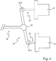
- Figure 4 illustrates the behavior of the arrangement of coupling rod 34 and sum adjusting rod 36 in the event that the adjusting movement of the first linear stepping motor 22 deviates from the adjusting movement of the second linear stepping motor 32.
- first light module-side end 24.2 of the first adjusting rod 24 is rotatably connected to the first end 34.1 of the coupling rod 34 and that the second light-module-side end 38.2 the second control rod 38 is rotatably connected to the second end 34.2 of the coupling rod 34.
- the coupling rod 34 rotates around its second end 34.2 around until the second control rod 38 also begins to extend.
- the coupling rod 34 is supported like a one-sided lever on the second actuating rod 38, which has not yet extended.
- the sum adjusting rod 36 is supported on the pivot bearing 40 of the coupling rod 34 and executes an adjusting movement which is transferred via its two mutually symmetrical branches into a pivoting movement of the two light modules 18, 30 that takes place synchronously and in phase.
- the shape of the light distribution generated jointly by the two advantageously does not change. Only the amplitude of the pivoting movement is somewhat lower than the amplitude that results from a completely synchronous and in-phase movement of the two adjusting rods 24, 38. In particular, it is avoided that the two linear stepping motors 22, 32 interfere with one another.
- Figure 4 illustrates the described case of a discrepancy between the adjusting movements of the two linear stepping motors 22, 32.
- the different adjusting movements lead to an inclined position of the coupling rod 34.
- the angle of inclination is different.
- the angle of inclination results from the amount of deviation of the angle between coupling rod 34 and sum adjusting rod 36 from the value that this angle has with identical adjusting movements of the two linear stepper motors 22, 32 (here: 90 °). This inclination leads to a radial load on the adjusting rods 24, 38 of the linear stepper motors 22, 32.
- one embodiment of the invention provides that the coupling rod 34 has at least one bearing that compensates for changes in length.
- Figure 5 shows an embodiment of such a storage compensating for changes in length for one end 34.2 of the coupling rod 34 and the associated actuating rod 38.
- the other end of the coupling rod and the end of the actuating rod associated with this other end of the coupling rod is preferably configured accordingly (i.e. the same except for necessary deviations).
- the end of the control rod 38.2 has a thickening.
- the associated end 34.2 of the coupling rod is designed as a hollow cylinder with a slot 34.4 running in the axial direction.
- the shape and dimensions of the hollow cylindrical cross section lying transversely to the axial direction are designed as a negative to the outer shape of the thickening with a small amount of play, so that the thickening in the Coupling rod 38 is axially movable.
- the thickenings at the ends 24.2, 38.2 of the actuating rods on the light module side are preferably designed spherically, the part of the actuating rod 24, 38 remaining from the thickening
- Fig. 6 shows an alternative embodiment of a bearing which compensates for changes in length and which has a sliding piece.
- the sliding piece consists of a cylindrical sleeve 48 and pistons 50, 52 protruding into the sleeve, the outer cross-sectional shape and dimensions of which are complementary to the inner cross-sectional shape and the inner dimensions of the sleeve 48.
- Sleeve 48 and piston 50, 52 are therefore axially displaceable relative to one another.
- Sleeve 48 and piston 50, 52 together form an embodiment of a coupling rod 34.
- the rotary bearing 40 with which the sum adjusting rod 36 is coupled to the coupling rod 34, is attached to the sleeve 48.
- One piston 50, 52 is rigidly connected to one of the pivot bearings for the ends of the actuating rod.
- each sleeve is connected to one of the pivot bearings for the control rod ends, and the pivot bearing, with which the sum control rod is coupled to the coupling rod, is attached centrally to a double piston having two ends, one end of which in each case the sleeves protrudes.
- Figure 7 shows an embodiment in which the total adjusting rod 36 is guided by a linear guide 54 which is ultimately rigidly connected to a frame or the housing 12 of the headlight 10 and which allows only axial movements of the total adjusting rod 36.
- This embodiment is advantageously suitable for preventing an undesired inclination of the sum adjusting rod 36, which could otherwise occur as a result of an inclination of the coupling rod 34.
- Figure 8 shows an alternative in which the end of the sum adjusting rod 36 on the light module side is connected to exactly one pivotable light module 18.
- the number n of linear stepping motors 22, 32 can also be greater than two.
- the n linear stepper motors 22, 32 are each individually or in groups of one Stepper motor-specific linear stepper motor driver circuit 56, 58 is controlled. In this case, the linear stepper motor driver circuits must operate synchronously and in phase.
- Each linear stepper motor driver circuit has an output stage switch 56.1, 58.1 and control electronics 56.2, 58.2.
- Figure 10 shows an embodiment in which n with n greater than or equal to 2 linear stepping motors 22, 32 are controlled by only one linear stepping motor driver circuit 56.1, the n linear stepping motors 22, 32 being electrically connected in series.
- Figure 11 shows an embodiment in which n with n greater than or equal to 2 linear stepping motors 22, 32 are controlled by only one linear stepping motor driver circuit, the n linear stepping motors 22, 32 being electrically connected in parallel.
Landscapes
- Engineering & Computer Science (AREA)
- Mechanical Engineering (AREA)
- Lighting Device Outwards From Vehicle And Optical Signal (AREA)
- Non-Portable Lighting Devices Or Systems Thereof (AREA)
Applications Claiming Priority (1)
| Application Number | Priority Date | Filing Date | Title |
|---|---|---|---|
| DE102019122927.8A DE102019122927A1 (de) | 2019-08-27 | 2019-08-27 | Kraftfahrzeugscheinwerfer mit elektromotorisch verstellbarer Abstrahlrichtung |
Publications (2)
| Publication Number | Publication Date |
|---|---|
| EP3785991A1 true EP3785991A1 (fr) | 2021-03-03 |
| EP3785991B1 EP3785991B1 (fr) | 2022-03-23 |
Family
ID=72050766
Family Applications (1)
| Application Number | Title | Priority Date | Filing Date |
|---|---|---|---|
| EP20190759.9A Active EP3785991B1 (fr) | 2019-08-27 | 2020-08-12 | Phare de véhicule automobile dont l'orientation du faisceau est réglable au moyen de moteurs électriques |
Country Status (2)
| Country | Link |
|---|---|
| EP (1) | EP3785991B1 (fr) |
| DE (1) | DE102019122927A1 (fr) |
Cited By (1)
| Publication number | Priority date | Publication date | Assignee | Title |
|---|---|---|---|---|
| CN113083017A (zh) * | 2021-04-07 | 2021-07-09 | 中国科学院近代物理研究所 | 一种用于稳定同位素电磁分离器的收集盒系统 |
Citations (8)
| Publication number | Priority date | Publication date | Assignee | Title |
|---|---|---|---|---|
| EP1260410A1 (fr) * | 2001-05-17 | 2002-11-27 | Saia-Burgess Murten AG | Dispositif d'actionnement et procédé pour ajuster les rayons lumineux émis par un phare |
| EP1270323A1 (fr) * | 2001-06-19 | 2003-01-02 | Saia-Burgess Murten AG | Dispositif d'actionnement pour ajuster les rayons lumineux émis par un phare |
| DE10205215A1 (de) | 2001-12-13 | 2003-10-02 | Automotive Lighting Reutlingen | Vorrichtung und Verfahren zum Verstellen der Lichtaustrittsrichtung eines Kraftfahrzeugscheinwerfers |
| EP1772311A1 (fr) * | 2005-10-06 | 2007-04-11 | Koito Manufacturing Co., Ltd | Projecteur de véhicule |
| FR2956895A1 (fr) * | 2010-02-26 | 2011-09-02 | Peugeot Citroen Automobiles Sa | Dispositif de positionnement isostatique d'un module d'eclairage mobile par rapport a un element fixe |
| FR2981431A1 (fr) * | 2011-10-14 | 2013-04-19 | Aml Systems | Torche d'eclairage pour vehicule automobile |
| US20150009699A1 (en) * | 2013-07-05 | 2015-01-08 | Koito Manufacturing Co., Ltd. | Vehicular headlamp |
| DE102014007865A1 (de) * | 2014-06-03 | 2015-12-03 | Dr. Ing. H.C. F. Porsche Ag | Fahrzeugscheinwerfer |
-
2019
- 2019-08-27 DE DE102019122927.8A patent/DE102019122927A1/de active Pending
-
2020
- 2020-08-12 EP EP20190759.9A patent/EP3785991B1/fr active Active
Patent Citations (8)
| Publication number | Priority date | Publication date | Assignee | Title |
|---|---|---|---|---|
| EP1260410A1 (fr) * | 2001-05-17 | 2002-11-27 | Saia-Burgess Murten AG | Dispositif d'actionnement et procédé pour ajuster les rayons lumineux émis par un phare |
| EP1270323A1 (fr) * | 2001-06-19 | 2003-01-02 | Saia-Burgess Murten AG | Dispositif d'actionnement pour ajuster les rayons lumineux émis par un phare |
| DE10205215A1 (de) | 2001-12-13 | 2003-10-02 | Automotive Lighting Reutlingen | Vorrichtung und Verfahren zum Verstellen der Lichtaustrittsrichtung eines Kraftfahrzeugscheinwerfers |
| EP1772311A1 (fr) * | 2005-10-06 | 2007-04-11 | Koito Manufacturing Co., Ltd | Projecteur de véhicule |
| FR2956895A1 (fr) * | 2010-02-26 | 2011-09-02 | Peugeot Citroen Automobiles Sa | Dispositif de positionnement isostatique d'un module d'eclairage mobile par rapport a un element fixe |
| FR2981431A1 (fr) * | 2011-10-14 | 2013-04-19 | Aml Systems | Torche d'eclairage pour vehicule automobile |
| US20150009699A1 (en) * | 2013-07-05 | 2015-01-08 | Koito Manufacturing Co., Ltd. | Vehicular headlamp |
| DE102014007865A1 (de) * | 2014-06-03 | 2015-12-03 | Dr. Ing. H.C. F. Porsche Ag | Fahrzeugscheinwerfer |
Cited By (1)
| Publication number | Priority date | Publication date | Assignee | Title |
|---|---|---|---|---|
| CN113083017A (zh) * | 2021-04-07 | 2021-07-09 | 中国科学院近代物理研究所 | 一种用于稳定同位素电磁分离器的收集盒系统 |
Also Published As
| Publication number | Publication date |
|---|---|
| DE102019122927A1 (de) | 2021-03-04 |
| EP3785991B1 (fr) | 2022-03-23 |
Similar Documents
| Publication | Publication Date | Title |
|---|---|---|
| DE69103363T2 (de) | Drehbarer Balken um Kameras für stereophotogrammetrische Aufnahmen auf einem Hubschrauber zu montieren. | |
| DE2937961C2 (de) | Vorrichtung zum Verstellen eines Spiegelglasträgers eines Kraftfahrzeugrückspiegels | |
| EP1182485B1 (fr) | Dispositif de réglage de la position relative de deux éléments | |
| EP1848970A1 (fr) | Systeme de pesee | |
| EP2825451B1 (fr) | Dispositif de contrôle de pale de rotor | |
| AT517393B1 (de) | Fahrzeugscheinwerfer mit einstellbaren Baueinheiten | |
| EP0812652A1 (fr) | Dispositif pour usiner et/ou monter des pièces | |
| DE102014000522A1 (de) | Bewegungseinrichtung für einen Flugzeugsitz | |
| DE3804242C2 (fr) | ||
| DE102018122676B4 (de) | Scheinwerfer für Kraftfahrzeuge | |
| DE102014014571A1 (de) | Bedienvorrichtung für ein fahrrad | |
| EP3785991B1 (fr) | Phare de véhicule automobile dont l'orientation du faisceau est réglable au moyen de moteurs électriques | |
| EP3683827A1 (fr) | Cinématique hybride à six étages de liberté et procédure | |
| EP3737585B1 (fr) | Disposif d'éclairage d'un phare de véhicule avec au moins un composant optique et un système de réglage permettant de faire pivoter le composant optique autour d'un premier axe et d'un deuxieme axe | |
| DE102011119946A1 (de) | Stellvorrichtung zum Positionieren eines Bauelements | |
| AT507213B1 (de) | Antriebseinrichtung zum verstellen von zu orientierenden bauteilen eines raumfahrzeugs | |
| EP0112400B1 (fr) | Dispositif d'introduction de forces dans une structure, en particulier un essieu d'une voiture, la suspension de roues etc. | |
| WO2015087260A1 (fr) | Dispositif actionneur pour système de vision arrière d'un véhicule automobile, ainsi que système de vision arrière pour véhicule automobile | |
| EP1848971A1 (fr) | Systeme de pesee | |
| DE102013213254A1 (de) | Betätigungseinheit für ein optisches element mit zweidimensionalem stellantrieb | |
| DE10392396B4 (de) | Interferometer | |
| DE60314424T2 (de) | Mechanismus zum eindeutigen Verbinden einer verschiebbaren und ausrichtbaren Plattform mit einer Tragkonstruktion unter Verwendung von Gelenkarmen | |
| DE102016115267B4 (de) | Vorrichtung zum Einstellen einer Rückenlehnenneigung und Verfahren zur Montage der Vorrichtung | |
| DE19539581B4 (de) | Universalgelenk mit Feder-Viergelenken | |
| DE102022102732B3 (de) | Positioniermodul und Positioniervorrichtung mit einem solchen Positioniermodul |
Legal Events
| Date | Code | Title | Description |
|---|---|---|---|
| PUAI | Public reference made under article 153(3) epc to a published international application that has entered the european phase |
Free format text: ORIGINAL CODE: 0009012 |
|
| STAA | Information on the status of an ep patent application or granted ep patent |
Free format text: STATUS: THE APPLICATION HAS BEEN PUBLISHED |
|
| AK | Designated contracting states |
Kind code of ref document: A1 Designated state(s): AL AT BE BG CH CY CZ DE DK EE ES FI FR GB GR HR HU IE IS IT LI LT LU LV MC MK MT NL NO PL PT RO RS SE SI SK SM TR |
|
| AX | Request for extension of the european patent |
Extension state: BA ME |
|
| STAA | Information on the status of an ep patent application or granted ep patent |
Free format text: STATUS: REQUEST FOR EXAMINATION WAS MADE |
|
| 17P | Request for examination filed |
Effective date: 20210728 |
|
| RBV | Designated contracting states (corrected) |
Designated state(s): AL AT BE BG CH CY CZ DE DK EE ES FI FR GB GR HR HU IE IS IT LI LT LU LV MC MK MT NL NO PL PT RO RS SE SI SK SM TR |
|
| GRAP | Despatch of communication of intention to grant a patent |
Free format text: ORIGINAL CODE: EPIDOSNIGR1 |
|
| STAA | Information on the status of an ep patent application or granted ep patent |
Free format text: STATUS: GRANT OF PATENT IS INTENDED |
|
| INTG | Intention to grant announced |
Effective date: 20211018 |
|
| GRAS | Grant fee paid |
Free format text: ORIGINAL CODE: EPIDOSNIGR3 |
|
| GRAA | (expected) grant |
Free format text: ORIGINAL CODE: 0009210 |
|
| STAA | Information on the status of an ep patent application or granted ep patent |
Free format text: STATUS: THE PATENT HAS BEEN GRANTED |
|
| AK | Designated contracting states |
Kind code of ref document: B1 Designated state(s): AL AT BE BG CH CY CZ DE DK EE ES FI FR GB GR HR HU IE IS IT LI LT LU LV MC MK MT NL NO PL PT RO RS SE SI SK SM TR |
|
| REG | Reference to a national code |
Ref country code: GB Ref legal event code: FG4D Free format text: NOT ENGLISH |
|
| REG | Reference to a national code |
Ref country code: CH Ref legal event code: EP |
|
| REG | Reference to a national code |
Ref country code: DE Ref legal event code: R096 Ref document number: 502020000828 Country of ref document: DE |
|
| REG | Reference to a national code |
Ref country code: IE Ref legal event code: FG4D Free format text: LANGUAGE OF EP DOCUMENT: GERMAN |
|
| REG | Reference to a national code |
Ref country code: AT Ref legal event code: REF Ref document number: 1477225 Country of ref document: AT Kind code of ref document: T Effective date: 20220415 |
|
| REG | Reference to a national code |
Ref country code: LT Ref legal event code: MG9D |
|
| REG | Reference to a national code |
Ref country code: NL Ref legal event code: MP Effective date: 20220323 |
|
| PG25 | Lapsed in a contracting state [announced via postgrant information from national office to epo] |
Ref country code: SE Free format text: LAPSE BECAUSE OF FAILURE TO SUBMIT A TRANSLATION OF THE DESCRIPTION OR TO PAY THE FEE WITHIN THE PRESCRIBED TIME-LIMIT Effective date: 20220323 Ref country code: RS Free format text: LAPSE BECAUSE OF FAILURE TO SUBMIT A TRANSLATION OF THE DESCRIPTION OR TO PAY THE FEE WITHIN THE PRESCRIBED TIME-LIMIT Effective date: 20220323 Ref country code: NO Free format text: LAPSE BECAUSE OF FAILURE TO SUBMIT A TRANSLATION OF THE DESCRIPTION OR TO PAY THE FEE WITHIN THE PRESCRIBED TIME-LIMIT Effective date: 20220623 Ref country code: LT Free format text: LAPSE BECAUSE OF FAILURE TO SUBMIT A TRANSLATION OF THE DESCRIPTION OR TO PAY THE FEE WITHIN THE PRESCRIBED TIME-LIMIT Effective date: 20220323 Ref country code: HR Free format text: LAPSE BECAUSE OF FAILURE TO SUBMIT A TRANSLATION OF THE DESCRIPTION OR TO PAY THE FEE WITHIN THE PRESCRIBED TIME-LIMIT Effective date: 20220323 Ref country code: BG Free format text: LAPSE BECAUSE OF FAILURE TO SUBMIT A TRANSLATION OF THE DESCRIPTION OR TO PAY THE FEE WITHIN THE PRESCRIBED TIME-LIMIT Effective date: 20220623 |
|
| PG25 | Lapsed in a contracting state [announced via postgrant information from national office to epo] |
Ref country code: LV Free format text: LAPSE BECAUSE OF FAILURE TO SUBMIT A TRANSLATION OF THE DESCRIPTION OR TO PAY THE FEE WITHIN THE PRESCRIBED TIME-LIMIT Effective date: 20220323 Ref country code: GR Free format text: LAPSE BECAUSE OF FAILURE TO SUBMIT A TRANSLATION OF THE DESCRIPTION OR TO PAY THE FEE WITHIN THE PRESCRIBED TIME-LIMIT Effective date: 20220624 Ref country code: FI Free format text: LAPSE BECAUSE OF FAILURE TO SUBMIT A TRANSLATION OF THE DESCRIPTION OR TO PAY THE FEE WITHIN THE PRESCRIBED TIME-LIMIT Effective date: 20220323 |
|
| PG25 | Lapsed in a contracting state [announced via postgrant information from national office to epo] |
Ref country code: NL Free format text: LAPSE BECAUSE OF FAILURE TO SUBMIT A TRANSLATION OF THE DESCRIPTION OR TO PAY THE FEE WITHIN THE PRESCRIBED TIME-LIMIT Effective date: 20220323 |
|
| PG25 | Lapsed in a contracting state [announced via postgrant information from national office to epo] |
Ref country code: SM Free format text: LAPSE BECAUSE OF FAILURE TO SUBMIT A TRANSLATION OF THE DESCRIPTION OR TO PAY THE FEE WITHIN THE PRESCRIBED TIME-LIMIT Effective date: 20220323 Ref country code: SK Free format text: LAPSE BECAUSE OF FAILURE TO SUBMIT A TRANSLATION OF THE DESCRIPTION OR TO PAY THE FEE WITHIN THE PRESCRIBED TIME-LIMIT Effective date: 20220323 Ref country code: RO Free format text: LAPSE BECAUSE OF FAILURE TO SUBMIT A TRANSLATION OF THE DESCRIPTION OR TO PAY THE FEE WITHIN THE PRESCRIBED TIME-LIMIT Effective date: 20220323 Ref country code: PT Free format text: LAPSE BECAUSE OF FAILURE TO SUBMIT A TRANSLATION OF THE DESCRIPTION OR TO PAY THE FEE WITHIN THE PRESCRIBED TIME-LIMIT Effective date: 20220725 Ref country code: ES Free format text: LAPSE BECAUSE OF FAILURE TO SUBMIT A TRANSLATION OF THE DESCRIPTION OR TO PAY THE FEE WITHIN THE PRESCRIBED TIME-LIMIT Effective date: 20220323 Ref country code: EE Free format text: LAPSE BECAUSE OF FAILURE TO SUBMIT A TRANSLATION OF THE DESCRIPTION OR TO PAY THE FEE WITHIN THE PRESCRIBED TIME-LIMIT Effective date: 20220323 Ref country code: CZ Free format text: LAPSE BECAUSE OF FAILURE TO SUBMIT A TRANSLATION OF THE DESCRIPTION OR TO PAY THE FEE WITHIN THE PRESCRIBED TIME-LIMIT Effective date: 20220323 |
|
| PG25 | Lapsed in a contracting state [announced via postgrant information from national office to epo] |
Ref country code: PL Free format text: LAPSE BECAUSE OF FAILURE TO SUBMIT A TRANSLATION OF THE DESCRIPTION OR TO PAY THE FEE WITHIN THE PRESCRIBED TIME-LIMIT Effective date: 20220323 Ref country code: IS Free format text: LAPSE BECAUSE OF FAILURE TO SUBMIT A TRANSLATION OF THE DESCRIPTION OR TO PAY THE FEE WITHIN THE PRESCRIBED TIME-LIMIT Effective date: 20220723 Ref country code: AL Free format text: LAPSE BECAUSE OF FAILURE TO SUBMIT A TRANSLATION OF THE DESCRIPTION OR TO PAY THE FEE WITHIN THE PRESCRIBED TIME-LIMIT Effective date: 20220323 |
|
| REG | Reference to a national code |
Ref country code: DE Ref legal event code: R097 Ref document number: 502020000828 Country of ref document: DE |
|
| PLBE | No opposition filed within time limit |
Free format text: ORIGINAL CODE: 0009261 |
|
| STAA | Information on the status of an ep patent application or granted ep patent |
Free format text: STATUS: NO OPPOSITION FILED WITHIN TIME LIMIT |
|
| PG25 | Lapsed in a contracting state [announced via postgrant information from national office to epo] |
Ref country code: DK Free format text: LAPSE BECAUSE OF FAILURE TO SUBMIT A TRANSLATION OF THE DESCRIPTION OR TO PAY THE FEE WITHIN THE PRESCRIBED TIME-LIMIT Effective date: 20220323 |
|
| 26N | No opposition filed |
Effective date: 20230102 |
|
| PG25 | Lapsed in a contracting state [announced via postgrant information from national office to epo] |
Ref country code: MC Free format text: LAPSE BECAUSE OF FAILURE TO SUBMIT A TRANSLATION OF THE DESCRIPTION OR TO PAY THE FEE WITHIN THE PRESCRIBED TIME-LIMIT Effective date: 20220323 |
|
| PG25 | Lapsed in a contracting state [announced via postgrant information from national office to epo] |
Ref country code: LU Free format text: LAPSE BECAUSE OF NON-PAYMENT OF DUE FEES Effective date: 20220812 |
|
| REG | Reference to a national code |
Ref country code: BE Ref legal event code: MM Effective date: 20220831 |
|
| PG25 | Lapsed in a contracting state [announced via postgrant information from national office to epo] |
Ref country code: SI Free format text: LAPSE BECAUSE OF FAILURE TO SUBMIT A TRANSLATION OF THE DESCRIPTION OR TO PAY THE FEE WITHIN THE PRESCRIBED TIME-LIMIT Effective date: 20220323 |
|
| P01 | Opt-out of the competence of the unified patent court (upc) registered |
Effective date: 20230508 |
|
| PG25 | Lapsed in a contracting state [announced via postgrant information from national office to epo] |
Ref country code: IT Free format text: LAPSE BECAUSE OF FAILURE TO SUBMIT A TRANSLATION OF THE DESCRIPTION OR TO PAY THE FEE WITHIN THE PRESCRIBED TIME-LIMIT Effective date: 20220323 Ref country code: IE Free format text: LAPSE BECAUSE OF NON-PAYMENT OF DUE FEES Effective date: 20220812 |
|
| PG25 | Lapsed in a contracting state [announced via postgrant information from national office to epo] |
Ref country code: BE Free format text: LAPSE BECAUSE OF NON-PAYMENT OF DUE FEES Effective date: 20220831 |
|
| PGFP | Annual fee paid to national office [announced via postgrant information from national office to epo] |
Ref country code: FR Payment date: 20230720 Year of fee payment: 4 Ref country code: DE Payment date: 20230720 Year of fee payment: 4 |
|
| REG | Reference to a national code |
Ref country code: CH Ref legal event code: PL |
|
| PG25 | Lapsed in a contracting state [announced via postgrant information from national office to epo] |
Ref country code: CY Free format text: LAPSE BECAUSE OF FAILURE TO SUBMIT A TRANSLATION OF THE DESCRIPTION OR TO PAY THE FEE WITHIN THE PRESCRIBED TIME-LIMIT Effective date: 20220323 Ref country code: CH Free format text: LAPSE BECAUSE OF NON-PAYMENT OF DUE FEES Effective date: 20230831 |
|
| PG25 | Lapsed in a contracting state [announced via postgrant information from national office to epo] |
Ref country code: MK Free format text: LAPSE BECAUSE OF FAILURE TO SUBMIT A TRANSLATION OF THE DESCRIPTION OR TO PAY THE FEE WITHIN THE PRESCRIBED TIME-LIMIT Effective date: 20220323 Ref country code: HU Free format text: LAPSE BECAUSE OF FAILURE TO SUBMIT A TRANSLATION OF THE DESCRIPTION OR TO PAY THE FEE WITHIN THE PRESCRIBED TIME-LIMIT; INVALID AB INITIO Effective date: 20200812 |