EP3785937A1 - Fahrzeugluftreifen - Google Patents
Fahrzeugluftreifen Download PDFInfo
- Publication number
- EP3785937A1 EP3785937A1 EP20189486.2A EP20189486A EP3785937A1 EP 3785937 A1 EP3785937 A1 EP 3785937A1 EP 20189486 A EP20189486 A EP 20189486A EP 3785937 A1 EP3785937 A1 EP 3785937A1
- Authority
- EP
- European Patent Office
- Prior art keywords
- circumferential groove
- groove
- circumferential
- tread
- pneumatic vehicle
- Prior art date
- Legal status (The legal status is an assumption and is not a legal conclusion. Google has not performed a legal analysis and makes no representation as to the accuracy of the status listed.)
- Granted
Links
Images

Classifications
-
- B—PERFORMING OPERATIONS; TRANSPORTING
- B60—VEHICLES IN GENERAL
- B60C—VEHICLE TYRES; TYRE INFLATION; TYRE CHANGING; CONNECTING VALVES TO INFLATABLE ELASTIC BODIES IN GENERAL; DEVICES OR ARRANGEMENTS RELATED TO TYRES
- B60C11/00—Tyre tread bands; Tread patterns; Anti-skid inserts
- B60C11/03—Tread patterns
-
- B—PERFORMING OPERATIONS; TRANSPORTING
- B60—VEHICLES IN GENERAL
- B60C—VEHICLE TYRES; TYRE INFLATION; TYRE CHANGING; CONNECTING VALVES TO INFLATABLE ELASTIC BODIES IN GENERAL; DEVICES OR ARRANGEMENTS RELATED TO TYRES
- B60C11/00—Tyre tread bands; Tread patterns; Anti-skid inserts
- B60C11/03—Tread patterns
- B60C11/0327—Tread patterns characterised by special properties of the tread pattern
- B60C11/033—Tread patterns characterised by special properties of the tread pattern by the void or net-to-gross ratios of the patterns
-
- B—PERFORMING OPERATIONS; TRANSPORTING
- B60—VEHICLES IN GENERAL
- B60C—VEHICLE TYRES; TYRE INFLATION; TYRE CHANGING; CONNECTING VALVES TO INFLATABLE ELASTIC BODIES IN GENERAL; DEVICES OR ARRANGEMENTS RELATED TO TYRES
- B60C11/00—Tyre tread bands; Tread patterns; Anti-skid inserts
- B60C11/03—Tread patterns
- B60C11/0302—Tread patterns directional pattern, i.e. with main rolling direction
-
- B—PERFORMING OPERATIONS; TRANSPORTING
- B60—VEHICLES IN GENERAL
- B60C—VEHICLE TYRES; TYRE INFLATION; TYRE CHANGING; CONNECTING VALVES TO INFLATABLE ELASTIC BODIES IN GENERAL; DEVICES OR ARRANGEMENTS RELATED TO TYRES
- B60C11/00—Tyre tread bands; Tread patterns; Anti-skid inserts
- B60C11/03—Tread patterns
- B60C2011/0337—Tread patterns characterised by particular design features of the pattern
- B60C2011/0339—Grooves
- B60C2011/0341—Circumferential grooves
- B60C2011/0346—Circumferential grooves with zigzag shape
-
- B—PERFORMING OPERATIONS; TRANSPORTING
- B60—VEHICLES IN GENERAL
- B60C—VEHICLE TYRES; TYRE INFLATION; TYRE CHANGING; CONNECTING VALVES TO INFLATABLE ELASTIC BODIES IN GENERAL; DEVICES OR ARRANGEMENTS RELATED TO TYRES
- B60C11/00—Tyre tread bands; Tread patterns; Anti-skid inserts
- B60C11/03—Tread patterns
- B60C2011/0337—Tread patterns characterised by particular design features of the pattern
- B60C2011/0339—Grooves
- B60C2011/0341—Circumferential grooves
- B60C2011/0353—Circumferential grooves characterised by width
-
- B—PERFORMING OPERATIONS; TRANSPORTING
- B60—VEHICLES IN GENERAL
- B60C—VEHICLE TYRES; TYRE INFLATION; TYRE CHANGING; CONNECTING VALVES TO INFLATABLE ELASTIC BODIES IN GENERAL; DEVICES OR ARRANGEMENTS RELATED TO TYRES
- B60C11/00—Tyre tread bands; Tread patterns; Anti-skid inserts
- B60C11/03—Tread patterns
- B60C2011/0337—Tread patterns characterised by particular design features of the pattern
- B60C2011/0339—Grooves
- B60C2011/0358—Lateral grooves, i.e. having an angle of 45 to 90 degees to the equatorial plane
-
- B—PERFORMING OPERATIONS; TRANSPORTING
- B60—VEHICLES IN GENERAL
- B60C—VEHICLE TYRES; TYRE INFLATION; TYRE CHANGING; CONNECTING VALVES TO INFLATABLE ELASTIC BODIES IN GENERAL; DEVICES OR ARRANGEMENTS RELATED TO TYRES
- B60C11/00—Tyre tread bands; Tread patterns; Anti-skid inserts
- B60C11/03—Tread patterns
- B60C2011/0337—Tread patterns characterised by particular design features of the pattern
- B60C2011/0339—Grooves
- B60C2011/0358—Lateral grooves, i.e. having an angle of 45 to 90 degees to the equatorial plane
- B60C2011/0372—Lateral grooves, i.e. having an angle of 45 to 90 degees to the equatorial plane with particular inclination angles
Definitions
- the invention relates to a pneumatic vehicle tire with a tread with at least one circumferential groove running in a zigzag shape in a central tread area and in plan view from groove sections enclosing obtuse angles, at the mutual connection areas of which the circumferential groove each has a groove bend with a bend outside and a bend inside, wherein on at least one side of the circumferential groove parallel to one another, each opening into the circumferential groove on an outside bend are formed.
- Such pneumatic vehicle tires are for example from DE 10 2015 224 290 A1 and the DE 10 2016 217 970 A1 known.
- a pneumatic vehicle tire is disclosed with a tread with oblique grooves running in a V-shape over the width of the tread, which give the tread an "arrow-shaped" profile.
- the oblique grooves extend beyond the tire equatorial plane, run over the majority of their extent to the circumferential direction at an angle of at most 60 ° and have groove sections in the area of shoulder block rows at an angle of 70 ° to 90 ° to the circumferential direction.
- the inclined grooves running in one tread half are offset in the circumferential direction from the inclined grooves running in the other tread half, the inclined grooves merging near the tire equatorial plane and thus forming a zigzag-shaped, central circumferential groove over their end sections running in this area.
- the one from the DE 10 2015 224 290 A1 In known tires, the end sections of the oblique grooves run, for example, at an angle of approximately 35 °.
- the invention is therefore based on the object in a pneumatic vehicle tire of the type mentioned at the outset to improve the water drainage behavior while maintaining good snow grip properties.
- the object set is achieved according to the invention by that the groove sections of the zigzag-shaped circumferential groove run at an angle of 3 ° to 15 ° to the circumferential direction, the inclined grooves - determined at their junctions located on the bend outer sides of the circumferential groove - run to the circumferential direction at an angle which is 20 ° to 45 ° is greater than the angle of the groove sections of the circumferential groove.
- the groove structure according to the invention is therefore formed by groove sections inclined at a relatively small angle to the circumferential direction, forming the zigzag running circumferential groove, and oblique grooves running at an angle to these.
- the zigzag-shaped circumferential groove is thus approximated to a straight circumferential groove, which, compared to tread profiles with exclusively V-shaped inclined grooves over the width of the tread, allows water to "pass" effectively in the circumferential direction through the ground contact area when passing through the ground contact area.
- partial flows of water are diverted from the circumferential groove into the inclined grooves and thus in the direction of the lateral edge of the ground contact area, which prevents the zigzag circumferential groove from "overflowing".
- the pneumatic vehicle tire according to the invention therefore provides an optimal compromise between good snow reef properties and good behavior when there is a risk of aquaplaning.
- the inclined grooves cooperate particularly advantageously in the manner described with the circumferential groove when the angle at which the inclined grooves - determined at their junctions located on the circumferential groove - run to the circumferential direction by 25 ° to 40 °, in particular from 30 ° to 38 ° , preferably by at least 32 °, is greater than the angle of the groove sections of the circumferential groove relative to the circumferential direction.
- the circumferential groove (s) has a width which is 1.5% to 3.5% of the width of the ground contact area of the tread according to E.T.R.T.O. standards.
- the central tread area in which the circumferential groove (s) runs or run, has a width in the axial direction of 15% to 25%, in particular 15% to 20%, of the width of the ground contact area of the Has tread.
- the circumferential groove (s) and the inclined grooves in the central tread area determined at the tread periphery, have a negative area of 20% to 30%, in particular 22% to 28%, of the total area of the have central tread area.
- an inclined groove opens out on each side of the circumferential groove on each or every second bend outer side.
- the tread has two circumferential grooves running next to one another and in a zigzag shape in plan view, the oblique grooves opening into the circumferential grooves on the sides of the circumferential grooves facing away from one another at the bend outer sides.
- two groups of inclined grooves running parallel to one another and opening into the circumferential groove (s) are provided, the inclined grooves of one group being inclined in opposite directions to the inclined grooves of the other group with respect to the circumferential direction.
- Such directional profiles with "arrow-shaped" profiling are particularly favorable for the water drainage capacity.
- the or each circumferential groove is designed in such a way that, viewed in the cross section aligned in the axial direction through the respective circumferential groove or the respective circumferential groove, no "look through” is possible through the respective circumferential groove or the respective circumferential groove.
- Pneumatic vehicle tires designed according to the invention are, in particular, tires of radial construction for passenger cars, vans or light trucks, the tires being intended for driving under winter driving conditions.
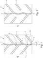
- FIGS. 1 to 3 each show a central section of a tread of a pneumatic vehicle tire.
- the equatorial plane of the tire is indicated in each case by a dashed line AA.
- the tread has, as will be explained in more detail, a directional profiling and is to be mounted on the vehicle in such a way that it has the rolling direction indicated in the figures by the arrow R when driving forward.
- the tread has a central circumferential groove 1 running in a zigzag shape in the area of the tire equatorial plane (line AA) and in plan view, which is designed to the tread depth of usually 6.5 mm to 10.0 mm provided and on the tread periphery has a particularly constant width b 1 of 3.0 mm to 6.0 mm, preferably of up to 5.0 mm, determined transversely to the course of the groove.
- the width b 1 of the central circumferential groove 1 is also in particular 1.5% to 3.5% of the width of the ground contact area of the tread determined in the axial direction, the ground contact area being the statically determined footprint according to ETRTO standards (load at 70% of the maximum load capacity at an internal pressure of 85% according to the ETRTO standard).
- the middle circumferential groove 1 is composed of straight groove sections 1a enclosing obtuse angles with one another, which are oriented to the circumferential direction at an angle ⁇ of 3 ° to 15 °, in particular of up to 12 °, particularly preferably of up to 10 ° , wherein immediately successive groove sections 1a - corresponding to the zigzag shape - are inclined in opposite directions with respect to the circumferential direction.
- the size of the angle ⁇ can - due to the so-called pitch sequence of the tread profile - vary in particular by up to 6 °.
- the central circumferential groove 1 extends in the region of the tire equatorial plane in such a way that each groove section 1a intersects the tire equatorial plane.
- the circumferential groove 1 On mutual In the connection area of the groove sections 1a, the circumferential groove 1 each has a groove kink with an outside kink 1 'and an inside kink 1 ".
- the width b 1 and the angle ⁇ are matched to one another in such a way that, viewed in the cross-section through the circumferential groove 1 oriented in the axial direction, no view through the circumferential groove 1 is possible (no "look-through").
- the circumferential groove 1 separates two profile ribs 2 running side by side, which have triangular rib sections 2a projecting on the circumferential groove 1 in plan view, which are each delimited by two immediately successive groove sections 1a and at the mutual connection area of the groove sections 1a, on the bend insides 1 ′′ of the circumferential groove 1
- the profile ribs 2 are each structured in a block-like manner with a number of oblique grooves 3 that run parallel to one another in plan view and in the exemplary embodiment shown, the oblique grooves 3 on the bent outer sides 1 'of the circumferential groove 1, i.e. opposite those of the obtuse-angled corner regions 2a ', open into the circumferential groove 1.
- the inclined grooves 3 running in one profile rib 2 are inclined in opposite directions with respect to the circumferential direction to the inclined grooves 3 running in the respective other profile rib 2 Circumferential direction in each case at an angle ⁇ and form with the groove sections 1a adjoining them on the respective bend outside 1 'in plan view Y-shaped groove intersections 4.
- the angle ⁇ of the oblique grooves 3 is around 20 ° to 45 °, in particular around 25 ° to 40 ° , preferably by 30 ° to 38 °, particularly preferably by at least 32 °, greater than the mentioned angle ⁇ of the groove sections 1 a of the circumferential groove 1.
- the rolling direction of the tire is such that the inclined grooves 3 first enter the ground with their ends on the inside of the tread that lie on the circumferential groove 1.
- Fig. 2 The variant shown differs from that of the Fig. 1 in that in each profile rib 2 every second inclined groove 3 ends at a distance in front of the central circumferential groove 1, so that the profile ribs 2 are formed from double block structures 2b that follow one another in the circumferential direction, in each of which an inclined groove 3 terminates.
- two zigzag-shaped and parallel central circumferential grooves 1 are provided, which extend on different sides of the tire equatorial plane.
- the two circumferential grooves 1 jointly delimit a central profile rib 5 running around the circumference with rib regions 5a, which are triangular in plan view, on each circumferential groove 1, with one tread outside of the circumferential grooves 1 in each case analogous to Fig. 1 designed profile rib 2 connects.
- Inclined grooves 3 run in the profile ribs 2, which open into the respective circumferential groove 1 opposite the triangular rib regions 5a.
- the central circumferential groove (s) 1 therefore runs in a central tread region, i.e., symmetrical with respect to the tire equatorial plane. It is preferred here if the central tread area has a width in the axial direction of 15% to 25%, in particular 15% to 20%, of the width of the ground contact area of the tread. Furthermore, it is preferred if the circumferential groove (s) 1 and the inclined grooves 3 in the new tire in the central tread area, determined at the tread periphery, have a negative area of 20% to 30%, in particular 22% to 28%, of the total area of the central Have tread area at the tread periphery.
- the inclined grooves preferably run up to the respective lateral edge of the tread, can also run slightly curved in plan view and have groove sections that are more inclined to the circumferential direction and run in the area of rows of shoulder blocks.
- the straight or curved oblique grooves run - determined at their confluence lying on the respective circumferential groove - to the circumferential direction at an angle that is 20 ° to 45 ° greater than the groove sections of the circumferential groove. In the case of curved oblique grooves, the angle with respect to a line connecting the ends of the curved center line of the oblique groove is determined.
- All positive profiles of the tread are preferably provided with incisions, in particular made in a manner known per se.
Landscapes
- Engineering & Computer Science (AREA)
- Mechanical Engineering (AREA)
- Tires In General (AREA)
Abstract
Description
- Die Erfindung betrifft einen Fahrzeugluftreifen mit einem Laufstreifen mit zumindest einer in einem zentralen Laufstreifenbereich und in Draufsicht zick-zack-förmig verlaufenden Umfangsrille aus miteinander stumpfe Winkel einschließenden Rillenabschnitten, an deren gegenseitigen Anschlussbereichen die Umfangsrille jeweils einen Rillenknick mit einer Knickaußenseite und einer Knickinnenseite aufweist, wobei an zumindest einer Seite der Umfangsrille parallel zueinander verlaufende, jeweils an einer Knickaußenseite in die Umfangsrille einmündende Schrägrillen ausgebildet sind.
- Derartige Fahrzeugluftreifen sind beispielsweise aus der
DE 10 2015 224 290 A1 und derDE 10 2016 217 970 A1 bekannt. Offenbart ist jeweils ein Fahrzeugluftreifen mit einem Laufstreifen mit V-förmig über die Laufstreifenbreite verlaufenden Schrägrillen, welche dem Laufstreifen ein "gepfeiltes" Profil verleihen. Die Schrägrillen erstrecken sich über die Reifenäquatorialebene hinaus, verlaufen über den Großteil ihrer Erstreckung zur Umfangsrichtung unter einem Winkel von höchstens 60° und weisen im Bereich von Schulterblockreihen unter einem Winkel von 70° bis 90° zur Umfangsrichtung verlaufende Rillenabschnitte auf. Die in der einen Laufstreifenhälfte verlaufenden Schrägrillen sind zu den in der anderen Laufstreifenhälfte verlaufenden Schrägrillen in Umfangsrichtung versetzt, wobei die Schrägrillen nahe der Reifenäquatorialebene ineinander einmünden und derart über ihre in diesem Bereich verlaufenden Endabschnitte eine in Draufsicht zick-zackförmige verlaufende, mittlere Umfangsrille bilden. Bei dem aus derDE 10 2015 224 290 A1 bekannten Reifen verlaufen die Endabschnitte der Schrägrillen beispielsweise unter einem Winkel von etwa 35°. - Die Auswirkungen von zick-zack-förmig verlaufenden Umfangsrillen auf die Schneegriffeigenschaften und das Aquaplaningverhalten des Reifens unterscheiden sich von jenen von gerade verlaufenen Umfangsrillen. In zick-zack-förmig verlaufenden Umfangsrillen kann sich beim Fahren auf schneebedeckter Fahrbahn gut Schnee ansammeln, wodurch, über den Effekt der Schnee-Schnee-Reinigung einerseits, und andererseits auch durch die gewinkelten Rillenkanten die Schneegriffeigenschaften vorteilhaft beinflussbar sind. Im Hinblick auf die Wasserdrainageeigenschaften sind üblicherweise gerade verlaufende Umfangsrillen zick-zack-förmig verlaufenden Umfangsrillen überlegen. Bei Fahrzeugluftreifen der eingangs genannten Art lässt sich Wasser aus den zick-zack-förmig verlaufende Umfangsillen hauptsächlich über die anschließenden Schrägrillen ableiten.
- Der Erfindung liegt daher die Aufgabe zugrunde, bei einem Fahrzeugluftreifen der eingangs genannten Art, das Wasserableitverhalten unter Beibehaltung guter Schneegriffeigenschaften zu verbessern.
- Gelöst wird die gestellte Aufgabe erfindungsgemäß dadurch,
dass die Rillenabschnitte der zick-zack-förmig verlaufenden Umfangsrille zur Umfangsrichtung unter einem Winkel von 3° bis 15° verlaufen, wobei die Schrägrillen - ermittelt an ihren an den Knickaußenseiten der Umfangsrille liegenden Einmündungen - zur Umfangsrichtung unter einem Winkel verlaufen, welcher um 20° bis 45° größer ist als der Winkel der Rillenabschnitte der Umfangsrille. - Die erfindungsgemäße Rillenstruktur ist daher durch unter einem relativ geringen Winkel zur Umfangsrichtung geneigte, die zick-zack-förmig verlaufende Umfangsrille bildende Rillenabschnitte und zu diesen gewinkelt verlaufenden Schrägrillen gebildet. Die zick-zack-förmig verlaufende Umfangsrille ist somit einer gerade verlaufenden Umfangsrille angenähert, wodurch sich gegenüber Laufstreifenprofilen mit ausschließlich V-förmig über die Laufstreifenbreite verlaufenden Schrägrillen beim Durchlaufen der Bodenaufstandsfläche auf wirkungsvolle Weise Wasser in Umfangsrichtung durch die Bodenaufstandsfläche "durchleiten" lässt. Gleichzeitig werden Wasserteilströme aus der Umfangsrille in die Schrägrillen und damit in Richtung zum seitlichen Rand der Bodenaufstandsfläche abgeleitet, wodurch ein "Überlaufen" der zick-zack-förmig verlaufenden Umfangsrille verhindert wird. Weiterhin kann sich beim Fahren auf Schnee in der zick-zack-förmig verlaufenden Umfangsrille angesammelter Schnee sehr gut halten, wodurch gute Schneegriffeigenschaften erhalten bleiben. Der erfindungsgemäße Fahrzeugluftreifen liefert daher einen optimalen Kompromiss zwischen guten Schneeriffeigenschaften und gutem Verhalten bei Gefahr von Aquaplaning.
- Die Schrägrillen wirken besonders vorteilhaft auf die beschriebene Weise mit der Umfangsrille zusammen, wenn der Winkel, unter welchem die Schrägrillen - ermittelt an ihren an der Umfangsrille liegenden Einmündungen - zur Umfangsrichtung verlaufen, um 25° bis 40°, insbesondere von 30° bis 38°, bevorzugt um zumindest 32°, größer ist als der Winkel der Rillenabschnitte der Umfangsrille relativ zur Umfangsrichtung.
- Gemäß einer weiteren bevorzugten, für eine gute Wasserableitung vorteilhaften Ausführung weist bzw. weisen die Umfangsrille(n) eine Breite auf, welche 1,5% bis 3,5% der Breite der Bodenaufstandsfläche des Laufstreifens gemäß E.T.R.T.O.-Standards beträgt.
- Eine weitere bevorzugte Ausführung ist dadurch gekennzeichnet, dass der zentrale Laufstreifenbereich, in welchem die Umfangsrille(n) verläuft bzw. verlaufen, in axialer Richtung eine Breite von 15% bis 25%, insbesondere von 15% bis 20%, der Breite der Bodenaufstandsfläche des Laufstreifens aufweist.
- Für das Wasserableitvermögen des Laufstreifens ist es ferner günstig, wenn die Umfangsrille(n) und die Schrägrillen im zentralen Laufstreifenbereich, ermittelt an der Laufstreifenperipherie, einen flächenmäßigen Negativanteil von 20% bis 30%, insbesondere von 22% bis 28%, an der Gesamtfläche des zentralen Laufstreifenbereiches aufweisen.
- Bei einem Fahrzeugluftreifen mit einem Laufstreifen mit einer einzigen zick-zack-förmig verlaufenden Umfangsrille, welche entlang der Reifenäquatorialebene verläuft, ist es für das Wasserableitvermögen und gute Schneegriffeigenschaften ferner besonders vorteilhaft, wenn an beiden Seiten der Umfangsrille an Knickaußenseiten Schrägrillen einmünden.
- Gemäß einer bevorzugten Variante dieser Ausführung mündet an jeder Seite der Umfangsrille an jeder oder an jeder zweiten Knickaußenseite jeweils eine Schrägrille ein.
- Gemäß einer weiteren bevorzugten Ausführung weist der Laufstreifen zwei nebeneinander und in Draufsicht zick-zack-förmig verlaufende Umfangsrillen auf, wobei die Schrägrillen an den einander abgewandten Seiten der Umfangsrillen an Knickaußenseiten in diese einmünden.
- Gemäß einer weiteren bevorzugten Ausführung sind zwei Gruppen von jeweils parallel zueinander verlaufenden, in die Umfangsrille(n) einmündenden Schrägrillen vorgesehen, wobei die Schrägrillen der einen Gruppe zu den Schrägrillen der anderen Gruppe bezüglich der Umfangsrichtung gegensinnig geneigt sind. Solche direktionalen Profile mit "gepfeilter" Profilierung sind vor allem für das Wasserableitvermögen besonders günstig.
- Ferner ist es bevorzugt, wenn die bzw. jede Umfangsrille derart ausgeführt ist, dass, im in axialer Richtung ausgerichteten Querschnitt durch die bzw. die jeweilige Umfangsrille betrachtet, keine Durchsicht ("look through") durch die bzw. die jeweilige Umfangsrille möglich ist.
- Weitere Merkmale, Vorteile und Einzelheiten der Erfindung werden nun anhand der Zeichnung, die schematisch Ausführungsbeispiele der Erfindung zeigt, näher beschrieben. Dabei zeigen
-
Fig. 1 eine Draufsicht auf einen Ausschnitt eines Laufstreifens eines Fahrzeugluftreifens mit einer ersten Ausführungsvariante der Erfindung, -
Fig. 2 eine Draufsicht auf einen Ausschnitt eines Laufstreifens eines Fahrzeugluftreifens mit einer zweiten Ausführungsvariante der Erfindung und -
Fig. 3 eine Draufsicht auf einen Ausschnitt eines Laufstreifens eines Fahrzeugluftreifens mit einer dritten Ausführungsvariante der Erfindung. - Gemäß der Erfindung ausgeführte Fahrzeugluftreifen sind insbesondere Reifen in Radialbauart für Personenkraftwagen, Vans oder Light-Trucks, wobei die Reifen zum Fahren unter winterlichen Fahrbedingungen vorgesehen sind.
-
Fig. 1 bis Fig. 3 zeigen jeweils einen zentralen Ausschnitt eines Laufstreifens eines Fahrzeugluftreifens. Die Äquatorialebene des Reifens ist jeweils durch eine gestrichelte Linie A-A angedeutet. Der Laufstreifen weist bei den gezeigten Ausführungsbeispielen, wie noch genauer erläutert wird, eine laufrichtungsgebundene Profilierung auf und ist derart am Fahrzeug zu montieren, dass er die in den Figuren durch den Pfeil R angedeutete Abrollrichtung bei Vorwärtsfahrt aufweist. - Bei der in
Fig. 1 gezeigten Variante weist der Laufstreifen eine im Bereich der Reifenäquatorialebene (Linie A-A) sowie in Draufsicht zickzack-förmig verlaufende, mittlere Umfangsrille 1 auf, welche auf die jeweils vorgesehene Profiltiefe von üblicherweise 6,5 mm bis 10,0 mm ausgeführt ist und an der Laufstreifenperipherie eine quer zum Rillenverlauf ermittelte, insbesondere konstante Breite b1 von 3,0 mm bis 6,0 mm, vorzugsweise von bis zu 5,0 mm, aufweist. Die Breite b1 der mittleren Umfangsrille 1 beträgt ferner insbesondere 1,5% bis 3,5% der in axialer Richtung ermittelten Breite der Bodenaufstandsfläche des Laufstreifens, wobei die Bodenaufstandsfläche dem statisch ermittelten Footprint gemäß E.T.R.T.O.-Standards (Last bei 70% der maximalen Tragfähigkeit bei einem Innendruck von 85% nach E.T.R.T.O.-Norm) entspricht. - Die mittlere Umfangsrille 1 setzt sich aus miteinander stumpfe Winkel einschließenden, gerade verlaufenden Rillenabschnitten 1a zusammen, welche zur Umfangsrichtung jeweils unter einem Winkel α von 3° bis 15°, insbesondere von bis zu 12°, besonderes bevorzugt von bis zu 10°, orientiert sind, wobei unmittelbar aufeinanderfolgende Rillenabschnitte 1a - entsprechend der Zickzack-Form - bezüglich der Umfangsrichtung gegensinnig zueinander geneigt sind. Die Größe des Winkels α kann - bedingt durch die sogenannte Pitchfolge des Laufstreifenprofils - um insbesondere bis zu 6° variieren. Die mittlere Umfangsrille 1 erstreckt sich dabei derart im Bereich der Reifenäquatorialebene, dass jeder Rillenabschnitt 1a die Reifenäquatorialebene schneidet. Am gegenseitigen Anschlussbereich der Rillenabschnitte 1a weist die Umfangsrille 1 jeweils einen Rillenknick mit einer Knickaußenseite 1' und einer Knickinnenseite 1" auf. Die Breite b1 und der Winkel α sind derart aufeinander abgestimmt, dass, im in axialer Richtung ausgerichteten Querschnitt durch die Umfangsrille 1 betrachtet, keine Durchsicht durch die Umfangsrille 1 möglich ist (kein "look-through").
- Die Umfangsrille 1 trennt zwei nebeneinander verlaufende Profilrippen 2, welche an der Umfangsrille 1 in Draufsicht vorspringende, dreieckförmige Rippenabschnitte 2a aufweisen, die jeweils von zwei unmittelbar aufeinanderfolgenden Rillenabschnitten 1a begrenzt sind und am gegenseitigen Anschlussbereich der Rillenabschnitte 1a, an den Knickinnenseiten 1" der Umfangsrille 1 einen stumpfwinkeligen Eckbereich 2a' aufweisen. Die Profilrippen 2 sind jeweils mit einer Anzahl von in Draufsicht parallel zueinander sowie beim gezeigten Ausführungsbeispiel gerade verlaufenden Schrägrillen 3 blockartig strukturiert, wobei die Schrägrillen 3 an den Knickaußenseiten 1' der Umfangsrille 1, also gegenüber den der stumpfwinkeligen Eckbereiche 2a', in die Umfangsrille 1 einmünden. Ferner sind die in der einen Profilrippe 2 verlaufenden Schrägrillen 3 zu den in der jeweils anderen Profilrippe 2 verlaufenden Schrägrillen 3 bezüglich der Umfangsrichtung gegensinnig geneigt. Die Schrägrillen 3 verlaufen zur Umfangsrichtung jeweils unter einem Winkel β und bilden mit den an der jeweiligen Knickaußenseite 1' an sie anschließenden Rillenabschnitten 1a in Draufsicht Y-förmige Rillenkreuzungen 4. Der Winkel β der Schrägrillen 3 ist um 20° bis 45°, insbesondere um 25° bis 40°, bevorzugt um 30° bis 38°, besonders bevorzugt um zumindest 32°, größer als der erwähnte Winkel α der Rillenabschnitte 1a der Umfangsrille 1.
- Die Abrollrichtung des Reifens ist derart, dass die Schrägrillen 3 mit ihren an der Umfangsrille 1 liegenden, laufstreifeninnenseitigen Enden zuerst in den Untergrund eintreten.
- Die in
Fig. 2 gezeigte Variante unterscheidet sich von jener derFig. 1 dadurch, dass in jeder Profilrippe 2 jede zweite Schrägrille 3 in einem Abstand vor der mittleren Umfangsrille 1 endet, sodass die Profilrippen 2 aus in Umfangsrichtung aufeinanderfolgenden Doppelblockstrukturen 2b gebildet sind, in welchen jeweils eine Schrägrille 3 ausläuft. - Bei der in
Fig. 3 gezeigten Variante sind zwei zick-zack-förmig sowie parallel zueinander verlaufende mittlere Umfangsrillen 1 vorgesehen, welche sich an unterschiedlichen Seiten der Reifenäquatorialebene erstrecken. Die beiden Umfangsrillen 1 begrenzen gemeinsam eine in Umfangsrichtung umlaufende, zentrale Profilrippe 5 mit in Draufsicht dreieckförmigen Rippenbereichen 5a an jeder Umfangsrille 1, wobei laufstreifenaußenseitig der Umfangsrillen 1 jeweils eine analog zuFig. 1 gestaltete Profilrippe 2 anschließt. In den Profilrippen 2 verlaufen Schrägrillen 3, welche gegenüber den dreieckförmigen Rippenbereichen 5a in die jeweilige Umfangsrille 1 einmünden. - Bei sämtlichen Ausführungsvarianten verläuft bzw. verlaufen die mittlere(n) Umfangsrille(n) 1 daher in einem zentralen, d.h. bezüglich der Reifenäquatorialebene symmetrischen, Laufstreifenbereich. Es ist dabei bevorzugt, wenn der zentrale Laufstreifenbereich in axialer Richtung eine Breite von 15% bis 25%, insbesondere von 15% bis 20%, der Breite der Bodenaufstandsfläche des Laufstreifens aufweist. Ferner ist es bevorzugt, wenn die Umfangsrille(n) 1 und die Schrägrillen 3 bei neuem Reifen im zentralen Laufstreifenbereich, ermittelt an der Laufstreifenperipherie, einen flächenmäßigen Negativanteil von 20% bis 30%, insbesondere von 22% bis 28%, der Gesamtfläche des zentralen Laufstreifenbereiches an der Laufstreifenperipherie aufweisen.
- Die Erfindung ist auf die beschriebenen Ausführungsvarianten nicht beschränkt.
- Die Schrägrillen verlaufen vorzugsweise bis zum jeweiligen seitlichen Rand des Laufstreifens, können in Draufsicht auch leicht gebogen verlaufen sowie zur Umfangsrichtung stärker geneigte, im Bereich von Schulterblockreihen verlaufende Rillenabschnitte aufweisen. Die geraden bzw. gebogenen Schrägrillen verlaufen - ermittelt an ihrer an der bzw. der jeweiligen Umfangsrille liegenden Einmündung - zur Umfangsrichtung unter einem um 20° bis 45° größeren Winkel als die Rillenabschnitte der Umfangsrille. Bei gebogenen Schrägrillen ist der Winkel gegenüber einer die Enden der gebogenen Mittellinie der Schrägrille verbindenden Linie ermittelt.
- Bevorzugter Weise sind sämtliche Profilpositive des Laufstreifens mit insbesondere in an sich bekannter Weise ausgeführten Einschnitten versehen.
-
- 1 ......................
- mittlere Umfangsrille
- 1a ....................
- Rillenabschnitt
- 1' .....................
- Knickaußenseite
- 1" ....................
- Knickinnenseite
- 2 ......................
- Profilrippe
- 2a ....................
- Rippenabschnitt
- 2a' ...................
- Eckbereich
- 2b ....................
- Doppelblockstruktur
- 3 ......................
- Schrägrille
- 4 ......................
- Rillenkreuzung
- 5 ......................
- zentrale Profilrippe
- 5a ....................
- Rippenbereich
- A-A .................
- Linie (Äquatorialebene)
- b1 .....................
- Breite
- R .....................
- Pfeil (Abrollrichtung)
- α, β ..................
- Winkel
Claims (10)
- Fahrzeugluftreifen mit einem Laufstreifen mit zumindest einer in einem zentralen Laufstreifenbereich und in Draufsicht zick-zack-förmig verlaufenden Umfangsrille (1) aus miteinander stumpfe Winkel einschließenden Rillenabschnitten (1a), an deren gegenseitigen Anschlussbereichen die Umfangsrille (1) jeweils einen Rillenknick mit einer Knickaußenseite (1') und einer Knickinnenseite (1") aufweist, wobei an zumindest einer Seite der Umfangsrille (1) parallel zueinander verlaufende, jeweils an einer Knickaußenseite (1') in die Umfangsrille (1) einmündende Schrägrillen (3) ausgebildet sind,
dadurch gekennzeichnet,
dass die Rillenabschnitte (1a) der zick-zack-förmig verlaufenden Umfangsrille (1) zur Umfangsrichtung unter einem Winkel (α) von 3° bis 15° verlaufen, wobei die Schrägrillen (3) - ermittelt an ihren an den Knickaußenseiten (1') der Umfangsrille (1) liegenden Einmündungen - zur Umfangsrichtung unter einem Winkel (β) verlaufen, welcher um 20° bis 45° größer ist als der Winkel (α) der Rillenabschnitte (1a) der Umfangsrille (1). - Fahrzeugluftreifen nach Anspruch 1, dadurch gekennzeichnet, dass der Winkel (β), unter welchem die Schrägrillen (3) - ermittelt an ihren an der Umfangsrille (1) liegenden Einmündungen - zur Umfangsrichtung verlaufen, um 25° bis 40°, insbesondere von 30° bis 38°, bevorzugt um zumindest 32°, größer ist als der Winkel der Rillenabschnitte (1a) der Umfangsrille (1) relativ zur Umfangsrichtung.
- Fahrzeugluftreifen nach Anspruch 1 oder 2, dadurch gekennzeichnet, dass die Umfangsrille(n) (1) eine Breite (b1) aufweist bzw. aufweisen, welche 1,5% bis 3,5% der Breite der Bodenaufstandsfläche des Laufstreifens gemäß E.T.R.T.O.-Standards beträgt.
- Fahrzeugluftreifen nach einem der Ansprüche 1 bis 3, dadurch gekennzeichnet, dass der zentrale Laufstreifenbereich, in welchem die Umfangsrille(n) (1) verläuft bzw. verlaufen, in axialer Richtung eine Breite von 15% bis 25%, insbesondere von 15% bis 20%, der Breite der Bodenaufstandsfläche des Laufstreifens aufweist.
- Fahrzeugluftreifen nach einem der Ansprüche 1 bis 4, dadurch gekennzeichnet, dass die Umfangsrille(n) (1) und die Schrägrillen (3) im zentralen Laufstreifenbereich, ermittelt an der Laufstreifenperipherie, einen flächenmäßigen Negativanteil von 20% bis 30%, insbesondere von 22% bis 28%, an der Gesamtfläche des zentralen Laufstreifenbereiches an der Laufstreifenperipherie aufweisen.
- Fahrzeugluftreifen mit einem Laufstreifen mit einer einzigen zick-zack-förmig verlaufenden Umfangsrille (1), welche entlang der Reifenäquatorialebene (A-A) verläuft, nach einem der Ansprüche 1 bis 5, dadurch gekennzeichnet, dass an beiden Seiten der Umfangsrille (1) an Knickaußenseiten (1') Schrägrillen (3) einmünden.
- Fahrzeugluftreifen nach Anspruch 6, dadurch gekennzeichnet, dass an jeder Seite der Umfangsrille (1) an jeder oder an jeder zweiten Knickaußenseite (1') jeweils eine Schrägrille (3) einmündet.
- Fahrzeugluftreifen nach einem der Ansprüche 1 bis 5, dadurch gekennzeichnet, dass der Laufstreifen zwei nebeneinander und in Draufsicht zick-zack-förmig verlaufende Umfangsrillen (1) aufweist, wobei die Schrägrillen (3) an den einander abgewandten Seiten der Umfangsrillen (1) an Knickaußenseiten (1') in diese einmünden.
- Fahrzeugluftreifen nach einem der Ansprüche 1 bis 8, dadurch gekennzeichnet, dass zwei Gruppen von jeweils parallel zueinander verlaufenden, in die Umfangsrille(n) (1) einmündenden Schrägrillen (3) vorgesehen sind, wobei die Schrägrillen (3) der einen Gruppe zu den Schrägrillen (3) der anderen Gruppe bezüglich der Umfangsrichtung gegensinnig geneigt sind.
- Fahrzeugluftreifen nach einem der Ansprüche 1 bis 9, dadurch gekennzeichnet, dass die bzw. jede Umfangsrille (1) derart ausgeführt ist, dass im in axialer Richtung ausgerichteten Querschnitt durch die bzw. die jeweilige Umfangsrille (1) betrachtet, keine Durchsicht durch die bzw. die jeweilige Umfangsrille (1) gegeben ist.
Applications Claiming Priority (1)
| Application Number | Priority Date | Filing Date | Title |
|---|---|---|---|
| DE102019213038.0A DE102019213038A1 (de) | 2019-08-29 | 2019-08-29 | Fahrzeugluftreifen |
Publications (2)
| Publication Number | Publication Date |
|---|---|
| EP3785937A1 true EP3785937A1 (de) | 2021-03-03 |
| EP3785937B1 EP3785937B1 (de) | 2022-10-12 |
Family
ID=71950436
Family Applications (1)
| Application Number | Title | Priority Date | Filing Date |
|---|---|---|---|
| EP20189486.2A Active EP3785937B1 (de) | 2019-08-29 | 2020-08-04 | Fahrzeugluftreifen |
Country Status (2)
| Country | Link |
|---|---|
| EP (1) | EP3785937B1 (de) |
| DE (1) | DE102019213038A1 (de) |
Citations (6)
| Publication number | Priority date | Publication date | Assignee | Title |
|---|---|---|---|---|
| US20090044890A1 (en) * | 2004-11-18 | 2009-02-19 | Shingo Takahashi | Heavy duty pneumatic tire |
| EP2332746A2 (de) * | 2009-12-08 | 2011-06-15 | Sumitomo Rubber Industries, Ltd. | Motorradreifen |
| EP2418101A1 (de) * | 2010-08-10 | 2012-02-15 | Sumitomo Rubber Industries, Ltd. | Schwerlastreifen |
| EP2952362A1 (de) * | 2014-06-04 | 2015-12-09 | Sumitomo Rubber Industries, Ltd. | Luftreifen |
| EP2990229A1 (de) * | 2014-08-26 | 2016-03-02 | Sumitomo Rubber Industries Limited | Scherlastluftreifen |
| EP3015290A1 (de) * | 2013-07-12 | 2016-05-04 | Sumitomo Rubber Industries, Ltd. | Luftreifen |
Family Cites Families (1)
| Publication number | Priority date | Publication date | Assignee | Title |
|---|---|---|---|---|
| JP6378634B2 (ja) * | 2015-02-10 | 2018-08-22 | 住友ゴム工業株式会社 | 自動二輪車用タイヤ |
-
2019
- 2019-08-29 DE DE102019213038.0A patent/DE102019213038A1/de not_active Withdrawn
-
2020
- 2020-08-04 EP EP20189486.2A patent/EP3785937B1/de active Active
Patent Citations (6)
| Publication number | Priority date | Publication date | Assignee | Title |
|---|---|---|---|---|
| US20090044890A1 (en) * | 2004-11-18 | 2009-02-19 | Shingo Takahashi | Heavy duty pneumatic tire |
| EP2332746A2 (de) * | 2009-12-08 | 2011-06-15 | Sumitomo Rubber Industries, Ltd. | Motorradreifen |
| EP2418101A1 (de) * | 2010-08-10 | 2012-02-15 | Sumitomo Rubber Industries, Ltd. | Schwerlastreifen |
| EP3015290A1 (de) * | 2013-07-12 | 2016-05-04 | Sumitomo Rubber Industries, Ltd. | Luftreifen |
| EP2952362A1 (de) * | 2014-06-04 | 2015-12-09 | Sumitomo Rubber Industries, Ltd. | Luftreifen |
| EP2990229A1 (de) * | 2014-08-26 | 2016-03-02 | Sumitomo Rubber Industries Limited | Scherlastluftreifen |
Also Published As
| Publication number | Publication date |
|---|---|
| DE102019213038A1 (de) | 2021-03-04 |
| EP3785937B1 (de) | 2022-10-12 |
Similar Documents
| Publication | Publication Date | Title |
|---|---|---|
| EP0729854B1 (de) | Fahrzeugreifen | |
| DE102007061148A1 (de) | Fahrzeugluftreifen | |
| EP3300926B1 (de) | Fahrzeugluftreifen | |
| EP3169536B1 (de) | Fahrzeugluftreifen | |
| EP3785938A1 (de) | Fahrzeugluftreifen | |
| WO2018033268A1 (de) | Fahrzeugluftreifen | |
| EP3256335B1 (de) | Fahrzeugluftreifen | |
| EP4577416A1 (de) | Fahrzeugluftreifen | |
| AT404339B (de) | Fahrzeugluftreifen | |
| DE202007019375U1 (de) | Fahrzeugluftreifen | |
| EP3450217B1 (de) | Fahrzeugluftreifen | |
| EP3300925B1 (de) | Fahrzeugluftreifen | |
| EP2138329A1 (de) | Laufflächenprofil für einen Fahrzeugluftreifen | |
| EP3785937B1 (de) | Fahrzeugluftreifen | |
| WO2024041706A1 (de) | Fahrzeugluftreifen | |
| EP3686033B1 (de) | Fahrzeugluftreifen | |
| EP3888951A1 (de) | Fahrzeugluftreifen | |
| EP2138328A1 (de) | Fahrzeugluftreifen | |
| EP1529661B1 (de) | Fahrzeugluftreifen | |
| EP3753753B1 (de) | Fahrzeugluftreifen | |
| EP3418076A1 (de) | Fahrzeugluftreifen | |
| EP3551474B1 (de) | Fahrzeugluftreifen | |
| EP3277524A1 (de) | Fahrzeugluftreifen | |
| DE102021201350A1 (de) | Fahrzeugluftreifen | |
| DE102019200441A1 (de) | Fahrzeugluftreifen |
Legal Events
| Date | Code | Title | Description |
|---|---|---|---|
| PUAI | Public reference made under article 153(3) epc to a published international application that has entered the european phase |
Free format text: ORIGINAL CODE: 0009012 |
|
| STAA | Information on the status of an ep patent application or granted ep patent |
Free format text: STATUS: THE APPLICATION HAS BEEN PUBLISHED |
|
| AK | Designated contracting states |
Kind code of ref document: A1 Designated state(s): AL AT BE BG CH CY CZ DE DK EE ES FI FR GB GR HR HU IE IS IT LI LT LU LV MC MK MT NL NO PL PT RO RS SE SI SK SM TR |
|
| AX | Request for extension of the european patent |
Extension state: BA ME |
|
| STAA | Information on the status of an ep patent application or granted ep patent |
Free format text: STATUS: REQUEST FOR EXAMINATION WAS MADE |
|
| 17P | Request for examination filed |
Effective date: 20210903 |
|
| RBV | Designated contracting states (corrected) |
Designated state(s): AL AT BE BG CH CY CZ DE DK EE ES FI FR GB GR HR HU IE IS IT LI LT LU LV MC MK MT NL NO PL PT RO RS SE SI SK SM TR |
|
| GRAP | Despatch of communication of intention to grant a patent |
Free format text: ORIGINAL CODE: EPIDOSNIGR1 |
|
| STAA | Information on the status of an ep patent application or granted ep patent |
Free format text: STATUS: GRANT OF PATENT IS INTENDED |
|
| INTG | Intention to grant announced |
Effective date: 20220516 |
|
| GRAS | Grant fee paid |
Free format text: ORIGINAL CODE: EPIDOSNIGR3 |
|
| GRAA | (expected) grant |
Free format text: ORIGINAL CODE: 0009210 |
|
| STAA | Information on the status of an ep patent application or granted ep patent |
Free format text: STATUS: THE PATENT HAS BEEN GRANTED |
|
| AK | Designated contracting states |
Kind code of ref document: B1 Designated state(s): AL AT BE BG CH CY CZ DE DK EE ES FI FR GB GR HR HU IE IS IT LI LT LU LV MC MK MT NL NO PL PT RO RS SE SI SK SM TR |
|
| REG | Reference to a national code |
Ref country code: GB Ref legal event code: FG4D Free format text: NOT ENGLISH |
|
| REG | Reference to a national code |
Ref country code: CH Ref legal event code: EP |
|
| REG | Reference to a national code |
Ref country code: DE Ref legal event code: R096 Ref document number: 502020001827 Country of ref document: DE |
|
| REG | Reference to a national code |
Ref country code: IE Ref legal event code: FG4D Free format text: LANGUAGE OF EP DOCUMENT: GERMAN |
|
| REG | Reference to a national code |
Ref country code: AT Ref legal event code: REF Ref document number: 1523940 Country of ref document: AT Kind code of ref document: T Effective date: 20221115 |
|
| REG | Reference to a national code |
Ref country code: NL Ref legal event code: FP |
|
| REG | Reference to a national code |
Ref country code: SE Ref legal event code: TRGR |
|
| REG | Reference to a national code |
Ref country code: LT Ref legal event code: MG9D |
|
| PG25 | Lapsed in a contracting state [announced via postgrant information from national office to epo] |
Ref country code: PT Free format text: LAPSE BECAUSE OF FAILURE TO SUBMIT A TRANSLATION OF THE DESCRIPTION OR TO PAY THE FEE WITHIN THE PRESCRIBED TIME-LIMIT Effective date: 20230213 Ref country code: NO Free format text: LAPSE BECAUSE OF FAILURE TO SUBMIT A TRANSLATION OF THE DESCRIPTION OR TO PAY THE FEE WITHIN THE PRESCRIBED TIME-LIMIT Effective date: 20230112 Ref country code: LT Free format text: LAPSE BECAUSE OF FAILURE TO SUBMIT A TRANSLATION OF THE DESCRIPTION OR TO PAY THE FEE WITHIN THE PRESCRIBED TIME-LIMIT Effective date: 20221012 Ref country code: FI Free format text: LAPSE BECAUSE OF FAILURE TO SUBMIT A TRANSLATION OF THE DESCRIPTION OR TO PAY THE FEE WITHIN THE PRESCRIBED TIME-LIMIT Effective date: 20221012 Ref country code: ES Free format text: LAPSE BECAUSE OF FAILURE TO SUBMIT A TRANSLATION OF THE DESCRIPTION OR TO PAY THE FEE WITHIN THE PRESCRIBED TIME-LIMIT Effective date: 20221012 |
|
| PG25 | Lapsed in a contracting state [announced via postgrant information from national office to epo] |
Ref country code: RS Free format text: LAPSE BECAUSE OF FAILURE TO SUBMIT A TRANSLATION OF THE DESCRIPTION OR TO PAY THE FEE WITHIN THE PRESCRIBED TIME-LIMIT Effective date: 20221012 Ref country code: PL Free format text: LAPSE BECAUSE OF FAILURE TO SUBMIT A TRANSLATION OF THE DESCRIPTION OR TO PAY THE FEE WITHIN THE PRESCRIBED TIME-LIMIT Effective date: 20221012 Ref country code: LV Free format text: LAPSE BECAUSE OF FAILURE TO SUBMIT A TRANSLATION OF THE DESCRIPTION OR TO PAY THE FEE WITHIN THE PRESCRIBED TIME-LIMIT Effective date: 20221012 Ref country code: IS Free format text: LAPSE BECAUSE OF FAILURE TO SUBMIT A TRANSLATION OF THE DESCRIPTION OR TO PAY THE FEE WITHIN THE PRESCRIBED TIME-LIMIT Effective date: 20230212 Ref country code: HR Free format text: LAPSE BECAUSE OF FAILURE TO SUBMIT A TRANSLATION OF THE DESCRIPTION OR TO PAY THE FEE WITHIN THE PRESCRIBED TIME-LIMIT Effective date: 20221012 Ref country code: GR Free format text: LAPSE BECAUSE OF FAILURE TO SUBMIT A TRANSLATION OF THE DESCRIPTION OR TO PAY THE FEE WITHIN THE PRESCRIBED TIME-LIMIT Effective date: 20230113 |
|
| P01 | Opt-out of the competence of the unified patent court (upc) registered |
Effective date: 20230602 |
|
| REG | Reference to a national code |
Ref country code: DE Ref legal event code: R097 Ref document number: 502020001827 Country of ref document: DE |
|
| PG25 | Lapsed in a contracting state [announced via postgrant information from national office to epo] |
Ref country code: SM Free format text: LAPSE BECAUSE OF FAILURE TO SUBMIT A TRANSLATION OF THE DESCRIPTION OR TO PAY THE FEE WITHIN THE PRESCRIBED TIME-LIMIT Effective date: 20221012 Ref country code: RO Free format text: LAPSE BECAUSE OF FAILURE TO SUBMIT A TRANSLATION OF THE DESCRIPTION OR TO PAY THE FEE WITHIN THE PRESCRIBED TIME-LIMIT Effective date: 20221012 Ref country code: EE Free format text: LAPSE BECAUSE OF FAILURE TO SUBMIT A TRANSLATION OF THE DESCRIPTION OR TO PAY THE FEE WITHIN THE PRESCRIBED TIME-LIMIT Effective date: 20221012 Ref country code: DK Free format text: LAPSE BECAUSE OF FAILURE TO SUBMIT A TRANSLATION OF THE DESCRIPTION OR TO PAY THE FEE WITHIN THE PRESCRIBED TIME-LIMIT Effective date: 20221012 Ref country code: CZ Free format text: LAPSE BECAUSE OF FAILURE TO SUBMIT A TRANSLATION OF THE DESCRIPTION OR TO PAY THE FEE WITHIN THE PRESCRIBED TIME-LIMIT Effective date: 20221012 |
|
| PLBE | No opposition filed within time limit |
Free format text: ORIGINAL CODE: 0009261 |
|
| STAA | Information on the status of an ep patent application or granted ep patent |
Free format text: STATUS: NO OPPOSITION FILED WITHIN TIME LIMIT |
|
| PG25 | Lapsed in a contracting state [announced via postgrant information from national office to epo] |
Ref country code: SK Free format text: LAPSE BECAUSE OF FAILURE TO SUBMIT A TRANSLATION OF THE DESCRIPTION OR TO PAY THE FEE WITHIN THE PRESCRIBED TIME-LIMIT Effective date: 20221012 Ref country code: AL Free format text: LAPSE BECAUSE OF FAILURE TO SUBMIT A TRANSLATION OF THE DESCRIPTION OR TO PAY THE FEE WITHIN THE PRESCRIBED TIME-LIMIT Effective date: 20221012 |
|
| 26N | No opposition filed |
Effective date: 20230713 |
|
| PG25 | Lapsed in a contracting state [announced via postgrant information from national office to epo] |
Ref country code: SI Free format text: LAPSE BECAUSE OF FAILURE TO SUBMIT A TRANSLATION OF THE DESCRIPTION OR TO PAY THE FEE WITHIN THE PRESCRIBED TIME-LIMIT Effective date: 20221012 |
|
| PG25 | Lapsed in a contracting state [announced via postgrant information from national office to epo] |
Ref country code: MC Free format text: LAPSE BECAUSE OF FAILURE TO SUBMIT A TRANSLATION OF THE DESCRIPTION OR TO PAY THE FEE WITHIN THE PRESCRIBED TIME-LIMIT Effective date: 20221012 |
|
| REG | Reference to a national code |
Ref country code: DE Ref legal event code: R081 Ref document number: 502020001827 Country of ref document: DE Owner name: CONTINENTAL REIFEN DEUTSCHLAND GMBH, DE Free format text: FORMER OWNER: CONTINENTAL REIFEN DEUTSCHLAND GMBH, 30165 HANNOVER, DE |
|
| REG | Reference to a national code |
Ref country code: CH Ref legal event code: PL |
|
| PG25 | Lapsed in a contracting state [announced via postgrant information from national office to epo] |
Ref country code: MC Free format text: LAPSE BECAUSE OF FAILURE TO SUBMIT A TRANSLATION OF THE DESCRIPTION OR TO PAY THE FEE WITHIN THE PRESCRIBED TIME-LIMIT Effective date: 20221012 |
|
| PG25 | Lapsed in a contracting state [announced via postgrant information from national office to epo] |
Ref country code: LU Free format text: LAPSE BECAUSE OF NON-PAYMENT OF DUE FEES Effective date: 20230804 |
|
| PG25 | Lapsed in a contracting state [announced via postgrant information from national office to epo] |
Ref country code: LU Free format text: LAPSE BECAUSE OF NON-PAYMENT OF DUE FEES Effective date: 20230804 Ref country code: CH Free format text: LAPSE BECAUSE OF NON-PAYMENT OF DUE FEES Effective date: 20230831 |
|
| REG | Reference to a national code |
Ref country code: BE Ref legal event code: MM Effective date: 20230831 |
|
| REG | Reference to a national code |
Ref country code: IE Ref legal event code: MM4A |
|
| PG25 | Lapsed in a contracting state [announced via postgrant information from national office to epo] |
Ref country code: IT Free format text: LAPSE BECAUSE OF FAILURE TO SUBMIT A TRANSLATION OF THE DESCRIPTION OR TO PAY THE FEE WITHIN THE PRESCRIBED TIME-LIMIT Effective date: 20221012 |
|
| PG25 | Lapsed in a contracting state [announced via postgrant information from national office to epo] |
Ref country code: IE Free format text: LAPSE BECAUSE OF NON-PAYMENT OF DUE FEES Effective date: 20230804 |
|
| PG25 | Lapsed in a contracting state [announced via postgrant information from national office to epo] |
Ref country code: IE Free format text: LAPSE BECAUSE OF NON-PAYMENT OF DUE FEES Effective date: 20230804 Ref country code: FR Free format text: LAPSE BECAUSE OF NON-PAYMENT OF DUE FEES Effective date: 20230831 |
|
| PG25 | Lapsed in a contracting state [announced via postgrant information from national office to epo] |
Ref country code: BE Free format text: LAPSE BECAUSE OF NON-PAYMENT OF DUE FEES Effective date: 20230831 |
|
| PG25 | Lapsed in a contracting state [announced via postgrant information from national office to epo] |
Ref country code: BG Free format text: LAPSE BECAUSE OF FAILURE TO SUBMIT A TRANSLATION OF THE DESCRIPTION OR TO PAY THE FEE WITHIN THE PRESCRIBED TIME-LIMIT Effective date: 20221012 |
|
| PG25 | Lapsed in a contracting state [announced via postgrant information from national office to epo] |
Ref country code: BG Free format text: LAPSE BECAUSE OF FAILURE TO SUBMIT A TRANSLATION OF THE DESCRIPTION OR TO PAY THE FEE WITHIN THE PRESCRIBED TIME-LIMIT Effective date: 20221012 |
|
| GBPC | Gb: european patent ceased through non-payment of renewal fee |
Effective date: 20240804 |
|
| PG25 | Lapsed in a contracting state [announced via postgrant information from national office to epo] |
Ref country code: GB Free format text: LAPSE BECAUSE OF NON-PAYMENT OF DUE FEES Effective date: 20240804 |
|
| PG25 | Lapsed in a contracting state [announced via postgrant information from national office to epo] |
Ref country code: CY Free format text: LAPSE BECAUSE OF FAILURE TO SUBMIT A TRANSLATION OF THE DESCRIPTION OR TO PAY THE FEE WITHIN THE PRESCRIBED TIME-LIMIT; INVALID AB INITIO Effective date: 20200804 |
|
| PG25 | Lapsed in a contracting state [announced via postgrant information from national office to epo] |
Ref country code: HU Free format text: LAPSE BECAUSE OF FAILURE TO SUBMIT A TRANSLATION OF THE DESCRIPTION OR TO PAY THE FEE WITHIN THE PRESCRIBED TIME-LIMIT; INVALID AB INITIO Effective date: 20200804 |
|
| PGFP | Annual fee paid to national office [announced via postgrant information from national office to epo] |
Ref country code: NL Payment date: 20250821 Year of fee payment: 6 |
|
| PGFP | Annual fee paid to national office [announced via postgrant information from national office to epo] |
Ref country code: DE Payment date: 20250831 Year of fee payment: 6 |
|
| PGFP | Annual fee paid to national office [announced via postgrant information from national office to epo] |
Ref country code: AT Payment date: 20250821 Year of fee payment: 6 |
|
| PGFP | Annual fee paid to national office [announced via postgrant information from national office to epo] |
Ref country code: SE Payment date: 20250820 Year of fee payment: 6 |
|
| PG25 | Lapsed in a contracting state [announced via postgrant information from national office to epo] |
Ref country code: TR Free format text: LAPSE BECAUSE OF FAILURE TO SUBMIT A TRANSLATION OF THE DESCRIPTION OR TO PAY THE FEE WITHIN THE PRESCRIBED TIME-LIMIT Effective date: 20221012 |