EP3785938A1 - Fahrzeugluftreifen - Google Patents
Fahrzeugluftreifen Download PDFInfo
- Publication number
- EP3785938A1 EP3785938A1 EP20189523.2A EP20189523A EP3785938A1 EP 3785938 A1 EP3785938 A1 EP 3785938A1 EP 20189523 A EP20189523 A EP 20189523A EP 3785938 A1 EP3785938 A1 EP 3785938A1
- Authority
- EP
- European Patent Office
- Prior art keywords
- tread
- grooves
- groove
- circumferential groove
- central circumferential
- Prior art date
- Legal status (The legal status is an assumption and is not a legal conclusion. Google has not performed a legal analysis and makes no representation as to the accuracy of the status listed.)
- Granted
Links
- 238000005299 abrasion Methods 0.000 description 3
- 239000011295 pitch Substances 0.000 description 3
- 238000005096 rolling process Methods 0.000 description 3
- XLYOFNOQVPJJNP-UHFFFAOYSA-N water Substances O XLYOFNOQVPJJNP-UHFFFAOYSA-N 0.000 description 3
- 238000010276 construction Methods 0.000 description 1
- 230000000694 effects Effects 0.000 description 1
- 238000000034 method Methods 0.000 description 1
Images
Classifications
-
- B—PERFORMING OPERATIONS; TRANSPORTING
- B60—VEHICLES IN GENERAL
- B60C—VEHICLE TYRES; TYRE INFLATION; TYRE CHANGING; CONNECTING VALVES TO INFLATABLE ELASTIC BODIES IN GENERAL; DEVICES OR ARRANGEMENTS RELATED TO TYRES
- B60C11/00—Tyre tread bands; Tread patterns; Anti-skid inserts
- B60C11/03—Tread patterns
- B60C11/0302—Tread patterns directional pattern, i.e. with main rolling direction
-
- B—PERFORMING OPERATIONS; TRANSPORTING
- B60—VEHICLES IN GENERAL
- B60C—VEHICLE TYRES; TYRE INFLATION; TYRE CHANGING; CONNECTING VALVES TO INFLATABLE ELASTIC BODIES IN GENERAL; DEVICES OR ARRANGEMENTS RELATED TO TYRES
- B60C11/00—Tyre tread bands; Tread patterns; Anti-skid inserts
- B60C11/03—Tread patterns
- B60C11/12—Tread patterns characterised by the use of narrow slits or incisions, e.g. sipes
- B60C11/1236—Tread patterns characterised by the use of narrow slits or incisions, e.g. sipes with special arrangements in the tread pattern
- B60C11/125—Tread patterns characterised by the use of narrow slits or incisions, e.g. sipes with special arrangements in the tread pattern arranged at the groove bottom
-
- B—PERFORMING OPERATIONS; TRANSPORTING
- B60—VEHICLES IN GENERAL
- B60C—VEHICLE TYRES; TYRE INFLATION; TYRE CHANGING; CONNECTING VALVES TO INFLATABLE ELASTIC BODIES IN GENERAL; DEVICES OR ARRANGEMENTS RELATED TO TYRES
- B60C11/00—Tyre tread bands; Tread patterns; Anti-skid inserts
- B60C11/03—Tread patterns
- B60C2011/0337—Tread patterns characterised by particular design features of the pattern
- B60C2011/0339—Grooves
- B60C2011/0341—Circumferential grooves
- B60C2011/0344—Circumferential grooves provided at the equatorial plane
-
- B—PERFORMING OPERATIONS; TRANSPORTING
- B60—VEHICLES IN GENERAL
- B60C—VEHICLE TYRES; TYRE INFLATION; TYRE CHANGING; CONNECTING VALVES TO INFLATABLE ELASTIC BODIES IN GENERAL; DEVICES OR ARRANGEMENTS RELATED TO TYRES
- B60C11/00—Tyre tread bands; Tread patterns; Anti-skid inserts
- B60C11/03—Tread patterns
- B60C2011/0337—Tread patterns characterised by particular design features of the pattern
- B60C2011/0339—Grooves
- B60C2011/0341—Circumferential grooves
- B60C2011/0346—Circumferential grooves with zigzag shape
-
- B—PERFORMING OPERATIONS; TRANSPORTING
- B60—VEHICLES IN GENERAL
- B60C—VEHICLE TYRES; TYRE INFLATION; TYRE CHANGING; CONNECTING VALVES TO INFLATABLE ELASTIC BODIES IN GENERAL; DEVICES OR ARRANGEMENTS RELATED TO TYRES
- B60C11/00—Tyre tread bands; Tread patterns; Anti-skid inserts
- B60C11/03—Tread patterns
- B60C2011/0337—Tread patterns characterised by particular design features of the pattern
- B60C2011/0339—Grooves
- B60C2011/0341—Circumferential grooves
- B60C2011/0353—Circumferential grooves characterised by width
-
- B—PERFORMING OPERATIONS; TRANSPORTING
- B60—VEHICLES IN GENERAL
- B60C—VEHICLE TYRES; TYRE INFLATION; TYRE CHANGING; CONNECTING VALVES TO INFLATABLE ELASTIC BODIES IN GENERAL; DEVICES OR ARRANGEMENTS RELATED TO TYRES
- B60C11/00—Tyre tread bands; Tread patterns; Anti-skid inserts
- B60C11/03—Tread patterns
- B60C2011/0337—Tread patterns characterised by particular design features of the pattern
- B60C2011/0339—Grooves
- B60C2011/0374—Slant grooves, i.e. having an angle of about 5 to 35 degrees to the equatorial plane
Definitions
- the invention relates to a pneumatic vehicle tire with a directional tread, which is divided into tread blocks by V-shaped inclined grooves, two further grooves running between adjacent inclined grooves in the circumferential direction and at least one central circumferential groove running in the area of the tire equatorial plane, the further grooves with respect to the circumferential direction are inclined in the opposite direction to the inclined grooves and wherein inclined grooves run in each tread half, which open into or into a central circumferential groove.
- Such a pneumatic vehicle tire is for example from DE 10 2007 061 148 A1 known. All of the V-shaped inclined grooves open into the central circumferential groove. The grooves running between the inclined grooves have an increasing width from their inlet end to their outlet end. In each shoulder-side profile block there also runs a transverse groove dividing the profile block.
- a tire with such a profiled tread should have a good water drainage capacity, but is in need of further improvement with regard to its driving properties on dry and snow-covered roads, in particular with regard to its handling properties.
- the invention is therefore based on the object of improving the performance, in particular the handling properties, of a pneumatic vehicle tire of the type mentioned at the outset, both on dry roads and on snow-covered roads.
- inclined grooves run in each tread half, which are in front of or in front of a central End circumferential grooves, one of these inclined grooves alternating in the circumferential direction with an inclined groove opening into or into a central circumferential groove, and tread blocks are formed on the respective central circumferential groove, into which the inclined grooves extending in front of this central circumferential groove extend.
- the tread blocks lying on the central circumferential groove (s) therefore have a greater circumferential length and a higher circumferential and transverse rigidity compared to the other tread blocks, so that good handling properties are achieved on snow-covered and dry roads.
- the combination of inclined grooves opening into a central circumferential groove and inclined grooves ending in front of the latter ensures effective water drainage.
- the driving properties on dry, wet and snow-covered roads are therefore improved in a particularly advantageous manner in the case of a tire according to the invention.
- the tread preferably has a single, central circumferential groove running on the tire equatorial plane.
- an incision with a depth of 70% to 100% of the profile depth and a width of 0.5 mm to 2.0 mm, preferably from 0.8 mm to 1.5 mm, with the incision running between the tread-inside end of the respective inclined groove and the or a central circumferential groove.
- the stiffness of the tread blocks lying on the central circumferential groove can be influenced by this incision in such a way that uniform abrasion of the tread is ensured.
- An embodiment of the incision is preferred in which it consists of an incision section extending in continuation of the inclined groove and an incision section which opens into the respective central circumferential groove, to the axial direction at an angle of 0 ° to 15 °, in particular of at least 5 °, preferably from 8 ° to 12 °, extending incision section is composed.
- the resulting block segments adjoining the incision point in the area of the central circumferential groove lying incision mouth does not have any acute-angled corner areas, which also supports even abrasion.
- the central circumferential groove (s) on the tread periphery has a constant width of 3.0 mm to 5.5 mm, in particular of up to 4.5 mm. This measure also contributes to uniform abrasion, in particular of the profile blocks located near the central circumferential groove.
- the central circumferential groove (s) runs in a zigzag shape in plan view and is composed of straight groove sections each adjoining one another at a groove bend.
- the zigzag course of the central circumferential groove (s) enables snow to penetrate when driving on a snow-covered road in order to achieve the effect of snow-snow friction.
- the inclined grooves running in one tread half are offset in the circumferential direction from the inclined grooves running in the other tread half the central (s) circumferential groove (s) open into each other at an outside kink of the circumferential groove.
- the groove sections of the central circumferential groove (s) preferably run at an angle of 3 ° to 15 °, in particular of up to 12 °, to the circumferential direction.
- the pneumatic vehicle tire has a tread with mutually parallel incisions in the tread blocks, the incisions in the tread blocks, into which inclined grooves extend, in plan view to the axial direction at an angle of 0 ° to 15 °, in particular of at least 5 °, preferably from 8 ° to 12 °, and the incisions in the other profile blocks in plan view run parallel to the oblique grooves.
- Such arranged incisions ensure good traction and braking performance on snow-covered roads.
- the further grooves which run between inclined grooves adjacent in the circumferential direction, have a depth of 40% to 70% of the tread depth radial incision with a depth of at least 1.5 mm and a width of 0.4 mm to 0.8 mm starts.
- the oblique grooves are each composed of a groove section on the inside of the tread and a shoulder-side groove section which runs towards the edge of the tread and is more inclined to the circumferential direction than the groove section on the inside of the tread, the grooves running between the oblique grooves opening into the groove sections on the inside of the tread.
- those further grooves which run further on the inside of the tread based on a point lying centrally on their center line, have a distance from the tire equatorial plane in the axial direction of 4.5% to 24.5%, in particular 10% to 17% %, the width (B) of the ground contact area
- those further grooves which run further on the outside of the tread based on a point lying centrally on their center line, have a distance from the tire equatorial plane in the axial direction of 21.5% to 41.5%, in particular 25%. up to 38% of the width of the ground contact area.
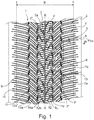
- FIG. 1 schematically shows a plan view of a partial development of a tread of a pneumatic vehicle tire with an embodiment of the invention, explained in more detail.
- Pneumatic vehicle tires designed according to the invention are, in particular, tires of radial construction for passenger cars, vans or light trucks, the tires being intended for driving under winter driving conditions.
- FIG. 11 shows a plan view of a tread 1, the equatorial plane of the tire being indicated by a line AA and the lateral edges of the ground contact area being indicated by two lines 1.
- the ground contact area corresponds, as is known, to the statically determined footprint (determined with a tire mounted on a standard rim, load at 70% of the maximum load capacity, internal pressure 85% of the standard pressure, according to ETRTO standards) and has a width B in the axial direction.
- the tread 1 has, as will be explained in more detail, a directional profiling and is to be mounted on the vehicle in such a way that it has the in Fig. 1 by the arrow R indicated rolling direction when driving forward.
- the tread 1 is noise-optimized according to a method of pitch length variation and is composed of pitches (identically designed profile sections) following one another in the circumferential direction, with the profile elements formed in one half of the tread by 30% to 60%, preferably by at least 40% %, a mean pitch length are offset in the circumferential direction to the profile elements formed in the other half of the tread.
- the tread 1 is provided with a central circumferential groove 2 running along the equatorial plane (line AA) and with oblique grooves 3, 4 extending over the width of the tread in a V-shape to one another in plan view, whereby - as will be explained - oblique grooves 3 and oblique grooves 4 in each tread half run away.
- the central circumferential groove 2 and the inclined grooves 3, 4 form the main (drainage) grooves of the tread, at least the inclined grooves 3, 4, preferably also the circumferential groove 2, to the respective intended profile depth of usually 6.5 mm to 10.0 mm.
- the rolling direction of the tire when driving forward is such that the inclined grooves 3, 4 first enter the ground contact area with their ends on the inside of the tread.
- the central circumferential groove 2 runs in a zigzag shape in plan view and is composed of groove sections 2a, which run at an angle of 3 ° to 15 °, in particular of up to 12 °, to the circumferential direction, with immediately successive groove sections 2a - correspondingly the zigzag shape - are inclined in opposite directions to one another with respect to the circumferential direction.
- the circumferential groove 2 has a groove kink with an outside bend 2 'and an inside bend 2 ".
- the circumferential groove 2 has an in particular constant width b 1 of 3.0 mm to 5.5 mm, in particular of up to 4.5 mm.
- an inclined groove 3 alternately follows an inclined groove 4 in the circumferential direction, the inclined grooves 3, 4 in each tread half running parallel to one another in plan view and the inclined grooves 3 opening into the bend outer sides 2 'of the circumferential groove 2 and the inclined grooves 4 in at a distance a 1 determined in the axial direction of 5% to 15%, in particular up to 12%, of the width B of the ground contact area in front of the equatorial plane (line AA).
- the inclined grooves 4 each run in the direction of a bend inside 2 ′′ of the central circumferential groove 2.
- the bend inside 2 ′′ of the circumferential groove 2 are therefore each essentially in the extension of the inclined grooves 4.
- the inclined grooves 3 are hereinafter also referred to as “converging inclined grooves 3" and the Inclined grooves 4 also referred to as "ending inclined grooves 4".
- the inclined grooves 3, 4 are each composed of a tread-inside groove section 5, which is slightly curved in plan view, and a shoulder-side groove section 6, which runs towards the tread edge and is more inclined towards the circumferential direction than the groove section 5.
- the groove section 5 of the inclined grooves 3 on the inside of the tread has - in relation to the center line m SR - a length l 1 projected in the axial direction, which is at least 25%, in particular at least 27%, and particularly preferably at least 30% of the width B of the ground contact area .
- the length of the groove section 5 of the ending inclined grooves 4 on the inside of the tread strip is not shown, compared to the length l 1 of the groove section 5 of the leading one Inclined grooves 3 are less by the distance a 1 already mentioned.
- the groove section 5 on the inside of the tread extends - based on a line connecting the ends of the center line m SR in the groove section 5 - to the axial direction at an angle ⁇ of 30 ° to 55 °, in particular 40 ° to 50 °.
- the shoulder-side groove section 6 extends in relation to the center line m SR to the axial direction at an angle ⁇ of 0 ° to 18 °, in particular of at least 8 °.
- a groove 7a formed further on the inside of the tread and a groove 7b further on the outside run between circumferentially adjacent inclined grooves 3, 4, the grooves 7a and 7b opening into the respective groove sections 5 on the inside of the tread.
- the grooves 7a, 7b run straight in plan view and - based on their center lines - to the circumferential direction at an angle ⁇ of 5 ° to 20 °, in particular from 13 ° to 17 °, and are inclined in opposite directions to the groove sections 5 with respect to the circumferential direction.
- the grooves 7a each have - in relation to a point located centrally on their center line - to the tire equatorial plane (line AA) in the axial direction a distance a 2 which is 4.5% to 24.5%, in particular 10% to 17% Width B of the ground contact area.
- the distance a 2 is made larger than the distance a 1 , so that the groove sections 5 of the ending oblique grooves 4 protrude on the inside of the tread with one end section beyond the grooves 7a.
- the grooves 7b are at a distance a 3 from the tire equatorial plane (line AA) in the axial direction, which is 21.5% to 41.5%, in particular 25% to 38%, of the width, based on a point located centrally on their center line B is the ground contact area.
- the grooves 7a, 7b have a continuously increasing width from their "entering" end 7 ', which first enters the ground when the tire rolls forward (arrow R), to their other, “ending” end 7 ", with a mean width of the grooves 7a, 7b, which results from the sum of the two widths at the ends 7 ', 7 "divided by two, is 2.0 mm to 5.0 mm. Furthermore, the grooves 7a, 7b have a depth of 40% to 70% of the tread depth in the radial direction, the depth of the grooves 7a further on the inside of the tread at least 55% of the tread depth and that of the grooves 7b further on the outside of the tread in particular up to 50% the tread depth is.
- a radial incision 8 extends, which has a depth of at least 1.5 mm, at most up to 100% of the profile depth, a width of 0.4 mm to 0.8 mm and extends at the mentioned angle ⁇ through the respective groove 7a, 7b.
- the profiling described gives the tread in each tread half shoulder-side tread blocks 9 and middle tread blocks 10 and 11.
- the shoulder-side tread blocks 9 extend over the area of the shoulder-side groove sections 6 and are bounded on the inside of the tread by the grooves 7b.
- the middle tread blocks 10 are formed adjacent to the shoulder-side tread blocks 9, they are laterally bounded by the grooves 7a, 7b and have a parallelogram shape in plan view.
- the tread blocks 11 lie on the central circumferential groove 2, with the tread inside groove section 5 of an inclined groove 4 ending in front of the central circumferential groove 2 running into each tread block 11, so that the tread blocks 11 in plan view - depending on the tread half - have a C-like or mirrored C- have like shape.
- an incision 12 Between the free end of each groove section 5 of the inclined grooves 4 and the central circumferential groove 2 runs an incision 12, which is simply kinked in plan view and which corresponds to the respective tread block 11, an incoming block segment 11a that first enters the ground when the tire rolls forwards when the tire is rolling, and an outgoing block segment 11b confers.
- the incision 12 has a constant depth of 70% to 100%, in particular up to 95%, of the profile depth, and also an in particular constant width b 2 of 0.5 mm to 2.0 mm, preferably 0.8 mm to 1.5 mm, and in plan view is composed of an incision section 12a extending in continuation of the respective groove section 5 and an incision section 12b opening into the central circumferential groove 2.
- the incision section 12a runs slightly curved or straight in plan view and, in the exemplary embodiment shown, has an incision wall 12a ', which extends in continuation of the groove flank of the groove section 5 which also delimits the incoming block segment 11a.
- the incision portion 12b extends, viewed in plan view, to the axial Direction at an angle ⁇ of 0 ° to 15 °, in particular of at least 5 °, preferably of 8 ° to 12 °.
- the profile blocks 9, 10, 11 are provided with incisions 13 which run parallel to one another and which traverse the profile blocks 9, 10 or the block segments 11a, 11b.
- the incisions 13 have a width of in particular 0.4 mm to 0.8 mm and at least in sections a depth of 75% to 100%, in particular up to 95%, of the profile depth.
- the incisions 13 run parallel to the shoulder-side groove sections 6 of the inclined grooves 3, 4 and therefore hardly noticeably curved at the mentioned angle ⁇ and in plan view.
- the incisions 13 formed in the middle tread blocks 10 open into the grooves 7a, 7b, run parallel to the groove sections 5 of the inclined grooves 3, 4 on the inside of the tread and therefore also barely noticeably curved at the angle ⁇ mentioned and in plan view.
- the incisions 13 run straight in plan view and to the axial direction at an angle ⁇ of 2 ° to 15 °, in particular from 7.5 ° to 12.5 °, whereby they are opposite to the respective profile block relative to the axial direction 11 co-delimiting groove sections 5 of the inclined grooves 3, 4 run.
- the size of the angle ⁇ of the incisions 13 in the profile blocks 11 corresponds to the size of the angle ⁇ of the incision section 12b of the incisions 12 separating the block segments 11a, 11b.
- the central circumferential groove 2 and the inclined grooves 3, 4 can also run in a straight line independently of one another in plan view.
- the inclined grooves 3, 4 can also have two groove sections 5, 6 that run straight in plan view or can be designed to be "continuous" and uniformly curved.
- the incisions 12, 13 can run zigzag or wave-shaped in plan view at least in sections.
- two central circumferential grooves running in the area of the tire equatorial plane can be provided, which delimit a profile rib which runs around the tire equatorial plane in the circumferential direction and is optionally structured with incisions and / or grooves.
Landscapes
- Engineering & Computer Science (AREA)
- Mechanical Engineering (AREA)
- Tires In General (AREA)
Abstract
Description
- Die Erfindung betrifft einen Fahrzeugluftreifen mit einem laufrichtungsgebunden ausgeführten Laufstreifen, welcher durch V-förmig zueinander verlaufende Schrägrillen, jeweils zwei zwischen in Umfangsrichtung benachbarten Schrägrillen verlaufende weitere Rillen und zumindest eine im Bereich der Reifenäquatorialebene verlaufende, zentrale Umfangsrille in Profilblöcke gegliedert ist, wobei die weiteren Rillen bezüglich der Umfangsrichtung gegensinnig zu den Schrägrillen geneigt sind und wobei in jeder Laufstreifenhälfte Schrägrillen verlaufen, welche in die bzw. in eine zentrale Umfangsrille einmünden.
- Ein derartiger Fahrzeugluftreifen ist beispielsweise aus der
DE 10 2007 061 148 A1 bekannt. Sämtliche der V-förmig zueinander verlaufenden Schrägrillen münden in die zentrale Umfangsrille ein. Die zwischen den Schrägrillen verlaufenden Rillen weisen eine von ihrem einlaufenden Ende zu ihrem auslaufenden Ende zunehmende Breite auf. In jedem schulterseitigen Profilblock verläuft ferner eine den Profilblock teilende Querrille. Ein Reifen mit einem derart profilierten Laufstreifen soll ein gutes Wasserdrainagevermögen aufweisen, ist allerdings im Hinblick auf seine Fahreigenschaften auf trockener und schneebedeckter Fahrbahn, insbesondere hinsichtlich seiner Handlingeigenschaften, weiter verbesserungsbedürftig. - Der Erfindung liegt daher die Aufgabe zugrunde, bei einem Fahrzeugluftreifen der eingangs genannten Art die Performance, insbesondere die Handlingeigenschaften, auf trockner und auf schneebedeckter Fahrbahn gleichermaßen zu verbessern.
- Gelöst wird die gestellte Aufgabe erfindungsgemäß dadurch, dass in jeder Laufstreifenhälfte Schrägrillen verlaufen, welche vor der bzw. vor einer zentralen Umfangsrille enden, wobei in Umfangsrichtung jeweils eine dieser Schrägrillen mit einer in die bzw. in eine zentrale Umfangsrille einmündenden Schrägrille abwechselt und wobei an der jeweiligen zentralen Umfangsrille Profilblöcke gebildet sind, in welche die vor dieser zentralen Umfangsrille endenden Schrägrillen hineinverlaufen.
- Die an der bzw. an den zentralen Umfangsrille(n) liegenden Profilblöcke weisen daher gegenüber den sonstigen Profilblöcken eine größere Umfangslänge und eine höhere Umfangs- sowie Quersteifigkeit auf, wodurch gute Handlingeigenschaften auf schneebedeckter und trockner Fahrbahn erzielt werden. Die Kombination aus in eine zentrale Umfangsrille einmündenden Schrägrillen und vor der dieser endenden Schrägrillen sorgt weiterhin für eine wirkungsvolle Wasserableitung. Die Fahreigenschaften auf trockner, nasser und schneebedeckter Fahrbahn sind daher bei einem erfindungsgemäßen Reifen auf besonders vorteilhafte Weise verbessert.
- Bevorzugter Weise weist der Laufstreifen eine einzige an der Reifenäquatorialebene verlaufende, zentrale Umfangsrille auf.
- Gemäß einer weiteren bevorzugten Ausführung ist in den Profilblöcken, in welche Schrägrillen hineinverlaufen, jeweils ein Einschnitt mit einer Tiefe von 70% bis 100% der Profiltiefe und einer Breite von 0,5 mm bis 2,0 mm, vorzugsweise von 0,8 mm bis 1,5 mm, ausgebildet, wobei der Einschnitt zwischen dem laufstreifeninnenseitigen Ende der jeweiligen Schrägrille und der bzw. einer zentralen Umfangsrille verläuft. Durch diesen Einschnitt lässt sich die Steifigkeit der an der zentralen Umfangsrille liegenden Profilblöcke derart beeinflussen, dass ein gleichmäßiger Abrieb des Laufstreifens gewährleistet ist.
- Bevorzugt ist eine Ausführung des Einschnittes, bei welcher dieser aus einem in Fortsetzung der Schrägrille verlaufenden Einschnittabschnitt und einem in die bzw. die jeweilige zentrale Umfangsrille einmündenden, zur axialen Richtung unter einem Winkel von 0° bis 15°, insbesondere von zumindest 5°, vorzugsweise von 8° bis 12°, verlaufenden Einschnittabschnitt zusammensetzt ist. Die sich dadurch ergebenden, an den Einschnitt angrenzenden Blocksegmente weisen im Bereich der an der zentralen Umfangsrille liegenden Einschnittmündung keine spitzwinkeligen Eckbereiche auf, wodurch ebenfalls ein gleichmäßiger Abrieb unterstützt wird.
- Gemäß einer weiteren bevorzugten Ausführung weist bzw. weisen die zentrale(n) Umfangsrille(n) an der Laufstreifenperipherie eine konstante Breite von 3,0 mm bis 5,5 mm, insbesondere von bis zu 4,5 mm, auf. Auch diese Maßnahme trägt zu einem gleichmäßigen Abrieb, insbesondere der bei der zentralen Umfangsrille befindlichen Profilblöcke, bei.
- Gemäß einer weiteren bevorzugten Ausführung verläuft bzw. verlaufen die zentrale(n) Umfangsrille(n) in Draufsicht zickzack-förmig und setzt bzw. setzen sich aus geraden, jeweils an einem Rillenknick aneinander anschließenden Rillenabschnitten zusammen. Der Zickzack-Verlauf der zentralen Umfangsrille(n) ermöglicht beim Fahren auf schneebedeckter Fahrbahn ein Eindringen von Schnee zur Erzielung des Effektes der Schnee-Schnee-Reibung.
- Bei dieser Ausführung der zentralen Umfangsrille(n) ist es für eine gute Wasserableitung ferner von Vorteil, wenn die in der einen Laufstreifenhälfte verlaufenden Schrägrillen zu den in der anderen Laufstreifenhälfte verlaufenden Schrägrillen in Umfangsrichtung versetzt sind, wobei die Schrägrillen, welche in die bzw. eine der zentrale(n) Umfangsrille(n) einmünden, jeweils an einer außenseitigen Knickstelle der Umfangsrille einmünden. Bevorzugt verlaufen dabei die Rillenabschnitte der zentralen Umfangsrille(n) zur Umfangsrichtung unter einem Winkel von 3° bis 15°, insbesondere von bis zu 12°.
- Gemäß einer weiteren bevorzugten Ausführung weist der Fahrzeugluftreifen einen Laufstreifen mit parallel zueinander verlaufenden Einschnitten in den Profilblöcken auf, wobei die Einschnitte in den Profilblöcken, in welche Schrägrillen hineinverlaufen, in Draufsicht zur axialen Richtung unter einem Winkel von 0° bis 15°, insbesondere von zumindest 5°, vorzugsweise von 8° bis 12°, verlaufen und die Einschnitte in den sonstigen Profilblöcken in Draufsicht parallel zu den Schrägrillen verlaufen. Derart angeordnete Einschnitte sorgen auf schneebedeckten Fahrbahnen für eine gute Traktion- und Bremsperformance.
- Für die Handlingeigenschaften des Fahrzeugluftreifens ist es von zusätzlichem Vorteil, wenn die weiteren Rillen, welche zwischen in Umfangsrichtung benachbarten Schrägrillen verlaufen, eine Tiefe von 40% bis 70% der Profiltiefe aufweisen, wobei vom Rillengrund der Rillen jeweils ein sich durch die Rille hindurcherstreckender, in radialer Richtung verlaufender Einschnitt mit einer Tiefe von mindestens 1,5 mm und einer Breite von 0,4 mm bis 0,8 mm ausgeht.
- Gemäß einer weiteren bevorzugten Ausführung setzen sich die Schrägrillen jeweils aus einem laufstreifeninnenseitigen Rillenabschnitt und einem zum Laufstreifenrand verlaufenden, zur Umfangsrichtung gegenüber dem laufstreifeninnenseitigen Rillenabschnitt stärker geneigten, schulterseitigen Rillenabschnitt zusammen, wobei die zwischen den Schrägrillen verlaufenden Rillen in die laufstreifeninnenseitigen Rillenabschnitte einmünden.
- Ferner ist es bevorzugt, wenn jene weiteren Rillen, welche weiter laufstreifeninnenseitig verlaufen, bezogen auf einen mittig auf ihrer Mittellinie liegenden Punkt, zur Reifenäquatorialebene in axialer Richtung einen Abstand aufweisen, welcher 4,5% bis 24,5%, insbesondere 10% bis 17%, der Breite (B) der Bodenaufstandsfläche beträgt
- Darüber hinaus ist es bevorzugt, wenn jeweils jene weiteren Rillen, welche weiter laufstreifenaußenseitig verlaufen, bezogen auf einen mittig auf ihrer Mittellinie liegenden Punkt, zur Reifenäquatorialebene in axialer Richtung einen Abstand aufweisen, welcher 21,5% bis 41,5%, insbesondere 25% bis 38%, der Breite der Bodenaufstandsfläche beträgt.
- Weitere Merkmale, Vorteile und Einzelheiten der Erfindung werden nun anhand der einzigen Figur,
Fig. 1 , die schematisch eine Draufsicht auf eine Teilabwicklung eines Laufstreifens eines Fahrzeugluftreifens mit einer Ausführungsvariante der Erfindung zeigt, näher erläutert. - Gemäß der Erfindung ausgeführte Fahrzeugluftreifen sind insbesondere Reifen in Radialbauart für Personenkraftwagen, Vans oder Light-Trucks, wobei die Reifen zum Fahren unter winterlichen Fahrbedingungen vorgesehen sind.
-
Fig. 1 zeigt eine Draufsicht auf einen Laufstreifen 1, wobei die Äquatorialebene des Reifens durch eine Linie A-A und die seitlichen Ränder der Bodenaufstandsfläche durch zwei Linien 1 gekennzeichnet sind. Die Bodenaufstandsfläche entspricht bekannter Weise dem statisch ermittelten Footprint (ermittelt mit einem auf einer Normfelge montierten Reifen, Last bei 70 % der maximalen Tragfähigkeit, Innendruck 85 % des Normdruckes, gemäß ETRTO-Standards) und weist in axialer Richtung eine Breite B auf. Der Laufstreifen 1 weist, wie noch genauer erläutert wird, eine laufrichtungsgebundene Profilierung auf und ist derart am Fahrzeug zu montieren, dass er die inFig. 1 durch den Pfeil R angedeutete Abrollrichtung bei Vorwärtsfahrt aufweist. - Der Laufstreifen 1 ist, wie an sich üblich, gemäß einem Verfahren der Pitchlängenvariation geräuschoptimiert und setzt sich aus in Umfangsrichtung aufeinanderfolgenden Pitches (gleichartig gestaltete Profilabschnitte) zusammen, wobei die in der einen Laufstreifenhälfte ausgebildeten Profilelemente um 30% bis 60%, vorzugsweise um mindestens 40%, einer mittleren Pitchlänge in Umfangsrichtung zu den in der anderen Laufstreifenhälfte ausgebildeten Profilelementen versetzt sind.
- Der Laufstreifen 1 ist mit einer entlang der Äquatorialebene (Linie A-A) verlaufenden zentralen Umfangsrille 2 sowie mit in Draufsicht über die Laufstreifenbreite V- förmig zueinander verlaufenden Schrägrillen 3, 4 versehen, wobei - wie noch erläutert wird - in jeder Laufstreifenhälfte Schrägrillen 3 und Schrägrillen 4 verlaufen. Die zentrale Umfangsrille 2 und die Schrägrillen 3, 4 bilden die Haupt(entwässerungs)rillen des Laufstreifens, wobei zumindest die Schrägrillen 3, 4, bevorzugter Weise auch die Umfangsrille 2, auf die jeweils vorgesehene Profiltiefe von üblicherweise 6,5 mm bis 10,0 mm ausgeführt sind. Die Abrollrichtung des Reifens bei Vorwärtsfahrt ist derart, dass die Schrägrillen 3, 4 zuerst mit ihren laufstreifeninnenseitigen Enden in die Bodenaufstandsfläche eintreten.
- Die zentrale Umfangsrille 2 verläuft beim gezeigten Ausführungsbeispiel in Draufsicht zickzack-förmig und setzt sich aus Rillenabschnitten 2a zusammen, welche zur Umfangsrichtung unter einem Winkel von 3° bis 15°, insbesondere von bis zu 12°, verlaufen, wobei unmittelbar aufeinanderfolgende Rillenabschnitte 2a - entsprechend der Zickzack-Form - bezüglich der Umfangsrichtung gegensinnig zueinander geneigt sind. Am gegenseitigen Anschlussbereich der Rillenabschnitte 2a weist die Umfangsrille 2 jeweils einen Rillenknick mit einer Knickaußenseite 2' und einer Knickinnenseite 2" auf. An der Laufstreifenperipherie weist die Umfangsrille 2 eine insbesondere konstante Breite b1 von 3,0 mm bis 5,5 mm, insbesondere von bis zu 4,5 mm, auf.
- In jeder Laufstreifenhälfte folgt in Umfangsrichtung abwechselnd eine Schrägrille 3 auf eine Schrägrille 4, wobei die Schrägrillen 3, 4 in jeder Laufstreifenhälfte in Draufsicht parallel zueinander verlaufen und wobei die Schrägrillen 3 an den Knickaußenseiten 2' der Umfangsrille 2 in diese einmünden und die Schrägrillen 4 in einem in axialer Richtung ermittelten Abstand a1 von 5% bis 15%, insbesondere von bis zu 12%, der Breite B der Bodenaufstandsfläche vor der Äquatorialebene (Linie A-A) enden bzw. auslaufen. Die Schrägrillen 4 verlaufen jeweils in Richtung zu einer Knickinnenseite 2" der zentralen Umfangsrille 2. Die Knickinnenseiten 2" der Umfangsrille 2 befinden sich daher jeweils im Wesentlichen in Verlängerung der Schrägrillen 4. Die Schrägrillen 3 werden nachfolgend auch als "einmündende Schrägrillen 3" und die Schrägrillen 4 auch als "endende Schrägrillen 4" bezeichnet.
- Die Schrägrillen 3, 4 setzen sich beim gezeigten Ausführungsbeispiel jeweils aus einem in Draufsicht leicht gebogen verlaufenden, laufstreifeninnenseitigen Rillenabschnitt 5 und einem zum Laufstreifenrand verlaufenden, zur Umfangsrichtung gegenüber dem Rillenabschnitt 5 stärker geneigten, schulterseitigen Rillenabschnitt 6 zusammen. Der laufstreifeninnenseitige Rillenabschnitt 5 der einmündenden Schrägrillen 3 weist - bezogen auf die Mittellinie mSR - eine in die axiale Richtung projizierte Länge l1 auf, welche mindestens 25%, insbesondere mindestens 27%, und besonders bevorzugt mindestens 30% der Breite B der Bodenaufstandsfläche beträgt. Die auf analoge Weise ermittelte, in
Fig. 1 nicht eingezeichnet Länge des laufstreifeninnenseitigen Rillenabschnittes 5 der endenden Schrägrillen 4 ist gegenüber der Länge l1 des Rillenabschnittes 5 der einmündenden Schrägrillen 3 um den bereits erwähnten Abstand a1 geringer. Der laufstreifeninnenseitige Rillenabschnitt 5 erstreckt sich - bezogen auf eine die im Rillenabschnitt 5 liegenden Enden der Mittellinie mSR verbindende Linie - zur axialen Richtung unter einem Winkel α von 30° bis 55°, insbesondere von 40° bis 50°. Der schulterseitige Rillenabschnitt 6 erstreckt sich bezogen auf die Mittellinie mSR zur axialen Richtung unter einem Winkel β von 0° bis 18°, insbesondere von zumindest 8°. - In jeder Laufstreifenhälfte verlaufen zwischen in Umfangsrichtung benachbarten Schrägrillen 3, 4 eine weiter laufstreifeninnenseitig ausgebildete Rille 7a und eine weiter laufstreifenaußenseitig ausgebildete Rille 7b, wobei die Rillen 7a und 7b in die jeweiligen laufstreifeninnenseitigen Rillenabschnitte 5 einmünden. Die Rillen 7a, 7b verlaufen in Draufsicht gerade sowie - bezogen auf ihre Mittellinien - zur Umfangsrichtung unter einem Winkel γ von 5° bis 20°, insbesondere von 13° bis 17°, und sind bezüglich der Umfangsrichtung gegensinnig zu den Rillenabschnitten 5 geneigt. Die Rillen 7a weisen jeweils - bezogen auf einen mittig auf ihrer Mittellinie liegenden Punkt - zur Reifenäquatorialebene (Linie A-A) in axialer Richtung einen Abstand a2 auf, welcher 4,5% bis 24,5%, insbesondere 10% bis 17%, der Breite B der Bodenaufstandsfläche beträgt. Der Abstand a2 ist größer ausgeführt als der Abstand a1, sodass die Rillenabschnitte 5 der endenden Schrägrillen 4 laufstreifeninnenseitig mit einem Endabschnitt über die Rillen 7a hinausragen. Die Rillen 7b weisen - bezogen auf einen mittig auf ihrer Mittellinie liegenden Punkt - zur Reifenäquatorialebene (Linie A-A) in axialer Richtung einen Abstand a3 auf, welcher 21,5% bis 41,5%, insbesondere 25% bis 38%, der Breite B der Bodenaufstandsfläche beträgt.
- Die Rillen 7a, 7b weisen eine von ihrem beim Abrollen des Reifens bei Vorwärtsfahrt (Pfeil R) zuerst in den Untergrund eintretenden, "einlaufenden" Ende 7' zu ihrem anderen, "auslaufenden" Ende 7" kontinuierlich zunehmende Breite auf, wobei eine mittlere Breite der Rillen 7a, 7b, welche sich aus der Summe der beiden Breiten an den Enden 7', 7" geteilt durch zwei ergibt, 2,0 mm bis 5,0 mm beträgt. Ferner weisen die Rillen 7a, 7b in radialer Richtung eine Tiefe von 40% bis 70% der Profiltiefe auf, wobei die Tiefe der weiter laufstreifeninnenseitig ausgebildeten Rillen 7a mindestens 55% der Profiltiefe und jene der weiter laufstreifenaußenseitige ausgebildeten Rillen 7b insbesondere bis zu 50% der Profiltiefe beträgt. Vom Rillengrund der Rillen 7a, 7b geht jeweils ein in radialer Richtung verlaufender Einschnitt 8 aus, welcher eine Tiefe von zumindest 1,5 mm aufweist, höchstens bis auf 100% der Profiltiefe reicht, eine Breite von 0,4 mm bis 0,8 mm aufweist und unter sich dem erwähnten Winkel γ durch die jeweilige Rille 7a, 7b hindurcherstreckt.
- Die beschriebene Profilierung verleiht dem Laufstreifen in jeder Laufstreifenhälfte schulterseitige Profilblöcke 9 sowie mittlere Profilblöcke 10 und 11. Die schulterseitigen Profilblöcke 9 erstrecken sich über den Bereich der schulterseitigen Rillenabschnitte 6 und sind laufstreifeninnenseitig von den Rillen 7b begrenzt. Die mittleren Profilblöcke 10 sind benachbart zu den schulterseitigen Profilblöcken 9 ausgebildet, wobei sie seitlich von den Rillen 7a, 7b begrenzt sind und in Draufsicht eine parallelogrammförmige Gestalt aufweisen.
- Die Profilblöcke 11 liegen an der zentralen Umfangsrille 2, wobei in jeden Profilblock 11 der laufstreifeninnenseitige Rillenabschnitt 5 einer vor der zentralen Umfangsrille 2 endenden Schrägrille 4 hineinverläuft, sodass die Profilblöcke 11 in Draufsicht - je nach Laufstreifenhälfte - eine C-artige bzw. gespiegelt C-artige Gestalt aufweisen. Zwischen dem freien Ende jedes Rillenabschnittes 5 der Schrägrillen 4 und der zentralen Umfangsrille 2 verläuft ein in Draufsicht einfach geknickten Einschnitt 12, welcher dem jeweiligen Profilblock 11, ein beim Abrollen des Reifens bei Vorwärtsfahrt zuerst in den Untergrund eintretenden, einlaufenden Blocksegment 11a und einem auslaufenden Blocksegment 11b verleiht. Der Einschnitt 12 weist in radialer Richtung eine konstante Tiefe von 70% bis 100%, insbesondere von bis zu 95%, der Profiltiefe, ferner eine insbesondere konstante Breite b2 von 0,5 mm bis 2,0 mm, vorzugsweise von 0,8 mm bis 1,5 mm, auf und setzt sich in Draufsicht aus einem in Fortsetzung des jeweiligen Rillenabschnittes 5 verlaufenden Einschnittabschnitt 12a und einem in die zentrale Umfangsrille 2 einmündenden Einschnittabschnitt 12b zusammen. Der Einschnittabschnitt 12a verläuft in Draufsicht leicht gebogen oder gerade und weist beim gezeigten Ausführungsbeispiel eine Einschnittwand 12a' auf, welche in Fortsetzung der das einlaufende Blocksegment 11a mitbegrenzenden Rillenflanke des Rillenabschnittes 5 verläuft. Der Einschnittabschnitt 12b verläuft, in Draufsicht betrachtet, zur axialen Richtung unter einem Winkel δ von 0° bis 15°, insbesondere von zumindest 5°, vorzugsweise von 8° bis 12°.
- Die Profilblöcke 9, 10, 11 sind beim gezeigten Ausführungsbeispiel mit parallel zueinander verlaufenden Einschnitten 13 versehen, welche die Profilblöcke 9, 10 bzw. die Blocksegmente 11a, 11b durchqueren. Die Einschnitte 13 weisen eine Breite von insbesondere 0,4 mm bis 0,8 mm und zumindest abschnittsweise eine Tiefe von 75% bis 100%, insbesondere bis zu 95%, der Profiltiefe auf. Innerhalb der schulterseitigen Profilblöcke 9 verlaufen die Einschnitte 13 in Draufsicht parallel zu den schulterseitigen Rillenabschnitten 6 der Schrägrillen 3, 4 und daher unter dem erwähnten Winkel β sowie in Draufsicht kaum merkbar gebogen. Die in den mittleren Profilblöcken 10 ausgebildeten Einschnitte 13 münden in die Rillen 7a, 7b ein, verlaufen parallel zu den laufstreifeninnenseitigen Rillenabschnitten 5 der Schrägrillen 3, 4 und daher unter dem erwähnten Winkel α sowie in Draufsicht ebenfalls kaum merkbar gebogen. In den Profilblöcken 11 verlaufen die Einschnitte 13 in Draufsicht gerade sowie zur axialen Richtung unter einem Winkel ε von 2° bis 15°, insbesondere von 7,5° bis 12,5°, wobei sie relativ zur axialen Richtung gegensinnig zu den den jeweiligen Profilblock 11 mitbegrenzenden Rillenabschnitten 5 der Schrägrillen 3, 4 verlaufen. Beim gezeigten Ausführungsbeispiel stimmt die Größe des Winkels ε der Einschnitte 13 in den Profilblöcken 11 mit der Größe des Winkels δ des Einschnittabschnittes 12b der die Blocksegmente 11a, 11b trennenden Einschnitte 12 überein.
- Die Erfindung ist auf die dargestellte und beschriebene Ausführungsvariante nicht beschränkt.
- Insbesondere können die zentrale Umfangsrille 2 sowie die Schrägrillen 3, 4 unabhängig voneinander in Draufsicht auch gerade verlaufen. Die Schrägrillen 3, 4 können ferner auch zwei in Draufsicht gerade verlaufende Rillenabschnitte 5, 6 aufweisen oder "durchgehend", einheitlich gebogen ausgeführt sein. Die Einschnitte 12, 13 können in Draufsicht zumindest abschnittsweise zick-zack- oder wellenförmig verlaufen.
- Ferner können zwei im Bereich der Reifenäquatorialebene verlaufende zentrale Umfangsrillen vorgesehen sein, welche eine an der Reifenäquatorialebene in Umfangsrichtung umlaufende, gegebenenfalls mit Einschnitten und/oder Rillen strukturierte Profilrippe begrenzen.
-
- 1
- Laufstreifen
- 2
- zentrale Umfangsrille
- 2'
- Knickaußenseite
- 2"
- Knickinnenseite
- 2a
- Rillenabschnitt
- 3
- Schrägrille
- 4
- Schrägrille
- 5
- laufstreifeninnenseitiger Rillenabschnitt
- 6
- schulterseitiger Rillenabschnitt
- 7a, 7b
- Rille
- 7'
- einlaufendes Ende
- 7"
- auslaufendes Ende
- 8
- Einschnitt
- 9
- schulterseitiger Profilblock
- 10
- mittlerer Profilblock
- 11
- Doppelblock
- 11a
- einlaufendes Blocksegment
- 11b
- auslaufendes Blocksegment
- 12
- Einschnitt
- 12a
- Einschnittabschnitt
- 12a'
- Einschnittwand
- 12b
- Einschnittabschnitt
- 13
- Einschnitt
- A-A
- Linie (Äquatorialebene)
- a1, a2, a3
- Abstand
- b1, b2
- Breite
- B
- Breite
- l
- Linie (seitlicher Rand der Bodenaufstandsfläche)
- mSR
- Mittellinie
- R
- Pfeil (Abrollrichtung)
- α, β, γ, δ, ε
- Winkel
Claims (14)
- Fahrzeugluftreifen mit einem laufrichtungsgebunden ausgeführten Laufstreifen (1), welcher durch V-förmig zueinander verlaufende Schrägrillen (3, 4), jeweils zwei zwischen in Umfangsrichtung benachbarten Schrägrillen (3, 4) verlaufende weitere Rillen (7a, 7b) und zumindest eine im Bereich der Reifenäquatorialebene (A-A) verlaufende, zentrale Umfangsrille (2) in Profilblöcke (9, 10, 11) gegliedert ist, wobei die weiteren Rillen (7a, 7a) bezüglich der Umfangsrichtung gegensinnig zu den Schrägrillen (3, 4) geneigt sind und wobei in jeder Laufstreifenhälfte Schrägrillen (3) verlaufen, welche in die bzw. in eine zentrale Umfangsrille (2) einmünden,
dadurch geknnzeichnet,
dass in jeder Laufstreifenhälfte Schrägrillen (4) verlaufen, welche vor der bzw. vor einer zentralen Umfangsrille (2) enden, wobei in Umfangsrichtung jeweils eine dieser Schrägrillen (4) mit einer in die bzw. in eine zentrale Umfangsrille (2) einmündenden Schrägrille (3) abwechselt und wobei an der jeweiligen zentralen Umfangsrille (2) Profilblöcke (11) gebildet sind, in welche die vor dieser zentralen Umfangsrille (2) endenden Schrägrillen (4) hineinverlaufen. - Fahrzeugluftreifen nach Anspruch 1, dadurch gekennzeichnet, dass der Laufstreifen eine einzige an der Reifenäquatorialebene verlaufende, zentrale Umfangsrille (2) aufweist.
- Fahrzeugluftreifen nach Anspruch 1 oder 2, dadurch gekennzeichnet, dass in den Profilblöcken (11), in welche Schrägrillen (4) hineinverlaufen, jeweils ein Einschnitt (12) mit einer Tiefe von 70% bis 100% der Profiltiefe und einer Breite (b2) von 0,5 mm bis 2,0 mm, vorzugsweise von 0,8 mm bis 1,5 mm, ausgebildet ist, wobei der Einschnitt (12) zwischen dem laufstreifeninnenseitigen Ende der jeweiligen Schrägrille (4) und der bzw. einer zentralen Umfangsrille (2) verläuft.
- Fahrzeugluftreifen nach einem Anspruch 3, dadurch gekennzeichnet, dass sich der Einschnitt (12) aus einem in Fortsetzung der Schrägrille (4) verlaufenden Einschnittabschnitt (12a) und einem in die bzw. die jeweilige zentrale Umfangsrille (2) einmündenden, zur axialen Richtung unter einem Winkel (δ) von 0° bis 15°, insbesondere von zumindest 5°, vorzugsweise von 8° bis 12°, verlaufenden Einschnittabschnitt (12b) zusammensetzt.
- Fahrzeugluftreifen nach einem der Ansprüche 1 bis 4, dadurch gekennzeichnet, dass die zentrale(n) Umfangsrille(n) (2) an der Laufstreifenperipherie eine konstante Breite (b1) von 3,0 mm bis 5,5 mm, insbesondere von bis zu 4,5 mm, aufweist bzw. aufweisen.
- Fahrzeugluftreifen nach einem der Ansprüche 1 bis 5, dadurch gekennzeichnet, dass die zentrale(n) Umfangsrille(n) (2) in Draufsicht zickzack-förmig verläuft bzw. verlaufen und sich aus geraden, jeweils an einem Rillenknick aneinander anschließenden Rillenabschnitten (2a) zusammensetzt bzw. zusammensetzen.
- Fahrzeugluftreifen nach Anspruch 6, dadurch gekennzeichnet, dass die in der einen Laufstreifenhälfte verlaufenden Schrägrillen (3, 4) zu den in der anderen Laufstreifenhälfte verlaufenden Schrägrillen (3, 4) in Umfangsrichtung versetzt sind, wobei die Schrägrillen (3), welche in die bzw. eine der zentrale(n) Umfangsrille(n) (2) einmünden, jeweils an einer außenseitigen Knickstelle der zentralen Umfangsrille (2) einmünden.
- Fahrzeugluftreifen nach Anspruch 6 oder 7, dadurch gekennzeichnet, dass die Rillenabschnitte (2a) der zentralen Umfangsrille(n) (2) zur Umfangsrichtung unter einem Winkel von 3° bis 15°, insbesondere von bis zu 12°, verlaufen.
- Fahrzeugluftreifen mit einem Laufstreifen mit parallel zueinander verlaufenden Einschnitten (12) in den Profilblöcken (9, 10, 11a, 11b) nach einem der Ansprüche 1 bis 8, dadurch gekennzeichnet, dass die Einschnitte (12) in den Profilblöcken (11), in welche Schrägrillen (4) hineinverlaufen, in Draufsicht zur axialen Richtung unter einem Winkel (δ) von 0° bis 15°, insbesondere von zumindest 5°, vorzugsweise von 8° bis 12°, verlaufen und dass die Einschnitte (12) in den sonstigen Profilblöcken (9, 10) in Draufsicht parallel zu den Schrägrillen (3, 4) verlaufen.
- Fahrzeugluftreifen nach einem der Ansprüche 1 bis 9, dadurch gekennzeichnet, dass die Rillen (7a, 7b), welche zwischen in Umfangsrichtung benachbarten Schrägrillen (3, 4) verlaufen, eine Tiefe von 40% bis 70% der Profiltiefe aufweisen, wobei vom Rillengrund der Rillen (7a, 7b) jeweils ein sich durch die Rille (7a, 7b) hindurcherstreckender, in radialer Richtung verlaufender Einschnitt (8) mit einer Tiefe von mindestens 1,5 mm und einer Breite von 0,4 mm bis 0,8 mm ausgeht.
- Fahrzeugluftreifen nach einem der Ansprüche 1 bis 10, dadurch gekennzeichnet, dass sich die Schrägrillen (3, 4) jeweils aus einem laufstreifeninnenseitigen Rillenabschnitt (5) und einem zum Laufstreifenrand verlaufenden, zur Umfangsrichtung gegenüber dem laufstreifeninnenseitigen Rillenabschnitt (5) stärker geneigten, schulterseitigen Rillenabschnitt (6) zusammensetzten, wobei die zwischen den Schrägrillen (3, 4) verlaufenden Rillen (7a, 7b) in die laufstreifeninnenseitigen Rillenabschnitte (5) einmünden.
- Fahrzeugluftreifen nach einem der Ansprüche 1 bis 11, dadurch gekennzeichnet, dass die Schrägrillen (4), welche vor der bzw. vor einer zentralen Umfangsrille (2) enden, vor der Reifenäquatorialebene (A-A) in einem in axialer Richtung ermittelten Abstand (a1) von 5% bis 15%, insbesondere von bis zu 12%, der Breite (B) der Bodenaufstandsfläche enden.
- Fahrzeugluftreifen nach einem der Ansprüche 1 bis 12, dadurch gekennzeichnet, dass jeweils jene weiteren Rillen (7a), welche weiter laufstreifeninnenseitig verlaufen, bezogen auf einen mittig auf ihrer Mittellinie liegenden Punkt, zur Reifenäquatorialebene (A-A)in axialer Richtung einen Abstand (a2) aufweisen, welcher 4,5% bis 24,5%, insbesondere 10% bis 17%, der Breite (B) der Bodenaufstandsfläche beträgt.
- Fahrzeugluftreifen nach einem der Ansprüche 1 bis 13, dadurch gekennzeichnet, dass jene weiteren Rillen (7b), welche weiter laufstreifenaußenseitig verlaufen, bezogen auf einen mittig auf ihrer Mittellinie liegenden Punkt, zur Reifenäquatorialebene (A-A) in axialer Richtung einen Abstand (a3) aufweisen, welcher 21,5% bis 41,5%, insbesondere 25% bis 38%, der Breite (B) der Bodenaufstandsfläche beträgt.
Applications Claiming Priority (1)
| Application Number | Priority Date | Filing Date | Title |
|---|---|---|---|
| DE102019213044.5A DE102019213044A1 (de) | 2019-08-29 | 2019-08-29 | Fahrzeugluftreifen |
Publications (2)
| Publication Number | Publication Date |
|---|---|
| EP3785938A1 true EP3785938A1 (de) | 2021-03-03 |
| EP3785938B1 EP3785938B1 (de) | 2022-06-15 |
Family
ID=71950458
Family Applications (1)
| Application Number | Title | Priority Date | Filing Date |
|---|---|---|---|
| EP20189523.2A Active EP3785938B1 (de) | 2019-08-29 | 2020-08-05 | Fahrzeugluftreifen |
Country Status (2)
| Country | Link |
|---|---|
| EP (1) | EP3785938B1 (de) |
| DE (1) | DE102019213044A1 (de) |
Cited By (1)
| Publication number | Priority date | Publication date | Assignee | Title |
|---|---|---|---|---|
| WO2022253372A1 (de) * | 2021-06-03 | 2022-12-08 | Continental Reifen Deutschland Gmbh | Fahrzeugluftreifen |
Families Citing this family (2)
| Publication number | Priority date | Publication date | Assignee | Title |
|---|---|---|---|---|
| DE102022208785A1 (de) | 2022-08-25 | 2024-03-07 | Continental Reifen Deutschland Gmbh | Fahrzeugluftreifen |
| DE102022208784A1 (de) | 2022-08-25 | 2024-03-07 | Continental Reifen Deutschland Gmbh | Fahrzeugluftreifen |
Citations (4)
| Publication number | Priority date | Publication date | Assignee | Title |
|---|---|---|---|---|
| EP0604383A1 (de) * | 1992-12-24 | 1994-06-29 | Semperit Reifen Aktiengesellschaft | Fahrzeugluftreifen |
| DE19705156A1 (de) * | 1996-02-12 | 1997-10-30 | Semperit Reifen | Fahrzeugluftreifen |
| EP1752314A1 (de) * | 2004-05-27 | 2007-02-14 | Bridgestone Corporation | Luftreifen |
| DE102007061148A1 (de) * | 2007-12-17 | 2009-06-18 | Continental Aktiengesellschaft | Fahrzeugluftreifen |
-
2019
- 2019-08-29 DE DE102019213044.5A patent/DE102019213044A1/de active Pending
-
2020
- 2020-08-05 EP EP20189523.2A patent/EP3785938B1/de active Active
Patent Citations (4)
| Publication number | Priority date | Publication date | Assignee | Title |
|---|---|---|---|---|
| EP0604383A1 (de) * | 1992-12-24 | 1994-06-29 | Semperit Reifen Aktiengesellschaft | Fahrzeugluftreifen |
| DE19705156A1 (de) * | 1996-02-12 | 1997-10-30 | Semperit Reifen | Fahrzeugluftreifen |
| EP1752314A1 (de) * | 2004-05-27 | 2007-02-14 | Bridgestone Corporation | Luftreifen |
| DE102007061148A1 (de) * | 2007-12-17 | 2009-06-18 | Continental Aktiengesellschaft | Fahrzeugluftreifen |
Cited By (1)
| Publication number | Priority date | Publication date | Assignee | Title |
|---|---|---|---|---|
| WO2022253372A1 (de) * | 2021-06-03 | 2022-12-08 | Continental Reifen Deutschland Gmbh | Fahrzeugluftreifen |
Also Published As
| Publication number | Publication date |
|---|---|
| DE102019213044A1 (de) | 2021-03-04 |
| EP3785938B1 (de) | 2022-06-15 |
Similar Documents
| Publication | Publication Date | Title |
|---|---|---|
| EP3589500B1 (de) | Fahrzeugluftreifen | |
| EP3388256B1 (de) | Fahrzeugluftreifen | |
| EP3785938B1 (de) | Fahrzeugluftreifen | |
| EP1695844B1 (de) | Fahrzeugreifen mit einem Laufstreifenprofil | |
| EP3009275B1 (de) | Fahrzeugluftreifen | |
| WO2017092896A1 (de) | Fahrzeugluftreifen | |
| EP3383671B1 (de) | Fahrzeugluftreifen | |
| EP4171972B1 (de) | Fahrzeugluftreifen | |
| EP3708388B1 (de) | Fahrzeugluftreifen | |
| EP3724006A1 (de) | Nutzfahrzeugreifen | |
| EP3441241B1 (de) | Fahrzeugluftreifen | |
| EP2138329B1 (de) | Laufflächenprofil für einen Fahrzeugluftreifen | |
| EP3300925B1 (de) | Fahrzeugluftreifen | |
| EP3888948B1 (de) | Fahrzeugluftreifen, insbesondere nutzfahrzeugreifen | |
| EP2138328B1 (de) | Fahrzeugluftreifen | |
| EP3715146B1 (de) | Fahrzeugluftreifen | |
| EP1695845B1 (de) | Fahrzeugreifen mit einem Laufstreifenprofil | |
| EP3789213B1 (de) | Fahrzeugluftreifen | |
| EP3825151B1 (de) | Fahrzeugluftreifen mit einem laufstreifen | |
| EP3450216B1 (de) | Fahrzeugluftreifen | |
| WO2024041705A1 (de) | Fahrzeugluftreifen | |
| WO2024041706A1 (de) | Fahrzeugluftreifen | |
| EP4257375A1 (de) | Fahrzeugluftreifen | |
| EP3310592B1 (de) | Fahrzeugluftreifen | |
| EP4166355A1 (de) | Fahrzeugluftreifen |
Legal Events
| Date | Code | Title | Description |
|---|---|---|---|
| PUAI | Public reference made under article 153(3) epc to a published international application that has entered the european phase |
Free format text: ORIGINAL CODE: 0009012 |
|
| STAA | Information on the status of an ep patent application or granted ep patent |
Free format text: STATUS: THE APPLICATION HAS BEEN PUBLISHED |
|
| AK | Designated contracting states |
Kind code of ref document: A1 Designated state(s): AL AT BE BG CH CY CZ DE DK EE ES FI FR GB GR HR HU IE IS IT LI LT LU LV MC MK MT NL NO PL PT RO RS SE SI SK SM TR |
|
| AX | Request for extension of the european patent |
Extension state: BA ME |
|
| STAA | Information on the status of an ep patent application or granted ep patent |
Free format text: STATUS: REQUEST FOR EXAMINATION WAS MADE |
|
| 17P | Request for examination filed |
Effective date: 20210903 |
|
| RBV | Designated contracting states (corrected) |
Designated state(s): AL AT BE BG CH CY CZ DE DK EE ES FI FR GB GR HR HU IE IS IT LI LT LU LV MC MK MT NL NO PL PT RO RS SE SI SK SM TR |
|
| RIC1 | Information provided on ipc code assigned before grant |
Ipc: B60C 11/12 20060101ALI20211208BHEP Ipc: B60C 11/03 20060101AFI20211208BHEP |
|
| GRAP | Despatch of communication of intention to grant a patent |
Free format text: ORIGINAL CODE: EPIDOSNIGR1 |
|
| STAA | Information on the status of an ep patent application or granted ep patent |
Free format text: STATUS: GRANT OF PATENT IS INTENDED |
|
| INTG | Intention to grant announced |
Effective date: 20220126 |
|
| GRAS | Grant fee paid |
Free format text: ORIGINAL CODE: EPIDOSNIGR3 |
|
| GRAA | (expected) grant |
Free format text: ORIGINAL CODE: 0009210 |
|
| STAA | Information on the status of an ep patent application or granted ep patent |
Free format text: STATUS: THE PATENT HAS BEEN GRANTED |
|
| AK | Designated contracting states |
Kind code of ref document: B1 Designated state(s): AL AT BE BG CH CY CZ DE DK EE ES FI FR GB GR HR HU IE IS IT LI LT LU LV MC MK MT NL NO PL PT RO RS SE SI SK SM TR |
|
| REG | Reference to a national code |
Ref country code: CH Ref legal event code: EP Ref country code: GB Ref legal event code: FG4D Free format text: NOT ENGLISH |
|
| REG | Reference to a national code |
Ref country code: IE Ref legal event code: FG4D Free format text: LANGUAGE OF EP DOCUMENT: GERMAN |
|
| REG | Reference to a national code |
Ref country code: DE Ref legal event code: R096 Ref document number: 502020001235 Country of ref document: DE |
|
| REG | Reference to a national code |
Ref country code: AT Ref legal event code: REF Ref document number: 1498147 Country of ref document: AT Kind code of ref document: T Effective date: 20220715 |
|
| REG | Reference to a national code |
Ref country code: NL Ref legal event code: FP |
|
| REG | Reference to a national code |
Ref country code: NO Ref legal event code: T2 Effective date: 20220615 |
|
| REG | Reference to a national code |
Ref country code: SE Ref legal event code: TRGR |
|
| REG | Reference to a national code |
Ref country code: LT Ref legal event code: MG9D |
|
| PG25 | Lapsed in a contracting state [announced via postgrant information from national office to epo] |
Ref country code: LT Free format text: LAPSE BECAUSE OF FAILURE TO SUBMIT A TRANSLATION OF THE DESCRIPTION OR TO PAY THE FEE WITHIN THE PRESCRIBED TIME-LIMIT Effective date: 20220615 Ref country code: HR Free format text: LAPSE BECAUSE OF FAILURE TO SUBMIT A TRANSLATION OF THE DESCRIPTION OR TO PAY THE FEE WITHIN THE PRESCRIBED TIME-LIMIT Effective date: 20220615 Ref country code: GR Free format text: LAPSE BECAUSE OF FAILURE TO SUBMIT A TRANSLATION OF THE DESCRIPTION OR TO PAY THE FEE WITHIN THE PRESCRIBED TIME-LIMIT Effective date: 20220916 Ref country code: FI Free format text: LAPSE BECAUSE OF FAILURE TO SUBMIT A TRANSLATION OF THE DESCRIPTION OR TO PAY THE FEE WITHIN THE PRESCRIBED TIME-LIMIT Effective date: 20220615 Ref country code: BG Free format text: LAPSE BECAUSE OF FAILURE TO SUBMIT A TRANSLATION OF THE DESCRIPTION OR TO PAY THE FEE WITHIN THE PRESCRIBED TIME-LIMIT Effective date: 20220915 |
|
| PG25 | Lapsed in a contracting state [announced via postgrant information from national office to epo] |
Ref country code: RS Free format text: LAPSE BECAUSE OF FAILURE TO SUBMIT A TRANSLATION OF THE DESCRIPTION OR TO PAY THE FEE WITHIN THE PRESCRIBED TIME-LIMIT Effective date: 20220615 Ref country code: LV Free format text: LAPSE BECAUSE OF FAILURE TO SUBMIT A TRANSLATION OF THE DESCRIPTION OR TO PAY THE FEE WITHIN THE PRESCRIBED TIME-LIMIT Effective date: 20220615 |
|
| PG25 | Lapsed in a contracting state [announced via postgrant information from national office to epo] |
Ref country code: SM Free format text: LAPSE BECAUSE OF FAILURE TO SUBMIT A TRANSLATION OF THE DESCRIPTION OR TO PAY THE FEE WITHIN THE PRESCRIBED TIME-LIMIT Effective date: 20220615 Ref country code: SK Free format text: LAPSE BECAUSE OF FAILURE TO SUBMIT A TRANSLATION OF THE DESCRIPTION OR TO PAY THE FEE WITHIN THE PRESCRIBED TIME-LIMIT Effective date: 20220615 Ref country code: RO Free format text: LAPSE BECAUSE OF FAILURE TO SUBMIT A TRANSLATION OF THE DESCRIPTION OR TO PAY THE FEE WITHIN THE PRESCRIBED TIME-LIMIT Effective date: 20220615 Ref country code: PT Free format text: LAPSE BECAUSE OF FAILURE TO SUBMIT A TRANSLATION OF THE DESCRIPTION OR TO PAY THE FEE WITHIN THE PRESCRIBED TIME-LIMIT Effective date: 20221017 Ref country code: ES Free format text: LAPSE BECAUSE OF FAILURE TO SUBMIT A TRANSLATION OF THE DESCRIPTION OR TO PAY THE FEE WITHIN THE PRESCRIBED TIME-LIMIT Effective date: 20220615 Ref country code: EE Free format text: LAPSE BECAUSE OF FAILURE TO SUBMIT A TRANSLATION OF THE DESCRIPTION OR TO PAY THE FEE WITHIN THE PRESCRIBED TIME-LIMIT Effective date: 20220615 Ref country code: CZ Free format text: LAPSE BECAUSE OF FAILURE TO SUBMIT A TRANSLATION OF THE DESCRIPTION OR TO PAY THE FEE WITHIN THE PRESCRIBED TIME-LIMIT Effective date: 20220615 |
|
| PG25 | Lapsed in a contracting state [announced via postgrant information from national office to epo] |
Ref country code: PL Free format text: LAPSE BECAUSE OF FAILURE TO SUBMIT A TRANSLATION OF THE DESCRIPTION OR TO PAY THE FEE WITHIN THE PRESCRIBED TIME-LIMIT Effective date: 20220615 Ref country code: IS Free format text: LAPSE BECAUSE OF FAILURE TO SUBMIT A TRANSLATION OF THE DESCRIPTION OR TO PAY THE FEE WITHIN THE PRESCRIBED TIME-LIMIT Effective date: 20221015 |
|
| REG | Reference to a national code |
Ref country code: DE Ref legal event code: R097 Ref document number: 502020001235 Country of ref document: DE |
|
| PG25 | Lapsed in a contracting state [announced via postgrant information from national office to epo] |
Ref country code: MC Free format text: LAPSE BECAUSE OF FAILURE TO SUBMIT A TRANSLATION OF THE DESCRIPTION OR TO PAY THE FEE WITHIN THE PRESCRIBED TIME-LIMIT Effective date: 20220615 Ref country code: AL Free format text: LAPSE BECAUSE OF FAILURE TO SUBMIT A TRANSLATION OF THE DESCRIPTION OR TO PAY THE FEE WITHIN THE PRESCRIBED TIME-LIMIT Effective date: 20220615 |
|
| PLBE | No opposition filed within time limit |
Free format text: ORIGINAL CODE: 0009261 |
|
| STAA | Information on the status of an ep patent application or granted ep patent |
Free format text: STATUS: NO OPPOSITION FILED WITHIN TIME LIMIT |
|
| PG25 | Lapsed in a contracting state [announced via postgrant information from national office to epo] |
Ref country code: LU Free format text: LAPSE BECAUSE OF NON-PAYMENT OF DUE FEES Effective date: 20220805 Ref country code: DK Free format text: LAPSE BECAUSE OF FAILURE TO SUBMIT A TRANSLATION OF THE DESCRIPTION OR TO PAY THE FEE WITHIN THE PRESCRIBED TIME-LIMIT Effective date: 20220615 |
|
| REG | Reference to a national code |
Ref country code: BE Ref legal event code: MM Effective date: 20220831 |
|
| 26N | No opposition filed |
Effective date: 20230316 |
|
| PG25 | Lapsed in a contracting state [announced via postgrant information from national office to epo] |
Ref country code: SI Free format text: LAPSE BECAUSE OF FAILURE TO SUBMIT A TRANSLATION OF THE DESCRIPTION OR TO PAY THE FEE WITHIN THE PRESCRIBED TIME-LIMIT Effective date: 20220615 |
|
| P01 | Opt-out of the competence of the unified patent court (upc) registered |
Effective date: 20230602 |
|
| PG25 | Lapsed in a contracting state [announced via postgrant information from national office to epo] |
Ref country code: IE Free format text: LAPSE BECAUSE OF NON-PAYMENT OF DUE FEES Effective date: 20220805 Ref country code: FR Free format text: LAPSE BECAUSE OF NON-PAYMENT OF DUE FEES Effective date: 20220815 |
|
| PG25 | Lapsed in a contracting state [announced via postgrant information from national office to epo] |
Ref country code: BE Free format text: LAPSE BECAUSE OF NON-PAYMENT OF DUE FEES Effective date: 20220831 |
|
| PGFP | Annual fee paid to national office [announced via postgrant information from national office to epo] |
Ref country code: NL Payment date: 20230821 Year of fee payment: 4 |
|
| PGFP | Annual fee paid to national office [announced via postgrant information from national office to epo] |
Ref country code: NO Payment date: 20230824 Year of fee payment: 4 |
|
| PGFP | Annual fee paid to national office [announced via postgrant information from national office to epo] |
Ref country code: SE Payment date: 20230821 Year of fee payment: 4 Ref country code: DE Payment date: 20230831 Year of fee payment: 4 |
|
| PG25 | Lapsed in a contracting state [announced via postgrant information from national office to epo] |
Ref country code: IT Free format text: LAPSE BECAUSE OF FAILURE TO SUBMIT A TRANSLATION OF THE DESCRIPTION OR TO PAY THE FEE WITHIN THE PRESCRIBED TIME-LIMIT Effective date: 20220615 |
|
| REG | Reference to a national code |
Ref country code: DE Ref legal event code: R081 Ref document number: 502020001235 Country of ref document: DE Owner name: CONTINENTAL REIFEN DEUTSCHLAND GMBH, DE Free format text: FORMER OWNER: CONTINENTAL REIFEN DEUTSCHLAND GMBH, 30165 HANNOVER, DE |
|
| REG | Reference to a national code |
Ref country code: CH Ref legal event code: PL |
|
| PG25 | Lapsed in a contracting state [announced via postgrant information from national office to epo] |
Ref country code: CY Free format text: LAPSE BECAUSE OF FAILURE TO SUBMIT A TRANSLATION OF THE DESCRIPTION OR TO PAY THE FEE WITHIN THE PRESCRIBED TIME-LIMIT Effective date: 20220615 Ref country code: CH Free format text: LAPSE BECAUSE OF NON-PAYMENT OF DUE FEES Effective date: 20230831 |