EP3785874A1 - Verfahren zur herstellung eines betriebsmitteltanks - Google Patents
Verfahren zur herstellung eines betriebsmitteltanks Download PDFInfo
- Publication number
- EP3785874A1 EP3785874A1 EP20193297.7A EP20193297A EP3785874A1 EP 3785874 A1 EP3785874 A1 EP 3785874A1 EP 20193297 A EP20193297 A EP 20193297A EP 3785874 A1 EP3785874 A1 EP 3785874A1
- Authority
- EP
- European Patent Office
- Prior art keywords
- mold core
- plastic
- fluid tank
- operating fluid
- mold
- Prior art date
- Legal status (The legal status is an assumption and is not a legal conclusion. Google has not performed a legal analysis and makes no representation as to the accuracy of the status listed.)
- Granted
Links
- 238000004519 manufacturing process Methods 0.000 title claims abstract description 13
- 238000000034 method Methods 0.000 title claims description 30
- 239000011162 core material Substances 0.000 claims abstract description 159
- 229920003023 plastic Polymers 0.000 claims abstract description 87
- 239000004033 plastic Substances 0.000 claims abstract description 87
- 239000012530 fluid Substances 0.000 claims abstract description 84
- 238000010137 moulding (plastic) Methods 0.000 claims abstract description 19
- 230000009969 flowable effect Effects 0.000 claims abstract description 6
- 239000000919 ceramic Substances 0.000 claims abstract description 4
- 239000000463 material Substances 0.000 claims description 12
- 238000000465 moulding Methods 0.000 claims description 5
- 239000011324 bead Substances 0.000 claims description 4
- 239000006260 foam Substances 0.000 claims description 4
- 239000004576 sand Substances 0.000 claims description 4
- 238000007789 sealing Methods 0.000 claims description 4
- 238000010146 3D printing Methods 0.000 claims description 2
- 238000001746 injection moulding Methods 0.000 description 8
- 239000007788 liquid Substances 0.000 description 7
- 239000011159 matrix material Substances 0.000 description 7
- 239000008187 granular material Substances 0.000 description 6
- 230000002787 reinforcement Effects 0.000 description 6
- 239000011230 binding agent Substances 0.000 description 5
- 239000002828 fuel tank Substances 0.000 description 5
- -1 polypropylene Polymers 0.000 description 4
- 239000012783 reinforcing fiber Substances 0.000 description 4
- 239000004743 Polypropylene Substances 0.000 description 3
- 239000000446 fuel Substances 0.000 description 3
- 235000011837 pasties Nutrition 0.000 description 3
- 229920001155 polypropylene Polymers 0.000 description 3
- 239000011265 semifinished product Substances 0.000 description 3
- 239000002904 solvent Substances 0.000 description 3
- 229920001169 thermoplastic Polymers 0.000 description 3
- 239000004416 thermosoftening plastic Substances 0.000 description 3
- XLYOFNOQVPJJNP-UHFFFAOYSA-N water Substances O XLYOFNOQVPJJNP-UHFFFAOYSA-N 0.000 description 3
- OKTJSMMVPCPJKN-UHFFFAOYSA-N Carbon Chemical compound [C] OKTJSMMVPCPJKN-UHFFFAOYSA-N 0.000 description 2
- 229920000219 Ethylene vinyl alcohol Polymers 0.000 description 2
- 239000004698 Polyethylene Substances 0.000 description 2
- 239000004918 carbon fiber reinforced polymer Substances 0.000 description 2
- 229910010293 ceramic material Inorganic materials 0.000 description 2
- 239000011152 fibreglass Substances 0.000 description 2
- 229920001903 high density polyethylene Polymers 0.000 description 2
- 239000004700 high-density polyethylene Substances 0.000 description 2
- 239000000155 melt Substances 0.000 description 2
- 239000002184 metal Substances 0.000 description 2
- 239000003921 oil Substances 0.000 description 2
- 229920000573 polyethylene Polymers 0.000 description 2
- 230000001105 regulatory effect Effects 0.000 description 2
- 230000003014 reinforcing effect Effects 0.000 description 2
- 239000012815 thermoplastic material Substances 0.000 description 2
- LFQSCWFLJHTTHZ-UHFFFAOYSA-N Ethanol Chemical compound CCO LFQSCWFLJHTTHZ-UHFFFAOYSA-N 0.000 description 1
- 229920002430 Fibre-reinforced plastic Polymers 0.000 description 1
- 229920002292 Nylon 6 Polymers 0.000 description 1
- 239000004952 Polyamide Substances 0.000 description 1
- 239000004793 Polystyrene Substances 0.000 description 1
- 239000002253 acid Substances 0.000 description 1
- 239000000853 adhesive Substances 0.000 description 1
- 230000001070 adhesive effect Effects 0.000 description 1
- 230000005540 biological transmission Effects 0.000 description 1
- 239000011248 coating agent Substances 0.000 description 1
- 238000000576 coating method Methods 0.000 description 1
- 229920001577 copolymer Polymers 0.000 description 1
- 229920003020 cross-linked polyethylene Polymers 0.000 description 1
- 239000004703 cross-linked polyethylene Substances 0.000 description 1
- 230000001419 dependent effect Effects 0.000 description 1
- 238000006073 displacement reaction Methods 0.000 description 1
- 239000004715 ethylene vinyl alcohol Substances 0.000 description 1
- 239000003000 extruded plastic Substances 0.000 description 1
- 239000000835 fiber Substances 0.000 description 1
- 239000011151 fibre-reinforced plastic Substances 0.000 description 1
- 239000011521 glass Substances 0.000 description 1
- 238000002347 injection Methods 0.000 description 1
- 239000007924 injection Substances 0.000 description 1
- 229910052500 inorganic mineral Inorganic materials 0.000 description 1
- 238000003754 machining Methods 0.000 description 1
- 239000011707 mineral Substances 0.000 description 1
- 239000000203 mixture Substances 0.000 description 1
- 229920002647 polyamide Polymers 0.000 description 1
- 229920002223 polystyrene Polymers 0.000 description 1
- 238000003825 pressing Methods 0.000 description 1
- 239000000047 product Substances 0.000 description 1
- 238000005096 rolling process Methods 0.000 description 1
- 230000011218 segmentation Effects 0.000 description 1
- AFJYYKSVHJGXSN-KAJWKRCWSA-N selamectin Chemical compound O1[C@@H](C)[C@H](O)[C@@H](OC)C[C@@H]1O[C@@H]1C(/C)=C/C[C@@H](O[C@]2(O[C@@H]([C@@H](C)CC2)C2CCCCC2)C2)C[C@@H]2OC(=O)[C@@H]([C@]23O)C=C(C)C(=N\O)/[C@H]3OC\C2=C/C=C/[C@@H]1C AFJYYKSVHJGXSN-KAJWKRCWSA-N 0.000 description 1
- 239000007787 solid Substances 0.000 description 1
- 239000000243 solution Substances 0.000 description 1
- 238000003860 storage Methods 0.000 description 1
- 230000003746 surface roughness Effects 0.000 description 1
Images


Classifications
-
- B—PERFORMING OPERATIONS; TRANSPORTING
- B29—WORKING OF PLASTICS; WORKING OF SUBSTANCES IN A PLASTIC STATE IN GENERAL
- B29C—SHAPING OR JOINING OF PLASTICS; SHAPING OF MATERIAL IN A PLASTIC STATE, NOT OTHERWISE PROVIDED FOR; AFTER-TREATMENT OF THE SHAPED PRODUCTS, e.g. REPAIRING
- B29C39/00—Shaping by casting, i.e. introducing the moulding material into a mould or between confining surfaces without significant moulding pressure; Apparatus therefor
- B29C39/22—Component parts, details or accessories; Auxiliary operations
- B29C39/26—Moulds or cores
-
- B—PERFORMING OPERATIONS; TRANSPORTING
- B29—WORKING OF PLASTICS; WORKING OF SUBSTANCES IN A PLASTIC STATE IN GENERAL
- B29C—SHAPING OR JOINING OF PLASTICS; SHAPING OF MATERIAL IN A PLASTIC STATE, NOT OTHERWISE PROVIDED FOR; AFTER-TREATMENT OF THE SHAPED PRODUCTS, e.g. REPAIRING
- B29C37/00—Component parts, details, accessories or auxiliary operations, not covered by group B29C33/00 or B29C35/00
-
- B—PERFORMING OPERATIONS; TRANSPORTING
- B29—WORKING OF PLASTICS; WORKING OF SUBSTANCES IN A PLASTIC STATE IN GENERAL
- B29C—SHAPING OR JOINING OF PLASTICS; SHAPING OF MATERIAL IN A PLASTIC STATE, NOT OTHERWISE PROVIDED FOR; AFTER-TREATMENT OF THE SHAPED PRODUCTS, e.g. REPAIRING
- B29C45/00—Injection moulding, i.e. forcing the required volume of moulding material through a nozzle into a closed mould; Apparatus therefor
- B29C45/17—Component parts, details or accessories; Auxiliary operations
- B29C45/40—Removing or ejecting moulded articles
- B29C45/44—Removing or ejecting moulded articles for undercut articles
- B29C45/4457—Removing or ejecting moulded articles for undercut articles using fusible, soluble or destructible cores
-
- B—PERFORMING OPERATIONS; TRANSPORTING
- B29—WORKING OF PLASTICS; WORKING OF SUBSTANCES IN A PLASTIC STATE IN GENERAL
- B29C—SHAPING OR JOINING OF PLASTICS; SHAPING OF MATERIAL IN A PLASTIC STATE, NOT OTHERWISE PROVIDED FOR; AFTER-TREATMENT OF THE SHAPED PRODUCTS, e.g. REPAIRING
- B29C33/00—Moulds or cores; Details thereof or accessories therefor
- B29C33/44—Moulds or cores; Details thereof or accessories therefor with means for, or specially constructed to facilitate, the removal of articles, e.g. of undercut articles
- B29C33/52—Moulds or cores; Details thereof or accessories therefor with means for, or specially constructed to facilitate, the removal of articles, e.g. of undercut articles soluble or fusible
-
- B—PERFORMING OPERATIONS; TRANSPORTING
- B29—WORKING OF PLASTICS; WORKING OF SUBSTANCES IN A PLASTIC STATE IN GENERAL
- B29C—SHAPING OR JOINING OF PLASTICS; SHAPING OF MATERIAL IN A PLASTIC STATE, NOT OTHERWISE PROVIDED FOR; AFTER-TREATMENT OF THE SHAPED PRODUCTS, e.g. REPAIRING
- B29C33/00—Moulds or cores; Details thereof or accessories therefor
- B29C33/44—Moulds or cores; Details thereof or accessories therefor with means for, or specially constructed to facilitate, the removal of articles, e.g. of undercut articles
- B29C33/54—Moulds or cores; Details thereof or accessories therefor with means for, or specially constructed to facilitate, the removal of articles, e.g. of undercut articles made of powdered or granular material
-
- B—PERFORMING OPERATIONS; TRANSPORTING
- B29—WORKING OF PLASTICS; WORKING OF SUBSTANCES IN A PLASTIC STATE IN GENERAL
- B29C—SHAPING OR JOINING OF PLASTICS; SHAPING OF MATERIAL IN A PLASTIC STATE, NOT OTHERWISE PROVIDED FOR; AFTER-TREATMENT OF THE SHAPED PRODUCTS, e.g. REPAIRING
- B29C33/00—Moulds or cores; Details thereof or accessories therefor
- B29C33/76—Cores
-
- B—PERFORMING OPERATIONS; TRANSPORTING
- B29—WORKING OF PLASTICS; WORKING OF SUBSTANCES IN A PLASTIC STATE IN GENERAL
- B29C—SHAPING OR JOINING OF PLASTICS; SHAPING OF MATERIAL IN A PLASTIC STATE, NOT OTHERWISE PROVIDED FOR; AFTER-TREATMENT OF THE SHAPED PRODUCTS, e.g. REPAIRING
- B29C45/00—Injection moulding, i.e. forcing the required volume of moulding material through a nozzle into a closed mould; Apparatus therefor
- B29C45/14—Injection moulding, i.e. forcing the required volume of moulding material through a nozzle into a closed mould; Apparatus therefor incorporating preformed parts or layers, e.g. injection moulding around inserts or for coating articles
- B29C45/14819—Injection moulding, i.e. forcing the required volume of moulding material through a nozzle into a closed mould; Apparatus therefor incorporating preformed parts or layers, e.g. injection moulding around inserts or for coating articles the inserts being completely encapsulated
-
- B—PERFORMING OPERATIONS; TRANSPORTING
- B29—WORKING OF PLASTICS; WORKING OF SUBSTANCES IN A PLASTIC STATE IN GENERAL
- B29C—SHAPING OR JOINING OF PLASTICS; SHAPING OF MATERIAL IN A PLASTIC STATE, NOT OTHERWISE PROVIDED FOR; AFTER-TREATMENT OF THE SHAPED PRODUCTS, e.g. REPAIRING
- B29C70/00—Shaping composites, i.e. plastics material comprising reinforcements, fillers or preformed parts, e.g. inserts
- B29C70/04—Shaping composites, i.e. plastics material comprising reinforcements, fillers or preformed parts, e.g. inserts comprising reinforcements only, e.g. self-reinforcing plastics
- B29C70/28—Shaping operations therefor
- B29C70/30—Shaping by lay-up, i.e. applying fibres, tape or broadsheet on a mould, former or core; Shaping by spray-up, i.e. spraying of fibres on a mould, former or core
- B29C70/32—Shaping by lay-up, i.e. applying fibres, tape or broadsheet on a mould, former or core; Shaping by spray-up, i.e. spraying of fibres on a mould, former or core on a rotating mould, former or core
-
- B—PERFORMING OPERATIONS; TRANSPORTING
- B33—ADDITIVE MANUFACTURING TECHNOLOGY
- B33Y—ADDITIVE MANUFACTURING, i.e. MANUFACTURING OF THREE-DIMENSIONAL [3-D] OBJECTS BY ADDITIVE DEPOSITION, ADDITIVE AGGLOMERATION OR ADDITIVE LAYERING, e.g. BY 3-D PRINTING, STEREOLITHOGRAPHY OR SELECTIVE LASER SINTERING
- B33Y80/00—Products made by additive manufacturing
-
- B—PERFORMING OPERATIONS; TRANSPORTING
- B60—VEHICLES IN GENERAL
- B60K—ARRANGEMENT OR MOUNTING OF PROPULSION UNITS OR OF TRANSMISSIONS IN VEHICLES; ARRANGEMENT OR MOUNTING OF PLURAL DIVERSE PRIME-MOVERS IN VEHICLES; AUXILIARY DRIVES FOR VEHICLES; INSTRUMENTATION OR DASHBOARDS FOR VEHICLES; ARRANGEMENTS IN CONNECTION WITH COOLING, AIR INTAKE, GAS EXHAUST OR FUEL SUPPLY OF PROPULSION UNITS IN VEHICLES
- B60K15/00—Arrangement in connection with fuel supply of combustion engines or other fuel consuming energy converters, e.g. fuel cells; Mounting or construction of fuel tanks
- B60K15/03—Fuel tanks
-
- B—PERFORMING OPERATIONS; TRANSPORTING
- B29—WORKING OF PLASTICS; WORKING OF SUBSTANCES IN A PLASTIC STATE IN GENERAL
- B29C—SHAPING OR JOINING OF PLASTICS; SHAPING OF MATERIAL IN A PLASTIC STATE, NOT OTHERWISE PROVIDED FOR; AFTER-TREATMENT OF THE SHAPED PRODUCTS, e.g. REPAIRING
- B29C45/00—Injection moulding, i.e. forcing the required volume of moulding material through a nozzle into a closed mould; Apparatus therefor
- B29C45/14—Injection moulding, i.e. forcing the required volume of moulding material through a nozzle into a closed mould; Apparatus therefor incorporating preformed parts or layers, e.g. injection moulding around inserts or for coating articles
- B29C45/14008—Inserting articles into the mould
- B29C2045/14057—Inserting articles into the mould feeding inserts wrapped on a core
-
- B—PERFORMING OPERATIONS; TRANSPORTING
- B29—WORKING OF PLASTICS; WORKING OF SUBSTANCES IN A PLASTIC STATE IN GENERAL
- B29K—INDEXING SCHEME ASSOCIATED WITH SUBCLASSES B29B, B29C OR B29D, RELATING TO MOULDING MATERIALS OR TO MATERIALS FOR MOULDS, REINFORCEMENTS, FILLERS OR PREFORMED PARTS, e.g. INSERTS
- B29K2909/00—Use of inorganic materials not provided for in groups B29K2803/00 - B29K2807/00, as mould material
-
- B—PERFORMING OPERATIONS; TRANSPORTING
- B29—WORKING OF PLASTICS; WORKING OF SUBSTANCES IN A PLASTIC STATE IN GENERAL
- B29L—INDEXING SCHEME ASSOCIATED WITH SUBCLASS B29C, RELATING TO PARTICULAR ARTICLES
- B29L2031/00—Other particular articles
- B29L2031/30—Vehicles, e.g. ships or aircraft, or body parts thereof
-
- B—PERFORMING OPERATIONS; TRANSPORTING
- B29—WORKING OF PLASTICS; WORKING OF SUBSTANCES IN A PLASTIC STATE IN GENERAL
- B29L—INDEXING SCHEME ASSOCIATED WITH SUBCLASS B29C, RELATING TO PARTICULAR ARTICLES
- B29L2031/00—Other particular articles
- B29L2031/712—Containers; Packaging elements or accessories, Packages
- B29L2031/7172—Fuel tanks, jerry cans
-
- B—PERFORMING OPERATIONS; TRANSPORTING
- B32—LAYERED PRODUCTS
- B32B—LAYERED PRODUCTS, i.e. PRODUCTS BUILT-UP OF STRATA OF FLAT OR NON-FLAT, e.g. CELLULAR OR HONEYCOMB, FORM
- B32B2307/00—Properties of the layers or laminate
- B32B2307/70—Other properties
- B32B2307/726—Permeability to liquids, absorption
- B32B2307/7265—Non-permeable
-
- B—PERFORMING OPERATIONS; TRANSPORTING
- B60—VEHICLES IN GENERAL
- B60K—ARRANGEMENT OR MOUNTING OF PROPULSION UNITS OR OF TRANSMISSIONS IN VEHICLES; ARRANGEMENT OR MOUNTING OF PLURAL DIVERSE PRIME-MOVERS IN VEHICLES; AUXILIARY DRIVES FOR VEHICLES; INSTRUMENTATION OR DASHBOARDS FOR VEHICLES; ARRANGEMENTS IN CONNECTION WITH COOLING, AIR INTAKE, GAS EXHAUST OR FUEL SUPPLY OF PROPULSION UNITS IN VEHICLES
- B60K15/00—Arrangement in connection with fuel supply of combustion engines or other fuel consuming energy converters, e.g. fuel cells; Mounting or construction of fuel tanks
- B60K15/03—Fuel tanks
- B60K2015/03032—Manufacturing of fuel tanks
Definitions
- the invention relates to a method for producing a plastic operating fluid tank for a motor vehicle comprising the provision of a mold core made of a preferably free-flowing or flowable mold core material, the mold core having at least one holding area over which the mold core can be placed in a tool mold or in a plastic molding machine, surrounding the mold core with a plastic, with at least one opening in the operating fluid tank remaining on the at least one holding area via which the molding core is held in a tool mold or a plastic molding machine, and removing the molding core material from the operating fluid tank over the remaining opening.
- the invention also relates to a mold core for producing an operating fluid tank from plastic for a motor vehicle and an operating fluid tank for a motor vehicle.
- mold cores for the production of hollow bodies made of plastic.
- a free-flowing or flowable mold core material preferably a granulate
- the mold core is then held in the cavity of a tool mold or a plastic molding machine and surrounded with liquid plastic melt.
- the mold core together with the plastic jacket is removed and, if necessary, rinsed out with the aid of a solvent, so that ultimately a hollow body is made from plastic, the shape of which corresponds to the surface of the mold core.
- a mandrel is also known as a lost mandrel.
- Such a mandrel and a method for producing a fiber-reinforced Structural hollow component with a mold core is in the DE 10 2013 106 876 A1 shown.
- the WO 2017/148997 also relates to a mold core for producing a fiber-reinforced hollow component, the mold core having a support core with a coating which is arranged at least in regions and which comprises an expansion material.
- a matrix with reinforcing fibers is arranged on the mold core.
- the mold core is then placed in a mold core tool.
- the matrix is cured by means of an increase in temperature and / or pressure, the expansion material expanding when the temperature increases and thus pressing reinforcing fibers against the inside of the molding tool.
- the WO 2017/148998 shows a fiber-reinforced structural hollow component, wherein a channel is arranged in the mold core, in which reinforcing fibers and / or matrix material are introduced. After the matrix material has hardened and the mold core has been rinsed out, the material introduced into the channel remains as a reinforcement element, in particular as a reinforcement strut in the structural hollow component.
- the reinforcement element is produced at the same time as the surface of the hollow component and is connected to the wall of the structural hollow component in a form-fitting and material-locking manner.
- the WO 2018/108674 relates to a lost mold core for the production of a fiber-reinforced component, the mold core being segmented.
- An elastic and / or flexible compensating element is arranged between the segments, as a result of which a translational and / or rotational offset between the two segments can be compensated during the production of the component.
- the reinforcing fibers with the matrix can be arranged around the lost mold core before the mold core is cured in a mold.
- a reinforcing element can be pressed onto an outer surface of the component.
- the reinforcement element can harden together with the matrix, so that a material connection between the reinforcement element and the matrix results.
- Fastening means can also be arranged on the reinforcement element, for example a threaded insert, a sleeve, a hook and / or a bore.
- the fastening means with the reinforcing element can be arranged in a simple manner on the outside of the component to be produced.
- the JP 2003-291208 and the JP-H10119055 show a method for producing a fuel tank by means of a lost mold core, in which a solid plastic in the form of extruded, plate-shaped semi-finished products are arranged around the mold core, with shut-off valves being held gravitationally in the mold core by the mold core.
- the extruded plastic semi-finished products are pressed with the mold core and thereby connected to the shut-off valves.
- the overlapping areas of the semi-finished plastic products are welded.
- a further plastic layer can then be applied around the pressed plastic semi-finished products, for example by means of an injection molding process.
- This method has the disadvantage that the shut-off valves are only insufficiently held by the operating medium tank.
- the disadvantage of the prior art is the lack of the possibility of machining the interior of a hollow component manufactured with a mold core or of arranging inserts at predetermined locations in the interior of the hollow component and securing them there in a captive manner.
- the object of the invention is therefore to provide a method with which a plastic operating fluid tank is produced by means of a mold core, the inner surface of the operating fluid tank being specially processed and / or an insert at a predetermined location inside of the operating fluid tank is to be arranged and fastened there.
- a mold core preferably made from a free-flowing or flowable mold core material
- the mold core material can comprise a binding agent and / or a granulate, wherein the granulate can in particular comprise a mineral base material, such as a glass, a ceramic material and / or sand.
- the mold core has at least one holding area via which the mold core is held in a tool mold or in a plastic molding machine, for example an injection molding machine.
- a tool mold for example an injection molding machine.
- the holding area can consist of the same material as the rest of the mold core. However, it can also be provided that the holding area is designed, for example, as a metallic or ceramic holding element.
- the holding element can be provided with fastening means, for example a thread, with which the mold core can be held in a plastic molding machine or a tool mold.
- the mold core is surrounded with liquid or pasty plastic melt.
- plastic melt is introduced into a tool mold or a plastic molding machine, as a result of which the mold core is encapsulated with plastic melt and / or back-injected.
- Injection molding machines known in the prior art can be used, as a result of which a cost-effective manufacturing method can be implemented.
- An opening in the operating fluid tank to be produced remains at the holding area via which the mold core is held in the tool mold or the plastic molding machine, since it is not possible to surround it with plastic melt in this area.
- thermoplastics such as polypropylene (PP), polyamides (such as polyamide 6), polyethylene (such as crosslinked polyethylene (XPE) or high-density polyethylene (HDPE)), Copolymers (such as ethylene vinyl alcohol copolymer (EVOH)). Mixtures of polypropylene and polyethylene are also possible.
- PP polypropylene
- polyamides such as polyamide 6
- polyethylene such as crosslinked polyethylene (XPE) or high-density polyethylene (HDPE)
- Copolymers such as ethylene vinyl alcohol copolymer (EVOH)
- fiber-reinforced plastics are also possible, with all possible variants being possible here, such as, for. B. Carbon fiber reinforced plastics (CFRP) or glass fiber reinforced plastics (GRP).
- CFRP Carbon fiber reinforced plastics
- GRP glass fiber reinforced plastics
- the mold core material is removed from the operating fluid tank via the remaining opening.
- a mold core material with a binding agent it can be advantageous if this binding agent is soluble by means of a solvent and the mold core material can thereby be easily rinsed out of the opening.
- a solvent can include, for example, an acid, a base, water and / or an alcohol.
- the mold core material can also be easily removed from the interior of the operating fluid tank with water or compressed air.
- a structural element is arranged on a restricted sub-area of the mold core that is separate from the holding area, which structural element is held by the mold core while it is surrounded by liquid or pasty plastic melt.
- an inner surface of the operating medium tank is formed, to which a structural feature arranged on the structural element is transferred when the plastic melt is surrounded during the hardening of the plastic melt.
- the structural element is located between the core and the operating fluid tank and influences the end shape of the operating fluid tank on its inside.
- This structural feature can be, for example, a geometric structure on the structural element, a negative shape of this geometric structure being produced on the inner wall of the operating fluid tank.
- channels can be created in areas on the inside of the operating fluid tank, whereby a special flow behavior of the operating fluid can be achieved.
- the structural feature is formed by a smooth surface of the structural element.
- the structural feature is transferred to the inner surface of the operating medium tank, the area opposite the structural element when it is surrounded by the plastic melt has a very smooth inner wall.
- Such a smooth surface may be necessary in an operating fluid tank, for example, to serve as a contact surface for a flange subsequently arranged in the operating fluid tank or to facilitate the rolling off of fuel or oils that are stored in the operating fluid tank.
- a partial area of the inner wall of the operating medium tank with a very smooth surface can also serve as wear protection or as a storage area for components arranged inside the operating medium tank.
- the structural element can preferably consist of a metallic and / or ceramic material. Insert elements, for example, can be used for the structural element. These insert elements can influence the surface roughness on the inside of the operating fluid tank and, for example, produce a particularly smooth inner surface.
- ribs, baffles, filling channels, sealing surfaces or threads can also be formed on the inside of the operating medium tank. With ribs on the inside, special parts of the operating fluid tank can be made stronger and more stable. With baffles, major displacements of the equipment can be prevented while the vehicle is in motion. This is particularly relevant for fuel tanks and motorcycles, where high lean angles can occur. It is particularly advantageous that the ribs and the baffles are an integral part of the operating fluid tank and are created at the same time as it is manufactured and consist of the same material. This can avoid or reduce stresses in the operating fluid tank.
- the structural element has a flat area on which the structural feature (s) is or are arranged.
- flat areas of the inside of the operating medium tank can be provided with a geometric structure, for example, or can be designed to be particularly smooth.
- the structural element After being surrounded by the plastic melt and at least partially or completely hardening of the melt, the structural element is removed from the operating fluid tank through the remaining opening, if necessary after the structural element has been comminuted, preferably at the same time or after the removal of the mold core material. This is possible as soon as the operating fluid tank has at least a certain degree of hardness.
- a dimensionally stable functional element is arranged on a restricted sub-area of the mold core that is separate from the holding area and held by the mold core while it is surrounded by liquid or pasty plastic melt.
- the functional element can in particular be held by the mold core in a form-fitting or force-fitting manner.
- the functional element is connected to the operating medium tank in such a way that the functional element has access to the interior of the operating medium tank .
- the functional element can be, for example, an electronic functional element that has a sensor and / or a transmitting and / or receiving unit.
- a sensor can, for example, detect the fill level of the operating medium tank or the status of the operating medium arranged in the operating medium tank and forward it via a transmission unit, e.g. to show a warning on the display of the motor vehicle.
- a sensor In the case of a sensor, it can also be a piezo sensor that provides information about pressure conditions inside the operating medium tank.
- the functional element can, for example, also have a control and / or regulating unit, with control or regulating signals being forwarded to the motor vehicle, or such, depending on the state of the operating means Signals are obtained as a function of the operating state of the vehicle.
- the functional element can, for example, also contain an integrated temperature sensor, which also provides information about the state of the operating medium.
- the functional element can additionally or alternatively also have further sensors, for example for the filling level of the operating fluid tank, for the pressure in the operating fluid tank, for measuring the flow in the operating fluid tank and / or for measuring the distance to other objects arranged in the operating fluid tank. It can also be a chip that enables the identification of original components.
- the arrangement inside the operating fluid tank means that it is practically impossible to replace the chip and thus misuse it.
- a transmitting and receiving unit could be used to find stolen motor vehicles.
- the functional element can also contain a sealing element and / or a fastening element.
- various feed and discharge lines are arranged in the interior of the tank, for example for liquid fuel to the engine or for evaporated fuel to an activated carbon filter.
- a fastening element can be, for example, a threaded insert with which additional components can be fastened inside the operating medium tank.
- the threaded insert can, however, also be arranged in an area on the mold core that adjoins the holding area. Such a threaded insert may make it possible, for example, to fasten the operating fluid tank as such in the motor vehicle.
- the functional element can also be, for example, a cable guide that is arranged in the interior of the operating medium tank and is firmly connected to the operating fluid tank. This prevents the cable guide from slipping, especially when the cables are being drawn in.
- inserts for example made of metal, plastic, ceramic or hybrid material, which fulfill different functions in the interior of the operating fluid tank, can also serve as functional elements.
- Such inserts can, for example, be fastening means with which other objects subsequently arranged in the operating fluid tank can be fastened, such as the supply line to the carburetor or any connection elements. Inserts can also serve as guide and holding elements, for example for cable routing.
- the functional element can, however, also be designed as a switch which can be arranged in the interior of the operating medium tank using the method according to the invention.
- the dimensionally stable functional element fulfills the purpose that it is not deformed while it is surrounded by the plastic melt and its function is not restricted as a result.
- the arrangement and holding on the mold core during the surrounding with the plastic melt ensures that the functional element or the structural element is placed in the predetermined area inside the operating medium tank or the structural features are transferred to the predetermined area.
- the operating medium tank according to the invention can be a fuel tank, an oil tank, or else a tank for other operating medium, such as, for example, brake fluid. Since injection molding machines are also provided for arranging plastic melt according to the method according to the invention, operating medium tanks can be injection molded according to the invention. It is possible to have an insert in the form of a dimensionally stable functional element on one inside the injection-molded operating fluid tank to attach a predetermined location or to create a desired texture of the inner surface at a predetermined location.
- An operating fluid tank that is produced according to one of the methods according to the invention has the advantage that structural elements can be arranged inside the operating fluid tank or functional elements can be placed in a stationary manner inside the operating fluid tank without the operating fluid tank having to be removed after the functional element has been placed or processed on the Inside must be closed afterwards. No weld seams are therefore necessary.
- such an operating fluid tank can be produced with a constant and predefined wall thickness. This is an important security issue. This makes it possible for the operating fluid tank to have a wall thickness that is as small as possible, but still sufficient from a safety point of view. This enables lightweight operating medium tanks without having to accept any losses in terms of safety.
- the mold core can have two or more holding areas by means of which the mold core is held in a tool mold or a plastic molding machine, for example an injection molding machine.
- a tool mold or a plastic molding machine for example an injection molding machine.
- the mold core can be held more stably in the tool mold or the plastic molding machine.
- the mold core material can be removed more easily.
- the operating medium can be supplied or removed via the opening (s) in the operating medium tank that remain in one or more of the holding areas.
- the functional element and / or the structural element is held in a form-fitting manner by the mold core during the surrounding with plastic melt.
- certain areas of the structural element and / or the Functional element serve as holding areas and to arrange the mold core material around these holding areas during the manufacture of the mold core.
- the functional element and / or the structural element are held in a force-locking manner by the mold core while it is surrounded by plastic melt.
- an external thread is arranged on the structural element and / or the functional element and the mold core has a recess with a matching internal thread. The functional element and / or the structural element is then arranged in this recess and held by means of the thread. This enables a particularly strong hold.
- the functional element and / or the structural element are held cohesively by the mold core during the surrounding with plastic melt.
- the structural element and / or the functional element are held cohesively by the mold core during the surrounding with plastic melt.
- a positive, non-positive and / or material connection enables a particularly stable connection of the mold core to the functional element and / or the structural element, so that the risk of the functional element and / or the structural element slipping while being surrounded by the plastic melt is reduced.
- a preferably metallic holding means is arranged on the at least one holding area, with which the mold core is held in a tool mold or a plastic molding machine.
- This holding means can for example have an external thread or other fastening means.
- the mold core can be composed of at least two segments, two segments being connected to one another via a connecting means.
- the connecting means can be, for example, an elastic compensating means in order to compensate for a translational or rotational offset. After being surrounded by the plastic melt, the connecting means is removed from the operating medium tank through the remaining opening.
- the mold core can comprise a granulate, wherein the granulate can consist of sand and / or foam beads.
- Foam beads have the advantage of being light in weight, which makes handling the mold core easier.
- Sand with a grain size between 170 and 220 ⁇ m is particularly suitable for the mold core.
- a standard polystyrene granulate with a grain size between 1 and 5 mm can be used as the small foam beads.
- the mold core can have a jacket made of a dissolvable or crushable material.
- jackets for mold cores are known per se in the prior art. With a jacket surface it can be possible to dispense with binding agents for the mold core arranged within the jacket.
- the mold core can be produced using a 3D printing process known per se in the prior art. This brings advantages in particular for the arrangement of the functional element and / or the structural element.
- the invention further relates to a mold core for producing a plastic operating medium tank for a motor vehicle according to one of the methods described above.
- the mold core can have a special Have formed area in which the structural element or the dimensionally stable functional element is held during the surrounding with the plastic melt.
- the invention further relates to an operating fluid tank for a motor vehicle, the operating fluid tank being produced using a plastic injection molding process, preferably according to a method as described above.
- a mold core 2 according to the invention composed of three segments 2a, 2b, 2c, the segments 2a, 2b, 2c each being connected via a connecting means 17.
- a Structural element 6 and a dimensionally stable functional element in the form of a sensor 12 are held by the mold core 2.
- Further dimensionally stable functional elements that are held on limited subregions of the mold core 2 are a fastening element 13 in the form of a thread, a cable guide 15 and a general functional element 7, for example an RFID chip.
- the structural element 6 and the functional elements 7, 12, 13, 15 are held by the mold core 2 while being surrounded by the plastic melt 8.
- the Figure 1 shows the operating fluid tank 1 after at least partial hardening of the plastic melt 8 and after removal from the tool mold 4.
- the mold core 2a, 2b and 2c, the connecting means 17 and the structural element 10 are then removed from the interior of the operating fluid tank 1.
- the mold core 2 according to the invention is already surrounded by a partially cured plastic melt 8 in the form of a thermoplastic.
- the functional elements 7, 12, 13 and 15 are held in a materially and / or positively locking manner by the operating fluid tank 1.
- the structural element 6 has a flat area with a structural feature 10 arranged thereon, for example a smooth surface, which is transferred to the inner surface 9 of the operating medium tank 1 when it is surrounded by the plastic melt 8.
- the aforementioned restricted sub-areas are separate from the holding area 3 on which the mold core 2 is held in a tool mold 4. After the plastic melt 8 has hardened, the mold core material is removed via the opening 5, which remains in the holding area 3 in the operating fluid tank 1. The connecting means 17 and the structural element 6 are also removed via the remaining opening 5.
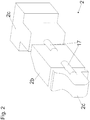
- FIG Figure 2 shows in a perspective schematic view the mold core 2 according to the invention, the in FIG Figure 1 segments 2b and 2c shown are shown in section, so that the connecting means 17, with which the segments 2a, 2b and 2c are connected to one another, can be seen.
- the segment 2c is shown in its entirety. With such segments 2a, 2b, 2c, strong undercuts for the operating fluid tank 1 are possible.
- Fig. 3a the left figure shows schematically how a functional element 7, for example a piezo element, is held by the mold core 2.
- the functional element 7 has holding areas protruding perpendicularly from its longitudinal extent, around which the mold core material is arranged, so that a form-fitting connection is created between the functional element 7 and the mold core 2.
- the mold core 2 is surrounded, for example, in a tool mold 4 with plastic melt 8, for example a thermoplastic. If the plastic melt 8 then hardens, after removal of the mold core material, the dimensionally stable functional element 7 is held in a form-fitting and material-locking manner by the operating fluid tank according to the invention and has access to the interior, for example to record data regarding the content of the operating fluid tank 1.
- the functional element 7 in this case is held by the operating medium tank 1 in such a way that access to the exterior of the operating medium tank 1 also remains, for example to connect a data or control line.
- Figure 3b is shown schematically how a structural feature 10 in the form of a smooth surface of a flat area of a structural element 6, which is held by the mold core 2 while being surrounded by plastic melt 8, is transferred to the inner surface 9 of an operating fluid tank 1 according to the invention made of a thermoplastic material.
- a negative of the surface of the structural element 6 is transferred.
- Figure 3c is shown schematically how a structural element 6, which has a flat area on which structural features 10 are arranged in the form of different rib shapes, transfers to the inner surface 9 of an operating fluid tank 1 according to the invention.
- the structural element 6 is held by the mold core 2 while it is surrounded by plastic melt 8.
- the rib shapes make it possible for the inner surface 9 of the operating fluid tank 1 to have different undercuts, for example, in this area, as a result of which a particularly high level of stability is achieved.
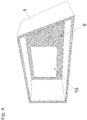
- Fig. 4 shows a schematic perspective view of the interior of an operating fluid tank 1 according to the invention, a region 18 having a smooth surface that was transferred by transferring a structural feature 10 of a structural element 6.
- This surface area represents a smooth negative of the surface area of the structural element 6.
- the area 15 has a rough surface that was created when the mold core 2 was surrounded by plastic melt 8.
- Figure 3b is shown by way of example and schematically how such a structural feature 10 in The form of a smooth surface is transferred to the inner wall of the operating medium tank 1.
- Fig. 5 shows in a schematic representation how a mold core 2 according to the invention is held in a tool mold 4 of a plastic injection molding machine.
- a structural element 6 is glued to the mold core 2 and is thereby held by the mold core 2 while it is surrounded by plastic melt 8.
- a structural element 10 in the form of a smooth surface is thereby transferred to the inner surface 9 of the operating fluid tank 1 according to the invention that is being created.
- the mold core 2 has two holding areas 3 via which the mold core 2 is held in the tool mold 4.
- holding means 16 for example in the form of metal pegs, are arranged on or in the mold core 2.
- the holding means 16 are held in the tool mold 4 by means of clamps 19.
- FIG Figures 6a to 6e various steps of the method according to the invention are shown schematically, with FIG Figure 6a the mold core 2 is held in a tool mold 4 via the holding means 16. The mold 4 is then closed and liquid plastic melt 8 is injected into the mold 4, for example via a plasticizing screw 20 of a plastic injection molding machine.
- This can be a thermoplastic material, for example.
- Figure 6c schematically shows the demolding step in which the blank with the operating fluid tank 1, the holding means and the mold core 2 arranged within the operating fluid tank 1 is removed from the mold 4.
- Fig. 6d is shown schematically how the mold core 2 is rinsed out of the interior of the operating fluid tank 1, for example with water or a solution.
- the mold core material can flow out via the opening 5.
- the finished component is shown schematically in the Figure 6e shown.
- functional elements 7 or transferred structural features 10 are not shown here.
Landscapes
- Engineering & Computer Science (AREA)
- Mechanical Engineering (AREA)
- Manufacturing & Machinery (AREA)
- Chemical & Material Sciences (AREA)
- Materials Engineering (AREA)
- Sustainable Development (AREA)
- Combustion & Propulsion (AREA)
- Transportation (AREA)
- Sustainable Energy (AREA)
- Life Sciences & Earth Sciences (AREA)
- Composite Materials (AREA)
- Moulds For Moulding Plastics Or The Like (AREA)
- Injection Moulding Of Plastics Or The Like (AREA)
Abstract
Description
- Die Erfindung betrifft ein Verfahren zur Herstellung eines Betriebsmitteltanks aus Kunststoff für ein Kraftfahrzeug umfassend das Bereitstellen eines aus einem, vorzugsweise riesel- oder fließfähigen, Formkern-Material hergestellten Formkerns, wobei der Formkern zumindest einen Haltebereich aufweist, über den der Formkern in einer Werkzeugform oder in einer Kunststoffformgebungsmaschine gehalten wird, das Umgeben des Formkerns mit einem Kunststoff, wobei an dem zumindest einen Haltebereich, über den der Formkern in einer Werkzeugform oder einer Kunststoffformgebungsmaschine gehalten wird, zumindest eine Öffnung im Betriebsmitteltank verbleibt, sowie das Entfernen des Formkern-Materials aus dem Betriebsmitteltank über die verbleibende Öffnung.
- Darüber hinaus betrifft die Erfindung einen Formkern zur Herstellung eines Betriebsmitteltanks aus Kunststoff für ein Kraftfahrzeug und einen Betriebsmitteltank für ein Kraftfahrzeug.
- Im Stand der Technik ist es bekannt, Formkerne zur Herstellung von Hohlkörpern aus Kunststoff zu verwenden. Dabei wird zumeist ein riesel- oder fließfähiges Formkern-Material, vorzugsweise ein Granulat, zur Herstellung eines Formkerns verwendet, wobei das Formkern-Material dabei üblicherweise in eine gewisse Form gepresst wird. Anschließend wird der Formkern im Hohlraum einer Werkzeugform oder einer Kunststoffformgebungsmaschine gehalten und mit flüssiger Kunststoff-schmelze umgeben. Nach Druckbeaufschlagung und Aushärten wird der Formkern samt dem Kunststoffmantel entnommen und gegebenenfalls unter Beihilfe eines Lösungsmittels ausgespült, sodass letztlich ein Hohlkörper aus Kunststoff hergestellt ist, dessen Form der Oberfläche des Formkerns entspricht. Ein solcher Formkern ist auch als verlorener Formkern bekannt. Ein derartiger Formkern und ein Verfahren zur Herstellung eines faserverstärkten Strukturhohlbauteils mit einem Formkern ist in der
DE 10 2013 106 876 A1 gezeigt. - Die
WO 2017/148997 betrifft ebenfalls einen Formkern zur Herstellung eines faserverstärkten Hohlbauteils, wobei der Formkern einen Stützkern mit einer zumindest bereichsweise angeordneten Beschichtung aufweist, die ein Expansionsmaterial umfasst. Dabei wird auf den Formkern eine Matrix mit Verstärkungsfasern angeordnet. Anschließend wird der Formkern in ein Formkernwerkzeug verbracht. Die Matrix wird mittels einer Temperatur- und/oder Druckerhöhung ausgehärtet, wobei das Expansionsmaterial bei der Temperatur-erhöhung expandiert und dadurch Verstärkungsfasern an die Innenseite des Formwerkzeugs presst. - Auch die
WO 2017/148998 zeigt ein faserverstärktes Strukturhohlbauteil, wobei im Formkern ein Kanal angeordnet wird, in den Verstärkungsfasern und/oder Matrixmaterial eingebracht werden. Nach dem Aushärten des Matrixmaterials und dem Ausspülen des Formkerns verbleibt das in den Kanal eingebrachte Material als Verstärkungselement, insbesondere als Verstärkungsstrebe im Strukturhohlbauteil. Das Verstärkungselement wird gleichzeitig mit der Oberfläche des Hohlbauteils hergestellt und form- sowie stoffschlüssig mit der Wandung des Strukturhohlbauteils verbunden. - Die
WO 2018/108674 betrifft einen verlorenen Formkern zur Herstellung eines faserverstärkten Bauteils, wobei der Formkern segmentiert ausgebildet ist. Zwischen den Segmenten ist ein elastisches und/oder flexibles Ausgleichselement angeordnet, wodurch ein translatorischer und/oder rotatorischer Versatz zwischen den beiden Segmenten bei der Herstellung des Bauteils ausgleichbar ist. Für die Herstellung können die Verstärkungsfasern mit der Matrix um den verlorenen Formkern angeordnet werden, bevor der Formkern in einem Formwerkzeug ausgehärtet wird. Zudem kann auf einer Außenfläche des Bauteils ein Verstärkungselement aufgepresst werden. Das Verstärkungselement kann gemeinsam mit der Matrix aushärten, sodass sich eine stoffschlüssige Verbindung zwischen dem Verstärkungselement und der Matrix ergibt. Am Verstärkungselement können auch Befestigungsmittel angeordnet sein, beispielsweise ein Gewindeeinsatz, eine Hülse, ein Haken und/oder eine Bohrung. Dadurch kann das Befestigungsmittel mit dem Verstärkungselement in einfacher Weise an der Außenseite am herzustellenden Bauteil angeordnet werden. - Die
JP 2003-291208 JP-H10119055 - Nachteilig am Stand der Technik ist die fehlende Möglichkeit, dass Innere eines mit einem Formkern hergestellten Hohlbauteils zu bearbeiten oder Einlegeteile an vorbestimmten Orten im Inneren des Hohlbauteils anzuordnen und verliersicher dort zu befestigen. Dies betrifft insbesondere Betriebsmitteltanks für Kraftfahrzeuge. Die Aufgabe der Erfindung ist es daher, ein Verfahren zur Verfügung zu stellen, mit dem ein Betriebsmitteltank aus Kunststoff mittels eines Formkerns hergestellt wird, wobei die innere Oberfläche des Betriebsmitteltanks speziell bearbeitet werden soll und/oder ein Einlegeteil an einem vorbestimmten Ort im Inneren im Inneren des Betriebsmitteltanks angeordnet und dort befestigt werden soll.
- Diese Aufgabe wird durch ein Verfahren mit den Merkmalen des Anspruchs 1 und/oder durch ein Verfahren mit den Merkmalen des Anspruchs 2 gelöst. Weitere vorteilhafte Ausführungen der Erfindung sind in den abhängigen Ansprüchen definiert.
- Um einen erfindungsgemäßen Betriebsmitteltank aus Kunststoff für ein Kraftfahrzeug herzustellen, wird zunächst ein, vorzugsweise aus einem riesel- oder fließfähigen Formkern-Material hergestellter, Formkern bereitgestellt. Beispielsweise kann das Formkern-Material ein Bindemittel und/oder ein Granulat umfassen, wobei das Granulat insbesondere einen mineralischen Grundstoff umfassen kann, wie z.B. ein Glas, ein keramisches Material und/oder Sand.
- Der Formkern weist zumindest einen Haltebereich auf, über den der Formkern in einer Werkzeugform oder in einer Kunststoffformgebungsmaschine, beispielsweise einer Spritzgussmaschine, gehalten wird. Derartige Werkzeugformen und Kunststoffformgebungsmaschinen sind prinzipiell im Stand der Technik bekannt. Dabei kann der Haltebereich aus dem gleichen Material wie der restliche Formkern bestehen. Es kann aber auch vorgesehen sein, dass der Haltebereich beispielsweise als metallisches oder keramisches Halteelement ausgebildet ist. Das Halteelement kann mit Befestigungsmitteln, beispielsweise einem Gewinde, versehen sein, mit welchen der Formkern in einer Kunststoffformgebungsmaschine oder einer Werkzeugform gehalten werden kann.
- Je nach Art der Kunststoffformgebungsmaschine oder jener Maschine, von der Kunststoffschmelze in die Werkzeugform eingebracht wird, wird der Formkern mit flüssiger oder pastöser Kunststoffschmelze umgeben. Beispielsweise wird Kunststoffschmelze in eine Werkzeugform oder eine Kunststoffformgebungsmaschine eingebracht, wodurch der Formkern mit Kunststoffschmelze umspritzt und/oder hinterspritzt wird. Dabei können an sich im Stand der Technik bekannte Spritzgussmaschinen verwendet werden, wodurch ein kostengünstiges Herstellungsverfahren realisierbar ist. Am Haltebereich, über den der Formkern in der Werkzeugform oder der Kunststoffformgebungsmaschine gehalten wird, verbleibt eine Öffnung im herzustellenden Betriebsmitteltank, da in diesem Bereich ein Umgeben mit Kunststoffschmelze nicht möglich ist.
- Für die erfindungsgemäßen Verfahren kommen verschiedenste Kunststoffmaterialien in Frage, etwa thermoplastische Kunststoffe wie zum Beispiel Polypropylen (PP), Polyamide (wie etwa Polyamid 6), Polyethylene (wie zum Beispiel quervernetztes (crosslinked) Polyethylen (XPE) oder hochdichtes Polyethylen (HDPE)), Co-Polymere (wie zum Beispiel EthylenVinylalkohol-Co-Polymer (EVOH)). Möglich sind auch Mischungen aus Polypropylen und Polyethylen.
- Möglich ist auch die Verwendung faserverstärkter Kunststoffe, wobei hier alle möglichen Varianten in Frage kommen, wie z. B. Kohlenstofffaser-verstärkte Kunststoffe (CFK) oder Glasfaser-verstärkte Kunststoffe (GFK). In diesem Fall ist es möglich, die Fasern vor dem Umspritzen mit der Kunststoffschmelze am Formkern anzuordnen.
- Nach zumindest teilweisem Aushärten des Kunststoffs wird das Formkernmaterial über die verbleibende Öffnung aus dem Betriebsmitteltank entfernt. Zu diesem Zweck kann es im Falle eines Formkern-Materials mit einem Bindemittel vorteilhaft sein, wenn dieses Bindemittel mittels eines Lösungsmittels löslich ist und dadurch das Formkern-Material einfach aus der Öffnung ausspülbar ist. Ein solches Lösungsmittel kann beispielsweise eine Säure, eine Base, Wasser und/oder einen Alkohol umfassen. Im Falle eines Formkern-Materials ohne Bindemittel kann das Formkern-Material auch einfach mit Wasser oder mit Druckluft aus dem Inneren des Betriebsmitteltanks entfernt werden.
- Erfindungsgemäß ist vorgesehen, dass an einem beschränkten, vom Haltebereich gesonderten Teilbereich des Formkerns ein Strukturelement angeordnet wird, welches während des Umgebens mit flüssiger oder pastöser Kunststoffschmelze vom Formkern gehalten wird. Beim Umgeben mit der Kunststoffschmelze wird eine innere Oberfläche des Betriebsmitteltanks gebildet, auf welche ein auf dem Strukturelement angeordnetes Strukturmerkmal beim Umgeben mit der Kunststoffschmelze während des Aushärtens der Kunststoffschmelze übertragen wird. Das Strukturelement befindet sich dabei zwischen dem Kern und dem Betriebsmitteltank und beeinflusst die Endform des Betriebsmitteltanks auf dessen Innenseite.
- Bei diesem Strukturmerkmal kann es sich beispielsweise um eine geometrische Struktur auf dem Strukturelement handeln, wobei auf der Innenwandung des Betriebsmitteltanks eine Negativform dieser geometrischen Struktur erzeugt wird. Mit dieser Methode können beispielsweise Kanäle auf Bereichen der Innenseite des Betriebsmitteltanks erzeugt werden, wodurch ein besonderes Fließverhalten des Betriebsmittels erwirkt werden kann. In einer Ausführungsform ist das Strukturmerkmal durch eine glatte Oberfläche des Strukturelements gebildet. Bei einer Übertragung dieses Strukturmerkmals auf die innere Oberfläche des Betriebsmitteltanks weist der beim Umgeben mit der Kunststoffschmelze dem Strukturelement gegenüberliegende Bereich eine sehr glatte Innenwandung auf. Eine solche glatte Oberfläche kann in einem Betriebsmitteltank beispielsweise notwendig sein, um als Anlagefläche für einen nachträglich im Betriebsmitteltank angeordneten Flansch zu dienen oder um ein Abperlen von Kraftstoff oder von Ölen, die im Betriebsmitteltank gelagert werden, zu erleichtern. Ein Teilbereich der Innenwandung des Betriebsmitteltanks mit sehr glatter Oberfläche kann auch als Verschleißschutz oder als Lagerfläche für im Inneren des Betriebsmitteltanks angeordnete Bauteile dienen.
- Das Strukturelement kann vorzugsweise aus einem metallischen und/oder keramischen Material bestehen. Für das Strukturelement kommen beispielsweise Einlegeelemente in Frage. Diese Einlegeelemente können die Oberflächenrauigkeit auf der Innenseite des Betriebsmitteltanks beeinflussen und beispielsweise eine besonders glatte innere Oberfläche erzeugen. Je nach Ausbildung des Strukturelements können auf der Innenseite des Betriebsmitteltanks auch Rippen, Schwallwände,Füllkanäle, Dichtflächen oder Gewinde ausgebildet werden. Mit Rippen auf der Innenseite können spezielle Teile des Betriebsmitteltanks verstärkt und stabiler ausgeführt werden. Mit Schwallwänden können größere Verlagerungen des Betriebsmittels während der Bewegung des Fahrzeugs verhindert werden. Dies ist insbesondere für Kraftstofftanks und Motorräder, bei denen hohe Schräglagen auftreten können, relevant. Besonders vorteilhaft ist dabei, dass die Rippen und die Schwallwände integraler Bestandteil des Betriebsmitteltanks sind und gleichzeitig mit dessen Herstellung erstellt werden und aus dem gleichen Material bestehen. Damit können Spannungen im Betriebsmitteltank vermieden oder verringert werden.
- In einer Ausführungsform weist das Strukturelement einen flächigen Bereich auf, auf welchem das oder die Strukturmerkmal(e) angeordnet ist oder sind. Dadurch können flächige Bereich der Innenseite des Betriebsmitteltanks beispielsweise mit einer geometrischen Struktur versehen werden oder besonders glatt ausgebildet werden.
- Nach dem Umgeben mit der Kunststoffschmelze und zumindest teilweisem oder gänzlichem Aushärten der Schmelze wird das Strukturelement gegebenenfalls nach Zerkleinerung des Strukturelements durch die verbleibende Öffnung aus dem Betriebsmitteltank entfernt, vorzugsweise zeitgleich oder nach dem Entfernen des Formkern-Materials. Dies ist möglich, sobald der Betriebsmitteltank zumindest eine gewisse Härte aufweist.
- Erfindungsgemäß ist weiters vorgesehen, dass zusätzlich oder alternativ zur Anordnung eines Strukturelements an einem beschränkten, vom Haltebereich gesonderten, Teilbereich des Formkerns ein formstabiles Funktionselement angeordnet und während des Umgebens mit flüssiger oder pastöser Kunststoffschmelze vom Formkern gehalten wird. Dabei kann das Funktionselement insbesondere form- oder kraftschlüssig vom Formkern gehalten werden. Beim Umgeben mit der Kunststoffschmelze wird eine innere Oberfläche des Betriebsmitteltanks gebildet, mit welcher das Funktionselement beim Umgeben mit der Kunststoffschmelze verbunden wird. Nach Aushärten der Kunststoffschmelze und dem Entfernen des Formkern-Materials aus dem Betriebsmitteltank, was nach zumindest teilweisem oder gänzlichen Aushärten der Kunststoffschmelze möglich ist, ist das Funktionselement mit dem Betriebsmitteltank derart stoffschlüssig und/oder formschlüssig verbunden, dass das Funktionselement Zugang zum Inneren des Betriebsmitteltanks hat.
- Dadurch ist es möglich, dass zumindest eine Seite des Funktionselements auch nach der Verbindung mit dem Betriebsmitteltank frei bleibt und sich die vom Funktionselement zu erfüllende Funktion auf das Innere des Betriebsmitteltanks beziehen kann. Beim Funktionselement kann es sich beispielsweise um ein elektronisches Funktionselement handeln, das einen Sensor und/oder eine Sende- und/oder Empfangseinheit aufweist. Ein solcher Sensor kann beispielsweise den Füllstand des Betriebsmitteltanks oder den Zustand des im Betriebsmitteltank angeordneten Betriebsmittels erfassen und über eine Sendeeinheit weiterleiten, z.B. um eine Warnung im Display des Kraftfahrzeugs anzuzeigen.
- Im Fall eines Sensors kann es sich auch um einen Piezo-Sensor handeln, der über Druckzustände im Inneren des Betriebsmitteltanks Aufschluss gibt. Das Funktionselement kann beispielsweise auch eine Steuer- und/oder Regeleinheit aufweisen, wobei je nach Zustand des Betriebsmittels Steuer- oder Regelungssignale an das Kraftfahrzeug weitergeleitet werden oder solche Signale in Abhängigkeit des Betriebszustands des Fahrzeugs erhalten werden. Das Funktionselement kann beispielsweise auch einen integrierten Temperaturfühler enthalten, der ebenfalls Aufschluss über den Zustand des Betriebsmittels gibt. Das Funktionselement kann zusätzlich oder alternativ auch weitere Sensoren, zum Beispiel für den Füllstand des Betriebsmitteltanks, für den Druck im Betriebsmitteltank, für die Messung des Durchflusses im Betriebsmitteltank und/oder für die Messung des Abstands zu anderen im Betriebsmitteltank angeordneten Gegenständen aufweisen. Es kann sich auch um einen Chip handeln, der die Identifikation von Originalbauteilen ermöglicht. Durch die Anordnung im Inneren des Betriebsmitteltanks ist ein Austauschen des Chips und somit ein Missbrauch praktisch unmöglich. Zudem könnte über eine Sende- und Empfangseinheit ein Auffinden gestohlener Kraftfahrzeuge möglich sein.
- Das Funktionselement kann auch ein Dichtungselement und/oder ein Befestigungselement enthalten. Insbesondere bei einem Kraftstofftank werden im Inneren des Tanks verschiedene Zu- und Ableitungen, beispielsweise für flüssigen Kraftstoff zum Motor oder für verdunsteten Kraftstoff zu einem Aktivkohlefilter, angeordnet. Mit im Inneren des Betriebsmitteltanks bereits an vorbestimmten Stellen angeordneten Dichtungselementen können gas- oder flüssigkeitsdichte Verbindungen mit den Zu- und Ableitungen sichergestellt werden. Bei einem Befestigungselement kann es sich beispielsweise um einen Gewindeeinsatz handeln, mit dem zusätzliche Bauteile im Inneren des Betriebsmitteltanks befestigt werden können. Der Gewindeeinsatz kann aber auch in einem, an den Haltebereich anschließenden Bereich am Formkern angeordnet werden. Über einen solchen Gewindeeinsatz kann es etwa möglich sein, den Betriebsmitteltank als solchen im Kraftfahrzeug zu befestigen.
- Beim Funktionselement kann es sich auch beispielsweise um eine Kabelführung handeln, die im Inneren des Betriebsmitteltanks angeordnet und fest mit dem Betriebsmitteltank verbunden wird. Dadurch ist ein Verrutschen der Kabelführung, insbesondere wenn die Kabel eingezogen werden, unmöglich.
- Als Funktionselement können aber auch verschiedene Einleger, beispielsweise aus Metall, Kunststoff, Keramik oder Hybridmaterial dienen, die verschiedene Funktionen im Inneren des Betriebsmitteltanks erfüllen. Derartige Einleger können beispielsweise Befestigungsmittel sein, mit denen andere nachträglich im Betriebsmitteltank angeordnete Gegenstände befestigt werden können, wie zum Beispiel die Zuleitung zum Vergaser oder auch etwaige Anschlusselemente. Ebenfalls können Einleger als Führungs- und Halteelemente, zum Beispiel für die Kabelführung, dienen. Das Funktionselement kann aber auch als ein Schalter ausgebildet sein, der mit dem erfindungsgemäßen Verfahren im Inneren des Betriebsmitteltanks angeordnet werden kann.
- Das formstabile Funktionselement erfüllt den Zweck, dass es während dem Umgeben mit der Kunststoffschmelze nicht deformiert wird und dadurch nicht in seiner Funktion eingeschränkt wird. Durch die Anordnung und das Halten am Formkern während des Umgebens mit der Kunststoffschmelze wird sichergestellt, dass das Funktionselement oder auch das Strukturelement an dem vorbestimmten Bereich im Inneren des Betriebsmitteltanks platziert wird oder die Strukturmerkmale an dem vorbestimmten Bereich übertragen werden.
- Der erfindungsgemäße Betriebsmitteltank kann ein Kraftstofftank, ein Öltank oder aber auch ein Tank für andere Betriebsmittel wie z.B. Bremsflüssigkeit sein. Nachdem auch Spritzgussmaschinen für das Anordnen von Kunststoffschmelze gemäß dem erfindungsgemäßen Verfahren vorgesehen sind, können gemäß der Erfindung Betriebsmitteltanks spritzgegossen werden. Dabei ist es möglich, im Inneren des spritzgegossenen Betriebsmitteltanks ein Einlegeteil in Form eines formstabilen Funktionselement an einem vorbestimmten Ort zu befestigen oder eine gewünschte Beschaffenheit der inneren Oberfläche an einem vorbestimmten Ort zu erzeugen.
- Ein Betriebsmitteltank, der nach einem der erfindungsgemäßen Verfahren hergestellt wird, hat den Vorteil, dass Strukturelemente im Inneren des Betriebsmitteltanks angeordnet werden können oder Funktionselemente im Inneren des Betriebsmitteltanks ortsfest platziert werden können, ohne dass der Betriebsmitteltank nach der Platzierung des Funktionselements oder der Bearbeitung an der Innenseite im Nachhinein geschlossen werden muss. Es sind somit keine Schweißnähte notwendig. Zudem kann ein solcher Betriebsmitteltank mit einer konstanten und vordefinierten Wandstärke hergestellt werden. Dies ist ein wichtiger Sicherheitsaspekt. Damit ist es nämlich möglich, dass der Betriebsmitteltank eine möglichst geringe, aber aus sicherheitstechnischer Sicht doch ausreichende Wandstärke aufweist. Dadurch sind leichte Betriebsmitteltanks möglich, ohne dass Einbußen in Bezug auf die Sicherheit hingenommen werden müssen.
- Der Formkern kann in einer Ausführungsform über zwei oder mehr Haltebereiche verfügen, über die der Formkern in einer Werkzeugform oder einer Kunststoffformgebungsmaschine, beispielsweise einer Spritzgussmaschine, gehalten wird. Dadurch kann der Formkern stabiler in der Werkzeugform oder der Kunststoffformgebungsmaschine gehalten werden. Zudem ist das Entfernen des Formkern-Materials leichter möglich. Gleichzeitig kann über die Öffnung(en) im Betriebsmitteltank, die in einem oder in mehreren der Haltebereiche verbleiben, Betriebsmittel zu- oder abgeführt werden.
- In einer Ausführungsform der Erfindung wird das Funktionselement und/oder das Strukturelement während des Umgebens mit Kunststoffschmelze vom Formkern formschlüssig gehalten. Zu diesem Zweck kann es beispielsweise vorgesehen sein, dass bestimmte Bereiche des Strukturelements und/oder des Funktionselements als Haltebereiche dienen und das Formkern-Material während der Herstellung des Formkerns um diese Haltebereiche anzuordnen.
- Zusätzlich oder alternativ kann es vorgesehen sein, das Funktionselement und/oder das Strukturelement während des Umgebens mit Kunststoffschmelze vom Formkern kraftschlüssig zu halten. Zu diesem Zweck kann es beispielsweise vorgesehen sein, dass auf dem Strukturelement und/oder dem Funktionselement ein Außengewinde angeordnet ist und der Formkern über eine Ausnehmung mit einem dazu passenden Innengewinde verfügt. Das Funktionselement und/oder das Strukturelement wird dann in diese Ausnehmung angeordnet und mittels der Gewinde gehalten. Dadurch ist ein besonders starker Halt ermöglicht.
- Zusätzlich oder alternativ kann es vorgesehen sein, das Funktionselement und/oder das Strukturelement während des Umgebens mit Kunststoffschmelze stoffschlüssig vom Formkern zu halten. Zu diesem Zweck kann es vorgesehen sein, das Strukturelement und/oder dem Funktionselement mittels eines Klebstoffs auf den Formkern zu kleben.
- Eine form-, kraft- und/oder stoffschlüssige Verbindung ermöglicht eine besonders stabile Verbindung des Formkerns mit dem Funktionselement und/oder dem Strukturelement, sodass die Gefahr des Verrutschens des Funktionselements und/oder des Strukturelements während des Umgebens mit der Kunststoffschmelze verringert wird.
- Es kann vorgesehen sein, dass an dem wenigstens einen Haltebereich ein vorzugsweise metallisches Haltemittel angeordnet ist, mit dem der Formkern in einer Werkzeugform oder einer Kunststoffformgebungsmaschine gehalten wird. Dieses Haltemittel kann beispielsweise ein Außengewinde oder andere Befestigungsmittel aufweisen.
- Der Formkern kann in einer Ausführungsform aus mindestens zwei Segmenten zusammengesetzt sein, wobei jeweils zwei Segmente über ein Verbindungsmittel miteinander verbunden sind. Beim Verbindungsmittel kann es sich beispielsweise um ein elastisches Ausgleichsmittel handeln, um translatorischen oder rotatorischen Versatz zu kompensieren. Das Verbindungsmittel wird nach dem Umgeben mit der Kunststoffschmelze durch die verbleibende Öffnung aus dem Betriebsmitteltank entfernt. Durch einen segmentierten Formkern können auch Geometrien mit Hinterschneidungen einfach realisiert werden.
- Der Formkern kann ein Granulat umfassen, wobei das Granulat aus Sand und/Schaumstoff-Kügelchen bestehen kann. Schaumstoff-Kügelchen bieten den Vorteil eines geringen Gewichts, wodurch die Handhabung des Formkerns erleichtert wird. Für den Formkern kommt insbesondere Sand mit einer Korngröße zwischen 170 und 220 µm in Frage. Als Schaumstoff-Kügelchen kommt beispielsweise ein Standard-Polystyrol-Granulat in Frage mit einer Korngröße zwischen 1 und 5 mm.
- Der Formkern kann in einer Ausführungsform einen Mantel aus einem auflösbaren oder zerkleinerbaren Material aufweisen. Derartige Mäntel für Formkerne sind an sich im Stand der Technik bekannt. Mit einer Mantelfläche kann es möglich sein, auf Bindemittel für den innerhalb des Mantels angeordneten Formkern zu verzichten.
- Der Formkern kann mit einem an sich im Stand der Technik bekannten 3D-Druckverfahren hergestellt werden. Dies bringt insbesondere für die Anordnung des Funktionselements und/oder des Strukturelements Vorteile.
- Die Erfindung betrifft weiters einen Formkern zur Herstellung eines Betriebsmitteltanks aus Kunststoff für ein Kraftfahrzeug gemäß einem der oben beschriebenen Verfahren. Dabei kann der Formkern einen speziell ausgebildeten Bereich aufweisen, in dem das Strukturelement oder das formstabile Funktionselement während des Umgebens mit der Kunststoffschmelze gehalten wird.
- Die Erfindung betrifft weiters einen Betriebsmitteltank für ein Kraftfahrzeug, wobei der Betriebsmitteltank über ein Kunststoff-Spritzgussverfahren hergestellt wird, vorzugsweise nach einem wie oben beschriebenen Verfahren.
- Weitere Vorteile und Einzelheiten der Erfindung werden für verschiedene Ausführungsbeispiele anhand der folgenden Figuren diskutiert. Dabei zeigt:
- Fig. 1
- eine schematische Querschnittsdarstellung eines Betriebsmitteltanks mit darin angeordnetem Formkern,
- Fig. 2
- eine teilweise geschnittene, schematische perspektivische Ansicht eines aus Segmenten zusammengesetzten Formkerns,
- Fig. 3a bis 3c
- schematische Darstellungen zur Anordnung eines Funktionselements im Inneren eines Betriebsmitteltanks sowie zur Übertragung von Strukturelementen auf die innere Oberfläche eines Betriebsmitteltanks,
- Fig. 4
- eine schematische Darstellung eines Innenbereichs eines Betriebsmitteltanks mit übertragenem Strukturmerkmal,
- Fig. 5
- eine schematische Darstellung zur Anordnung eines Formkerns in einer Werkzeugform und
- Fig. 6a bis 6e
- schematische Darstellungen zum erfindungsgemäßen Verfahrensablauf.
- In einer schematischen Querschnittsdarstellung zeigt
Fig. 1 einen aus drei Segmenten 2a, 2b, 2c zusammengesetzten erfindungsgemäßen Formkern 2, wobei die Segmente 2a, 2b, 2c jeweils über ein Verbindungsmittel 17 verbunden sind. An beschränkten Teilbereichen des Formkerns 2 sind ein Strukturelement 6 und ein formstabiles Funktionselement in Form eines Sensors 12 vom Formkern 2 gehalten. Weitere formstabile Funktionselemente, die an beschränkten Teilbereichen des Formkerns 2 gehalten werden, sind ein Befestigungselement 13 in Form eines Gewindes, eine Kabelführung 15 sowie ein allgemeines Funktionselement 7, beispielsweise ein RFID-Chip. Das Strukturelement 6 und die Funktionselemente 7, 12, 13, 15 werden während des Umgebens mit der Kunststoffschmelze 8 vom Formkern 2 gehalten. DieFigur 1 zeigt den Betriebsmitteltank 1 nach zumindest teilweisem Aushärten der Kunststoffschmelze 8 und nach dem Entfernen aus der Werkzeugform 4. In weiterer Folge werden der Formkern 2a, 2b und 2c, die Verbindungsmittel 17 und das Strukturelement 10 aus dem Inneren des Betriebsmitteltanks 1 entfernt. - In der in
Fig. 1 dargestellten Situation ist der erfindungsgemäße Formkern 2 bereits mit einer teilweise ausgehärteten Kunststoffschmelze 8 in Form eines Thermoplasts umgeben. Die Funktionselemente 7, 12, 13 und 15 werden nach Aushärten der Schmelze 8 dabei stoffschlüssig und/oder formschlüssig vom Betriebsmitteltank 1 gehalten. Das Strukturelement 6 weist einen flächigen Bereich mit einem darauf angeordneten Strukturmerkmal 10 auf, beispielsweise eine glatte Oberfläche, welches beim Umgeben mit der Kunststoffschmelze 8 auf die innere Oberfläche 9 des Betriebsmitteltanks 1 übertragen wird. - Die erwähnten beschränkten Teilbereiche sind vom Haltebereich 3, an dem der Formkern 2 in einer Werkzeugform 4 gehalten wird, gesondert. Nach dem Aushärten der Kunststoffschmelze 8 wird das Formkernmaterial über die Öffnung 5, die beim Haltebereich 3 im Betriebsmitteltank 1 verbleibt, entfernt. Auch die Verbindungsmittel 17 und das Strukturelement 6 werden über die verbleibende Öffnung 5 entfernt.
- Insbesondere beim Funktionselement 7 und beim Sensor 12 ist erkennbar, dass diese Elemente in einem hinterschnittenen Bereich des Betriebsmitteltanks 1 angeordnet sind und daher abgesehen von Zugängen zum Inneren und zum Äußeren des Betriebsmitteltanks 1 mit Kunststoffschmelze 8 umgeben sind. Dabei ist beim Sensor 12 ein Bereich auf der Außenseite des Betriebsmitteltanks 1 zugänglich, beispielsweise um eine Daten- oder Steuerleitung anzuschließen. Die Hinterschneidungen sind insbesondere aufgrund der Segmentierung des Formkerns 2 möglich.
-
Figur 2 zeigt in einer perspektivischen schematischen Ansicht den erfindungsgemäßen Formkern 2, wobei die in derFigur 1 gezeigten Segmente 2b und 2c geschnitten dargestellt sind, damit die Verbindungsmittel 17, mit denen die Segmente 2a, 2b und 2c miteinander verbunden sind, erkennbar sind. Das Segment 2c ist in vollständiger Form dargestellt. Mit derartigen Segmenten 2a, 2b, 2c sind starke Hinterschneidungen für den Betriebsmitteltank 1 möglich. - In
Fig. 3a ist auf der linken Abbildung schematisch dargestellt, wie ein Funktionselement 7, beispielsweise ein Piezo-Elements, vom Formkern 2 gehalten wird. Das Funktionslement 7 weist senkrecht von seiner Längserstreckung abstehende Haltebereiche auf, um die das Formkern-Material angeordnet wird, sodass eine formschlüssige Verbindung zwischen Funktionselement 7 und Formkern 2 entsteht. Der Formkern 2 wird beispielsweise in einer Werkzeugform 4 mit Kunststoffschmelze 8, etwa einem Thermoplast, umgeben. Härtet die Kunststoffschmelze 8 dann aus, wird nach Entfernen des Formkernmaterials das formstabile Funktionselement 7 vom erfindungsgemäßen Betriebsmitteltank form- und stoffschlüssig gehalten und hat Zugang zum Inneren, um beispielsweise Daten hinsichtlich des Inhalts des Betriebsmitteltanks 1 zu erfassen. Gleichzeitig wird das Funktionselement 7 in diesem Fall derart vom Betriebsmitteltank 1 gehalten, sodass auch ein Zugang zum Äußeren des Betriebsmitteltanks 1 verbleibt, beispielsweise um eine Daten- oder Steuerleitung anzuschließen. - In
Fig. 3b ist schematisch gezeigt, wie ein Strukturmerkmal 10 in Form einer glatten Oberfläche eines flächigen Bereich eines Strukturelements 6, welches vom Formkern 2 während des Umgebens mit Kunststoffschmelze 8 gehalten wird, auf die innere Oberfläche 9 eines erfindungsgemäßen Betriebsmitteltanks 1 aus einem thermoplastischen Kunststoff übertragen wird. Dabei wird ein Negativ der Oberfläche des Strukturelements 6 übertragen. Nach dem Entfernen des Formkern-Materials verbleibt ein Bereich 18, in dem die innere Oberfläche 9 des Betriebsmitteltanks 1 glatt ist, während die davon abgesehene innere Oberfläche 9 einen Bereich 14 mit rauer Oberfläche ausbildet. - In
Fig. 3c ist schematisch dargestellt, wie ein Strukturelement 6, welches einen flächigen Bereich aufweist, auf dem Strukturmerkmale 10 in Form unterschiedlicher Rippenformen angeordnet sind, auf die innere Oberfläche 9 eines erfindungsgemäßen Betriebsmitteltanks 1 überträgt. Das Strukturelement 6 wird vom Formkern 2 während des Umgebens mit Kunststoffschmelze 8 gehalten. Dadurch entsteht eine Negativ-Form der Rippenformen auf der inneren Oberfläche 9 des Betriebsmitteltanks 1 im Bereich, in dem das Strukturelement 6 vom Formkern 2 während des Umgebens mit der Kunststoffschmelze 8 gehalten wurde. Die Rippenformen ermöglichen es, dass die innere Oberfläche 9 des Betriebsmitteltanks 1 in diesem Bereich beispielsweise unterschiedliche Hinterschneidungen aufweisen kann, wodurch eine besonders hohe Stabilität erreicht wird. -
Fig. 4 zeigt in einer schematischen perspektivischen Ansicht den Innenbereich eines erfindungsgemäßen Betriebsmitteltanks 1, wobei ein Bereich 18 eine glatte Oberfläche aufweist, die durch Übertragung eines Strukturmerkmals 10 eines Strukturelements 6 übertragen wurde. Dieser Oberflächenbereich stellt ein glattes Negativ des Oberflächenbereichs des Strukturelements 6 dar. Der Bereich 15 weist demgegenüber eine raue Oberfläche auf, die beim Umgeben des Formkerns 2 mit Kunststoffschmelze 8 entstanden ist. In derFigur 3b ist beispielhaft und schematisch dargestellt, wie ein solches Strukturmerkmal 10 in Form einer glatten Oberfläche auf die Innenwandung des Betriebsmitteltanks 1 übertragen wird. -
Fig. 5 zeigt in einer schematischen Darstellung, wie ein erfindungsgemäßer Formkern 2 in einer Werkzeugform 4 einer Kunststoffspritzgussmaschine gehalten wird. Ein Strukturelement 6 ist an den Formkern 2 angeklebt und wird dadurch während des Umgebens mit Kunststoffschmelze 8 vom Formkern 2 gehalten. Ein Strukturelement 10 in Form einer glatten Oberfläche wird dadurch auf die innere Oberfläche 9 des entstehenden erfindungsgemäßen Betriebsmitteltanks 1 übertragen. Der Formkern 2 weist zwei Haltebereiche 3 auf, über die der Formkern 2 in der Werkzeugform 4 gehalten wird. Zu diesem Zweck sind Haltemittel 16, beispielsweise in Form von Metallzapfen, am oder im Formkern 2 angeordnet. Die Haltemittel 16 werden über Klammern 19 in der Werkzeugform 4 gehalten. Nach Umgeben des Formkerns 2 mit Kunststoffschmelze 8 und Aushärten,Entfernen des Formkernmaterials sowie Entfernen der Haltemittel 16, verbleiben Öffnungen 5 im Betriebsmitteltank 1. - In den
Fig. 6a bis 6e sind schematisch verschiedene Schritte des erfindungsgemäßen Verfahrens dargestellt, wobei inFig. 6a der Formkern 2 in einer Werkzeugform 4 über die Haltemittel 16 gehalten wird. Anschließend wird die Form 4 geschlossen und flüssige Kunststoffschmelze 8, beispielsweise über eine Plastifizierschnecke 20 einer Kunststoffspritzgussmaschine, in die Form 4 eingespritzt. Dabei kann es sich beispielsweise um ein thermoplastisches Material handeln. - In
Fig. 6b ist gezeigt, wie flüssige Kunststoffschmelze 8 von der Plastifizierschnecke 20 in die Form 4 eingespritzt wird und durch Anordnen im Hohlraum 21 der Formkern 2 mit Kunststoffschmelze 8 umgeben wird. In den Haltebereichen 3, in denen die Haltemittel 16 angeordnet sind, wird keine Kunststoffschmelze 8 angeordnet. Hier verbleiben somit Öffnungen 5 im Betriebsmitteltank 1. -
Fig. 6c zeigt schematisch den Schritt des Entformens, bei dem der Rohling mit dem Betriebsmitteltank 1, den Haltemitteln und dem innerhalb des Betriebsmitteltanks 1 angeordneten Formkern 2 aus der Form 4 entnommen wird. - In
Fig. 6d ist schematisch dargestellt, wie der Formkern 2, beispielsweise mit Wasser oder einer Lösung aus dem Inneren des Betriebsmitteltanks 1 ausgespült wird. Das Formkernmaterial kann dabei über die Öffnung 5 ausfließen. - Das fertige Bauteil ist schematisch in der
Figur 6e gezeigt. Der besseren Übersichtlichkeit halber sind hier Funktionselemente 7 oder übertragene Strukturmerkmale 10 nicht dargestellt. -
- 1
- Betriebsmitteltank
- 2
- Formkern mit Segmenten 2a, 2b, 2c
- 3
- Haltebereich
- 4
- Werkzeugform
- 5
- Öffnung Betriebsmitteltank
- 6
- Strukturelement
- 7
- Funktionselement
- 8
- Kunststoffschmelze
- 9
- innere Oberfläche des Betriebsmitteltanks
- 10
- Strukturmerkmal
- 11
- Betriebsmitteltankinneres
- 12
- Sensor
- 13
- Befestigungselement
- 14
- Bereich mit rauer Oberfläche
- 15
- Kabelführung
- 16
- Haltemittel
- 17
- Verbindungsmittel
- 18
- Bereich mit glatter Oberfläche
- 19
- Klammer
- 20
- Plastifizierschnecke
- 21
- Hohlraum
Claims (15)
- Verfahren zur Herstellung eines Betriebsmitteltanks (1) aus Kunststoff für ein Kraftfahrzeug umfassend folgende Schritte:- Bereitstellen eines aus einem, vorzugsweise riesel- oder fließfähigen, Formkern-Material hergestellten Formkerns (2), wobei der Formkern (2) zumindest einen Haltebereich (3) aufweist, über den der Formkern (2) in einer Werkzeugform (4) oder in einer Kunststoffformgebungsmaschine gehalten wird,- Umgeben des Formkerns (2) mit einer Kunststoffschmelze (8), wobei an dem zumindest einen Haltebereich (3), über den der Formkern (2) in einer Werkzeugform (4) oder einer Kunststoffformgebungsmaschine gehalten wird, zumindest eine Öffnung (5) im Betriebsmitteltank (1) verbleibt,- Entfernen des Formkern-Materials aus dem Betriebsmitteltank (1) über die verbleibende Öffnung (5), dadurch gekennzeichnet, dass
an einem beschränkten, von dem zumindest einen Haltebereich (3) gesonderten Teilbereich des Formkerns (2) ein, vorzugsweise metallisches und/oder keramisches, Strukturelement (6) angeordnet und während des Umgebens mit der Kunststoffschmelze (8) vom Formkern (2) gehalten wird, wobei beim Umgeben mit der Kunststoffschmelze (8) eine innere Oberfläche (9) des Betriebsmitteltanks (1) gebildet wird, auf welche ein auf dem Strukturelement (6) angeordnetes Strukturmerkmal (10) beim Umgeben mit der Kunststoffschmelze (8) übertragen wird und wobei das Strukturelement (6) nach zumindest teilweisem Aushärten der Kunststoffschmelze (8) durch die verbleibende Öffnung (5) aus dem Betriebsmitteltank (1) entfernt wird. - Verfahren zur Herstellung eines Betriebsmitteltanks (1) aus Kunststoff für ein Kraftfahrzeug umfassend folgende Schritte:- Bereitstellen eines aus einem, vorzugsweise riesel- oder fließfähigen, Formkern-Material hergestellten Formkerns (2), wobei der Formkern (2) zumindest einen Haltebereich (3) aufweist, über den der Formkern (2) in einer Werkzeugform (4) oder einer Kunststoffformgebungsmaschine gehalten wird,- Umgeben des Formkerns (2) mit einer Kunststoffschmelze (8), wobei an dem zumindest einen Haltebereich (3), über den der Formkern (2) in einer Werkzeugform (4) oder einer Kunststoffformgebungsmaschine gehalten wird, zumindest eine Öffnung (5) im Betriebsmitteltank (1) verbleibt,- Entfernen des Formkern-Materials aus dem Betriebsmitteltank (1) über die verbleibende Öffnung (5), dadurch gekennzeichnet, dass
an einem beschränkten, von dem zumindest einen Haltebereich (3) gesonderten Teilbereich des Formkerns (2) ein formstabiles Funktionselement (7) angeordnet und während des Umgebens mit der Kunststoffschmelze (8) vom Formkern (2) gehalten wird, wobei beim Umgeben mit der Kunststoffschmelze (8) eine innere Oberfläche (9) des Betriebsmitteltanks (1) gebildet wird, mit welcher das Funktionselement (7) beim Umgeben mit der Kunststoffschmelze (8) verbunden wird und wobei das Funktionselement (7) nach Aushärten der Kunststoffschmelze (8) und dem Entfernen des Formkern-Materials vom Betriebsmitteltank (1) derart stoffschlüssig und/oder formschlüssig gehalten wird, dass das Funktionselement (7) Zugang zum Inneren des Betriebsmitteltanks (1) hat. - Verfahren nach Anspruch 1, wobei das Strukturmerkmal (10) durch eine glatte Oberfläche des Strukturelements (6) gebildet ist.
- Verfahren nach Anspruch 1 oder 3, wobei das Strukturelement (6) einen flächigen Bereich aufweist, auf welchem das Strukturmerkmal (10) angeordnet ist.
- Verfahren nach Anspruch 2, wobei das Funktionselement (7) eine elektronisches Funktionselement, vorzugsweise einen Sensor (12) und/oder eine Sende-Empfangseinheit enthält.
- Verfahren nach Anspruch 2 oder 5, wobei das Funktionselement (7) ein Dichtungselement (13) und/oder ein Befestigungselement (14) enthält.
- Verfahren nach einem der Ansprüche 1 bis 6, wobei das Funktionselement (7) und/oder das Strukturelement (10) formschlüssig und/oder kraftschlüssig und/oder stoffschlüssig vom Formkern (2) während des Umgebens mit Kunststoffschmelze (8) gehalten wird.
- Verfahren nach einem der Ansprüche 1 bis 7, wobei der Formkern (2) zwei Haltebereiche (3) aufweist, über die der Formkern (2) in einer Werkzeugform (4) oder einer Kunststoffformgebungsmaschine gehalten wird.
- Verfahren nach einem der Ansprüche 1 bis 8, wobei an dem wenigstens einen Haltebereich (3) ein, vorzugsweise metallisches, Haltemittel (16) angeordnet ist, mit dem der Formkern (2) in einer Werkzeugform (4) oder einer Kunststoffformgebungsmaschine gehalten wird.
- Verfahren nach einem der Ansprüche 1 bis 9, wobei der Formkern (2) aus mindestens zwei Segmenten (2a, 2b, 2c) zusammengesetzt ist, wobei jeweils zwei Segmente (2a, 2b, 2c) über Verbindungsmittel (17) miteinander verbunden sind und wobei das oder die Verbindungsmittel (17) nach dem Umgeben mit der Kunststoffschmelze (8) durch die verbleibende Öffnung (5) aus dem Betriebsmitteltank (1) entfernt wird oder werden.
- Verfahren nach einem der Ansprüche 1 bis 10, wobei der Formkern (2) aus Sand oder Schaumstoff-Kügelchen besteht.
- Verfahren nach Anspruch 11, wobei der Formkern (2) einen Mantel aus einem auflösbaren oder zerkleinerbaren Material aufweist.
- Verfahren nach einem der Ansprüche 1 bis 12, wobei der Formkern mittels eines 3D-Druckverfahrens hergestellt wird.
- Formkern (2) zur Herstellung eines Betriebsmitteltanks (1) aus Kunststoff für ein Kraftfahrzeug gemäß einem Verfahren nach einem der Ansprüche 1 bis 13.
- Betriebsmitteltank (1) für ein Kraftfahrzeug, insbesondere hergestellt gemäß einem Verfahren nach einem der Ansprüche 1 bis 13, dadurch gekennzeichnet, dass der Betriebsmitteltank (1)aus einem Kunststoff spritzgegossen ist.
Applications Claiming Priority (1)
| Application Number | Priority Date | Filing Date | Title |
|---|---|---|---|
| ATA50758/2019A AT522894B1 (de) | 2019-08-30 | 2019-08-30 | Verfahren zur Herstellung eines Betriebsmitteltanks |
Publications (2)
| Publication Number | Publication Date |
|---|---|
| EP3785874A1 true EP3785874A1 (de) | 2021-03-03 |
| EP3785874B1 EP3785874B1 (de) | 2022-11-02 |
Family
ID=72422048
Family Applications (1)
| Application Number | Title | Priority Date | Filing Date |
|---|---|---|---|
| EP20193297.7A Active EP3785874B1 (de) | 2019-08-30 | 2020-08-28 | Verfahren zur herstellung eines betriebsmitteltanks |
Country Status (6)
| Country | Link |
|---|---|
| US (1) | US20210060827A1 (de) |
| EP (1) | EP3785874B1 (de) |
| JP (1) | JP7026743B2 (de) |
| AT (1) | AT522894B1 (de) |
| BR (1) | BR102020017621A2 (de) |
| ES (1) | ES2937859T3 (de) |
Citations (8)
| Publication number | Priority date | Publication date | Assignee | Title |
|---|---|---|---|---|
| DE19530254A1 (de) * | 1995-08-17 | 1997-02-20 | Gerhard Dr Ing Betz | Verfahren zur Erzeugung von Hohlräumen in Gußteilen und Form (Teil II) |
| JPH10119055A (ja) | 1996-10-18 | 1998-05-12 | Toyota Motor Corp | 樹脂中空品の製造方法およびそれに用いる消失性中子 |
| JP2003291208A (ja) | 2002-04-04 | 2003-10-14 | Toyota Motor Corp | 樹脂中空成形品の製造方法 |
| EP2733321A1 (de) * | 2012-08-28 | 2014-05-21 | Yapp Automotive Parts Co., Ltd. | Harnstofftank für kraftfahrzeug und verfahren zu seiner herstellung |
| DE102013106876A1 (de) | 2013-07-01 | 2015-01-08 | C.F. Maier GmbH & Co. KG | Formkern und Verfahren zum Herstellen von faserverstärkten Strukturhohlbauteilen |
| WO2017148997A1 (de) | 2016-03-04 | 2017-09-08 | KTM Technologies GmbH | Formkern mit expansionsmaterial |
| WO2017148998A1 (de) | 2016-03-04 | 2017-09-08 | KTM Technologies GmbH | Verfahren zur herstellung eines faserverstärkten strukturhohlbauteils sowie strukturhohlbauteil |
| WO2018108674A2 (de) | 2016-12-12 | 2018-06-21 | Ktm-Technologies Gmbh | Verlorener formkern sowie ein verfahren zur herstellung eines bauteils und das bauteil selbst |
Family Cites Families (12)
| Publication number | Priority date | Publication date | Assignee | Title |
|---|---|---|---|---|
| JPS5995130A (ja) * | 1982-11-22 | 1984-06-01 | Hitachi Plant Eng & Constr Co Ltd | 中空ダイヤフラムの製造方法 |
| JPH085062B2 (ja) * | 1987-03-24 | 1996-01-24 | カルソニック株式会社 | 樹脂成形用中子 |
| JPH02124122U (de) * | 1989-03-24 | 1990-10-12 | ||
| JPH11148851A (ja) * | 1997-05-12 | 1999-06-02 | Denso Corp | 給油燃料計測装置、燃料残量計測装置、および蒸発燃料処理装置 |
| JP3862948B2 (ja) * | 2000-11-24 | 2006-12-27 | 株式会社荏原製作所 | 成形品の3次元形状成形方法及び成形装置 |
| US20060019551A1 (en) * | 2004-07-21 | 2006-01-26 | Jamnia Mohammad A | Method of manufacturing a product having encapsulated electronic components |
| JP4715634B2 (ja) * | 2006-05-24 | 2011-07-06 | 株式会社デンソー | 電気装置およびその製造方法 |
| EP2857245A1 (de) * | 2013-10-03 | 2015-04-08 | Inergy Automotive Systems Research (Société Anonyme) | Behälter mit innerem Verbindungsteil und Verfahren zur Montage eines solchen Behälters |
| JP2016000514A (ja) * | 2014-05-20 | 2016-01-07 | 早川ゴム株式会社 | 中空状ゴム成形体及びその製造方法 |
| JP6750962B2 (ja) * | 2016-05-09 | 2020-09-02 | ポリプラスチックス株式会社 | インサート成形体、及び燃料ポンプ用電気接続コネクタ |
| EP3635347B1 (de) * | 2017-06-07 | 2021-12-22 | Stratosphere, S.A. | Kraftstofftank mit integrierten füllstandsensoren, insbesondere für luftfahrzeuge |
| JP6749291B2 (ja) * | 2017-07-18 | 2020-09-02 | 愛三工業株式会社 | 蒸発燃料処理装置の漏れ検出装置 |
-
2019
- 2019-08-30 AT ATA50758/2019A patent/AT522894B1/de active
-
2020
- 2020-08-27 US US17/004,757 patent/US20210060827A1/en active Pending
- 2020-08-28 ES ES20193297T patent/ES2937859T3/es active Active
- 2020-08-28 EP EP20193297.7A patent/EP3785874B1/de active Active
- 2020-08-28 JP JP2020144143A patent/JP7026743B2/ja active Active
- 2020-08-28 BR BR102020017621-8A patent/BR102020017621A2/pt unknown
Patent Citations (8)
| Publication number | Priority date | Publication date | Assignee | Title |
|---|---|---|---|---|
| DE19530254A1 (de) * | 1995-08-17 | 1997-02-20 | Gerhard Dr Ing Betz | Verfahren zur Erzeugung von Hohlräumen in Gußteilen und Form (Teil II) |
| JPH10119055A (ja) | 1996-10-18 | 1998-05-12 | Toyota Motor Corp | 樹脂中空品の製造方法およびそれに用いる消失性中子 |
| JP2003291208A (ja) | 2002-04-04 | 2003-10-14 | Toyota Motor Corp | 樹脂中空成形品の製造方法 |
| EP2733321A1 (de) * | 2012-08-28 | 2014-05-21 | Yapp Automotive Parts Co., Ltd. | Harnstofftank für kraftfahrzeug und verfahren zu seiner herstellung |
| DE102013106876A1 (de) | 2013-07-01 | 2015-01-08 | C.F. Maier GmbH & Co. KG | Formkern und Verfahren zum Herstellen von faserverstärkten Strukturhohlbauteilen |
| WO2017148997A1 (de) | 2016-03-04 | 2017-09-08 | KTM Technologies GmbH | Formkern mit expansionsmaterial |
| WO2017148998A1 (de) | 2016-03-04 | 2017-09-08 | KTM Technologies GmbH | Verfahren zur herstellung eines faserverstärkten strukturhohlbauteils sowie strukturhohlbauteil |
| WO2018108674A2 (de) | 2016-12-12 | 2018-06-21 | Ktm-Technologies Gmbh | Verlorener formkern sowie ein verfahren zur herstellung eines bauteils und das bauteil selbst |
Also Published As
| Publication number | Publication date |
|---|---|
| ES2937859T3 (es) | 2023-03-31 |
| JP7026743B2 (ja) | 2022-02-28 |
| EP3785874B1 (de) | 2022-11-02 |
| AT522894B1 (de) | 2022-02-15 |
| JP2021037755A (ja) | 2021-03-11 |
| US20210060827A1 (en) | 2021-03-04 |
| BR102020017621A2 (pt) | 2021-04-20 |
| AT522894A1 (de) | 2021-03-15 |
Similar Documents
| Publication | Publication Date | Title |
|---|---|---|
| DE102009006066B4 (de) | Form und Verfahren für die Herstellung zweifarbiger Spritzgussteile | |
| DE102014004157B4 (de) | Verfahren zur Herstellung von Lasteinleitungs-Flanschen an faserverstärkten Hohlprofilen mit thermoplastischer Matrix | |
| EP3490776B1 (de) | Verfahren zum herstellen eines flüssigkeitsbehälters, flüssigkeitsbehälter für ein kraftfahrzeug und spritzgusswerkzeug | |
| EP3389978B1 (de) | Verfahren zur herstellung eines rohres sowie spritzgiessvorrichtung | |
| WO2011072935A1 (de) | Spritzgiessverfahren zur herstellung eines funktionsteils mit einer aussparung | |
| EP0635672A1 (de) | Druckbehälter, insbesondere Druckspeicherbehälter, Verfahren zu ihrer Herstellung und Kunststoffe hierfür | |
| EP0927310A1 (de) | Kugelgelenk und verfahren zu seiner herstellung | |
| DE102013215067A1 (de) | Betätigungspedal, insbesondere für ein Kraftfahrzeug | |
| DE102013009931A1 (de) | Verfahren und Werkzeug zum Herstellen eines Faserverbundbauteils | |
| DE102011106700A1 (de) | Bauteil, insbesondere für einen Kraftwagen | |
| EP3785874B1 (de) | Verfahren zur herstellung eines betriebsmitteltanks | |
| DE102012001076A1 (de) | Verfahren zur Erhöhung einer Dauerfestigkeit eines Hohlkörpers und dazugehörigen Hohlkörper | |
| DE102017211625A1 (de) | Verfahren zur Herstellung einer Lagerbuchse, Lagerbuchse sowie Lenker für eine Radaufhängung eines Kraftfahrzeuges | |
| EP3666496B1 (de) | Verfahren zur herstellung eines kunststofftanks | |
| DE102017211419A1 (de) | Verfahren zur Herstellung eines faserverstärkten Bauteils für ein Kraftfahrzeug und faserverstärktes Bauteil | |
| DE102010050221A1 (de) | Langfaserverstärkte Gewindebuchse aus Thermoplast-Kunststoff | |
| DE102013019470A1 (de) | Strukturbauteil mit einer Hohlstruktur | |
| EP1005408B1 (de) | Verfahren und justierdüse zum spritzgiessen von spritzgussteilen aus plastifizierbarem material | |
| DE102015222298A1 (de) | Verfahren zur Herstellung eines Fahrzeugbauteils | |
| DE102021205347B3 (de) | Elastomerverbundlager, Lageranordnung und Verfahren zur Herstellung einer Außenhülse eines Elastomerverbundlagers | |
| DE102012213666A1 (de) | Pedal für ein Kraftfahrzeug | |
| EP3822062B1 (de) | Kunststofftank und verfahren zur herstellung eines kunststofftanks | |
| EP3488988A1 (de) | Verfahren zum herstellen eines kraftstofftanks, kraftstofftank sowie verwendung von polyamid 6 | |
| WO2019048141A1 (de) | Smc-werkzeug, verfahren zur herstellung eines smc-bauteils und smc-bauteil | |
| DE102013020872B4 (de) | Verfahren zur Herstellung eines faserverstärkten Kunststoffbauteils mit einer Hohlstruktur |
Legal Events
| Date | Code | Title | Description |
|---|---|---|---|
| PUAI | Public reference made under article 153(3) epc to a published international application that has entered the european phase |
Free format text: ORIGINAL CODE: 0009012 |
|
| STAA | Information on the status of an ep patent application or granted ep patent |
Free format text: STATUS: THE APPLICATION HAS BEEN PUBLISHED |
|
| AK | Designated contracting states |
Kind code of ref document: A1 Designated state(s): AL AT BE BG CH CY CZ DE DK EE ES FI FR GB GR HR HU IE IS IT LI LT LU LV MC MK MT NL NO PL PT RO RS SE SI SK SM TR |
|
| AX | Request for extension of the european patent |
Extension state: BA ME |
|
| STAA | Information on the status of an ep patent application or granted ep patent |
Free format text: STATUS: REQUEST FOR EXAMINATION WAS MADE |
|
| 17P | Request for examination filed |
Effective date: 20210803 |
|
| RBV | Designated contracting states (corrected) |
Designated state(s): AL AT BE BG CH CY CZ DE DK EE ES FI FR GB GR HR HU IE IS IT LI LT LU LV MC MK MT NL NO PL PT RO RS SE SI SK SM TR |
|
| GRAP | Despatch of communication of intention to grant a patent |
Free format text: ORIGINAL CODE: EPIDOSNIGR1 |
|
| STAA | Information on the status of an ep patent application or granted ep patent |
Free format text: STATUS: GRANT OF PATENT IS INTENDED |
|
| INTG | Intention to grant announced |
Effective date: 20220602 |
|
| GRAS | Grant fee paid |
Free format text: ORIGINAL CODE: EPIDOSNIGR3 |
|
| GRAA | (expected) grant |
Free format text: ORIGINAL CODE: 0009210 |
|
| STAA | Information on the status of an ep patent application or granted ep patent |
Free format text: STATUS: THE PATENT HAS BEEN GRANTED |
|
| RAP3 | Party data changed (applicant data changed or rights of an application transferred) |
Owner name: KTM AG |
|
| AK | Designated contracting states |
Kind code of ref document: B1 Designated state(s): AL AT BE BG CH CY CZ DE DK EE ES FI FR GB GR HR HU IE IS IT LI LT LU LV MC MK MT NL NO PL PT RO RS SE SI SK SM TR |
|
| REG | Reference to a national code |
Ref country code: GB Ref legal event code: FG4D Free format text: NOT ENGLISH |
|
| REG | Reference to a national code |
Ref country code: CH Ref legal event code: EP Ref country code: AT Ref legal event code: REF Ref document number: 1528440 Country of ref document: AT Kind code of ref document: T Effective date: 20221115 |
|
| REG | Reference to a national code |
Ref country code: DE Ref legal event code: R096 Ref document number: 502020001920 Country of ref document: DE |
|
| REG | Reference to a national code |
Ref country code: IE Ref legal event code: FG4D Free format text: LANGUAGE OF EP DOCUMENT: GERMAN |
|
| REG | Reference to a national code |
Ref country code: LT Ref legal event code: MG9D |
|
| REG | Reference to a national code |
Ref country code: NL Ref legal event code: MP Effective date: 20221102 |
|
| REG | Reference to a national code |
Ref country code: ES Ref legal event code: FG2A Ref document number: 2937859 Country of ref document: ES Kind code of ref document: T3 Effective date: 20230331 |
|
| PG25 | Lapsed in a contracting state [announced via postgrant information from national office to epo] |
Ref country code: SE Free format text: LAPSE BECAUSE OF FAILURE TO SUBMIT A TRANSLATION OF THE DESCRIPTION OR TO PAY THE FEE WITHIN THE PRESCRIBED TIME-LIMIT Effective date: 20221102 Ref country code: PT Free format text: LAPSE BECAUSE OF FAILURE TO SUBMIT A TRANSLATION OF THE DESCRIPTION OR TO PAY THE FEE WITHIN THE PRESCRIBED TIME-LIMIT Effective date: 20230302 Ref country code: NO Free format text: LAPSE BECAUSE OF FAILURE TO SUBMIT A TRANSLATION OF THE DESCRIPTION OR TO PAY THE FEE WITHIN THE PRESCRIBED TIME-LIMIT Effective date: 20230202 Ref country code: LT Free format text: LAPSE BECAUSE OF FAILURE TO SUBMIT A TRANSLATION OF THE DESCRIPTION OR TO PAY THE FEE WITHIN THE PRESCRIBED TIME-LIMIT Effective date: 20221102 Ref country code: FI Free format text: LAPSE BECAUSE OF FAILURE TO SUBMIT A TRANSLATION OF THE DESCRIPTION OR TO PAY THE FEE WITHIN THE PRESCRIBED TIME-LIMIT Effective date: 20221102 |
|
| PG25 | Lapsed in a contracting state [announced via postgrant information from national office to epo] |
Ref country code: RS Free format text: LAPSE BECAUSE OF FAILURE TO SUBMIT A TRANSLATION OF THE DESCRIPTION OR TO PAY THE FEE WITHIN THE PRESCRIBED TIME-LIMIT Effective date: 20221102 Ref country code: PL Free format text: LAPSE BECAUSE OF FAILURE TO SUBMIT A TRANSLATION OF THE DESCRIPTION OR TO PAY THE FEE WITHIN THE PRESCRIBED TIME-LIMIT Effective date: 20221102 Ref country code: LV Free format text: LAPSE BECAUSE OF FAILURE TO SUBMIT A TRANSLATION OF THE DESCRIPTION OR TO PAY THE FEE WITHIN THE PRESCRIBED TIME-LIMIT Effective date: 20221102 Ref country code: IS Free format text: LAPSE BECAUSE OF FAILURE TO SUBMIT A TRANSLATION OF THE DESCRIPTION OR TO PAY THE FEE WITHIN THE PRESCRIBED TIME-LIMIT Effective date: 20230302 Ref country code: HR Free format text: LAPSE BECAUSE OF FAILURE TO SUBMIT A TRANSLATION OF THE DESCRIPTION OR TO PAY THE FEE WITHIN THE PRESCRIBED TIME-LIMIT Effective date: 20221102 Ref country code: GR Free format text: LAPSE BECAUSE OF FAILURE TO SUBMIT A TRANSLATION OF THE DESCRIPTION OR TO PAY THE FEE WITHIN THE PRESCRIBED TIME-LIMIT Effective date: 20230203 |
|
| PG25 | Lapsed in a contracting state [announced via postgrant information from national office to epo] |
Ref country code: NL Free format text: LAPSE BECAUSE OF FAILURE TO SUBMIT A TRANSLATION OF THE DESCRIPTION OR TO PAY THE FEE WITHIN THE PRESCRIBED TIME-LIMIT Effective date: 20221102 |
|
| P01 | Opt-out of the competence of the unified patent court (upc) registered |
Effective date: 20230601 |
|
| PG25 | Lapsed in a contracting state [announced via postgrant information from national office to epo] |
Ref country code: SM Free format text: LAPSE BECAUSE OF FAILURE TO SUBMIT A TRANSLATION OF THE DESCRIPTION OR TO PAY THE FEE WITHIN THE PRESCRIBED TIME-LIMIT Effective date: 20221102 Ref country code: RO Free format text: LAPSE BECAUSE OF FAILURE TO SUBMIT A TRANSLATION OF THE DESCRIPTION OR TO PAY THE FEE WITHIN THE PRESCRIBED TIME-LIMIT Effective date: 20221102 Ref country code: EE Free format text: LAPSE BECAUSE OF FAILURE TO SUBMIT A TRANSLATION OF THE DESCRIPTION OR TO PAY THE FEE WITHIN THE PRESCRIBED TIME-LIMIT Effective date: 20221102 Ref country code: DK Free format text: LAPSE BECAUSE OF FAILURE TO SUBMIT A TRANSLATION OF THE DESCRIPTION OR TO PAY THE FEE WITHIN THE PRESCRIBED TIME-LIMIT Effective date: 20221102 Ref country code: CZ Free format text: LAPSE BECAUSE OF FAILURE TO SUBMIT A TRANSLATION OF THE DESCRIPTION OR TO PAY THE FEE WITHIN THE PRESCRIBED TIME-LIMIT Effective date: 20221102 |
|
| REG | Reference to a national code |
Ref country code: DE Ref legal event code: R097 Ref document number: 502020001920 Country of ref document: DE |
|
| PG25 | Lapsed in a contracting state [announced via postgrant information from national office to epo] |
Ref country code: SK Free format text: LAPSE BECAUSE OF FAILURE TO SUBMIT A TRANSLATION OF THE DESCRIPTION OR TO PAY THE FEE WITHIN THE PRESCRIBED TIME-LIMIT Effective date: 20221102 Ref country code: AL Free format text: LAPSE BECAUSE OF FAILURE TO SUBMIT A TRANSLATION OF THE DESCRIPTION OR TO PAY THE FEE WITHIN THE PRESCRIBED TIME-LIMIT Effective date: 20221102 |
|
| PLBE | No opposition filed within time limit |
Free format text: ORIGINAL CODE: 0009261 |
|
| STAA | Information on the status of an ep patent application or granted ep patent |
Free format text: STATUS: NO OPPOSITION FILED WITHIN TIME LIMIT |
|
| 26N | No opposition filed |
Effective date: 20230803 |
|
| PGFP | Annual fee paid to national office [announced via postgrant information from national office to epo] |
Ref country code: IT Payment date: 20230831 Year of fee payment: 4 Ref country code: ES Payment date: 20230913 Year of fee payment: 4 |
|
| PG25 | Lapsed in a contracting state [announced via postgrant information from national office to epo] |
Ref country code: SI Free format text: LAPSE BECAUSE OF FAILURE TO SUBMIT A TRANSLATION OF THE DESCRIPTION OR TO PAY THE FEE WITHIN THE PRESCRIBED TIME-LIMIT Effective date: 20221102 |
|
| PGFP | Annual fee paid to national office [announced via postgrant information from national office to epo] |
Ref country code: FR Payment date: 20230725 Year of fee payment: 4 Ref country code: DE Payment date: 20230830 Year of fee payment: 4 |
|
| PG25 | Lapsed in a contracting state [announced via postgrant information from national office to epo] |
Ref country code: MC Free format text: LAPSE BECAUSE OF FAILURE TO SUBMIT A TRANSLATION OF THE DESCRIPTION OR TO PAY THE FEE WITHIN THE PRESCRIBED TIME-LIMIT Effective date: 20221102 |
|
| REG | Reference to a national code |
Ref country code: CH Ref legal event code: PL |
|
| PG25 | Lapsed in a contracting state [announced via postgrant information from national office to epo] |
Ref country code: MC Free format text: LAPSE BECAUSE OF FAILURE TO SUBMIT A TRANSLATION OF THE DESCRIPTION OR TO PAY THE FEE WITHIN THE PRESCRIBED TIME-LIMIT Effective date: 20221102 |
|
| PG25 | Lapsed in a contracting state [announced via postgrant information from national office to epo] |
Ref country code: LU Free format text: LAPSE BECAUSE OF NON-PAYMENT OF DUE FEES Effective date: 20230828 |
|
| PG25 | Lapsed in a contracting state [announced via postgrant information from national office to epo] |
Ref country code: LU Free format text: LAPSE BECAUSE OF NON-PAYMENT OF DUE FEES Effective date: 20230828 Ref country code: CH Free format text: LAPSE BECAUSE OF NON-PAYMENT OF DUE FEES Effective date: 20230831 |
|
| REG | Reference to a national code |
Ref country code: BE Ref legal event code: MM Effective date: 20230831 |
|
| REG | Reference to a national code |
Ref country code: IE Ref legal event code: MM4A |