EP3785766A1 - Particle beam therapy system, particle beam therapy system construction method, and particle beam therapy apparatus - Google Patents
Particle beam therapy system, particle beam therapy system construction method, and particle beam therapy apparatus Download PDFInfo
- Publication number
- EP3785766A1 EP3785766A1 EP19792446.7A EP19792446A EP3785766A1 EP 3785766 A1 EP3785766 A1 EP 3785766A1 EP 19792446 A EP19792446 A EP 19792446A EP 3785766 A1 EP3785766 A1 EP 3785766A1
- Authority
- EP
- European Patent Office
- Prior art keywords
- particle beam
- therapy system
- transportation line
- specific portion
- beam therapy
- Prior art date
- Legal status (The legal status is an assumption and is not a legal conclusion. Google has not performed a legal analysis and makes no representation as to the accuracy of the status listed.)
- Pending
Links
Images


Classifications
-
- A—HUMAN NECESSITIES
- A61—MEDICAL OR VETERINARY SCIENCE; HYGIENE
- A61N—ELECTROTHERAPY; MAGNETOTHERAPY; RADIATION THERAPY; ULTRASOUND THERAPY
- A61N5/00—Radiation therapy
- A61N5/10—X-ray therapy; Gamma-ray therapy; Particle-irradiation therapy
- A61N5/1048—Monitoring, verifying, controlling systems and methods
- A61N5/1049—Monitoring, verifying, controlling systems and methods for verifying the position of the patient with respect to the radiation beam
-
- A—HUMAN NECESSITIES
- A61—MEDICAL OR VETERINARY SCIENCE; HYGIENE
- A61N—ELECTROTHERAPY; MAGNETOTHERAPY; RADIATION THERAPY; ULTRASOUND THERAPY
- A61N5/00—Radiation therapy
- A61N5/10—X-ray therapy; Gamma-ray therapy; Particle-irradiation therapy
- A61N5/1077—Beam delivery systems
- A61N5/1079—Sharing a beam by multiple treatment stations
-
- A—HUMAN NECESSITIES
- A61—MEDICAL OR VETERINARY SCIENCE; HYGIENE
- A61N—ELECTROTHERAPY; MAGNETOTHERAPY; RADIATION THERAPY; ULTRASOUND THERAPY
- A61N5/00—Radiation therapy
- A61N5/10—X-ray therapy; Gamma-ray therapy; Particle-irradiation therapy
- A61N5/1077—Beam delivery systems
- A61N5/1081—Rotating beam systems with a specific mechanical construction, e.g. gantries
-
- G—PHYSICS
- G21—NUCLEAR PHYSICS; NUCLEAR ENGINEERING
- G21F—PROTECTION AGAINST X-RADIATION, GAMMA RADIATION, CORPUSCULAR RADIATION OR PARTICLE BOMBARDMENT; TREATING RADIOACTIVELY CONTAMINATED MATERIAL; DECONTAMINATION ARRANGEMENTS THEREFOR
- G21F7/00—Shielded cells or rooms
-
- G—PHYSICS
- G21—NUCLEAR PHYSICS; NUCLEAR ENGINEERING
- G21F—PROTECTION AGAINST X-RADIATION, GAMMA RADIATION, CORPUSCULAR RADIATION OR PARTICLE BOMBARDMENT; TREATING RADIOACTIVELY CONTAMINATED MATERIAL; DECONTAMINATION ARRANGEMENTS THEREFOR
- G21F7/00—Shielded cells or rooms
- G21F7/005—Shielded passages through walls; Locks; Transferring devices between rooms
-
- A—HUMAN NECESSITIES
- A61—MEDICAL OR VETERINARY SCIENCE; HYGIENE
- A61N—ELECTROTHERAPY; MAGNETOTHERAPY; RADIATION THERAPY; ULTRASOUND THERAPY
- A61N5/00—Radiation therapy
- A61N5/10—X-ray therapy; Gamma-ray therapy; Particle-irradiation therapy
- A61N2005/1085—X-ray therapy; Gamma-ray therapy; Particle-irradiation therapy characterised by the type of particles applied to the patient
- A61N2005/1087—Ions; Protons
-
- A—HUMAN NECESSITIES
- A61—MEDICAL OR VETERINARY SCIENCE; HYGIENE
- A61N—ELECTROTHERAPY; MAGNETOTHERAPY; RADIATION THERAPY; ULTRASOUND THERAPY
- A61N5/00—Radiation therapy
- A61N5/10—X-ray therapy; Gamma-ray therapy; Particle-irradiation therapy
- A61N2005/1092—Details
- A61N2005/1094—Shielding, protecting against radiation
Definitions
- Embodiments of the present invention relate to a particle beam therapy system, a particle beam therapy system construction method, and a particle beam therapy apparatus.
- a conventional particle beam therapy system therapy is performed by irradiating a lesion portion (cancer) of a patient with a particle beam.
- the system is updated by establishing a new treatment room and alternately operating this new treatment room and the existing treatment room while the treatment is being continued.
- a thick shielding wall for blocking radioactive rays is provided around a radiation controlled area where the accelerator is disposed.
- part of this shielding wall must be demolished and a path for extending the accelerator must be constructed.
- an object of embodiments of the present invention is to provide technology for constructing a particle beam therapy system that can improve its operating rate by shortening the interruption period of treatment during construction.
- a particle beam therapy system comprising:
- the reference sign 1 in Fig. 1 indicates the particle beam therapy apparatus.
- therapy is performed by irradiating a lesion tissue (cancer) of a patient as a subject with a particle beam such as carbon ions.
- a particle beam such as carbon ions.
- Radiation therapy technology using the particle beam therapy system 1 is also called heavy-particle-beam cancer therapy technology.
- cancer lesions (affected areas) can be irradiated with carbon ions with pinpoint accuracy and damage to normal cells can be minimized while cancer lesions are being damaged.
- a particle beam is defined as heavier than an electron among radiation and includes a proton beam and a heavy particle beam. Of these, the heavy particle beam is defined as heavier than a helium atom.
- cancer treatment using heavy ion beams has a higher ability to kill cancer lesions and has the characteristic that the radiation dose is weak on the surface of the patient' s body and reaches a peak at the cancer lesions . Thus, it can reduce the number of irradiation and side effects and can shorten the treatment period.
- the particle beam therapy system 1 includes: an ion source 2 configured to produce carbon ions that are charged particles; a ring-shaped circular accelerator 3 that accelerates carbon ions into a particle beam; a beam transportation line 4 for transporting the particle beam; and rotating gantries 5 on which a patient to be irradiated with a particle beam is placed.
- the carbon ions generated by the ion source 2 are made incident on the circular accelerator 3. These carbon ions are accelerated to about 70% of the speed of light while orbiting the circular accelerator 3 about 1 million times, and thereby become a particle beam. This particle beam is led to two rotating gantries 5 via the beam transportation line 4.
- the circular accelerator 3 includes: a high-frequency accelerating cavity that accelerates carbon ions by controlling the frequency of the magnetic field and the accelerating electric field; an injector that injects carbon ions from the ion source 2 into the circular accelerator 3; and an emission device that emits a particle beam of carbon ions from the circular accelerator 3 to the beam transportation line 4.
- the circular accelerator 3 and the beam transportation line 4 are provided with vacuum ducts (i.e., beam pipes) 6 to 9, inside of which are evacuated ( Fig. 5 ).
- the particle beam travels inside these vacuum ducts 6 to 9.
- the vacuum ducts 6 to 9 of the beam transportation line 4 and the circular accelerator 3 are integrated to form a transportation route that leads the particle beam to the rotating gantries 5. That is, the vacuum ducts 6 to 9 constitute a closed continuous space that has a degree of vacuum sufficient for passing the particle beam.
- the circular accelerator 3 and beam transportation line 4 are provided with electromagnet devices 10 to 12 that control the particle beam ( Fig. 2 and Fig. 5 ).
- the respective electromagnet devices 10 to 12 are disposed so as to surround the outer circumference of the vacuum ducts 6 to 9. Further, a plurality of electromagnet devices 10 to 12 are disposed along the direction in which the vacuum ducts 6 to 9 extend.
- electromagnet devices 10 to 12 include: a deflection electromagnet device 10 to be used in the circular accelerator 3; a quadrupole electromagnet device 11 to be used in the beam transportation line 4 for controlling the convergence and divergence of the particle beam; and a deflection electromagnet device 12 to be used for changing the traveling direction of the particle beam.
- Each of the rotating gantries 5 is a large device having a cylindrical shape. Each of the rotating gantries 5 is installed such that the central axis of its cylindrical shape is along the horizontal direction. Each of the rotating gantries 5 can rotate around this axis. A vacuum duct and an electromagnet device extended from the beam transportation line 4 are attached to each of the rotating gantries 5. In each of the rotating gantries 5, the vacuum duct is first led along the central axis of the rotating gantry 5, once extends toward the cylindrical outer peripheral side of the rotating gantry 5, and then extends toward the inner peripheral side of the rotating gantry 5 again.
- Each of the rotating gantries 5 are provided with an irradiator that irradiates the patient with the particle beam having been led by the beam transportation line 4.
- This particle beam is scanned in two directions, which are orthogonal to the beam traveling direction, so as to be radiated from the irradiator.
- the patient is placed on the bed inside one rotating gantry 5.
- This bed can be moved in the state where the patient is placed on it. This movement of the bed enables positioning by which the patient is moved to the irradiation position of the particle beam.
- the particle beam can be radiated onto the lesion tissue of the patient with optimum accuracy.
- the irradiator can be rotated around the patient by rotating the rotating gantry 5.
- the particle beam can be emitted from any direction around the patient. That is, each of the rotating gantries 5 is a device that can change the irradiation direction of the charged particles having been led by the beam transportation line 4 with respect to the patient.
- the particle beam can be accurately radiated onto the lesion portion from the optimum direction while burden on the patient is being reduced.
- the particle beam loses its kinetic energy at the time of passing through the body of the patient so as to decrease its velocity and receive a resistance that is approximately inversely proportional to the square of the velocity, and stops rapidly when it decreases to a certain velocity. Near the stopping point of the particle beam, high energy called Bragg peak is emitted.
- the particle beam therapy system 1 matches this Bragg peak with the position of the lesion tissue (affected part) of the patient, and thus, can kill only the lesion tissue while suppressing damage to normal tissues.
- the particle beam therapy system 1 includes a main building 15 that houses the circular accelerator 3, the beam transportation line 4, and the rotating gantries 5.
- the main building 15 is a robust building made of reinforced concrete.
- the first embodiment illustrates the main building 15 in which the circular accelerator 3, the beam transportation line 4, and the rotating gantries 5 are all installed in the same floor.
- the inside of the main building 15 is divided into a normal area and a radiation controlled area 16 including the accelerator room in which the circular accelerator 3 is installed.
- the radiation controlled area 16 is an area provided to prevent unnecessary entry of people and their unnecessary exposure to radiation by being clearly classified as a place where the radiation dose is a certain amount or more.
- the establishment of this radiation controlled area 16 is stipulated by law.
- the circular accelerator 3, the beam transportation line 4, and the rotating gantries 5 are provided in the radiation controlled area 16 because they are devices that emit radioactive rays during operation.
- the first treatment room 17 and the second treatment room 18 are provided such that the respective rotating gantries 5 are disposed in the first and second treatment rooms 17 and 18.
- These treatment rooms 17 and 18 are irradiation rooms in which charged particles are radiated.
- the beam transportation line 4 is composed of: a main transportation line 20 extending from the circular accelerator 3; and sub-transportation lines 21 and 22 branching from the main transportation line 20 and extending to the treatment rooms 17 and 18.
- the deflection electromagnet device 12 capable of changing the traveling direction of the particle beam is provided in the portion where the sub-transportation lines 21 and 22 are connected to the main transportation line 20.
- the main building 15 includes: a shielding wall 23 that partitions the periphery of the radiation controlled area 16 and shields radiation; and a normal wall 24 that is used in the normal area and is not supposed to shield radiation.
- the shielding wall 23 prevents radiation from leaking outside the radiation controlled area 16.
- the thickness T of this shielding wall 23 is 1 to 2 m or more. When a metal plate such as lead or iron is provided inside the shielding wall 23, the thickness T of the shielding wall 23 may be less than 1 m.
- the ceiling portion of the radiation controlled area 16 is covered with a ceiling plate made of concrete and having a predetermined thickness.
- Radiation is mainly generated in the beam deflecting portion and the stopping portion (i.e., disappearing portion), and is particularly generated in the tangential direction when the beam is deflected.
- the structure should have sufficient shielding ability in the horizontal direction.
- the shielding wall 23 has a greater shielding ability than the ceiling plate.
- a lobby 25 Inside the main building 15, facilities such as a lobby 25, a corridor 26, a consultation room 27, a staff room 28, and a patient waiting room 29 are usually provided in the normal area.
- the human entrance path from the patient waiting room 29 to the treatment rooms 17 and 18 is formed by the shielding wall 23 and is formed into a bent crank shape in plan view. Thus, radiation does not leak from the treatment rooms 17 and 18 to the patient waiting room 29.
- a controller 50 configured to control the circular accelerator 3, the beam transportation line 4, and the rotating gantries 5 is provided in the main building 15.
- the controller 50 includes an interlock 51 that constantly monitors whether a predetermined safety condition is satisfied or not. When the predetermined safety condition is not satisfied, the interlock 51 prohibits the operation of the circular accelerator 3. When the circular accelerator 3 is in operation and the predetermined safety condition is not satisfied, the interlock 51 causes the circular accelerator 3 to make an emergency stop.
- the number of facilities such as treatment rooms 17 and 18 is kept low in order to reduce the initial cost.
- the number of facilities is increased by performing extension work.
- the extension site 30 adjacent to the main building 15 is secured in advance.
- the additional building 31 is provided with one rotating gantry 5.
- the third treatment room 19 corresponding to this rotating gantry 5 is provided.
- This treatment room 19 is an irradiation room where irradiation of charged particles is performed.
- other facilities such as the patient waiting room 29 are also added.
- the additional building 31 is built so as to be integrated with the main building 15.
- the additional building 31 is a building that has the rotating gantry 5 to be installed in the same floor as the main building 15.
- the height of the floor of the additional building 31 is the same as that of the main building 15.
- this initial cost can be reduced by reducing the installation number of rotating gantries 5 which are the most expensive devices, and after that, its operating rate can be improved by adding the rotating gantry 5.
- the inside of the additional building 31 is divided into the radiation controlled area 16 and the normal area.
- the radiation controlled area 16 of the additional building 31 is expanded from the main building 15.
- the additional building 31 includes: an additional shielding wall 32 that partitions the periphery of the radiation controlled area 16; and an additional normal wall 33 to be used in the normal area.
- the beam transportation line 4 is extended from the main building 15 to the additional building 31.
- the beam transportation line 4 is extended through a specific portion 34 that is an additional opening portion provided in the shielding wall 23 of the main building 15. The extension is performed by connecting the beam transportation line 4 in the main building 15 and the additional beam transportation line 4 to be provided in the additional building 31.
- the specific portion 34 is provided in advance when the main building 15 is newly constructed.
- the left side of the respective sheets of Fig. 1 and Fig. 2 is the west side of the buildings 15 and 31
- the right side of each sheet is the east side of the buildings 15 and 31
- the upper side of the sheet is the north side of the buildings 15 and 31
- the lower side of each sheet is the south side of the buildings 15 and 31.
- the specific portion 34 is provided in the shielding wall 23 when the main building 15 is newly constructed.
- This specific portion 34 is an opening portion that penetrates the shielding wall 23.
- the specific portion 34 is a communication portion that communicates from the main building 15 to the additional building 31.
- a blocking portion 35 is provided, and this blocking portion 35 closes the specific portion 34 and shields radiation passing through the specific portion 34.
- the blocking portion 35 is a shielding door that shields radiation.
- the "outside” of the present embodiment is exemplified by the outside where no roof is provided.
- the specific portion 34 is provided at a position separating the outside of the shielding wall 23 from the radiation controlled area 16.
- the west, north, and east walls of shielding wall 23 face the outdoors.
- the south wall of the shielding wall 23 faces indoors such as the patient waiting room 29.
- the specific portion 34 is provided on the east side of the shielding wall 23.
- the "outside" in the present embodiment does not necessarily have to be outdoors and may be indoors provided with a roof as long as it is outside the radiation controlled area 16.
- the position where the specific portion 34 is provided may be a position that separates the radiation controlled area 16 from the indoor space surrounded by the normal wall 24 that can be readily removed.
- the specific portion 34 is provided at a position that is on the side farther from the circular accelerator 3 in the shielding wall 23.
- the circular accelerator 3 is provided so as to be biased to the west side in the radiation controlled area 16.
- the specific portion 34 is provided on the east side of the wall surfaces of the shielding wall 23 facing the outdoors.
- a boundary K is defined as a line that passes through the centroid Z of the radiation controlled area 16 and is orthogonal to the line connecting the centroid Z and the center C of the circular accelerator 3
- the above-described disposition is the position of the region (i.e., east-side region) opposite to the west-side region where the center C of the circular accelerator 3 is located with respect to this boundary K. That is, the specific portion 34 is provided at the position opposite to the region where the center C of the circular accelerator 3 is located with respect to the centroid Z of the radiation controlled area 16 in plan view.
- centroid in the present embodiment is the position of the center of gravity of the figure, and is the point at which the figure balances in the case of using the position as the fulcrum. For example, when the figure is a rectangle, its centroid is the intersection of the diagonals of the rectangle.
- the circular accelerator 3 and the treatment rooms 17 and 18 are provided in the radiation controlled area 16.
- the treatment rooms 17 and 18 are installed in the other side.
- the beam transportation line 4 can be extended in a short distance from the main building 15 to the additional building 31 through the specific portion 34.
- the specific portion 34 is provided further ahead in the direction in which the main transportation line 20 extends.
- the main transportation line 20 extends from the circular accelerator 3 on the west side to the east side, and the particle beam is transported from the west side to the east side.
- the specific portion 34 is provided at a position where the shielding wall 23 intersects with the virtual line V obtained by extending the main transportation line 20 downstream in the transportation direction. In this manner, when the third treatment room 19 is added, the beam transportation line 4 can be extended to the additional building 31 without providing an additional deflection electromagnet device 12 in the main building 15.
- a sub-transportation line 22 extending to the second treatment room 18 located farthest from the circular accelerator 3 is provided.
- a deflection electromagnet device 12b is provided at the connection portion between this sub-transportation line 22 and the main transportation line 20.
- the specific portion 34 may be provided near this deflection electromagnet device 12b.
- the specific portion 34 is disposed at a position that separates the radiation controlled area 16 from the extension site 30 of the third treatment room 19 in the shielding wall 23.
- the extension site 30 is provided on the east side of the main building 15. Accordingly, the specific portion 34 is provided on the east side of the shielding wall 23. In this manner, an additional opening portion can be provided near the extension site 30 of the third treatment room 19, and thus, the extension path of the beam transportation line 4 can be minimized.
- the specific portion 34 is an opening portion having a rectangular shape in side view. This specific portion 34 is formed by horizontally penetrating the shielding wall 23 when the main building 15 is newly constructed.
- the blocking portion 35 for closing the specific portion 34 is a shielding door that is provided with a metal plate 36 such as lead or iron inside. Since the specific portion 34 is closed with the blocking portion 35, radiation does not leak to the outside from the radiation controlled area 16.
- the opening dimension Q1 of the specific portion 34 in the vertical direction is approximately 60 cm.
- the opening dimension Q1 of the specific portion 34 in the lateral direction is approximately 80 cm.
- the vertical and lateral opening dimensions Q1 and Q2 of the specific portion 34 are preferably 1 m or less.
- the dimension L1 in the lateral direction and the dimension L2 in the longitudinal direction of the deflection electromagnet device 12 to be used in the beam transportation line 4 are about 1 to 2 m ( Fig. 5 ) .
- the opening dimensions Q1 and Q2 of the specific portion 34 are set in such a manner that the deflection electromagnet device 12 cannot pass through the specific portion 34.
- the dimension of other electromagnet devices is also about 1 to 2 m.
- cables 37 and a vacuum duct 8 constituting an additional beam transportation line 4 can be installed via the specific portion 34 with its opening dimension minimized. Since the opening dimension is minimized, the robustness of the main building 15 can be maintained and the thickness of the shielding wall 23 can be minimized.
- the opening dimension Q4 on the left side is used by an operator who performs the extension work to move back and forth between the main building 15 and the additional building 31.
- This opening dimension Q4 is about 60 cm.
- the specific portion 34 is provided at a predetermined height position H from the floor surface. This height position H is about 1 m. This height position H is set depending on the height position of the existing vacuum duct 7.
- the specific portion 34 of the present embodiment it is preferred to secure another opening portion that is different from both of the entrance/exit to be used by people as a normal approach path and a carry-in entrance of equipment at the time of newly constructing the building.
- the specific portion 34 is provided in addition to the normal entrance/exit of people and the carry-in entrance of equipment at the time of newly constructing the building.
- the carry-in entrance of equipment such as electromagnet devices 10 to 12 at the time of newly constructing the building is provided in the ceiling portion of the radiation controlled area 16. This carry-in entrance is covered with a ceiling plate made of concrete after carrying in the equipment.
- the carry-in entrance of equipment at the time of newly constructing the building may be provided on the shielding wall 23.
- the opening dimension of the carry-in entrance will be about 5 m at maximum, so the structure of the building will be fragile as it is, and consequently, the thickness of the shielding wall 23 needs to be thicker than required for the shielding performance. For this reason, after the equipment has been carried in, it will be reconstructed and the carry-in entrance will be blocked with the same structure as the surrounding area.
- the specific portion 34 can be provided by adjusting the opening dimension without completely closing the opening.
- the carry-in entrance may be provided at an appropriate position for providing the specific portion 34 and this carry-in entrance may be used as the specific portion 34.
- the shielding door that is the blocking portion 35 in the first embodiment is a door that does not open during normal times after starting treatment.
- this shielding door is provided with an operation unit 49 that can be opened only from the side of the radiation controlled area 16 in the shielding wall 23.
- This operation unit 49 is a lock that can be unlocked only from the side of the radiation controlled area 16.
- the shielding door is a mechanism that can be opened only from the inside (i.e., radiation controlled area 16).
- a predetermined tool for example, a detachable handle
- a handle may be provided on the shielding door in the same manner as a normal door.
- the interlock 51 ( Fig. 1 ) stops the operation of the device when the blocking state of the blocking portion 35 changes due to opening of the shielding door. This can prevent unintended leakage of radiation after the start of treatment.
- an opening/closing sensor 52 configured to detect an open/closed state is provided in the blocking portion 35 that is a shielding door.
- the interlock 51 ( Fig. 1 ) of the controller 50 determines whether the shielding door is opened or not. When the shielding door is opened and the circular accelerator 3 is in operation, processing of urgently stopping the operation of the circular accelerator 3 is performed.
- the specific portion 34 is constructed in advance. Afterward, at the time of constructing the additional building 31, an additional opening portion can be readily provided on the shielding wall 23 by opening the specific portion 34. Since destruction of the shielding wall 23 is not necessary for forming the additional opening portion, the construction period can be significantly shortened.
- the work of removing the blocking portion 35 is usually completed within 1 day, in about 2 hours.
- the shielding wall 32 of the additional building 31 is constructed in advance. Further, equipment such as the additional vacuum duct 8, the quadrupole electromagnet device 11, the deflection electromagnet device 12c, and the rotating gantry 5 is carried into the additional building 31 and assembled. These works can be performed during the day while usual treatment is being continued in the main building 15. After the equipment of the additional building 31 is installed, the specific portion 34 is opened, and the vacuum duct 7 of the beam transportation line 4 of the main building 15 is connected to the vacuum duct 8 of the beam transportation line 4 of the additional building 31. In other words, the connection work between the existing vacuum duct 7 and the additional vacuum duct 8 is performed at the end of the equipment assembly process.
- the work of opening the specific portion 34 and connecting the vacuum ducts 7 and 8 can be done in about one day. In other words, when this work is performed in a period during which normal treatment is not performed in the main building 15 (for example, at night or on holidays such as weekends), the extension work can be completed without reducing the operating rate of the particle beam therapy system 1.
- the equipment such as the circular accelerator 3 must be stopped in order to prevent radiation from leaking to the outside. This is because the construction will not be completed in one day and appropriate radiation shielding will be required during or after the opening is provided. Even if the problem of radiation is solved, vibration (noise) generated at the time of making a hole in the wall adversely affects the treatment, and thus, the construction must be interrupted during the treatment. In the conventional technology, there is a period during which normal medical treatment cannot be performed, because the equipment has to be stopped at the time of constructing the additional opening portion in the shielding wall 23.
- the specific portion 34 is provided in advance of newly constructing the main building 15, and thus, the period during which normal treatment cannot be performed can be eliminated at the time of the extension work. Further, there is no need to perform large-scale construction in the main building 15 at the time of the extension work.
- the blocking portion 35 When the additional building 31 is constructed, it is necessary to perform positioning on both of the existing equipment and the additional equipment before both are actually connected.
- the blocking portion 35 When the blocking portion 35 is opened in such a case, the positioning of the additional equipment can be performed in accordance with the existing equipment, and after the positioning is completed, the opening can be closed immediately to block radiation.
- the reference point In the positioning, in addition to the equipment installation work, the reference point may be transferred. This work can also be performed in a period during which normal treatment is not performed such as nighttime or holidays including weekends. Since the blocking portion 35 can be opened and closed as necessary, the treatment using the particle beam therapy system 1 can be continued even in the period of the extension work.
- the beam transportation line 4 includes: normal vacuum ducts 7 and 8 having no branch; and a branching vacuum duct 9 to be branched in two directions.
- the branching vacuum duct 9 is provided at the branch portion of the main transportation line 20 and the sub-transportation lines 21 and 22 ( Fig. 1 ).
- a flange 38 for connection is provided at the ends of the normal vacuum ducts 7 and 8, and another flange 39 for connection is also provided at the end of the branching vacuum duct 9.
- deflection electromagnet devices 12a and 12b are provided ( Fig. 1 ).
- the magnetic field to be generated by these deflection electromagnet devices 12a and 12b enables the particle beam traveling along the main transportation line 20 to move straight or bend toward the sub-transportation lines 21 and 22.
- the sub-transportation line 22 extending to the second treatment room 18 is connected to the end of the main transportation line 20, but it does not need to be branched.
- the sub-transportation line 22 is connected to the main transportation line 20 by using the branching vacuum duct 9 in advance.
- a closing flange 40 is attached to the flange 39 at one end of the branching vacuum duct 9.
- the closing flange 40 closes one end of the branching vacuum duct 9.
- One end of the branching vacuum duct 9 serves as a connecting portion to which the additional vacuum duct 8 can be connected. Further, this branching vacuum duct 9 is provided in the portion closest to the specific portion 34 in the beam transportation line 4 of the main building 15.
- a closing valve may be provided on the flange 39 at one end of the branching vacuum duct 9. In this manner, when the additional vacuum duct 8 is connected to one end of the branching vacuum duct 9 via a closing valve and opening and closing of this closing valve is appropriately performed, the beam transportation line 4 can be tested or adjusted.
- the closing flange 40 is removed from the branching vacuum duct 9, and thereby, the additional vacuum duct 8 can be connected. In this manner, at the time of constructing the additional building 31, the additional vacuum duct 8 can be connected without replacing the parts of the beam transportation line 4 of the main building 15, and thus, the work can be completed in a short period.
- branching vacuum duct 9 is provided at the end of the main transportation line 20 at the time of newly constructing the main building 15 in the present embodiment, another aspect may be adopted.
- the sub-transportation line 22 is connected to the end of the main transportation line 20 via a vacuum duct bent in one direction.
- the vacuum duct bent in one direction at the end of the main transportation line 20 may be replaced by the branching vacuum duct 9.
- the controller 50 configured to control the circular accelerator 3, the beam transportation line 4, and the rotating gantries 5 is provided in the main building 15.
- the controller for controlling these added devices may be added to the additional building 31 or the existing controller 50 in the main building 15 may be used for controlling these added devices.
- the shielding wall 23 of the main building 15 is constructed.
- the specific portion 34 is provided on the shielding wall 23 of the main building 15.
- the treatment rooms 17 and 18 of the main building 15 are constructed.
- the circular accelerator 3 is carried into the radiation controlled area 16 of the main building 15.
- the beam transportation line 4 is carried into the radiation controlled area 16 of the main building 15.
- step S18 the rotating gantries 5 are carried into the respective treatment rooms 17 and 18 of the main building 15.
- test or adjustment is performed on various facilities having been carried into the main building 15, such as the circular accelerator 3, the beam transportation line 4, and the rotating gantries.
- next step S20 the work of newly constructing the main building 15 is completed.
- extension work is started at the extension site 30 adjacent to the main building 15.
- the treatment using the equipment of the main building 15 is continued.
- the additional shielding wall 32 of the additional building 31 is constructed.
- next step S34 another beam transportation line 4 is carried into the additional building 31.
- step S35 another rotating gantry 5 is carried into the third treatment room 19 of the additional building 31.
- the blocking portion 35 closing the specific portion 34 of the main building 15 is operated such that the specific portion 34 is opened.
- the beam transportation line 4 of the main building 15 and the beam transportation line 4 of additional building 31 are connected. These works can be performed on holidays or at night.
- the additional shielding wall 32 is already constructed, and thus, it is easy to set the radiation controlled area 16 and there is no need to worry about shielding after opening the specific portion 34.
- test or adjustment is performed on various facilities having been carried into additional building 31, such as the circular accelerator 3, the beam transportation line 4, and the rotating gantry 5.
- the specific portion 34A of the second embodiment is formed by horizontally penetrating the shielding wall 23 when the main building 15 is newly constructed.
- This specific portion 34A is provided on the shielding wall 23 at the time of newly constructing the main building 15, similarly to the first embodiment.
- the position where the specific portion 34A is provided is also the position that separates the outside of the shielding wall 23 from the radiation controlled area 16, similarly to the first embodiment.
- the blocking portion 35A for closing the specific portion 34A is a shielding block in which a metal plate 36 such as lead or iron is provided.
- the blocking portion 35A is a member having a convex shape in cross-section. The member may not be integrated but may be divided into a plurality of parts for easy handling. This blocking portion 35A can be attached to the specific portion 34A from the outside. Further, the blocking portion 35A can be removed from the specific portion 34A.
- the blocking portion 35A may be locked such that it cannot be readily opened. Further, the blocking portion 35A may be provided with the operation unit 49 that can be released only from the side of the radiation controlled area 16. That is, the blocking portion 35A may be a mechanism that can be opened only from the inside (i.e., from the radiation controlled area 16). Further, the interlock 51 may be provided to stop the operation of the device when the closing state of the blocking portion 35A changes.
- the blocking portion 35A configured as a heavy and strong shielding block is attached to the specific portion 34A.
- this heavy and strong blocking portion 35A may be replaced by another blocking portion 35A that is a lightweight and simple shielding block. Since it is replaced by a lightweight shielding block, it becomes easier to attach and detach the blocking portion 35A at the time of constructing the additional building 31.
- the blocking portion 35A is a shielding block that can be attached to and detached from the specific portion 34A.
- the work of opening the additional opening portion can be readily performed without breaking the shielding wall 23.
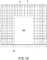
- the specific portion 34B of the third embodiment is provided in the shielding wall 23 when the main building 15 is newly constructed, similarly to the first embodiment. Further, the position where the specific portion 34B is provided is also the position that separates the outside of the shielding wall 23 from the radiation controlled area 16, similarly to the first embodiment. When the main building 15 is newly constructed, the specific portion 34B is closed with the blocking portion 35B that constitutes part of the shielding wall 23.
- the shielding wall 23 is formed of reinforced concrete having reinforcing steel rods 41 inside.
- the blocking portion 35B for closing the specific portion 34B is made of unreinforced concrete without the reinforcing steel rods 41 inside. That is, the blocking portion 35B is a portion formed to have weaker strength than other portions of the shielding wall 23. In this manner, while the radiation is being shielded by concrete, the portion formed of unreinforced concrete can be configured as the blocking portion 35B that is lower in strength than other portions of the shielding wall 23.
- This specific portion 34B has a dimension such that it is opened from the floor surface to a predetermined height position.
- the blocking portion 35B is a portion that forms part of the shielding wall 23 and is weaker in strength than other portions of the shielding wall 23.
- a main building 15A in which a circular accelerator 3 and rotating gantries 5 are installed in different floors is illustrated. Adjacent to this main building 15A, an additional building with the same number of floors is constructed.
- the circular accelerator 3 may be installed on the first floor 42 and the specific portion 34C may be provided on the second floor 43 or on a higher floor.
- the specific portion 34C is provided in the shielding wall 23A on the second floor 43. This specific portion 34C is closed with a lid-shaped blocking portion 35C.
- the specific portion 34C is provided at the position that separates the outside of the shielding wall 23A from the radiation controlled area 16 in plan view.
- the specific portion 34C is provided at the position where the shielding wall 23A intersects with the virtual line obtained by extending the main transportation line 20 in the transportation direction in plan view, i.e., provided at the position further ahead in the direction in which the main transportation line 20 extends in plan view. In plan view, the specific portion 34C is provided at the position on the farther side from the circular accelerator 3 in the shielding wall 23A.
- the configuration of the fourth embodiment is provided with a floor reference portion 45 configured to indicate the height position of the floor surface 44 of the second floor 43 where the specific portion 34C exists.
- the floor reference portion 45 is provided at the position corresponding to the lower position of the specific portion 34C.
- the floor reference portion 45 is a plate-shaped portion that protrudes laterally from the outdoor wall surface of the shielding wall 23A on the second floor 43. The top face of the floor reference portion 45 coincides with the height position of the floor surface 44 of the second floor 43.
- the workers can check the height position of the floor surface 44 of the main building 15A (i.e., height serving as the reference for installing the equipment) by the floor reference portion 45 from the outdoor side of the shielding wall 23A without entering the radiation controlled area 16.
- the height position of the floor surface 44 of the main building 15A can be determined. In other words, though highly accurate installation position of 1 mm or less is required, height deviation between the existing equipment and the additional equipment is prevented, and thereby, returning of the process at the time of connecting the beam transportation line 4 can be prevented.
- the floor reference portion 45 is provided on the second floor 43 of the main building 15A in the fourth embodiment. However, when the floor corresponding to the specific portion 34C is the first floor or the basement floor, the floor reference portion 45 may be provided on the wall surface on the outdoor side of the shielding wall on the first floor or the basement floor.
- the floor reference portion 45 is a plate-shaped portion that protrudes laterally from the wall surface, this floor reference portion 45 may be a recess formed by denting the wall surface. Further, the floor reference portion 45 may be a marker provided on the wall surface.
- the configuration applied in any one of the embodiments may be applied to other embodiments or the configurations in the respective embodiments may be applied in combination.
- the opening dimension of the additional opening portion of the first embodiment may be the dimension of the additional opening portion of another embodiment.
- the rotating gantry 5 is provided in the treatment room 19 as an additional irradiation room in the above-described embodiments, another aspect may be adopted.
- the treatment room may be a fixed room in which an irradiator for irradiating a patient with the particle beam is fixedly disposed without providing the rotating gantry 5.
- the irradiation room as a target of the extension work may not be the treatment room 19 but may be an experiment room or the beam checking room.
- the floor height of the additional building 31 is the same as the floor height of the main building 15 in the above-described embodiments, the additional building 31 and the main building 15 may be on the same floor or the floor heights of both may be slightly different.
- a two-story additional building 31 may be constructed adjacent to the one-story main building 15 and these buildings 15 and 31 may be connected to each other.
- the additional building 31 is constructed so as to be integrated with the main building 15 in the above-described embodiments, the additional building 31 may be constructed at a position away from the main building 15. In this case, a connection passage extending from the specific portion 34 to the additional building 31 may be formed, and the beam transportation line may be extended by this passage from the main building 15 to the additional building 31.
- the specific portion 34 penetrates the shielding wall 23 in the horizontal direction in the above-described embodiments, another aspect may be adopted.
- the specific portion 34 may penetrate the shielding wall 23 in a slanting direction. Further, the specific portion 34 may be bent inside the shielding wall 23.
- the specific portion 34 is provided on the shielding wall 23 in the above-described embodiments, the specific portion 34 may be provided on the ceiling (i.e., shielding wall) that partitions the radiation controlled area 16. That is, the specific portion 34 may vertically penetrate the ceiling.
- the specific portion 34 is provided on the shielding wall 23 on the ground floor in the above-described embodiments, the specific portion 34 may be provided on the shielding wall 23 on the basement floor.
- the facilities for performing heavy-ion-beam cancer treatment are illustrated in the above-described embodiments, the above-described embodiments can be applied to other facilities.
- the above-described embodiments may be applied to a facility that performs proton-beam cancer treatment.
- the above-described embodiments may be applied to a facility that performs treatment under BNCT (Boron Neutron Capture Therapy). That is, the irradiator configured to radiate the particle beam may not only irradiate a patient with the particle beam but may also irradiate a predetermined target with the particle beam so as to generate neutrons.
- BNCT Billeron Neutron Capture Therapy
- the specific portion 34 is provided on the shielding wall 23 of the main building 15 in the above-described embodiments.
- another specific portion 34 may be newly provided on the additional shielding wall 32 of the additional building 31. In this case, when one more additional building is constructed after that, the specific portion 34 of the existing additional building 31 may be opened.
- the additional building 31 does not exist and only its extension site 30 is secured in the above-described embodiments.
- another aspect may be adopted.
- the specific portion 34 may be closed with the blocking portion 35.
- the specific portion 34 may be opened by removing the blocking portion 35.
- the specific portion capable of forming the additional opening portion of the irradiation room is provided, and thus, the operating rate can be improved by shortening the period during which the treatment is interrupted at the time of the construction work.
Abstract
Description
- Embodiments of the present invention relate to a particle beam therapy system, a particle beam therapy system construction method, and a particle beam therapy apparatus.
- In a conventional particle beam therapy system, therapy is performed by irradiating a lesion portion (cancer) of a patient with a particle beam. In the case of updating the system of such a particle beam therapy system, the system is updated by establishing a new treatment room and alternately operating this new treatment room and the existing treatment room while the treatment is being continued.
- [Patent Document 1]
JP 2018-038628 A - In the particle beam therapy system, a thick shielding wall for blocking radioactive rays is provided around a radiation controlled area where the accelerator is disposed. In the case of updating the system except in an unprepared treatment room that is provided in the building in advance, part of this shielding wall must be demolished and a path for extending the accelerator must be constructed. Thus, there is a problem that it takes a long time to demolish the shielding wall and this causes extended interruption period of treatment and reduction in operating rate of the system.
- In view of the above-described circumstances, an object of embodiments of the present invention is to provide technology for constructing a particle beam therapy system that can improve its operating rate by shortening the interruption period of treatment during construction.
-
-
Fig. 1 is a plan view illustrating a particle beam therapy system at the time of newly constructing it in the first embodiment. -
Fig. 2 is a plan view illustrating the particle beam therapy system at the time of extension in the first embodiment. -
Fig. 3 is a plan view illustrating a specific portion and a blocking portion in the first embodiment. -
Fig. 4 is a side view illustrating the specific portion and the blocking portion in the first embodiment. -
Fig. 5 is a plan view illustrating an electromagnet device. -
Fig. 6 is a flowchart illustrating a particle beam therapy system construction method at the time of newly constructing it. -
Fig. 7 is a flowchart illustrating a particle beam therapy system construction method at the time of extension. -
Fig. 8 is a plan view illustrating the specific portion and the blocking portion in the second embodiment. -
Fig. 9 is a plan view illustrating the specific portion and the blocking portion in the third embodiment. -
Fig. 10 is a side view illustrating the specific portion and the blocking portion in the third embodiment. -
Fig. 11 is a perspective view illustrating the specific portion and a floor reference portion in the fourth embodiment. - In one embodiment of the present invention, a particle beam therapy system comprising:
- a circular accelerator configured to accelerate charged particles;
- a beam transportation line configured to lead the charged particles accelerated by the circular accelerator to an irradiation room;
- a shielding wall that is disposed around a radiation controlled area and shields radiation to be generated from the circular accelerator and the beam transportation line, the radiation controlled area being an area where the circular accelerator and the beam transportation line are disposed;
- a specific portion that is provided at a position that separates the radiation controlled area from outside of the shielding wall and can form an additional opening portion of the irradiation room; and
- a blocking portion configured to close the specific portion and shield radiation passing through the specific portion.
- Hereinbelow, embodiments will be described by referring to the accompanying drawings. First, a description will be given of a particle beam therapy apparatus according to the first embodiment by referring to
Fig. 1 to Fig. 7 . Thereference sign 1 inFig. 1 indicates the particle beam therapy apparatus. In this particlebeam therapy system 1, therapy is performed by irradiating a lesion tissue (cancer) of a patient as a subject with a particle beam such as carbon ions. - Radiation therapy technology using the particle
beam therapy system 1 is also called heavy-particle-beam cancer therapy technology. In this technology, cancer lesions (affected areas) can be irradiated with carbon ions with pinpoint accuracy and damage to normal cells can be minimized while cancer lesions are being damaged. A particle beam is defined as heavier than an electron among radiation and includes a proton beam and a heavy particle beam. Of these, the heavy particle beam is defined as heavier than a helium atom. - As compared with conventional cancer treatment using X-rays, gamma rays, or proton rays, cancer treatment using heavy ion beams has a higher ability to kill cancer lesions and has the characteristic that the radiation dose is weak on the surface of the patient' s body and reaches a peak at the cancer lesions . Thus, it can reduce the number of irradiation and side effects and can shorten the treatment period.
- As shown in
Fig. 1 , the particlebeam therapy system 1 includes: anion source 2 configured to produce carbon ions that are charged particles; a ring-shapedcircular accelerator 3 that accelerates carbon ions into a particle beam; abeam transportation line 4 for transporting the particle beam; and rotating gantries 5 on which a patient to be irradiated with a particle beam is placed. - First, the carbon ions generated by the
ion source 2 are made incident on thecircular accelerator 3. These carbon ions are accelerated to about 70% of the speed of light while orbiting thecircular accelerator 3 about 1 million times, and thereby become a particle beam. This particle beam is led to two rotating gantries 5 via thebeam transportation line 4. - The
circular accelerator 3 includes: a high-frequency accelerating cavity that accelerates carbon ions by controlling the frequency of the magnetic field and the accelerating electric field; an injector that injects carbon ions from theion source 2 into thecircular accelerator 3; and an emission device that emits a particle beam of carbon ions from thecircular accelerator 3 to thebeam transportation line 4. - The
circular accelerator 3 and thebeam transportation line 4 are provided with vacuum ducts (i.e., beam pipes) 6 to 9, inside of which are evacuated (Fig. 5 ). The particle beam travels inside these vacuum ducts 6 to 9. The vacuum ducts 6 to 9 of thebeam transportation line 4 and thecircular accelerator 3 are integrated to form a transportation route that leads the particle beam to the rotating gantries 5. That is, the vacuum ducts 6 to 9 constitute a closed continuous space that has a degree of vacuum sufficient for passing the particle beam. - The
circular accelerator 3 andbeam transportation line 4 are provided withelectromagnet devices 10 to 12 that control the particle beam (Fig. 2 andFig. 5 ). Therespective electromagnet devices 10 to 12 are disposed so as to surround the outer circumference of the vacuum ducts 6 to 9. Further, a plurality ofelectromagnet devices 10 to 12 are disposed along the direction in which the vacuum ducts 6 to 9 extend. - Various types of
electromagnet devices 10 to 12 are used. For example, these include: adeflection electromagnet device 10 to be used in thecircular accelerator 3; aquadrupole electromagnet device 11 to be used in thebeam transportation line 4 for controlling the convergence and divergence of the particle beam; and adeflection electromagnet device 12 to be used for changing the traveling direction of the particle beam. - Each of the rotating gantries 5 is a large device having a cylindrical shape. Each of the rotating gantries 5 is installed such that the central axis of its cylindrical shape is along the horizontal direction. Each of the rotating gantries 5 can rotate around this axis. A vacuum duct and an electromagnet device extended from the
beam transportation line 4 are attached to each of the rotating gantries 5. In each of the rotating gantries 5, the vacuum duct is first led along the central axis of the rotating gantry 5, once extends toward the cylindrical outer peripheral side of the rotating gantry 5, and then extends toward the inner peripheral side of the rotating gantry 5 again. - Each of the rotating gantries 5 are provided with an irradiator that irradiates the patient with the particle beam having been led by the
beam transportation line 4. This particle beam is scanned in two directions, which are orthogonal to the beam traveling direction, so as to be radiated from the irradiator. The patient is placed on the bed inside one rotating gantry 5. This bed can be moved in the state where the patient is placed on it. This movement of the bed enables positioning by which the patient is moved to the irradiation position of the particle beam. Thus, the particle beam can be radiated onto the lesion tissue of the patient with optimum accuracy. - Further, the irradiator can be rotated around the patient by rotating the rotating gantry 5. The particle beam can be emitted from any direction around the patient. That is, each of the rotating gantries 5 is a device that can change the irradiation direction of the charged particles having been led by the
beam transportation line 4 with respect to the patient. Thus, the particle beam can be accurately radiated onto the lesion portion from the optimum direction while burden on the patient is being reduced. - The particle beam loses its kinetic energy at the time of passing through the body of the patient so as to decrease its velocity and receive a resistance that is approximately inversely proportional to the square of the velocity, and stops rapidly when it decreases to a certain velocity. Near the stopping point of the particle beam, high energy called Bragg peak is emitted. The particle
beam therapy system 1 matches this Bragg peak with the position of the lesion tissue (affected part) of the patient, and thus, can kill only the lesion tissue while suppressing damage to normal tissues. - As shown in
Fig. 1 , the particlebeam therapy system 1 includes amain building 15 that houses thecircular accelerator 3, thebeam transportation line 4, and the rotating gantries 5. Themain building 15 is a robust building made of reinforced concrete. The first embodiment illustrates themain building 15 in which thecircular accelerator 3, thebeam transportation line 4, and the rotating gantries 5 are all installed in the same floor. - The inside of the
main building 15 is divided into a normal area and a radiation controlledarea 16 including the accelerator room in which thecircular accelerator 3 is installed. The radiation controlledarea 16 is an area provided to prevent unnecessary entry of people and their unnecessary exposure to radiation by being clearly classified as a place where the radiation dose is a certain amount or more. The establishment of this radiation controlledarea 16 is stipulated by law. - The
circular accelerator 3, thebeam transportation line 4, and the rotating gantries 5 are provided in the radiation controlledarea 16 because they are devices that emit radioactive rays during operation. There are two rotating gantries 5 in the radiation controlledarea 16 of themain building 15. Thefirst treatment room 17 and thesecond treatment room 18 are provided such that the respective rotating gantries 5 are disposed in the first andsecond treatment rooms treatment rooms - The
beam transportation line 4 is composed of: amain transportation line 20 extending from thecircular accelerator 3; andsub-transportation lines main transportation line 20 and extending to thetreatment rooms deflection electromagnet device 12 capable of changing the traveling direction of the particle beam is provided in the portion where thesub-transportation lines main transportation line 20. - The
main building 15 includes: a shieldingwall 23 that partitions the periphery of the radiation controlledarea 16 and shields radiation; and anormal wall 24 that is used in the normal area and is not supposed to shield radiation. - The shielding
wall 23 prevents radiation from leaking outside the radiation controlledarea 16. The thickness T of this shieldingwall 23 is 1 to 2 m or more. When a metal plate such as lead or iron is provided inside the shieldingwall 23, the thickness T of the shieldingwall 23 may be less than 1 m. The ceiling portion of the radiation controlledarea 16 is covered with a ceiling plate made of concrete and having a predetermined thickness. - Radiation is mainly generated in the beam deflecting portion and the stopping portion (i.e., disappearing portion), and is particularly generated in the tangential direction when the beam is deflected. Thus, in the case of disposing the
circular accelerator 3 or thebeam transportation line 4 horizontally, the structure should have sufficient shielding ability in the horizontal direction. Hence, the shieldingwall 23 has a greater shielding ability than the ceiling plate. - Inside the
main building 15, facilities such as alobby 25, acorridor 26, aconsultation room 27, astaff room 28, and apatient waiting room 29 are usually provided in the normal area. The human entrance path from thepatient waiting room 29 to thetreatment rooms wall 23 and is formed into a bent crank shape in plan view. Thus, radiation does not leak from thetreatment rooms patient waiting room 29. - In the present embodiment, a
controller 50 configured to control thecircular accelerator 3, thebeam transportation line 4, and the rotating gantries 5 is provided in themain building 15. Thecontroller 50 includes aninterlock 51 that constantly monitors whether a predetermined safety condition is satisfied or not. When the predetermined safety condition is not satisfied, theinterlock 51 prohibits the operation of thecircular accelerator 3. When thecircular accelerator 3 is in operation and the predetermined safety condition is not satisfied, theinterlock 51 causes thecircular accelerator 3 to make an emergency stop. - A large budget is required to construct the particle
beam therapy system 1. Thus, in the case of newly constructing the particlebeam therapy system 1, the number of facilities such astreatment rooms extension site 30 adjacent to themain building 15 is secured in advance. - As shown in
Fig. 2 , theadditional building 31 is provided with one rotating gantry 5. Thethird treatment room 19 corresponding to this rotating gantry 5 is provided. Thistreatment room 19 is an irradiation room where irradiation of charged particles is performed. Along with the addition of thisthird treatment room 19, other facilities such as thepatient waiting room 29 are also added. - The
additional building 31 is built so as to be integrated with themain building 15. In other words, theadditional building 31 is a building that has the rotating gantry 5 to be installed in the same floor as themain building 15. The height of the floor of theadditional building 31 is the same as that of themain building 15. - In this manner, at the time of newly constructing the particle
beam therapy system 1, this initial cost can be reduced by reducing the installation number of rotating gantries 5 which are the most expensive devices, and after that, its operating rate can be improved by adding the rotating gantry 5. - The inside of the
additional building 31 is divided into the radiation controlledarea 16 and the normal area. The radiation controlledarea 16 of theadditional building 31 is expanded from themain building 15. Further, theadditional building 31 includes: anadditional shielding wall 32 that partitions the periphery of the radiation controlledarea 16; and an additionalnormal wall 33 to be used in the normal area. - Since there is no
circular accelerator 3 in theadditional building 31, thebeam transportation line 4 is extended from themain building 15 to theadditional building 31. Thebeam transportation line 4 is extended through aspecific portion 34 that is an additional opening portion provided in the shieldingwall 23 of themain building 15. The extension is performed by connecting thebeam transportation line 4 in themain building 15 and the additionalbeam transportation line 4 to be provided in theadditional building 31. In the present embodiment, thespecific portion 34 is provided in advance when themain building 15 is newly constructed. - In the following description, it is assumed that the left side of the respective sheets of
Fig. 1 andFig. 2 is the west side of thebuildings buildings buildings buildings - As shown in
Fig. 1 , thespecific portion 34 is provided in the shieldingwall 23 when themain building 15 is newly constructed. Thisspecific portion 34 is an opening portion that penetrates the shieldingwall 23. In other words, thespecific portion 34 is a communication portion that communicates from themain building 15 to theadditional building 31. Further, a blockingportion 35 is provided, and this blockingportion 35 closes thespecific portion 34 and shields radiation passing through thespecific portion 34. In the first embodiment, the blockingportion 35 is a shielding door that shields radiation. - The "outside" of the present embodiment is exemplified by the outside where no roof is provided. The
specific portion 34 is provided at a position separating the outside of the shieldingwall 23 from the radiation controlledarea 16. For example, inmain building 15 inFig 1 , the west, north, and east walls of shieldingwall 23 face the outdoors. The south wall of the shieldingwall 23 faces indoors such as thepatient waiting room 29. For this reason, thespecific portion 34 is provided on the east side of the shieldingwall 23. - Note that the "outside" in the present embodiment does not necessarily have to be outdoors and may be indoors provided with a roof as long as it is outside the radiation controlled
area 16. For example, the position where thespecific portion 34 is provided may be a position that separates the radiation controlledarea 16 from the indoor space surrounded by thenormal wall 24 that can be readily removed. - Further, the
specific portion 34 is provided at a position that is on the side farther from thecircular accelerator 3 in the shieldingwall 23. For example, in themain building 15 inFig. 1 , thecircular accelerator 3 is provided so as to be biased to the west side in the radiation controlledarea 16. Thus, thespecific portion 34 is provided on the east side of the wall surfaces of the shieldingwall 23 facing the outdoors. When a boundary K is defined as a line that passes through the centroid Z of the radiation controlledarea 16 and is orthogonal to the line connecting the centroid Z and the center C of thecircular accelerator 3, the above-described disposition is the position of the region (i.e., east-side region) opposite to the west-side region where the center C of thecircular accelerator 3 is located with respect to this boundary K. That is, thespecific portion 34 is provided at the position opposite to the region where the center C of thecircular accelerator 3 is located with respect to the centroid Z of the radiation controlledarea 16 in plan view. - The "centroid" in the present embodiment is the position of the center of gravity of the figure, and is the point at which the figure balances in the case of using the position as the fulcrum. For example, when the figure is a rectangle, its centroid is the intersection of the diagonals of the rectangle.
- The
circular accelerator 3 and thetreatment rooms area 16. When thecircular accelerator 3 is installed in one side in the radiation controlledarea 16, thetreatment rooms treatment room 19 close to thetreatment rooms beam transportation line 4 can be extended in a short distance from themain building 15 to theadditional building 31 through thespecific portion 34. - The
specific portion 34 is provided further ahead in the direction in which themain transportation line 20 extends. In themain building 15 inFig. 1 , themain transportation line 20 extends from thecircular accelerator 3 on the west side to the east side, and the particle beam is transported from the west side to the east side. For this reason, thespecific portion 34 is provided at a position where the shieldingwall 23 intersects with the virtual line V obtained by extending themain transportation line 20 downstream in the transportation direction. In this manner, when thethird treatment room 19 is added, thebeam transportation line 4 can be extended to theadditional building 31 without providing an additionaldeflection electromagnet device 12 in themain building 15. - At the end of the
main transportation line 20, asub-transportation line 22 extending to thesecond treatment room 18 located farthest from thecircular accelerator 3 is provided. Adeflection electromagnet device 12b is provided at the connection portion between thissub-transportation line 22 and themain transportation line 20. Thespecific portion 34 may be provided near thisdeflection electromagnet device 12b. - the
specific portion 34 is disposed at a position that separates the radiation controlledarea 16 from theextension site 30 of thethird treatment room 19 in the shieldingwall 23. In themain building 15 inFig. 1 , theextension site 30 is provided on the east side of themain building 15. Accordingly, thespecific portion 34 is provided on the east side of the shieldingwall 23. In this manner, an additional opening portion can be provided near theextension site 30 of thethird treatment room 19, and thus, the extension path of thebeam transportation line 4 can be minimized. - As shown in
Fig. 3 andFig. 4 , thespecific portion 34 is an opening portion having a rectangular shape in side view. Thisspecific portion 34 is formed by horizontally penetrating the shieldingwall 23 when themain building 15 is newly constructed. The blockingportion 35 for closing thespecific portion 34 is a shielding door that is provided with ametal plate 36 such as lead or iron inside. Since thespecific portion 34 is closed with the blockingportion 35, radiation does not leak to the outside from the radiation controlledarea 16. - The opening dimension Q1 of the
specific portion 34 in the vertical direction is approximately 60 cm. The opening dimension Q1 of thespecific portion 34 in the lateral direction is approximately 80 cm. The vertical and lateral opening dimensions Q1 and Q2 of thespecific portion 34 are preferably 1 m or less. For example, the dimension L1 in the lateral direction and the dimension L2 in the longitudinal direction of thedeflection electromagnet device 12 to be used in thebeam transportation line 4 are about 1 to 2 m (Fig. 5 ) . The opening dimensions Q1 and Q2 of thespecific portion 34 are set in such a manner that thedeflection electromagnet device 12 cannot pass through thespecific portion 34. The dimension of other electromagnet devices is also about 1 to 2 m. - Since the vertical and lateral opening dimensions Q1 and Q2 of the
specific portion 34 are 1 m or less,cables 37 and avacuum duct 8 constituting an additionalbeam transportation line 4 can be installed via thespecific portion 34 with its opening dimension minimized. Since the opening dimension is minimized, the robustness of themain building 15 can be maintained and the thickness of the shieldingwall 23 can be minimized. - Under the state where the
specific portion 34 is opened,various cables 37 and thevacuum duct 8 of the additionalbeam transportation line 4 are installed across themain building 15 and theadditional building 31. Of the opening dimension Q2 of thespecific portion 34 in the lateral direction, the opening dimension Q3 on the right side is used to lead out thevacuum duct 8 and thevarious cables 37. This opening dimension Q3 is about 20 cm. This opening dimension Q3 is a dimension corresponding to the diameter of thevacuum duct 8. - The opening dimension Q4 on the left side is used by an operator who performs the extension work to move back and forth between the
main building 15 and theadditional building 31. This opening dimension Q4 is about 60 cm. Further, thespecific portion 34 is provided at a predetermined height position H from the floor surface. This height position H is about 1 m. This height position H is set depending on the height position of the existing vacuum duct 7. - In the
specific portion 34 of the present embodiment, it is preferred to secure another opening portion that is different from both of the entrance/exit to be used by people as a normal approach path and a carry-in entrance of equipment at the time of newly constructing the building. In other words, in the shieldingwall 23 of themain building 15, thespecific portion 34 is provided in addition to the normal entrance/exit of people and the carry-in entrance of equipment at the time of newly constructing the building. - The carry-in entrance of equipment such as
electromagnet devices 10 to 12 at the time of newly constructing the building is provided in the ceiling portion of the radiation controlledarea 16. This carry-in entrance is covered with a ceiling plate made of concrete after carrying in the equipment. - The carry-in entrance of equipment at the time of newly constructing the building may be provided on the shielding
wall 23. In this case, however, the opening dimension of the carry-in entrance will be about 5 m at maximum, so the structure of the building will be fragile as it is, and consequently, the thickness of the shieldingwall 23 needs to be thicker than required for the shielding performance. For this reason, after the equipment has been carried in, it will be reconstructed and the carry-in entrance will be blocked with the same structure as the surrounding area. At this time, thespecific portion 34 can be provided by adjusting the opening dimension without completely closing the opening. Incidentally, the carry-in entrance may be provided at an appropriate position for providing thespecific portion 34 and this carry-in entrance may be used as thespecific portion 34. - At the time of loading the equipment at the new construction there is no need for radiation control because it is before the start of operation. Thus, in the conventional carry-in entrance of equipment at the time of newly constructing the building, sufficient measures are not taken against radiation leakage. Contrastively, the shielding door that is the blocking
portion 35 in the first embodiment is a door that does not open during normal times after starting treatment. Thus, no handle is provided on this shielding door. Further, this shielding door is provided with anoperation unit 49 that can be opened only from the side of the radiation controlledarea 16 in the shieldingwall 23. Thisoperation unit 49 is a lock that can be unlocked only from the side of the radiation controlledarea 16. In other words, the shielding door is a mechanism that can be opened only from the inside (i.e., radiation controlled area 16). At the time of operating theoperation unit 49 in order to open the shielding door, a predetermined tool (for example, a detachable handle) is used to open it. A handle may be provided on the shielding door in the same manner as a normal door. - Until the extension work is completed, the interlock 51 (
Fig. 1 ) stops the operation of the device when the blocking state of the blockingportion 35 changes due to opening of the shielding door. This can prevent unintended leakage of radiation after the start of treatment. - As shown in
Fig. 3 andFig. 4 , an opening/closing sensor 52 configured to detect an open/closed state is provided in the blockingportion 35 that is a shielding door. On the basis of the information acquired by the opening/closing sensor 52, the interlock 51 (Fig. 1 ) of thecontroller 50 determines whether the shielding door is opened or not. When the shielding door is opened and thecircular accelerator 3 is in operation, processing of urgently stopping the operation of thecircular accelerator 3 is performed. - In the present embodiment, at the time of newly constructing the
main building 15, thespecific portion 34 is constructed in advance. Afterward, at the time of constructing theadditional building 31, an additional opening portion can be readily provided on the shieldingwall 23 by opening thespecific portion 34. Since destruction of the shieldingwall 23 is not necessary for forming the additional opening portion, the construction period can be significantly shortened. The work of removing the blockingportion 35 is usually completed within 1 day, in about 2 hours. - When the extension work (i.e., construction of the additional building 31) is performed, the shielding
wall 32 of theadditional building 31 is constructed in advance. Further, equipment such as theadditional vacuum duct 8, thequadrupole electromagnet device 11, thedeflection electromagnet device 12c, and the rotating gantry 5 is carried into theadditional building 31 and assembled. These works can be performed during the day while usual treatment is being continued in themain building 15. After the equipment of theadditional building 31 is installed, thespecific portion 34 is opened, and the vacuum duct 7 of thebeam transportation line 4 of themain building 15 is connected to thevacuum duct 8 of thebeam transportation line 4 of theadditional building 31. In other words, the connection work between the existing vacuum duct 7 and theadditional vacuum duct 8 is performed at the end of the equipment assembly process. - The work of opening the
specific portion 34 and connecting thevacuum ducts 7 and 8 can be done in about one day. In other words, when this work is performed in a period during which normal treatment is not performed in the main building 15 (for example, at night or on holidays such as weekends), the extension work can be completed without reducing the operating rate of the particlebeam therapy system 1. - As in the conventional technology, in the case of providing an opening for the shielding
wall 23 that separates the radiation controlledarea 16 from the outside, the equipment such as thecircular accelerator 3 must be stopped in order to prevent radiation from leaking to the outside. This is because the construction will not be completed in one day and appropriate radiation shielding will be required during or after the opening is provided. Even if the problem of radiation is solved, vibration (noise) generated at the time of making a hole in the wall adversely affects the treatment, and thus, the construction must be interrupted during the treatment. In the conventional technology, there is a period during which normal medical treatment cannot be performed, because the equipment has to be stopped at the time of constructing the additional opening portion in the shieldingwall 23. - However, in the present embodiment, the
specific portion 34 is provided in advance of newly constructing themain building 15, and thus, the period during which normal treatment cannot be performed can be eliminated at the time of the extension work. Further, there is no need to perform large-scale construction in themain building 15 at the time of the extension work. - In particular, in particle beam therapy, it is generally necessary to continue treatment for 3 to 4 days per week for several weeks. Thus, if there is a period during which treatment cannot be performed for 4 days or more, the treatment will have to be restarted from the beginning. In the present embodiment, it is not necessary to interrupt the treatment even in the case of adding equipment. Thus, the operation rate of the particle
beam therapy system 1 can be improved. - When the
additional building 31 is constructed, it is necessary to perform positioning on both of the existing equipment and the additional equipment before both are actually connected. When the blockingportion 35 is opened in such a case, the positioning of the additional equipment can be performed in accordance with the existing equipment, and after the positioning is completed, the opening can be closed immediately to block radiation. In the positioning, in addition to the equipment installation work, the reference point may be transferred. This work can also be performed in a period during which normal treatment is not performed such as nighttime or holidays including weekends. Since the blockingportion 35 can be opened and closed as necessary, the treatment using the particlebeam therapy system 1 can be continued even in the period of the extension work. - As shown in
Fig. 5 , thebeam transportation line 4 includes:normal vacuum ducts 7 and 8 having no branch; and a branchingvacuum duct 9 to be branched in two directions. The branchingvacuum duct 9 is provided at the branch portion of themain transportation line 20 and thesub-transportation lines 21 and 22 (Fig. 1 ). Aflange 38 for connection is provided at the ends of thenormal vacuum ducts 7 and 8, and anotherflange 39 for connection is also provided at the end of the branchingvacuum duct 9. - At these branch portions,
deflection electromagnet devices Fig. 1 ). The magnetic field to be generated by thesedeflection electromagnet devices main transportation line 20 to move straight or bend toward thesub-transportation lines - At the time of newly constructing the
main building 15, thesub-transportation line 22 extending to thesecond treatment room 18 is connected to the end of themain transportation line 20, but it does not need to be branched. However, thesub-transportation line 22 is connected to themain transportation line 20 by using the branchingvacuum duct 9 in advance. - A closing
flange 40 is attached to theflange 39 at one end of the branchingvacuum duct 9. The closingflange 40 closes one end of the branchingvacuum duct 9. One end of the branchingvacuum duct 9 serves as a connecting portion to which theadditional vacuum duct 8 can be connected. Further, this branchingvacuum duct 9 is provided in the portion closest to thespecific portion 34 in thebeam transportation line 4 of themain building 15. - A closing valve may be provided on the
flange 39 at one end of the branchingvacuum duct 9. In this manner, when theadditional vacuum duct 8 is connected to one end of the branchingvacuum duct 9 via a closing valve and opening and closing of this closing valve is appropriately performed, thebeam transportation line 4 can be tested or adjusted. - At the time of constructing the
additional building 31, the closingflange 40 is removed from the branchingvacuum duct 9, and thereby, theadditional vacuum duct 8 can be connected. In this manner, at the time of constructing theadditional building 31, theadditional vacuum duct 8 can be connected without replacing the parts of thebeam transportation line 4 of themain building 15, and thus, the work can be completed in a short period. - Although the branching
vacuum duct 9 is provided at the end of themain transportation line 20 at the time of newly constructing themain building 15 in the present embodiment, another aspect may be adopted. - For example, at the time of newly constructing the
main building 15, thesub-transportation line 22 is connected to the end of themain transportation line 20 via a vacuum duct bent in one direction. In this aspect, during the regular inspection period of the particlebeam therapy system 1, the vacuum duct bent in one direction at the end of themain transportation line 20 may be replaced by the branchingvacuum duct 9. - In the present embodiment, the
controller 50 configured to control thecircular accelerator 3, thebeam transportation line 4, and the rotating gantries 5 is provided in themain building 15. When anotherbeam transportation line 4 and another rotating gantry 5 are added, the controller for controlling these added devices may be added to theadditional building 31 or the existingcontroller 50 in themain building 15 may be used for controlling these added devices. - Next, a particle beam therapy system construction method at time of newly constructing it will be described by referring to the flowchart of
Fig. 6 . - First, in the next step S11, work of newly constructing the
main building 15 is started. - In the next step S12, the shielding
wall 23 of themain building 15 is constructed. - In the next step S13, the
specific portion 34 is provided on the shieldingwall 23 of themain building 15. - In the next step S14, the
specific portion 34 is closed with the blockingportion 35. - In the next step S15, the
treatment rooms main building 15 are constructed. - In the next step S16, the
circular accelerator 3 is carried into the radiation controlledarea 16 of themain building 15. - In the next step S17, the
beam transportation line 4 is carried into the radiation controlledarea 16 of themain building 15. - In the next step S18, the rotating gantries 5 are carried into the
respective treatment rooms main building 15. - In the next step S19, test or adjustment is performed on various facilities having been carried into the
main building 15, such as thecircular accelerator 3, thebeam transportation line 4, and the rotating gantries. - In the next step S20, the work of newly constructing the
main building 15 is completed. - In the next step S21, treatment is started at the new facilities in the
main building 15. - Next, a particle beam therapy system construction method at time of extension work (i.e., additionally constructing a building) will be described by referring to the flowchart of
Fig. 7 . - First, in the next step S31, extension work is started at the
extension site 30 adjacent to themain building 15. The treatment using the equipment of themain building 15 is continued. - In the next step S32, the
additional shielding wall 32 of theadditional building 31 is constructed. - In the next step S33, the
third treatment room 19 of theadditional building 31 is constructed. - In the next step S34, another
beam transportation line 4 is carried into theadditional building 31. - In the next step S35, another rotating gantry 5 is carried into the
third treatment room 19 of theadditional building 31. - In the next step S36, the blocking
portion 35 closing thespecific portion 34 of themain building 15 is operated such that thespecific portion 34 is opened. Thebeam transportation line 4 of themain building 15 and thebeam transportation line 4 ofadditional building 31 are connected. These works can be performed on holidays or at night. At this time, theadditional shielding wall 32 is already constructed, and thus, it is easy to set the radiation controlledarea 16 and there is no need to worry about shielding after opening thespecific portion 34. - In the next step S37, the extension work of the
additional building 31 is completed. - In the next step S38, on other holidays or during another night period, test or adjustment is performed on various facilities having been carried into
additional building 31, such as thecircular accelerator 3, thebeam transportation line 4, and the rotating gantry 5. - In the next step S39, treatment is started using the added facilities in the
additional building 31. - Next, the
specific portion 34A and the blockingportion 35A of the second embodiment will be described by referring toFig. 8 . The same components as those shown in the above-described embodiment are denoted by the same reference signs, and duplicate description is omitted. - As shown in
Fig. 8 , thespecific portion 34A of the second embodiment is formed by horizontally penetrating the shieldingwall 23 when themain building 15 is newly constructed. Thisspecific portion 34A is provided on the shieldingwall 23 at the time of newly constructing themain building 15, similarly to the first embodiment. Further, the position where thespecific portion 34A is provided is also the position that separates the outside of the shieldingwall 23 from the radiation controlledarea 16, similarly to the first embodiment. - The blocking
portion 35A for closing thespecific portion 34A is a shielding block in which ametal plate 36 such as lead or iron is provided. The blockingportion 35A is a member having a convex shape in cross-section. The member may not be integrated but may be divided into a plurality of parts for easy handling. This blockingportion 35A can be attached to thespecific portion 34A from the outside. Further, the blockingportion 35A can be removed from thespecific portion 34A. - The blocking
portion 35A may be locked such that it cannot be readily opened. Further, the blockingportion 35A may be provided with theoperation unit 49 that can be released only from the side of the radiation controlledarea 16. That is, the blockingportion 35A may be a mechanism that can be opened only from the inside (i.e., from the radiation controlled area 16). Further, theinterlock 51 may be provided to stop the operation of the device when the closing state of the blockingportion 35A changes. - When the
additional building 31 is constructed, under the state where thespecific portion 34A is opened,various cables 37 and theadditional vacuum duct 8 of thebeam transportation line 4 are led from themain building 15 to theadditional building 31. Radiation does not leak from the radiation controlledarea 16 to the outside by closing thespecific portion 34A with this blockingportion 35A. - When the
main building 15 is newly constructed, the blockingportion 35A configured as a heavy and strong shielding block is attached to thespecific portion 34A. In this case, when theadditional building 31 is constructed, this heavy andstrong blocking portion 35A may be replaced by another blockingportion 35A that is a lightweight and simple shielding block. Since it is replaced by a lightweight shielding block, it becomes easier to attach and detach the blockingportion 35A at the time of constructing theadditional building 31. - In the second embodiment, the blocking
portion 35A is a shielding block that can be attached to and detached from thespecific portion 34A. Thus, when an additional treatment room is constructed, the work of opening the additional opening portion can be readily performed without breaking the shieldingwall 23. - Next, the
specific portion 34B and the blockingportion 35B of the third embodiment will be described by referring toFig. 9 andFig. 10 . The same components as those shown in the above-described embodiments are denoted by the same reference signs, and duplicate description is omitted. - As shown in
Fig. 9 , thespecific portion 34B of the third embodiment is provided in the shieldingwall 23 when themain building 15 is newly constructed, similarly to the first embodiment. Further, the position where thespecific portion 34B is provided is also the position that separates the outside of the shieldingwall 23 from the radiation controlledarea 16, similarly to the first embodiment. When themain building 15 is newly constructed, thespecific portion 34B is closed with the blockingportion 35B that constitutes part of the shieldingwall 23. - As shown in
Fig. 10 , most of the shieldingwall 23 is formed of reinforced concrete having reinforcingsteel rods 41 inside. The blockingportion 35B for closing thespecific portion 34B is made of unreinforced concrete without the reinforcingsteel rods 41 inside. That is, the blockingportion 35B is a portion formed to have weaker strength than other portions of the shieldingwall 23. In this manner, while the radiation is being shielded by concrete, the portion formed of unreinforced concrete can be configured as the blockingportion 35B that is lower in strength than other portions of the shieldingwall 23. - When the
additional building 31 is constructed, work of penetrating the blockingportion 35B made of unreinforced concrete is performed, and thereby, an additional opening portion is formed in thespecific portion 34B. Thisspecific portion 34B has a dimension such that it is opened from the floor surface to a predetermined height position. - In the third embodiment, the blocking
portion 35B is a portion that forms part of the shieldingwall 23 and is weaker in strength than other portions of the shieldingwall 23. Thus, while a large opening portion is being secured, the work of forming the additional opening portion can be performed in a short period when an additional treatment room is constructed. - Next, the
specific portion 34C and the blockingportion 35C of the fourth embodiment will be described by referring toFig. 11 . The same components as those shown in the above-described embodiments are denoted by the same reference signs, and duplicate description is omitted. - As shown in
Fig. 11 , in the fourth embodiment, amain building 15A in which acircular accelerator 3 and rotating gantries 5 are installed in different floors is illustrated. Adjacent to thismain building 15A, an additional building with the same number of floors is constructed. In the case of themain building 15A with two or more floors, thecircular accelerator 3 may be installed on thefirst floor 42 and thespecific portion 34C may be provided on thesecond floor 43 or on a higher floor. In thismain building 15A, thespecific portion 34C is provided in the shieldingwall 23A on thesecond floor 43. Thisspecific portion 34C is closed with a lid-shapedblocking portion 35C. - Even when the floor where the
circular accelerator 3 is provided is different from the floor where thespecific portion 34C is provided, thespecific portion 34C is provided at the position that separates the outside of the shieldingwall 23A from the radiation controlledarea 16 in plan view. Thespecific portion 34C is provided at the position where the shieldingwall 23A intersects with the virtual line obtained by extending themain transportation line 20 in the transportation direction in plan view, i.e., provided at the position further ahead in the direction in which themain transportation line 20 extends in plan view. In plan view, thespecific portion 34C is provided at the position on the farther side from thecircular accelerator 3 in the shieldingwall 23A. - The configuration of the fourth embodiment is provided with a
floor reference portion 45 configured to indicate the height position of thefloor surface 44 of thesecond floor 43 where thespecific portion 34C exists. Thefloor reference portion 45 is provided at the position corresponding to the lower position of thespecific portion 34C. Thefloor reference portion 45 is a plate-shaped portion that protrudes laterally from the outdoor wall surface of the shieldingwall 23A on thesecond floor 43. The top face of thefloor reference portion 45 coincides with the height position of thefloor surface 44 of thesecond floor 43. - In this manner, at the time of constructing the additional building, the workers can check the height position of the
floor surface 44 of themain building 15A (i.e., height serving as the reference for installing the equipment) by thefloor reference portion 45 from the outdoor side of the shieldingwall 23A without entering the radiation controlledarea 16. On the basis of the checked height position of thefloor surface 44 of themain building 15A, the height position of the floor surface of the second floor of the additional building can be determined. In other words, though highly accurate installation position of 1 mm or less is required, height deviation between the existing equipment and the additional equipment is prevented, and thereby, returning of the process at the time of connecting thebeam transportation line 4 can be prevented. - The
floor reference portion 45 is provided on thesecond floor 43 of themain building 15A in the fourth embodiment. However, when the floor corresponding to thespecific portion 34C is the first floor or the basement floor, thefloor reference portion 45 may be provided on the wall surface on the outdoor side of the shielding wall on the first floor or the basement floor. - Although the
floor reference portion 45 is a plate-shaped portion that protrudes laterally from the wall surface, thisfloor reference portion 45 may be a recess formed by denting the wall surface. Further, thefloor reference portion 45 may be a marker provided on the wall surface. - Although the particle beam therapy system has been described on the basis of the first to fourth embodiments, the configuration applied in any one of the embodiments may be applied to other embodiments or the configurations in the respective embodiments may be applied in combination. For example, the opening dimension of the additional opening portion of the first embodiment may be the dimension of the additional opening portion of another embodiment.
- Although a mode in which each step is executed in series is illustrated in the flowcharts of in the above-described embodiments, the execution order of the respective steps is not necessarily fixed and the execution order of part of the steps may be changed. Additionally, some steps may be executed in parallel with another step.
- Although the rotating gantry 5 is provided in the
treatment room 19 as an additional irradiation room in the above-described embodiments, another aspect may be adopted. For example, the treatment room may be a fixed room in which an irradiator for irradiating a patient with the particle beam is fixedly disposed without providing the rotating gantry 5. Further, the irradiation room as a target of the extension work may not be thetreatment room 19 but may be an experiment room or the beam checking room. - Although the floor height of the
additional building 31 is the same as the floor height of themain building 15 in the above-described embodiments, theadditional building 31 and themain building 15 may be on the same floor or the floor heights of both may be slightly different. A two-storyadditional building 31 may be constructed adjacent to the one-storymain building 15 and thesebuildings - Although the
additional building 31 is constructed so as to be integrated with themain building 15 in the above-described embodiments, theadditional building 31 may be constructed at a position away from themain building 15. In this case, a connection passage extending from thespecific portion 34 to theadditional building 31 may be formed, and the beam transportation line may be extended by this passage from themain building 15 to theadditional building 31. - Although the
specific portion 34 penetrates the shieldingwall 23 in the horizontal direction in the above-described embodiments, another aspect may be adopted. For example, when thebeam transportation line 4 is disposed diagonally with respect to the horizontal plane, thespecific portion 34 may penetrate the shieldingwall 23 in a slanting direction. Further, thespecific portion 34 may be bent inside the shieldingwall 23. - Although the
specific portion 34 is provided on the shieldingwall 23 in the above-described embodiments, thespecific portion 34 may be provided on the ceiling (i.e., shielding wall) that partitions the radiation controlledarea 16. That is, thespecific portion 34 may vertically penetrate the ceiling. - Although the
specific portion 34 is provided on the shieldingwall 23 on the ground floor in the above-described embodiments, thespecific portion 34 may be provided on the shieldingwall 23 on the basement floor. - Although the facilities for performing heavy-ion-beam cancer treatment are illustrated in the above-described embodiments, the above-described embodiments can be applied to other facilities. For example, the above-described embodiments may be applied to a facility that performs proton-beam cancer treatment. Further, the above-described embodiments may be applied to a facility that performs treatment under BNCT (Boron Neutron Capture Therapy). That is, the irradiator configured to radiate the particle beam may not only irradiate a patient with the particle beam but may also irradiate a predetermined target with the particle beam so as to generate neutrons.
- When the
main building 15 is newly constructed, thespecific portion 34 is provided on the shieldingwall 23 of themain building 15 in the above-described embodiments. However, when theadditional building 31 is constructed, anotherspecific portion 34 may be newly provided on theadditional shielding wall 32 of theadditional building 31. In this case, when one more additional building is constructed after that, thespecific portion 34 of the existingadditional building 31 may be opened. - When the
main building 15 is newly constructed, theadditional building 31 does not exist and only itsextension site 30 is secured in the above-described embodiments. However, another aspect may be adopted. For example, when themain building 15 is newly constructed, only the shieldingwall 32 of theadditional building 31 may be built together and thespecific portion 34 may be closed with the blockingportion 35. In this case, after the extension work is performed several years after the start of operation such that the equipment such as the rotating gantry 5 is added to theadditional building 31, thespecific portion 34 may be opened by removing the blockingportion 35. - According to at least one embodiment described above, the specific portion capable of forming the additional opening portion of the irradiation room is provided, and thus, the operating rate can be improved by shortening the period during which the treatment is interrupted at the time of the construction work.
- While certain embodiments have been described, these embodiments have been presented by way of example only, and are not intended to limit the scope of the inventions. Indeed, the novel methods and systems described herein may be embodied in a variety of other forms; furthermore, various omissions, substitutions and changes in the form of the methods and systems described herein may be made without departing from the subject-matter of the inventions. The above-cited invention and their equivalents are intended to cover such forms or modifications as would fall within the scope and the subject-matter of the inventions.
Claims (16)
- A particle beam therapy system comprising:a circular accelerator configured to accelerate charged particles;a beam transportation line configured to lead the charged particles accelerated by the circular accelerator to an irradiation room;a shielding wall that is disposed around a radiation controlled area and shields radiation to be generated from the circular accelerator and the beam transportation line, the radiation controlled area being an area where the circular accelerator and the beam transportation line are disposed;a specific portion that is provided at a position that separates the radiation controlled area from outside of the shielding wall and can form an additional opening portion of the irradiation room; anda blocking portion configured to close the specific portion and shield radiation passing through the specific portion.
- The particle beam therapy system according to claim 1, wherein the specific portion is disposed at a position opposite to a region where a center of the circular accelerator is located with respect to a centroid of the radiation controlled area in plan view.
- The particle beam therapy system according to claim 1 or claim 2, wherein:the beam transportation line is composed of a main transportation line extending from the circular accelerator and a sub-transportation line extending from the main transportation line to the irradiation room; andthe specific portion is disposed at a position including an intersection of the shielding wall and a virtual line obtained by extending the main transportation line downstream in a transportation direction.
- The particle beam therapy system according to any one of claim 1 to claim 3, wherein, in the shielding wall, the specific portion is disposed at a position that separates the radiation controlled area from an extension site of the irradiation room.
- The particle beam therapy system according to any one of claim 1 to claim 4, wherein opening dimension of the additional opening portion is 1 m or less.
- The particle beam therapy system according to any one of claim 1 to claim 5, further comprising:a branching vacuum duct that is disposed at a portion closest to the specific portion in the beam transportation line and branches in two directions; anda connection portion that is provided at one end of the branching vacuum duct and is connectable to an additional vacuum duct.
- The particle beam therapy system according to any one of claim 1 to claim 6, wherein:the specific portion is an opening portion penetrating the shielding wall; andthe blocking portion is a shielding door that shields the radiation.
- The particle beam therapy system according to any one of claim 1 to claim 6, wherein:the specific portion is an opening portion penetrating the shielding wall; andthe blocking portion is a shielding block that shields the radiation and is attachable to and detachable from the specific portion.
- The particle beam therapy system according to any one of claim 1 to claim 6, wherein the blocking portion is a portion that forms part of the shielding wall and is lower in strength than other portions of the shielding wall.
- The particle beam therapy system according to any one of claim 1 to claim 8, further comprising an operation unit that can open the blocking portion only from a side of the radiation controlled area.
- The particle beam therapy system according to any one of claim 1 to claim 10, further comprising an interlock configured to stop an operation of the circular accelerator when a closed state of the blocking portion changes.
- The particle beam therapy system according to any one of claim 1 to claim 11, further comprising a rotating gantry that is to be provided in the irradiation room and can change an irradiation direction of the charged particles having been led by the beam transportation line with respect to a subject.
- The particle beam therapy system according to any one of claim 1 to claim 12, further comprising a floor reference portion to be provided on an outer surface of the shielding wall and configured to indicate height position of a floor surface of a floor to which the specific portion corresponds.
- A particle beam therapy system construction method comprising steps of:providing a circular accelerator configured to accelerate charged particles at a time of newly constructing a particle beam therapy system;constructing a beam transportation line configured to lead the charged particles accelerated by the circular accelerator to an irradiation room, at the time of newly constructing a particle beam therapy system;constructing a shielding wall around a radiation controlled area at the time of newly constructing a particle beam therapy system, the shielding wall being configured to shield radiation to be generated from the circular accelerator and the beam transportation line, the radiation controlled area being an area in which the circular accelerator and the beam transportation line are disposed;providing a specific portion at the time of newly constructing a particle beam therapy system at a position that separates the radiation controlled area from outside of the shielding wall, the specific portion being able to form an additional opening portion of the irradiation room; andproviding a blocking portion at the time of newly constructing a particle beam therapy system, the blocking portion being configured to close the specific portion and block radiation having passed through the specific portion.
- The particle beam therapy system construction method according to claim 14, further comprising steps of:constructing an additional shielding wall around the specific portion at a time of additionally constructing the particle beam therapy system;constructing an additional beam transportation line at the time of additionally constructing the particle beam therapy system, the additional beam transportation line being configured to lead the charged particles to an irradiation room to be additionally constructed;opening the specific portion by removing the blocking portion at the time of additionally constructing the particle beam therapy system; andconnecting the beam transportation line to the additional beam transportation line via the specific portion at the time of additionally constructing the particle beam therapy system.
- A particle beam therapy apparatus comprising:a beam transportation line configured to lead charged particles to an irradiation room;a rotating gantry that is disposed in the irradiation room and can change an irradiation direction of the charged particles having been led by the beam transportation line with respect to a subject; anda connection portion that connects the beam transportation line to another beam transportation line in a building through a specific portion provided in advance at a time of constructing the building, the building being different in construction time from the beam transportation line.
Applications Claiming Priority (2)
| Application Number | Priority Date | Filing Date | Title |
|---|---|---|---|
| JP2018082245A JP7118720B2 (en) | 2018-04-23 | 2018-04-23 | Particle therapy system |
| PCT/JP2019/006985 WO2019207937A1 (en) | 2018-04-23 | 2019-02-25 | Particle beam therapy system, particle beam therapy system construction method, and particle beam therapy apparatus |
Publications (2)
| Publication Number | Publication Date |
|---|---|
| EP3785766A1 true EP3785766A1 (en) | 2021-03-03 |
| EP3785766A4 EP3785766A4 (en) | 2022-01-26 |
Family
ID=68294471
Family Applications (1)
| Application Number | Title | Priority Date | Filing Date |
|---|---|---|---|
| EP19792446.7A Pending EP3785766A4 (en) | 2018-04-23 | 2019-02-25 | Particle beam therapy system, particle beam therapy system construction method, and particle beam therapy apparatus |
Country Status (8)
| Country | Link |
|---|---|
| US (1) | US11583703B2 (en) |
| EP (1) | EP3785766A4 (en) |
| JP (1) | JP7118720B2 (en) |
| KR (1) | KR102528874B1 (en) |
| CN (1) | CN111971089A (en) |
| RU (1) | RU2755382C1 (en) |
| TW (1) | TWI720419B (en) |
| WO (1) | WO2019207937A1 (en) |
Families Citing this family (1)
| Publication number | Priority date | Publication date | Assignee | Title |
|---|---|---|---|---|
| JP7118720B2 (en) * | 2018-04-23 | 2022-08-16 | 株式会社東芝 | Particle therapy system |
Family Cites Families (31)
| Publication number | Priority date | Publication date | Assignee | Title |
|---|---|---|---|---|
| US5851182A (en) * | 1996-09-11 | 1998-12-22 | Sahadevan; Velayudhan | Megavoltage radiation therapy machine combined to diagnostic imaging devices for cost efficient conventional and 3D conformal radiation therapy with on-line Isodose port and diagnostic radiology |
| JPH10326699A (en) * | 1997-03-28 | 1998-12-08 | Mitsubishi Electric Corp | Charged particle irradiation device |
| DE10261099B4 (en) * | 2002-12-20 | 2005-12-08 | Siemens Ag | Ion beam system |
| JP3859605B2 (en) * | 2003-03-07 | 2006-12-20 | 株式会社日立製作所 | Particle beam therapy system and particle beam extraction method |
| KR100622935B1 (en) * | 2005-05-04 | 2006-09-13 | 삼성물산 주식회사 | Horizontal extension joint structuer and joint method using thereof |
| JP4537924B2 (en) * | 2005-09-29 | 2010-09-08 | 株式会社日立製作所 | Accelerator system |
| JP4451411B2 (en) * | 2006-03-31 | 2010-04-14 | 株式会社日立製作所 | Particle beam therapy system and beam course switching method thereof |
| JP5047083B2 (en) * | 2008-07-11 | 2012-10-10 | 株式会社日立製作所 | Particle beam therapy system |
| RU93026U1 (en) * | 2008-07-14 | 2010-04-20 | Институт ядерной физики им. Г.И. Будкера СО РАН | ACCELERATING COMPLEX FOR CANCER THERAPY BY PROTON AND ION BEAMS |
| WO2011048088A1 (en) * | 2009-10-23 | 2011-04-28 | Ion Beam Applications | Gantry comprising beam analyser for use in particle therapy |
| JP4871387B2 (en) * | 2009-10-29 | 2012-02-08 | 住友重機械工業株式会社 | Accelerated particle irradiation equipment and storage room structure |
| JP2011182987A (en) * | 2010-03-09 | 2011-09-22 | Sumitomo Heavy Ind Ltd | Accelerated particle irradiation equipment |
| JP5409521B2 (en) * | 2010-06-01 | 2014-02-05 | 株式会社日立製作所 | Particle beam therapy system |
| JP5535879B2 (en) | 2010-11-11 | 2014-07-02 | 住友重機械工業株式会社 | A charged particle beam irradiation apparatus, a charged particle beam irradiation method, and a method for attaching and detaching a transport line. |
| JP5710374B2 (en) * | 2011-05-11 | 2015-04-30 | 住友重機械工業株式会社 | Charged particle beam irradiation equipment |
| US8841638B2 (en) * | 2011-07-21 | 2014-09-23 | Mitsubishi Electric Corporation | Particle beam therapy system |
| US20130048883A1 (en) * | 2011-08-31 | 2013-02-28 | Sun Nuclear Corporation | Systems and methods for preventing unsafe medical treatment |
| JP6091263B2 (en) * | 2013-03-07 | 2017-03-08 | 三菱電機株式会社 | Particle therapy equipment |
| ES2575140T3 (en) * | 2013-07-10 | 2016-06-24 | Adam S.A. | Self-shielded vertical proton linear accelerator for proton therapy |
| JP6150650B2 (en) * | 2013-07-26 | 2017-06-21 | 株式会社日立製作所 | Particle beam irradiation system and its operation method |
| RU2526244C1 (en) * | 2013-08-28 | 2014-08-20 | Федеральное государственное бюджетное учреждение "Медицинский радиологический научный центр" Министерства здравоохранения РФ (ФГБУ МРНЦ Минздрава России) | Apparatus for remote neutron therapy |
| WO2016051550A1 (en) * | 2014-10-01 | 2016-04-07 | 株式会社日立製作所 | Particle beam therapy apparatus, and operation method therefor |
| JP6640480B2 (en) * | 2015-07-29 | 2020-02-05 | 株式会社東芝 | Particle beam transport system and segment thereof |
| JP6654102B2 (en) * | 2016-05-31 | 2020-02-26 | 株式会社日立製作所 | Particle beam therapy system |
| JP6719344B2 (en) * | 2016-09-08 | 2020-07-08 | 株式会社日立製作所 | Particle beam therapy system and system introduction method |
| JP6529524B2 (en) * | 2017-01-05 | 2019-06-12 | 住友重機械工業株式会社 | Particle therapy equipment |
| CN106924891B (en) * | 2017-04-28 | 2023-04-28 | 四川瑞迪医疗科技有限公司 | Radiotherapy preparation system |
| CN107596579B (en) * | 2017-10-12 | 2018-06-05 | 合肥中科离子医学技术装备有限公司 | Proton therapy system based on compact superconducting cyclotron |
| JP7061896B2 (en) * | 2018-03-02 | 2022-05-02 | 株式会社日立製作所 | How to renew the equipment of the particle beam therapy system and the particle beam therapy system |
| JP7118720B2 (en) * | 2018-04-23 | 2022-08-16 | 株式会社東芝 | Particle therapy system |
| JP2020048607A (en) * | 2018-09-21 | 2020-04-02 | 株式会社日立製作所 | Particle beam therapy system and extension method therefor |
-
2018
- 2018-04-23 JP JP2018082245A patent/JP7118720B2/en active Active
-
2019
- 2019-02-01 TW TW108104024A patent/TWI720419B/en active
- 2019-02-25 CN CN201980025499.2A patent/CN111971089A/en active Pending
- 2019-02-25 RU RU2020134697A patent/RU2755382C1/en active
- 2019-02-25 KR KR1020207025587A patent/KR102528874B1/en active IP Right Grant
- 2019-02-25 EP EP19792446.7A patent/EP3785766A4/en active Pending
- 2019-02-25 WO PCT/JP2019/006985 patent/WO2019207937A1/en unknown
-
2020
- 2020-09-30 US US17/037,839 patent/US11583703B2/en active Active
Also Published As
| Publication number | Publication date |
|---|---|
| JP2019187687A (en) | 2019-10-31 |
| JP7118720B2 (en) | 2022-08-16 |
| US11583703B2 (en) | 2023-02-21 |
| US20210008393A1 (en) | 2021-01-14 |
| WO2019207937A1 (en) | 2019-10-31 |
| KR102528874B1 (en) | 2023-05-08 |
| RU2755382C1 (en) | 2021-09-15 |
| TWI720419B (en) | 2021-03-01 |
| TW201945046A (en) | 2019-12-01 |
| KR20200118139A (en) | 2020-10-14 |
| CN111971089A (en) | 2020-11-20 |
| EP3785766A4 (en) | 2022-01-26 |
Similar Documents
| Publication | Publication Date | Title |
|---|---|---|
| JP4632278B2 (en) | Ion beam therapy system and method of operating the system | |
| US6894300B2 (en) | Ion beam facility | |
| JP2009217938A (en) | Accelerator system and particle beam medical treatment system | |
| JP5791786B2 (en) | Rotating gantry and particle beam therapy system | |
| US20090309047A1 (en) | Particle therapy system | |
| US11247073B2 (en) | Particle radiation therapy apparatus | |
| WO2016051550A1 (en) | Particle beam therapy apparatus, and operation method therefor | |
| JP2021532908A (en) | Proton therapy gantry | |
| US11583703B2 (en) | Particle beam therapy system, particle beam therapy system construction method, and particle beam therapy apparatus | |
| JP3969663B2 (en) | Mobile accelerator system and radionuclide production method | |
| US11511134B2 (en) | Particle therapy system and extension method thereof | |
| JP7309973B2 (en) | Particle beam therapy system, construction method of particle beam therapy system, and particle beam therapy device | |
| EP4029562A1 (en) | Particle beam irradiation system and particle beam irradiation facility | |
| JP7317618B2 (en) | Particle therapy system | |
| Giron et al. | Radiation Protection study for the HIE-ISOLDE project at CERN |
Legal Events
| Date | Code | Title | Description |
|---|---|---|---|
| STAA | Information on the status of an ep patent application or granted ep patent |
Free format text: STATUS: THE INTERNATIONAL PUBLICATION HAS BEEN MADE |
|
| STAA | Information on the status of an ep patent application or granted ep patent |
Free format text: STATUS: THE INTERNATIONAL PUBLICATION HAS BEEN MADE |
|
| PUAI | Public reference made under article 153(3) epc to a published international application that has entered the european phase |
Free format text: ORIGINAL CODE: 0009012 |
|
| STAA | Information on the status of an ep patent application or granted ep patent |
Free format text: STATUS: REQUEST FOR EXAMINATION WAS MADE |
|
| 17P | Request for examination filed |
Effective date: 20201007 |
|
| AK | Designated contracting states |
Kind code of ref document: A1 Designated state(s): AL AT BE BG CH CY CZ DE DK EE ES FI FR GB GR HR HU IE IS IT LI LT LU LV MC MK MT NL NO PL PT RO RS SE SI SK SM TR |
|
| AX | Request for extension of the european patent |
Extension state: BA ME |
|
| DAV | Request for validation of the european patent (deleted) | ||
| DAX | Request for extension of the european patent (deleted) | ||
| A4 | Supplementary search report drawn up and despatched |
Effective date: 20220104 |
|
| RIC1 | Information provided on ipc code assigned before grant |
Ipc: G21F 7/005 20060101ALI20211221BHEP Ipc: A61N 5/10 20060101AFI20211221BHEP |
|
| STAA | Information on the status of an ep patent application or granted ep patent |
Free format text: STATUS: EXAMINATION IS IN PROGRESS |
|
| 17Q | First examination report despatched |
Effective date: 20230601 |