EP3785565B1 - Heated hair setter apparatus and method - Google Patents
Heated hair setter apparatus and method Download PDFInfo
- Publication number
- EP3785565B1 EP3785565B1 EP20198882.1A EP20198882A EP3785565B1 EP 3785565 B1 EP3785565 B1 EP 3785565B1 EP 20198882 A EP20198882 A EP 20198882A EP 3785565 B1 EP3785565 B1 EP 3785565B1
- Authority
- EP
- European Patent Office
- Prior art keywords
- hair setter
- hair
- heat delivery
- housing
- setter
- Prior art date
- Legal status (The legal status is an assumption and is not a legal conclusion. Google has not performed a legal analysis and makes no representation as to the accuracy of the status listed.)
- Active
Links
- 238000000034 method Methods 0.000 title claims description 15
- 230000014759 maintenance of location Effects 0.000 claims description 56
- 230000008878 coupling Effects 0.000 claims description 8
- 238000010168 coupling process Methods 0.000 claims description 8
- 238000005859 coupling reaction Methods 0.000 claims description 8
- 238000003780 insertion Methods 0.000 claims description 7
- 230000037431 insertion Effects 0.000 claims description 7
- 239000004033 plastic Substances 0.000 claims description 5
- 239000007769 metal material Substances 0.000 claims description 4
- 238000004381 surface treatment Methods 0.000 claims description 4
- 238000000576 coating method Methods 0.000 claims description 3
- 229920005989 resin Polymers 0.000 claims description 3
- 239000011347 resin Substances 0.000 claims description 3
- 229910010293 ceramic material Inorganic materials 0.000 claims description 2
- 239000011248 coating agent Substances 0.000 claims description 2
- 230000003068 static effect Effects 0.000 claims description 2
- 230000000712 assembly Effects 0.000 description 30
- 238000000429 assembly Methods 0.000 description 30
- 230000006870 function Effects 0.000 description 16
- 238000010438 heat treatment Methods 0.000 description 15
- 239000000463 material Substances 0.000 description 10
- 239000000919 ceramic Substances 0.000 description 3
- 239000004020 conductor Substances 0.000 description 3
- 230000001965 increasing effect Effects 0.000 description 3
- 238000004519 manufacturing process Methods 0.000 description 3
- 229910052751 metal Inorganic materials 0.000 description 3
- 239000002184 metal Substances 0.000 description 3
- 238000000465 moulding Methods 0.000 description 3
- 229910052782 aluminium Inorganic materials 0.000 description 2
- XAGFODPZIPBFFR-UHFFFAOYSA-N aluminium Chemical compound [Al] XAGFODPZIPBFFR-UHFFFAOYSA-N 0.000 description 2
- 230000008901 benefit Effects 0.000 description 2
- 238000003754 machining Methods 0.000 description 2
- 230000002829 reductive effect Effects 0.000 description 2
- 229920003002 synthetic resin Polymers 0.000 description 2
- 239000000057 synthetic resin Substances 0.000 description 2
- 229920001169 thermoplastic Polymers 0.000 description 2
- 239000004416 thermosoftening plastic Substances 0.000 description 2
- 230000004323 axial length Effects 0.000 description 1
- 238000005266 casting Methods 0.000 description 1
- 230000008859 change Effects 0.000 description 1
- 238000010276 construction Methods 0.000 description 1
- 230000003247 decreasing effect Effects 0.000 description 1
- 230000001419 dependent effect Effects 0.000 description 1
- 230000000694 effects Effects 0.000 description 1
- 230000002708 enhancing effect Effects 0.000 description 1
- 238000001125 extrusion Methods 0.000 description 1
- 239000000835 fiber Substances 0.000 description 1
- -1 for example Substances 0.000 description 1
- 230000002401 inhibitory effect Effects 0.000 description 1
- 238000001746 injection moulding Methods 0.000 description 1
- 239000012212 insulator Substances 0.000 description 1
- 230000000670 limiting effect Effects 0.000 description 1
- 239000012811 non-conductive material Substances 0.000 description 1
- 238000003825 pressing Methods 0.000 description 1
- 239000002210 silicon-based material Substances 0.000 description 1
- 238000003860 storage Methods 0.000 description 1
- 230000007704 transition Effects 0.000 description 1
- 238000003466 welding Methods 0.000 description 1
Images


Classifications
-
- A—HUMAN NECESSITIES
- A45—HAND OR TRAVELLING ARTICLES
- A45D—HAIRDRESSING OR SHAVING EQUIPMENT; EQUIPMENT FOR COSMETICS OR COSMETIC TREATMENTS, e.g. FOR MANICURING OR PEDICURING
- A45D4/00—Separate devices designed for heating hair curlers or hair-wavers
- A45D4/16—Independent devices characterised by heating the hair-curling or hair-waving means before use
-
- A—HUMAN NECESSITIES
- A45—HAND OR TRAVELLING ARTICLES
- A45D—HAIRDRESSING OR SHAVING EQUIPMENT; EQUIPMENT FOR COSMETICS OR COSMETIC TREATMENTS, e.g. FOR MANICURING OR PEDICURING
- A45D2/00—Hair-curling or hair-waving appliances ; Appliances for hair dressing treatment not otherwise provided for
- A45D2/12—Hair winders or hair curlers for use parallel to the scalp, i.e. flat-curlers
- A45D2/122—Means for fastening the hair on the curler body
- A45D2/125—Flexible fastening means
-
- A—HUMAN NECESSITIES
- A45—HAND OR TRAVELLING ARTICLES
- A45D—HAIRDRESSING OR SHAVING EQUIPMENT; EQUIPMENT FOR COSMETICS OR COSMETIC TREATMENTS, e.g. FOR MANICURING OR PEDICURING
- A45D2/00—Hair-curling or hair-waving appliances ; Appliances for hair dressing treatment not otherwise provided for
- A45D2/12—Hair winders or hair curlers for use parallel to the scalp, i.e. flat-curlers
- A45D2/14—Hair winders or hair curlers for use parallel to the scalp, i.e. flat-curlers of single-piece type, e.g. stiff rods or tubes with or without cord, band, or the like as hair-fastening means
- A45D2/146—Hair winders or hair curlers for use parallel to the scalp, i.e. flat-curlers of single-piece type, e.g. stiff rods or tubes with or without cord, band, or the like as hair-fastening means tube-like
-
- A—HUMAN NECESSITIES
- A45—HAND OR TRAVELLING ARTICLES
- A45D—HAIRDRESSING OR SHAVING EQUIPMENT; EQUIPMENT FOR COSMETICS OR COSMETIC TREATMENTS, e.g. FOR MANICURING OR PEDICURING
- A45D2/00—Hair-curling or hair-waving appliances ; Appliances for hair dressing treatment not otherwise provided for
- A45D2/36—Hair curlers or hair winders with incorporated heating or drying means, e.g. electric, using chemical reaction
- A45D2/362—Hair curlers or hair winders with incorporated heating or drying means, e.g. electric, using chemical reaction with a heat accumulator, i.e. for heating before use
-
- A—HUMAN NECESSITIES
- A45—HAND OR TRAVELLING ARTICLES
- A45D—HAIRDRESSING OR SHAVING EQUIPMENT; EQUIPMENT FOR COSMETICS OR COSMETIC TREATMENTS, e.g. FOR MANICURING OR PEDICURING
- A45D4/00—Separate devices designed for heating hair curlers or hair-wavers
- A45D4/08—Separate devices designed for heating hair curlers or hair-wavers for flat curling, e.g. with means for decreasing the heat
- A45D4/12—Separate devices designed for heating hair curlers or hair-wavers for flat curling, e.g. with means for decreasing the heat heated by electricity
Definitions
- the present disclosure relates to a heated hair setter apparatus and to a method of operating such apparatus.
- heated hair setter systems are available for use in styling hair, such as by curling, waving, or otherwise achieving a desired look.
- hair styling apparatus Common among such hair styling apparatus is the ability to apply heat to a hair setter and/or a hair retention clip associated with the hair setter.
- the hair setter and/or a hair retention clip provide one or more heated surfaces against which the hair to be styled is contacted during styling.
- At least some heated hair setter systems provide heat to the hair setter and the hair retention clip separately. These systems, however, may be large and require excess space for use and/or storage due to separately heating the hair setters and the hair retention clips, or to reduce the size of the system, the number of hair setters and the hair retention clips may be reduced.
- Other heated hair setter systems provide heat to the hair setters and the hair retention clips in combination. In particular, some heated hair setter systems heat the hair setter with the hair retention clip mounted to the hair setter. However, with these heated hair setter systems, a user can mount the hair retention clip to the hair setter such that the hair retention clip can directly contact the heating device. Thus, the hair retention clip can melt and/or otherwise become damaged by the heating device. There is a need, therefore, for a compact heated hair setter system that can rapidly heat a hair setter and hair retention clip assembly while preventing damage to the hair retention clip.
- US2005/056297 A1 describes a hair curler/roller including an elongated cylindrically shaped body or core formed from a heat retaining metal, such as aluminum, the cylindrical body including a plurality of thin, interconnected wall members peripherally surrounded by a cylindrical outer wall.
- a hair setter apparatus that generally comprises a housing and a heater assembly enclosed within the housing.
- the heater assembly comprises a longitudinal heat delivery rail mounted in the housing and has a longitudinal axis.
- the longitudinal heat delivery rail includes a groove extending longitudinally along at least part of the heat delivery rail.
- a corresponding hair setter has a central body having opposing web plates spaced from each other to define a mounting slot extending longitudinally of the hair setter.
- the mounting slot is configured to engage the groove of the heat delivery rail upon mounting the hair setter thereon to slidably couple the hair setter to the heat delivery rail for sliding movement longitudinally of heat delivery rail while inhibiting decoupling of the hair setter from the heat delivery rail in a direction transverse to the rail.
- a hair setter apparatus comprises a housing comprising a base and a lid pivotally coupled to the base.
- the base comprises a top wall and a plurality of side walls together with the base and top wall defining an interior space of the housing.
- the base further comprises a plurality of access openings open to the interior space of the housing, with each access opening comprising an insert opening at the top wall and a vertical slot in at least one of the side walls and intersecting the insert opening at the top wall of the housing.
- a heater assembly is enclosed within the housing, with the heater assembly comprising a first heat delivery rail and a second heat delivery rail mounted in the housing in spaced parallel relationship to each other.
- Each heat delivery rail has a longitudinal edge extending parallel and generally adjacent to a respective one of the vertical slots and generally below a corresponding insert opening.
- the apparatus further comprises a plurality of hair setters, with each of the hair setters comprising a central body having opposing web plates spaced from each other to define a mounting slot extending longitudinally of the hair setter.
- the opposing web plates are configured to slidably couple the hair setter to one of the heat delivery rails along the longitudinal edge of one of the heat delivery rails.
- the hair setter is sized relative to the insert opening for insertion of the hair setter through the insert opening and onto the respective one of the heat delivery rails within the interior space of the housing.
- a method of operating such hair setter apparatus comprises coupling a retention clip to a hair setter, with the hair setter including a longitudinally extending slot.
- the slot is aligned with a longitudinal edge of a heat delivery rail positioned within a housing of the hair setter apparatus.
- the heat delivery rail includes a groove extending longitudinally adjacent the longitudinal edge of the heat delivery rail.
- the hair setter is slid longitudinally onto the heat delivery rail with the longitudinal edge of the heat delivery rail received in the slot of the hair setter.
- the hair setter is configured to seat in part in the groove of the heat delivery rail within the slot of the hair setter.
- Approximating language may be applied to modify any quantitative representation that could permissibly vary without resulting in a change in the basic function to which it is related. Accordingly, a value modified by a term or terms, such as “about,” “approximately,” and “substantially,” are not to be limited to the precise value specified. In at least some instances, the approximating language may correspond to the precision of an instrument for measuring the value.
- range limitations may be combined and/or interchanged; such ranges are identified and include all the sub-ranges contained therein unless context or language indicates otherwise.
- FIG. 1 is an isometric schematic of a heated hair setter system 10 shown in an opened configuration and containing a plurality of hair setter assemblies.
- FIG. 2 is a top view of the heated hair setter system 10 shown in FIG. 1 .
- the heated hair setter system 10- also referred to as a hair setter-includes a generally cuboid-shaped, elongate housing assembly 12 holding a plurality of hair setter assemblies, for example, small hair setter assembly 14 and large hair setter assembly 16.
- a hair setter may also be known as a hair curler or a hair roller.
- the hair setter assemblies 14 and 16 are stacked vertically in respective pairs and are contained in access openings 18 formed in the housing assembly 12. As shown in FIG. 2 , the stacked pairs of hair setter assemblies 14 and 16 are generally arranged in a side-to-side relationship with each other, forming a rectangular array. Alternatively, the hair setter assemblies 14 and 16 may be arranged in any configuration that enables the heated hair setter system 10 to function as described herein. For example, in some embodiments, the hair setter assemblies 14 and 16 may not be stacked, or may include more than two assemblies in stacked, vertical alignment. In addition, the hair setter assemblies 14 and 16 may be arranged other than in a generally rectangular array. For example, in some embodiments, the housing assembly 12 could be generally circular-shaped with the access openings 18 formed about a perimeter of the housing assembly 12, or arranged in other shapes that results in a different stacking array or pattern.
- the housing assembly 12 includes a base 20 and a lid 22 positionable in a closed configuration to facilitate holding the hair setter assemblies 14 and 16 within the housing 12, and an open configuration to facilitate access to and removal of the hair setter assemblies 14 and 16 from the housing 12.
- the lid 22 is rotatably coupled to the base 20 by two hinge arms 24 coupled to respective hinge pins (not shown). Although depicted as hinge arms 24 coupled to hinge pins, lid 22 can be rotatably coupled to base 20 using any type of hinge that enables housing 12 to function as describe herein, e.g., using a continuous hinge, a living hinge, or the like.
- the lid 22 can be positionable on housing 12 in any manner that enables the lid 22 to function as described herein.
- the lid 22 may be completely removable from housing 12 in the open configuration, and may snap or otherwise securely fasten (e.g., via a resistance member secured around the lid and housing in the closed configuration) to housing 12 in the closed configuration.
- the lid 22 may be configured to slide on housing 12 between the open and closed configurations.
- the housing 12 includes a latch system to facilitate keeping the lid 22 in the closed configuration.
- the base 20 includes a catch 26 for receiving a corresponding latch member 28 formed on the lid 22.
- the latch 28 is formed on the underside of the lid 22 and depends therefrom for latching engagement with the catch 26 formed on an end of the base 20 when the lid 22 is closed to releasably secure the lid 22 in its closed configuration.
- the latch 28 may be attached to the base 20 and the catch 26 formed on the lid 22 without departing from the scope of this disclosure.
- the housing 12 does not include a latch system, as described herein.
- the lid 22 may be held in place, for example, via friction coupling, through the use of resistance members, and the like.
- the lid 22 may not be securely held in place, but may rest on housing 12 in the closed configuration.
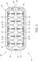
- FIG. 3 is a top view of the base 20 of the housing 12 of the heated hair setter system 10 shown in FIG. 1 , having the hair setter assemblies 14 and 16 removed for clarity.
- FIG. 4 is a front view of the base 20.
- the exemplary base 20 is a molded container that is generally cuboid in shape. Accordingly, the features of the base 20 described herein may have a draft angle associated with each wall and cavity to promote removal of the base 20 from a mold.
- the base 20 is fabricated by injection molding a thermoplastic synthetic resin suitable for use in heated hair setter system 10. However, the base 20 may be fabricated from any non-conductive material that enables the base 20 to function as described herein. Furthermore, the base 20 may be fabricated by methods other than molding, e.g., machining, and therefore may not have a draft angle associated with the features as described herein.
- the base 20 is a hollow generally cuboid-shaped structure that broadly includes a front wall 30, a rear wall 32, a left end wall 34, and an opposing right end wall 36.
- the base 20 is generally symmetrical about a central longitudinal axis 38 running substantially parallel to the front wall 30 and the rear wall 32.
- the base 20 also includes a top wall 40 and a bottom wall 42.
- An interior space 48 is defined by the defined by the walls 30, 32, 34, 36, 40, and 42.
- a plurality of access openings 18 are formed in the base 20. Each access opening 18 is open at the top wall 40 and extends downward toward the bottom wall 42 of the base 20.
- the base 20 includes five access openings 18 arranged in a side by side configuration extending along a front half 44 of the base 20, and, with respect to central longitudinal axis 38, five access openings 18 extending along a back half 46 of the base 20.
- the base 20 may include any number of access openings 18 that enable the base 20 to function as described herein.
- each one of the access openings 18 include a generally curved shaped insert opening 50 that extends through the top wall 40 to the interior space 48.
- the access openings 18 include rectangular-shaped vertical slots 52 formed through one of the front wall 30 or the rear wall 32, depending on whether the respective access opening 18 is formed along the front half 44 or the back half 46 of the base 20.
- the vertical slots 52 are provided in positions that are symmetric to each other in relation to the central longitudinal axis 38.
- the vertical slots 52 are open at the top wall 40 of the base 20, connecting to a respective insert opening 50, and extend downward a predetermined distance "D" of the height of the respective front wall 30 or the rear wall 32.
- the distance "D" is configured such that the distance is less than a height of a heater assembly contained in the housing assembly 12. This enables a portion of the front wall 30 or the rear wall 32 to extend across a bottom portion of the heater assembly and cover a bottom portion thereof.
- each of the vertical slots 52 extend widthwise a predetermined distance "W," as generally indicated at the top wall 40.
- the vertical slots 52 may be of varying widths and heights that enable the base 20 to function as described herein.
- the width "W” is narrower than the insert opening 50.
- the insert openings 50 and vertical slots 52 facilitate the insertion and removal of the hair setter assemblies 14 and 16 and limiting the amount of rotational movement of the hair setter assemblies 14 and 16.
- the narrow width "W" of the vertical slots 52 facilitate protecting a user's fingers from entering the insert opening 18 through the vertical slot 52 and contacting the heater assembly contained therein.
- the insert openings 50 and vertical slots 52 are shaped to facilitate insertion of the hair setter assemblies 14 and 16 into the base 20.
- edges of the insert openings 50 and vertical slots 52 taper outward, away from the access opening 18, to create generally tapered edges 54 or chamfers.
- tapered edges 54 are configured such that edges of the insert openings 50 and vertical slots 52 are generally smooth and free of sharp breaks, and to facilitate insertion of the hair setter assemblies 14 and 16.
- the tapered edges 54 may be defined in any configuration that permits the base 20 to function as described herein.
- FIG. 5 is an exploded isometric schematic view of the heater assembly 60 of the heated hair setter system 10 shown in FIG. 1 .
- the heater assembly 60 includes a brace 62, a plurality of vertically-standing heat delivery rails 64, and a support plate 66. As illustrated, the plurality of vertically-standing heat delivery rails 64 are parallel and longitudinally-spaced to enable the hair setter assemblies 14 and 16 to be vertically stacked in the housing 12 as shown in FIG. 1 .
- each one of the heat delivery rails 64 is formed substantially identically.
- the heat delivery rails 64 are fabricated from a generally symmetrical, elongated panel extending substantially vertically.
- the heat delivery rails 64 are substantially symmetrical from front to back, from side to side, and from end to end.
- Such a heat delivery rail configuration facilitates efficient heating of the hair setter assemblies 14 and 16 using a decreased size heat delivery rail 64.
- the symmetrical design enables a plurality of the hair setter assemblies 14 and 16 to be heated on each side of the heat delivery rail 64. As illustrated in FIG.
- the heat delivery rails 64 have an elongate, generally rectangular cross section with curved ends 120. Proximate the curved ends 120 are opposing grooves 122 on each side of the heat delivery rail 64. More specifically, the grooves 122 intersect a respective curved end 120. The grooves 122 extend axially the length of the heat delivery panel 64 transversely to the cross section of the panel.
- the heat delivery rails 64 include a hollow center portion 68 for enclosing a heating element (not shown) used for increasing the temperature of the heat delivery rails 64 during use of the heated hair setter system 10.
- the heating element is thermally coupled to the heat delivery rails 64 via the hollow center portion 68.
- the heating element is electrically coupled to a control system (not shown) via suitable wiring (not shown).
- the heating element may include, for example, electrical resistance heaters, coupled in thermal contact with the heat delivery rails 64 to heat the heat plate during use of the heated hair setter system 10.
- the heat delivery rails 64 may be fabricated from a metallic material to facilitate increased heat transfer between the heating element (not shown) and the heat delivery rails 64.
- the heat delivery rails 64 may be fabricated from any material that enables the heat delivery rails 64 to function as described herein.
- the heat delivery rails 64 may be formed as a single piece extruded component. This facilitates manufacturing efficiencies by reducing the number of components used to fabricate the heat delivery rails 64.
- the heat delivery rails 64 may be fabricated in any manner that enables the heat delivery rails 64 to function as described herein, e.g., by welding and/or otherwise bonding two heat transfer components together to form the heat delivery rails 64.
- the support plate 66 includes a plurality of rail seats 70, formed as elongate channels in support plate 66.
- the rail seats 70 are shaped to generally correspond to a cross-sectional shape of the heat delivery rails 64, thereby facilitating securely holding each heat delivery rail 64 in place when the heater assembly 60 is assembled. While the rail seats 70 are illustrated as being generally equispaced along a length of the support plate 66, it is contemplated that any spacing that enables the heater assembly 60 to function as described herein may be used.
- the support plate is fabricated from a metallic sheet material capable of supporting the heat delivery rails 64 during operation. Alternatively, the support plate 66 may be fabricated from any material that can support the heat delivery rails 64 during operation, including, e.g., plastic, ceramic, and the like.
- the brace 62 of the heater assembly 60 is generally configured to couple to an end of each heat delivery rail 64 when the heat delivery rails 64 are mounted to support plate 66.
- the brace 62 includes a central spine 72 having a plurality of equispaced, transverse rail supports 74.
- each rail support 74 is shaped to correspond to a cross-sectional shape of the heat delivery rails 64. This facilitates enabling a smooth transition from the rail support 74 to the respective heat delivery rail 64.
- each rail support 74 includes a lip 76 extending from an underside of the rail support 74. The lip 76 is sized to snuggly fit into the hollow center portion 68 of the heat delivery rail 64.
- each rail support 74 is spaced such that each rail support 74 corresponds substantially with a rail seat 70 of the support plate 66. This facilitates positioning the heat delivery rails 64 in a parallel, equispaced relationship.
- each rail support 74 is tapered inward as it extends away from the lip 76 to enable easy alignment and positioning of the hair setter assembly 14 and 16 on the heat delivery rail 64.
- the brace 62 is a molded component. Accordingly, the features of the brace 62 described herein may have a draft angle associated with each wall and cavity to promote removal of the brace 62 from a mold.
- the brace 62 is fabricated by molding a thermoplastic synthetic resin suitable for use as an insulator in heated devices. However, the brace 62 may be fabricated from any material that enables the brace 62 to function as described herein. Furthermore, the brace 62 may be fabricated by methods other than molding, e.g., machining, and therefore may not have a draft angle associated with the features as described herein.
- FIG. 6 is an exploded isometric schematic of a hair setter 80 of the hair setter assemblies 14 and 16 shown in FIG. 1 .
- the hair setter 80 is substantially cylindrical in shape and includes a body 82 and an end cap 84 located at each end of the body 82.
- the body 82 includes a cylindrically-shaped outer tube 86 and a coaxially aligned cylindrically-shaped inner tube 88, which extends the entire length of the body 82.
- the inner tube 88 and the outer tube 86 are free from direct contact along the length of the tubes. Rather, a plurality of radially extending web plates 90 are formed within the body 82 and extend between the inner tube 88 and the outer tube 86.
- the web plates 90 are in direct contact with the inner tube 88 and the outer tube 86.
- each of the web plates 90 has a length that is substantially equal to the length of the inner tube 88 and the outer tube 86.
- the body 82 includes a slot 92 defined therein.
- the slot 92 extends longitudinally along the overall axial length of the body 82 and extends inward from an outer surface 94 of the outer tube 86 through an outer surface 96 of the inner tube 88.
- the slot 92 is defined by a pair of opposing radially extending web plates 90.
- the slot 92 forms a passageway in the body 82 that has an overall width that is slightly greater than the width of the heat delivery rail 64 between the grooves 122 and smaller than an inner diameter of the inner tube 88. This enables the body 82 to be slidably coupled to the heat delivery rail 64.
- the combination of the narrower width of the slot 92 and the larger diameter of the inner tube 88 is configured to only engage the curved end 120 and opposing grooves 122 on a side of the heat delivery rail 64 in an axial direction.
- the body 82 can be slidably coupled to the heat delivery rail 64, being oriented in the axial direction of the rail and slidably moveable along the axial direction thereof.
- the body 82 is otherwise inhibited from being coupled to and decoupled from the rail in a direction transverse to the rail - which is the manner of coupling common among known hair setter systems.
- the slot 92 is configured to enable the inner tube 88 and the slot defining web plates 90 to directly engage one of the heat delivery rails 64 of the heater assembly 60.
- heat transfer between the heat delivery rail 64 and hair setter 80 is enabled.
- heat transfer from the heater assembly 60 to hair setter 80 is achieved, with the hair setter 80 being constructed to enable the heat generated by the heat delivery rails 64 of the heater assembly 60 to be absorbed by the inner tube 88 and the slot defining web plates 90, and delivered rapidly and directly to the radially extending web plates 90.
- the heat absorbed by the web plates 90 is rapidly transferred to the outer tube 86, thereby assuring rapid heating of hair setter 80 in its entirety.
- the body 82 is fabricated from a metallic material, e.g., from aluminum, to enable efficient heat transfer from the heat delivery rails 64 of the heater assembly 60 to the body 82.
- the body is fabricated by conventional extrusion equipment, facilitating the manufacturing of the body 82 in a generally inexpensive and rapidly-produced manner.
- the body 82 may be fabricated in any manufacturing operation that enables the body 82 to function as described herein, for example, by casting.
- the hair setter 80 includes an end cap 84 located at each end of the body 82.
- the end cap 84 includes a recess 100, which is sized and located so as to receive an end portion of the body 82.
- the end cap 84 also includes a plurality of ribs 102 extending radially inward from an outer edge 104 of the end cap a predetermined distance to facilitate engaging the outer surface 94 of the body 82 to locate the end cap 84 with respect to the outer tube 86 of the body 82.
- the end cap 84 includes an inner coupling component 106 configured to engage the inner tube 88 of the body 82 to facilitate locating the end cap 84 to the body 82.
- the end cap 84 includes a slot that substantially corresponds to the size and shape of the slot 92 of the body 82.
- the body 82 includes a tab (not shown) that engages with a portion of the end cap 84 to facilitate securing the end cap 84 in place.
- the end cap 84 may be secured to the body 82 by any means that enables the hair setter 80 to function as described herein.
- the end caps 84 are fabricated from an insulative material or other non-heat-conductive materials, for example, plastic, silicone-based material, resin, or the like, to facilitate reducing an amount of the heat generated by the heat delivery rails 64 from being conducted to the end caps 84.
- the end caps 84 may be fabricated from any material that enables the end caps to function as described herein.
- the end caps 84 may be fabricated from a metallic material and coated with a heat-resistive material to reduced heat conduction to an outer surface of the end caps 84.
- the body 82 of the hair setter 80 includes an outer surface treatment component 98 coupled to the outer surface 94.
- the outer surface treatment component 98 may include static dissipative coatings, ceramic materials, flocking, resin, felt, velvet, rubber, plastic, and the like, or any combinations thereof, that enable the hair setter 80 to function as described herein.
- FIG. 7 is an exploded isometric schematic of a pair of large hair setter assemblies 16 coupling with a heat delivery rail 64.
- FIG. 8 is an exploded isometric schematic of a pair of large hair setter assemblies 16 being mounted in the housing 12. While the large hair setter assembly 16 is described in detail herein, it is noted that the small hair setter assembly 14 operates substantially identically to the large hair setter assembly 16.
- the hair setter 80 is able to be quickly and easily mounted to the heat delivery rail 64 by axially aligning the hair setter 80 in longitudinally extending alignment with a curved end 120 of an edge of the heat delivery rail 64.
- a desired quantity e.g., two in the exemplary embodiment
- hair setters 80 or large hair setter assemblies 16 can be placed on the heater assembly 60 to attain the desired heating effect of the hair setters 80.
- the exemplary embodiment facilitates increasing the direct contact of hair setter 80 with the heat delivery rail 64, thereby achieving a hair setter 80 that is quickly heated to any desired temperature.
- a further advantage of the illustrated embodiment is the ability to transfer heat to a hair retention clip 110.
- the large hair setter assembly 16 includes the hair setter 80 and the retention clip 110 in combination.
- the retention clip 110 includes a spring-biased butterfly construction that enables arcuately curved grip components 112 and 114 to be pivoted away from each other by applying pressure to finger components 116 and 118 to pivot them towards each other. When the pressure is removed, the retention clip 110 pivots towards its closed configuration due to a bias spring member (not shown) incorporated therein.
- the retention clip 110 is easily coupled onto the hair setter 80 in peripherally surrounding engagement, as well as easily removed therefrom.
- the retention clip 110 is coupled to hair setter 80, as shown in FIGS. 7 and 8 .
- This facilitates heating the retention clip 110 during the heating of the hair setter 80 by the retention clip 110 directly absorbing heat through the outer tube 86 of the hair setter 80.
- the grip components 112 and 114 of the retention clip 110 are optionally fabricated from a heat conductive material, for example, a ceramic or a metal, that absorbs and retains heat.
- the finger components 116 and 118 may be coated with an insulative material or coating.
- the grip components 112 and 114 of the retention clip 110 are optionally fabricated from an insulative material, for example, a plastic, that does not absorb or retain heat.
- the grip components 112 and 114 may have inner surfaces coated or lined with a heat conductive material, for example, a ceramic or metal.
- the finger components 116 and 118 may be constructed from an insulative material.
- the embodiments of the retention clip 110 described herein facilitate reducing the conductive heat transfer to the finger components 116 and 118, enabling a user to operate the retention clip 110 without discomfort.
- the large hair setter assembly 16 is removed, i.e. slide axially off of the heat delivery rail 64 and positioned in a desired location on the hair of the user.
- the retention clip 110 is coupled to the hair setter 80 such that the slot 92 of the hair setter 80 is generally aligned with an opening created between the grip components 112 and 114 of the retention clip 110.
- This enables the hair setter 80 to be axially coupled or mounted to the heat delivery rail 64.
- the retention clip 110 is configured to be mounted to the outer surface 94 of the body 82 of the setter 80 in any rotational position to facilitate ease of use of the retention clip 110 and hair setter 80 on the hair of the user.
- the user may mount the retention clip 110 to the hair setter 80 such that one of the grip components 112 or 114 extends across or partially across the slot 92.
- This may inhibit the hair setter 80 from being coupled to or mounted on the heat delivery rail 64, or may cause a portion of one of the grip components 112 and 114 of the retention clip 110 to come into contact with the heat delivery rail 64.
- the direct contact between the heat delivery rail 64 and one of the grip components 112 and 114 of the retention clip 110 may cause heat damage to the retention clip 110.
- the access openings 18 in the housing 12, however, facilitate proper alignment of the retention clip 110 to the hair setter 80 when coupled or mounted to the heat delivery rail 64.
- FIG. 9 is a top view of the base 20 of the housing 12 illustrating one of the small hair setter assemblies 14 mounted to a heat delivery rail 64.
- the retention clip 110 is mounted to the hair setter 80 and rotated such that the finger component 116 of the retention clip 110 is in contact with an edge of the access opening 18. While the retention clip 110 is free to be mounted to the hair setter 80 in any rotation position, to mount the hair setter 80 to the heat delivery rail 64, the finger components 116 and 118 must be positioned to fit between the edges of the access opening 18.
- the grip components 112 and 114 of the retention clip 110 do not contact the heat delivery rail 64.
- the grip component 114 of the retention clip 110 is spaced a gap "G" from the heat delivery rail 64 with the finger component 116 of the retention clip 110 contacting an edge of the access opening 18.
- the access opening 18 inhibits the hair setter assemblies 14 and 16 from being mounted to the heat delivery rails 64 in a manner that enables the retention clip 110 to come into direct contact with the heat delivery rails 64.
- the vertical slot 52 of the access opening 18 is configured to inhibit the user from contacting the heat delivery rails 64 contained within the housing 12.
- the heat delivery rails 64 include parallel, opposing grooves 122 intersecting curved ends 120, i.e. a curved edge if the heat delivery rails 64.
- the web plates 90 that form the slot 92 of the hair setter 80 are configured to directly contact the grooves 122 in a sliding configuration.
- the inner tube 88 of the body 82 of the hair setter 80 is configured to directly contact the curved end 120 of the heat delivery rails 64.
- the curved ends 120 are substantially semicircular in cross-section.
- the curved end 120 and the grooves 122 cooperate with the slot 92 on the inner tube 88 of the hair setter 80 to facilitate maintaining or holding the hair setter 80 to the heat delivery rail 64, only allowing axial movement.
- the hair setter 80 must be axially slid along a length of the heat delivery rails 64 and removed from the housing 12 through the curved shaped insert opening 50.
- the user applies pressure to the finger components 116 and 118 to pivot them towards each other, which causes the curved grip components 112 and 114 to be pivoted away from each other.
- the retention clip 110 is positioned peripherally about the hair setter 80 and the pressure is removed from the finger components 116 and 118, which causes the curved grip components 112 and 114 to pivot towards each other. This enables the retention clip 110 to engage the outer surface 94 of the hair setter 80.
- the user couples the retention clip 110 the hair setter 80 such that the slot 92 of the hair setter 80 is generally aligned with the opening created between the grip components 112 and 114 of the retention clip 110.
- the combination of the retention clip 110 coupled to the hair setter 80 is described herein as the hair setter assembly 14 and/or 16.
- the user slides the hair setter assembly 14 and/or 16 on the heater assembly 60 contained in the housing 12. More specifically, the user grasps the finger components 116 and 118 and inserts the hair setter assembly 14 and/or 16 into the insert opening 50 of the access opening 18, taking care to axially align the hair setter slot 92 in longitudinally extending alignment with the curved end 120 and the grooves 122 located at an edge of the heat delivery rail 64.
- the user slides the hair setter assembly 14 and/or 16 along the heat delivery rail 64 such that the finger components 116 and 118 are positioned in the vertical slot 52 of the insert opening.
- the hair setter assembly 14 and/or 16 slides along the heat delivery rail 64 until the end cap 84 comes into contact with the support plate 66 of the heater assembly 60.
- the user may then slide a second hair setter assembly 14 and/or 16 on the same heat delivery rail 64 until its end cap 84 contacts the first hair setter assembly 14 and/or 16, thereby stacking vertically two hair setter assembly 14 and/or 16 in a single access opening 18.
- the vertical slot 52 cooperates with the retention clip finger components 116 and 118 to prevent the retention clip curved grip components 112 and 114 from making contact with the heat delivery rail 64.
- the apparatus, system, and methods described in detail herein enable a user to achieve a rapidly heated hair setter that is capable of being easily employed for rapidly absorbing heat from the heat delivery rail 64.
- the hair setter 80 is removal from the heat delivery rail 64 and used in the conventional manner. If the embodiment employing the hair retention clips 110 is employed, the heated hair clip 110 is also used in a generally conventional manner, further improving and enhancing the heat being delivered to the rolled hair fibers on the hair setter 80.
- Exemplary embodiments of an apparatus, system, and methods for a heated hair setter system are described above in detail.
- the apparatus, system, and methods described herein are not limited to the specific embodiments described, but rather, components of apparatus, systems, and/or steps of the methods may be utilized independently and separately from other components and/or steps described herein.
- the methods may also be used in combination with other heated hair styling apparatuses, systems, and methods, and are not limited to practice with only the apparatuses, systems, and methods described herein. Rather, the exemplary embodiments can be implemented and utilized in connection with many heated hair styling applications.
Landscapes
- Hair Curling (AREA)
Description
- The present disclosure relates to a heated hair setter apparatus and to a method of operating such apparatus.
- Many different types of heated hair setter systems are available for use in styling hair, such as by curling, waving, or otherwise achieving a desired look. Common among such hair styling apparatus is the ability to apply heat to a hair setter and/or a hair retention clip associated with the hair setter. The hair setter and/or a hair retention clip provide one or more heated surfaces against which the hair to be styled is contacted during styling.
- During use, at least some heated hair setter systems provide heat to the hair setter and the hair retention clip separately. These systems, however, may be large and require excess space for use and/or storage due to separately heating the hair setters and the hair retention clips, or to reduce the size of the system, the number of hair setters and the hair retention clips may be reduced. Other heated hair setter systems provide heat to the hair setters and the hair retention clips in combination. In particular, some heated hair setter systems heat the hair setter with the hair retention clip mounted to the hair setter. However, with these heated hair setter systems, a user can mount the hair retention clip to the hair setter such that the hair retention clip can directly contact the heating device. Thus, the hair retention clip can melt and/or otherwise become damaged by the heating device. There is a need, therefore, for a compact heated hair setter system that can rapidly heat a hair setter and hair retention clip assembly while preventing damage to the hair retention clip.
-
US2005/056297 A1 describes a hair curler/roller including an elongated cylindrically shaped body or core formed from a heat retaining metal, such as aluminum, the cylindrical body including a plurality of thin, interconnected wall members peripherally surrounded by a cylindrical outer wall. - Aspects of the invention are defined by the independent claims. Various optional features and embodiments are described by the dependent claims.
- We herein describe a hair setter apparatus that generally comprises a housing and a heater assembly enclosed within the housing. The heater assembly comprises a longitudinal heat delivery rail mounted in the housing and has a longitudinal axis. The longitudinal heat delivery rail includes a groove extending longitudinally along at least part of the heat delivery rail. A corresponding hair setter has a central body having opposing web plates spaced from each other to define a mounting slot extending longitudinally of the hair setter. The mounting slot is configured to engage the groove of the heat delivery rail upon mounting the hair setter thereon to slidably couple the hair setter to the heat delivery rail for sliding movement longitudinally of heat delivery rail while inhibiting decoupling of the hair setter from the heat delivery rail in a direction transverse to the rail.
- In one aspect, a hair setter apparatus comprises a housing comprising a base and a lid pivotally coupled to the base. The base comprises a top wall and a plurality of side walls together with the base and top wall defining an interior space of the housing. The base further comprises a plurality of access openings open to the interior space of the housing, with each access opening comprising an insert opening at the top wall and a vertical slot in at least one of the side walls and intersecting the insert opening at the top wall of the housing. A heater assembly is enclosed within the housing, with the heater assembly comprising a first heat delivery rail and a second heat delivery rail mounted in the housing in spaced parallel relationship to each other. Each heat delivery rail has a longitudinal edge extending parallel and generally adjacent to a respective one of the vertical slots and generally below a corresponding insert opening. The apparatus further comprises a plurality of hair setters, with each of the hair setters comprising a central body having opposing web plates spaced from each other to define a mounting slot extending longitudinally of the hair setter. The opposing web plates are configured to slidably couple the hair setter to one of the heat delivery rails along the longitudinal edge of one of the heat delivery rails. The hair setter is sized relative to the insert opening for insertion of the hair setter through the insert opening and onto the respective one of the heat delivery rails within the interior space of the housing.
- In another aspect, a method of operating such hair setter apparatus comprises coupling a retention clip to a hair setter, with the hair setter including a longitudinally extending slot. The slot is aligned with a longitudinal edge of a heat delivery rail positioned within a housing of the hair setter apparatus. The heat delivery rail includes a groove extending longitudinally adjacent the longitudinal edge of the heat delivery rail. The hair setter is slid longitudinally onto the heat delivery rail with the longitudinal edge of the heat delivery rail received in the slot of the hair setter. The hair setter is configured to seat in part in the groove of the heat delivery rail within the slot of the hair setter.
- These and other features, aspects, and advantages of the present disclosure will become better understood when the following detailed description is read with reference to the accompanying drawings in which like characters represent like parts throughout the drawings, wherein:
-
FIG. 1 is an isometric schematic of a heated hair setter system shown in an opened configuration and containing a plurality of hair setter assemblies; -
FIG. 2 is a top view of the heated hair setter system shown inFIG. 1 ; -
FIG. 3 is a top view of a base of the housing of the heated hair setter system shown inFIG. 1 , having the hair setter assemblies removed for clarity; -
FIG. 4 is a front view of the base; -
FIG. 5 is an exploded isometric schematic view of a heater assembly of the heated hair setter system shown inFIG. 1 ; -
FIG. 6 is an exploded isometric schematic of a hair setter of the hair setter assemblies shown inFIG. 1 ; -
FIG. 7 is an exploded isometric schematic of a pair of large hair setter assemblies coupling with a heat delivery rail of the heater assembly shown inFIG. 5 ; -
FIG. 8 is an exploded isometric schematic of the pair of large hair setter assemblies being mounted in the housing of the heated hair setter system shown inFIG. 1 ; and -
FIG. 9 is a top view of the base of the housing illustrating one of the small hair setter assemblies mounted to a heat delivery rail of the heater assembly shown inFIG. 5 . - Unless otherwise indicated, the drawings provided herein are meant to illustrate features of embodiments of the disclosure. These features are believed to be applicable in a wide variety of systems comprising one or more embodiments of the disclosure. As such, the drawings are not meant to include all conventional features known by those of ordinary skill in the art to be required for the practice of the embodiments disclosed herein.
- In the following specification and the claims, reference will be made to a number of terms, which shall be defined to have the following meanings. The singular forms "a," "an," and "the" include plural references unless the context clearly dictates otherwise. The terms "comprising," "including," and "having" are intended to be inclusive and mean that there may be additional elements other than the listed elements. "Optional" or "optionally" means that the subsequently described event or circumstance may or may not occur, and that the description includes instances where the event occurs and instances where it does not.
- Approximating language, as used herein throughout the specification and claims, may be applied to modify any quantitative representation that could permissibly vary without resulting in a change in the basic function to which it is related. Accordingly, a value modified by a term or terms, such as "about," "approximately," and "substantially," are not to be limited to the precise value specified. In at least some instances, the approximating language may correspond to the precision of an instrument for measuring the value. Here and throughout the specification and claims, range limitations may be combined and/or interchanged; such ranges are identified and include all the sub-ranges contained therein unless context or language indicates otherwise.
- Referring now to the drawings and in particular to
FIGS. 1 and2 ,FIG. 1 is an isometric schematic of a heatedhair setter system 10 shown in an opened configuration and containing a plurality of hair setter assemblies.FIG. 2 is a top view of the heatedhair setter system 10 shown inFIG. 1 . In the exemplary embodiment, the heated hair setter system 10-also referred to as a hair setter-includes a generally cuboid-shaped,elongate housing assembly 12 holding a plurality of hair setter assemblies, for example, smallhair setter assembly 14 and largehair setter assembly 16. It is noted that a hair setter may also be known as a hair curler or a hair roller. In the illustrated embodiment, the hair setter assemblies 14 and 16 are stacked vertically in respective pairs and are contained inaccess openings 18 formed in thehousing assembly 12. As shown inFIG. 2 , the stacked pairs ofhair setter assemblies hair setter system 10 to function as described herein. For example, in some embodiments, thehair setter assemblies hair setter assemblies housing assembly 12 could be generally circular-shaped with theaccess openings 18 formed about a perimeter of thehousing assembly 12, or arranged in other shapes that results in a different stacking array or pattern. - The
housing assembly 12 includes abase 20 and alid 22 positionable in a closed configuration to facilitate holding thehair setter assemblies housing 12, and an open configuration to facilitate access to and removal of thehair setter assemblies housing 12. As illustrated inFIGS. 1 and2 , in the exemplary embodiment, thelid 22 is rotatably coupled to thebase 20 by twohinge arms 24 coupled to respective hinge pins (not shown). Although depicted ashinge arms 24 coupled to hinge pins,lid 22 can be rotatably coupled tobase 20 using any type of hinge that enableshousing 12 to function as describe herein, e.g., using a continuous hinge, a living hinge, or the like. Alternatively, thelid 22 can be positionable onhousing 12 in any manner that enables thelid 22 to function as described herein. For example, in some embodiments, thelid 22 may be completely removable fromhousing 12 in the open configuration, and may snap or otherwise securely fasten (e.g., via a resistance member secured around the lid and housing in the closed configuration) tohousing 12 in the closed configuration. In other embodiments, thelid 22 may be configured to slide onhousing 12 between the open and closed configurations. - As shown in
FIGS. 1 and2 , in the exemplary embodiment, thehousing 12 includes a latch system to facilitate keeping thelid 22 in the closed configuration. For example, in the exemplary embodiment, thebase 20 includes acatch 26 for receiving acorresponding latch member 28 formed on thelid 22. In particular, thelatch 28 is formed on the underside of thelid 22 and depends therefrom for latching engagement with thecatch 26 formed on an end of the base 20 when thelid 22 is closed to releasably secure thelid 22 in its closed configuration. Alternatively, thelatch 28 may be attached to thebase 20 and thecatch 26 formed on thelid 22 without departing from the scope of this disclosure. It is contemplated that, in some embodiments, thehousing 12 does not include a latch system, as described herein. In such embodiments, thelid 22 may be held in place, for example, via friction coupling, through the use of resistance members, and the like. In some embodiments, thelid 22 may not be securely held in place, but may rest onhousing 12 in the closed configuration. -
FIG. 3 is a top view of thebase 20 of thehousing 12 of the heatedhair setter system 10 shown inFIG. 1 , having thehair setter assemblies FIG. 4 is a front view of thebase 20. Theexemplary base 20 is a molded container that is generally cuboid in shape. Accordingly, the features of the base 20 described herein may have a draft angle associated with each wall and cavity to promote removal of the base 20 from a mold. Thebase 20 is fabricated by injection molding a thermoplastic synthetic resin suitable for use in heatedhair setter system 10. However, thebase 20 may be fabricated from any non-conductive material that enables the base 20 to function as described herein. Furthermore, thebase 20 may be fabricated by methods other than molding, e.g., machining, and therefore may not have a draft angle associated with the features as described herein. - The
base 20 is a hollow generally cuboid-shaped structure that broadly includes afront wall 30, arear wall 32, aleft end wall 34, and an opposingright end wall 36. In the exemplary embodiment, thebase 20 is generally symmetrical about a centrallongitudinal axis 38 running substantially parallel to thefront wall 30 and therear wall 32. The base 20 also includes atop wall 40 and abottom wall 42. Aninterior space 48 is defined by the defined by thewalls access openings 18 are formed in thebase 20. Each access opening 18 is open at thetop wall 40 and extends downward toward thebottom wall 42 of thebase 20. In the exemplary embodiment, thebase 20 includes fiveaccess openings 18 arranged in a side by side configuration extending along afront half 44 of thebase 20, and, with respect to centrallongitudinal axis 38, fiveaccess openings 18 extending along aback half 46 of thebase 20. Alternatively, thebase 20 may include any number ofaccess openings 18 that enable the base 20 to function as described herein. - In the exemplary embodiment, each one of the
access openings 18 include a generally curved shaped insert opening 50 that extends through thetop wall 40 to theinterior space 48. In addition, theaccess openings 18 include rectangular-shapedvertical slots 52 formed through one of thefront wall 30 or therear wall 32, depending on whether the respective access opening 18 is formed along thefront half 44 or theback half 46 of thebase 20. Thevertical slots 52 are provided in positions that are symmetric to each other in relation to the centrallongitudinal axis 38. Thevertical slots 52 are open at thetop wall 40 of thebase 20, connecting to a respective insert opening 50, and extend downward a predetermined distance "D" of the height of the respectivefront wall 30 or therear wall 32. For example, in some embodiments, the distance "D" is configured such that the distance is less than a height of a heater assembly contained in thehousing assembly 12. This enables a portion of thefront wall 30 or therear wall 32 to extend across a bottom portion of the heater assembly and cover a bottom portion thereof. - As shown in
FIG. 4 , each of thevertical slots 52 extend widthwise a predetermined distance "W," as generally indicated at thetop wall 40. Alternatively, thevertical slots 52 may be of varying widths and heights that enable the base 20 to function as described herein. In the exemplary embodiment, with reference toFIG. 3 , it can be seen that the width "W" is narrower than theinsert opening 50. Theinsert openings 50 andvertical slots 52 facilitate the insertion and removal of thehair setter assemblies hair setter assemblies vertical slots 52 facilitate protecting a user's fingers from entering theinsert opening 18 through thevertical slot 52 and contacting the heater assembly contained therein. - In the exemplary embodiment, the
insert openings 50 andvertical slots 52 are shaped to facilitate insertion of thehair setter assemblies base 20. Referring toFIGS. 3 and4 , edges of theinsert openings 50 andvertical slots 52 taper outward, away from the access opening 18, to create generally taperededges 54 or chamfers. In the exemplary embodiment, taperededges 54 are configured such that edges of theinsert openings 50 andvertical slots 52 are generally smooth and free of sharp breaks, and to facilitate insertion of thehair setter assemblies edges 54 may be defined in any configuration that permits the base 20 to function as described herein. - As illustrated in
FIGS. 3 and4 , thebase 20 encloses other components of the heatedhair setter system 10, for example, aheater assembly 60.FIG. 5 is an exploded isometric schematic view of theheater assembly 60 of the heatedhair setter system 10 shown inFIG. 1 . Theheater assembly 60 includes abrace 62, a plurality of vertically-standing heat delivery rails 64, and asupport plate 66. As illustrated, the plurality of vertically-standing heat delivery rails 64 are parallel and longitudinally-spaced to enable thehair setter assemblies housing 12 as shown inFIG. 1 . - In the exemplary embodiment, each one of the heat delivery rails 64 is formed substantially identically. As illustrated in
FIG. 5 , the heat delivery rails 64 are fabricated from a generally symmetrical, elongated panel extending substantially vertically. For example, in the exemplary embodiment, the heat delivery rails 64 are substantially symmetrical from front to back, from side to side, and from end to end. Such a heat delivery rail configuration facilitates efficient heating of thehair setter assemblies heat delivery rail 64. The symmetrical design enables a plurality of thehair setter assemblies heat delivery rail 64. As illustrated inFIG. 5 , and discussed in more detail below, the heat delivery rails 64 have an elongate, generally rectangular cross section with curved ends 120. Proximate the curved ends 120 are opposinggrooves 122 on each side of theheat delivery rail 64. More specifically, thegrooves 122 intersect a respectivecurved end 120. Thegrooves 122 extend axially the length of theheat delivery panel 64 transversely to the cross section of the panel. - In the exemplary embodiment, the heat delivery rails 64 include a
hollow center portion 68 for enclosing a heating element (not shown) used for increasing the temperature of the heat delivery rails 64 during use of the heatedhair setter system 10. The heating element is thermally coupled to the heat delivery rails 64 via thehollow center portion 68. In one embodiment, for example, the heating element is electrically coupled to a control system (not shown) via suitable wiring (not shown). The heating element may include, for example, electrical resistance heaters, coupled in thermal contact with the heat delivery rails 64 to heat the heat plate during use of the heatedhair setter system 10. - In the exemplary embodiment, the heat delivery rails 64 may be fabricated from a metallic material to facilitate increased heat transfer between the heating element (not shown) and the heat delivery rails 64. Alternatively, the heat delivery rails 64 may be fabricated from any material that enables the heat delivery rails 64 to function as described herein. In addition, in the exemplary embodiment, the heat delivery rails 64 may be formed as a single piece extruded component. This facilitates manufacturing efficiencies by reducing the number of components used to fabricate the heat delivery rails 64. Alternatively, the heat delivery rails 64 may be fabricated in any manner that enables the heat delivery rails 64 to function as described herein, e.g., by welding and/or otherwise bonding two heat transfer components together to form the heat delivery rails 64.
- In the exemplary embodiment, the
support plate 66 includes a plurality ofrail seats 70, formed as elongate channels insupport plate 66. The rail seats 70 are shaped to generally correspond to a cross-sectional shape of the heat delivery rails 64, thereby facilitating securely holding eachheat delivery rail 64 in place when theheater assembly 60 is assembled. While the rail seats 70 are illustrated as being generally equispaced along a length of thesupport plate 66, it is contemplated that any spacing that enables theheater assembly 60 to function as described herein may be used. In the exemplary embodiment, the support plate is fabricated from a metallic sheet material capable of supporting the heat delivery rails 64 during operation. Alternatively, thesupport plate 66 may be fabricated from any material that can support the heat delivery rails 64 during operation, including, e.g., plastic, ceramic, and the like. - The
brace 62 of theheater assembly 60 is generally configured to couple to an end of eachheat delivery rail 64 when the heat delivery rails 64 are mounted to supportplate 66. As illustrated, thebrace 62 includes acentral spine 72 having a plurality of equispaced, transverse rail supports 74. As illustrated inFIG. 5 , eachrail support 74 is shaped to correspond to a cross-sectional shape of the heat delivery rails 64. This facilitates enabling a smooth transition from therail support 74 to the respectiveheat delivery rail 64. In addition, eachrail support 74 includes alip 76 extending from an underside of therail support 74. Thelip 76 is sized to snuggly fit into thehollow center portion 68 of theheat delivery rail 64. This enables thebrace 62 to securely hold eachheat delivery rail 64 in place when theheater assembly 60 is assembled. The rail supports 74 are spaced such that eachrail support 74 corresponds substantially with arail seat 70 of thesupport plate 66. This facilitates positioning the heat delivery rails 64 in a parallel, equispaced relationship. In the exemplary embodiment, eachrail support 74 is tapered inward as it extends away from thelip 76 to enable easy alignment and positioning of thehair setter assembly heat delivery rail 64. - In the exemplary embodiment, the
brace 62 is a molded component. Accordingly, the features of thebrace 62 described herein may have a draft angle associated with each wall and cavity to promote removal of thebrace 62 from a mold. Thebrace 62 is fabricated by molding a thermoplastic synthetic resin suitable for use as an insulator in heated devices. However, thebrace 62 may be fabricated from any material that enables thebrace 62 to function as described herein. Furthermore, thebrace 62 may be fabricated by methods other than molding, e.g., machining, and therefore may not have a draft angle associated with the features as described herein. -
FIG. 6 is an exploded isometric schematic of ahair setter 80 of thehair setter assemblies FIG. 1 . In the exemplary embodiment, thehair setter 80 is substantially cylindrical in shape and includes abody 82 and anend cap 84 located at each end of thebody 82. Thebody 82 includes a cylindrically-shapedouter tube 86 and a coaxially aligned cylindrically-shaped inner tube 88, which extends the entire length of thebody 82. As illustrated inFIG. 6 , the inner tube 88 and theouter tube 86 are free from direct contact along the length of the tubes. Rather, a plurality of radially extendingweb plates 90 are formed within thebody 82 and extend between the inner tube 88 and theouter tube 86. Theweb plates 90 are in direct contact with the inner tube 88 and theouter tube 86. In addition, each of theweb plates 90 has a length that is substantially equal to the length of the inner tube 88 and theouter tube 86. - In the exemplary embodiment, the
body 82 includes aslot 92 defined therein. Theslot 92 extends longitudinally along the overall axial length of thebody 82 and extends inward from anouter surface 94 of theouter tube 86 through anouter surface 96 of the inner tube 88. Theslot 92 is defined by a pair of opposing radially extendingweb plates 90. Theslot 92 forms a passageway in thebody 82 that has an overall width that is slightly greater than the width of theheat delivery rail 64 between thegrooves 122 and smaller than an inner diameter of the inner tube 88. This enables thebody 82 to be slidably coupled to theheat delivery rail 64. In particular, the combination of the narrower width of theslot 92 and the larger diameter of the inner tube 88 is configured to only engage thecurved end 120 and opposinggrooves 122 on a side of theheat delivery rail 64 in an axial direction. Thus, thebody 82 can be slidably coupled to theheat delivery rail 64, being oriented in the axial direction of the rail and slidably moveable along the axial direction thereof. Thebody 82 is otherwise inhibited from being coupled to and decoupled from the rail in a direction transverse to the rail - which is the manner of coupling common among known hair setter systems. - Furthermore, the
slot 92 is configured to enable the inner tube 88 and the slot definingweb plates 90 to directly engage one of the heat delivery rails 64 of theheater assembly 60. By providing direct engagement or contact between the inner tube 88 and the slot definingweb plates 90 and theheat delivery rail 64, heat transfer between theheat delivery rail 64 andhair setter 80 is enabled. Thus, heat transfer from theheater assembly 60 tohair setter 80 is achieved, with thehair setter 80 being constructed to enable the heat generated by the heat delivery rails 64 of theheater assembly 60 to be absorbed by the inner tube 88 and the slot definingweb plates 90, and delivered rapidly and directly to the radially extendingweb plates 90. The heat absorbed by theweb plates 90 is rapidly transferred to theouter tube 86, thereby assuring rapid heating ofhair setter 80 in its entirety. - In the exemplary embodiment, the
body 82 is fabricated from a metallic material, e.g., from aluminum, to enable efficient heat transfer from the heat delivery rails 64 of theheater assembly 60 to thebody 82. In addition, the body is fabricated by conventional extrusion equipment, facilitating the manufacturing of thebody 82 in a generally inexpensive and rapidly-produced manner. Alternatively, thebody 82 may be fabricated in any manufacturing operation that enables thebody 82 to function as described herein, for example, by casting. - In addition, the
hair setter 80 includes anend cap 84 located at each end of thebody 82. Theend cap 84 includes arecess 100, which is sized and located so as to receive an end portion of thebody 82. Theend cap 84 also includes a plurality ofribs 102 extending radially inward from anouter edge 104 of the end cap a predetermined distance to facilitate engaging theouter surface 94 of thebody 82 to locate theend cap 84 with respect to theouter tube 86 of thebody 82. In addition, theend cap 84 includes aninner coupling component 106 configured to engage the inner tube 88 of thebody 82 to facilitate locating theend cap 84 to thebody 82. Theend cap 84 includes a slot that substantially corresponds to the size and shape of theslot 92 of thebody 82. To secure theend cap 84 to thebody 82, thebody 82 includes a tab (not shown) that engages with a portion of theend cap 84 to facilitate securing theend cap 84 in place. Alternatively, theend cap 84 may be secured to thebody 82 by any means that enables thehair setter 80 to function as described herein. - In the exemplary embodiment, the end caps 84 are fabricated from an insulative material or other non-heat-conductive materials, for example, plastic, silicone-based material, resin, or the like, to facilitate reducing an amount of the heat generated by the heat delivery rails 64 from being conducted to the end caps 84. Alternatively, the end caps 84 may be fabricated from any material that enables the end caps to function as described herein. For example, in one, embodiment, the end caps 84 may be fabricated from a metallic material and coated with a heat-resistive material to reduced heat conduction to an outer surface of the end caps 84.
- In the exemplary embodiment, as illustrated in
FIG. 6 , thebody 82 of thehair setter 80 includes an outersurface treatment component 98 coupled to theouter surface 94. For example, the outersurface treatment component 98 may include static dissipative coatings, ceramic materials, flocking, resin, felt, velvet, rubber, plastic, and the like, or any combinations thereof, that enable thehair setter 80 to function as described herein. -
FIG. 7 is an exploded isometric schematic of a pair of largehair setter assemblies 16 coupling with aheat delivery rail 64.FIG. 8 is an exploded isometric schematic of a pair of largehair setter assemblies 16 being mounted in thehousing 12. While the largehair setter assembly 16 is described in detail herein, it is noted that the smallhair setter assembly 14 operates substantially identically to the largehair setter assembly 16. - In the exemplary embodiment, the
hair setter 80 is able to be quickly and easily mounted to theheat delivery rail 64 by axially aligning thehair setter 80 in longitudinally extending alignment with acurved end 120 of an edge of theheat delivery rail 64. By placing eachadditional hair setter 80, or largehair setter assembly 16, in a stacked arrangement on theheat delivery rail 64 in a substantially similar manner, a desired quantity (e.g., two in the exemplary embodiment) ofhair setters 80 or largehair setter assemblies 16 can be placed on theheater assembly 60 to attain the desired heating effect of thehair setters 80. - During operation, with the inner tube 88 and the slot defining
web plates 90 in direct engagement with theheat delivery rail 64 of theheater assembly 60, as is described herein, the heat generated byheat delivery rail 64 is quickly transferred directly to the inner tube 88 and the slot definingweb plates 90, theother web plates 90, and theouter tube 86. Thus, the exemplary embodiment facilitates increasing the direct contact ofhair setter 80 with theheat delivery rail 64, thereby achieving ahair setter 80 that is quickly heated to any desired temperature. - In addition, a further advantage of the illustrated embodiment is the ability to transfer heat to a
hair retention clip 110. As shown inFIGS. 7 and8 , the largehair setter assembly 16 includes thehair setter 80 and theretention clip 110 in combination. Theretention clip 110 includes a spring-biased butterfly construction that enables arcuatelycurved grip components components retention clip 110 pivots towards its closed configuration due to a bias spring member (not shown) incorporated therein. Thus, theretention clip 110 is easily coupled onto thehair setter 80 in peripherally surrounding engagement, as well as easily removed therefrom. - In the exemplary embodiment, during heating of the
hair setter 80, theretention clip 110 is coupled tohair setter 80, as shown inFIGS. 7 and8 . This facilitates heating theretention clip 110 during the heating of thehair setter 80 by theretention clip 110 directly absorbing heat through theouter tube 86 of thehair setter 80. In some embodiments, thegrip components retention clip 110 are optionally fabricated from a heat conductive material, for example, a ceramic or a metal, that absorbs and retains heat. To facilitate handling theheated retention clip 110 in such embodiments, thefinger components grip components retention clip 110 are optionally fabricated from an insulative material, for example, a plastic, that does not absorb or retain heat. In such embodiments, thegrip components heated retention clip 110, thefinger components - The embodiments of the
retention clip 110 described herein facilitate reducing the conductive heat transfer to thefinger components retention clip 110 without discomfort. This results in the largehair setter assembly 16, including thehair setter 80 and theretention clip 110, being quickly and efficiently heated by theheater assembly 60. After a heating cycle is completed, the largehair setter assembly 16 is removed, i.e. slide axially off of theheat delivery rail 64 and positioned in a desired location on the hair of the user. - As illustrated in
FIG. 7 , theretention clip 110 is coupled to thehair setter 80 such that theslot 92 of thehair setter 80 is generally aligned with an opening created between thegrip components retention clip 110. This enables thehair setter 80 to be axially coupled or mounted to theheat delivery rail 64. Theretention clip 110, however, is configured to be mounted to theouter surface 94 of thebody 82 of thesetter 80 in any rotational position to facilitate ease of use of theretention clip 110 andhair setter 80 on the hair of the user. Thus, the user may mount theretention clip 110 to thehair setter 80 such that one of thegrip components slot 92. This may inhibit thehair setter 80 from being coupled to or mounted on theheat delivery rail 64, or may cause a portion of one of thegrip components retention clip 110 to come into contact with theheat delivery rail 64. The direct contact between theheat delivery rail 64 and one of thegrip components retention clip 110 may cause heat damage to theretention clip 110. Theaccess openings 18 in thehousing 12, however, facilitate proper alignment of theretention clip 110 to thehair setter 80 when coupled or mounted to theheat delivery rail 64. -
FIG. 9 is a top view of thebase 20 of thehousing 12 illustrating one of the smallhair setter assemblies 14 mounted to aheat delivery rail 64. In the illustrated configuration, theretention clip 110 is mounted to thehair setter 80 and rotated such that thefinger component 116 of theretention clip 110 is in contact with an edge of theaccess opening 18. While theretention clip 110 is free to be mounted to thehair setter 80 in any rotation position, to mount thehair setter 80 to theheat delivery rail 64, thefinger components access opening 18. When theretention clip 110 is rotated to its limit, i.e., contacting the edges of the access opening 18, thegrip components retention clip 110 do not contact theheat delivery rail 64. For example, as illustrated, thegrip component 114 of theretention clip 110 is spaced a gap "G" from theheat delivery rail 64 with thefinger component 116 of theretention clip 110 contacting an edge of theaccess opening 18. Thus, the access opening 18 inhibits thehair setter assemblies retention clip 110 to come into direct contact with the heat delivery rails 64. In addition, thevertical slot 52 of the access opening 18 is configured to inhibit the user from contacting the heat delivery rails 64 contained within thehousing 12. - In addition, as illustrated in
FIG. 9 and as described herein, the heat delivery rails 64 include parallel, opposinggrooves 122 intersecting curved ends 120, i.e. a curved edge if the heat delivery rails 64. Theweb plates 90 that form theslot 92 of thehair setter 80 are configured to directly contact thegrooves 122 in a sliding configuration. The inner tube 88 of thebody 82 of thehair setter 80 is configured to directly contact thecurved end 120 of the heat delivery rails 64. In the exemplary embodiment, the curved ends 120 are substantially semicircular in cross-section. Thus, as can been seen, thecurved end 120 and thegrooves 122 cooperate with theslot 92 on the inner tube 88 of thehair setter 80 to facilitate maintaining or holding thehair setter 80 to theheat delivery rail 64, only allowing axial movement. Thus, thehair setter 80 must be axially slid along a length of the heat delivery rails 64 and removed from thehousing 12 through the curved shapedinsert opening 50. - During operation, the user applies pressure to the
finger components curved grip components retention clip 110 is positioned peripherally about thehair setter 80 and the pressure is removed from thefinger components curved grip components retention clip 110 to engage theouter surface 94 of thehair setter 80. The user couples theretention clip 110 thehair setter 80 such that theslot 92 of thehair setter 80 is generally aligned with the opening created between thegrip components retention clip 110. The combination of theretention clip 110 coupled to thehair setter 80 is described herein as thehair setter assembly 14 and/or 16. - The user slides the
hair setter assembly 14 and/or 16 on theheater assembly 60 contained in thehousing 12. More specifically, the user grasps thefinger components hair setter assembly 14 and/or 16 into the insert opening 50 of the access opening 18, taking care to axially align thehair setter slot 92 in longitudinally extending alignment with thecurved end 120 and thegrooves 122 located at an edge of theheat delivery rail 64. The user slides thehair setter assembly 14 and/or 16 along theheat delivery rail 64 such that thefinger components vertical slot 52 of the insert opening. Thehair setter assembly 14 and/or 16 slides along theheat delivery rail 64 until theend cap 84 comes into contact with thesupport plate 66 of theheater assembly 60. The user may then slide a secondhair setter assembly 14 and/or 16 on the sameheat delivery rail 64 until itsend cap 84 contacts the firsthair setter assembly 14 and/or 16, thereby stacking vertically twohair setter assembly 14 and/or 16 in asingle access opening 18. As described herein, thevertical slot 52 cooperates with the retentionclip finger components grip components heat delivery rail 64. - The apparatus, system, and methods described in detail herein enable a user to achieve a rapidly heated hair setter that is capable of being easily employed for rapidly absorbing heat from the
heat delivery rail 64. Oncehair setter 80 has been heated to a desired level, thehair setter 80 is removal from theheat delivery rail 64 and used in the conventional manner. If the embodiment employing the hair retention clips 110 is employed, theheated hair clip 110 is also used in a generally conventional manner, further improving and enhancing the heat being delivered to the rolled hair fibers on thehair setter 80. - Exemplary embodiments of an apparatus, system, and methods for a heated hair setter system are described above in detail. The apparatus, system, and methods described herein are not limited to the specific embodiments described, but rather, components of apparatus, systems, and/or steps of the methods may be utilized independently and separately from other components and/or steps described herein. For example, the methods may also be used in combination with other heated hair styling apparatuses, systems, and methods, and are not limited to practice with only the apparatuses, systems, and methods described herein. Rather, the exemplary embodiments can be implemented and utilized in connection with many heated hair styling applications.
- Although specific features of various embodiments of the disclosure may be shown in some drawings and not in others, this is for convenience only. In accordance with the principles of the disclosure, any feature of a drawing may be referenced and/or claimed in combination with any feature of any other drawing.
- This written description uses examples to disclose the embodiments, including the best mode, and also to enable any person skilled in the art to practice the embodiments, including making and using any devices or systems and performing any incorporated methods. The patentable scope of the disclosure is defined by the claims, and may include other examples that occur to those skilled in the art. Such other examples are intended to be within the scope of the claims if they have structural elements that do not differ from the literal language of the claims, or if they include equivalent structural elements with insubstantial differences from the literal languages of the claims.
Claims (15)
- A hair setter apparatus (10) comprising:a housing (12) comprising a base (20) and a lid (22), the base (20) comprising a top wall (40) and a plurality of side walls (30, 32, 34, 36), the base (20) defining an interior space of the housing (12), the base further comprising a plurality of access openings open to the interior space of the housing (12), each access opening comprising an insert opening at the top wall (40) and a vertical slot in at least one of the side walls (30, 32, 34, 36) and intersecting the insert opening at the top wall (40) of the housing (12);a heater assembly (60) enclosed within the housing (12), the heater assembly (60) comprising a first heat delivery rail (64) and a second heat delivery rail (64) mounted in the housing (12) in spaced parallel relationship to each other, each heat delivery rail (64) having a longitudinal edge extending parallel and generally adjacent to a respective one of the vertical slots and generally below a corresponding insert opening; anda plurality of hair setters (80), each of the hair setters (80) comprising a central body (82) having opposing web plates (90) spaced from each other to define a mounting slot (92) extending longitudinally of the hair setter (80), the opposing web plates (90) being configured to slidably couple the hair setter (80) to one of the heat delivery rails (64) along the longitudinal edge of said one of the heat delivery rails (64), the hair setter (80) being sized relative to the insert opening for insertion of the hair setter (80) through the insert opening and onto the respective one of the heat delivery rails (64) within the interior space of the housing (12).
- The hair setter apparatus (10) in accordance with claim 1 further comprising a plurality of retention clips (110) each configured to be removably coupled to a respective one of the hair setters (80) in peripherally surrounding engagement thereof.
- The hair setter apparatus (10) in accordance with claim 2, wherein each retention clip (110) comprises a pair of opposing finger components (116, 118) and a pair of curved grip components (112, 114), the pair of curved grip components (112, 114) engaging the hair setter (80) when coupled to the hair setter (80), the pair of finger components (116, 118) extending through the vertical slot of said one of the side walls when the hair setter (80) is coupled to one of the heat delivery rails (64).
- The hair setter apparatus (10) in accordance with claim 3, wherein the vertical slot has a width configured to inhibit the hair setter (80) against removal from the housing (12) through the vertical slot.
- The hair setter apparatus (10) in accordance with claim 1, wherein the insert opening and the vertical slot comprise tapered edges to facilitate insertion of the hair setters (80) into the interior space of the housing (12).
- The hair setter apparatus (10) in accordance with claim 1, wherein at least two hair setters (80) can be stacked one on top of the other along the longitudinal edge of the heat delivery rail (64).
- The hair setter apparatus (10) in accordance with claim 1, wherein the mounting slot extends longitudinally along an entire length of the hair setter (80).
- The hair setter apparatus (10) in accordance with claim 1, wherein the central body (82) further comprises an inner tube (88) and a cylindrically-shaped outer tube (86) concentric with the inner tube (88), wherein the web plates (90) couple the inner tube (86) to the outer tube (88).
- The hair setter apparatus (10) in accordance with claim 8, wherein the central body (82) comprises an outer surface treatment component (98) coupled to an outer surface of the outer tube (86).
- The hair setter apparatus (10) in accordance with claim 9, wherein the outer surface treatment component (98) is selected from the group consisting of a static dissipative coating, ceramic material, flocking, resin, felt, velvet, rubber, plastic, and combinations thereof.
- The hair setter apparatus (10) in accordance with claim 8, wherein the mounting slot defined by the opposed web plates (90) has a width, the inner tube (88) having an inner diameter greater than the width of the mounting slot.
- The hair setter apparatus (10) in accordance with claim 1, wherein the central body (82) is constructed from a metallic material.
- The hair setter apparatus (10) in accordance with claim 1, wherein the first heat delivery rail (64) includes a groove (122) extending longitudinally along at least part of the heat delivery rail (64).
- The hair setter apparatus (10) in accordance with claim 1, wherein the first heat delivery rail (64) is symmetrical about a longitudinal axis thereof and has pair of opposite edges, the first heat delivery rail (64) comprising a first groove (122) extending longitudinally adjacent one of said edges and a second groove (122) extending longitudinally adjacent the opposite one of said edges.
- A method of operating the hair setter apparatus (10) of any one of the preceding claims, the method comprising coupling a retention clip (110) to a hair setter (80), the hair setter (80) comprising a central body having opposing web plates spaced from each other to define a mounting slot extending longitudinally of the hair setter;inserting the hair setter through an access opening of a housing (12), the housing (12) comprising a base (20) and a lid (22), the base (20) comprising a top wall (40) and a plurality of side walls (30, 32, 34, 36), the base (20) defining an interior space of the housing (12), the base (20) further comprising a plurality of the access openings open to the interior space of the housing (12), each access opening comprising an insert opening at the top wall (40) and a vertical slot in at least one of the side walls (30, 32, 34, 36) and intersecting the insert opening at the top wall of the housing (12), wherein the hair setter (80) is sized relative to the insert opening for insertion of the hair setter (80) through the insert opening and onto a heat delivery rail (64) within the interior space of the housing (12); andslidably coupling the hair setter (80) onto the heat delivery rail (64) mounted in the housing (12), the heat delivery rail (64) having a longitudinal edge extending parallel and generally adjacent to the vertical slot and generally below the insert opening.
Applications Claiming Priority (3)
| Application Number | Priority Date | Filing Date | Title |
|---|---|---|---|
| US201662336992P | 2016-05-16 | 2016-05-16 | |
| PCT/US2017/032621 WO2017200909A1 (en) | 2016-05-16 | 2017-05-15 | Heated hair setter apparatus and method |
| EP17799938.0A EP3457885B1 (en) | 2016-05-16 | 2017-05-15 | Heated hair setter apparatus and method |
Related Parent Applications (2)
| Application Number | Title | Priority Date | Filing Date |
|---|---|---|---|
| EP17799938.0A Division EP3457885B1 (en) | 2016-05-16 | 2017-05-15 | Heated hair setter apparatus and method |
| EP17799938.0A Division-Into EP3457885B1 (en) | 2016-05-16 | 2017-05-15 | Heated hair setter apparatus and method |
Publications (2)
| Publication Number | Publication Date |
|---|---|
| EP3785565A1 EP3785565A1 (en) | 2021-03-03 |
| EP3785565B1 true EP3785565B1 (en) | 2023-07-05 |
Family
ID=60325438
Family Applications (2)
| Application Number | Title | Priority Date | Filing Date |
|---|---|---|---|
| EP20198882.1A Active EP3785565B1 (en) | 2016-05-16 | 2017-05-15 | Heated hair setter apparatus and method |
| EP17799938.0A Active EP3457885B1 (en) | 2016-05-16 | 2017-05-15 | Heated hair setter apparatus and method |
Family Applications After (1)
| Application Number | Title | Priority Date | Filing Date |
|---|---|---|---|
| EP17799938.0A Active EP3457885B1 (en) | 2016-05-16 | 2017-05-15 | Heated hair setter apparatus and method |
Country Status (3)
| Country | Link |
|---|---|
| US (2) | US10524553B2 (en) |
| EP (2) | EP3785565B1 (en) |
| WO (1) | WO2017200909A1 (en) |
Families Citing this family (1)
| Publication number | Priority date | Publication date | Assignee | Title |
|---|---|---|---|---|
| US12042034B2 (en) | 2020-10-14 | 2024-07-23 | Pamela J. Brooks | Heat-retaining clips for creating textured waves in hair |
Family Cites Families (34)
| Publication number | Priority date | Publication date | Assignee | Title |
|---|---|---|---|---|
| US2159358A (en) | 1939-05-23 | Hair waving device | ||
| US1980475A (en) | 1933-01-03 | 1934-11-13 | Us Appliance Corp | Hair waving apparatus |
| US2165552A (en) | 1936-12-22 | 1939-07-11 | Anthon G Johnson | Permanent waving apparatus |
| US2541639A (en) | 1947-02-07 | 1951-02-13 | Nestle Le Mur Company | Electric preheater for hair curlers |
| US2517253A (en) | 1947-08-20 | 1950-08-01 | Philip D Spaeth | Hair curling clip heater |
| US2509747A (en) | 1949-01-18 | 1950-05-30 | Nestle Lemur Company | Electric preheater for permanent waving |
| US2824367A (en) | 1955-06-22 | 1958-02-25 | Arthur C Mcwilliams | Dry shaver having combination suction and adjustable cutting means |
| US3089236A (en) | 1960-05-10 | 1963-05-14 | Joseph A Galvao | Electric shaver with improved tubular comb and rotor type cutting head |
| US3116551A (en) | 1960-09-07 | 1964-01-07 | Nicholas T Anton | Rotary shaver |
| US3119180A (en) | 1961-12-20 | 1964-01-28 | Bruecker John | Shear plate and cutter assembly for rotary-type dry shaver |
| NL296894A (en) | 1963-08-20 | |||
| BE759429A (en) | 1969-12-05 | 1971-04-30 | Carinthia Elektrogeraete Gmbh | DRY RAZOR |
| US3889097A (en) | 1973-07-26 | 1975-06-10 | Curtis Helene Ind Inc | Permanent waving machine |
| DE2852990C2 (en) | 1978-12-07 | 1982-02-18 | Philips Patentverwaltung Gmbh, 2000 Hamburg | "Pre-knife as a hair pulling element for cutting knives of electrically powered dry shavers" |
| US5294777A (en) | 1992-06-18 | 1994-03-15 | Clairol, Incorporated | Hair clip for heating and shaping root-area hair perpendicular to the scalp and an electric heating unit for heating the clips |
| US5522407A (en) | 1992-10-24 | 1996-06-04 | Uptown Products, Inc. | Heated hair clip |
| US5301425A (en) | 1992-11-04 | 1994-04-12 | Warner-Lambert Company | Rotary powered dynamic shaving system with shaving aid |
| JP3521089B2 (en) | 1993-02-12 | 2004-04-19 | 株式会社泉精器製作所 | Electric razor |
| USD388903S (en) | 1994-12-02 | 1998-01-06 | Martha Kelsey | Heating unit for chair clips |
| US6114661A (en) * | 1999-05-06 | 2000-09-05 | Conair Corporation | Hair curler with slot adapted to receive a rail-like heat conductor |
| US6084210A (en) * | 1999-10-04 | 2000-07-04 | Windmere Corporation | Rotatable hair curler set with electric heater |
| US6499195B1 (en) | 2001-09-13 | 2002-12-31 | Raymond Electric (China) Ltd. | Hair curler heating appliance |
| US7516745B2 (en) * | 2003-09-15 | 2009-04-14 | Rovcal, Inc. | Heat delivery system for heated hair rollers/curlers and clips |
| JP2005185827A (en) | 2003-12-03 | 2005-07-14 | Izumi Products Co | Electric rotary shaver |
| MXPA06011371A (en) | 2004-04-10 | 2006-12-20 | Henkel Kgaa | Hair roller. |
| JP2007135991A (en) | 2005-11-21 | 2007-06-07 | Izumi Products Co | Rotary electric shaver |
| JP5006595B2 (en) | 2006-08-04 | 2012-08-22 | 株式会社泉精器製作所 | Inner blade for rotary shaver and rotary shaver using the same |
| US8327860B2 (en) | 2007-03-27 | 2012-12-11 | Linda Flowers | Heat retaining hair curling system and method of styling |
| US20090165811A1 (en) | 2007-12-13 | 2009-07-02 | Israel Harry Zimmerman | Hair curling system |
| US20100116286A1 (en) * | 2008-10-02 | 2010-05-13 | O'rourke Michael John | Hair curler system |
| US7989735B1 (en) | 2010-11-19 | 2011-08-02 | Linda Flowers | Heating apparatus for heat retaining hair clips |
| USD648894S1 (en) | 2010-11-19 | 2011-11-15 | Linda Flowers | Heating apparatus for a heat retaining hair clip |
| US20130133684A1 (en) | 2011-11-28 | 2013-05-30 | Carol Ann Sinnott | Hot Clip |
| US20140116461A1 (en) | 2012-10-26 | 2014-05-01 | Rie OISHI | Heating apparatus for heating hair curlers |
-
2017
- 2017-05-15 EP EP20198882.1A patent/EP3785565B1/en active Active
- 2017-05-15 US US16/096,584 patent/US10524553B2/en active Active
- 2017-05-15 WO PCT/US2017/032621 patent/WO2017200909A1/en unknown
- 2017-05-15 EP EP17799938.0A patent/EP3457885B1/en active Active
-
2019
- 2019-11-26 US US16/696,413 patent/US11272772B2/en active Active
Also Published As
| Publication number | Publication date |
|---|---|
| US20190133286A1 (en) | 2019-05-09 |
| US20200093239A1 (en) | 2020-03-26 |
| EP3457885A1 (en) | 2019-03-27 |
| EP3457885A4 (en) | 2019-11-06 |
| US10524553B2 (en) | 2020-01-07 |
| EP3785565A1 (en) | 2021-03-03 |
| EP3457885B1 (en) | 2020-11-11 |
| WO2017200909A1 (en) | 2017-11-23 |
| US11272772B2 (en) | 2022-03-15 |
Similar Documents
| Publication | Publication Date | Title |
|---|---|---|
| ES2808916T3 (en) | Hair treatment device | |
| US7540289B2 (en) | Hair styling device and method of operation | |
| US7341064B2 (en) | Toothed heated hair styling device and method of manufacture | |
| US11272772B2 (en) | Heated hair setter apparatus and method | |
| BRPI0800776A2 (en) | hair appliance | |
| ES2865288T3 (en) | Hair treatment device featuring a removable oscillating pressure element | |
| WO2016060313A1 (en) | Tube container provided with metal applicator | |
| BR112014016425B1 (en) | AEROSOL GENERATION SYSTEM | |
| JP2008253745A (en) | Hair styling instrument | |
| JP6651631B2 (en) | Hair treatment device | |
| US4584462A (en) | Hairsetter for electrically heating flexible hair curlers | |
| EP1667547A2 (en) | Heat delivery system for heated hair rollers/curlers and clips | |
| US10743633B2 (en) | Dual function hair styling tool holder | |
| KR101750012B1 (en) | Hair clip | |
| US20130152961A1 (en) | Expandable Hot Rollers | |
| US5981908A (en) | Heating apparatus for vertically stacked hair rollers | |
| CN106536025B (en) | Device for separation and collection of plasma | |
| CN108472819A (en) | Razor head | |
| CN218852132U (en) | Electric heating comb | |
| US4548218A (en) | Hair curling roller | |
| CN212922472U (en) | Clip taking and placing device | |
| US9265322B2 (en) | Hair pin opener apparatus and system | |
| CN212394143U (en) | Anti-scald hair straightener | |
| KR101788526B1 (en) | Hair froler heating device | |
| JP2001037528A (en) | Hair curler |
Legal Events
| Date | Code | Title | Description |
|---|---|---|---|
| PUAI | Public reference made under article 153(3) epc to a published international application that has entered the european phase |
Free format text: ORIGINAL CODE: 0009012 |
|
| STAA | Information on the status of an ep patent application or granted ep patent |
Free format text: STATUS: THE APPLICATION HAS BEEN PUBLISHED |
|
| AC | Divisional application: reference to earlier application |
Ref document number: 3457885 Country of ref document: EP Kind code of ref document: P |
|
| AK | Designated contracting states |
Kind code of ref document: A1 Designated state(s): AL AT BE BG CH CY CZ DE DK EE ES FI FR GB GR HR HU IE IS IT LI LT LU LV MC MK MT NL NO PL PT RO RS SE SI SK SM TR |
|
| STAA | Information on the status of an ep patent application or granted ep patent |
Free format text: STATUS: REQUEST FOR EXAMINATION WAS MADE |
|
| 17P | Request for examination filed |
Effective date: 20210901 |
|
| RBV | Designated contracting states (corrected) |
Designated state(s): AL AT BE BG CH CY CZ DE DK EE ES FI FR GB GR HR HU IE IS IT LI LT LU LV MC MK MT NL NO PL PT RO RS SE SI SK SM TR |
|
| STAA | Information on the status of an ep patent application or granted ep patent |
Free format text: STATUS: EXAMINATION IS IN PROGRESS |
|
| RIC1 | Information provided on ipc code assigned before grant |
Ipc: A45D 2/14 20060101ALI20210920BHEP Ipc: A45D 4/16 20060101ALI20210920BHEP Ipc: A45D 4/12 20060101ALI20210920BHEP Ipc: A45D 4/06 20060101ALI20210920BHEP Ipc: A45D 2/12 20060101ALI20210920BHEP Ipc: A45D 2/10 20060101ALI20210920BHEP Ipc: A45D 1/20 20060101ALI20210920BHEP Ipc: A45D 1/04 20060101ALI20210920BHEP Ipc: A45D 1/02 20060101ALI20210920BHEP Ipc: A45D 2/36 20060101AFI20210920BHEP |
|
| 17Q | First examination report despatched |
Effective date: 20211015 |
|
| GRAP | Despatch of communication of intention to grant a patent |
Free format text: ORIGINAL CODE: EPIDOSNIGR1 |
|
| STAA | Information on the status of an ep patent application or granted ep patent |
Free format text: STATUS: GRANT OF PATENT IS INTENDED |
|
| INTG | Intention to grant announced |
Effective date: 20230109 |
|
| GRAS | Grant fee paid |
Free format text: ORIGINAL CODE: EPIDOSNIGR3 |
|
| GRAA | (expected) grant |
Free format text: ORIGINAL CODE: 0009210 |
|
| STAA | Information on the status of an ep patent application or granted ep patent |
Free format text: STATUS: THE PATENT HAS BEEN GRANTED |
|
| AC | Divisional application: reference to earlier application |
Ref document number: 3457885 Country of ref document: EP Kind code of ref document: P |
|
| AK | Designated contracting states |
Kind code of ref document: B1 Designated state(s): AL AT BE BG CH CY CZ DE DK EE ES FI FR GB GR HR HU IE IS IT LI LT LU LV MC MK MT NL NO PL PT RO RS SE SI SK SM TR |
|
| REG | Reference to a national code |
Ref country code: CH Ref legal event code: EP |
|
| REG | Reference to a national code |
Ref country code: AT Ref legal event code: REF Ref document number: 1583997 Country of ref document: AT Kind code of ref document: T Effective date: 20230715 |
|
| REG | Reference to a national code |
Ref country code: DE Ref legal event code: R096 Ref document number: 602017071097 Country of ref document: DE |
|
| REG | Reference to a national code |
Ref country code: IE Ref legal event code: FG4D |
|
| REG | Reference to a national code |
Ref country code: LT Ref legal event code: MG9D |
|
| REG | Reference to a national code |
Ref country code: NL Ref legal event code: MP Effective date: 20230705 |
|
| REG | Reference to a national code |
Ref country code: AT Ref legal event code: MK05 Ref document number: 1583997 Country of ref document: AT Kind code of ref document: T Effective date: 20230705 |
|
| PG25 | Lapsed in a contracting state [announced via postgrant information from national office to epo] |
Ref country code: NL Free format text: LAPSE BECAUSE OF FAILURE TO SUBMIT A TRANSLATION OF THE DESCRIPTION OR TO PAY THE FEE WITHIN THE PRESCRIBED TIME-LIMIT Effective date: 20230705 |
|
| PG25 | Lapsed in a contracting state [announced via postgrant information from national office to epo] |
Ref country code: GR Free format text: LAPSE BECAUSE OF FAILURE TO SUBMIT A TRANSLATION OF THE DESCRIPTION OR TO PAY THE FEE WITHIN THE PRESCRIBED TIME-LIMIT Effective date: 20231006 |
|
| PG25 | Lapsed in a contracting state [announced via postgrant information from national office to epo] |
Ref country code: ES Free format text: LAPSE BECAUSE OF FAILURE TO SUBMIT A TRANSLATION OF THE DESCRIPTION OR TO PAY THE FEE WITHIN THE PRESCRIBED TIME-LIMIT Effective date: 20230705 |
|
| PG25 | Lapsed in a contracting state [announced via postgrant information from national office to epo] |
Ref country code: IS Free format text: LAPSE BECAUSE OF FAILURE TO SUBMIT A TRANSLATION OF THE DESCRIPTION OR TO PAY THE FEE WITHIN THE PRESCRIBED TIME-LIMIT Effective date: 20231105 |
|
| PG25 | Lapsed in a contracting state [announced via postgrant information from national office to epo] |
Ref country code: SE Free format text: LAPSE BECAUSE OF FAILURE TO SUBMIT A TRANSLATION OF THE DESCRIPTION OR TO PAY THE FEE WITHIN THE PRESCRIBED TIME-LIMIT Effective date: 20230705 Ref country code: RS Free format text: LAPSE BECAUSE OF FAILURE TO SUBMIT A TRANSLATION OF THE DESCRIPTION OR TO PAY THE FEE WITHIN THE PRESCRIBED TIME-LIMIT Effective date: 20230705 Ref country code: PT Free format text: LAPSE BECAUSE OF FAILURE TO SUBMIT A TRANSLATION OF THE DESCRIPTION OR TO PAY THE FEE WITHIN THE PRESCRIBED TIME-LIMIT Effective date: 20231106 Ref country code: NO Free format text: LAPSE BECAUSE OF FAILURE TO SUBMIT A TRANSLATION OF THE DESCRIPTION OR TO PAY THE FEE WITHIN THE PRESCRIBED TIME-LIMIT Effective date: 20231005 Ref country code: LV Free format text: LAPSE BECAUSE OF FAILURE TO SUBMIT A TRANSLATION OF THE DESCRIPTION OR TO PAY THE FEE WITHIN THE PRESCRIBED TIME-LIMIT Effective date: 20230705 Ref country code: LT Free format text: LAPSE BECAUSE OF FAILURE TO SUBMIT A TRANSLATION OF THE DESCRIPTION OR TO PAY THE FEE WITHIN THE PRESCRIBED TIME-LIMIT Effective date: 20230705 Ref country code: IS Free format text: LAPSE BECAUSE OF FAILURE TO SUBMIT A TRANSLATION OF THE DESCRIPTION OR TO PAY THE FEE WITHIN THE PRESCRIBED TIME-LIMIT Effective date: 20231105 Ref country code: HR Free format text: LAPSE BECAUSE OF FAILURE TO SUBMIT A TRANSLATION OF THE DESCRIPTION OR TO PAY THE FEE WITHIN THE PRESCRIBED TIME-LIMIT Effective date: 20230705 Ref country code: GR Free format text: LAPSE BECAUSE OF FAILURE TO SUBMIT A TRANSLATION OF THE DESCRIPTION OR TO PAY THE FEE WITHIN THE PRESCRIBED TIME-LIMIT Effective date: 20231006 Ref country code: FI Free format text: LAPSE BECAUSE OF FAILURE TO SUBMIT A TRANSLATION OF THE DESCRIPTION OR TO PAY THE FEE WITHIN THE PRESCRIBED TIME-LIMIT Effective date: 20230705 Ref country code: ES Free format text: LAPSE BECAUSE OF FAILURE TO SUBMIT A TRANSLATION OF THE DESCRIPTION OR TO PAY THE FEE WITHIN THE PRESCRIBED TIME-LIMIT Effective date: 20230705 Ref country code: AT Free format text: LAPSE BECAUSE OF FAILURE TO SUBMIT A TRANSLATION OF THE DESCRIPTION OR TO PAY THE FEE WITHIN THE PRESCRIBED TIME-LIMIT Effective date: 20230705 |
|
| PG25 | Lapsed in a contracting state [announced via postgrant information from national office to epo] |
Ref country code: PL Free format text: LAPSE BECAUSE OF FAILURE TO SUBMIT A TRANSLATION OF THE DESCRIPTION OR TO PAY THE FEE WITHIN THE PRESCRIBED TIME-LIMIT Effective date: 20230705 |
|
| REG | Reference to a national code |
Ref country code: DE Ref legal event code: R097 Ref document number: 602017071097 Country of ref document: DE |
|
| PG25 | Lapsed in a contracting state [announced via postgrant information from national office to epo] |
Ref country code: SM Free format text: LAPSE BECAUSE OF FAILURE TO SUBMIT A TRANSLATION OF THE DESCRIPTION OR TO PAY THE FEE WITHIN THE PRESCRIBED TIME-LIMIT Effective date: 20230705 Ref country code: RO Free format text: LAPSE BECAUSE OF FAILURE TO SUBMIT A TRANSLATION OF THE DESCRIPTION OR TO PAY THE FEE WITHIN THE PRESCRIBED TIME-LIMIT Effective date: 20230705 Ref country code: EE Free format text: LAPSE BECAUSE OF FAILURE TO SUBMIT A TRANSLATION OF THE DESCRIPTION OR TO PAY THE FEE WITHIN THE PRESCRIBED TIME-LIMIT Effective date: 20230705 Ref country code: DK Free format text: LAPSE BECAUSE OF FAILURE TO SUBMIT A TRANSLATION OF THE DESCRIPTION OR TO PAY THE FEE WITHIN THE PRESCRIBED TIME-LIMIT Effective date: 20230705 Ref country code: CZ Free format text: LAPSE BECAUSE OF FAILURE TO SUBMIT A TRANSLATION OF THE DESCRIPTION OR TO PAY THE FEE WITHIN THE PRESCRIBED TIME-LIMIT Effective date: 20230705 Ref country code: SK Free format text: LAPSE BECAUSE OF FAILURE TO SUBMIT A TRANSLATION OF THE DESCRIPTION OR TO PAY THE FEE WITHIN THE PRESCRIBED TIME-LIMIT Effective date: 20230705 |
|
| PLBE | No opposition filed within time limit |
Free format text: ORIGINAL CODE: 0009261 |
|
| STAA | Information on the status of an ep patent application or granted ep patent |
Free format text: STATUS: NO OPPOSITION FILED WITHIN TIME LIMIT |
|
| PG25 | Lapsed in a contracting state [announced via postgrant information from national office to epo] |
Ref country code: IT Free format text: LAPSE BECAUSE OF FAILURE TO SUBMIT A TRANSLATION OF THE DESCRIPTION OR TO PAY THE FEE WITHIN THE PRESCRIBED TIME-LIMIT Effective date: 20230705 |
|
| 26N | No opposition filed |
Effective date: 20240408 |
|
| PGFP | Annual fee paid to national office [announced via postgrant information from national office to epo] |
Ref country code: GB Payment date: 20240527 Year of fee payment: 8 |
|
| PGFP | Annual fee paid to national office [announced via postgrant information from national office to epo] |
Ref country code: DE Payment date: 20240530 Year of fee payment: 8 |
|
| PG25 | Lapsed in a contracting state [announced via postgrant information from national office to epo] |
Ref country code: SI Free format text: LAPSE BECAUSE OF FAILURE TO SUBMIT A TRANSLATION OF THE DESCRIPTION OR TO PAY THE FEE WITHIN THE PRESCRIBED TIME-LIMIT Effective date: 20230705 |
|
| PGFP | Annual fee paid to national office [announced via postgrant information from national office to epo] |
Ref country code: FR Payment date: 20240527 Year of fee payment: 8 |