EP3785173B1 - Apparatus and process for manufacturing rfid transponders - Google Patents
Apparatus and process for manufacturing rfid transponders Download PDFInfo
- Publication number
- EP3785173B1 EP3785173B1 EP19735294.1A EP19735294A EP3785173B1 EP 3785173 B1 EP3785173 B1 EP 3785173B1 EP 19735294 A EP19735294 A EP 19735294A EP 3785173 B1 EP3785173 B1 EP 3785173B1
- Authority
- EP
- European Patent Office
- Prior art keywords
- antenna
- antenna wires
- wire
- wires
- conveying
- Prior art date
- Legal status (The legal status is an assumption and is not a legal conclusion. Google has not performed a legal analysis and makes no representation as to the accuracy of the status listed.)
- Active
Links
- 238000004519 manufacturing process Methods 0.000 title claims description 58
- 238000000034 method Methods 0.000 title claims description 11
- 238000012545 processing Methods 0.000 claims description 81
- 239000000463 material Substances 0.000 claims description 53
- 229920001296 polysiloxane Polymers 0.000 claims description 29
- 230000004907 flux Effects 0.000 claims description 18
- 238000007689 inspection Methods 0.000 claims description 16
- 239000011810 insulating material Substances 0.000 claims description 14
- 238000007789 sealing Methods 0.000 claims description 14
- 230000008859 change Effects 0.000 claims description 13
- 238000005476 soldering Methods 0.000 claims description 13
- 239000011248 coating agent Substances 0.000 claims description 9
- 238000000576 coating method Methods 0.000 claims description 9
- 239000012774 insulation material Substances 0.000 claims description 9
- 229910000679 solder Inorganic materials 0.000 claims description 9
- 238000012986 modification Methods 0.000 claims description 2
- 230000004048 modification Effects 0.000 claims description 2
- 125000006850 spacer group Chemical group 0.000 description 36
- 238000009413 insulation Methods 0.000 description 26
- 230000008901 benefit Effects 0.000 description 15
- 238000011161 development Methods 0.000 description 10
- 238000003698 laser cutting Methods 0.000 description 7
- 238000005520 cutting process Methods 0.000 description 6
- 239000000758 substrate Substances 0.000 description 5
- 125000004122 cyclic group Chemical group 0.000 description 4
- 238000009281 ultraviolet germicidal irradiation Methods 0.000 description 4
- 230000000694 effects Effects 0.000 description 3
- 238000010292 electrical insulation Methods 0.000 description 3
- 238000007373 indentation Methods 0.000 description 3
- XUIMIQQOPSSXEZ-UHFFFAOYSA-N Silicon Chemical compound [Si] XUIMIQQOPSSXEZ-UHFFFAOYSA-N 0.000 description 2
- BQCADISMDOOEFD-UHFFFAOYSA-N Silver Chemical compound [Ag] BQCADISMDOOEFD-UHFFFAOYSA-N 0.000 description 2
- 239000004020 conductor Substances 0.000 description 2
- 238000011109 contamination Methods 0.000 description 2
- 230000001419 dependent effect Effects 0.000 description 2
- 239000003989 dielectric material Substances 0.000 description 2
- 238000006073 displacement reaction Methods 0.000 description 2
- 238000001035 drying Methods 0.000 description 2
- 230000003287 optical effect Effects 0.000 description 2
- 239000003973 paint Substances 0.000 description 2
- -1 polytetrafluoroethylene Polymers 0.000 description 2
- 229920001343 polytetrafluoroethylene Polymers 0.000 description 2
- 239000004810 polytetrafluoroethylene Substances 0.000 description 2
- 230000001681 protective effect Effects 0.000 description 2
- 239000004065 semiconductor Substances 0.000 description 2
- 229910052710 silicon Inorganic materials 0.000 description 2
- 239000010703 silicon Substances 0.000 description 2
- 229910052709 silver Inorganic materials 0.000 description 2
- 239000004332 silver Substances 0.000 description 2
- 229940100890 silver compound Drugs 0.000 description 2
- 150000003379 silver compounds Chemical class 0.000 description 2
- 239000000126 substance Substances 0.000 description 2
- 230000006378 damage Effects 0.000 description 1
- 230000007423 decrease Effects 0.000 description 1
- 230000006735 deficit Effects 0.000 description 1
- 238000013461 design Methods 0.000 description 1
- 238000009826 distribution Methods 0.000 description 1
- 230000003203 everyday effect Effects 0.000 description 1
- 230000005484 gravity Effects 0.000 description 1
- 238000007602 hot air drying Methods 0.000 description 1
- 230000001771 impaired effect Effects 0.000 description 1
- 230000010354 integration Effects 0.000 description 1
- 230000003993 interaction Effects 0.000 description 1
- 238000003754 machining Methods 0.000 description 1
- 239000002966 varnish Substances 0.000 description 1
Images


Classifications
-
- G—PHYSICS
- G06—COMPUTING; CALCULATING OR COUNTING
- G06K—GRAPHICAL DATA READING; PRESENTATION OF DATA; RECORD CARRIERS; HANDLING RECORD CARRIERS
- G06K19/00—Record carriers for use with machines and with at least a part designed to carry digital markings
- G06K19/06—Record carriers for use with machines and with at least a part designed to carry digital markings characterised by the kind of the digital marking, e.g. shape, nature, code
- G06K19/067—Record carriers with conductive marks, printed circuits or semiconductor circuit elements, e.g. credit or identity cards also with resonating or responding marks without active components
- G06K19/07—Record carriers with conductive marks, printed circuits or semiconductor circuit elements, e.g. credit or identity cards also with resonating or responding marks without active components with integrated circuit chips
- G06K19/077—Constructional details, e.g. mounting of circuits in the carrier
- G06K19/07749—Constructional details, e.g. mounting of circuits in the carrier the record carrier being capable of non-contact communication, e.g. constructional details of the antenna of a non-contact smart card
- G06K19/0775—Constructional details, e.g. mounting of circuits in the carrier the record carrier being capable of non-contact communication, e.g. constructional details of the antenna of a non-contact smart card arrangements for connecting the integrated circuit to the antenna
- G06K19/07754—Constructional details, e.g. mounting of circuits in the carrier the record carrier being capable of non-contact communication, e.g. constructional details of the antenna of a non-contact smart card arrangements for connecting the integrated circuit to the antenna the connection being galvanic
-
- H—ELECTRICITY
- H01—ELECTRIC ELEMENTS
- H01L—SEMICONDUCTOR DEVICES NOT COVERED BY CLASS H10
- H01L24/00—Arrangements for connecting or disconnecting semiconductor or solid-state bodies; Methods or apparatus related thereto
- H01L24/01—Means for bonding being attached to, or being formed on, the surface to be connected, e.g. chip-to-package, die-attach, "first-level" interconnects; Manufacturing methods related thereto
- H01L24/02—Bonding areas ; Manufacturing methods related thereto
- H01L24/04—Structure, shape, material or disposition of the bonding areas prior to the connecting process
- H01L24/05—Structure, shape, material or disposition of the bonding areas prior to the connecting process of an individual bonding area
-
- H—ELECTRICITY
- H01—ELECTRIC ELEMENTS
- H01L—SEMICONDUCTOR DEVICES NOT COVERED BY CLASS H10
- H01L24/00—Arrangements for connecting or disconnecting semiconductor or solid-state bodies; Methods or apparatus related thereto
- H01L24/01—Means for bonding being attached to, or being formed on, the surface to be connected, e.g. chip-to-package, die-attach, "first-level" interconnects; Manufacturing methods related thereto
- H01L24/42—Wire connectors; Manufacturing methods related thereto
- H01L24/43—Manufacturing methods
-
- H—ELECTRICITY
- H01—ELECTRIC ELEMENTS
- H01L—SEMICONDUCTOR DEVICES NOT COVERED BY CLASS H10
- H01L24/00—Arrangements for connecting or disconnecting semiconductor or solid-state bodies; Methods or apparatus related thereto
- H01L24/01—Means for bonding being attached to, or being formed on, the surface to be connected, e.g. chip-to-package, die-attach, "first-level" interconnects; Manufacturing methods related thereto
- H01L24/42—Wire connectors; Manufacturing methods related thereto
- H01L24/47—Structure, shape, material or disposition of the wire connectors after the connecting process
- H01L24/48—Structure, shape, material or disposition of the wire connectors after the connecting process of an individual wire connector
-
- H—ELECTRICITY
- H01—ELECTRIC ELEMENTS
- H01L—SEMICONDUCTOR DEVICES NOT COVERED BY CLASS H10
- H01L24/00—Arrangements for connecting or disconnecting semiconductor or solid-state bodies; Methods or apparatus related thereto
- H01L24/74—Apparatus for manufacturing arrangements for connecting or disconnecting semiconductor or solid-state bodies
- H01L24/78—Apparatus for connecting with wire connectors
-
- H—ELECTRICITY
- H01—ELECTRIC ELEMENTS
- H01L—SEMICONDUCTOR DEVICES NOT COVERED BY CLASS H10
- H01L24/00—Arrangements for connecting or disconnecting semiconductor or solid-state bodies; Methods or apparatus related thereto
- H01L24/80—Methods for connecting semiconductor or other solid state bodies using means for bonding being attached to, or being formed on, the surface to be connected
- H01L24/85—Methods for connecting semiconductor or other solid state bodies using means for bonding being attached to, or being formed on, the surface to be connected using a wire connector
-
- H—ELECTRICITY
- H01—ELECTRIC ELEMENTS
- H01L—SEMICONDUCTOR DEVICES NOT COVERED BY CLASS H10
- H01L24/00—Arrangements for connecting or disconnecting semiconductor or solid-state bodies; Methods or apparatus related thereto
- H01L24/93—Batch processes
- H01L24/95—Batch processes at chip-level, i.e. with connecting carried out on a plurality of singulated devices, i.e. on diced chips
- H01L24/97—Batch processes at chip-level, i.e. with connecting carried out on a plurality of singulated devices, i.e. on diced chips the devices being connected to a common substrate, e.g. interposer, said common substrate being separable into individual assemblies after connecting
-
- H—ELECTRICITY
- H01—ELECTRIC ELEMENTS
- H01L—SEMICONDUCTOR DEVICES NOT COVERED BY CLASS H10
- H01L2224/00—Indexing scheme for arrangements for connecting or disconnecting semiconductor or solid-state bodies and methods related thereto as covered by H01L24/00
- H01L2224/01—Means for bonding being attached to, or being formed on, the surface to be connected, e.g. chip-to-package, die-attach, "first-level" interconnects; Manufacturing methods related thereto
- H01L2224/02—Bonding areas; Manufacturing methods related thereto
- H01L2224/04—Structure, shape, material or disposition of the bonding areas prior to the connecting process
- H01L2224/05—Structure, shape, material or disposition of the bonding areas prior to the connecting process of an individual bonding area
- H01L2224/0554—External layer
- H01L2224/0556—Disposition
-
- H—ELECTRICITY
- H01—ELECTRIC ELEMENTS
- H01L—SEMICONDUCTOR DEVICES NOT COVERED BY CLASS H10
- H01L2224/00—Indexing scheme for arrangements for connecting or disconnecting semiconductor or solid-state bodies and methods related thereto as covered by H01L24/00
- H01L2224/74—Apparatus for manufacturing arrangements for connecting or disconnecting semiconductor or solid-state bodies and for methods related thereto
- H01L2224/78—Apparatus for connecting with wire connectors
- H01L2224/786—Means for supplying the connector to be connected in the bonding apparatus
- H01L2224/78601—Storing means
-
- H—ELECTRICITY
- H01—ELECTRIC ELEMENTS
- H01L—SEMICONDUCTOR DEVICES NOT COVERED BY CLASS H10
- H01L2224/00—Indexing scheme for arrangements for connecting or disconnecting semiconductor or solid-state bodies and methods related thereto as covered by H01L24/00
- H01L2224/74—Apparatus for manufacturing arrangements for connecting or disconnecting semiconductor or solid-state bodies and for methods related thereto
- H01L2224/78—Apparatus for connecting with wire connectors
- H01L2224/786—Means for supplying the connector to be connected in the bonding apparatus
- H01L2224/78611—Feeding means
-
- H—ELECTRICITY
- H01—ELECTRIC ELEMENTS
- H01L—SEMICONDUCTOR DEVICES NOT COVERED BY CLASS H10
- H01L2224/00—Indexing scheme for arrangements for connecting or disconnecting semiconductor or solid-state bodies and methods related thereto as covered by H01L24/00
- H01L2224/74—Apparatus for manufacturing arrangements for connecting or disconnecting semiconductor or solid-state bodies and for methods related thereto
- H01L2224/78—Apparatus for connecting with wire connectors
- H01L2224/786—Means for supplying the connector to be connected in the bonding apparatus
- H01L2224/78621—Holding means, e.g. wire clampers
-
- H—ELECTRICITY
- H01—ELECTRIC ELEMENTS
- H01L—SEMICONDUCTOR DEVICES NOT COVERED BY CLASS H10
- H01L2224/00—Indexing scheme for arrangements for connecting or disconnecting semiconductor or solid-state bodies and methods related thereto as covered by H01L24/00
- H01L2224/74—Apparatus for manufacturing arrangements for connecting or disconnecting semiconductor or solid-state bodies and for methods related thereto
- H01L2224/78—Apparatus for connecting with wire connectors
- H01L2224/7865—Means for transporting the components to be connected
-
- H—ELECTRICITY
- H01—ELECTRIC ELEMENTS
- H01L—SEMICONDUCTOR DEVICES NOT COVERED BY CLASS H10
- H01L2224/00—Indexing scheme for arrangements for connecting or disconnecting semiconductor or solid-state bodies and methods related thereto as covered by H01L24/00
- H01L2224/74—Apparatus for manufacturing arrangements for connecting or disconnecting semiconductor or solid-state bodies and for methods related thereto
- H01L2224/78—Apparatus for connecting with wire connectors
- H01L2224/788—Means for moving parts
-
- H—ELECTRICITY
- H01—ELECTRIC ELEMENTS
- H01L—SEMICONDUCTOR DEVICES NOT COVERED BY CLASS H10
- H01L2224/00—Indexing scheme for arrangements for connecting or disconnecting semiconductor or solid-state bodies and methods related thereto as covered by H01L24/00
- H01L2224/80—Methods for connecting semiconductor or other solid state bodies using means for bonding being attached to, or being formed on, the surface to be connected
- H01L2224/85—Methods for connecting semiconductor or other solid state bodies using means for bonding being attached to, or being formed on, the surface to be connected using a wire connector
- H01L2224/85009—Pre-treatment of the connector or the bonding area
- H01L2224/8501—Cleaning, e.g. oxide removal step, desmearing
- H01L2224/85011—Chemical cleaning, e.g. etching, flux
-
- H—ELECTRICITY
- H01—ELECTRIC ELEMENTS
- H01L—SEMICONDUCTOR DEVICES NOT COVERED BY CLASS H10
- H01L2224/00—Indexing scheme for arrangements for connecting or disconnecting semiconductor or solid-state bodies and methods related thereto as covered by H01L24/00
- H01L2224/80—Methods for connecting semiconductor or other solid state bodies using means for bonding being attached to, or being formed on, the surface to be connected
- H01L2224/85—Methods for connecting semiconductor or other solid state bodies using means for bonding being attached to, or being formed on, the surface to be connected using a wire connector
- H01L2224/858—Bonding techniques
- H01L2224/85801—Soldering or alloying
-
- H—ELECTRICITY
- H01—ELECTRIC ELEMENTS
- H01L—SEMICONDUCTOR DEVICES NOT COVERED BY CLASS H10
- H01L2924/00—Indexing scheme for arrangements or methods for connecting or disconnecting semiconductor or solid-state bodies as covered by H01L24/00
- H01L2924/15—Details of package parts other than the semiconductor or other solid state devices to be connected
- H01L2924/181—Encapsulation
Definitions
- RFID transponders are used, for example, for labels, for example price tags, or value and security documents.
- the integration of RFID transponders in clothing, handbags, watches or everyday objects is also possible, for example to integrate an electronically readable proof of origin or authenticity into these objects.
- An RFID transponder essentially has a semiconductor chip and an RFID antenna designed, for example, as a loop antenna.
- the antenna enables contactless data access, i.e. contactless, automated writing or coding and/or reading of (personalization or origin) data in/from the semiconductor chip of the transponder.
- Devices for example, which guide antenna wires, which are unrolled from wire spools, for example, past various processing stations. During the passage, the antenna wires are generally kept under material tension, since only taut wires can be aligned with the required manufacturing accuracy and only such taut wires have the required positional stability during processing.
- the processing stations for example assembly, soldering or sealing stations, successively produce a quasi-endless sequence of RFID transponders, which can be separated from one another by subsequently cutting through the antenna wires and then further processed.
- a disadvantage here is that a large number of individual processing stations is usually necessary, so that the antenna wires - these should be connected to the processing stations one after the other is necessary, so that the antenna wires - if they are to be routed past the processing stations one after the other - usually have to be stretched over a distance of several meters.
- the maximum clamping force that can be exerted on the antenna wires which naturally have a limited diameter, is limited, since otherwise the antenna wires would tear during production.
- the maximum distance over which the antenna wires can be stretched without tearing and at the same time having the required alignment accuracy and positional stability for transponder production is limited.
- each processing station also has a certain spatial width or length along the tensioned wires, the maximum number of production stations—and thus also the production steps—is limited by the maximum tension force that can be exerted on the antenna wires of the RFID transponder.
- a device and a method with a sliding surface are proposed.
- a device for producing RFID transponders has at least one sliding surface and a wire feed device which is arranged and designed to feed at least two antenna wires in one feed direction, with the antenna wires being arranged parallel to one another at least in sections. At least one placement device is arranged and designed to arrange or place a transponder chip between the antenna wires arranged in parallel.
- the equipping device can be arranged and designed to arrange/position a transponder chip between the antenna wires arranged in parallel in such a way that an electrically conductive connection between the antenna wires and the transponder chip, in particular with connection contacts of the transponder chip.
- the wire feed device is also arranged and designed to feed the antenna wires at least in sections over the sliding surface and to tension the antenna wires in cooperation with the sliding surface, so that the antenna wires have a material tension along the conveying direction.
- Tensioning of an antenna wire refers to the exertion of a force and/or the evocation or effecting of a material tension along the length direction or wick line of an antenna wire.
- an antenna wire is taut when a force acts parallel to its length extension, so that there is a material stress in the antenna wire that cannot be completely compensated for by deformation of the antenna wire, and the antenna wire is aligned in the direction of the acting force .
- An advantage of this device is that the distance over which an antenna wire can be tensioned and conveyed past various processing stations is increased compared to known devices without the tension force exerted on the antenna wire by a wire conveying device having to be increased.
- the sliding surface over which the antenna wire is conveyed makes it possible to keep the antenna wires taut over an increased distance and/or to convey them without a force acting on an individual section of the antenna wire that would cause its destruction.
- the sliding surface can be at least partially convex in shape, with the convex curvature being formed at least essentially in the direction of the conveying direction. At least one part of the sliding surface facing the antenna wires can be provided with a coating, for example with a polytetrafluoroethylene coating.
- the device can have at least one substrate conveying device, which is arranged and designed to convey a processing substrate, in particular silicone paper, in the conveying direction over the sliding surface.
- a processing substrate in particular silicone paper
- An advantage here is that the antenna wires cannot be conveyed directly in contact with the sliding surface but on the processing base. This avoids, for example, contamination of the sliding surface during production of the RFID transponder.
- the base conveyor device can also be arranged and configured to tension the processing base in cooperation with the sliding surface.
- Tensioning of the processing base in the context of the invention refers to exerting a force and/or causing or effecting a material tension along the length direction of a particularly strip-shaped processing base, which can be silicone paper in particular.
- a processing base is taut when a force acts parallel to its length extension, so that there is a material stress in the processing base that cannot be completely compensated for by deformation of the processing base, and the processing base is aligned in the direction of the acting force .
- the base conveying device can convey the processing base at the same conveying speed at which the wire conveying device conveys the antenna wires, so that no relative movement and/or relative speed occurs between the processing base and the antenna wires.
- One advantage here is that there is little or no friction between the antenna wires and the processing base, so that unwanted/unintentional displacement and/or an unwanted/unintentional change in position of the antenna wires due to friction of the antenna wires on the sliding base can be counteracted.
- the sheet conveying device can convey the processing sheet in a cyclic manner.
- the wire feed device can promote the antenna wires in cycles.
- One advantage here is that the antenna wires and/or the processing base are in a rest position during production or processing by a production station, for example during the arrangement of a transponder chip by an assembly device.
- cyclic conveying of the antenna wires and/or the processing base makes it possible for the antenna wires and/or the processing base to have no relative movement and/or relative speed in the conveying direction to the respective production station during production or processing by a production station.
- the base conveying device can also be arranged and configured to arrange the processing base in contact with the sliding surface and to convey the processing base over the sliding surface with sliding friction.
- the wire conveying device can be arranged and designed to arrange the antenna wires in contact with the sliding surface at least in sections and to convey the antenna wires over the sliding surface with sliding friction.
- the wire feed device can be designed and arranged to arrange the antenna wires at least in sections in contact with the processing base.
- the wire feed device can have one or more supply rollers and/or one or more deflection rollers and/or a take-up roller.
- the document conveyor device can have a document supply roller and/or one or more deflection rollers and/or a document receiving roller.
- antenna wires and/or the sliding base can each be provided as quasi-endless production materials, so that the efficiency of production of large numbers of RFID transponders is promoted.
- the sliding surface can extend over at least 25%, in particular over at least 50%, of the conveying path of the antenna wires, so that the antenna wires over at least 25%, in particular over at least 50%, of the entire conveying path - from the supply roll(s) to the take-up roll - are arranged in contact with the sliding surface or in contact with a processing substrate conveyed over the sliding surface.
- the placement device can be arranged and configured to temporarily locally change a distance between the antenna wires that are parallel to one another at least in sections, so that the antenna wires in the area of the placement device temporarily have a placement distance from one another that is greater than the distance between the antenna wires outside the area of the placement device.
- transponder chips with a T-shaped cross section and/or transponder chips with a lateral depression for receiving antenna wires can be arranged between the parallel antenna wires.
- the equipping device is arranged and designed to temporarily increase the distance between the at least two antenna wires in a predetermined area or wire section, so that the arrangement of a transponder chip between the antenna wires is made possible or at least facilitated. Then- ⁇ end, after positioning the transponder chip in a space surrounded by the antenna wires, the pick-and-place device can measure the distance between the Reduce antenna wires back to the original distance, so that the antenna wires are preferably each arranged in contact with the transponder chip positioned between them.
- the pick-and-place device can have one or more distance-changing elements, in particular spacer pins, which can each be moved in one direction and in a direction opposite to the direction, with the direction and the opposite direction each being at an angle, in particular orthogonal, to the conveying direction and orthogonal to the surface normal run through the plane running parallel to one another at least in sections.
- distance-changing elements in particular spacer pins, which can each be moved in one direction and in a direction opposite to the direction, with the direction and the opposite direction each being at an angle, in particular orthogonal, to the conveying direction and orthogonal to the surface normal run through the plane running parallel to one another at least in sections.
- the distance-changing elements can be lowered and raised parallel to a surface normal of a plane running through the antenna wires that are parallel to one another at least in sections, with the distance-changing elements being arranged between the antenna wires in a lowered state and not being arranged between the conveyed antenna wires in a raised state.
- the placement device can have spacer pins, in particular pairs of spacer pins, which can be lowered from a rest position into an area between the antenna wires and then brought into contact with the wires by a movement at an angle to the conveying direction of the wires.
- the spacer pins can change the position of the antenna wires, which are now in contact with the spacer pins, by a further movement at an angle to the conveying direction, such that the distance between the antenna wires increases, at least in one area of the spacer pins.
- the material tension of the antenna wires can also increase temporarily.
- the spacer pins can move back against the movement to increase the distance, so that the distance between the antenna wires is reduced again. As soon as the spacer pins are again between the antenna wires and/or are no longer in contact with the antenna wires, the spacer pins can be raised back into the rest position or removed from the area between the antenna wires, so that a conveying path in the conveying direction for the antenna wires and the transponder chip arranged between them is released or not obstructed.
- the placement device can further, alternatively or in addition to the spacer pins, in a cross-section, triangular, at least partially elliptical or at least partially trapezoidal distance changing elements in a Introduce an area between the antenna wires arranged parallel to one another at least in sections, with the distance changing elements, which are triangular in cross section, at least partially elliptical or at least partially trapezoidal in shape, already come into contact with the antenna wires by being lowered into the area between them and by further lowering a distance of the Temporarily increase the size of the antenna wires locally. Raising the distance changing elements, which are triangular in cross section, elliptical at least in sections, or trapezoidal in sections at least, ends the temporary increase in the distance between the antenna wires.
- the number of distance-changing elements can in principle be freely selected and that a single distance-changing element is in principle sufficient to temporarily change the distance between the antenna wires.
- lowering and raising in the sense of the invention denote two opposite directions of movement, but do not define a position of the placement device or parts of the placement device in relation to the conveyed antenna wires.
- a rest position of the distance-changing elements can be both above and below the conveyed antenna wires, so that a lowering always denotes a movement of the distance-changing elements into the area between the antenna wires and raising always denotes a movement out of the area between the antenna wires.
- the equipping device can also have support elements, in particular support pins, which are arranged and designed to spatially at least partially limit a temporarily locally increased spacing of the antenna wires.
- the support elements can each be arranged on an (outside) side of the antenna wires that faces away from the region between the antenna wires.
- the support elements can be spaced at least far enough from the respective antenna wires that a conveying path in the conveying direction for the antenna wires and the transponder chip arranged between them is released or not obstructed.
- the support elements can also be movable in a direction at an angle to the conveying direction and in an opposite direction corresponding thereto.
- the support elements can also be lowered and/or raised, for example in order to release a conveying path.
- One advantage here is that impairment of further processing stations or processing steps as a result of the distance between the antenna wires being temporarily changed by the placement device can be reduced.
- the device for producing RFID transponders can have a flux dispenser which is arranged and designed to apply a flux application to the antenna wires in each case, which facilitates soldering of the antenna wires to a transponder chip.
- a soldering device can be arranged and designed to apply solder to the antenna wires that are parallel to one another at least in sections and/or to a transponder chip or to part of a transponder chip and to solder the antenna wires that are parallel to one another at least in sections to a transponder chip arranged between them ;
- the soldering device can be designed jointly or as a joint assembly with the equipping device.
- a connecting device can be arranged and designed to produce an electrically conductive connection between the antenna wires.
- an electrically conductive connection can be produced by an electrically conductive material application, which can be a silver compound or a silver-containing connecting substance, for example, between the antenna wires that are parallel to one another at least in sections.
- the connecting device can also have a device for drying/pre-drying an applied material application, for example a hot-air drying device.
- the antenna wires can also be soldered to one another, for example, or an electrically conductive connecting element can be arranged between the antenna wires and connected to them in an electrically conductive manner, in particular soldered.
- an insulation device can be arranged and designed to surround at least part of the antenna wires and/or at least part of the electrically conductive connection with an insulation material. This can be done, for example, by applying a dielectric material, in particular by insulating paint.
- the insulation device can also include a UV irradiation device, which is arranged to dry and/or harden a material application applied by the insulation device, in particular an insulation coating, by means of UV light.
- a cutting device in particular a laser cutting device, can be arranged and designed to cut through/perforate/interrupt at least one of the antenna wires and/or at least part of the insulation material.
- the length of an antenna of a transponder arrangement to be manufactured can be set or produced.
- the ends of an antenna that are open or not formed into a loop can be produced with the same length or with different lengths.
- a sealing device can be arranged and designed to apply a seal to at least part of the transponder chip and/or to the insulating material and/or to the antenna wires.
- the seal can in particular be a material application that can be cured by means of UV light.
- the sealing device can also comprise a UV irradiation device, which is arranged and designed to dry and/or harden a material application applied by the sealing device by means of UV light.
- the device for producing RFID transponders can comprise an inspection device which is arranged and designed to determine property and/or positioning errors of a transponder chip and/or a transponder arrangement.
- a transponder arrangement designates an arrangement comprising a transponder chip and at least one section of at least two antenna wires and/or a connection and/or an insulating material and/or a seal.
- the inspection device can, for example, have optically detecting sensors, in particular a camera arrangement, which is suitable for determining location or positioning errors in a transponder arrangement and/or part of the transponder arrangement and/or optically recognizable property errors in the transponder arrangement and/or part of the transponder arrangement to investigate.
- the inspection device can also include a device for reading out RFID transponders, which is arranged and designed to check a transponder arrangement/an RFID transponder for functionality.
- the inspection device can have a writing device which is arranged and designed to code a transponder arrangement/an RFID transponder or to transmit data to a transponder arrangement/an RFID transponder.
- the writing device can be configured together with the device for encoding and/or reading out RFID transponders.
- the transponder arrangement can also have a separating device which is arranged and designed to cut through the antenna wires and/or the insulation material in each case, so that in each case a detached transponder arrangement with at least one transponder chip and at least one antenna arrangement, in particular a loop antenna, is created/manufactured, the antenna arrangement of the transponder arrangement comprising at least a section of the severed antenna wires and/or the electrically conductive connection.
- a device and a method with antenna wires stretched out at an angle to the conveying direction are proposed.
- a device for producing RFID transponders has a wire feed device with at least two wire feed units that are arranged and designed to feed at least two antenna wires in a feed direction.
- the wire feed units are also arranged and designed to work together to tension the at least two antenna wires parallel to one another at least in sections at an angle, in particular at an angle of essentially 90°, to the conveying direction, so that the sections mutually parallel antenna wires have a material tension at an angle, in particular at an angle of essentially 90°, to the conveying direction.
- At least one placement device is arranged and designed to arrange a transponder chip between the antenna wires or antenna wire sections stretched at an angle, in particular at an angle of essentially 90°, to the conveying direction.
- the wire feed units can be arranged and designed to receive and/or feed the at least two antenna wires in such a way that a large number of individual sections of the antenna wires are each parallel to one another and at an angle, in particular at an angle of essentially 90°, to the conveying direction are tense/stretched.
- a section of a first of the at least two antenna wires and a section of a second of the at least two antenna wires can be arranged/tensioned/tensioned adjacent to one another and at least in sections parallel to one another.
- the device for producing RFID transponders can convey at least two antenna wires in a conveying direction, with a large number of individual sections of the conveyed wires being arranged parallel to one another and at the same time at an angle to the conveying direction.
- Tensioning of an antenna wire within the meaning of the invention refers to exerting a force and/or causing or effecting a material tension along the length direction or wick line of at least one section of an antenna wire.
- a section of an antenna wire is stretched when a force acts parallel to its length extension, so that there is a material stress in the antenna wire section, which at least cannot be completely compensated for by a deformation of the antenna wire, and the antenna wire section in the direction of the acting force is aligned.
- An advantage of this device is that at least one pair of antenna wires can be stretched/stretched in sections and conveyed past different processing stations, with the stretched section being significantly smaller than the length of the (total) conveying path.
- the stretched section is significantly smaller than the length of the (total) conveying path.
- the wire feed units can jointly form an interior space.
- the antenna wires or the sections of the antenna wires stretched at an angle to the conveying direction can span/cross the interior space formed by the wire conveying units.
- a distance between the wire feed units can be variable. In this way, a position of the wire feed units can be adjusted and/or a tension force exerted on the sections of the antenna wires tensioned at an angle to the conveying direction can be brought about and/or adjusted.
- the wire feed units can, for example, be designed as circulating, in particular quasi-endless, conveying devices, in particular as conveyor belts circulating in the conveying direction or as conveyor chains circulating in the conveying direction.
- the wire feed units can have a multiplicity of antenna wire receivers and/or a multiplicity of pairs of antenna wire receivers.
- the antenna wire receivers can include hooks, eyes, pins, rollers and/or deflection elements.
- the antenna wire holders can protrude from the wire conveyor units, for example from a conveyor chain, at an angle of 90° to the conveying direction and at an angle of 90° to the antenna wires that are parallel to one another in sections.
- the antenna wire receivers and/or the pairs of antenna wire receivers can each be arranged at a regular distance from one another on the wire feed units.
- the antenna wire receivers and/or the pairs of antenna wire receivers can each be arranged and designed to be brought into contact with an antenna wire, the antenna wire having a material stress, and/or the antenna wire receivers and/or the pairs of antenna wire receivers can be arranged and designed to in each case to tension a section of the antenna wires, which is arranged between the antenna wire receivers/antenna wire receiver pairs, in cooperation, so that the section of the antenna wires has a material tension in each case.
- the wire feed device can have one or more supply rollers and/or one or more deflection rollers and/or a take-up roller.
- the device for producing RFID transponders can have a laying device which is arranged and designed to bring/arrange the at least two antenna wires each with an antenna wire receiver of a wire feed unit and/or with a pair of antenna wire receivers of a wire feed unit, so that the Antenna wires between two mutually spaced antenna wire receivers or pairs of antenna wire receivers have a material stress.
- the laying device can have in particular at least two laying arms, which are each arranged and designed to pick up one of the at least two antenna wires, which are unrolled, for example, from a supply roll as a quasi-endless antenna wire, and each alternately with a pick-up of a first and to bring/arrange a second wire feed device into contact, with the arranged or brought into contact antenna wire being stretched between the receivers, so that the section of the respective antenna wire arranged between the receivers has a material tension at an angle, in particular at an angle of essentially 90 °, has to the conveying direction.
- the device for producing RFID transponders can also include at least one detachment device which is arranged and designed to detach at least one antenna wire conveyed by the at least two wire conveying units from the wire conveying units or from the holders of the wire conveying units.
- the device for producing RFID transponders can also have a sliding surface, in particular at least partially convex, with the wire feed units also being arranged and designed to convey the antenna wires, which are parallel to one another at least in sections, over the sliding surface at least in sections and to feed the antenna wires to tension in cooperation with the sliding surface, so that the antenna wires have a material tension at an angle, in particular at an angle of substantially 90 ° to the conveying direction.
- An advantage of the sliding surface is that a tension of the antenna wires or the individual sections of the antenna wires is promoted in each case, with a tensioning force exerted on the antenna wires or the individual sections of the antenna wires being able to be reduced.
- the device for producing RFID transponders can have at least one substrate conveying device, which is arranged and designed to convey a processing substrate, in particular silicone paper, in the conveying direction over the sliding surface.
- the document conveying device can have a document supply roller and/or one or more deflection rollers and/or a document take-up roller.
- An advantage here is that the antenna wires cannot be conveyed directly in contact with the sliding surface but on the processing base. This avoids, for example, contamination of the sliding surface during production of the RFID transponder.
- the base conveyor device can also be arranged and designed to tension the processing base in cooperation with the sliding surface, so that the processing base has a material tension in the conveying direction.
- Tensioning of the processing base in the context of the invention refers to exerting a force and/or causing or effecting a material tension along the length direction of a particularly strip-shaped processing base, which can be silicone paper in particular.
- a processing base is taut when a force acts parallel to its length extension, so that there is a material stress in the processing base that cannot be completely compensated for by deformation of the processing base, and the processing base is aligned in the direction of the acting force .
- the base conveying device can convey the processing base at the same conveying speed at which the wire conveying device or the wire conveying units convey the antenna wires, so that no relative movement/relative speed occurs between the processing base and the antenna wires.
- One advantage here is that there is little or no friction between the antenna wires and the processing base, so that unwanted/unintentional displacement and/or an unwanted/unintentional change in position of the antenna wires due to friction of the antenna wires on the sliding base can be counteracted.
- the sheet conveying device can convey the processing sheet in a cyclic manner.
- the wire feed device or the wire feed units can cycle the antenna wires support financially.
- One advantage here is that the antenna wires and/or the processing base are in a rest position during production or processing by a production station, for example during the arrangement of a transponder chip by an assembly device.
- cyclic conveying of the antenna wires and/or the processing base means that the antenna wires and/or the processing base have no relative movement/relative speed in the conveying direction to the respective production station during production or processing by a production station.
- the base conveying device can also be arranged and configured to arrange the processing base in contact with the sliding surface and to convey the processing base over the sliding surface with sliding friction.
- the wire feed device or the wire feed units can be arranged and designed to arrange the antenna wires in contact with the sliding surface at least in sections and to convey the antenna wires over the sliding surface with sliding friction.
- the wire feed device or the wire feed units can be designed and arranged to arrange the antenna wires at least in sections in contact with the processing base.
- the document conveyor device can have a document supply roller and/or one or more deflection rollers and/or a document receiving roller.
- An advantage here is that the sliding base can be provided as a quasi-endless production material, so that the efficiency of production of large numbers of RFID transponders is promoted.
- the placement device can be arranged and configured to temporarily change a distance between mutually parallel antenna wire sections locally, so that the antenna wire sections in the area of the placement device temporarily have a placement distance from one another that is greater than the distance between the antenna wire sections outside of the area of the placement device.
- transponder chips with a T-shaped cross section and/or transponder chips with a lateral recess for receiving antenna wires can be arranged between the parallel antenna wire sections.
- the equipping device is arranged and designed to temporarily increase the distance between the two antenna wires in a predetermined area or wire section, so that the arrangement of a transponder chip between the antenna wires is made possible or at least facilitated. Then, after positioning the transponder chip in a space surrounded by the antenna wire sections, the assembly device can reduce the distance between the antenna wire sections back to the original distance, so that the antenna wire sections are preferably arranged in contact with the transponder chip positioned between them.
- the pick-and-place device can have one or more distance-changing elements, in particular spacer pins, which can each be moved in one direction and in a direction opposite to the direction, with the direction and the opposite direction being parallel to the conveying direction and orthogonal to the surface normal, for example, through the at least parallel antenna wire sections extending plane.
- distance-changing elements in particular spacer pins, which can each be moved in one direction and in a direction opposite to the direction, with the direction and the opposite direction being parallel to the conveying direction and orthogonal to the surface normal, for example, through the at least parallel antenna wire sections extending plane.
- the distance-changing elements can be lowered and raised parallel to a surface normal of a plane running through the antenna wires that are parallel to one another at least in sections, the distance-changing elements being arranged in a lowered state between the conveyed antenna wire sections and in a raised state not being arranged between the conveyed antenna wire sections.
- the equipping device can have spacer pins, in particular pairs of spacer pins, which can be lowered from a rest position into an area between the mutually parallel antenna wire sections and then, by moving parallel to the conveying direction of the antenna wire sections, can be brought into contact with the antenna wire sections .
- the spacer pins can change the position of the antenna wire sections, which are now in contact with the spacer pins, by a further movement parallel to the conveying direction in such a way that the distance between the antenna wire sections increases, at least in one area of the spacer pins.
- the material tension of the antenna wire sections can also temporarily increase here.
- the spacer pins can move back against the movement to increase the distance, so that the distance between the antenna wire sections decreases again.
- the Spacer pins are raised back into the rest position or removed from the area between the antenna wire sections, so that a conveying path in the conveying direction for the antenna wire sections and the transponder chip arranged between them is released or not obstructed.
- the assembly device can also, as an alternative or in addition to the spacer pins, introduce distance changing elements that are triangular in cross section, at least partially elliptical or at least partially trapezoidal in shape in a region between the antenna wire sections arranged in parallel, with the cross section being triangular, at least partially elliptical or at least Trapezoidal distance changing elements in sections already come into contact with these by lowering into the area between the antenna wire sections and temporarily increase a distance between the antenna wire sections locally by further lowering. Raising the distance-changing elements, which are triangular in cross section, elliptical at least in sections, or trapezoidal in sections at least, ends the temporary increase in the distance between the antenna wire sections.
- the number of distance-changing elements can in principle be freely selected and that a single distance-changing element is in principle sufficient to temporarily change the distance between the antenna wires.
- lowering and raising in the sense of the invention denote two opposite directions of movement, but do not define a position of the placement device or parts of the placement device in relation to the conveyed antenna wires.
- a rest position of the distance-changing elements can be both above and below the conveyed antenna wires, so that a lowering always denotes a movement of the distance-changing elements into the area between the antenna wire sections and raising always denotes a movement out of the area between the antenna wire sections.
- the equipping device can also have support elements, in particular support pins, which are arranged and designed to spatially at least partially limit a temporarily locally increased distance between the antenna wire sections.
- the support elements can each be arranged on an (outside) side of the antenna wire sections that faces away from the region between the antenna wire sections.
- the support elements can also be positioned in one direction at an angle to the conveying direction and in one direction thereto be movable in the opposite direction.
- the support elements can also be lowered and/or raised, for example in order to release a conveying path.
- An advantage here is that an unintentional detachment of the antenna wires from the holders of the wire feed units due to a change in the distance between the conveyed antenna wire sections or due to a change in the positioning of the antenna wire sections is counteracted.
- the device for producing RFID transponders can have a flux dispenser which is arranged and designed to apply a flux application to the antenna wires in each case, which facilitates soldering of the antenna wires to a transponder chip.
- a soldering device can be arranged and designed to apply solder to the mutually parallel antenna wire sections and/or to a transponder chip or to part of a transponder chip and to solder the mutually parallel antenna wire sections to a transponder chip arranged between them;
- the soldering device can be designed jointly or as a joint assembly with the assembly device.
- a connecting device can be arranged and designed to produce an electrically conductive connection between the antenna wires.
- an electrically conductive connection can be produced by an electrically conductive material application, which can be a silver compound or a silver-containing connecting substance, for example, between the mutually parallel antenna wire sections.
- the antenna wires can also be soldered to one another, for example, or an electrically conductive connecting element can be arranged between the parallel antenna wire sections and electrically conductively connected to them, in particular soldered.
- an insulation device can be arranged and designed to surround at least part of the antenna wires and/or at least part of the electrically conductive connection with an insulation material. This can be done, for example, by applying a dielectric material, in particular by insulating paint.
- the insulation device can also include a UV irradiation device, which is arranged to dry and/or harden a material application applied by the insulation device, in particular an insulation coating, by means of UV light.
- a cutting device in particular a laser cutting device, can be arranged and designed to cut through/perforate/interrupt at least one of the antenna wires and/or at least part of the insulation material.
- the length of an antenna of a transponder arrangement to be manufactured can be set or produced.
- the ends of an antenna that are open or not formed into a loop can be produced with the same length or with different lengths.
- a sealing device can be arranged and designed to apply a seal to at least part of the transponder chip and/or to the insulating material and/or to the antenna wires.
- the seal can in particular be a material application that can be cured by means of UV light.
- the sealing device can also comprise a UV irradiation device, which is arranged to dry and/or harden a material application applied by the sealing device by means of UV light.
- the device for producing RFID transponders can comprise an inspection device which is arranged and designed to determine property and/or positioning errors of a transponder chip and/or a transponder arrangement.
- a transponder arrangement refers here to an arrangement comprising a transponder chip and at least one section of at least two antenna wires and/or an electrically conductive connection and/or an insulating material and/or a seal.
- the inspection device can, for example, have optically detecting sensors, in particular a camera arrangement, which is suitable for determining location or positioning errors in a transponder arrangement and/or part of the transponder arrangement and/or optically recognizable property errors in the transponder arrangement and/or part of the transponder arrangement to investigate.
- the inspection device can also include a device for reading out RFID transponders, which is arranged and designed to check a transponder arrangement/an RFID transponder for functionality.
- the inspection device can have a writing device which is arranged and designed to code a transponder arrangement/an RFID transponder or to transmit data to a transponder arrangement/an RFID transponder.
- the writing device can be configured together with the device for encoding and/or reading out RFID transponders.
- the transponder arrangement can also have a separating device which is arranged and designed to sever the antenna wires and/or the insulation material in each case, so that a single transponder arrangement is formed in each case with at least one transponder chip and at least one antenna arrangement, in particular a loop antenna, is created/manufactured, the antenna arrangement of the transponder arrangement comprising at least a section of the severed antenna wires and/or the electrically conductive connection.
- FIGS 1a and 1b each show examples of transponder chips 10; 20, which are suitable for handling with the disclosed devices, in a cross-sectional view.
- the transponder chips shown 10; 20 are only examples for improved understanding of the disclosed devices, which of course are also suitable for handling other electronic components not shown here.
- Fig. 1a shows an example of a transponder chip 10 with essentially cuboid outer elements 12, 16, which also essentially cuboid inner element 14 partially surround.
- the outer elements 12, 16, together with the inner element 14, each form a lateral depression on two opposite side surfaces of the transponder chip 10, which are each suitable for receiving or for arranging antenna wires 200a, 200b.
- the transponder chip 10 shown schematically has electrical contacts 18a, 18b for a transponder antenna in the area of the lateral indentations.
- the contacts 18a, 18b are each arranged in such a way that they make electrically conductive contact with the antenna wires 200a, 200b to be arranged in the lateral depressions.
- Fig. 1b schematically shows an alternative transponder chip 20.
- the transponder chip 20 also has a substantially cuboid outer element 22 and a substantially cuboid inner element 24. Deviating from that in Fig. 1a However, in the example shown schematically, the transponder chip 20 has an outer element 26 in the shape of a truncated pyramid, which has beveled outer surfaces which facilitate positioning of the transponder chip 20 between two parallel antenna wires 200a, 200b.
- the transponder chip 20 also has lateral indentations on two opposite side surfaces, which are each suitable for receiving the antenna wires 200a, 200b. Furthermore, the transponder chip 20 has the electrical contacts 28a, 28b, which are each arranged in such a way that they make electrically conductive contact with antenna wires 200a, 200b to be arranged in the lateral depressions.
- T-shaped electronic components in particular T-shaped transponder chips, can also be positioned between the antenna wires.
- FIG. 1 shows a simplified schematic of a transponder arrangement 11, as can be produced by the devices described below.
- the transponder arrangement 11 comprises a transponder chip 10 which is arranged between two antenna wires 200a, 200b, the antenna wires 200a, 200b respectively having the electrical contacts 18a, 18b (in 1c not shown, see Fig. 1a ) of the transponder chip 10 contact.
- the antenna wires 200a, 200b are connected to an electrically conductive connection 201 to form a loop antenna.
- the ends of the antenna wires 200a, 200b, which are arranged on the side of the transponder chip 10 facing away from the loop antenna are of unequal or unequal length.
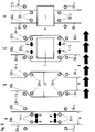
- FIG. 2 shows a device 1000 for the production of RFID transponders.
- a first antenna wire 200a is provided by a first supply roller 202a as a quasi-endless antenna wire and is conveyed in cycles via the deflection rollers 204 to a take-up roller 206 .
- a second antenna wire 200b is provided by a second supply roller 202b as a quasi-endless antenna wire and is conveyed in cycles via the deflection rollers 204 to a take-up roller 206.
- the cyclically conveyed antenna wires 200a, 200b are arranged parallel to one another and are conveyed parallel to one another by the deflection and receiving rollers. In other words, the antenna wires 200a, 200b are arranged geometrically parallel to one another and are each simultaneously conveyed in cycles from the supply rollers 202a, 202b to the take-up roller 206.
- the 2 schematically a convex sliding surface 102.
- the sliding surface 102 is coated with polytetrafluoroethylene in the example shown.
- the sliding surface 102 is the antenna wires 200a, 200b facing surface of a 2 only schematically indicated body below the conveying path of the antenna wires 200a, 200b.
- the antenna wires 200a, 200b arranged parallel to one another are conveyed in the conveying direction F by the supply, deflection and take-up rollers in each case temporally and geometrically parallel to one another over the sliding surface 102.
- the device shown has a document supply roller 104, the document deflection rollers 106 and a document take-up roller 108.
- the document supply roller 104, the document deflection rollers 106 and the document take-up roller 108 together convey a strip-shaped, quasi-endless silicone paper 100 in the conveying direction F over the sliding surface 102.
- the silicon paper is conveyed in cycles analogous to the conveyance of the antenna wires 200a, 200b. Furthermore, the strip-shaped, quasi-endless silicone paper is conveyed over the sliding surface 102 in the conveying direction F at the same speed as the antenna wires 200a, 200b, so that in the area of the sliding surface 102 there is no or almost no relative movement and/or relative speed between the antenna wires 200a, 200b and the strip-shaped silicone paper 100 occurs.
- the silicone paper 100 is conveyed by the base supply roller 104, the base deflection rollers 106 and the base take-up roller 108 with a material tension and in contact with the sliding surface 102.
- the convex sliding surface 102 lengthens a conveying path of the silicone paper 100 between the deflection rollers 106 and thus causes the material tension of the silicone paper 100 in cooperation with the base supply roller 104, the base deflection rollers 106 and the base take-up roller 108.
- the material tension of the silicone paper is essentially in Directed towards the conveying direction F.
- the material tension of the silicone paper 100 ensures, on the one hand, that the silicone paper 100 is always conveyed in contact with the sliding surface 102 and, on the other hand, prevents or at least makes it more difficult for the silicone paper 100 to slip or fold unintentionally during processing.
- the supply rollers 202a, 202b, the deflection rollers 204 and the common take-up roller 206 are arranged and designed to promote the antenna wires 200a, 200b, which are conveyed in parallel in cycles, in contact with the silicone paper 100 and with a material tension.
- the material tension of the antenna wires 200a, 200b is caused/effected by the interaction of the supply rollers 202a, 202b, the deflection rollers 204, the common take-up roller 206 and the convex/curved sliding surface 102 with the silicone paper 100 conveyed on the sliding surface 102.
- deflection rollers (pairs) 204 can be arranged along the conveying path of the antenna wires 200a, 200b between the supply rollers 202a, 202b and the take-up roller 206, whereby two deflection rollers (pairs) 204 can be assigned to the sliding surface 102 .
- the convex sliding surface 102 with the silicone paper conveyed on it lengthens a conveying path of the antenna wires 200a, 200b between the deflection rollers 106 and thus causes the material tension of the antenna wires 200a, 200b in cooperation with the supply rollers 202a, 202b, the deflection rollers 204 and the common take-up roller 206.
- the material tension of the antenna wires 200a, 200b is directed essentially in the direction of the conveying direction F.
- the material tension of the antenna wires 200a, 200b enables them to be aligned precisely and in a straight line for processing and counteracts an unintentional slipping of the antenna wires 200a, 200b during processing.
- An advantage of the convex sliding surface is that a material tension of the antenna wires 200a, 200b can be achieved over a longer distance and/or with a lower exerted tension force than would be possible with freely tensioned wires.
- the influence of gravity on the tensioned wires is reduced and a qualitative distribution of the material tension in the antenna wires is improved.
- undesired twisting or twisting of the antenna wires is prevented or at least made more difficult.
- the device 1000 shown also includes a flux dispenser 302, at least one placement device 304 with an integrated soldering device for arranging transponder chips, a connecting device 306 for making electrical contact with the antenna wires 200a and 200b conveyed in parallel, and an insulation device 308 for applying an insulation coating to the antenna wires 200a and 200b.
- the device 1000 also includes a laser cutting device 310, which is arranged and designed to cut through one of the antenna wires 200a, 200b with a laser, and a sealing device 312, which applies a protective seal to the transponder chip that was arranged between the antenna wires. to apply.
- An inspection device 314 uses optical and electronic sensors or readout devices to check whether the manufactured transponder arrangements meet predetermined quality requirements.
- the processing devices 306 to 310 are above the antenna wires 200a, 200b conveyed over the sliding surface 102 and the silicon paper 100 conveyed or above the sliding surface 102 arranged.
- the silicone paper 100 conveyed in parallel with the antenna wires 200a, 200b can thus prevent the sliding surface 102 from being soiled, for example by the insulating varnish emitted by the insulating device 308.
- the flux dispenser 302, the loading device 304 and the inspection device 314 are not arranged above the sliding surface 102.
- additional processing stations can be arranged above or in the area of the antenna wires that are conveyed in parallel in cycles. At least part of the processing stations can be arranged above the sliding surface and at least part of the processing stations can be arranged above the conveyed antenna wires, but away from the sliding surface.
- the transponder arrangements produced by the processing stations 302 to 314 are rolled onto the take-up roll 206 as a quasi-endless sequence of transponder arrangements.
- the transponder arrangements produced can also be separated in a further processing step by cutting through the antenna wires 200a, 200b, so that individual transponder arrangements, such as in 1c shown arise.
- 3 shows schematically the arrangement of a transponder chip 10 between the antenna wires 200a, 200b by the placement device 304. 3 shows the antenna wires conveyed parallel to each other in a top view and in a comparison to 2 90° rotated perspective.
- a first step (A) four spacer pins 304b are lowered from a rest position above the antenna wires 200a, 200b, which are conveyed in parallel in cycles, into the area between the antenna wires 200a, 200b.
- the spacer pins 304b are each arranged in pairs or arranged symmetrically to the antenna wires 200a, 200b.
- the four spacer pins 304b in the area between the antenna wires 200a, 200b together define the corner points of a rectangle, with the antenna wires 200a, 200b each running parallel to two sides of the rectangle.
- four support pins 304a are lowered from a rest position above the antenna wires 200a, 200b, which are conveyed in parallel in cycles, into the area outside of the interior space formed by the antenna wires 200a, 200b.
- the support pins 304a are also arranged in pairs in the example shown or arranged symmetrically to the antenna wires 200a, 200b. In other words, it can be described that the four support pins 304a together define the corner points of a rectangle, with the antenna wires 200a, 200b each running parallel to two sides of the rectangle.
- the spacer pins 304b are moved in a direction R and in a reverse direction R', respectively.
- the direction R and the opposite direction R' in a plan view of the parallel antenna wires 200a, 200b, each run orthogonally to the conveying direction F of the 2 shown device.
- the parallel antenna wires 200a, 200b are connected by the in 2 shown device conveyed parallel to each other at a distance D1.
- 3 shows that the placement device 304 increases the distance between the antenna wires 200a, 200b temporarily and locally up to a placement distance D2 in a second step (B) by moving the spacer pins 304b in a direction R and in an opposite direction R′.
- the support pins 304a have the effect here that the increase in the spacing of the antenna wires 200a, 200b from one another is essentially locally limited, so that the processing operations at other processing stations are not impaired.
- Step 3 shows 3 that the placement device 304 in a third step (C) arranges a transponder chip 10 between the antenna wires in the area of the temporarily increased placement distance D2.
- the arrangement of the transponder chip 10, which has recesses for receiving the antenna wires 200a, 200b on two opposite side surfaces facing the antenna wires 200a, 200b, can be done, for example, with a vacuum gripper (not shown) or another device for handling transponder chips.
- the spacer pins 304b are each moved back in the opposite direction to the direction in which they were moved to temporarily change the distance between the antenna wires, until in a fourth step (D) the antenna wires 200a, 200b are arranged in contact with the wells of the transponder chip.
- the pick-and-place device now raises the support pins 304a and the spacer pins 304b until they are again positioned in the rest position above the antenna wires 200a, 200b, which are conveyed in parallel in cycles, so that a conveying path along the conveying direction F for the parallel antenna wires 200a, 200b and those arranged between them Transponder chip 10 is released.
- the parallel antenna wires 200a, 200b and the transponder chip 10 arranged between them are then conveyed along the conveying direction F.
- the vacuum gripper can, for example, be part of a "pick & place” device that picks up the chip at a pick-up location, for example from a provided wafer, and places it between the antenna wires.
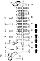
- transponder arrangement 4 shows schematically a step-by-step production of a transponder arrangement with a device 2 .
- transponder arrangements of different production stages can be located on the quasi-endlessly provided parallel antenna wires 200a, 200b.
- the transponder arrangements located in different production stages are each conveyed in cycles from one production station to another production station, with each production station carrying out at least one processing operation.
- a flux 30a, 30b is applied by the flux dispenser 302 to the antenna wires 200a, 200b, which are conveyed in parallel in cycles.
- a transponder chip 10 arranged between the mutually parallel antenna wires 200a, 200b. Furthermore, the transponder chip 10 is soldered to the antenna wires 200a, 200b, so that an electrically conductive connection is established between the antenna wires 200a, 200b and the contacts 18a, 18b of the transponder chip 10 (not in 4 shown, see 1 ) is made.
- a third step S3 the parallel antenna wires 200a, 200b are conveyed further in cycles along the conveying direction F until the antenna wires 200a, 200b and the transponder chip 10 soldered to them are arranged in contact with the silicone paper 100, which is conveyed in cycles and at the same conveying speed as the antenna wires 200a, 200b is conveyed over the sliding surface 102.
- a fourth step S4 the connecting device 306 produces an electrically conductive connection 201 between the antenna wires 200a, 200b conveyed in parallel.
- the insulation device 308 applies electrical insulation 32 or a dielectric to part of the conveyed antenna wires 200a, 200b and to part of the transponder chip 10.
- the silicone paper 100 prevents the applied insulation 32 from contaminating the slide base 102 .
- the insulation 32 is dried or cured by means of UV light.
- one of the conveyed antenna wires 200a and part of the applied insulation 34 is severed by a laser cutting device 310. This creates a recess/opening 34 in the insulation and in one of the antenna wires 200a. As a result, a transponder arrangement can be produced with antenna ends of different configurations.
- a seventh step S7 the parallel antenna wires 200a, 200b are further conveyed in cycles along the conveying direction F until the antenna wires 200a, 200b and the transponder chip 10 soldered to them are no longer arranged in contact with the silicone paper 100.
- the sealing device 312 applies a seal 36 to the transponder chip 10 and to part of the insulation 34.
- the seal 36 is also dried or cured by means of UV light.
- a ninth step S9 the functionality of the manufactured transponder arrangement is checked with an inspection device 314 .
- figure 5 shows a device 2000 for the production of RFID transponders.
- the device 200 has two supply rollers 202a, 202b, which each supply a quasi-endless antenna wire 200a, 200b.
- the provided quasi-endless antenna wires 200a, 200b are each laid by a laying device (not shown) with a laying arm (not shown) for each of the two provided antenna wires 200a, 200b between the in figure 5 shown wire feed units 402a, 402b clamped.
- the antenna wires 200a, 200b from the laying arms of the laying device are each U-shaped in a plan view (see also the following 7 and 8th ) and arranged under material tension around the antenna wire holders 404 arranged in pairs, so that overall there is a meandering arrangement of the antenna wires 200a, 200b on or between the wire feed units 402a, 402b.
- the antenna wire receivers 404 are L-shaped receiver hooks fastened to the wire conveyor units 402a, 402b, which in the specific example are configured as conveyor chains circulating in the conveying direction F (or clockwise).
- the antenna wire holders 404 protrude radially from the wire conveyor units 402a, 402b (or the circulating conveyor chains) and are arranged in pairs at regular intervals on the wire conveyor units 402a, 402b or the circulating conveyor chains in such a way that the provided antenna wires 200a, 200b parallel to each other span an interior space between the wire feed units 402a, 402b.
- the wire feed units 402a, 402b or the circulating conveyor chains feed the antenna wires 200a, 200b cyclically in the conveying direction F which are tensioned/stretched or arranged under a material tension in a U-shape around the antenna wire receivers 404 arranged in pairs.
- the antenna wires 200a, 200b that are tensioned or arranged under material tension are parallel to one another at least in sections and arranged/tensioned/tensioned at an angle to the conveying direction F, for example at an angle of approximately 90°.
- the wire conveyor units 402a, 402b or the circulating conveyor chains can have a distance from one another that can be changed automatically or manually. In this way, a length of the antenna wire sections arranged/tensioned/stretched at an angle to the conveying direction F can be set and/or adjusted and/or a material tension of the antenna wire sections can be increased or reduced.
- FIG figure 5 schematically shows a flux dispenser 302, an assembly device 304 with an integrated soldering device for arranging transponder chips, a connecting device 306 for making electrical contact with the conveyed antenna wires 200a and 200b, and an insulating device 308 for applying an insulating coating to the antenna wires 200a and 200b.
- the device 2000 also includes a laser cutting device 310, which is arranged and designed to cut through one of the antenna wires 200a, 200b with a laser, and a sealing device 312, which places a protective seal on the transponder chip that was arranged between the antenna wires. to apply.
- the functions of the individual processing stations are explained in more detail in connection with the following figures.
- the antenna wires 200a, 200b arranged under material tension on/on the wire feed units 402a, 402b have been conveyed in the conveying direction F past the last processing station provided (the sealing device 312 in the example shown)
- the antenna wires 200a, 200b with the finished transponder arrangements are shown in the Example of pickup device (not shown) detached from the wire feed units 402a, 402b and conveyed past an inspection device 314 via a deflection roller 204 to a common take-up roller 206.
- the pick-up device is optional and expressly not necessary in all embodiments.
- the wire feed units 402a, 402b and/or receivers 404 of the wire feed units 402a, 402b can be designed in such a way that they release the antenna wires 200a, 200b at a predetermined (feed) position.
- the inspection device 314 uses optical and electronic sensors or readout devices to check whether the manufactured transponder arrangements meet predetermined quality requirements.
- FIG figure 5 shows schematically the arrangement of a transponder chip 10 between the antenna wires 200a, 200b by the placement device 304. 6
- FIG figure 5 90° rotated perspective.
- a first step (A) four spacer pins 304b are lowered from a rest position above the parallel antenna wires 200a, 200b or parallel antenna wire sections conveyed in cycles into the area between the antenna wires 200a, 200b or parallel antenna wire sections.
- the spacer pins 304b are each arranged in pairs or arranged symmetrically to the antenna wires 200a, 200b.
- the four spacer pins 304b in the area between the antenna wires 200a, 200b together define the corner points of a rectangle, with the antenna wires 200a, 200b each running parallel to two sides of the rectangle.
- four support pins 304a are lowered from a rest position above the antenna wires 200a, 200b or parallel antenna wire sections conveyed cyclically in parallel into the area outside of the interior space formed by the antenna wires 200a, 200b.
- the support pins 304a are also arranged in pairs or arranged symmetrically to the antenna wires 200a, 200b. In other words, it can be described that the four support pins 304a together define the corner points of a rectangle, with the antenna wires 200a, 200b each running parallel to two sides of the rectangle.
- the spacer pins 304b are moved in a direction R and in a reverse direction R', respectively.
- the direction R and the opposite direction R′ here run parallel in a plan view Antenna wires 200a, 200b, each parallel to the conveying direction F of the in figure 5 shown device.
- the parallel antenna wires 200a, 200b or parallel antenna wire sections are connected from the 6 shown device conveyed parallel to each other at a distance D1.
- FIG. 12 further shows that the placement device 304 increases the distance between the antenna wires 200a, 200b temporarily and locally up to a placement distance D2 in a second step (B) by moving the spacer pins 304b in a direction R and in an opposite direction R′.
- the support pins 304a have the effect here that the increase in the distance between the antenna wires 200a, 200b is essentially limited locally, so that the antenna wires 200a, 200b do not become detached from the antenna wire holders 404 unintentionally.
- the placement device 304 in a third step (C) arranges a transponder chip 10 between the antenna wires 200a, 200b in the area of the temporarily increased placement distance D2.
- the arrangement of the transponder chip 10, which has recesses for receiving the antenna wires 200a, 200b on two opposite side surfaces facing the antenna wires 200a, 200b, can be done, for example, with a vacuum gripper (not shown) or another device for handling transponder chips.
- the spacer pins 304b are each moved back in the opposite direction to the direction in which they were moved to temporarily change the distance between the antenna wires, until in a fourth step (D) the antenna wires 200a, 200b are arranged in contact with the wells of the transponder chip.
- the pick-and-place device now raises the support pins 304a and the spacer pins 304b until they are again positioned in the rest position above the antenna wires 200a, 200b or above the antenna wire sections that are conveyed in parallel in cycles, so that a conveying path along the conveying direction F for the antenna wires 200a, 200b or , antenna wire sections and the transponder chip 10 arranged between them.
- the parallel antenna wires 200a, 200b and the transponder chip 10 arranged between them are then conveyed along the conveying direction F.
- transponder arrangement 7 shows schematically a step-by-step production of a transponder arrangement with a device figure 5 .
- transponder arrangements of different production stages can be located on the quasi-endlessly provided antenna wires 200a, 200b or on the mutually parallel antenna wire sections.
- the transponder arrangements, which are in different production stages, are each cycled by a production station conveyed to a further production station, each production station carrying out at least one machining process.
- a flux 30a, 30b is applied by the flux dispenser 302 to the antenna wires 200a, 200b that are conveyed in parallel in cycles or to the antenna wire sections that are conveyed in parallel.
- a transponder chip 10 is arranged between the mutually parallel antenna wires 200a, 200b or the mutually parallel antenna wire sections. Furthermore, the transponder chip 10 is soldered to the antenna wires 200a, 200b, so that an electrically conductive connection is established between the antenna wires 200a, 200b and the contacts 18a, 18b of the transponder chip 10 (not in 7 shown, see 1 ) is made.
- a fourth step S4 the connecting device 306 produces an electrically conductive connection 201 between the antenna wires 200a, 200b.
- the insulation device 308 applies electrical insulation 32 or a dielectric to part of the conveyed antenna wires 200a, 200b and to part of the transponder chip 10.
- the insulation 32 is dried or cured by means of UV light.
- one of the conveyed antenna wires 200a and part of the applied insulation 34 is severed by a laser cutting device 310. This creates a recess/opening 34 in the insulation and in one of the antenna wires 200a. As a result, a transponder arrangement can be produced with antenna ends of different configurations.
- the sealing device 312 applies a seal 36 to the transponder chip 10 and to part of the insulation 34.
- the seal 36 is also dried or cured by means of UV light.
- a ninth step S9 the functionality of the manufactured transponder arrangement is checked with an inspection device 314,
- FIG. 8 shows analogously the already in 7 Schematically illustrated production stages of a transponder arrangement. Deviating from that in the figure 5 and 7
- the manufacturing arrangement or manufacturing device 2000 shown has the 8 illustrated production arrangement
- the antenna wires 200a, 200b are in contact with the silicone paper 100 from production step S3 to production step S7.
- the silicone paper 100 which can be provided as strip-shaped, quasi-endless silicone paper 100, can be conveyed in the conveying direction F in the same way as the antenna wires 200a, 200b, so that the antenna wires 200a, 200b or the transponder arrangements in different stages of production have no or have at least approximately no relative movement/relative speed.
- the silicone paper 100 and/or the antenna wires 200a, 200b or the mutually parallel antenna wire sections can be conveyed over a sliding surface (not shown) that is convex in the conveying direction F and/or convex in a direction orthogonal to the conveying direction F.
- a flux 30a, 30b is applied by the flux dispenser 302 to the antenna wires 200a, 200b that are conveyed in parallel in cycles or to the antenna wire sections that are conveyed in parallel.
- a transponder chip 10 is arranged between the mutually parallel antenna wires 200a, 200b or the mutually parallel antenna wire sections. Furthermore, the transponder chip 10 is soldered to the antenna wires 200a, 200b, so that an electrically conductive connection is established between the antenna wires 200a, 200b and the contacts 18a, 18b of the transponder chip 10 (not in 8 shown, see 1 ) is made.
- a third step S3 the antenna wires 200a, 200b or mutually parallel antenna wire sections are further conveyed in cycles along the conveying direction F until the parallel antenna wire sections and the transponder chip 10 soldered to them are arranged in contact with the silicone paper 100, which can optionally be cyclically and with the same conveying speed as the antenna wires 200a, 200b is conveyed.
- a fourth step S4 the connecting device 306 produces an electrically conductive connection 201 between the antenna wires 200a, 200b.
- the insulation device 308 applies electrical insulation 32 or a dielectric to part of the conveyed antenna wires 200a, 200b and to part of the transponder chip 10.
- the insulation 32 is dried or cured by means of UV light.
- one of the conveyed antenna wires 200a and part of the applied insulation 34 is severed by a laser cutting device 310. This creates a recess/opening 34 in the insulation and in one of the antenna wires 200a. As a result, a transponder arrangement can be produced with antenna ends of different configurations.
- the sealing device 312 applies a seal 36 to the transponder chip 10 and to part of the insulation 34.
- the seal 36 is also dried or cured by means of UV light.
- a seventh step S7 the antenna wires 200a, 200b or mutually parallel antenna wire sections are further conveyed in cycles along the conveying direction F until the antenna wires 200a, 200b and the transponder chip 10 soldered to them are no longer arranged in contact with the silicone paper 100.
- a ninth step S9 the functionality of the manufactured transponder arrangement is checked with an inspection device 314 .
Description
Hier werden eine Vorrichtung und ein Verfahren zur Herstellung von elektronischen Vorrichtungen beschrieben. Insbesondere werden eine Vorrichtung und ein Verfahren zur Herstellung von RFID-Transpondern (= Radio Frequency Identification Transponder) beschrieben.Here, an apparatus and a method for manufacturing electronic devices are described. In particular, a device and a method for producing RFID transponders (=radio frequency identification transponder) are described.
Solche RFID-Transponder werden zum Beispiel für Etiketten, zum Beispiel Price-Tags, oder Wert- und Sicherheitsdokumente verwendet. Auch die Integration von RFID-Transpondern in Kleidungsstücke, Handtaschen, Uhren oder Gebrauchsgegenstände ist möglich, zum Beispiel um einen elektronisch auslesbaren Herkunfts- bzw. Echtheitsnachweis in diese Gegenstände zu integrieren.Such RFID transponders are used, for example, for labels, for example price tags, or value and security documents. The integration of RFID transponders in clothing, handbags, watches or everyday objects is also possible, for example to integrate an electronically readable proof of origin or authenticity into these objects.
Ein RFID-Transponder, hat im Wesentlichen einen Halbleiterchip und eine zum Beispiel als Schleifenantenne ausgestaltete RFID-Antenne. Die Antenne ermöglicht einen berührungslosen Datenzugriff, d.h. ein berührungsloses, automatisiertes Einschreiben bzw. Codieren und/oder Auslesen von (Personalisierungs- oder Herkunfts-)Daten in den/aus dem Halbleiterchip des Transponders.An RFID transponder essentially has a semiconductor chip and an RFID antenna designed, for example, as a loop antenna. The antenna enables contactless data access, i.e. contactless, automated writing or coding and/or reading of (personalization or origin) data in/from the semiconductor chip of the transponder.
Es sind bereits unterschiedliche Vorrichtungen zur Fertigung von RFID-Transpondern bekannt. Zum Beispiel sind Vorrichtungen bekannt, die Antennendrähte, welche zum Beispiel von Drahtspulen abgerollt werden, an verschiedenen Bearbeitungsstationen vorbeiführen. Während des Vorbeiführens werden die Antennendrähte in der Regel unter einer Materialspannung gehalten, da sich nur straff gespannte Drähte mit der erforderlichen Fertigungsgenauigkeit ausrichten lassen und nur solche straff gespannten Drähte während der Bearbeitung die erforderliche Positionsbeständigkeit aufweisen. Die Bearbeitungsstationen, zum Beispiel Bestückungs-, Löt,- oder Versiegelungsstationen fertigen hierbei sukzessive eine quasi-endlose Folge von RFID-Transpondern, welche durch ein anschließendes Durchtrennen der Antennendrähte voneinander getrennt und anschließend weiterverarbeitet werden können.Various devices for manufacturing RFID transponders are already known. Devices are known, for example, which guide antenna wires, which are unrolled from wire spools, for example, past various processing stations. During the passage, the antenna wires are generally kept under material tension, since only taut wires can be aligned with the required manufacturing accuracy and only such taut wires have the required positional stability during processing. The processing stations, for example assembly, soldering or sealing stations, successively produce a quasi-endless sequence of RFID transponders, which can be separated from one another by subsequently cutting through the antenna wires and then further processed.
Ein Nachteil hierbei ist jedoch, dass in der Regel eine Vielzahl von einzelnen Bearbeitungsstationen nötig ist, sodass die Antennendrähte - sollen diese nacheinander an den Bearbeitungsstationen nötig ist, sodass die Antennendrähte - sollen diese nacheinander an den Bearbeitungsstationen vorbeigeführt werden - üblicherweise über eine Distanz von mehreren Metern gespannt werden müssen. Gleichzeitig ist jedoch die maximale auf die Antennendrähte, welche naturgemäß einen beschränkten Durchmesser aufweisen, ausübbare Spannkraft begrenzt, da sonst die Antennendrähte während der Herstellung reißen würden. Somit ist die maximale Distanz, über die die Antennendrähte aufgespannt werden können ohne zu reißen und gleichzeitig die erforderliche Ausrichtungsgenauigkeit und Positionsbeständigkeit für eine Transponderfertigung aufweisen, begrenzt.A disadvantage here, however, is that a large number of individual processing stations is usually necessary, so that the antenna wires - these should be connected to the processing stations one after the other is necessary, so that the antenna wires - if they are to be routed past the processing stations one after the other - usually have to be stretched over a distance of several meters. At the same time, however, the maximum clamping force that can be exerted on the antenna wires, which naturally have a limited diameter, is limited, since otherwise the antenna wires would tear during production. Thus, the maximum distance over which the antenna wires can be stretched without tearing and at the same time having the required alignment accuracy and positional stability for transponder production is limited.
Da zudem jede Bearbeitungsstation eine bestimmte räumliche Breite bzw. Länge entlang der gespannten Drähte aufweist, ist die maximale Anzahl der Fertigungsstationen - und somit auch der Fertigungsschritte - durch die maximale auf die Antennendrähte der RFID-Transponder ausübbare Spannkraft begrenzt.Since each processing station also has a certain spatial width or length along the tensioned wires, the maximum number of production stations—and thus also the production steps—is limited by the maximum tension force that can be exerted on the antenna wires of the RFID transponder.
Vorrichtungen und Verfahren zur Fertigung von RFID-Transpondern mit zwei Antennendrähten, zwischen denen jeweils ein RFID-Chip angeordnet wird, werden zum Beispiel durch die Dokumente
Es besteht somit weiter Bedarf an einer verbesserten Vorrichtung und an einem verbesserten Verfahren zur Fertigung von RFID-Transpondern, welche insbesondere die Anordnung einer Vielzahl von einzelnen Bearbeitungsstationen entlang eines Förderweges ermöglichen.There is therefore still a need for an improved device and an improved method for manufacturing RFID transponders, which in particular enable the arrangement of a large number of individual processing stations along a conveying path.
Das technische Problem wird jeweils durch die Gegenstände der unabhängigen Ansprüche gelöst. Vorteilhafte Ausgestaltungen sind durch die abhängigen Ansprüche definiert.The technical problem is solved by the subject matter of the independent claims, respectively. Advantageous configurations are defined by the dependent claims.
Nach einem ersten Aspekt werden eine Vorrichtung und ein Verfahren mit einer Gleitfläche vorgeschlagen.According to a first aspect, a device and a method with a sliding surface are proposed.
Eine Vorrichtung zur Herstellung von RFID-Transpondern weist zumindest eine Gleitfläche und eine Drahtfördervorrichtung auf, die dazu angeordnet und ausgebildet ist, zumindest zwei Antennendrähte in einer Förderrichtung zu fördern, wobei die Antennendrähte hierbei zumindest abschnittsweise zueinander parallel angeordnet sind. Zumindest eine Bestückungsvorrichtung ist dazu angeordnet und ausgebildet, einen Transponderchip zwischen den parallel angeordneten Antennendrähten anzuordnen bzw. zu platzieren.A device for producing RFID transponders has at least one sliding surface and a wire feed device which is arranged and designed to feed at least two antenna wires in one feed direction, with the antenna wires being arranged parallel to one another at least in sections. At least one placement device is arranged and designed to arrange or place a transponder chip between the antenna wires arranged in parallel.
Insbesondere kann die Bestückungsvorrichtung dazu angeordnet und ausgebildet sein, einen Transponderchip zwischen den parallel angeordneten Antennendrähten derart anzuordnen/zu positionieren, dass eine elektrisch leitende Verbindung zwischen den Antennendrähten und dem Transponderchip, insbesondere mit Anschlusskontakten des Transponderchips, hergestellt wird.In particular, the equipping device can be arranged and designed to arrange/position a transponder chip between the antenna wires arranged in parallel in such a way that an electrically conductive connection between the antenna wires and the transponder chip, in particular with connection contacts of the transponder chip.
Die Drahtfördervorrichtung ist ferner dazu angeordnet und ausgebildet, die Antennendrähte zumindest abschnittsweise über die Gleitfläche hinweg zu fördern und die Antennendrähte im Zusammenwirken mit der Gleitfläche zu spannen, sodass die Antennendrähte eine Materialspannung längs der Förderrichtung aufweisen.The wire feed device is also arranged and designed to feed the antenna wires at least in sections over the sliding surface and to tension the antenna wires in cooperation with the sliding surface, so that the antenna wires have a material tension along the conveying direction.
Ein Spannen eines Antennendrahtes im Sinne der Erfindung bezeichnet hierbei das Ausüben einer Kraft und/oder das Hervorrufen bzw. Bewirken einer Materialspannung längs der Längenrichtung bzw. Dochtlinie eines Antennendrahtes. Mit anderen Worten ist ein Antennendraht dann gespannt, wenn eine Kraft parallel zu seiner Längenausdehnung wirkt, sodass eine Materialspannung in dem Antennendraht besteht, welche zumindest nicht vollständig durch eine Deformation des Antennendrahts ausgeglichen werden kann, und der Antennendraht in der Richtung der wirkenden Kraft ausgerichtet ist.Tensioning of an antenna wire within the meaning of the invention refers to the exertion of a force and/or the evocation or effecting of a material tension along the length direction or wick line of an antenna wire. In other words, an antenna wire is taut when a force acts parallel to its length extension, so that there is a material stress in the antenna wire that cannot be completely compensated for by deformation of the antenna wire, and the antenna wire is aligned in the direction of the acting force .
Ein Vorteil dieser Vorrichtung ist es, das die Distanz, über die ein Antennendraht gespannt und an verschiedenen Bearbeitungsstationen vorbei gefördert werden kann, gegenüber bekannten Vorrichtungen vergrößert ist, ohne das hierzu eine von einer Drahtfördervorrichtung auf den Antennendraht ausgeübte Spannkraft erhöht werden müsste. Die Gleitfläche, über die der Antennendraht gefördert wird, ermöglicht es, die Antennendrähte über eine vergrößerte Distanz straff gespannt zu halten und/oder zu fördern, ohne dass hierbei auf einen einzelnen Abschnitt der Antennendrähte eine Kraft wirkt, die dessen Zerstörung bewirken würde.An advantage of this device is that the distance over which an antenna wire can be tensioned and conveyed past various processing stations is increased compared to known devices without the tension force exerted on the antenna wire by a wire conveying device having to be increased. The sliding surface over which the antenna wire is conveyed makes it possible to keep the antenna wires taut over an increased distance and/or to convey them without a force acting on an individual section of the antenna wire that would cause its destruction.
Die Gleitfläche kann zumindest teilweise konvex geformt sein, wobei die konvexe Krümmung zumindest im Wesentlichen in Richtung der Förderrichtung ausgeformt ist. Zumindest ein der den Antennendrähten zugewandter Teil der Gleitfläche kann mit einer Beschichtung, zum Beispiel mit einer Polytetrafluorethylenbeschichtung, ausgebildet sein.The sliding surface can be at least partially convex in shape, with the convex curvature being formed at least essentially in the direction of the conveying direction. At least one part of the sliding surface facing the antenna wires can be provided with a coating, for example with a polytetrafluoroethylene coating.
Ferner kann die Vorrichtung zumindest eine Unterlagenfördervorrichtung aufweisen, die dazu angeordnet und ausgebildet ist, eine Verarbeitungsunterlage, insbesondere ein Silikonpapier, in der Förderrichtung über die Gleitfläche zu fördern.Furthermore, the device can have at least one substrate conveying device, which is arranged and designed to convey a processing substrate, in particular silicone paper, in the conveying direction over the sliding surface.
Ein Vorteil hierbei ist, dass die Antennendrähte nicht unmittelbar in Anlage mit der Gleitfläche sondern auf der Verarbeitungsunterlage gefördert werden können. Hierdurch wird zum Beispiel eine Verschmutzung der Gleitfläche während der Fertigung der RFID-Transponder vermieden.An advantage here is that the antenna wires cannot be conveyed directly in contact with the sliding surface but on the processing base. This avoids, for example, contamination of the sliding surface during production of the RFID transponder.
Die Unterlagenfördervorrichtung kann ferner dazu angeordnet und ausgebildet sein, die Verarbeitungsunterlage im Zusammenwirken mit der Gleitfläche zu spannen.The base conveyor device can also be arranged and configured to tension the processing base in cooperation with the sliding surface.
Ein Spannen der Verarbeitungsunterlage im Sinne der Erfindung bezeichnet hierbei das Ausüben einer Kraft und/oder das Hervorrufen bzw. Bewirken einer Materialspannung längs der Längenrichtung einer insbesondere streifenförmigen Verarbeitungsunterlage, welche insbesondere ein Silikonpapier sein kann. Mit anderen Worten ist eine Verarbeitungsunterlage dann gespannt, wenn eine Kraft parallel zu ihrer Längenausdehnung wirkt, sodass eine Materialspannung in der Verarbeitungsunterlage besteht, welche zumindest nicht vollständig durch eine Deformation der Verarbeitungsunterlage ausgeglichen werden kann, und die Verarbeitungsunterlage in der Richtung der wirkenden Kraft ausgerichtet ist.Tensioning of the processing base in the context of the invention refers to exerting a force and/or causing or effecting a material tension along the length direction of a particularly strip-shaped processing base, which can be silicone paper in particular. In other words, a processing base is taut when a force acts parallel to its length extension, so that there is a material stress in the processing base that cannot be completely compensated for by deformation of the processing base, and the processing base is aligned in the direction of the acting force .
Weiter kann die Unterlagenfördervorrichtung die Verarbeitungsunterlage in derselben Fördergeschwindigkeit fördern, in der die Drahtfördervorrichtung die Antennendrähte fördert, sodass zwischen der Verarbeitungsunterlage und den Antennendrähten keine Relativbewegung und/oder Relativgeschwindigkeit auftritt.Furthermore, the base conveying device can convey the processing base at the same conveying speed at which the wire conveying device conveys the antenna wires, so that no relative movement and/or relative speed occurs between the processing base and the antenna wires.
Ein Vorteil hierbei ist, dass keine oder nur wenig Reibung zwischen den Antennendrähten und der Verarbeitungsunterlage auftritt, sodass einem ungewollten/unbeabsichtigten Verschieben und/oder einer ungewollten/ unbeabsichtigten Positionsveränderung der Antennendrähte aufgrund einer Reibung der Antennendrähte auf der Gleitunterlage entgegengewirkt werden kann.One advantage here is that there is little or no friction between the antenna wires and the processing base, so that unwanted/unintentional displacement and/or an unwanted/unintentional change in position of the antenna wires due to friction of the antenna wires on the sliding base can be counteracted.
Die Unterlagenfördervorrichtung kann die Verarbeitungsunterlage taktweise fördern. Ebenso kann die Drahtfördervorrichtung die Antennendrähte taktweise fördern. Ein Vorteil hierbei ist, dass die Antennendrähte und/oder die Verarbeitungsunterlage während einer Fertigung bzw. Bearbeitung durch eine Fertigungsstation, zum Beispiel während der Anordnung eines Transponderchips durch eine Bestückungsvorrichtung, in einer Ruhelage sind. Mit anderen Worten ermöglicht ein taktweises Fördern der Antennendrähte und/oder der Verarbeitungsunterlage, dass die Antennendrähte und/oder die Verarbeitungsunterlage während einer Fertigung bzw. Bearbeitung durch eine Fertigungsstation keine Relativbewegung und/oder Relativgeschwindigkeit in der Förderrichtung zu der jeweiligen Fertigungsstation aufweisen.The sheet conveying device can convey the processing sheet in a cyclic manner. Likewise, the wire feed device can promote the antenna wires in cycles. One advantage here is that the antenna wires and/or the processing base are in a rest position during production or processing by a production station, for example during the arrangement of a transponder chip by an assembly device. In other words, cyclic conveying of the antenna wires and/or the processing base makes it possible for the antenna wires and/or the processing base to have no relative movement and/or relative speed in the conveying direction to the respective production station during production or processing by a production station.
Die Unterlagenfördervorrichtung kann zudem dazu angeordnet und ausgebildet sein, die Verarbeitungsunterlage in Anlage mit der Gleitfläche anzuordnen und die Verarbeitungsunterlage mit einer Gleitreibung über die Gleitfläche zu fördern.The base conveying device can also be arranged and configured to arrange the processing base in contact with the sliding surface and to convey the processing base over the sliding surface with sliding friction.
Die Drahtfördervorrichtung kann dazu angeordnet und ausgebildet sein, die Antennendrähte zumindest abschnittsweise in Anlage mit der Gleitfläche anzuordnen und die Antennendrähte mit einer Gleitreibung über die Gleitfläche zu fördern.The wire conveying device can be arranged and designed to arrange the antenna wires in contact with the sliding surface at least in sections and to convey the antenna wires over the sliding surface with sliding friction.
Alternativ kann die Drahtfördervorrichtung dazu ausgebildet und angeordnet sein, die Antennendrähte zumindest abschnittsweise in Anlage mit der Verarbeitungsunterlage anzuordnen.Alternatively, the wire feed device can be designed and arranged to arrange the antenna wires at least in sections in contact with the processing base.
In einer Variante kann die Drahtfördervorrichtung eine oder mehrere Bereitstellungsrollen und/oder eine oder mehrere Umlenkrollen und/oder eine Aufnahmerolle aufweisen.In one variant, the wire feed device can have one or more supply rollers and/or one or more deflection rollers and/or a take-up roller.
Ferner kann die Unterlagenfördervorrichtung eine Unterlagenbereitstellungsrolle und/oder eine oder mehrere Umlenkrollen und/oder eine Unterlagenaufnahmerolle aufweisen.Furthermore, the document conveyor device can have a document supply roller and/or one or more deflection rollers and/or a document receiving roller.
Ein Vorteil hierbei ist, dass die Antennendrähte und/oder die Gleitunterlage jeweils als quasi-endlose Fertigungsmaterialien bereitgestellt werden können, sodass die Effizienz einer Fertigung von großen Stückzahlen von RFID-Transpondern befördert wird.One advantage here is that the antenna wires and/or the sliding base can each be provided as quasi-endless production materials, so that the efficiency of production of large numbers of RFID transponders is promoted.
Die Gleitfläche kann sich über mindestens 25%, insbesondere über mindestens 50%, des Förderweges der Antennendrähte ausdehnen, sodass die Antennendrähte über mindestens 25%, insbesondere über mindestens 50%, des gesamten Förderweges - von der/den Bereitstellungsrolle/n bis hin zur Aufnahmerolle - in Anlage mit der Gleitfläche oder in Anlage mit einer über die Gleitfläche geförderten Verarbeitungsunterlage angeordnet sind.The sliding surface can extend over at least 25%, in particular over at least 50%, of the conveying path of the antenna wires, so that the antenna wires over at least 25%, in particular over at least 50%, of the entire conveying path - from the supply roll(s) to the take-up roll - are arranged in contact with the sliding surface or in contact with a processing substrate conveyed over the sliding surface.
In einer Variante kann die Bestückungsvorrichtung dazu angeordnet und ausgebildet sein, einen Abstand der zumindest abschnittsweise zueinander parallelen Antennendrähte temporär lokal zu verändern, sodass die Antennendrähte im Bereich der Bestückungsvorrichtung temporär einen Bestückungsabstand zueinander aufweisen, der größer ist als der Abstand der Antennendrähte außerhalb des Bereichs der Bestückungsvorrichtung. Hierdurch können insbesondere in einem Querschnitt T-förmige Transponderchips und/oder Transponderchips mit einer seitlichen Vertiefung zur Aufnahme von Antennendrähten zwischen den parallelen Antennendrähten angeordnet werden.In one variant, the placement device can be arranged and configured to temporarily locally change a distance between the antenna wires that are parallel to one another at least in sections, so that the antenna wires in the area of the placement device temporarily have a placement distance from one another that is greater than the distance between the antenna wires outside the area of the placement device. In this way, transponder chips with a T-shaped cross section and/or transponder chips with a lateral depression for receiving antenna wires can be arranged between the parallel antenna wires.
Mit anderen Worten ist die Bestückungsvorrichtung dazu angeordnet und ausgebildet, den Abstand zwischen den zumindest zwei Antennendrähten in einem vorbestimmten Bereich bzw. Drahtabschnitt vorübergehend zu vergrößern, sodass das Anordnen eines Transponderchips zwischen den Antennendrähten ermöglicht oder zumindest erleichtert wird. Anschlie-βend, nach dem Positionieren des Transponderchips in einem von den Antennendrähten umgebenen Zwischenraum, kann die Bestückungsvorrichtung den Abstand zwischen den Antennendrähten wieder auf den ursprünglichen Abstand reduzieren, sodass die Antennendrähte vorzugsweise jeweils in Anlage mit dem zwischen ihnen positionierten Transponderchip angeordnet sind.In other words, the equipping device is arranged and designed to temporarily increase the distance between the at least two antenna wires in a predetermined area or wire section, so that the arrangement of a transponder chip between the antenna wires is made possible or at least facilitated. Then-βend, after positioning the transponder chip in a space surrounded by the antenna wires, the pick-and-place device can measure the distance between the Reduce antenna wires back to the original distance, so that the antenna wires are preferably each arranged in contact with the transponder chip positioned between them.
Weiter kann die Bestückungsvorrichtung ein oder mehrere Abstandsveränderungselement/e, insbesondere Abstandsstifte, aufweisen, die jeweils in einer Richtung und in einer der Richtung entgegengesetzten Gegenrichtung beweglich sind, wobei die Richtung und die Gegenrichtung jeweils winklig, insbesondere orthogonal, zur Förderrichtung und orthogonal zur Flächennormalen einer durch die zumindest abschnittsweise zueinander parallelen Antennendrähte verlaufenden Ebene verlaufen.Furthermore, the pick-and-place device can have one or more distance-changing elements, in particular spacer pins, which can each be moved in one direction and in a direction opposite to the direction, with the direction and the opposite direction each being at an angle, in particular orthogonal, to the conveying direction and orthogonal to the surface normal run through the plane running parallel to one another at least in sections.
Ferner können die Abstandsveränderungselemente parallel zu einer Flächennormalen einer durch die zumindest abschnittsweise zueinander parallelen Antennendrähte verlaufenden Ebene absenkbar und anhebbar sein, wobei die Abstandsveränderungselemente in einem abgesenkten Zustand zwischen den Antennendrähten angeordnet sind und in einem angehobenen Zustand nicht zwischen den geförderten Antennendrähten angeordnet sind.Furthermore, the distance-changing elements can be lowered and raised parallel to a surface normal of a plane running through the antenna wires that are parallel to one another at least in sections, with the distance-changing elements being arranged between the antenna wires in a lowered state and not being arranged between the conveyed antenna wires in a raised state.
Mit anderen Worten kann die Bestückungsvorrichtung Abstandsstifte, insbesondere Paare von Abstandsstiften aufweisen, die aus einer Ruheposition in einen Bereich zwischen die Antennendrähte hinein abgesenkt werden können und anschließend durch eine Bewegung winklig zur Förderrichtung der Drähte in Anlage mit den Drähten gebracht werden können. Weiter können die Abstandsstifte durch eine weitere Bewegung winklig zur Förderrichtung die Position der Antennendrähte, welche sich nun in Anlage mit den Abstandsstiften befinden, so verändern, dass sich ein Abstand der Antennendrähte zueinander, zumindest in einem Bereich der Abstandsstifte, erhöht. Hierbei kann sich die Materialspannung der Antennendrähte ebenfalls temporär erhöhen. Nachdem der Transponderchip durch die Bestückungsvorrichtung zwischen den Antennendrähten positioniert/angeordnet ist, können sich die Abstandsstifte entgegen der Bewegung zur Vergrößerung des Abstands zurückbewegen, sodass sich der Abstand der Antennendrähte wieder verringert. Sobald sich die Abstandsstifte wieder zwischen den Antennendrähten befinden und/oder sich nicht weiter in Anlage mit den Antennendrähten befinden, können die Abstandsstifte wieder in die Ruheposition hinein angehoben werden bzw. aus dem Bereich zwischen den Antennendrähten entfernt werden, sodass ein Förderweg in der Förderrichtung für die Antennendrähte und den zwischen ihnen angeordneten Transponderchip freigegeben bzw. nicht behindert ist.In other words, the placement device can have spacer pins, in particular pairs of spacer pins, which can be lowered from a rest position into an area between the antenna wires and then brought into contact with the wires by a movement at an angle to the conveying direction of the wires. Furthermore, the spacer pins can change the position of the antenna wires, which are now in contact with the spacer pins, by a further movement at an angle to the conveying direction, such that the distance between the antenna wires increases, at least in one area of the spacer pins. The material tension of the antenna wires can also increase temporarily. After the transponder chip has been positioned/arranged between the antenna wires by the placement device, the spacer pins can move back against the movement to increase the distance, so that the distance between the antenna wires is reduced again. As soon as the spacer pins are again between the antenna wires and/or are no longer in contact with the antenna wires, the spacer pins can be raised back into the rest position or removed from the area between the antenna wires, so that a conveying path in the conveying direction for the antenna wires and the transponder chip arranged between them is released or not obstructed.
In einer Variante kann die Bestückungsvorrichtung weiter, alternativ oder ergänzend zu den Abstandsstiften, in einem Querschnitt dreieckförmige, zumindest abschnittsweise elliptische oder zumindest abschnittsweise trapezförmige Abstandsveränderungselemente in einen Bereich zwischen den zumindest abschnittsweise zueinander parallel angeordneten Antennendrähte einbringen, wobei die in einem Querschnitt dreieckförmigen, zumindest abschnittsweise elliptischen oder zumindest abschnittsweise trapezförmigen Abstandsveränderungselemente bereits durch das Absenken in den Bereich zwischen die Antennendrähte zunächst in Anlage mit diesen gelangen und durch ein weiteres Absenken einen Abstand der Antennendrähte zueinander temporär lokal vergrößern. Ein Anheben der in einem Querschnitt dreieckförmigen, zumindest abschnittsweise elliptischen oder zumindest abschnittsweise trapezförmigen Abstandsveränderungselemente beendet die temporäre Vergrößerung des Abstands der Antennendrähte.In one variant, the placement device can further, alternatively or in addition to the spacer pins, in a cross-section, triangular, at least partially elliptical or at least partially trapezoidal distance changing elements in a Introduce an area between the antenna wires arranged parallel to one another at least in sections, with the distance changing elements, which are triangular in cross section, at least partially elliptical or at least partially trapezoidal in shape, already come into contact with the antenna wires by being lowered into the area between them and by further lowering a distance of the Temporarily increase the size of the antenna wires locally. Raising the distance changing elements, which are triangular in cross section, elliptical at least in sections, or trapezoidal in sections at least, ends the temporary increase in the distance between the antenna wires.
Der Fachmann versteht hierbei, dass die Anzahl der Abstandsveränderungselemente im Grundsatz frei gewählt werden kann und dass bereits ein einziges Abstandsveränderungselement im Grundsatz ausreichend ist, um einen Abstand der Antennendrähte zueinander temporär zu verändern. Ferner versteht der Fachmann, dass ein Absenken und ein Anheben im Sinne der Erfindung zwei zueinander entgegengesetzte Bewegungsrichtungen bezeichnen, jedoch keine Position der Bestückungsvorrichtung oder Teile der Bestückungsvorrichtung in Relation zu den geförderten Antennendrähten festlegen. Insbesondere kann sich eine Ruhelage der Abstandsveränderungselemente sowohl oberhalb als auch unterhalb der geförderten Antennendrähte befinden, sodass ein Absenken stets eine Bewegung der Abstandsveränderungselemente in den Bereich zwischen den Antennendrähten hinein bezeichnet und ein Anheben stets eine Bewegung aus dem Bereich zwischen den Antennendrähten heraus bezeichnet.The person skilled in the art understands that the number of distance-changing elements can in principle be freely selected and that a single distance-changing element is in principle sufficient to temporarily change the distance between the antenna wires. Furthermore, the person skilled in the art understands that lowering and raising in the sense of the invention denote two opposite directions of movement, but do not define a position of the placement device or parts of the placement device in relation to the conveyed antenna wires. In particular, a rest position of the distance-changing elements can be both above and below the conveyed antenna wires, so that a lowering always denotes a movement of the distance-changing elements into the area between the antenna wires and raising always denotes a movement out of the area between the antenna wires.
In einer Weiterbildung kann die Bestückungsvorrichtung ferner Unterstützungselemente, insbesondere Unterstützungsstifte, aufweisen, die dazu angeordnet und ausgebildet sind, einen temporär lokal vergrößerten Abstand der Antennendrähte räumlich zumindest teilweise zu begrenzen. Insbesondere können die Unterstützungselemente jeweils an einer dem Bereich zwischen den Antennendrähten abgewandten (Außen-)Seite der Antennendrähte angeordnet sein. Ferner können die Unterstützungselemente von den jeweiligen Antennendrähten zumindest soweit beabstandet sein, dass ein Förderweg in der Förderrichtung für die Antennendrähte und den zwischen ihnen angeordneten Transponderchip freigegeben bzw. nicht behindert ist. In einer Weiterbildung können die Unterstützungselemente zudem in einer Richtung in einem Winkel zur Förderrichtung und in einer hierzu korrespondierenden Gegenrichtung beweglich sein. Zudem können auch die Unterstützungselemente absenkbar und/oder anhebbar sein, zum Beispiel um einen Förderweg freizugeben.In a development, the equipping device can also have support elements, in particular support pins, which are arranged and designed to spatially at least partially limit a temporarily locally increased spacing of the antenna wires. In particular, the support elements can each be arranged on an (outside) side of the antenna wires that faces away from the region between the antenna wires. Furthermore, the support elements can be spaced at least far enough from the respective antenna wires that a conveying path in the conveying direction for the antenna wires and the transponder chip arranged between them is released or not obstructed. In a further development, the support elements can also be movable in a direction at an angle to the conveying direction and in an opposite direction corresponding thereto. In addition, the support elements can also be lowered and/or raised, for example in order to release a conveying path.
Ein Vorteil hierbei ist, dass eine Beeinträchtigung weiterer Bearbeitungsstationen bzw. Bearbeitungsschritte durch den von der Bestückungsvorrichtung temporär veränderten Abstand der Antennendrähte reduziert werden kann.One advantage here is that impairment of further processing stations or processing steps as a result of the distance between the antenna wires being temporarily changed by the placement device can be reduced.
Weiter kann die Vorrichtung zur Herstellung von RFID-Transpondern einen Flussmittelspender aufweisen der dazu angeordnet und ausgebildet ist, jeweils einen Flussmittelauftrag, der ein Verlöten der Antennendrähte mit einem Transponderchip erleichtert, auf die Antennendrähte aufzutragen.Furthermore, the device for producing RFID transponders can have a flux dispenser which is arranged and designed to apply a flux application to the antenna wires in each case, which facilitates soldering of the antenna wires to a transponder chip.
Ferner kann eine Lötvorrichtung, dazu angeordnet und ausgebildet sein, jeweils ein Lot auf die zumindest abschnittsweise zueinander parallelen Antennendrähte und/oder auf einen Transponderchip bzw. auf einen Teil eines Transponderchips aufzubringen und die zumindest abschnittsweise zueinander parallelen Antennendrähte mit einem zwischen ihnen angeordneten Transponderchip zu verlöten; insbesondere kann die Lötvorrichtung gemeinsam bzw. als gemeinsame Baugruppe mit der Bestückungsvorrichtung ausgebildet sein.Furthermore, a soldering device can be arranged and designed to apply solder to the antenna wires that are parallel to one another at least in sections and/or to a transponder chip or to part of a transponder chip and to solder the antenna wires that are parallel to one another at least in sections to a transponder chip arranged between them ; In particular, the soldering device can be designed jointly or as a joint assembly with the equipping device.
Eine Verbindungsvorrichtung kann dazu angeordnet und ausgebildet sein, eine elektrisch leitende Verbindung zwischen den Antennendrähten herzustellen. Hierzu kann zum Beispiel eine elektrisch leitende Verbindung durch einen elektrisch leitenden Materialauftrag, welcher zum Beispiel eine Silberverbindung oder eine silberhaltige Verbindungssubstanz sein kann, zwischen den zumindest abschnittsweise zueinander parallelen Antennendrähten hergestellt werden. Optional kann die Verbindungsvorrichtung weiter eine Vorrichtung zur Trocknung/Antrocknung eines aufgebrachten Materialauftrags aufweisen, zum Beispiel eine Heißlufttrocknungsvorrichtung. Alternativ können die Antennendrähte zum Beispiel auch miteinander verlötet werden oder es kann ein elektrisch leitendes Verbindungselement zwischen die Antennendrähte angeordnet und mit diesen elektrisch leitend verbunden, insbesondere verlötet werden.A connecting device can be arranged and designed to produce an electrically conductive connection between the antenna wires. For this purpose, for example, an electrically conductive connection can be produced by an electrically conductive material application, which can be a silver compound or a silver-containing connecting substance, for example, between the antenna wires that are parallel to one another at least in sections. Optionally, the connecting device can also have a device for drying/pre-drying an applied material application, for example a hot-air drying device. Alternatively, the antenna wires can also be soldered to one another, for example, or an electrically conductive connecting element can be arranged between the antenna wires and connected to them in an electrically conductive manner, in particular soldered.
Weiter kann eine Isolationsvorrichtung dazu angeordnet und ausgebildet sein, zumindest einen Teil der Antennendrähte und/oder zumindest einen Teil der elektrisch leitenden Verbindung mit einem Isolationsmaterial zu umgeben. Dieses kann zum Beispiel durch einen dielektrischen Materialauftrag, insbesondere durch eine Isolationslackierung, geschehen. In einer Weiterbildung kann die Isolationsvorrichtung zudem eine UV-Bestrahlungsvorrichtung umfassen, die dazu angeordnet ist, einen durch die Isolationsvorrichtung aufgebrachten Materialauftrag, insbesondere eine Isolationslackierung, mittels UV-Licht anzutrocknen und/oder auszuhärten.Furthermore, an insulation device can be arranged and designed to surround at least part of the antenna wires and/or at least part of the electrically conductive connection with an insulation material. This can be done, for example, by applying a dielectric material, in particular by insulating paint. In one development, the insulation device can also include a UV irradiation device, which is arranged to dry and/or harden a material application applied by the insulation device, in particular an insulation coating, by means of UV light.
Eine Trennvorrichtung, insbesondere eine Laser-Trennvorrichtung kann dazu angeordnet und ausgebildet sein, zumindest einen der Antennendrähte und/oder zumindest einen Teil des Isolationsmaterials zu durchtrennen/perforieren/unterbrechen. Hierdurch kann eine Länge einer Antenne einer zu fertigenden Transponderanordnung eingestellt bzw. hergestellt werden. Insbesondere können offene bzw. nicht zu einer Schleife geformte Enden einer Antenne gleichlang oder unterschiedlich lang hergestellt werden.A cutting device, in particular a laser cutting device, can be arranged and designed to cut through/perforate/interrupt at least one of the antenna wires and/or at least part of the insulation material. In this way, the length of an antenna of a transponder arrangement to be manufactured can be set or produced. In particular, the ends of an antenna that are open or not formed into a loop can be produced with the same length or with different lengths.
Zusätzlich kann eine Versiegelungsvorrichtung dazu angeordnet und ausgebildet sein, eine Versiegelung zumindest auf einen Teil des Transponderchips und/oder auf das Isolationsmaterial und/oder auf die Antennendrähte aufzutragen. Die Versiegelung kann insbesondere ein mittels UV-Licht aushärtbarer Materialauftrag sein. Hierzu kann auch die Versiegelungsvorrichtung eine UV-Bestrahlungsvorrichtung umfassen, die dazu angeordnet und ausgebildet ist, einen durch die Versiegelungsvorrichtung aufgebrachten Materialauftrag mittels UV-Licht anzutrocknen und/oder auszuhärten.In addition, a sealing device can be arranged and designed to apply a seal to at least part of the transponder chip and/or to the insulating material and/or to the antenna wires. The seal can in particular be a material application that can be cured by means of UV light. For this purpose, the sealing device can also comprise a UV irradiation device, which is arranged and designed to dry and/or harden a material application applied by the sealing device by means of UV light.
Weiter kann die Vorrichtung zur Herstellung von RFID-Transpondern eine Inspektionsvorrichtung umfassen, die dazu angeordnet und ausgebildet ist, Eigenschafts- und/oder Positionierungsfehler eines Transponderchips und/oder einer Transponderanordnung zu ermitteln. Eine Transponderanordnung bezeichnet hierbei eine Anordnung umfassend einen Transponderchip und zumindest jeweils einen Abschnitt von zumindest zwei Antennendrähten und/oder eine Verbindung und/oder ein Isolationsmaterial und/oder eine Versiegelung. Die Inspektionsvorrichtung kann zum Beispiel optisch erfassende Sensoren, insbesondere eine Kameraanordnung, aufweisen, die dazu geeignet ist Lage- bzw. Positionierungsfehler einer Transponderanordnung und/oder eines Teils der Transponderanordnung zu ermitteln und/oder optisch erkennbare Eigenschaftsfehler der Transponderanordnung und/oder eines Teils der Transponderanordnung zu ermitteln. In einer Weiterbildung kann die Inspektionsvorrichtung auch eine Vorrichtung zum Auslesen von RFID-Transpondern umfassen, die dazu angeordnet und ausgebildet ist, eine Transponderanordnung/einen RFID-Transponder auf Funktionsfähigkeit zu überprüfen. Ferner kann die Inspektionsvorrichtung eine Schreibvorrichtung aufweisen, die dazu angeordnet und ausgebildet ist, eine Transponderanordnung/einen RFID-Transponder zu Codieren bzw. Daten an eine Transponderanordnung/einen RFID-Transponder zu übertragen. Optional kann die Schreibvorrichtung gemeinsam mit der Vorrichtung zum Codieren und/oder Auslesen von RFID-Transpondern ausgebildet sein.Furthermore, the device for producing RFID transponders can comprise an inspection device which is arranged and designed to determine property and/or positioning errors of a transponder chip and/or a transponder arrangement. In this case, a transponder arrangement designates an arrangement comprising a transponder chip and at least one section of at least two antenna wires and/or a connection and/or an insulating material and/or a seal. The inspection device can, for example, have optically detecting sensors, in particular a camera arrangement, which is suitable for determining location or positioning errors in a transponder arrangement and/or part of the transponder arrangement and/or optically recognizable property errors in the transponder arrangement and/or part of the transponder arrangement to investigate. In one development, the inspection device can also include a device for reading out RFID transponders, which is arranged and designed to check a transponder arrangement/an RFID transponder for functionality. Furthermore, the inspection device can have a writing device which is arranged and designed to code a transponder arrangement/an RFID transponder or to transmit data to a transponder arrangement/an RFID transponder. Optionally, the writing device can be configured together with the device for encoding and/or reading out RFID transponders.
In einer Variante kann die Transponderanordnung weiter eine Vereinzelungsvorrichtung aufweisen, die dazu angeordnet und ausgebildet ist, die Antennendrähte und/oder das Isolationsmaterial jeweils zu durchtrennen, sodass jeweils eine vereinzelte Transponderanordnung mit zumindest einem Transponderchip und zumindest einer Antennenanordnung, insbesondere einer Schleifenantenne, entsteht/hergestellt wird, wobei die Antennenanordnung der Transponderanordnung zumindest einen Abschnitt der durchtrennten Antennendrähte und/oder der elektrisch leitenden Verbindung umfasst.In one variant, the transponder arrangement can also have a separating device which is arranged and designed to cut through the antenna wires and/or the insulation material in each case, so that in each case a detached transponder arrangement with at least one transponder chip and at least one antenna arrangement, in particular a loop antenna, is created/manufactured, the antenna arrangement of the transponder arrangement comprising at least a section of the severed antenna wires and/or the electrically conductive connection.
Ein Verfahren zur Herstellung von RFID-Transpondern weist die folgenden Schritte auf:
- Bereitstellen von zumindest zwei Antennendrähten, die von einer Drahtfördervorrichtung zumindest abschnittsweise zueinander parallel in einer Förderrichtung über eine Gleitfläche gefördert werden, wobei die Antennendrähte von der Drahtfördervorrichtung im Zusammenwirken mit der Gleitfläche gespannt werden, sodass die Antennendrähte eine Materialspannung längs der Förderrichtung aufweisen;
- Anordnen eines Transponderchips zwischen die zumindest abschnittsweise zueinander parallel in der Förderrichtung geförderten Antennendrähte.
- Providing at least two antenna wires, which are conveyed by a wire conveying device at least in sections parallel to one another in a conveying direction over a sliding surface, the antenna wires being tensioned by the wire conveying device in cooperation with the sliding surface, so that the antenna wires have a material tension along the conveying direction;
- Arranging a transponder chip between the antenna wires, which are conveyed parallel to one another at least in sections in the conveying direction.
Optional kann das Verfahren zudem einen oder mehrere der folgenden Schritte aufweisen:
- Auftragen eines Flussmittelauftrags auf die Antennendrähte; und/oder
- Aufbringen eines Lots auf die Antennendrähte und/oder auf einen Transponderchip und Verlöten der zumindest abschnittsweise zueinander parallelen Antennendrähte mit einem zwischen den Antennendrähten angeordneten Transponderchip; und/oder
- Herstellen zumindest einer elektrisch leitenden Verbindung zwischen den zumindest zwei Antennendrähten; und/oder
- Umgeben zumindest eines Teils der Antennendrähte und/oder zumindest eines Teils der elektrisch leitenden Verbindung mit einem Isolationsmaterial; und/oder
- Durchtrennen zumindest eines Teils der Antennendrähte und/oder zumindest eines Teils des Isolationsmaterials; und/oder
- Auftragen einer Versiegelung zumindest auf einen Teil des Transponderchips und/oder auf das Isolationsmaterial und/oder auf die Antennendrähte; und/oder
- Ermitteln von Eigenschafts- und/oder Positionierungsfehlern eines Transponderchips und/oder einer Transponderanordnung.
- applying a coating of flux to the antenna wires; and or
- Applying a solder to the antenna wires and/or to a transponder chip and soldering the antenna wires, which are parallel to one another at least in sections, to a transponder chip arranged between the antenna wires; and or
- producing at least one electrically conductive connection between the at least two antenna wires; and or
- Surrounding at least part of the antenna wires and/or at least part of the electrically conductive connection with an insulating material; and or
- cutting through at least part of the antenna wires and/or at least part of the insulating material; and or
- Applying a seal to at least part of the transponder chip and/or to the insulating material and/or to the antenna wires; and or
- Determining property and/or positioning errors in a transponder chip and/or a transponder arrangement.
Nach einem zweiten Aspekt werden eine Vorrichtung und ein Verfahren mit winklig zur Förderrichtung aufgespannten Antennendrähten vorgeschlagen.According to a second aspect, a device and a method with antenna wires stretched out at an angle to the conveying direction are proposed.
Eine Vorrichtung zur Herstellung von RFID-Transpondern weist eine Drahtfördervorrichtung mit zumindest zwei Drahtfördereinheiten auf, die dazu angeordnet und ausgebildet sind, zumindest zwei Antennendrähte in einer Förderrichtung zu fördern. Die Drahtfördereinheiten sind weiter dazu angeordnet und ausgebildet, im Zusammenwirken die zumindest zwei Antennendrähte zueinander zumindest abschnittsweise parallel in einem Winkel, insbesondere in einem Winkel von im Wesentlichen 90°, zur Förderrichtung zu spannen, sodass die abschnittsweise zueinander parallelen Antennendrähte eine Materialspannung in einem Winkel, insbesondere in einem Winkel von im Wesentlichen 90°, zur Förderrichtung aufweisen. Zumindest eine Bestückungsvorrichtung ist dazu angeordnet und ausgebildet, einen Transponderchip zwischen den in einem Winkel, insbesondere in einem Winkel von im Wesentlichen 90°, zur Förderrichtung gespannten Antennendrähten bzw. Antennendrahtabschnitten anzuordnen.A device for producing RFID transponders has a wire feed device with at least two wire feed units that are arranged and designed to feed at least two antenna wires in a feed direction. The wire feed units are also arranged and designed to work together to tension the at least two antenna wires parallel to one another at least in sections at an angle, in particular at an angle of essentially 90°, to the conveying direction, so that the sections mutually parallel antenna wires have a material tension at an angle, in particular at an angle of essentially 90°, to the conveying direction. At least one placement device is arranged and designed to arrange a transponder chip between the antenna wires or antenna wire sections stretched at an angle, in particular at an angle of essentially 90°, to the conveying direction.
Die Drahtfördereinheiten können insbesondere dazu angeordnet und ausgebildet sein, die zumindest zwei Antennendrähte derart aufzunehmen und/oder zu fördern, dass eine Vielzahl von einzelnen Abschnitten der Antennendrähte jeweils zueinander parallel und in einem Winkel, insbesondere in einem Winkel von im Wesentlichen 90°, zur Förderrichtung gespannt/aufgespannt sind. Hierbei können insbesondere jeweils ein Abschnitt eines ersten der zumindest zwei Antennendrähte und ein Abschnitt eines zweiten der zumindest zwei Antennendrähte benachbart und zumindest abschnittsweise parallel zueinander angeordnet/ gespannt/aufgespannt sein.In particular, the wire feed units can be arranged and designed to receive and/or feed the at least two antenna wires in such a way that a large number of individual sections of the antenna wires are each parallel to one another and at an angle, in particular at an angle of essentially 90°, to the conveying direction are tense/stretched. In particular, a section of a first of the at least two antenna wires and a section of a second of the at least two antenna wires can be arranged/tensioned/tensioned adjacent to one another and at least in sections parallel to one another.
Mit anderen Worten kann die Vorrichtung zur Herstellung von RFID-Transpondern zumindest zwei Antennendrähte in einer Förderrichtung fördern, wobei jeweils eine Vielzahl einzelner Abschnitte der geförderten Drähte jeweils parallel zueinander und gleichzeitig in einem Winkel zur Förderrichtung angeordnet ist.In other words, the device for producing RFID transponders can convey at least two antenna wires in a conveying direction, with a large number of individual sections of the conveyed wires being arranged parallel to one another and at the same time at an angle to the conveying direction.
Ein Spannen eines Antennendrahtes im Sinne der Erfindung bezeichnet hierbei das Ausüben einer Kraft und/oder das Hervorrufen bzw. Bewirken einer Materialspannung längs der Längenrichtung bzw. Dochtlinie zumindest eines Abschnitts eines Antennendrahtes. Mit anderen Worten ist ein Abschnitt eines Antennendrahtes dann gespannt, wenn eine Kraft parallel zu seiner Längenausdehnung wirkt, sodass eine Materialspannung in dem Antennendrahtabschnitt besteht, welche zumindest nicht vollständig durch eine Deformation des Antennendrahts ausgeglichen werden kann, und der Antennendrahtabschnitt in der Richtung der wirkenden Kraft ausgerichtet ist.Tensioning of an antenna wire within the meaning of the invention refers to exerting a force and/or causing or effecting a material tension along the length direction or wick line of at least one section of an antenna wire. In other words, a section of an antenna wire is stretched when a force acts parallel to its length extension, so that there is a material stress in the antenna wire section, which at least cannot be completely compensated for by a deformation of the antenna wire, and the antenna wire section in the direction of the acting force is aligned.
Ein Vorteil dieser Vorrichtung ist es, dass zumindest ein Paar von Antennendrähten jeweils Abschnittsweise gespannt/aufgespannt und an verschiedenen Bearbeitungsstationen vorbei gefördert werden kann, wobei der jeweils gespannte Abschnitt deutlich kleiner sein kann als eine Länge des (Gesamt-)Förderwegs. Somit ist lediglich eine begrenzte Spannkraft zum spannen der Antennendrähte notwendig, welche zudem nicht von der Länge des Förderwegs der Vorrichtung abhängig ist. Hierdurch lässt sich - zumindest theoretisch - ein Förderweg beliebiger Länge und mit beliebig vielen Bearbeitungsstationen bzw. Bearbeitungsschritten implementieren, ohne dass hierzu die Spannkraft, welche auf die Abschnitte des Antennendrahtes auszuüben ist, erhöht werden müsste.An advantage of this device is that at least one pair of antenna wires can be stretched/stretched in sections and conveyed past different processing stations, with the stretched section being significantly smaller than the length of the (total) conveying path. Thus, only a limited tensioning force is required to tension the antenna wires, which moreover is not dependent on the length of the conveying path of the device. This allows - at least theoretically - a conveying path of any length and with any number of processing stations or processing steps implement without this the tension which is to be exerted on the sections of the antenna wire would have to be increased.
Die Drahtfördereinheiten können gemeinsam einen Innenraum umformen. Insbesondere können die Antennendrähte bzw. die in einem Winkel zur Förderrichtung gespannten Abschnitte der Antennendrähte den durch die Drahtfördereinheiten umformten Innenraum überspannen/queren.The wire feed units can jointly form an interior space. In particular, the antenna wires or the sections of the antenna wires stretched at an angle to the conveying direction can span/cross the interior space formed by the wire conveying units.
Ein Abstand der Drahtfördereinheiten zueinander kann veränderbar sein. Hierdurch kann eine Position der Drahtfördereinheiten justiert werden und/oder eine auf die in einem Winkel zur Förderrichtung gespannten Abschnitte der Antennendrähte ausgeübte Spannkraft hervorgerufen und/oder eingestellt werden.A distance between the wire feed units can be variable. In this way, a position of the wire feed units can be adjusted and/or a tension force exerted on the sections of the antenna wires tensioned at an angle to the conveying direction can be brought about and/or adjusted.
Die Drahtfördereinheiten können zum Beispiel als in der Förderrichtung umlaufende, insbesondere quasi-endlose, Fördervorrichtungen, insbesondere als in der Förderrichtung umlaufende Förderbänder oder als in der Förderrichtung umlaufende Förderketten, ausgestaltet sein.The wire feed units can, for example, be designed as circulating, in particular quasi-endless, conveying devices, in particular as conveyor belts circulating in the conveying direction or as conveyor chains circulating in the conveying direction.
In einer Variante können die Drahtfördereinheiten eine Vielzahl von Antennendrahtaufnehmern und/oder eine Vielzahl von Antennendrahtaufnehmerpaaren aufweisen. Die Antennendrahtaufnehmer können Haken, Ösen, Stifte, Rollen und/oder Umlenkelemente umfassen. Insbesondere können die Antennendrahtaufnehmer in einem Winkel von 90° zur Förderrichtung und in einem Winkel von 90° zu den abschnittsweise zueinander parallelen Antennendrähten von den Drahtfördereinheiten, zum Beispiel von einer Förderkette, abstehen.In one variant, the wire feed units can have a multiplicity of antenna wire receivers and/or a multiplicity of pairs of antenna wire receivers. The antenna wire receivers can include hooks, eyes, pins, rollers and/or deflection elements. In particular, the antenna wire holders can protrude from the wire conveyor units, for example from a conveyor chain, at an angle of 90° to the conveying direction and at an angle of 90° to the antenna wires that are parallel to one another in sections.
Die Antennendrahtaufnehmer und/oder die Antennendrahtaufnehmerpaare können jeweils in einem regelmäßigen Abstand zueinander an den Drahtfördereinheiten angeordnet sein.The antenna wire receivers and/or the pairs of antenna wire receivers can each be arranged at a regular distance from one another on the wire feed units.
Ferner können die Antennendrahtaufnehmer und/oder die Antennendrahtaufnehmerpaare jeweils dazu angeordnet und ausgebildet sein, jeweils mit einem Antennendraht in Anlage gebracht zu werden, wobei der Antennendraht eine Materialspannung aufweist, und/oder die Antennendrahtaufnehmer und/oder die Antennendrahtaufnehmerpaare können dazu angeordnet und ausgebildet sein, jeweils im Zusammenwirken einen Abschnitt der Antennendrähte, welcher zwischen den Antennendrahtaufnehmern/ Antennendrahtaufnehmerpaaren angeordnet ist, zu spannen, sodass der Abschnitt der Antennendrähte jeweils eine Materialspannung aufweist.Furthermore, the antenna wire receivers and/or the pairs of antenna wire receivers can each be arranged and designed to be brought into contact with an antenna wire, the antenna wire having a material stress, and/or the antenna wire receivers and/or the pairs of antenna wire receivers can be arranged and designed to in each case to tension a section of the antenna wires, which is arranged between the antenna wire receivers/antenna wire receiver pairs, in cooperation, so that the section of the antenna wires has a material tension in each case.
In einer Variante kann die Drahtfördervorrichtung eine oder mehrere Bereitstellungsrollen und/oder eine oder mehrere Umlenkrollen und/oder eine Aufnahmerolle aufweisen.In one variant, the wire feed device can have one or more supply rollers and/or one or more deflection rollers and/or a take-up roller.
In einer Variante kann die Vorrichtung zur Herstellung von RFID-Transpondern eine Verlegevorrichtung aufweisen, die dazu angeordnet und ausgebildet ist, die zumindest zwei Antennendrähte jeweils mit einem Antennendrahtaufnehmer einer Drahtfördereinheit und/oder mit einem Antennendrahtaufnehmerpaar einer Drahtfördereinheit in Anlage zu bringen/anzuordnen, sodass die Antennendrähte zwischen zwei jeweils voneinander beabstandeten Antennendrahtaufnehmern oder Antennendrahtaufnehmerpaaren eine Materialspannung aufweisen.In one variant, the device for producing RFID transponders can have a laying device which is arranged and designed to bring/arrange the at least two antenna wires each with an antenna wire receiver of a wire feed unit and/or with a pair of antenna wire receivers of a wire feed unit, so that the Antenna wires between two mutually spaced antenna wire receivers or pairs of antenna wire receivers have a material stress.
Die Verlegevorrichtung kann hierzu insbesondere zumindest zwei Verlegearme aufweisen, die jeweils dazu angeordnet und ausgebildet sind, jeweils einen der zumindest zwei Antennendrähte, die zum Beispiel von einer Bereitstellungsrolle als quasi-endloser Antennendraht abgerollt werden, aufzunehmen und jeweils abwechselnd mit jeweils einem Aufnehmer einer ersten und einer zweiten Drahtfördervorrichtung in Anlage zu bringen/anzuordnen, wobei der angeordnete bzw. in Anlage gebrachte Antennendraht hierbei zwischen den Aufnehmern gespannt ist, sodass der zwischen den Aufnehmern angeordnete Abschnitt des jeweiligen Antennendrahtes eine Materialspannung in einem Winkel, insbesondere in einem Winkel von im Wesentlichen 90°, zur Förderrichtung aufweist.For this purpose, the laying device can have in particular at least two laying arms, which are each arranged and designed to pick up one of the at least two antenna wires, which are unrolled, for example, from a supply roll as a quasi-endless antenna wire, and each alternately with a pick-up of a first and to bring/arrange a second wire feed device into contact, with the arranged or brought into contact antenna wire being stretched between the receivers, so that the section of the respective antenna wire arranged between the receivers has a material tension at an angle, in particular at an angle of essentially 90 °, has to the conveying direction.
Weiter kann die Vorrichtung zur Herstellung von RFID-Transpondern auch zumindest eine Ablösevorrichtung umfassen, die dazu angeordnet und ausgebildet ist, zumindest einen von den zumindest zwei Drahtfördereinheiten geförderten Antennendraht von den Drahtfördereinheiten bzw. von den Aufnehmern der Drahtfördereinheiten abzulösen.Furthermore, the device for producing RFID transponders can also include at least one detachment device which is arranged and designed to detach at least one antenna wire conveyed by the at least two wire conveying units from the wire conveying units or from the holders of the wire conveying units.
In einer Weiterbildung kann die Vorrichtung zur Herstellung von RFID-Transpondern zudem eine, insbesondere zumindest teilweise konvexe, Gleitfläche aufweisen, wobei die Drahtfördereinheiten ferner dazu angeordnet und ausgebildet sind, die zumindest abschnittsweise zueinander parallelen Antennendrähte zumindest abschnittsweise über die Gleitfläche hinweg zu fördern und die Antennendrähte im Zusammenwirken mit der Gleitfläche zu spannen, sodass die Antennendrähte eine Materialspannung in einem Winkel, insbesondere in einem Winkel von im Wesentlichen 90°, zur Förderrichtung aufweisen.In a further development, the device for producing RFID transponders can also have a sliding surface, in particular at least partially convex, with the wire feed units also being arranged and designed to convey the antenna wires, which are parallel to one another at least in sections, over the sliding surface at least in sections and to feed the antenna wires to tension in cooperation with the sliding surface, so that the antenna wires have a material tension at an angle, in particular at an angle of substantially 90 ° to the conveying direction.
Ein Vorteil der Gleitfläche ist es, dass eine Spannung der Antennendrähte bzw. der einzelnen Abschnitte der Antennendrähte jeweils befördert wird, wobei eine auf die Antennendrähte bzw. die einzelnen Abschnitte der Antennendrähte ausgeübte Spannkraft reduziert werden kann.An advantage of the sliding surface is that a tension of the antenna wires or the individual sections of the antenna wires is promoted in each case, with a tensioning force exerted on the antenna wires or the individual sections of the antenna wires being able to be reduced.
Weiter kann die Vorrichtung zur Herstellung von RFID-Transpondern zumindest eine Unterlagenfördervorrichtung aufweisen, die dazu angeordnet und ausgebildet ist, eine Verarbeitungsunterlage, insbesondere ein Silikonpapier, in der Förderrichtung über die Gleitfläche zu fördern. Die Unterlagenfördervorrichtung kann eine Unterlagenbereitstellungsrolle und/oder eine oder mehrere Umlenkrollen und/oder eine Unterlagenaufnahmerolle aufweisen.Furthermore, the device for producing RFID transponders can have at least one substrate conveying device, which is arranged and designed to convey a processing substrate, in particular silicone paper, in the conveying direction over the sliding surface. The document conveying device can have a document supply roller and/or one or more deflection rollers and/or a document take-up roller.
Ein Vorteil hierbei ist, dass die Antennendrähte nicht unmittelbar in Anlage mit der Gleitfläche sondern auf der Verarbeitungsunterlage gefördert werden können. Hierdurch wird zum Beispiel eine Verschmutzung der Gleitfläche während der Fertigung der RFID-Transponder vermieden.An advantage here is that the antenna wires cannot be conveyed directly in contact with the sliding surface but on the processing base. This avoids, for example, contamination of the sliding surface during production of the RFID transponder.
Die Unterlagenfördervorrichtung kann ferner dazu angeordnet und ausgebildet sein, die Verarbeitungsunterlage im Zusammenwirken mit der Gleitfläche zu spannen, sodass die Verarbeitungsunterlage eine Materialspannung in der Förderrichtung aufweist.The base conveyor device can also be arranged and designed to tension the processing base in cooperation with the sliding surface, so that the processing base has a material tension in the conveying direction.
Ein Spannen der Verarbeitungsunterlage im Sinne der Erfindung bezeichnet hierbei das Ausüben einer Kraft und/oder das Hervorrufen bzw. Bewirken einer Materialspannung längs der Längenrichtung einer insbesondere streifenförmigen Verarbeitungsunterlage, welche insbesondere ein Silikonpapier sein kann. Mit anderen Worten ist eine Verarbeitungsunterlage dann gespannt, wenn eine Kraft parallel zu ihrer Längenausdehnung wirkt, sodass eine Materialspannung in der Verarbeitungsunterlage besteht, welche zumindest nicht vollständig durch eine Deformation der Verarbeitungsunterlage ausgeglichen werden kann, und die Verarbeitungsunterlage in der Richtung der wirkenden Kraft ausgerichtet ist.Tensioning of the processing base in the context of the invention refers to exerting a force and/or causing or effecting a material tension along the length direction of a particularly strip-shaped processing base, which can be silicone paper in particular. In other words, a processing base is taut when a force acts parallel to its length extension, so that there is a material stress in the processing base that cannot be completely compensated for by deformation of the processing base, and the processing base is aligned in the direction of the acting force .
Weiter kann die Unterlagenfördervorrichtung die Verarbeitungsunterlage in derselben Fördergeschwindigkeit fördern, in der die Drahtfördervorrichtung bzw. die Drahtfördereinheiten die Antennendrähte fördern, sodass zwischen der Verarbeitungsunterlage und den Antennendrähten keine Relativbewegung/Relativgeschwindigkeit auftritt.Furthermore, the base conveying device can convey the processing base at the same conveying speed at which the wire conveying device or the wire conveying units convey the antenna wires, so that no relative movement/relative speed occurs between the processing base and the antenna wires.
Ein Vorteil hierbei ist, dass keine oder nur wenig Reibung zwischen den Antennendrähten und der Verarbeitungsunterlage auftritt, sodass einem ungewollten/unbeabsichtigten Verschieben und/oder einer ungewollten/unbeabsichtigten Positionsveränderung der Antennendrähte aufgrund einer Reibung der Antennendrähte auf der Gleitunterlage entgegengewirkt werden kann.One advantage here is that there is little or no friction between the antenna wires and the processing base, so that unwanted/unintentional displacement and/or an unwanted/unintentional change in position of the antenna wires due to friction of the antenna wires on the sliding base can be counteracted.
Die Unterlagenfördervorrichtung kann die Verarbeitungsunterlage taktweise fördern. Ebenso können die Drahtfördervorrichtung bzw. die Drahtfördereinheiten die Antennendrähte taktweise fördern. Ein Vorteil hierbei ist, dass sich die Antennendrähte und/oder die Verarbeitungsunterlage während einer Fertigung bzw. Bearbeitung durch eine Fertigungsstation, zum Beispiel während der Anordnung eines Transponderchips durch eine Bestückungsvorrichtung, in einer Ruhelage befinden. Mit anderen Worten ermöglicht ein taktweises Fördern der Antennendrähte und/oder der Verarbeitungsunterlage, dass die Antennendrähte und/oder die Verarbeitungsunterlage während einer Fertigung bzw. Bearbeitung durch eine Fertigungsstation keine Relativbewegung/Relativgeschwindigkeit in der Förderrichtung zu der jeweiligen Fertigungsstation aufweisen.The sheet conveying device can convey the processing sheet in a cyclic manner. Likewise, the wire feed device or the wire feed units can cycle the antenna wires support financially. One advantage here is that the antenna wires and/or the processing base are in a rest position during production or processing by a production station, for example during the arrangement of a transponder chip by an assembly device. In other words, cyclic conveying of the antenna wires and/or the processing base means that the antenna wires and/or the processing base have no relative movement/relative speed in the conveying direction to the respective production station during production or processing by a production station.
Die Unterlagenfördervorrichtung kann zudem dazu angeordnet und ausgebildet sein, die Verarbeitungsunterlage in Anlage mit der Gleitfläche anzuordnen und die Verarbeitungsunterlage mit einer Gleitreibung über die Gleitfläche zu fördern.The base conveying device can also be arranged and configured to arrange the processing base in contact with the sliding surface and to convey the processing base over the sliding surface with sliding friction.
Die Drahtfördervorrichtung bzw. die Drahtfördereinheiten können dazu angeordnet und ausgebildet sein, die Antennendrähte zumindest abschnittsweise in Anlage mit der Gleitfläche anzuordnen und die Antennendrähte mit einer Gleitreibung über die Gleitfläche zu fördern.The wire feed device or the wire feed units can be arranged and designed to arrange the antenna wires in contact with the sliding surface at least in sections and to convey the antenna wires over the sliding surface with sliding friction.
Alternativ können die Drahtfördervorrichtung bzw. die Drahtfördereinheiten dazu ausgebildet und angeordnet sein, die Antennendrähte zumindest abschnittsweise in Anlage mit der Verarbeitungsunterlage anzuordnen.Alternatively, the wire feed device or the wire feed units can be designed and arranged to arrange the antenna wires at least in sections in contact with the processing base.
Ferner kann die Unterlagenfördervorrichtung eine Unterlagenbereitstellungsrolle und/oder eine oder mehrere Umlenkrollen und/oder eine Unterlagenaufnahmerolle aufweisen.Furthermore, the document conveyor device can have a document supply roller and/or one or more deflection rollers and/or a document receiving roller.
Ein Vorteil hierbei ist, dass die Gleitunterlage als quasi-endloses Fertigungsmaterial bereitgestellt werden kann, sodass die Effizienz einer Fertigung von großen Stückzahlen von RFID-Transpondern befördert wird.An advantage here is that the sliding base can be provided as a quasi-endless production material, so that the efficiency of production of large numbers of RFID transponders is promoted.
In einer Variante kann die Bestückungsvorrichtung dazu angeordnet und ausgebildet sein, einen Abstand von zueinander parallelen Antennendrahtabschnitten temporär lokal zu verändern, sodass die Antennendrahtabschnitte im Bereich der Bestückungsvorrichtung temporär einen Bestückungsabstand zueinander aufweisen, der größer ist als der Abstand der Antennendrahtabschnitte außerhalb des Bereichs der Bestückungsvorrichtung. Hierdurch können insbesondere in einem Querschnitt T-förmige Transponderchips und/oder Transponderchips mit einer seitlichen Vertiefung zur Aufnahme von Antennendrähten zwischen den parallelen Antennendrahtabschnitten angeordnet werden.In one variant, the placement device can be arranged and configured to temporarily change a distance between mutually parallel antenna wire sections locally, so that the antenna wire sections in the area of the placement device temporarily have a placement distance from one another that is greater than the distance between the antenna wire sections outside of the area of the placement device. In this way, transponder chips with a T-shaped cross section and/or transponder chips with a lateral recess for receiving antenna wires can be arranged between the parallel antenna wire sections.
Mit anderen Worten ist die Bestückungsvorrichtung dazu angeordnet und ausgebildet, den Abstand zwischen den zwei Antennendrähten in einem vorbestimmten Bereich bzw. Drahtabschnitt vorübergehend zu vergrößern, sodass das Anordnen eines Transponderchips zwischen den Antennendrähten ermöglicht oder zumindest erleichtert wird. Anschließend, nach dem Positionieren des Transponderchips in einem von den Antennendrahtabschnitten umgebenen Zwischenraum, kann die Bestückungsvorrichtung den Abstand zwischen den Antennendrahtabschnitten wieder auf den ursprünglichen Abstand reduzieren, sodass die Antennendrahtabschnitte vorzugsweise jeweils in Anlage mit dem zwischen ihnen positionierten Transponderchip angeordnet sind.In other words, the equipping device is arranged and designed to temporarily increase the distance between the two antenna wires in a predetermined area or wire section, so that the arrangement of a transponder chip between the antenna wires is made possible or at least facilitated. Then, after positioning the transponder chip in a space surrounded by the antenna wire sections, the assembly device can reduce the distance between the antenna wire sections back to the original distance, so that the antenna wire sections are preferably arranged in contact with the transponder chip positioned between them.
Weiter kann die Bestückungsvorrichtung ein oder mehrere Abstandsveränderungselement/e, insbesondere Abstandsstifte, aufweisen, die jeweils in einer Richtung und in einer der Richtung entgegengesetzten Gegenrichtung beweglich sind, wobei die Richtung und die Gegenrichtung zum Beispiel parallel zu Förderrichtung und orthogonal zur Flächennormalen einer durch die zumindest parallelen Antennendrahtabschnitte verlaufenden Ebene verlaufen.Furthermore, the pick-and-place device can have one or more distance-changing elements, in particular spacer pins, which can each be moved in one direction and in a direction opposite to the direction, with the direction and the opposite direction being parallel to the conveying direction and orthogonal to the surface normal, for example, through the at least parallel antenna wire sections extending plane.
Ferner können die Abstandsveränderungselemente parallel zu einer Flächennormalen einer durch die zumindest abschnittsweise zueinander parallelen Antennendrähte verlaufenden Ebene absenkbar und anhebbar sein, wobei die Abstandsveränderungselemente in einem abgesenkten Zustand zwischen den geförderten Antennendrahtabschnitten angeordnet sind und in einem angehobenen Zustand nicht zwischen den geförderten Antennendrahtabschnitten angeordnet sind.Furthermore, the distance-changing elements can be lowered and raised parallel to a surface normal of a plane running through the antenna wires that are parallel to one another at least in sections, the distance-changing elements being arranged in a lowered state between the conveyed antenna wire sections and in a raised state not being arranged between the conveyed antenna wire sections.
Mit anderen Worten kann die Bestückungsvorrichtung Abstandsstifte, insbesondere Paare von Abstandsstiften aufweisen, die aus einer Ruheposition in einen Bereich zwischen die zueinander parallelen Antennendrahtabschnitte hinein abgesenkt werden können und anschließend, durch eine Bewegung parallel zur Förderrichtung der Antennendrahtabschnitte, in Anlage mit den Antennendrahtabschnitten gebracht werden können. Weiter können die Abstandsstifte durch eine weitere Bewegung parallel zur Förderrichtung die Position der Antennendrahtabschnitte, welche sich nun in Anlage mit den Abstandsstiften befinden, so verändern, dass sich ein Abstand der Antennendrahtabschnitte zueinander, zumindest in einem Bereich der Abstandsstifte, erhöht. Hierbei kann sich die Materialspannung der Antennendrahtabschnitte ebenfalls temporär erhöhen. Nachdem der Transponderchip durch die Bestückungsvorrichtung zwischen den Antennendrahtabschnitten positioniert/angeordnet ist, können sich die Abstandsstifte entgegen der Bewegung zur Vergrößerung des Abstands zurückbewegen, sodass sich der Abstand der Antennendrahtabschnitte wieder verringert. Sobald sich die Abstandsstifte wieder zwischen den Antennendrahtabschnitten befinden und/oder sich nicht weiter in Anlage mit den Antennendrahtabschnitten befinden, können die Abstandsstifte wieder in die Ruheposition hinein angehoben werden bzw. aus dem Bereich zwischen den Antennendrahtabschnitten entfernt werden, sodass ein Förderweg in der Förderrichtung für die Antennendrahtabschnitte und den zwischen ihnen angeordneten Transponderchip freigegeben bzw. nicht behindert ist.In other words, the equipping device can have spacer pins, in particular pairs of spacer pins, which can be lowered from a rest position into an area between the mutually parallel antenna wire sections and then, by moving parallel to the conveying direction of the antenna wire sections, can be brought into contact with the antenna wire sections . Furthermore, the spacer pins can change the position of the antenna wire sections, which are now in contact with the spacer pins, by a further movement parallel to the conveying direction in such a way that the distance between the antenna wire sections increases, at least in one area of the spacer pins. The material tension of the antenna wire sections can also temporarily increase here. After the transponder chip has been positioned/arranged between the antenna wire sections by the placement device, the spacer pins can move back against the movement to increase the distance, so that the distance between the antenna wire sections decreases again. Once the spacer pins are back between the antenna wire sections and / or are no longer in contact with the antenna wire sections, the Spacer pins are raised back into the rest position or removed from the area between the antenna wire sections, so that a conveying path in the conveying direction for the antenna wire sections and the transponder chip arranged between them is released or not obstructed.
In einer Variante kann die Bestückungsvorrichtung weiter, alternativ oder ergänzend zu den Abstandsstiften, in einem Querschnitt dreieckförmige, zumindest abschnittsweise elliptische oder zumindest abschnittsweise trapezförmige Abstandsveränderungselemente in einen Bereich zwischen den parallel angeordneten Antennendrahtabschnitten einbringen, wobei die in einem Querschnitt dreieckförmigen, zumindest abschnittsweise elliptischen oder zumindest abschnittsweisen trapezförmige Abstandsveränderungselemente bereits durch das Absenken in den Bereich zwischen die Antennendrahtabschnitte zunächst in Anlage mit diesen gelangen und durch ein weiteres Absenken einen Abstand der Antennendrahtabschnitte zueinander temporär lokal vergrößern. Ein Anheben der in einem Querschnitt dreieckförmigen, zumindest abschnittsweise elliptischen oder zumindest abschnittsweise trapezförmigen Abstandsveränderungselemente beendet die temporäre Vergrößerung des Abstands der Antennendrahtabschnitte.In one variant, the assembly device can also, as an alternative or in addition to the spacer pins, introduce distance changing elements that are triangular in cross section, at least partially elliptical or at least partially trapezoidal in shape in a region between the antenna wire sections arranged in parallel, with the cross section being triangular, at least partially elliptical or at least Trapezoidal distance changing elements in sections already come into contact with these by lowering into the area between the antenna wire sections and temporarily increase a distance between the antenna wire sections locally by further lowering. Raising the distance-changing elements, which are triangular in cross section, elliptical at least in sections, or trapezoidal in sections at least, ends the temporary increase in the distance between the antenna wire sections.
Der Fachmann versteht hierbei, dass die Anzahl der Abstandsveränderungselemente im Grundsatz frei gewählt werden kann und dass bereits ein einziges Abstandsveränderungselement im Grundsatz ausreichend ist, um einen Abstand der Antennendrähte zueinander temporär zu verändern. Ferner versteht der Fachmann, dass ein Absenken und ein Anheben im Sinne der Erfindung zwei zueinander entgegengesetzte Bewegungsrichtungen bezeichnen, jedoch keine Position der Bestückungsvorrichtung oder Teile der Bestückungsvorrichtung in Relation zu den geförderten Antennendrähten festlegen. Insbesondere kann sich eine Ruhelage der Abstandsveränderungselemente sowohl oberhalb als auch unterhalb der geförderten Antennendrähte befinden, sodass ein Absenken stets eine Bewegung der Abstandsveränderungselemente in den Bereich zwischen den Antennendrahtabschnitten hinein bezeichnet und ein Anheben stets eine Bewegung aus dem Bereich zwischen den Antennendrahtabschnitten heraus bezeichnet.The person skilled in the art understands that the number of distance-changing elements can in principle be freely selected and that a single distance-changing element is in principle sufficient to temporarily change the distance between the antenna wires. Furthermore, the person skilled in the art understands that lowering and raising in the sense of the invention denote two opposite directions of movement, but do not define a position of the placement device or parts of the placement device in relation to the conveyed antenna wires. In particular, a rest position of the distance-changing elements can be both above and below the conveyed antenna wires, so that a lowering always denotes a movement of the distance-changing elements into the area between the antenna wire sections and raising always denotes a movement out of the area between the antenna wire sections.
In einer Weiterbildung kann die Bestückungsvorrichtung ferner Unterstützungselemente, insbesondere Unterstützungsstifte, aufweisen, die dazu angeordnet und ausgebildet sind, einen temporär lokal vergrößerten Abstand der Antennendrahtabschnitte räumlich zumindest teilweise zu begrenzen. Insbesondere können die Unterstützungselemente jeweils an einer dem Bereich zwischen den Antennendrahtabschnitten abgewandten (Außen-)Seite der Antennendrahtabschnitte angeordnet sein. In einer Weiterbildung können die Unterstützungselemente zudem in einer Richtung in einem Winkel zur Förderrichtung und in einer hierzu korrespondierenden Gegenrichtung beweglich sein. Zudem können auch die Unterstützungselemente absenkbar und/oder anhebbar sein, zum Beispiel um einen Förderweg freizugeben.In a development, the equipping device can also have support elements, in particular support pins, which are arranged and designed to spatially at least partially limit a temporarily locally increased distance between the antenna wire sections. In particular, the support elements can each be arranged on an (outside) side of the antenna wire sections that faces away from the region between the antenna wire sections. In a further development, the support elements can also be positioned in one direction at an angle to the conveying direction and in one direction thereto be movable in the opposite direction. In addition, the support elements can also be lowered and/or raised, for example in order to release a conveying path.
Ein Vorteil hierbei ist, dass einem unbeabsichtigten Lösen der Antennendrähte von den Aufnehmern der Drahtfördereinheiten aufgrund einer Veränderung des Abstandes der zueinander geförderten Antennendrahtabschnitte bzw. Aufgrund einer Veränderung der Positionierung der Antennendrahtabschnitte entgegengewirkt wird.An advantage here is that an unintentional detachment of the antenna wires from the holders of the wire feed units due to a change in the distance between the conveyed antenna wire sections or due to a change in the positioning of the antenna wire sections is counteracted.
Weiter kann die Vorrichtung zur Herstellung von RFID-Transpondern einen Flussmittelspender aufweisen der dazu angeordnet und ausgebildet ist, jeweils einen Flussmittelauftrag, der ein Verlöten der Antennendrähte mit einem Transponderchip erleichtert, auf die Antennendrähte aufzutragen.Furthermore, the device for producing RFID transponders can have a flux dispenser which is arranged and designed to apply a flux application to the antenna wires in each case, which facilitates soldering of the antenna wires to a transponder chip.
Ferner kann eine Lötvorrichtung dazu angeordnet und ausgebildet sein, jeweils ein Lot auf die zueinander parallelen Antennendrahtabschnitte und/oder auf einen Transponderchip bzw. auf einen Teil eines Transponderchips aufzubringen und die zueinander parallelen Antennendrahtabschnitte mit einem zwischen ihnen angeordneten Transponderchip zu verlöten; insbesondere kann die Lötvorrichtung gemeinsam bzw. als gemeinsame baugruppe mit der Bestückungsvorrichtung ausgebildet sein.Furthermore, a soldering device can be arranged and designed to apply solder to the mutually parallel antenna wire sections and/or to a transponder chip or to part of a transponder chip and to solder the mutually parallel antenna wire sections to a transponder chip arranged between them; In particular, the soldering device can be designed jointly or as a joint assembly with the assembly device.
Eine Verbindungsvorrichtung kann dazu angeordnet und ausgebildet sein, eine elektrisch leitende Verbindung zwischen den Antennendrähten herzustellen. Hierzu kann zum Beispiel eine elektrisch leitende Verbindung durch einen elektrisch leitenden Materialauftrag, welcher zum Beispiel eine Silberverbindung oder eine silberhaltige Verbindungssubstanz sein kann, zwischen den zueinander parallelen Antennendrahtabschnitten hergestellt werden. Alternativ können die Antennendrähte zum Beispiel auch miteinander verlötet werden oder es kann ein elektrisch leitendes Verbindungselement zwischen den parallelen Antennendrahtabschnitten angeordnet und mit diesen elektrisch leitend verbunden, insbesondere verlötet werden.A connecting device can be arranged and designed to produce an electrically conductive connection between the antenna wires. For this purpose, for example, an electrically conductive connection can be produced by an electrically conductive material application, which can be a silver compound or a silver-containing connecting substance, for example, between the mutually parallel antenna wire sections. Alternatively, the antenna wires can also be soldered to one another, for example, or an electrically conductive connecting element can be arranged between the parallel antenna wire sections and electrically conductively connected to them, in particular soldered.
Weiter kann eine Isolationsvorrichtung dazu angeordnet und ausgebildet sein, zumindest einen Teil der Antennendrähte und/oder zumindest einen Teil der elektrisch leitenden Verbindung mit einem Isolationsmaterial zu umgeben. Dieses kann zum Beispiel durch einen dielektrischen Materialauftrag, insbesondere durch eine Isolationslackierung, geschehen. In einer Weiterbildung kann die Isolationsvorrichtung zudem eine UV-Bestrahlungsvorrichtung umfassen, die dazu angeordnet ist, einen durch die Isolationsvorrichtung aufgebrachten Materialauftrag, insbesondere eine Isolationslackierung, mittels UV-Licht anzutrocknen und/oder auszuhärten.Furthermore, an insulation device can be arranged and designed to surround at least part of the antenna wires and/or at least part of the electrically conductive connection with an insulation material. This can be done, for example, by applying a dielectric material, in particular by insulating paint. In one development, the insulation device can also include a UV irradiation device, which is arranged to dry and/or harden a material application applied by the insulation device, in particular an insulation coating, by means of UV light.
Eine Trennvorrichtung, insbesondere eine Laser-Trennvorrichtung kann dazu angeordnet und ausgebildet sein, zumindest einen der Antennendrähte und/oder zumindest einen Teil des Isolationsmaterials zu durchtrennen/perforieren/unterbrechen. Hierdurch kann eine Länge einer Antenne einer zu fertigenden Transponderanordnung eingestellt bzw. hergestellt werden. Insbesondere können offene bzw. nicht zu einer Schleife geformte Enden einer Antenne gleichlang oder unterschiedlich lang hergestellt werden.A cutting device, in particular a laser cutting device, can be arranged and designed to cut through/perforate/interrupt at least one of the antenna wires and/or at least part of the insulation material. In this way, the length of an antenna of a transponder arrangement to be manufactured can be set or produced. In particular, the ends of an antenna that are open or not formed into a loop can be produced with the same length or with different lengths.
Zusätzlich kann eine Versiegelungsvorrichtung dazu angeordnet und ausgebildet sein, eine Versiegelung zumindest auf einen Teil des Transponderchips und/oder auf das Isolationsmaterial und/oder auf die Antennendrähte aufzutragen. Die Versiegelung kann insbesondere ein mittels UV-Licht aushärtbarer Materialauftrag sein. Hierzu kann auch die Versiegelungsvorrichtung eine UV-Bestrahlungsvorrichtung umfassen, die dazu angeordnet ist, einen durch die Versiegelungsvorrichtung aufgebrachten Materialauftrag mittels UV-Licht anzutrocknen und/oder auszuhärten.In addition, a sealing device can be arranged and designed to apply a seal to at least part of the transponder chip and/or to the insulating material and/or to the antenna wires. The seal can in particular be a material application that can be cured by means of UV light. For this purpose, the sealing device can also comprise a UV irradiation device, which is arranged to dry and/or harden a material application applied by the sealing device by means of UV light.
Weiter kann die Vorrichtung zur Herstellung von RFID-Transpondern eine Inspektionsvorrichtung umfassen, die dazu angeordnet und ausgebildet ist, Eigenschafts- und/oder Positionierungsfehler eines Transponderchips und/oder einer Transponderanordnung zu ermitteln. Eine Transponderanordnung bezeichnet hierbei eine Anordnung umfassend einen Transponderchip und zumindest jeweils einen Abschnitt von zumindest zwei Antennendrähten und/oder eine elektrisch leitende Verbindung und/oder ein Isolationsmaterial und/oder eine Versiegelung. Die Inspektionsvorrichtung kann zum Beispiel optisch erfassende Sensoren, insbesondere eine Kameraanordnung, aufweisen, die dazu geeignet ist Lage- bzw. Positionierungsfehler einer Transponderanordnung und/oder eines Teils der Transponderanordnung zu ermitteln und/oder optisch erkennbare Eigenschaftsfehler der Transponderanordnung und/oder eines Teils der Transponderanordnung zu ermitteln. In einer Weiterbildung kann die Inspektionsvorrichtung auch eine Vorrichtung Auslesen von RFID-Transpondern umfassen, die dazu angeordnet und ausgebildet ist, eine Transponderanordnung/einen RFID-Transponder auf Funktionsfähigkeit zu überprüfen. Ferner kann die Inspektionsvorrichtung eine Schreibvorrichtung aufweisen, die dazu angeordnet und ausgebildet ist, eine Transponderanordnung/einen RFID-Transponder zu Codieren bzw. Daten an eine Transponderanordnung/einen RFID-Transponder zu übertragen. Optional kann die Schreibvorrichtung gemeinsam mit der Vorrichtung zum Codieren und/oder Auslesen von RFID-Transpondern ausgebildet sein.Furthermore, the device for producing RFID transponders can comprise an inspection device which is arranged and designed to determine property and/or positioning errors of a transponder chip and/or a transponder arrangement. A transponder arrangement refers here to an arrangement comprising a transponder chip and at least one section of at least two antenna wires and/or an electrically conductive connection and/or an insulating material and/or a seal. The inspection device can, for example, have optically detecting sensors, in particular a camera arrangement, which is suitable for determining location or positioning errors in a transponder arrangement and/or part of the transponder arrangement and/or optically recognizable property errors in the transponder arrangement and/or part of the transponder arrangement to investigate. In one development, the inspection device can also include a device for reading out RFID transponders, which is arranged and designed to check a transponder arrangement/an RFID transponder for functionality. Furthermore, the inspection device can have a writing device which is arranged and designed to code a transponder arrangement/an RFID transponder or to transmit data to a transponder arrangement/an RFID transponder. Optionally, the writing device can be configured together with the device for encoding and/or reading out RFID transponders.
In einer Variante kann die Transponderanordnung weiter eine Vereinzelungsvorrichtung aufweisen, die dazu angeordnet und ausgebildet ist, die Antennendrähte und/oder das Isolationsmaterial jeweils zu durchtrennen, sodass jeweils eine vereinzelte Transponderanordnung mit zumindest einem Transponderchip und zumindest einer Antennenanordnung, insbesondere einer Schleifenantenne, entsteht/hergestellt wird, wobei die Antennenanordnung der Transponderanordnung zumindest einen Abschnitt der durchtrennten Antennendrähte und/oder der elektrisch leitenden Verbindung umfasst.In one variant, the transponder arrangement can also have a separating device which is arranged and designed to sever the antenna wires and/or the insulation material in each case, so that a single transponder arrangement is formed in each case with at least one transponder chip and at least one antenna arrangement, in particular a loop antenna, is created/manufactured, the antenna arrangement of the transponder arrangement comprising at least a section of the severed antenna wires and/or the electrically conductive connection.
Ein Verfahren zur Herstellung von RFID-Transpondern weist die folgenden Schritte auf:
- Bereitstellen von zumindest zwei Antennendrähten, die von einer Drahtfördervorrichtung mit zumindest zwei Drahtfördereinheiten in einer Förderrichtung gefördert werden, wobei die Drahtfördereinheiten dazu angeordnet und ausgebildet sind, im Zusammenwirken die Antennendrähte zueinander zumindest abschnittsweise parallel und in einem Winkel zur Förderrichtung zu spannen/aufzuspannen, sodass die abschnittsweise zueinander parallelen Antennendrähte eine Materialspannung in einem Winkel zur Förderrichtung aufweisen; und
- Anordnen eines Transponderchips zwischen den zueinander zumindest abschnittsweise parallelen und in einem Winkel zur Förderrichtung gespannten Antennendrähten.
- Provision of at least two antenna wires, which are conveyed in a conveying direction by a wire conveying device with at least two wire conveying units, the wire conveying units being arranged and designed to work together to stretch/stretch the antenna wires parallel to one another at least in sections and at an angle to the conveying direction, so that the antenna wires which are parallel to one another in sections have a material tension at an angle to the conveying direction; and
- Arranging a transponder chip between the antenna wires, which are at least partially parallel to one another and stretched at an angle to the conveying direction.
Optional kann das Verfahren zudem einen oder mehrere der folgenden Schritte aufweisen:
- Auftragen eines Flussmittelauftrags auf die Antennendrähte; und/oder
- Aufbringen eines Lots auf die Antennendrähte und/oder auf einen Transponderchip und Verlöten der zumindest abschnittsweise zueinander parallelen Antennendrähte mit einem zwischen den Antennendrähten angeordneten Transponderchip; und/oder
- Herstellen zumindest einer elektrisch leitenden Verbindung zwischen den zumindest zwei Antennendrähten; und/oder
- Umgeben zumindest eines Teils der Antennendrähte und/oder zumindest eines Teils der elektrisch leitenden Verbindung mit einem Isolationsmaterial; und/oder
- Durchtrennen zumindest eines Teils der Antennendrähte und/oder zumindest eines Teils des Isolationsmaterials; und/oder
- Auftragen einer Versiegelung zumindest auf einen Teil des Transponderchips und/oder auf das Isolationsmaterial und/oder auf die Antennendrähte; und/oder
- Ermitteln von Eigenschafts- und/oder Positionierungsfehlern eines Transponderchips und/oder einer Transponderanordnung.
- applying a coating of flux to the antenna wires; and or
- Applying a solder to the antenna wires and/or to a transponder chip and soldering the antenna wires, which are parallel to one another at least in sections, to a transponder chip arranged between the antenna wires; and or
- producing at least one electrically conductive connection between the at least two antenna wires; and or
- Surrounding at least part of the antenna wires and/or at least part of the electrically conductive connection with an insulating material; and or
- cutting through at least part of the antenna wires and/or at least part of the insulating material; and or
- Applying a seal to at least part of the transponder chip and/or to the insulating material and/or to the antenna wires; and or
- Determining property and/or positioning errors in a transponder chip and/or a transponder arrangement.
Es ist für den Fachmann ersichtlich, dass die zuvor beschriebenen Aspekte und Merkmale beliebig kombiniert werden können.It is obvious to a person skilled in the art that the aspects and features described above can be combined as desired.
Weitere Merkmale, Eigenschaften, Vorteile und mögliche Abwandlungen werden für einen Fachmann anhand der nachstehenden Beschreibung deutlich, in der auf die beigefügten Zeichnungen Bezug genommen ist. Dabei zeigen alle beschriebenen und/oder bildlich dargestellten Merkmale für sich oder in beliebiger Kombination den hier offenbarten Gegenstand. Die Abmessungen und Proportionen der in den Figuren gezeigten Vorrichtungen und Komponenten sind nicht maßstäblich.
- Fig. 1a - 1c
- zeigen schematisch Beispiele für Transponderchips, die für eine Handhabung mit den offenbarten Vorrichtungen geeignet sind und eine schematische Darstellung einer Transponderanordnung, die mit den offenbarten Vorrichtungen hergestellt werden kann.
- Fig. 2
- zeigt schematisch ein Beispiel für eine Vorrichtung zur Herstellung von RFID-Transpondern mit einer Gleitfläche.
- Fig. 3
- zeigt schematisch ein Beispiel für eine Positionierung eines Transponderchips zwischen zwei zueinander parallel geförderten Antennendrähten mit einer Bestückungseinrichtung.
- Fig. 4
- zeigt schematisch ein Beispiel für einzelne Schritte einer Herstellung einer Transponderanordnung mit einer Vorrichtung wie in
Fig. 2 gezeigt. - Fig. 5
- zeigt schematisch ein Beispiel für eine Vorrichtung zur Herstellung von RFID-Transpondern mit winklig zur Förderrichtung gespannten Antennendrähten.
- Fig. 6
- zeigt schematisch ein Beispiel für eine Positionierung eines Transponderchips zwischen zwei zueinander parallel geförderten Antennendrähten mit einer Bestückungseinrichtung.
- Fig. 7
- zeigt schematisch ein Beispiel für einzelne Schritte einer Herstellung einer Transponderanordnung mit einer Vorrichtung wie in
Fig. 5 gezeigt. - Fig. 8
- zeigt schematisch ein Beispiel für einzelne Schritte einer Herstellung einer Transponderanordnung.
- Figures 1a - 1c
- show schematic examples of transponder chips that are suitable for handling with the disclosed devices and a schematic representation of a transponder arrangement that can be produced with the disclosed devices.
- 2
- shows schematically an example of a device for the production of RFID transponders with a sliding surface.
- 3
- shows schematically an example of a positioning of a transponder chip between two mutually parallel conveyed antenna wires with an assembly device.
- 4
- shows schematically an example of individual steps in the production of a transponder arrangement with a device as in FIG
2 shown. - figure 5
- shows schematically an example of a device for the production of RFID transponders with antenna wires stretched at an angle to the conveying direction.
- 6
- shows schematically an example of a positioning of a transponder chip between two mutually parallel conveyed antenna wires with an assembly device.
- 7
- shows schematically an example of individual steps in the production of a transponder arrangement with a device as in FIG
figure 5 shown. - 8
- shows a schematic example of individual steps in the production of a transponder arrangement.
Vergleichbare bzw. gleiche und gleichwirkende Komponenten und Merkmale sind in den Figuren jeweils mit denselben Bezugszeichen versehen. Teilweise ist in den Figuren aus Übersichtsgründen auch auf Bezugszeichen einzelner Merkmale und Komponenten verzichtet worden, wobei diese Merkmale und Komponenten in anderen Figuren bereits mit Bezugszeichen versehen sind. Die Komponenten und Merkmale, die in Bezug auf die weiteren Figuren nicht erneut beschrieben sind, ähneln in ihrer Ausbildung und Funktion den entsprechenden Komponenten und Merkmalen gemäß den anderen Figuren.Components and features that are comparable or the same and have the same effect are each provided with the same reference symbols in the figures. Partly is off in the figures For reasons of clarity, reference numbers for individual features and components have also been dispensed with, these features and components already being provided with reference numbers in other figures. The components and features that are not described again in relation to the other figures are similar in their design and function to the corresponding components and features according to the other figures.
Analog zu dem in
Die gezeigten seitlichen Vertiefungen sind jedoch ausdrücklich nicht notwendig, damit sich ein Transponderchip für eine Handhabung durch die im Folgenden beschriebenen Vorrichtungen eignet. Ebenso können - zum Beispiel - auch T-förmige elektronische Bauteile, insbesondere T-förmige Transponderchips, zwischen den Antennendrähten positioniert werden.However, the lateral indentations shown are expressly not necessary for a transponder chip to be suitable for handling by the devices described below. Likewise, for example, T-shaped electronic components, in particular T-shaped transponder chips, can also be positioned between the antenna wires.
Hierbei wird ein erster Antennendraht 200a von einer ersten Bereitstellungsrolle 202a als quasi-endloser Antennendraht bereitgestellt und taktweise über die Umlenkrollen 204 zu einer Aufnahmerolle 206 gefördert. Parallel zu dem ersten Antennendraht 200a wird ein zweiter Antennendraht 200b von einer zweiten Bereitstellungsrolle 202b als quasi-endloser Antennendraht bereitgestellt und taktweise über die Umlenkrollen 204 zu einer Aufnahmerolle 206 gefördert. Die taktweise geförderten Antennendrähte 200a, 200b sind hierbei zueinander parallel angeordnet und werden von den Umlenk- und Aufnahmerollen zueinander parallel gefördert. Mit anderen Worten sind die Antennendrähte 200a, 200b zueinander geometrisch parallel angeordnet und werden jeweils gleichzeitig taktweise von den Bereitstellungsrollen 202a, 202b zu der Aufnahmerolle 206 gefördert.In this case, a
Ferner zeigt die
Die zueinander parallel angeordneten Antennendrähte 200a, 200b werden von den Bereitstellungs-, Umlenk- und Aufnahmerollen jeweils zueinander zeitlich und geometrisch parallel über die Gleitfläche 102 hinweg in der Förderrichtung F gefördert.The
Weiter umfasst die in
Die Förderung des Silikonpapiers geschieht analog zur Förderung der Antennendrähte 200a, 200b taktweise. Weiter wird das streifenförmige quasi-endlose Silikonpapier in der gleichen Geschwindigkeit in der Förderrichtung F über die Gleitfläche 102 gefördert wie die Antennendrähte 200a, 200b, sodass im Bereich der Gleitfläche 102 keine oder nahezu keine Relativbewegung und/oder Relativgeschwindigkeit zwischen den Antennendrähten 200a, 200b und dem streifenförmigen Silikonpapier 100 auftritt.The silicon paper is conveyed in cycles analogous to the conveyance of the
Das Silikonpapier 100 wird von der Unterlagenbereitstellungsrolle 104, den Unterlagenumlenkrollen 106 und der Unterlagenaufnahmerolle 108 mit einer Materialspannung und in Anlage mit der Gleitfläche 102 gefördert. Die konvexe Gleitfläche 102 verlängert einen Förderweg des Silikonpapiers 100 zwischen den Umlenkrollen 106 und bewirkt somit im Zusammenwirken mit der Unterlagenbereitstellungsrolle 104, den Unterlagenumlenkrollen 106 und der Unterlagenaufnahmerolle 108 die Materialspannung des Silikonpapiers 100. Im Bereich der Gleitfläche 102 ist die Materialspannung des Silikonpapiers im Wesentlichen in Richtung der Förderrichtung F gerichtet.The
Die Materialspannung des Silikonpapiers 100 stellt einerseits sicher, dass das Silikonpapier 100 stets in Anlage mit der Gleitfläche 102 gefördert wird und bewirkt zum anderen, das ein unbeabsichtigtes Verrutschen oder Falten des Silikonpapiers 100 während der Verarbeitung unterbunden oder zumindest erschwert wird.The material tension of the
Weiter sind in dem in
Beispielsweise können entlang des Förderwegs der Antennendrähte 200a, 200b zwischen den Bereitstellungsrollen 202a, 202b und der Aufnahmerolle 206 vier Umlenkrollen(-paare) 204 angeordnet sein, wobei zwei Umlenkrollen(-paare) 204 der Gleitfläche 102 zugeordnet sein können.For example, along the conveying path of the
Die konvexe Gleitfläche 102 mit dem auf ihr geförderten Silikonpapier verlängert einen Förderweg der Antennendrähte 200a, 200b zwischen den Umlenkrollen 106 und bewirkt somit im Zusammenwirken mit den Bereitstellungsrollen 202a, 202b, den Umlenkrollen 204 und der gemeinsamen Aufnahmerolle 206 die Materialspannung der Antennendrähte 200a, 200b. Im Bereich der Gleitfläche 102 ist die Materialspannung der Antennendrähte 200a, 200b im Wesentlichen in Richtung der Förderrichtung F gerichtet.The convex sliding
Die Materialspannung der Antennendrähte 200a, 200b ermöglicht deren präzises und geradliniges Ausrichten für eine Verarbeitung und wirkt einem unbeabsichtigten Verrutschen der Antennendrähte 200a, 200b während der Verarbeitung entgegen.The material tension of the
Ein Vorteil der konvexen Gleitfläche ist es, dass eine Materialspannung der Antennendrähte 200a, 200b über eine längere Distanz und/oder mit einer geringeren ausgeübten Spannkraft erreicht werden kann, als dieses mit frei gespannten Drähten möglich wäre. Zudem wird ein Einfluss der Schwerkraft auf die gespannten Drähte vermindert und eine qualitative Verteilung der Materialspannung in den Antennendrähten wird verbessert. Ferner wird ein unerwünschtes Verdrehen oder Verdrillen der Antennendrähte verhindert oder zumindest erschwert.An advantage of the convex sliding surface is that a material tension of the
Die gezeigte Vorrichtung 1000 umfasst weiter einen Flussmittelspender 302, wenigstens eine Bestückungsvorrichtung 304 mit integrierter Lötvorrichtung zur Anordnung von Transponderchips, eine Verbindungsvorrichtung 306 zur elektrischen Kontaktierung der parallel geförderten Antennendrähte 200a und 200b und eine Isolationsvorrichtung 308 zum Auftragen einer Isolationslackierung auf die Antennendrähte 200a und 200b. Zudem umfasst die Vorrichtung 1000 weiter eine Laser-Trennvorrichtung 310, welche dazu angeordnet und ausgebildet ist, einen der Antennendrähte 200a, 200b mit einem Laser zu durchtrennen, und eine Versiegelungsvorrichtung 312, welche eine Schutzversiegelung auf den Transponderchip, der zwischen den Antennendrähten angeordnet wurde, aufzutragen.The
Eine Inspektionsvorrichtung 314 überprüft mit optischen und elektronischen Sensoren bzw. Auslesevorrichtungen, ob die gefertigten Transponderanordnungen vorbestimmten Qualitätsanforderungen entsprechen.An
Die Bearbeitungsvorrichtungen 306 bis 310 sind oberhalb der über die Gleitfläche 102 geförderten Antennendrähte 200a, 200b und dem geförderten Silikonpapier 100 bzw. oberhalb der Gleitfläche 102 angeordnet. Das parallel mit den Antennendrähten 200a, 200b geförderte Silikonpapier 100 kann somit ein verschmutzen der Gleitfläche 102, zum Beispiel durch den von der Isolationsvorrichtung 308 abgegeben Isolationslack verhindern.The
Der Flussmittelspender 302, die Bestückungsvorrichtung 304 und die Inspektionsvorrichtung 314 sind nicht oberhalb der Gleitfläche 102 angeordnet.The
In anderen Ausführungsformen (nicht gezeigt) können zusätzliche Bearbeitungsstationen oberhalb bzw. im Bereich der taktweise parallel geförderten Antennendrähte angeordnet sein. Zumindest ein Teil der Bearbeitungsstationen kann oberhalb der Gleitfläche angeordnet sein und zumindest ein Teil der Bearbeitungsstationen kann oberhalb der geförderten Antennendrähte, jedoch abseits der Gleitfläche, angeordnet sein.In other embodiments (not shown), additional processing stations can be arranged above or in the area of the antenna wires that are conveyed in parallel in cycles. At least part of the processing stations can be arranged above the sliding surface and at least part of the processing stations can be arranged above the conveyed antenna wires, but away from the sliding surface.
Im gezeigten Beispiel werden die durch die Bearbeitungsstationen 302 bis 314 hergestellten Transponderanordnungen als quasi-endlose Folge von Transponderanordnungen auf die Aufnahmerolle 206 aufgerollt. In einer alternativen Ausführungsform (nicht gezeigt) können die hergestellten Transponderanordnungen zudem in einem weiteren Bearbeitungsschritt durch ein Durchtrennen der Antennendrähte 200a, 200b vereinzelt werden, sodass einzelne Transponderanordnungen, wie zum Beispiel in
In einem ersten Schritt (A) werden vier Abstandsstifte 304b aus einer Ruhelage oberhalb der taktweise parallel geförderten Antennendrähte 200a, 200b in den Bereich zwischen die Antennendrähte 200a, 200b hinein abgesenkt. Die Abstandsstifte 304b sind im gezeigten Beispiel jeweils paarweise angeordnet bzw. symmetrisch zu den Antennendrähten 200a, 200b angeordnet. Mit anderen Worten kann beschrieben werden, dass die vier Abstandsstifte 304b im Bereich zwischen den Antennendrähten 200a, 200b gemeinsam die Eckpunkte eines Rechtecks definieren, wobei die Antennendrähte 200a, 200b jeweils parallel zu zwei Seiten des Rechtecks verlaufen.In a first step (A), four spacer pins 304b are lowered from a rest position above the
Weiter werden im in
Nachdem die Unterstützungsstifte 304a und die Abstandsstifte 304b abgesenkt sind, werden die Abstandsstifte 304b jeweils in einer Richtung R sowie in einer Gegenrichtung R' bewegt. Die Richtung R und die Gegenrichtung R' verlaufen hierbei, in einer Draufsicht auf die parallelen Antennendrähte 200a, 200b, jeweils orthogonal zur Förderrichtung F der in
Die parallelen Antennendrähte 200a, 200b werden von der in
Weiter zeigt
Der Vakuumgreifer kann zum Beispiel Teil einer "Pick- & Place" Einrichtung sein, die den Chip an einem Abholort, zum Beispiel von einem bereitgestellten Wafer, aufnimmt und zwischen den Antennendrähten platziert.The vacuum gripper can, for example, be part of a "pick & place" device that picks up the chip at a pick-up location, for example from a provided wafer, and places it between the antenna wires.
In einem ersten Schritt S1 wird jeweils ein Flussmittel 30a, 30b durch den Flussmittelspender 302 auf die taktweise parallel geförderten Antennendrähte 200a, 200b aufgetragen.In a first step S1, a
In einem zweiten Schritt S2 wird, wie zu
In einem dritten Schritte S3 werden die parallelen Antennendrähte 200a, 200b weiter taktweise entlang der Förderrichtung F gefördert, bis die Antennendrähte 200a, 200b und der mit ihnen verlötete Transponderchip 10 in Anlage mit dem Silikonpapier 100 angeordnet sind, welches taktweise und mit der gleichen Fördergeschwindigkeit wie die Antennendrähte 200a, 200b über die Gleitfläche 102 gefördert wird.In a third step S3, the
In einem vierten Schritt S4 wird durch die Verbindungsvorrichtung 306 eine elektrisch leitende Verbindung 201 zwischen den parallel geförderten Antennendrähten 200a, 200b hergestellt.In a fourth step S4, the connecting
In einem fünften Schritt S5 wird durch die Isolationsvorrichtung 308 eine elektrische Isolierung 32 bzw. ein Dielektrikum auf einen Teil der geförderten Antennendrähte 200a, 200b und auf einen Teil des Transponderchips 10 aufgebracht. Das Silikonpapier 100 verhindert hierbei, dass die aufgebrachte Isolierung 32 die Gleitunterlage 102 verunreinigt. Die Isolierung 32 wird mittels UV-Licht angetrocknet bzw. ausgehärtet.In a fifth step S5, the
In einem optionalen sechsten Schritt S6 wird einer der geförderten Antennendrähte 200a und ein Teil der aufgebrachten Isolierung 34 von einer Laser-Trennvorrichtung 310 durchtrennt. Hierdurch entsteht eine Ausnehmung/Auslassung 34 in der Isolierung und in einem der Antennendrähte 200a. Hierdurch kann eine Transponderanordnung mit ungleichartig ausgestalteten Antennenenden hergestellt werden.In an optional sixth step S6, one of the conveyed
In einem siebten Schritt S7 werden die parallelen Antennendrähte 200a, 200b weiter taktweise entlang der Förderrichtung F gefördert, bis die Antennendrähte 200a, 200b und der mit ihnen verlötete Transponderchip 10 nicht mehr in Anlage mit dem Silikonpapier 100 angeordnet sind.In a seventh step S7, the
In einem achten Schritt S8 wird durch die Versiegelungsvorrichtung 312 eine Versiegelung 36 auf den Transponderchip 10 und auf einen Teil der Isolierung 34 aufgetragen. Die Versiegelung 36 wird ebenfalls mittels UV-Licht angetrocknet bzw. ausgehärtet.In an eighth step S8, the
In einem neunten Schritt S9 wird die Funktionsfähigkeit der gefertigten Transponderanordnung mit einer Inspektionsvorrichtung 314 überprüft.In a ninth step S9 the functionality of the manufactured transponder arrangement is checked with an
Die Vorrichtung 200 weist zwei Bereitstellungsrollen 202a, 202b auf, die jeweils einen quasi-endlosen Antennendraht 200a, 200b bereitstellen. Die bereitgestellten quasi-endlosen Antennendrähte 200a, 200b werden jeweils von einer Verlegeeinrichtung (nicht gezeigt) mit je einem Verlegearm (nicht gezeigt) für jeden der zwei bereitgestellten Antennendrähte 200a, 200b zwischen den in
Hierzu werden die Antennendrähte 200a, 200b von den Verlegearmen der Verlegeeinrichtung jeweils in einer Draufsicht U-förmig (siehe auch die folgenden
Die Drahtfördereinheiten 402a, 402b bzw. die umlaufenden Förderketten fördern die gespannten/aufgespannten bzw. die unter einer Materialspannung U-förmig um die paarweise angeordneten Antennendrahtaufnehmer 404 angeordneten Antennendrähte 200a, 200b taktweise in der Förderrichtung F.The
Die gespannten bzw. unter einer Materialspannung angeordneten Antennendrähte 200a, 200b sind hierbei zueinander zumindest abschnittsweise parallel und in einem Winkel, zum Beispiel in einem Winkel von ca. 90°, zur Förderrichtung F angeordnet/gespannt/aufgespannt.The
Weiter können die Drahtfördereinheiten 402a, 402b bzw. die umlaufenden Förderketten einen automatisch oder manuell veränderbaren Abstand zueinander aufweisen. Hierdurch kann eine Länge der in einem Winkel zur Förderrichtung F angeordneten/gespannten/aufgespannten Antennendrahtabschnitte eingestellt und/oder justiert werden und/oder eine Materialspannung der Antennendrahtabschnitte erhöht oder verringert werden.Furthermore, the
Oberhalb der in der Förderrichtung F geförderten zueinander parallelen Antennendrahtabschnitte befinden sich die Bearbeitungsstationen 302 bis 312. Im Einzelnen zeigt die
Nachdem die unter einer Materialspannung an/auf den Drahtfördereinheiten 402a, 402b angeordneten Antennendrähte 200a, 200b in der Förderrichtung F an der letzten vorgesehenen Bearbeitungsstation (im gezeigten Beispiel die Versiegelungsvorrichtung 312) vorbeigefördert wurden, werden die Antennendrähte 200a, 200b mit den gefertigten Transponderanordnungen im gezeigten Beispiel von einer Abnehmereinrichtung (nicht gezeigt) von den Drahtfördereinheiten 402a, 402b gelöst und an einer Inspektionsvorrichtung 314 vorbei über eine Umlenkrolle 204 zu einer gemeinsamen Aufnahmerolle 206 gefördert. Die Abnehmereinrichtung ist hierbei optional und ausdrücklich nicht in allen Ausführungsformen notwendig. Insbesondere können die Drahtfördereinheiten 402a ,402b und/oder Aufnehmer 404 der Drahtfördereinheiten 402a ,402b derart ausgestaltet sein, dass diese die Antennendrähte 200a, 200b an einer vorbestimmten (Förder-)Position freigeben.After the
Die Inspektionsvorrichtung 314 überprüft mit optischen und elektronischen Sensoren bzw. Auslesevorrichtungen, ob die gefertigten Transponderanordnungen vorbestimmten Qualitätsanforderungen entsprechen.The
In einem ersten Schritt (A) werden vier Abstandsstifte 304b aus einer Ruhelage oberhalb der taktweise geförderten parallelen Antennendrähte 200a, 200b bzw. parallelen Antennendrahtabschnitte in den Bereich zwischen die Antennendrähte 200a, 200b bzw. parallelen Antennendrahtabschnitte hinein abgesenkt. Die Abstandsstifte 304b sind im gezeigten Beispiel jeweils paarweise angeordnet bzw. symmetrisch zu den Antennendrähten 200a, 200b angeordnet. Mit anderen Worten kann beschrieben werden, dass die vier Abstandsstifte 304b im Bereich zwischen den Antennendrähten 200a, 200b gemeinsam die Eckpunkte eines Rechtecks definieren, wobei die Antennendrähte 200a, 200b jeweils parallel zu zwei Seiten des Rechtecks verlaufen.In a first step (A), four spacer pins 304b are lowered from a rest position above the
Weiter werden im in
Nachdem die Unterstützungsstifte 304a und die Abstandsstifte 304b abgesenkt sind, werden die Abstandsstifte 304b jeweils in einer Richtung R sowie in einer Gegenrichtung R' bewegt. Die Richtung R und die Gegenrichtung R' verlaufen hierbei, in einer Draufsicht auf die parallelen Antennendrähte 200a, 200b, jeweils parallel zur Förderrichtung F der in
Die parallelen Antennendrähte 200a, 200b bzw. parallelen Antennendrahtabschnitte werden von der in
Weiter zeigt
In einem ersten Schritt S1 wird jeweils ein Flussmittel 30a, 30b durch den Flussmittelspender 302 auf die taktweise parallel geförderten Antennendrähte 200a, 200b bzw. auf die parallel geförderten Antennendrahtabschnitte aufgetragen.In a first step S1, a
In einem zweiten Schritt S2 wird, wie zu
In einem vierten Schritt S4 wird durch die Verbindungsvorrichtung 306 eine elektrisch leitende Verbindung 201 zwischen den Antennendrähten 200a, 200b hergestellt.In a fourth step S4, the connecting
In einem fünften Schritt S5 wird durch die Isolationsvorrichtung 308 eine elektrische Isolierung 32 bzw. ein Dielektrikum auf einen Teil der geförderten Antennendrähte 200a, 200b und auf einen Teil des Transponderchips 10 aufgebracht. Die Isolierung 32 wird mittels UV-Licht angetrocknet bzw. ausgehärtet.In a fifth step S5, the
In einem optionalen sechsten Schritt S6 wird einer der geförderten Antennendrähte 200a und ein Teil der aufgebrachten Isolierung 34 von einer Laser-Trennvorrichtung 310 durchtrennt. Hierdurch entsteht eine Ausnehmung/Auslassung 34 in der Isolierung und in einem der Antennendrähte 200a. Hierdurch kann eine Transponderanordnung mit ungleichartig ausgestalteten Antennenenden hergestellt werden.In an optional sixth step S6, one of the conveyed
In einem achten Schritt S8 wird durch die Versiegelungsvorrichtung 312 eine Versiegelung 36 auf den Transponderchip 10 und auf einen Teil der Isolierung 34 aufgetragen. Die Versiegelung 36 wird ebenfalls mittels UV-Licht angetrocknet bzw. ausgehärtet.In an eighth step S8, the
In einem neunten Schritt S9 wird die Funktionsfähigkeit der gefertigten Transponderanordnung mit einer Inspektionsvorrichtung 314 überprüft,In a ninth step S9, the functionality of the manufactured transponder arrangement is checked with an
In einer Weiterbildung kann das Silikonpapier 100, welches als streifenförmiges quasi-endloses Silikonpapier 100 bereitgestellt werden kann, analog zu den Antennendrähten 200a, 200b in der Förderrichtung F gefördert werden, sodass die Antennendrähte 200a, 200b bzw. die in verschiedenen Fertigungsstadien befindlichen Transponderanordnungen keine oder zumindest annähernd keine Relativbewegung/Relativgeschwindigkeit aufweisen. Optional können das Silikonpapier 100 und/oder die Antennendrähte 200a, 200b bzw. die zueinander parallelen Antennendrahtabschnitte über eine in Richtung der Förderrichtung F konvexe und/oder in einer Richtung orthogonal zur Förderrichtung F konvexe Gleitfläche (nicht gezeigt) gefördert werden.In a further development, the
Im Einzelnen zeigt
In einem ersten Schritt S1 wird jeweils ein Flussmittel 30a, 30b durch den Flussmittelspender 302 auf die taktweise parallel geförderten Antennendrähte 200a, 200b bzw. auf die parallel geförderten Antennendrahtabschnitte aufgetragen.In detail shows
In a first step S1, a
In einem zweiten Schritt S2 wird, wie zu
In einem dritten Schritte S3 werden die Antennendrähte 200a, 200b bzw. zueinander parallelen Antennendrahtabschnitte weiter taktweise entlang der Förderrichtung F gefördert, bis die parallelen Antennendrahtabschnitte und der mit ihnen verlötete Transponderchip 10 in Anlage mit dem Silikonpapier 100 angeordnet sind, welches optional taktweise und mit der gleichen Fördergeschwindigkeit wie die Antennendrähte 200a, 200b gefördert wird.In a third step S3, the
In einem vierten Schritt S4 wird durch die Verbindungsvorrichtung 306 eine elektrisch leitende Verbindung 201 zwischen den Antennendrähten 200a, 200b hergestellt.In a fourth step S4, the connecting
In einem fünften Schritt S5 wird durch die Isolationsvorrichtung 308 eine elektrische Isolierung 32 bzw. ein Dielektrikum auf einen Teil der geförderten Antennendrähte 200a, 200b und auf einen Teil des Transponderchips 10 aufgebracht. Die Isolierung 32 wird mittels UV-Licht angetrocknet bzw. ausgehärtet.In a fifth step S5, the
In einem optionalen sechsten Schritt S6 wird einer der geförderten Antennendrähte 200a und ein Teil der aufgebrachten Isolierung 34 von einer Laser-Trennvorrichtung 310 durchtrennt. Hierdurch entsteht eine Ausnehmung/Auslassung 34 in der Isolierung und in einem der Antennendrähte 200a. Hierdurch kann eine Transponderanordnung mit ungleichartig ausgestalteten Antennenenden hergestellt werden.In an optional sixth step S6, one of the conveyed
In einem achten Schritt S8 wird durch die Versiegelungsvorrichtung 312 eine Versiegelung 36 auf den Transponderchip 10 und auf einen Teil der Isolierung 34 aufgetragen. Die Versiegelung 36 wird ebenfalls mittels UV-Licht angetrocknet bzw. ausgehärtet.In an eighth step S8, the
In einem siebten Schritt S7 werden die Antennendrähte 200a, 200b bzw. zueinander parallelen Antennendrahtabschnitte weiter taktweise entlang der Förderrichtung F gefördert, bis die Antennendrähte 200a, 200b und der mit ihnen verlötete Transponderchip 10 nicht mehr in Anlage mit dem Silikonpapier 100 angeordnet sind.In a seventh step S7, the
In einem neunten Schritt S9 wird die Funktionsfähigkeit der gefertigten Transponderanordnung mit einer Inspektionsvorrichtung 314 überprüft.In a ninth step S9 the functionality of the manufactured transponder arrangement is checked with an
Es versteht sich, dass die zuvor erläuterten beispielhaften Ausführungsformen nicht abschließend sind und den hier offenbarten Gegenstand nicht beschränken. Insbesondere ist für den Fachmann ersichtlich, dass er die beschriebenen Merkmale beliebig miteinander kombinieren kann und/oder verschiedene Merkmale weglassen kann, ohne dabei von dem hier offenbarten Gegenstand abzuweichen.It should be understood that the exemplary embodiments discussed above are not exhaustive and do not limit the subject matter disclosed herein. In particular, it is obvious to the person skilled in the art that he can combine the features described with one another as desired and/or omit various features without deviating from the subject matter disclosed here.
Claims (10)
- An apparatus (2000) for manufacturing RFID transponders, comprising- a wire conveying device (202a, 202b, 204, 206) having at least two wire conveying units (402a, 402b) which are arranged and designed to convey at least two antenna wires (200a, 200b) in a conveying direction (F), whereinsaid wire conveying units (402a, 402b) being further arranged and adapted to cooperate in tensioning said at least two antenna wires (200a, 200b) at least in sections parallel to each other at an angle of substantially 90° to said conveying direction (F), so that said antenna wires (200a, 200b) parallel to each other in sections have a material tension at an angle of substantially 90° to said conveying direction (F); and- at least one placement device (304) being arranged and adapted to place a transponder chip (10; 20) between the antenna wires (200a, 200b) tensioned at an angle of substantially 90° to the conveying direction (F).
- The apparatus according to the preceding claim, whereinthe wire conveying units (402a, 402b) jointly form an inner space, and/ora distance between the wire conveying units (402a, 402b) is variable, and/orthe wire conveying units (402a, 402b) are designed as conveying devices circulating in the conveying direction (F), in particular as conveyor belts circulating in the conveying direction (F) or as conveyor chains circulating in the conveying direction (F), and/orthe wire conveying units (402a, 402b) comprise a plurality of antenna wire pick-ups (404) and/or a plurality of antenna wire pick-up pairs, and/orthe antenna wire pick-ups (404) and/or the antenna wire pick-up pairs are each arranged at a regular distance from each other on the wire conveying units (402a, 402b), and/orthe antenna wire pick-ups (404) and/or the antenna wire pick-up pairs are each arranged and adapted to be brought into contact with a respective antenna wire (200a, 200b), the antenna wire having a material tension, and/orsaid antenna wire pickups (404) and/or said antenna wire pickup pairs are each arranged and adapted to cooperatively tension a portion of said antenna wires (200a, 200b) such that said portion of said antenna wires (200a, 200b) each has a material tension.
- The apparatus according to any one of the preceding claims, wherein
the wire conveying device (202a, 202b, 204, 206) comprises one or more supply rollers (202a, 202b) and/or one or more return rollers (204) and/or a take-up roller (206). - The apparatus according to any one of the preceding claims, further comprising- a laying device arranged and configured to bring the at least two antenna wires (200a, 200b) each into contact with an antenna wire receiver (404) of a wire conveying unit (402a, 402b) and/or with a pair of antenna wire receivers of a wire conveying unit (402a, 402b) so that the antenna wires (200a, 200b) have a material tension between two antenna wire pickups (404) or pairs of antenna wire receivers respectively spaced apart from each other.
- The apparatus (1000) for producing RFID transponders, comprising- a sliding surface, and- a wire conveying device (202a, 202b, 204, 206) arranged and adapted to convey at least two antenna wires (200a, 200b) across the sliding surface in a conveying direction (F), whereinthe wire conveying device is further arranged and adapted to tension the at least two antenna wires (200a, 200b) in cooperation with the sliding surface parallel to each other at least in sections, so that the antenna wires (200a, 200b) parallel to each other in sections have a material tension along the conveying direction (F); and- at least one placement device (304) arranged and adapted to place a transponder chip (10; 20) between the antenna wires (200a, 200b) tensioned along the conveying direction (F).
- The apparatus according to the preceding claim, further comprising- at least one pad conveying device (104, 106, 108) arranged and adapted to convey a processing pad (100), in particular a silicone paper, in the conveying direction (F) between the sliding surface (102) and the antenna wires (200a, 200b), and/or whereinthe document conveying device (104, 106, 108) comprises a document supply roller (104) and/or one or more deflection rollers (106) and/or a document receiving roller, and/orthe pad conveying device (104, 106, 108) is further arranged and configured to tension the processing pad (100) in cooperation with the sliding surface (102) so that the processing pad (100) has a material tension in the conveying direction (F), and/or whereinthe underlay conveying device (104, 106, 108) conveys the processing underlay (100) and the wire conveying device (202a, 202b, 204, 206) with the wire conveying units (402a, 402b) conveys the antenna wires (200a, 200b) in each case at the same conveying speed, and/or whereinthe base conveying device (104, 106, 108) conveys the processing base (100) and the wire conveying device (202a, 202b, 204, 206) with the wire conveying units (402a, 402b) conveys the antenna wires (200a, 200b) in each case cyclically, and/or whereinthe pad conveying device (104, 106, 108) with the wire conveying units (402a, 402b) is further arranged and configured to arrange the processing pad (100) in at least partial abutment with the sliding surface (102) and to convey the processing pad (100) with a sliding friction over the sliding surface (102), and/or whereinthe wire conveying device (202a, 202b, 204, 206) with the wire conveying units (402a, 402b) is arranged and constructed to arrange the antenna wires (200a, 200b) at least in sections in contact with the sliding surface (102) and to convey the antenna wires (200a, 200b) with a sliding friction over the sliding surface (102), or whereinthe wire conveying device (202a, 202b, 204, 206) with the wire conveying units (402a, 402b) is arranged and constructed to arrange the antenna wires (200a, 200b) at least in sections in contact with the processing base (100).
- The apparatus according to any one of the preceding claims, whereinthe placement device (304) is arranged and designed to temporarily locally change a spacing (D1) of the antenna wires (200a, 200b), which are conveyed parallel to one another at least in sections, so that the antenna wires (200a, 200b) in the region of the placement device (304) temporarily have a placement spacing (D2) from one another which is greater than the spacing (D1) of the antenna wires (200a, 200b), which are parallel to one another at least in sections, outside the region of the placement device (304), and/or whereinthe placement device (304) has one or more spacing modification element(s), in particular spacing pins (304b), which arei) can be lowered and raised parallel to a surface normal of a plane running through the antenna wires (200a, 200b) which are parallel to one another at least in sections, the distance-changing elements being arranged between the conveyed antenna wires (200a, 200b) in a lowered state and not being arranged between the antenna wires (200a, 200b) in a raised state, and/or theii) are each movable in a direction (R) and in an opposite direction (R') opposite to the direction, wherein the direction (R) and the opposite direction (R') are each parallel to the conveying direction (F) and orthogonal to the surface normal of the plane extending through the antenna wires (200a, 200b) which are parallel to one another at least in sections.
- The apparatus according to any one of the preceding claims, further comprising- a flux dispenser (302) arranged and configured to apply a flux (30a, 30b) to each of the antenna wires (200a, 200b); and/or- a soldering device arranged and adapted to apply a solder to each of the antenna wires (200a, 200b) and/or a transponder chip (10; 20) and to solder the antenna wires (200a, 200b) to a transponder chip (10; 20) disposed therebetween; and/or- a connecting device (306) arranged and adapted to make an electrically conductive connection (201) between the antenna wires (200a, 200b); and/or- an insulating device (308) arranged and adapted to surround at least part of the antenna wires (200a, 200b) and/or at least part of the electrically conductive connection (201) with an insulating material (32); and/or- a severing device (310), in particular a laser severing device, arranged and adapted to sever at least a part of the antenna wires (200a, 200b) and/or at least a part of the insulating material (32); and/or- a sealing device (312) arranged and adapted to apply a seal (36) to at least part of the transponder chip (10; 20) and/or at least part of the insulation material (32) and/or at least part of the antenna wires (200a, 200b); and/or- an inspection device (314) arranged and adapted to detect property and/or positioning errors of a transponder chip (10; 20) and/or a transponder assembly; and/or- a separating device which is arranged and designed to cut through the antenna wires (200a, 200b) and/or the insulation material (32) in each case, so that in each case a separated transponder arrangement with at least one transponder chip (10; 20) and at least one antenna arrangement, in particular a loop antenna, is produced, whereinthe antenna arrangement, in particular the loop antenna, of the transponder arrangement comprises a section of the severed antenna wires (200a, 200b) and/or of the electrically conductive connection (201).
- A method of manufacturing RFID transponders, comprising the steps of:- providing at least two antenna wires (200a, 200b) which are conveyed by a wire conveying device (202a, 202b, 204, 206) having at least two wire conveying units (402a, 402b) in a conveying direction (F), whereinthe wire conveying units (402a, 402b) are arranged and formed to cooperate in tensioning the antenna wires (200a, 200b) parallel to each other at least in sections and at an angle of substantially 90° to the conveying direction (F), so that the antenna wires (200a, 200b) parallel to each other in sections have a material tension at an angle of substantially 90° to the conveying direction (F); and- arranging (S2) a transponder chip (10; 20) between the antenna wires (200a, 200b) which are at least partially parallel to each other and tensioned at an angle of substantially 90° to the conveying direction (F).
- The method according to the preceding claim, further comprising at least one of the steps:- applying (S1) a flux coating (30) on the antenna wires (200a, 200b); and/or- applying a solder to the antenna wires (200a, 200b) and/or to a transponder chip (10; 20) and soldering the antenna wires (200a, 200b), which are parallel to one another at least in sections, to a transponder chip (10; 20) arranged between the antenna wires (200a, 200b); and/or- making (S4) at least one electrically conductive connection (201) between the at least two antenna wires (200a, 200b); and/or- surrounding (S5) at least part of the antenna wires (200a, 200b) and/or at least part of the electrically conductive connection (201) with an insulating material (32); and/or- severing (S6) at least a portion of the antenna wires (200a, 200b) and/or at least a portion of the insulating material (32); and/or- applying (S8) a seal (36) to at least part of the transponder chip (10; 20) and/or to the insulation material (32) and/or to the antenna wires (200a, 200b); and/or- determining (S9) property and/or positioning errors of a transponder chip (10; 20) and/or a transponder arrangement.
Applications Claiming Priority (2)
| Application Number | Priority Date | Filing Date | Title |
|---|---|---|---|
| DE102018005569.9A DE102018005569A1 (en) | 2018-07-13 | 2018-07-13 | Device and method for producing RFID transponders |
| PCT/EP2019/067392 WO2020011565A1 (en) | 2018-07-13 | 2019-06-28 | Apparatus and process for manufacturing rfid transponders |
Publications (2)
| Publication Number | Publication Date |
|---|---|
| EP3785173A1 EP3785173A1 (en) | 2021-03-03 |
| EP3785173B1 true EP3785173B1 (en) | 2022-11-16 |
Family
ID=67139744
Family Applications (1)
| Application Number | Title | Priority Date | Filing Date |
|---|---|---|---|
| EP19735294.1A Active EP3785173B1 (en) | 2018-07-13 | 2019-06-28 | Apparatus and process for manufacturing rfid transponders |
Country Status (5)
| Country | Link |
|---|---|
| EP (1) | EP3785173B1 (en) |
| CN (1) | CN112384931A (en) |
| DE (1) | DE102018005569A1 (en) |
| ES (1) | ES2933565T3 (en) |
| WO (1) | WO2020011565A1 (en) |
Families Citing this family (3)
| Publication number | Priority date | Publication date | Assignee | Title |
|---|---|---|---|---|
| WO2023002426A1 (en) * | 2021-07-23 | 2023-01-26 | G.D Societa' Per Azioni | Method and machine to assemble a transponder provided with a helical antenna in a component of an article |
| IT202100019685A1 (en) * | 2021-07-23 | 2023-01-23 | Gd Spa | Method and machine for assembling a transponder equipped with a coiled antenna into a component of an article |
| DE102021119429A1 (en) | 2021-07-27 | 2023-02-02 | Mühlbauer Gmbh & Co. Kg | Device and method for manufacturing RFID transponders |
Family Cites Families (10)
| Publication number | Priority date | Publication date | Assignee | Title |
|---|---|---|---|---|
| ES2322456T3 (en) * | 2004-01-31 | 2009-06-22 | Atlantic Zeiser Gmbh | PROCEDURE FOR MANUFACTURING INTELLIGENT CARDS WITHOUT CONTACT. |
| EP1816592A1 (en) * | 2006-02-06 | 2007-08-08 | Assa Abloy Identification Technology Group AB | Method for producing a RFID tag with at least an antenna comprising two extremities and a integrated circuit chip |
| WO2007110264A1 (en) * | 2006-03-27 | 2007-10-04 | Mühlbauer Ag | Method and device for producing rfid smart labels or smart label inlays |
| US7646304B2 (en) * | 2006-04-10 | 2010-01-12 | Checkpoint Systems, Inc. | Transfer tape strap process |
| DE102006025893A1 (en) * | 2006-06-02 | 2007-12-06 | Saint-Gobain Sekurit Deutschland Gmbh & Co. Kg | Device for laying a thin metal wire on a surface |
| EP2070017B2 (en) * | 2006-09-26 | 2014-09-24 | Féinics AmaTech Teoranta | Method of connecting an antenna to a transponder chip and corresponding transponder inlay |
| WO2008037592A1 (en) * | 2006-09-26 | 2008-04-03 | Advanced Micromechanic And Automation Technology Ltd | Method of connecting an antenna to a transponder chip and corresponding transponder inlay |
| CA2664872A1 (en) * | 2006-09-26 | 2008-09-25 | Hid Global Gmbh | Method and apparatus for making a radio frequency inlay |
| EP2302566B1 (en) * | 2009-09-22 | 2013-03-27 | ats Automation Technology Services | Method for connecting at least one wire conductor disposed on a substrate with a chip of a transponder unit |
| WO2016097817A1 (en) * | 2014-12-15 | 2016-06-23 | Assa Abloy Ab | Method of producing a functional inlay and inlay produced by the method |
-
2018
- 2018-07-13 DE DE102018005569.9A patent/DE102018005569A1/en active Pending
-
2019
- 2019-06-28 WO PCT/EP2019/067392 patent/WO2020011565A1/en unknown
- 2019-06-28 CN CN201980045311.0A patent/CN112384931A/en active Pending
- 2019-06-28 ES ES19735294T patent/ES2933565T3/en active Active
- 2019-06-28 EP EP19735294.1A patent/EP3785173B1/en active Active
Also Published As
| Publication number | Publication date |
|---|---|
| EP3785173A1 (en) | 2021-03-03 |
| ES2933565T3 (en) | 2023-02-10 |
| CN112384931A (en) | 2021-02-19 |
| WO2020011565A1 (en) | 2020-01-16 |
| DE102018005569A1 (en) | 2020-01-16 |
Similar Documents
| Publication | Publication Date | Title |
|---|---|---|
| EP3785173B1 (en) | Apparatus and process for manufacturing rfid transponders | |
| DE4038807C2 (en) | Device for automatically separating and feeding chips | |
| EP1812729B1 (en) | Band or belt end provided at its end with a wire-hook connector | |
| WO2017137205A1 (en) | Apparatus and method for machining a substrate | |
| DE2221886C3 (en) | Method for mounting a semiconductor component | |
| DE202020005420U1 (en) | Processing unit for inserting electronic devices, which are suitable for high-frequency communication, into corresponding rubber sleeves | |
| DE4244640C2 (en) | Transport device for components | |
| DE3114840C2 (en) | ||
| DE102018005568A1 (en) | Device and method for producing RFID transponders with a sliding surface | |
| DE2312254B2 (en) | Contact strips for semiconductor components and process for their manufacture | |
| WO2006094989A1 (en) | Method for establishing an electrical and mechanical connection between chip contact surfaces and antenna contact surfaces and transponder | |
| DE4033125A1 (en) | DEVICE FOR TRANSPORTING AND SEPARATING TORSION SPRINGS | |
| DE1591226A1 (en) | Device for forming and placing contact bridges on electrical circuits | |
| EP0762323A2 (en) | Coil element for a record carrier having an integrated and a contactless coupling | |
| DE4102425A1 (en) | CABLE PRODUCTION DEVICE | |
| DE19943285A1 (en) | Device for simultaneous processing of several chip cards with transport unit for stepwise transport of cards and work unit consisting of several work stations | |
| DE19848009A1 (en) | Method for producing a conductor loop with a connected chip module for use in contactless chip cards and carrier device for use in the method | |
| DE102008061165B4 (en) | Semiconductor device with a film and method and apparatus for producing such | |
| DE102005015656B4 (en) | Method for electrically connecting RFID chip modules with RFID antennas and transponders | |
| EP0794571B9 (en) | Prepunched leadframe for making electronic components | |
| DE3924156C2 (en) | Device for processing or processing electrical components | |
| DE102021119429A1 (en) | Device and method for manufacturing RFID transponders | |
| DE3009727C2 (en) | Method for holding components provided with connecting wires in carrier belts | |
| DE3636683C2 (en) | Pin terminal carrier and method of making the same | |
| DE102022112899A1 (en) | Carrier and test system |
Legal Events
| Date | Code | Title | Description |
|---|---|---|---|
| STAA | Information on the status of an ep patent application or granted ep patent |
Free format text: STATUS: UNKNOWN |
|
| STAA | Information on the status of an ep patent application or granted ep patent |
Free format text: STATUS: THE INTERNATIONAL PUBLICATION HAS BEEN MADE |
|
| STAA | Information on the status of an ep patent application or granted ep patent |
Free format text: STATUS: THE INTERNATIONAL PUBLICATION HAS BEEN MADE |
|
| PUAI | Public reference made under article 153(3) epc to a published international application that has entered the european phase |
Free format text: ORIGINAL CODE: 0009012 |
|
| STAA | Information on the status of an ep patent application or granted ep patent |
Free format text: STATUS: REQUEST FOR EXAMINATION WAS MADE |
|
| 17P | Request for examination filed |
Effective date: 20201123 |
|
| AK | Designated contracting states |
Kind code of ref document: A1 Designated state(s): AL AT BE BG CH CY CZ DE DK EE ES FI FR GB GR HR HU IE IS IT LI LT LU LV MC MK MT NL NO PL PT RO RS SE SI SK SM TR |
|
| AX | Request for extension of the european patent |
Extension state: BA ME |
|
| DAV | Request for validation of the european patent (deleted) | ||
| DAX | Request for extension of the european patent (deleted) | ||
| GRAP | Despatch of communication of intention to grant a patent |
Free format text: ORIGINAL CODE: EPIDOSNIGR1 |
|
| STAA | Information on the status of an ep patent application or granted ep patent |
Free format text: STATUS: GRANT OF PATENT IS INTENDED |
|
| INTG | Intention to grant announced |
Effective date: 20220624 |
|
| GRAS | Grant fee paid |
Free format text: ORIGINAL CODE: EPIDOSNIGR3 |
|
| GRAA | (expected) grant |
Free format text: ORIGINAL CODE: 0009210 |
|
| STAA | Information on the status of an ep patent application or granted ep patent |
Free format text: STATUS: THE PATENT HAS BEEN GRANTED |
|
| AK | Designated contracting states |
Kind code of ref document: B1 Designated state(s): AL AT BE BG CH CY CZ DE DK EE ES FI FR GB GR HR HU IE IS IT LI LT LU LV MC MK MT NL NO PL PT RO RS SE SI SK SM TR |
|
| REG | Reference to a national code |
Ref country code: GB Ref legal event code: FG4D Free format text: NOT ENGLISH |
|
| REG | Reference to a national code |
Ref country code: CH Ref legal event code: EP |
|
| REG | Reference to a national code |
Ref country code: IE Ref legal event code: FG4D Free format text: LANGUAGE OF EP DOCUMENT: GERMAN |
|
| REG | Reference to a national code |
Ref country code: DE Ref legal event code: R096 Ref document number: 502019006302 Country of ref document: DE |
|
| REG | Reference to a national code |
Ref country code: AT Ref legal event code: REF Ref document number: 1532222 Country of ref document: AT Kind code of ref document: T Effective date: 20221215 |
|
| REG | Reference to a national code |
Ref country code: ES Ref legal event code: FG2A Ref document number: 2933565 Country of ref document: ES Kind code of ref document: T3 Effective date: 20230210 |
|
| REG | Reference to a national code |
Ref country code: LT Ref legal event code: MG9D |
|
| REG | Reference to a national code |
Ref country code: NL Ref legal event code: MP Effective date: 20221116 |
|
| PG25 | Lapsed in a contracting state [announced via postgrant information from national office to epo] |
Ref country code: SE Free format text: LAPSE BECAUSE OF FAILURE TO SUBMIT A TRANSLATION OF THE DESCRIPTION OR TO PAY THE FEE WITHIN THE PRESCRIBED TIME-LIMIT Effective date: 20221116 Ref country code: PT Free format text: LAPSE BECAUSE OF FAILURE TO SUBMIT A TRANSLATION OF THE DESCRIPTION OR TO PAY THE FEE WITHIN THE PRESCRIBED TIME-LIMIT Effective date: 20230316 Ref country code: NO Free format text: LAPSE BECAUSE OF FAILURE TO SUBMIT A TRANSLATION OF THE DESCRIPTION OR TO PAY THE FEE WITHIN THE PRESCRIBED TIME-LIMIT Effective date: 20230216 Ref country code: LT Free format text: LAPSE BECAUSE OF FAILURE TO SUBMIT A TRANSLATION OF THE DESCRIPTION OR TO PAY THE FEE WITHIN THE PRESCRIBED TIME-LIMIT Effective date: 20221116 Ref country code: FI Free format text: LAPSE BECAUSE OF FAILURE TO SUBMIT A TRANSLATION OF THE DESCRIPTION OR TO PAY THE FEE WITHIN THE PRESCRIBED TIME-LIMIT Effective date: 20221116 |
|
| PG25 | Lapsed in a contracting state [announced via postgrant information from national office to epo] |
Ref country code: RS Free format text: LAPSE BECAUSE OF FAILURE TO SUBMIT A TRANSLATION OF THE DESCRIPTION OR TO PAY THE FEE WITHIN THE PRESCRIBED TIME-LIMIT Effective date: 20221116 Ref country code: PL Free format text: LAPSE BECAUSE OF FAILURE TO SUBMIT A TRANSLATION OF THE DESCRIPTION OR TO PAY THE FEE WITHIN THE PRESCRIBED TIME-LIMIT Effective date: 20221116 Ref country code: LV Free format text: LAPSE BECAUSE OF FAILURE TO SUBMIT A TRANSLATION OF THE DESCRIPTION OR TO PAY THE FEE WITHIN THE PRESCRIBED TIME-LIMIT Effective date: 20221116 Ref country code: IS Free format text: LAPSE BECAUSE OF FAILURE TO SUBMIT A TRANSLATION OF THE DESCRIPTION OR TO PAY THE FEE WITHIN THE PRESCRIBED TIME-LIMIT Effective date: 20230316 Ref country code: HR Free format text: LAPSE BECAUSE OF FAILURE TO SUBMIT A TRANSLATION OF THE DESCRIPTION OR TO PAY THE FEE WITHIN THE PRESCRIBED TIME-LIMIT Effective date: 20221116 Ref country code: GR Free format text: LAPSE BECAUSE OF FAILURE TO SUBMIT A TRANSLATION OF THE DESCRIPTION OR TO PAY THE FEE WITHIN THE PRESCRIBED TIME-LIMIT Effective date: 20230217 |
|
| PG25 | Lapsed in a contracting state [announced via postgrant information from national office to epo] |
Ref country code: NL Free format text: LAPSE BECAUSE OF FAILURE TO SUBMIT A TRANSLATION OF THE DESCRIPTION OR TO PAY THE FEE WITHIN THE PRESCRIBED TIME-LIMIT Effective date: 20221116 |
|
| PG25 | Lapsed in a contracting state [announced via postgrant information from national office to epo] |
Ref country code: SM Free format text: LAPSE BECAUSE OF FAILURE TO SUBMIT A TRANSLATION OF THE DESCRIPTION OR TO PAY THE FEE WITHIN THE PRESCRIBED TIME-LIMIT Effective date: 20221116 Ref country code: RO Free format text: LAPSE BECAUSE OF FAILURE TO SUBMIT A TRANSLATION OF THE DESCRIPTION OR TO PAY THE FEE WITHIN THE PRESCRIBED TIME-LIMIT Effective date: 20221116 Ref country code: EE Free format text: LAPSE BECAUSE OF FAILURE TO SUBMIT A TRANSLATION OF THE DESCRIPTION OR TO PAY THE FEE WITHIN THE PRESCRIBED TIME-LIMIT Effective date: 20221116 Ref country code: DK Free format text: LAPSE BECAUSE OF FAILURE TO SUBMIT A TRANSLATION OF THE DESCRIPTION OR TO PAY THE FEE WITHIN THE PRESCRIBED TIME-LIMIT Effective date: 20221116 Ref country code: CZ Free format text: LAPSE BECAUSE OF FAILURE TO SUBMIT A TRANSLATION OF THE DESCRIPTION OR TO PAY THE FEE WITHIN THE PRESCRIBED TIME-LIMIT Effective date: 20221116 |
|
| PGFP | Annual fee paid to national office [announced via postgrant information from national office to epo] |
Ref country code: FR Payment date: 20230628 Year of fee payment: 5 Ref country code: DE Payment date: 20230620 Year of fee payment: 5 |
|
| REG | Reference to a national code |
Ref country code: DE Ref legal event code: R097 Ref document number: 502019006302 Country of ref document: DE |
|
| PG25 | Lapsed in a contracting state [announced via postgrant information from national office to epo] |
Ref country code: SK Free format text: LAPSE BECAUSE OF FAILURE TO SUBMIT A TRANSLATION OF THE DESCRIPTION OR TO PAY THE FEE WITHIN THE PRESCRIBED TIME-LIMIT Effective date: 20221116 Ref country code: AL Free format text: LAPSE BECAUSE OF FAILURE TO SUBMIT A TRANSLATION OF THE DESCRIPTION OR TO PAY THE FEE WITHIN THE PRESCRIBED TIME-LIMIT Effective date: 20221116 |
|
| PLBE | No opposition filed within time limit |
Free format text: ORIGINAL CODE: 0009261 |
|
| STAA | Information on the status of an ep patent application or granted ep patent |
Free format text: STATUS: NO OPPOSITION FILED WITHIN TIME LIMIT |
|
| 26N | No opposition filed |
Effective date: 20230817 |
|
| PGFP | Annual fee paid to national office [announced via postgrant information from national office to epo] |
Ref country code: IT Payment date: 20230623 Year of fee payment: 5 Ref country code: ES Payment date: 20230830 Year of fee payment: 5 |
|
| PG25 | Lapsed in a contracting state [announced via postgrant information from national office to epo] |
Ref country code: SI Free format text: LAPSE BECAUSE OF FAILURE TO SUBMIT A TRANSLATION OF THE DESCRIPTION OR TO PAY THE FEE WITHIN THE PRESCRIBED TIME-LIMIT Effective date: 20221116 |
|
| PG25 | Lapsed in a contracting state [announced via postgrant information from national office to epo] |
Ref country code: MC Free format text: LAPSE BECAUSE OF FAILURE TO SUBMIT A TRANSLATION OF THE DESCRIPTION OR TO PAY THE FEE WITHIN THE PRESCRIBED TIME-LIMIT Effective date: 20221116 |
|
| PG25 | Lapsed in a contracting state [announced via postgrant information from national office to epo] |
Ref country code: MC Free format text: LAPSE BECAUSE OF FAILURE TO SUBMIT A TRANSLATION OF THE DESCRIPTION OR TO PAY THE FEE WITHIN THE PRESCRIBED TIME-LIMIT Effective date: 20221116 |
|
| REG | Reference to a national code |
Ref country code: CH Ref legal event code: PL |
|
| REG | Reference to a national code |
Ref country code: BE Ref legal event code: MM Effective date: 20230630 |
|
| GBPC | Gb: european patent ceased through non-payment of renewal fee |
Effective date: 20230628 |
|
| PG25 | Lapsed in a contracting state [announced via postgrant information from national office to epo] |
Ref country code: LU Free format text: LAPSE BECAUSE OF NON-PAYMENT OF DUE FEES Effective date: 20230628 |
|
| REG | Reference to a national code |
Ref country code: IE Ref legal event code: MM4A |
|
| PG25 | Lapsed in a contracting state [announced via postgrant information from national office to epo] |
Ref country code: LU Free format text: LAPSE BECAUSE OF NON-PAYMENT OF DUE FEES Effective date: 20230628 |
|
| PG25 | Lapsed in a contracting state [announced via postgrant information from national office to epo] |
Ref country code: IE Free format text: LAPSE BECAUSE OF NON-PAYMENT OF DUE FEES Effective date: 20230628 |