EP3784944B1 - Fluidverbindungsadapter, fluidverbindungsanordnung sowie verfahren zum herstellen eines fluidverbindungsadapters - Google Patents
Fluidverbindungsadapter, fluidverbindungsanordnung sowie verfahren zum herstellen eines fluidverbindungsadapters Download PDFInfo
- Publication number
- EP3784944B1 EP3784944B1 EP19720493.6A EP19720493A EP3784944B1 EP 3784944 B1 EP3784944 B1 EP 3784944B1 EP 19720493 A EP19720493 A EP 19720493A EP 3784944 B1 EP3784944 B1 EP 3784944B1
- Authority
- EP
- European Patent Office
- Prior art keywords
- hose nozzle
- fluid connection
- receiving element
- connecting piece
- hose
- Prior art date
- Legal status (The legal status is an assumption and is not a legal conclusion. Google has not performed a legal analysis and makes no representation as to the accuracy of the status listed.)
- Active
Links
Images


Classifications
-
- F—MECHANICAL ENGINEERING; LIGHTING; HEATING; WEAPONS; BLASTING
- F16—ENGINEERING ELEMENTS AND UNITS; GENERAL MEASURES FOR PRODUCING AND MAINTAINING EFFECTIVE FUNCTIONING OF MACHINES OR INSTALLATIONS; THERMAL INSULATION IN GENERAL
- F16L—PIPES; JOINTS OR FITTINGS FOR PIPES; SUPPORTS FOR PIPES, CABLES OR PROTECTIVE TUBING; MEANS FOR THERMAL INSULATION IN GENERAL
- F16L33/00—Arrangements for connecting hoses to rigid members; Rigid hose-connectors, i.e. single members engaging both hoses
- F16L33/30—Arrangements for connecting hoses to rigid members; Rigid hose-connectors, i.e. single members engaging both hoses comprising parts inside the hoses only
-
- B—PERFORMING OPERATIONS; TRANSPORTING
- B29—WORKING OF PLASTICS; WORKING OF SUBSTANCES IN A PLASTIC STATE IN GENERAL
- B29C—SHAPING OR JOINING OF PLASTICS; SHAPING OF MATERIAL IN A PLASTIC STATE, NOT OTHERWISE PROVIDED FOR; AFTER-TREATMENT OF THE SHAPED PRODUCTS, e.g. REPAIRING
- B29C45/00—Injection moulding, i.e. forcing the required volume of moulding material through a nozzle into a closed mould; Apparatus therefor
-
- B—PERFORMING OPERATIONS; TRANSPORTING
- B60—VEHICLES IN GENERAL
- B60R—VEHICLES, VEHICLE FITTINGS, OR VEHICLE PARTS, NOT OTHERWISE PROVIDED FOR
- B60R16/00—Electric or fluid circuits specially adapted for vehicles and not otherwise provided for; Arrangement of elements of electric or fluid circuits specially adapted for vehicles and not otherwise provided for
-
- F—MECHANICAL ENGINEERING; LIGHTING; HEATING; WEAPONS; BLASTING
- F16—ENGINEERING ELEMENTS AND UNITS; GENERAL MEASURES FOR PRODUCING AND MAINTAINING EFFECTIVE FUNCTIONING OF MACHINES OR INSTALLATIONS; THERMAL INSULATION IN GENERAL
- F16K—VALVES; TAPS; COCKS; ACTUATING-FLOATS; DEVICES FOR VENTING OR AERATING
- F16K1/00—Lift valves or globe valves, i.e. cut-off apparatus with closure members having at least a component of their opening and closing motion perpendicular to the closing faces
-
- F—MECHANICAL ENGINEERING; LIGHTING; HEATING; WEAPONS; BLASTING
- F16—ENGINEERING ELEMENTS AND UNITS; GENERAL MEASURES FOR PRODUCING AND MAINTAINING EFFECTIVE FUNCTIONING OF MACHINES OR INSTALLATIONS; THERMAL INSULATION IN GENERAL
- F16K—VALVES; TAPS; COCKS; ACTUATING-FLOATS; DEVICES FOR VENTING OR AERATING
- F16K15/00—Check valves
- F16K15/14—Check valves with flexible valve members
- F16K15/144—Check valves with flexible valve members the closure elements being fixed along all or a part of their periphery
- F16K15/147—Check valves with flexible valve members the closure elements being fixed along all or a part of their periphery the closure elements having specially formed slits or being of an elongated easily collapsible form
-
- F—MECHANICAL ENGINEERING; LIGHTING; HEATING; WEAPONS; BLASTING
- F16—ENGINEERING ELEMENTS AND UNITS; GENERAL MEASURES FOR PRODUCING AND MAINTAINING EFFECTIVE FUNCTIONING OF MACHINES OR INSTALLATIONS; THERMAL INSULATION IN GENERAL
- F16K—VALVES; TAPS; COCKS; ACTUATING-FLOATS; DEVICES FOR VENTING OR AERATING
- F16K15/00—Check valves
- F16K15/14—Check valves with flexible valve members
- F16K15/16—Check valves with flexible valve members with tongue-shaped laminae
-
- F—MECHANICAL ENGINEERING; LIGHTING; HEATING; WEAPONS; BLASTING
- F16—ENGINEERING ELEMENTS AND UNITS; GENERAL MEASURES FOR PRODUCING AND MAINTAINING EFFECTIVE FUNCTIONING OF MACHINES OR INSTALLATIONS; THERMAL INSULATION IN GENERAL
- F16L—PIPES; JOINTS OR FITTINGS FOR PIPES; SUPPORTS FOR PIPES, CABLES OR PROTECTIVE TUBING; MEANS FOR THERMAL INSULATION IN GENERAL
- F16L21/00—Joints with sleeve or socket
- F16L21/02—Joints with sleeve or socket with elastic sealing rings between pipe and sleeve or between pipe and socket, e.g. with rolling or other prefabricated profiled rings
- F16L21/03—Joints with sleeve or socket with elastic sealing rings between pipe and sleeve or between pipe and socket, e.g. with rolling or other prefabricated profiled rings placed in the socket before connection
-
- F—MECHANICAL ENGINEERING; LIGHTING; HEATING; WEAPONS; BLASTING
- F16—ENGINEERING ELEMENTS AND UNITS; GENERAL MEASURES FOR PRODUCING AND MAINTAINING EFFECTIVE FUNCTIONING OF MACHINES OR INSTALLATIONS; THERMAL INSULATION IN GENERAL
- F16L—PIPES; JOINTS OR FITTINGS FOR PIPES; SUPPORTS FOR PIPES, CABLES OR PROTECTIVE TUBING; MEANS FOR THERMAL INSULATION IN GENERAL
- F16L27/00—Adjustable joints; Joints allowing movement
- F16L27/10—Adjustable joints; Joints allowing movement comprising a flexible connection only
- F16L27/107—Adjustable joints; Joints allowing movement comprising a flexible connection only the ends of the pipe being interconnected by a flexible sleeve
- F16L27/11—Adjustable joints; Joints allowing movement comprising a flexible connection only the ends of the pipe being interconnected by a flexible sleeve the sleeve having the form of a bellows with multiple corrugations
-
- F—MECHANICAL ENGINEERING; LIGHTING; HEATING; WEAPONS; BLASTING
- F16—ENGINEERING ELEMENTS AND UNITS; GENERAL MEASURES FOR PRODUCING AND MAINTAINING EFFECTIVE FUNCTIONING OF MACHINES OR INSTALLATIONS; THERMAL INSULATION IN GENERAL
- F16L—PIPES; JOINTS OR FITTINGS FOR PIPES; SUPPORTS FOR PIPES, CABLES OR PROTECTIVE TUBING; MEANS FOR THERMAL INSULATION IN GENERAL
- F16L29/00—Joints with fluid cut-off means
-
- F—MECHANICAL ENGINEERING; LIGHTING; HEATING; WEAPONS; BLASTING
- F16—ENGINEERING ELEMENTS AND UNITS; GENERAL MEASURES FOR PRODUCING AND MAINTAINING EFFECTIVE FUNCTIONING OF MACHINES OR INSTALLATIONS; THERMAL INSULATION IN GENERAL
- F16L—PIPES; JOINTS OR FITTINGS FOR PIPES; SUPPORTS FOR PIPES, CABLES OR PROTECTIVE TUBING; MEANS FOR THERMAL INSULATION IN GENERAL
- F16L51/00—Expansion-compensation arrangements for pipe-lines
- F16L51/02—Expansion-compensation arrangements for pipe-lines making use of a bellows or an expansible folded or corrugated tube
- F16L51/025—Expansion-compensation arrangements for pipe-lines making use of a bellows or an expansible folded or corrugated tube with several corrugations
-
- F—MECHANICAL ENGINEERING; LIGHTING; HEATING; WEAPONS; BLASTING
- F16—ENGINEERING ELEMENTS AND UNITS; GENERAL MEASURES FOR PRODUCING AND MAINTAINING EFFECTIVE FUNCTIONING OF MACHINES OR INSTALLATIONS; THERMAL INSULATION IN GENERAL
- F16L—PIPES; JOINTS OR FITTINGS FOR PIPES; SUPPORTS FOR PIPES, CABLES OR PROTECTIVE TUBING; MEANS FOR THERMAL INSULATION IN GENERAL
- F16L41/00—Branching pipes; Joining pipes to walls
- F16L41/02—Branch units, e.g. made in one piece, welded, riveted
- F16L41/021—T- or cross-pieces
-
- F—MECHANICAL ENGINEERING; LIGHTING; HEATING; WEAPONS; BLASTING
- F16—ENGINEERING ELEMENTS AND UNITS; GENERAL MEASURES FOR PRODUCING AND MAINTAINING EFFECTIVE FUNCTIONING OF MACHINES OR INSTALLATIONS; THERMAL INSULATION IN GENERAL
- F16L—PIPES; JOINTS OR FITTINGS FOR PIPES; SUPPORTS FOR PIPES, CABLES OR PROTECTIVE TUBING; MEANS FOR THERMAL INSULATION IN GENERAL
- F16L43/00—Bends; Siphons
- F16L43/008—Bends; Siphons made from plastic material
Definitions
- the invention relates to a fluid connection adapter, a fluid connection arrangement and a method for producing a fluid connection adapter.
- a fluid connection adapter according to the preamble of claim 1 is from US2016/0074089 known.
- One method for making the connection is that the sealing material is applied in a viscous state in the form of an accumulation of material surrounding the pipe between the retaining rib and the clamping area of the clamp at least up to the radial height of the retaining rib in the vicinity of the retaining rib and the hose before the sealing material has hardened pushing the retaining rib and packing material away onto the tube. This makes it easier to push the hose onto the pipe and to compensate for surface roughness of the pipe.
- the fluid connection adapter is for the fluid connection of the pipeline provided and formed with the hose nozzle.
- the fluid connection adapter has a rigid connecting piece for coupling to the pipeline and a hose nozzle receptacle designed in a flexible hose nozzle receiving element for receiving the hose nozzle.
- hose lines and pipelines can be used as lines for the fluid-technical connection of a fluid-carrying device.
- a hose line has the advantage that it is more flexible than a pipeline and can compensate for relative movements better. Due to its elasticity, it can be easily installed. It also enables a certain tolerance compensation.
- acoustic decoupling is possible using the hose line.
- the hose line consists of cost-intensive materials or substances, for example to ensure a specific resistance to a medium.
- the hose line preferably has a multi-layer structure, which is described in DIN73411, for example.
- the installation space situation in the motor vehicle often requires the hose line to be in the form of a molded hose, which requires complex tools to produce. Even the smallest changes to the line routing of the hose line require new parts from new tools. A molded hose cannot be deformed afterwards and can only be used for the predetermined geometry. The molded hose is therefore dimensionally stable. A modular system made up of a large number of molded hoses can only be implemented if additional connection points are accepted in the line routing. However, such a design with additional connection points is expensive and, in addition to the reliability and the tolerances, also has a negative effect on the pressure loss in the hose line or the molded hose.
- the pipeline differs from the hose line in particular with regard to its rigidity, which essentially depends on the properties of the respective material.
- the pipeline consists of a material with a higher modulus of elasticity and/or shear modulus than the hose line.
- the pipeline is, for example, an extruded pipeline, preferably made of plastic. This can be implemented very economically using suitable methods in different lengths and different cable routes.
- the The pipeline can also be adapted to the respective media and temperature ranges by means of suitable layer structures. At least one area of the pipeline in which greater bending and/or linear elasticity is required can be designed as a corrugated pipe area, for example.
- the hose nozzle mentioned above is provided and designed for fluidic connection with a hose line.
- the hose nozzle is, for example, part of a fluid-carrying device, in particular a water-carrying device.
- the fluid-carrying device is preferably a component of a motor vehicle, in particular a coolant circuit of the motor vehicle.
- a filter flushing device for flushing a filter, in particular a hydrocarbon filter, a brake system, in particular a vacuum system of the brake system, a crankcase ventilation device, a fuel system or a reducing agent device for introducing reducing agent into the exhaust gas.
- it can also be used in the context of a household appliance, a water installation in a building or an industrial plant.
- the hose line can be connected to the hose nozzle directly, for example, by sliding the hose line over the hose nozzle with a slight widening and then securing the hose line to the hose nozzle by means of a hose clamp.
- the hose nozzle is designed according to DIN 74304, for example, or alternatively according to an operating standard of a motor vehicle manufacturer. These standards regulate the contour, main and preferred dimensions and surface arrangements for the hose nozzle. Because the hose line preferably has a permanently elastic, smooth inner peripheral surface on the inside, the tightness of the fluid connection between the hose line and the hose nozzle is directly guaranteed.
- the connection between the hose line and the hose nozzle is secured against slipping with the hose clamp to ensure sufficient overpressure resistance.
- the hose clamp can be designed, for example, as a screw clamp according to DIN 3017 or as a spring clip according to DIN 3021.
- the hose clamp can also be designed according to an operating standard of the motor vehicle manufacturer. In principle, however, the design of the hose clamp is arbitrary. In most cases, however, a spring-loaded clamp is used.
- connections that are designed non-detachable and are already realized or manufactured in the delivery state of the line system, and connections that are only assembled after the delivery of the line system, in particular are assembled manually, and - preferably - are also manually serviceable.
- the non-detachable connection can be realized by mounting the pipeline on a connecting piece with a so-called fir tree contour. At least one elastic sealing element, for example an O-ring, can be present on the fir tree contour.
- the connections are usually made by a so-called breaking up, namely by means of specific devices.
- a quick coupling can be used as a manually mountable or serviceable line connection.
- Such a quick coupling is proven prior art. So there are so-called V-couplings, couplings according to the SAE standard, in particular according to SAE J2044, and couplings according to the VDA, in particular for larger diameters and/or for cooling circuit applications.
- the pipeline can still be connected to the quick coupling by hitting it on a correspondingly designed connecting piece. In this case, however, the pipeline must have certain properties, in particular meet the corresponding requirements for stretchability, creep resistance and the like.
- material connections such as plastic welding, for example rotary friction welding or laser welding, or gluing, as for example in the publication DE 103 36 494 A1 described can be implemented.
- a hose nozzle is required for the fluid-technical connection of the fluid-carrying device to the hose line, and a connecting piece for the fluid-technical connection to the pipeline.
- the fluid-carrying device must be adapted to the use of the hose line or the pipeline and the respective connecting element, i.e. either the hose nozzle or the connecting piece, must be designed on it in order to be able to connect the hose line or the pipeline to it in terms of fluid technology .
- the hose nozzle could be exchanged for a corresponding connecting piece.
- this is not easily possible for standard components that have been tried and tested over many years, for example line thermostats, electric water pumps or the like.
- a modification of the fluid-carrying device for the use of a quick-release coupling is also not easily possible.
- the resulting tool costs are enormous can be because tolerance requirements for such a quick coupling are high and additional slide levels may be required.
- Another component variant is also created.
- quick couplings cause higher costs than a hose clamp and space must be available for actuation and assembly of the quick coupling.
- the hose nozzle is tailored to the use of a hose line and therefore to the presence of elastomer materials.
- the pipeline would have to be stretched. Enormous forces are required here, even with elastic pipelines, so that manual assembly and/or disassembly is almost impossible.
- the pipeline would have to be so elastic that it nestles against the outer circumference of the hose nozzle, ie even after overflowing a bead provided on the hose nozzle, a so-called olive.
- the pipeline would have to seal reliably on its inner peripheral surface over a large sealing surface with finite surface quality with low surface pressure and remain permanently tight. This is hardly possible without an inner layer made of elastomer and is almost impossible in the case of reassembly of the pipeline on the hose nozzle, where permanent deformation of the pipeline is usually positioned in a different position. After all, the pipeline must be able to withstand the permanent, locally limited contact pressure of a pipe clamp.
- the fluid connection adapter is designed in such a way that it is or at least can be connected directly to the pipeline on the one hand and directly to the hose nozzle on the other hand, so that a direct fluid connection between the pipeline and the hose nozzle is established or can be established via the fluid connection adapter.
- the fluid connection adapter has the connecting piece and the hose nozzle holder.
- the connecting piece is used to connect to the pipeline and the hose nozzle holder to hold the hose nozzle.
- the hose nozzle holder is in the Formed as a hose nozzle receiving element, that is to say it is delimited by it at least in certain areas, in particular in the radial direction with respect to a longitudinal central axis of the hose nozzle receiving element and/or the fluid connection adapter.
- the hose nozzle receiving element preferably encompasses the hose nozzle receptacle continuously in the circumferential direction.
- the connecting piece is provided and designed for the fluidic connection of the pipeline to the fluid connection adapter.
- the hose nozzle receptacle is provided and designed for the fluidic connection of the hose nozzle to the fluid connection adapter.
- the connecting piece is of rigid design, whereas the hose nozzle receiving element, in which the hose nozzle receptacle is formed, is flexible. This means that the connecting piece has a higher rigidity than the hose nozzle receiving element, in particular consists of a material which has a higher modulus of elasticity and/or shear modulus.
- the connecting piece and the hose nozzle receiving element are preferably formed in one piece with one another, that is to say they are particularly preferably connected to one another in a materially bonded manner.
- the connecting piece and the hose nozzle receiving element are firmly and undetachably connected to one another, so that non-destructive separation of the connecting piece from the hose nozzle receiving element is not possible and is also not intended.
- the connecting piece is designed as a pipe socket and has at least one annular projection for fastening the pipeline.
- the pipe sleeve is provided and designed to produce the fluidic connection of the fluid connection adapter to the pipeline.
- the pipe socket has at least one annular projection, which is used to attach the pipeline to the pipe socket.
- the annular projection is preferably designed in such a way that it has a run-up slope counter to the direction in which the pipeline is pushed onto the pipe socket and to this extent rises obliquely and—preferably—continuously, so that it is easier to slide the pipeline onto the pipe socket.
- the annular projection recedes inwards, preferably perpendicularly with respect to a longitudinal center axis of the connecting piece or the pipe sleeve in the radial direction, so that a fir-tree profile is formed or at least partially formed.
- the hose socket preferably also has an annular projection.
- the ring protrusion of the hose nozzle is after Formed in the manner of an olive and in this respect has a continuously curved outer contour when viewed in longitudinal section with respect to a longitudinal central axis of the hose nozzle. Seen in a longitudinal half-section, the olive is designed at least approximately like a half-ellipse.
- a further embodiment of the invention provides that at least one seal for fluid-tight coupling to the pipeline is arranged on the connecting piece.
- the connecting piece has a seal receptacle in which the seal is present.
- the seal receptacle is preferably designed to be continuous in the circumferential direction, that is to say continuously encompasses the longitudinal center axis of the connecting piece in the circumferential direction.
- the seal receptacle is particularly preferably channel-like and is bounded in the radial direction inward by a preferably completely or at least partially flat base and in the axial direction on both sides by a side wall, the side walls each being perpendicular to the base.
- one of the side walls is formed by the annular projection described above.
- the seal is in particular in the form of a sealing ring, for example an O-ring. The seal ensures a permanent and reliable tight fluid connection between the pipeline and the fluid connection adapter.
- a further development of the invention provides that a wall of the hose nozzle receiving element which delimits the hose nozzle receptacle is profiled on the side of the hose nozzle receptacle.
- the wall delimits the hose nozzle receptacle preferably in the radial direction outwards with respect to the longitudinal central axis of the hose nozzle receptacle element or the hose nozzle receptacle.
- the profiled design of the wall is realized, for example, by forming at least one holding receptacle, which is formed in the form of a recess in the wall.
- the holding receptacle serves to hold at least one holding projection of the hose nozzle, for example the olive already mentioned above.
- several holding receptacles are formed in the wall, namely at a distance from one another in the axial direction.
- the hose nozzle preferably has a number of holding projections that corresponds to the number of holding receptacles. For example, so far several olives spaced apart from one another in the axial direction on the hose nozzle.
- a hose nozzle is present, for example, on a quick connector, in particular on a quick connector with a metal housing.
- the connecting piece consists of a first material and the hose nozzle receiving element consists of a second material that is different from the first material.
- the connecting piece and the hose nozzle receiving element are made of non-uniform materials.
- the first material is selected in such a way that the connecting piece can be connected to the pipeline in a particularly reliable and sealed manner.
- the second material is preferably selected in such a way that the hose nozzle is held particularly reliably and permanently tightly in the hose nozzle receptacle formed by the hose nozzle receiving element, so that overall a reliable and tight fluid connection between the pipeline and the hose nozzle is established via the fluid connection adapter.
- a further embodiment of the invention provides that the second material has greater flexibility than the first material.
- the second material has, for example, a smaller modulus of elasticity and/or a smaller shear modulus than the first material.
- the first material is an elastomer and the second material is a thermoplastic or a thermoset.
- the elastomer is preferably in the form of an ethylene-propylene-diene rubber (EPDM) or a hydrogenated acrylonitrile-butadiene rubber (HMBR), the latter particularly preferably being peroxide crosslinked in order to achieve high media resistance.
- the second stuff can be, for example, a partially aromatic polyamide (PPA) or polyphthalamide, polyamide, in particular PA612 or polypropylene (PP).
- the second material is preferably fiber-reinforced, in particular glass-fiber-reinforced or carbon-fiber-reinforced.
- the second material can be hydrolysis-stabilized.
- the first material can also be fiber-reinforced and/or hydrolysis-stabilized. Provision is particularly preferably made for the adhesion of the first material or the second material or both the first material and the second material to be optimized.
- an adhesion-optimized material VESTAMID HTplus, in particular VESTAMID HTplus R1033 from Evonik Industries AG, is cited purely by way of example.
- the hose nozzle receiving element has a hose clamp receiver for receiving a hose clamp on its side facing away from the hose nozzle receiver.
- the fluid connection adapter is provided and designed for attachment to the hose nozzle by means of the hose clamp.
- the hose clamp receptacle is formed on this element, namely on its outside facing away from the hose nozzle receptacle.
- the hose clamp receptacle is delimited in the axial direction at least on one side, but preferably on both sides, (in each case) by means of an annular web. If the hose clamp receptacle is delimited on both sides by means of the several annular ribs, the annular ribs are preferably spaced apart from one another in the axial direction in such a way that the hose clamp, after arrangement on the fluid connection adapter and in particular after attachment of the fluid connection adapter to the hose nozzle by means of the hose clamp, on the one hand on a first of the annular ribs and on the other hand rests against a second of the ring ridges.
- Such a configuration of the hose nozzle receiving element prevents the hose clamp from accidentally slipping off the hose nozzle receiving element and in this respect ensures a reliable and permanent tight connection between the fluid connection adapter and the hose nozzle.
- a further embodiment of the invention provides that the hose nozzle receptacle has internal cross-sectional dimensions which, starting from the internal cross-sectional dimensions of the connecting piece, increase on its side facing the hose nozzle receiving element in the direction away from the connecting piece.
- Both in the connecting piece and in the hose nozzle receiving element there is a through-opening, respectively a cavity, wherein the passage openings or cavities merge into one another or are at least in flow communication with one another.
- the through-opening of the connecting piece carries fluid, whereas the through-opening of the hose nozzle receiving element forms the hose nozzle receptacle at least in regions.
- the passage openings of the connecting piece and the hose nozzle receiving element are characterized by the respective internal cross-sectional dimensions.
- the internal cross-sectional dimensions of the connecting piece are constant, for example in the direction of flow or in the axial direction over the entire extension of the connecting piece.
- the internal cross-sectional dimensions of the hose nozzle receptacle change over the extension of the hose nozzle receptacle or the hose nozzle receptacle element.
- they correspond to the internal cross-sectional dimensions of the connecting piece at the transition between the hose nozzle receiving element and the connecting piece.
- they can also be larger, so that there is a sudden increase in the internal cross-sectional dimensions at the transition from the connecting piece to the hose nozzle receiving element.
- the inner cross-sectional dimensions of the hose nozzle receptacle increase in the direction away from the connecting piece.
- Such a configuration of the fluid connection adapter ensures that the fluid connection adapter is suitable for connection to a hose nozzle which has internal cross-sectional dimensions which are at least as large as those of the connecting piece.
- the fluid connection adapter is particularly preferably designed in such a way that the internal cross-sectional dimensions of the hose nozzle accommodated in the hose nozzle receptacle correspond to the internal cross-sectional dimensions of the connecting piece, so that a flow cross-section of the hose nozzle corresponds to a flow cross-section of the connecting piece or is larger. In this way, flow losses in the fluid connection adapter are prevented.
- a further embodiment of the invention provides that the widening of the internal cross-sectional dimensions takes place continuously, in particular over an axial extent that is greater by at least a factor of 0.5, 1.0, 1.5 or 2.0 than a difference between the Internal cross-sectional dimensions of the hose nozzle receptacle and the internal cross-sectional dimensions of the connecting piece.
- a gentle and non-sudden expansion of the internal cross-sectional dimensions is provided and implemented.
- the hose nozzle holder frustoconical on its side facing the connecting piece, at least in regions, wherein the wall delimiting the hose nozzle receptacle has a constant pitch on its side facing the hose nozzle receptacle viewed in longitudinal section or longitudinal half section.
- the fluid connection adapter is preferably designed such that a maximum insertion depth of the hose nozzle into the hose nozzle receptacle is such that when the hose nozzle is inserted into the hose nozzle receptacle, the hose nozzle only begins after the inner cross-sectional dimensions have been completely widened.
- the fluid connection adapter is designed in such a way that when the hose nozzle is arranged as intended in the hose nozzle receptacle, the hose nozzle is arranged outside of the widened area. With such a design, a particularly low flow resistance of the fluid connection adapter is ensured.
- the invention provides that the connecting piece extends from a base element, in particular an annular base element, which is fastened to the hose nozzle receiving element.
- the hose barb receiving element is attached directly to the base element.
- the connecting piece is located at a distance from the hose nozzle receiving element on the side of the base element facing away from the hose nozzle receiving element and, starting from the base element, extends in the direction away from the hose nozzle receiving element.
- a longitudinal center axis of the connecting piece preferably coincides with a longitudinal center axis of the base element. This applies in particular in the case of the ring-shaped configuration of the base element.
- the base element is designed in the manner of an annular collar on the connecting piece and, starting from this, extends outwards in the radial direction.
- the use of the base element enables a particularly reliable attachment of the connecting piece to the hose nozzle receiving element.
- a preferred further embodiment of the invention provides that the hose nozzle receiving element and the connecting piece are arranged coaxially, or that the hose nozzle receiving element is angled with respect to the connecting piece.
- a longitudinal center axis of the hose nozzle receiving element coincides with a longitudinal center axis of the connecting piece.
- the longitudinal center axis of the hose nozzle receiving element is angled or skewed relative to the longitudinal center axis of the connecting piece.
- the fluid connection adapter can therefore be straight or angled, so that a particularly flexible adaptation to the installation site of the fluid connection adapter is possible given is.
- the longitudinal center axes of the hose nozzle receptacle and the connecting piece intersect, for example, at an angle that is greater than 0° and less than 180°.
- the angle is preferably 45°, 90° or 135°.
- a development of the invention provides that the hose nozzle receiving element is positively and/or cohesively connected to the connection piece, in particular is molded onto the connection piece.
- the hose nozzle receiving element is connected to the connecting piece in a fluid-tight manner.
- a positive or material connection of the hose nozzle receiving element with the connecting piece is sufficient to ensure satisfactory stability of the fluid connection adapter on the one hand and excellent tightness on the other.
- the integral connection is produced, for example, by molding the hose nozzle receiving element onto the connecting piece.
- the connection is particularly preferably both form-fitting and material-fitting.
- the invention provides that at least one first projection engaging in the hose nozzle receiving element and/or a plurality of second projections engaging in the hose nozzle receiving element are formed on the base element.
- the first projection and/or the plurality of second projections serve to connect the hose nozzle receiving element to the connecting piece or vice versa.
- the first projection and/or the second projections start from the base element, in particular they extend in the direction away from the connecting piece.
- the first projection and/or the second projections are preferably encapsulated with the hose nozzle receiving element. This means that the first projection and/or the second projections are completely accommodated in the hose nozzle receiving element insofar as they protrude beyond the base element.
- the hose nozzle receiving element is molded onto the base element, namely in such a way that the first projection and/or the second projections are arranged in the hose nozzle receiving element or are accommodated by it.
- a particularly reliable connection between the connecting piece and the hose nozzle receiving element is achieved.
- only a single first projection is formed on the base member.
- the at least one first projection is provided to have a greater extent in the axial direction, starting from the base element, than the second projections.
- the extent of the second projections in the axial direction or in the direction away from the connecting piece relative to the extent of the at least one first projection in this direction is at most 5%, at most 10%, at most 15%, at most 20% or at most 25%.
- the first projection consists of a plurality of webs which act on the base element at a distance from one another and are fastened to one another on their side facing away from the base element, so that there is at least one opening between the webs.
- the first projection has at least two webs, but preferably three webs, or four webs. At least some of the webs of the first projection or all of the webs start from the base element. All webs of the first projection are connected to one another or fastened to one another on their side facing away from the base element. In this case, however, the webs are arranged at a distance from one another such that there is an opening, in particular a gap-like opening, between at least two of the webs. Such an opening is preferably formed between each of the webs of the first projection and one of the webs which is arranged immediately adjacent to it.
- the first projection has at least one rib, preferably a plurality of ribs, which are attached to the ribs extending from the base element and extend towards the base element but end at a distance from it.
- This web or these webs are connected to a corresponding web or corresponding webs of another first projection.
- the at least one first projection has at least one recess for accommodating the hose nozzle receiving element in certain areas.
- the recess is in particular in the form of a bore, which can be designed, for example, as a blind bore or as a through bore.
- the first projection preferably has a multiplicity of such recesses. Are several first projections are provided, the at least one recess or the plurality of recesses are preferably present on each of the first projections.
- the recess or the recesses are designed in such a way that after the connection of the hose nozzle receiving element to the connecting piece, the hose nozzle receiving element is accommodated in them in some areas.
- the hose nozzle receiving element is molded onto the connecting piece or the base element in such a way that the at least one recess is penetrated by the material of the hose nozzle receiving element. This achieves a particularly reliable connection of the hose nozzle receiving element to the connecting piece, namely a positive connection.
- the at least one first projection is more flexible than the base element and/or the connecting piece.
- the first projection preferably has a smaller material thickness than the base element or the connecting piece.
- the at least one first projection penetrates the hose nozzle receiving element in the axial direction by at least 25%, at least 50%, at least 75%, at least 80%, at least 85% or at least 90%.
- the first projection thus extends so far in the direction facing away from the connecting piece that the hose nozzle receiving element is penetrated at least in regions, in particular for the most part or even predominantly.
- the at least one first projection is at least partially overlapping with the hose clamp receptacle when viewed in longitudinal section, in particular completely covering the hose clamp receptacle when viewed in longitudinal section.
- the hose clamp acts on the first projection at least in regions, in particular pushing inward in the radial direction in the direction of the hose nozzle.
- the connecting piece or the base element is not only connected indirectly to the hose nozzle via the hose nozzle receiving element, but rather is held directly with respect to the hose nozzle by means of the hose clamp.
- a preferred further embodiment of the invention provides that the second projections are arranged in a ring shape with respect to a longitudinal central axis of the base element and/or that the second projections are arranged alternately in a radial direction offset from one another.
- the second projections thus encompass the longitudinal central axis of the base element in the manner of a ring. To this end, they are preferably distributed uniformly in the circumferential direction. Additionally or alternatively, it can be provided that the second projections are arranged alternately offset from one another in the radial direction, ie are arranged alternately at a first radial position and a second radial position, the second radial position being different from the first radial position.
- a meandering course of the second projections is realized as seen in the circumferential direction.
- the second projections engage in a recess formed on the base element, which also runs in a meandering manner in the circumferential direction. In this way, a particularly reliable holding of the hose nozzle receiving element on the connecting piece or the base element is ensured.
- a further embodiment of the invention provides that the hose nozzle receiving element has an expansion area in which flexibility of the hose nozzle receiving element, in particular in the axial direction, is greater than in an area of the hose nozzle receiving element lying outside of the expansion area.
- the expansion area is provided and designed, for example, to compensate for tolerances.
- the stretching area can allow the hose nozzle receiving element to be stretched in the axial direction in such a way that there is either an axial elongation of the hose nozzle receiving element or a bending of the hose nozzle receiving element.
- an axial offset and/or an angular offset can be compensated for by means of the expansion area.
- the expansion area is formed by a greater flexibility of the hose nozzle receiving element in some areas.
- the expansion area is preferably formed on both sides of the hose nozzle receiving element in the axial direction, spaced apart from the edge, so that the expansion area is arranged in the axial direction at a distance from the ends of the hose nozzle receiving element.
- the expansion area enables the above-mentioned axial offset compensation and/or angular offset compensation in a particularly simple manner.
- a preferred development of the invention provides that the at least one projection and/or the second projections are arranged at a distance from the expansion area.
- the expansion area is arranged away from the at least one projection or the second projections. Accordingly, the projections do not affect the flexibility of the hose nozzle receiving element in the expansion area, or at least not significantly. The reliable compensation of the length offset or the angular offset is thus guaranteed.
- a further embodiment of the invention provides that the stretching area is present between the hose nozzle receptacle and an end of the hose nozzle receptacle element which acts on the base element. After the fluid connection adapter has been properly connected to the hose nozzle, the latter is spaced apart from the connecting piece or the base element at least over the expansion area. Due to the expansion area arranged between the hose nozzle receptacle or the hose nozzle on the one hand and the base element on the other hand, excellent offset compensation is ensured by means of the fluid connection adapter.
- a further preferred embodiment of the invention provides that the wall of the hose nozzle receiving element runs in a wavy manner in the stretching area and/or has a smaller wall thickness than outside of the stretching area.
- the greater flexibility in the stretching area is achieved by the wavy profile of the wall, seen in longitudinal section, and/or the reduced wall thickness.
- the wavy profile readily allows for an expansion of the expansion area in the axial direction. Provision can be made for the wave-shaped wall to have the same wall thickness in the expansion area as outside of the expansion area.
- the wall has the smaller wall thickness in comparison with the wall thickness present outside the expansion range, in addition to the wavy course. In any case, the expansion area is sufficiently flexible to compensate for offsets.
- a check valve that interrupts a flow connection through the fluid connection adapter in a first flow direction and releases it in a second flow direction opposite to the first flow direction.
- the check valve is integrated into the fluid connection adapter, resulting in structural advantages.
- the check valve is designed according to the usual function of such a check valve such that it interrupts flow through the fluid connection adapter in the first flow direction and releases it in the second flow direction, the second flow direction being the first flow direction is opposite. It can be provided that the check valve completely interrupts the flow connection when the first flow direction is present. However, it can also be provided that a leakage flow through the check valve is permitted even when the first flow direction is present.
- the check valve preferably has a valve element which assumes a first position in the first direction of flow and a second position in the second direction of flow.
- the valve element In the first position, the valve element interrupts the flow connection through the fluid connection adapter, for example by cooperating with a valve seat, in particular by abutting the valve seat.
- the valve element In the second position, on the other hand, the valve element releases the flow connection through the fluid connection adapter, for example it is arranged at least partially or even completely at a distance from the valve seat for this purpose.
- a preferred further embodiment of the invention provides that the check valve has a valve seat and a valve element that interacts with the valve seat to interrupt the flow connection.
- the configuration of the check valve with the valve seat and valve element can be implemented in a structurally simple and cost-effective manner.
- the valve element is preferably designed in such a way that it is pressure-stable with respect to an overpressure acting in the first flow direction. For this purpose, it is designed, for example, in the form of a segment of a sphere or a paraboloid of revolution.
- valve element is formed by the hose nozzle receiving element and/or that the valve seat is formed by the connecting piece.
- the valve element is preferably formed in one piece and/or of the same material as the hose nozzle receiving element.
- the valve element preferably protrudes into the hose nozzle receptacle. This enables a particularly simple and cost-effective design of the check valve.
- the valve seat can be formed by the connecting piece. A separate valve seat therefore does not have to be produced in order to provide the check valve; rather, the valve seat is formed by the connecting piece, in particular by an end face of the connecting piece. To interrupt the flow connection, the valve element can rest against the connecting piece or its end face in a sealing manner.
- the valve element is particularly preferably designed as a valve flap.
- the valve element is rotatably mounted about an axis of rotation, in particular on the hose nozzle receiving element and/or in relation to the hose nozzle receiving element.
- the valve element as already explained—in a particularly advantageous embodiment is designed in one piece and/or of the same material as the hose nozzle receiving element.
- valve element in at least one position in the axial direction overlaps with a holding receptacle formed in the hose nozzle receiving element for positively locking the hose nozzle in the hose nozzle receiving element.
- the holding receptacle serves to hold the hose nozzle in a form-fitting manner in the hose nozzle receiving element.
- the holding receptacle extends outwards in the radial direction, so that the hose nozzle engages or can engage in the holding receptacle in a form-fitting manner in this direction.
- the valve element is designed in such a way that in the at least one position it overlaps the holding receptacle in the axial direction. This means nothing other than that the valve element engages in the hose nozzle in this position. This achieves a particularly compact configuration of the fluid connection adapter.
- a preferred further embodiment of the invention provides that the non-return valve forms a flow channel starting from the connecting piece and extending in the direction away from the connecting piece, which is delimited by a channel wall spaced apart from an inner circumference of the hose nozzle receiving element.
- the flow connection through the fluid connection adapter runs through this flow channel, in particular completely.
- the flow channel has smaller dimensions than the hose nozzle receptacle, in particular a smaller diameter.
- the flow channel is delimited in the radial direction by the channel wall, which is at a distance from the inner circumference of the hose nozzle receptacle.
- the channel wall together with the inner circumference of the hose nozzle receptacle forms a receiving chamber for the hose nozzle, in particular for a front end of the hose nozzle.
- the hose nozzle is preferably arranged in the hose nozzle holder in such a way that it overlaps the channel wall in the axial direction. This in turn results in a compact configuration of the fluid connection adapter.
- a further embodiment of the invention provides that a duckbill valve is arranged on the channel wall on the side of the flow channel facing away from the connecting piece, is in particular formed in one piece with the channel wall.
- the duckbill valve connects to the flow channel in terms of flow. It is particularly preferably formed in one piece and/or of the same material as the duct wall.
- the duckbill valve is particularly preferably designed in one piece and/or of the same material with the hose nozzle receiving element.
- the duckbill valve has the advantage that it can withstand extremely high pressures in the closing direction, ie it extremely reliably prevents flow through the fluid connection adapter in the first flow direction. This is achieved in that the duckbill valve is compressed by a pressure acting in the first flow direction.
- a further preferred embodiment of the invention provides that the duckbill valve has at least two valve lips which interrupt the flow connection in the first direction of flow and release it in the second direction of flow.
- the duckbill valve preferably has an even number of valve lips, for example two valve lips or four valve lips.
- the valve lips are mounted in such a way that each of the valve lips can be pivoted away from the other valve lips, namely about a respective axis of rotation.
- the valve lips are preferably formed in one piece and/or of the same material with the duct wall or the hose nozzle receiving element, so that simple and cost-effective production is ensured.
- the fluid connection adapter is provided and designed for the simultaneous fluid connection of the hose nozzle with the pipeline and the at least one further pipeline.
- the hose nozzle can be fluidically connected or be connected to a plurality of pipelines via the fluid connection adapter.
- the fluid connection adapter also serves as a fluid distributor.
- a single additional connecting piece can be provided for coupling a single additional pipeline.
- a number of further connecting pieces can be designed for coupling to a number of further pipelines.
- the explanations in the context of this description of the connecting piece are relevant to be used in an analogous manner.
- the pipeline and the further pipeline can have the same nominal diameter or different nominal diameters.
- the connecting piece and the further connecting piece are designed accordingly.
- the invention further relates to a fluid connection arrangement, with a pipeline, a hose nozzle and a fluid connection adapter, in particular a fluid taper adapter according to the statements made within the scope of this description, wherein the fluid connection adapter for fluidically connecting the pipeline to the hose nozzle has a rigid connection coupling for coupling to the pipeline and an in a flexible hose nozzle receiving element has a hose nozzle receptacle for receiving the hose nozzle.
- the fluid connection arrangement and the fluid connection adapter can be further developed according to the statements made within the scope of this description, so that reference is made to them in this respect.
- the invention relates to a method for producing a fluid connection adapter according to claim 14.
- the fluid connection adapter is produced in that the hose nozzle receiving element is injection molded onto the connecting piece or the base element from which the connecting piece originates.
- the figure 1 shows a schematic longitudinal sectional view of a fluid connection arrangement 1, of which a hose nozzle 2 and a fluid connection adapter 3 are shown.
- the hose nozzle 2 is, for example, a component of a fluid-carrying device and is provided and designed for fluid-technical connection to a hose line.
- the hose nozzle 2 has an olive 4 for fastening the hose line, which is designed in the form of a thickening with a rounded outer contour on the hose nozzle 2 .
- the fluid routing adapter 3 is provided and designed to fluidly connect a pipeline (not shown here) to the hose nozzle 2 instead of the hose line.
- a pipeline not shown here
- the connecting piece 5 is provided and designed for coupling to the pipeline.
- it is designed as a pipe socket and has at least one annular projection 7, in the exemplary embodiment shown here several annular projections 7, for holding the pipeline.
- the annular projections 7 are designed in the manner of a fir tree profile or a fir tree contour. In this respect, they have at least one run-on slope 8 counter to a pushing-on direction, which makes it easier to push the pipeline onto the connecting piece 5 . Seen in longitudinal section, the ramp 8 is adjoined by an edge 9 from which the annular projection 7 protrudes inward in the radial direction. The annular projection 7 or the edge 9 are aligned in such a way that it is difficult to pull the pipeline off the connecting piece 5 .
- a seal receptacle 10 for receiving a seal can optionally be provided and formed between at least two of the ring projections 7 .
- the hose nozzle receiving element 6 serves to receive the hose nozzle 2 and for this purpose has a hose nozzle receptacle 11 for receiving the hose nozzle 2. It can be seen that a wall 12 of the hose nozzle receiving element 6 that delimits the hose nozzle receptacle 11 is profiled and has a holding receptacle 13 for receiving the olive 4 .
- a plurality of such holding receptacles 13 can be formed in the wall 12, namely preferably in the axial direction with respect to a longitudinal center axis 14 of the hose nozzle receptacle 11 or the hose nozzle receptacle element 6, which in the exemplary embodiment shown here coincides with a longitudinal central axis 15 of the connecting piece 5 .
- the hose nozzle receiving element 6 has an end 16 facing away from the connecting piece 5 .
- the holding receptacle 13 is now on a side facing away from the end 16 of a hose clamp receptacle 17 which is provided and designed to receive a hose clamp 18 .
- the hose clamp 18 is used to fasten the hose nozzle receiving element 6 and therefore the fluid connection adapter 3 to or on the hose nozzle 2.
- the hose clamp 18 exerts a pressing force on the hose nozzle receiving element 6 in the radial direction inwards.
- the hose clamp receptacle 17 is preferably delimited by two ring webs 19 on opposite sides in the axial direction. These prevent the hose clamp 18 from being unintentionally removed or slipping down from the fluid connection adapter 3.
- the connecting piece 5 has internal cross-sectional dimensions, in particular an internal diameter d 1 . These internal cross-sectional dimensions are preferably the same over the entire extension of the connecting piece 5 .
- the inner cross-sectional dimensions of the hose nozzle receptacle 11 increase in the direction away from the connecting piece 5 . In this way it is possible for the fluid connection adapter 3 to be applied to a hose nozzle 2 which has internal cross-sectional dimensions, in particular an internal diameter d 3 , which are greater than or equal to the internal cross-sectional dimensions of the connecting piece 5 . In this way, a low-loss flow through the fluid connection adapter 3 is achieved.
- the widening of the inner cross-sectional dimensions of the hose nozzle receptacle 11 takes place continuously and particularly preferably over an axial extent that is large enough for low-loss flow to be achieved.
- the internal cross-sectional dimensions are widened over an axial extent that is greater by at least a factor of 0.5 than a difference between the internal cross-sectional dimensions of the hose nozzle receptacle 11 and the internal cross-sectional dimensions of the connecting piece 5.
- the connecting piece 5 extends from a base element 20 which is ring-shaped in the exemplary embodiment shown here. Starting from the base element 20 , the connecting piece 5 extends in the direction facing away from the hose nozzle receiving element 6 .
- the connecting piece 5 is fastened to the hose nozzle receiving element 6 via the base element 20 .
- the base element 20 is positively and/or cohesively connected to the hose nozzle receiving element 6 .
- the hose nozzle receiving element 6 is particularly preferably molded onto the base element 20 .
- the base element 20 can be contoured on its side facing the hose nozzle receiving element 6 in order to improve the adhesive effect of the hose nozzle receiving element 6 on the base element 20 .
- the connecting piece 5 and the hose nozzle receiving element 6 consist of different materials, namely the connecting piece 5 consists of a first material and the hose nozzle receiving element 6 consists of a second material.
- the second material preferably has greater flexibility than the first material.
- an elastomer is used as the first material and a thermoplastic or a duroplastic is used as the second material.
- the figure 2 shows the fluid connection arrangement 1 again, this time in an uncut side view. It can be clearly seen that some of the ring projections 7 are continuous in the circumferential direction with respect to the longitudinal central axis 15 . In the exemplary embodiment shown here, however, there is at least one annular projection 7, in particular precisely one annular projection 7, which is designed to be interrupted in the circumferential direction and for this purpose is composed of a large number of individual elements 21 arranged uniformly distributed in the circumferential direction. Such a configuration of the annular projection 7 improves the holding effect of the connecting piece 5 on the pipeline.
- the figure 3 shows a longitudinal sectional view of the fluid connection adapter 3 in a first embodiment. This is characterized in that the longitudinal center axis 14 of the hose nozzle receiving element 6 and the longitudinal center axis 15 of the connecting piece 5 coincide, so that ultimately the hose nozzle receptacle 6 and the connecting piece 5 are arranged coaxially to one another.
- the figure 4 shows a longitudinal sectional view of a second embodiment of the fluid connection adapter 3.
- This is characterized in that the longitudinal center axes 14 and 15 are angled towards one another, for example at right angles to one another. are accordingly the connecting piece 5 and the hose nozzle receiving element 6 are also angled towards one another, by 90° in the exemplary embodiment shown here.
- the figure 5 shows the connecting piece 5 not according to the invention with the base element 20 present thereon before the hose nozzle receiving element 6 is formed.
- the hose nozzle receiving element 6 is molded onto the base element 20 on this side.
- the figure 6 shows a longitudinal sectional view of the connecting piece 5 and the base element 20.
- the figure 6 shows a longitudinal sectional view of the connecting piece 5 and the base element 20.
- the figure 7 shows a representation of the fluid connection adapter 3 after the formation of the hose nozzle receiving element 6 on the base element 20.
- the hose nozzle receiving element 6 and connecting piece 5 consist of different materials, so that the connecting piece 5 is more rigid than the hose nozzle receiving element 6 or, conversely, the hose nozzle receiving element 6 has greater flexibility than the connecting piece 5.
- the figure 8 shows the fluid connection adapter 3 again, this time in a longitudinal section. Reference is again made to further explanations.
- the figure 9 shows the fluid connection arrangement 1 in a first embodiment.
- the hose nozzle 2 has several holding projections 22, one of which is in the form of the above already mentioned Olive 4 may be present. A particularly excellent strength of the connection between the fluid connection adapter 3 and the hose nozzle 2 is achieved with such a configuration.
- At least one of the holding receptacles 13 is designed to overlap with the hose clamp receptacle 17 .
- the assembly of the fluid connection adapter 3 advantageously achieves a clamping effect on the hose nozzle 2, which extremely firmly fixes the fluid connection adapter 3 with respect to the hose nozzle 2, because the respective holding projection 22 is reliably prevented from escaping from the corresponding holding receptacle 13.
- the figure 10 shows a further variant embodiment of the fluid connection arrangement 1.
- the hose nozzle receptacle 11 or the hose nozzle receptacle element 6 is designed in such a way that when the fluid connection adapter 3 is used as intended, the hose nozzle 2 is spaced apart from the widening of the inner cross-sectional dimensions. A maximum depth of insertion of the hose nozzle 2 into the fluid connection adapter 3 is correspondingly limited in this respect.
- the pipeline 23 is also shown here, which sits on the outside of the connecting piece 5 .
- the figure 11 shows a schematic representation of a third embodiment variant of the fluid connection arrangement 1.
- the fluid connection adapter 3 has a further connection piece 24, which is provided and designed to connect the fluid connection adapter 3 to a further pipeline 25.
- both the pipeline 23 and the further pipeline 25 can be fluidly connected to the hose nozzle 2 (not shown here).
- a hose nozzle 26 can optionally be present on the fluid connection adapter 3 , which is provided and designed for connecting a hose line 27 .
- the hose line 27 can also be fluidically connected or can be connected to the hose nozzle 2.
- the figure 12 shows a schematic representation of the connecting piece 5 not according to the invention and the base element 20 with a first fastening configuration for fastening the hose nozzle receiving element 6 to the base element 20.
- a plurality of projections 28 emanate from the base element 20, of which only a few are marked as examples.
- the projections 28 engage the formation of the hose barb receiving member 6 into this to improve the attachment of the connecting piece 5 and the hose nozzle receiving element 6 in the hose nozzle receiving element 6 .
- the projections 28 engage in a recess 29 formed in the base member 20 .
- the depression 29 runs in a meandering manner in the circumferential direction.
- the projections 28 are offset from one another in the radial direction, so that part of the projections 28 has a first radial position and a second part of the projections 28 has a second radial position, the second radial position being different from the first radial position.
- the figure 13 shows a schematic representation of the connection piece 5 according to the invention and the base element 20 with a second attachment configuration.
- other projections 30 are provided in the frame thereof, which emanate from the base element 20 and are arranged to engage in the hose nozzle receiving element 6 after it has been formed.
- three such projections 30 are provided, which are distributed uniformly in the circumferential direction.
- Each of the projections 30 consists of a plurality of webs 31 and 32, the webs 31 starting from the base element 20.
- the webs 32 are arranged at a distance from the base element 20 .
- each projection 30 On their side facing away from the base element 20, the webs 31 and webs 32 of each projection 30 are connected to one another.
- the webs 32 of each projection 30 are connected to webs 32 of another of the projections 30 so that two of the projections 30 are connected to one another via two of the webs 32 in each case.
- Such a configuration of the projections 30 enables an extremely reliable connection of the hose nozzle receiving element 6 to the connecting piece 5 or the base element 20, with sufficient flexibility of the hose nozzle receiving element 6 being ensured at the same time.
- a plurality of recesses 33 are formed in the projections 30, which are present as through-holes in the exemplary embodiment shown here.
- the recesses 30 are provided and designed for positive connection with the hose nozzle receiving element 6 .
- the hose nozzle receiving element 6 is molded on in such a way that the material of the hose nozzle receiving element 6 penetrates into the recesses 3, in particular penetrates them completely.
- the figure 14 shows a schematic sectional view of the fluid connection adapter 3, with the projections 30 being indicated. It is clear that the projections 30 in the direction of the longitudinal central axis 14 move the hose nozzle receiving element 6 in the direction facing away from the base element 20 Direction largely, in particular almost completely, prevail. For example, the projections 30 pass through the hose nozzle receiving element 6 by at least 75% or more in the axial direction.
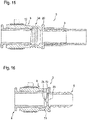
- the figure 15 shows a schematic sectional view of the fluid connection adapter 3.
- the hose nozzle receiving element 6 is designed with an expansion area 34 in which its flexibility is greater than in an area lying outside of the expansion area 34.
- the stretching area 34 as shown here, is implemented by a wavy profile of the wall 12.
- the wall 12 can have a smaller wall thickness in the expansion area 34 than outside of the expansion area 34.
- the figure 16 shows a schematic longitudinal sectional representation of the fluid connection adapter 3 with hose nozzle 2 arranged therein.
- the integration of a non-return valve 35 in the fluid connection adapter 3 is shown.
- the non-return valve 35 is present here in a first embodiment.
- the check valve 35 is provided and designed to interrupt a flow connection through the fluid connection adapter 3 in a first flow direction and to release it in a second flow direction opposite to the first flow direction.
- the check valve 35 has a valve element 36 which interacts or can interact with a valve seat 37 to interrupt the flow connection.
- the valve element 36 is formed by the hose nozzle receiving element 6 of the fluid connection adapter 3, in particular it is made in one piece and of the same material with it. This means that the valve element 36 consists of the same elastic material as the hose nozzle receiving element 6.
- the valve seat 37 is formed by the connecting piece 5, namely by its end face. In a first position of the valve element 36 shown here this is in such a way on the valve seat 37 or on the end face of the connecting piece 5 that the flow connection through the fluid connection adapter 3 is interrupted. In a second position, not shown here, the valve element 36 is at a distance from the valve seat 37, so that the flow connection is released. In the second position, the valve element 36 preferably protrudes into the hose nozzle 2 arranged in the hose nozzle receptacle 11 . This enables a particularly compact and space-saving design of the fluid connection adapter 3.
- the figure 17 shows a further schematic longitudinal sectional view of the fluid connection adapter 3.
- the check valve 35 is again formed, but is present here in a second embodiment.
- the check valve 35 is designed as a duckbill valve, which has at least two valve lips 38 .
- four valve lips 38 are provided, but only two of them can be seen.
- the two valve lips 38 shown are behind the sectional plane, while the two valve lips 38 (not shown) are in front of the sectional plane.
- the valve lips 38 are preferably arranged at a distance from the connecting piece 5 in the axial direction. To this end, they start from a channel wall 39 which delimits a flow channel 40 outwards in the radial direction.
- the valves 38 are preferably designed in one piece and of the same material with the channel wall 39 , which in turn—particularly preferably—is designed in one piece and with the same material as the hose nozzle receiving element 6 .
- the channel wall 39 is arranged at a distance from an inner circumference 41 of the hose nozzle receptacle element 6 in the radial direction, the inner circumference 41 delimiting the hose nozzle receptacle 6 outwards in the radial direction.
- the channel wall 39 and therefore the flow channel 40 are arranged and designed in such a way that after the fluid connection adapter 3 has been mounted on the hose nozzle 2, the hose nozzle 2 engages between the channel wall 39 and the inner circumference 41, i.e. they overlap in the axial direction. This in turn results in a particularly compact configuration of the fluid connection adapter 3 .
- check valve 35 according to the first embodiment or the second embodiment can be applied to all variants of the fluid connection adapter 3 described above.
- the described embodiments, design variants and attachment configurations can be combined with the embodiments of the check valve 35 as desired.
- the fluid connection adapter 3 according to the statements in this description enables the fluid connection of the pipeline 23 to the hose nozzle 2 in a particularly simple and efficient manner, namely exclusively by means of the fluid connection adapter 3 without additional connection and/or connecting elements.
Landscapes
- Engineering & Computer Science (AREA)
- General Engineering & Computer Science (AREA)
- Mechanical Engineering (AREA)
- Manufacturing & Machinery (AREA)
- Quick-Acting Or Multi-Walled Pipe Joints (AREA)
Description
- Die Erfindung betrifft einen Fluidverbindungsadapter, eine Fluidverbindungsanordnung sowie ein Verfahren zum Herstellen eines Fluidverbindungsadapters.
- Ein Fluidverbindungsadapter gemäß dem Oberbegriff des Anspruchs 1 ist aus der
US 2016/0074089 bekannt. - Aus dem Stand der Technik ist beispielsweise die Druckschrift
DE 40 39 054 C1 bekannt. Diese betrifft eine Schlauch-Rohr-Verbindung, bei der das Rohr nahe seinem Ende mit wenigstens einer Halterippe versehen und der Schlauch mit einem Endabschnitt über die Halterippe hinweg auf das Rohr aufgeschoben und mittels einer den Schlauch hinter der Halterippe umgebenden Schelle oder dergleichen festgeklemmt ist. Dabei ist vorgesehen, dass zwischen dem Schlauch und dem Rohr wenigstens in dem zwischen der Halterippe und der Schelle liegenden Bereich ein Dichtungsmaterial angeordnet ist, das seine Dichtfähigkeit in einem Temperaturbereich von wenigstens -40 °C bis +140 °C beibehält. Auf diese Weise ergibt sich auch bei sehr niedrigen, unter dem Gefrierpunkt liegenden Temperaturen von bis zu -40 °C eine hohe Dichtigkeit bei hohem Fluiddruck im Schlauch und Rohr. - Ein Verfahren zum Herstellen der Verbindung besteht darin, dass das Dichtungsmaterial in zähflüssigem Zustand in Form einer das Rohr zwischen Halterippe und Klemmbereich der Schelle umgebenden Materialanhäufung wenigstens bis zur radialen Höhe der Halterippe in der Nähe der Halterippe aufgetragen und der Schlauch vor dem Aushärten des Dichtungsmaterials über die Halterippe und das Dichtungsmaterial hinweg auf das Rohr geschoben wird. Dies erleichtert das Aufschieben des Schlauchs auf das Rohr und einen Ausgleich von Oberflächenrauigkeiten des Rohrs.
- Es ist Aufgabe der Erfindung, einen Fluidverbindungsadapter vorzuschlagen, welcher gegenüber bekannten Fluidverbindungsadaptern Vorteile aufweist, insbesondere auf besonders flexible und einfache Art und Weise eine fluidtechnische Verbindung einer Rohrleitung mit einer Schlauchtülle ermöglicht.
- Dies wird erfindungsgemäß mit einem Fluidverbindungsadapter mit den Merkmalen des Anspruchs 1 erreicht. Der Fluidverbindungsadapter ist zur fluidtechnischen Verbindung der Rohrleitung mit der Schlauchtülle vorgesehen und ausgebildet. Er weist zur fluidtechnischen Verbindung der Rohrleitung mit der Schlauchtülle einen starren Anschlussstutzen zur Kopplung mit der Rohrleitung sowie eine in einem flexiblen Schlauchtüllenaufnahmeelement ausgebildete Schlauchtüllenaufnahme zur Aufnahme der Schlauchtülle auf.
- Als Leitungen zur fluidtechnischen Anbindung einer fluidführenden Einrichtung kommen grundsätzlich Schlauchleitungen und Rohrleitungen infrage. Eine Schlauchleitung hat den Vorteil, dass sie flexibler ist als eine Rohrleitung und entsprechend Relativbewegungen besser ausgleichen kann. Aufgrund ihrer Elastizität lässt sie sich leicht verbauen. Außerdem ermöglicht sie einen gewissen Toleranzausgleich. Zudem ist eine akustische Entkopplung mittels der Schlauchleitung möglich. Insbesondere im Kraftfahrzeugbereich besteht die Schlauchleitung jedoch aus kostenintensiven Materialien beziehungsweise Werkstoffen, beispielsweise um eine bestimmte Beständigkeit gegenüber einem Medium sicherzustellen. Bevorzugt weist die Schlauchleitung einen mehrlagigen Aufbau auf, der beispielsweise in der DIN73411 beschrieben ist.
- Zudem erfordert es die Bauraumsituation in dem Kraftfahrzeug häufig, dass die Schlauchleitung als Formschlauch vorliegt, welcher zur Herstellung aufwändiger Werkzeuge bedarf. Bereits bei kleinsten Änderungen an der Leitungsführung der Schlauchleitung sind neue Teile aus neuen Werkzeugen erforderlich. Ein Formschlauch lässt sich im Nachhinein nicht verformen und ist nur für die vorbestimmte Geometrie verwendbar. Der Formschlauch ist also formstabil. Ein Baukastensystem aus einer Vielzahl von Formschläuchen lässt sich nur unter Inkaufnahme zusätzlicher Verbindungsstellen in der Leitungsführung verwirklichen. Eine derartige Ausgestaltung mit zusätzlichen Verbindungsstellen ist jedoch teuer und beeinflusst neben der Zuverlässigkeit und den Toleranzen auch den Druckverlust in der Schlauchleitung beziehungsweise dem Formschlauch negativ.
- Die Rohrleitung unterscheidet sich von der Schlauchleitung insbesondere hinsichtlich der Steifigkeit, welche wesentlich von den Eigenschaften des jeweiligen Werkstoffs abhängt. Beispielsweise besteht die Rohrleitung aus einem Werkstoff mit einem höheren Elastizitätsmodul und/oder Schubmodul als die Schlauchleitung. Zur ökonomischen Ausbildung eines Leitungssystems, insbesondere mit hoher Variantenvielfalt, ist es daher sinnvoll, bevorzugt eine Rohrleitung beziehungsweise mehrere Rohrleitungen anstelle einer Schlauchleitung beziehungsweise mehrerer Schlauchleitungen einzusetzen. Die Rohrleitung liegt beispielsweise als extrudierte Rohrleitung, vorzugsweise aus Kunststoff, vor. Diese lässt sich durch geeignete Verfahren in verschiedenen Längen und verschiedenen Leitungsverläufen sehr ökonomisch darstellen. Die Rohrleitung lässt sich zudem durch geeignete Schichtaufbauten an die jeweiligen Medien und Temperaturansatzbereiche anpassen. Wenigstens ein Bereich der Rohrleitung, in welchem eine höhere Biege- und/oder Längenelastizität erforderlich ist, kann zum Beispiel als Wellrohrbereich ausgestaltet werden.
- Die vorstehend erwähnte Schlauchtülle ist zur fluidtechnischen Verbindung mit einer Schlauchleitung vorgesehen und ausgebildet. Die Schlauchtülle ist beispielsweise Bestandteil einer fluidführenden Einrichtung, insbesondere einer wasserführenden Einrichtung. Bevorzugt ist die fluidführende Einrichtung Bestandteil eines Kraftfahrzeugs, insbesondere eines Kühlmittelkreislaufs des Kraftfahrzeugs. Sie kann jedoch auch Teil einer Filterspüleinrichtung zur Spülung eines Filters, insbesondere eines Kohlenwasserstofffilters, einer Bremsanlage, insbesondere einer Unterdruckanlage der Bremsanlage, einer Kurbelgehäuseentlüftungseinrichtung, einer Kraftstoffanlage oder einer Reduktionsmitteleinrichtung zur Einbringung von Reduktionsmittel in Abgas sein. Sie kann jedoch auch im Rahmen eines Haushaltsgeräts, einer Wasserinstallation eines Gebäudes oder einer Industrieanlage Anwendung finden.
- Die Verbindung der Schlauchleitung mit der Schlauchtülle kann beispielsweise unmittelbar durch Überschieben der Schlauchleitung mit leichter Aufweitung über die Schlauchtülle und nachfolgender Sicherung der Schlauchleitung an der Schlauchtülle mittels einer Schlauchschelle erfolgen. Die Schlauchtülle ist beispielsweise nach DIN 74304 ausgeführt oder alternativ gemäß einer Betriebsnorm eines Kraftfahrzeugherstellers. In diesen Normen sind Kontur, Haupt- und Vorzugsmaße und Oberflächenanordnungen für die Schlauchtülle geregelt. Weil die Schlauchleitung innen vorzugsweise eine dauerelastische glatte Innenumfangsfläche aufweist, ist die Dichtheit der fluidtechnischen Verbindung der Schlauchleitung mit der Schlauchtülle unmittelbar gewährleistet.
- Die Verbindung zwischen der Schlauchleitung und der Schlauchtülle wird zur Sicherstellung einer ausreichenden Überdruckfestigkeit gegen Abrutschen mit der Schlauchschelle gesichert. Die Schlauchschelle kann beispielsweise ausgeführt sein als Schraubschelle nach DIN 3017 oder als Federbandschelle nach DIN 3021. Die Schlauchschelle kann auch nach einer Betriebsnorm des Kraftfahrzeugherstellers ausgeführt sein. Grundsätzlich ist die Ausgestaltung der Schlauchschelle jedoch beliebig. Zumeist kommt jedoch eine federnde Spannschelle zum Einsatz.
- Für eine fluidtechnische Verbindung der Rohrleitung mit der fluidführenden Einrichtung muss eine geeignete einfache Lösung gefunden werden. Zu unterscheiden sind hier Verbindungen, die nicht lösbar ausgestaltet sind und im Anlieferungszustand des Leitungssystems bereits realisiert beziehungsweise hergestellt sind, und Verbindungen, die erst nach der Anlieferung des Leitungssystems montiert werden, insbesondere manuell montiert werden, und - vorzugsweise - auch manuell servicefähig sind. Die nichtlösbare Verbindung kann durch eine Montage der Rohrleitung auf einem Anschlussstutzen mit einer sogenannten Tannenbaumkontur realisiert werden. An der Tannenbaumkontur kann wenigstens ein elastisches Dichtelement vorliegen, beispielsweise ein O-Ring. Die Verbindungen werden üblicherweise durch ein sogenanntes Aufschlagen hergestellt, nämlich mittels spezifischer Einrichtungen.
- Als manuell montierbare beziehungsweise servicefähige Leitungsverbindung bietet sich eine Schnellkupplung an. Eine derartige Schnellkupplung ist bewährter Stand der Technik. So gibt es sogenannte V-Kupplungen, Kupplungen gemäß SAE-Norm, insbesondere nach SAE J2044, und Kupplungen nach VDA, insbesondere für größere Durchmesser und/oder für Kühlkreislaufanwendungen. Die Rohrleitung kann nach wie vor mittels Aufschlagen auf einen entsprechend ausgestalteten Anschlussstutzen der Schnellkupplung mit dieser verbunden sein. Dabei muss die Rohrleitung jedoch bestimmte Eigenschaften aufweisen, insbesondere entsprechende Anforderungen an Dehnbarkeit, Kriechfestigkeit und dergleichen erfüllen. Auch stoffschlüssige Verbindungen wie Kunststoffschweißen, zum Beispiel Rotationsreibschweißen oder Laserschweißen, oder Kleben, wie zum Beispiel in der Druckschrift
DE 103 36 494 A1 beschrieben, sind umsetzbar. - In jedem Fall ist zur fluidtechnischen Verbindung der fluidführenden Einrichtung mit der Schlauchleitung also eine Schlauchtülle und zur fluidtechnischen Verbindung mit der Rohrleitung ein Anschlussstutzen notwendig. Das bedeutet schlussendlich, dass die fluidführende Einrichtung auf die Verwendung der Schlauchleitung oder der Rohrleitung angepasst werden muss und das jeweilige Verbindungselement, also entweder die Schlauchtülle oder der Anschlussstutzen, an ihr ausgebildet sein muss, um die Schlauchleitung oder die Rohrleitung fluidtechnisch mit ihr verbinden zu können. Um anstelle der Schlauchleitung eine Rohrleitungen mit der fluidführenden Einrichtung verwenden zu können, könnte also die Schlauchtülle durch einen entsprechenden Anschlussstutzen ausgetauscht werden. Dies ist jedoch für langjährig bewährte Standardbauteile, beispielsweise Leitungsthermostate, elektrische Wasserpumpen oder dergleichen, nicht ohne weiteres möglich.
- Auch eine Modifizierung der fluidführenden Einrichtung für den Einsatz einer Schnellkupplung ist nicht ohne weiteres möglich. Hinzu kommt, dass hierbei entstehende Werkzeugkosten enorm sein können, weil Toleranzanforderungen für eine solche Schnellkupplung hoch sind und gegebenenfalls zusätzliche Schieberebenen erforderlich sind. Zudem entsteht eine weitere Bauteilvariante. Des Weiteren verursachen Schnellkupplungen höhere Kosten als eine Schlauchschelle und es muss Bauraum für eine Betätigung und Montage der Schnellkupplung zur Verfügung stehen.
- Ein direktes Aufschieben der Rohrleitung auf die Schlauchtülle und ihre Sicherung mit einer Schlauchschelle ist in der Regel ebenfalls nicht sinnvoll realisierbar. Die Schlauchtülle ist auf die Verwendung einer Schlauchleitung und mithin auf das Vorliegen von Elastomerwerkstoffen abgestimmt. Für das Aufbringen der Rohrleitung auf die Schlauchtülle müsste zum einen die Rohrleitung gedehnt werden. Hierbei sind selbst bei elastischen Rohrleitungen enorme Kräfte erforderlich, sodass eine Handmontage und/oder -demontage nahezu unmöglich ist. Außerdem müsste die Rohrleitung derart elastisch sein, dass sie sich an den Außenumfang der Schlauchtülle anschmiegt, also auch nach dem Überlaufen einer an der Schlauchtülle vorgesehenen Wulst, einer sogenannten Olive. Des Weiteren müsste die Rohrleitung an ihrer Innenumfangsfläche über eine große Dichtfläche mit endlicher Oberflächengüte bei geringen Flächenpressungen zuverlässig abdichten und dauerhaft dicht bleiben. Dies ist ohne eine Innenschicht aus Elastomer kaum möglich und im Falle einer Wiedermontage der Rohrleitung auf der Schlauchtülle, bei der in der Regel bleibende Verformungen der Rohrleitung in einer anderen Lage positioniert werden, nahezu ausgeschlossen. Schließlich muss die Rohrleitung dem dauerhaften lokal begrenzten Anpressdruck einer Rohrschelle gewachsen sein.
- Es könnte nun beispielsweise vorgesehen sein, die Rohrleitung über einen Adapter mit einer Schlauchleitung zu verbinden und diese wiederum an der Schlauchtülle zu befestigen, nämlich auf bekannte Art und Weise mittels einer Schlauchschelle. Eine solche Lösung ist jedoch sehr aufwendig, weist mehrere Schnittstellen mit Undichtigkeitsrisiko auf und benötigt zudem viel Bauraum. Aus diesem Grund ist der Fluidverbindungsadapter derart ausgestaltet, dass er einerseits unmittelbar mit der Rohrleitung und andererseits unmittelbar mit der Schlauchtülle verbunden oder zumindest verbindbar ist, sodass über den Fluidverbindungsadapter eine direkte fluidtechnische Verbindung zwischen der Rohrleitung und der Schlauchtülle hergestellt beziehungsweise herstellbar ist.
- Hierzu verfügt der Fluidverbindungsadapter über den Anschlussstutzen und die Schlauchtüllenaufnahme. Der Anschlussstutzen dient zur Kopplung mit der Rohrleitung und die Schlauchtüllenaufnahme zur Aufnahme der Schlauchtülle. Die Schlauchtüllenaufnahme ist in dem Schlauchtüllenaufnahmeelement ausgebildet, wird also von diesem wenigstens bereichsweise begrenzt, insbesondere in radialer Richtung bezüglich einer Längsmittelachse des Schlauchtüllenaufnahmeelements und oder des Fluidverbindungsadapters. Bevorzugt umgreift das Schlauchtüllenaufnahmeelement die Schlauchtüllenaufnahme in Umfangsrichtung durchgehend.
- Der Anschlussstutzen ist zur fluidtechnischen Verbindung der Rohrleitung mit dem Fluidverbindungsadapter vorgesehen und ausgebildet. Analog hierzu ist die Schlauchtüllenaufnahme zur fluidtechnischen Verbindung der Schlauchtülle mit dem Fluidverbindungsadapter vorgesehen und ausgebildet. Um den unterschiedlichen Eigenschaften der Rohrleitung und der Schlauchtülle gerecht zu werden, ist der Anschlussstutzen starr ausgebildet, wohingegen das Schlauchtüllenaufnahmeelement, in welchem die Schlauchtüllenaufnahme ausgebildet ist, flexibel ist. Das bedeutet, dass der Anschlussstutzen eine höhere Steifigkeit aufweist als das Schlauchtüllenaufnahmeelement, insbesondere aus einem Material besteht, welches einen höheren Elastizitätsmodul und/oder Schubmodul aufweist. Der Anschlussstutzen und das Schlauchtüllenaufnahmeelement sind vorzugsweise einstückig miteinander ausgebildet, also besonders bevorzugt stoffschlüssig miteinander verbunden. Insbesondere sind der Anschlussstutzen und das Schlauchtüllenaufnahmeelement fest und unlösbar miteinander verbunden, sodass ein zerstörungsfreies Trennen des Anschlussstutzens von dem Schlauchtüllenaufnahmeelement nicht möglich und auch nicht vorgesehen ist.
- Eine bevorzugte Weiterbildung der Erfindung sieht vor, dass der Anschlussstutzen als Rohrtülle ausgestaltet ist und wenigstens einen Ringvorsprung zum Befestigen der Rohrleitung aufweist. Zur Herstellung der fluidtechnischen Verbindung des Fluidverbindungsadapters mit der Rohrleitung ist die Rohrtülle vorgesehen und ausgebildet. Die Rohrtülle verfügt über den wenigstens einen Ringvorsprung, welcher der Befestigung der Rohrleitung an der Rohrtülle dient. Der Ringvorsprung ist vorzugsweise derart ausgestaltet, dass er entgegen einer Aufschubrichtung der Rohrleitung auf die Rohrtülle eine Auflaufschräge aufweist und insoweit schräg und - vorzugsweise - kontinuierlich ansteigt, sodass das Aufschieben der Rohrleitung auf die Rohrtülle vereinfacht. Anschließend an die Auflaufschräge tritt der Ringvorsprung vorzugsweise senkrecht bezüglich einer Längsmittelachse des Anschlussstutzens beziehungsweise der Rohrtülle in radialer Richtung nach innen zurück, sodass ein Tannenbaumprofil ausgebildet oder zumindest teilweise ausgebildet ist.
- Die Schlauchtülle weist analog zu dem als Rohrtülle ausgebildeten Anschlussstutzen vorzugsweise ebenfalls einen Ringvorsprung auf. Der Ringvorsprung der Schlauchtülle ist jedoch nach Art einer Olive ausgebildet und weist insoweit im Längsschnitt bezüglich einer Längsmittelachse der Schlauchtülle gesehen eine durchgehend gekrümmte Außenkontur auf. Im Längshalbschnitt gesehen ist die Olive insoweit zumindest näherungsweise wie eine Halbellipse ausgebildet. Die Ausgestaltung des Anschlussstutzens als Rohrtülle und das Vorsehen des wenigstens einen Ringvorsprungs ermöglicht eine zuverlässige und dauerhafte Anbindung der Rohrleitung an den Fluidverbindungsadapter.
- Eine weitere Ausgestaltung der Erfindung sieht vor, dass an dem Anschlussstutzen wenigstens eine Dichtung zur fluiddichten Kopplung mit der Rohrleitung angeordnet ist. Beispielsweise verfügt der Anschlussstutzen über eine Dichtungsaufnahme, in welcher die Dichtung vorliegt. Die Dichtungsaufnahme ist vorzugsweise in Umfangsrichtung durchgehend ausgebildet, umgreift also die Längsmittelachse des Anschlussstutzens in Umfangsrichtung durchgehend. Die Dichtungsaufnahme ist besonders bevorzugt kanalartig ausgebildet und wird insoweit in radialer Richtung nach innen von einem vorzugsweise vollständig oder zumindest bereichsweise planen Grund und in axialer Richtung beiderseits von jeweils einer Seitenwand begrenzt, wobei die Seitenwände jeweils senkrecht auf dem Grund stehen. Beispielsweise wird eine der Seitenwände von dem vorstehend beschriebenen Ringvorsprung gebildet. Die Dichtung liegt insbesondere in Form eines Dichtrings, beispielsweise eine O-Rings, vor. Mittels der Dichtung wird eine dauerhafte und zuverlässige dichte fluidtechnische Verbindung zwischen der Rohrleitung und dem Fluidverbindungsadapter sichergestellt.
- Eine Weiterbildung der Erfindung sieht vor, dass eine die Schlauchtüllenaufnahme begrenzende Wand des Schlauchtüllenaufnahmeelements auf Seiten der Schlauchtüllenaufnahme profiliert ist. Die Wand begrenzt die Schlauchtüllenaufnahme vorzugsweise in radialer Richtung nach außen bezüglich der Längsmittelachse des Schlauchtüllenaufnahmeelements beziehungsweise der Schlauchtüllenaufnahme. Die profilierte Ausgestaltung der Wand wird beispielsweise durch Ausbildung wenigstens einer Halteaufnahme realisiert, welche in Form einer Ausnehmung in der Wand ausgebildet ist. Die Halteaufnahme dient der Aufnahme wenigstens eines Haltevorsprungs der Schlauchtülle, beispielsweise der vorstehend bereits erwähnten Olive. Es kann jedoch auch vorgesehen sein, dass mehrere Halteaufnahmen in der Wand ausgebildet sind, nämlich in axialer Richtung beabstandet voneinander.
- Vorzugsweise weist bei einer derartigen Ausgestaltung der Schlauchtüllenaufnahme beziehungsweise des Schlauchtüllenaufnahmeelements die Schlauchtülle eine Anzahl an Haltevorsprüngen auf, die der Anzahl der Halteaufnahmen entspricht. Beispielsweise liegen insoweit mehrere in axialer Richtung voneinander beabstandete Oliven an der Schlauchtülle vor. Eine solche Schlauchtülle liegt beispielsweise an einem Schnellverbinder vor, insbesondere an einem Schnellverbinder mit Metallgehäuse. Die beschriebene Ausgestaltung des Schlauchtüllenaufnahmeelements beziehungsweise seiner Wand und/oder der Schlauchtülle ermöglicht eine in axialer Richtung besonders stabile und zuverlässige Verbindung zwischen dem Fluidverbindungsadapter und der Schlauchtülle.
- Eine bevorzugte Weiterbildung der Erfindung sieht vor, dass der Anschlussstutzen aus einem ersten Material und das Schlauchtüllenaufnahmeelement aus einem von dem ersten Material verschiedenen zweiten Material besteht. Der Anschlussstutzen und das Schlauchtüllenaufnahmeelement sind insoweit materialuneinheitlich ausgestaltet. Insbesondere ist das erste Material derart gewählt, dass der Anschlussstutzen besonders zuverlässig und dicht mit der Rohrleitung verbindbar ist. Analog hierzu ist das zweite Material vorzugsweise derart gewählt, dass die Schlauchtülle besonders zuverlässig und dauerhaft dicht in der von dem Schlauchtüllenaufnahmeelement ausgebildeten Schlauchtüllenaufnahme aufgenommen ist, sodass insgesamt eine zuverlässige und dichte fluidtechnische Verbindung zwischen der Rohrleitung und der Schlauchtülle über den Fluidverbindungsadapter hergestellt ist.
- Eine weitere Ausführungsform der Erfindung sieht vor, dass das zweite Material eine größere Flexibilität aufweist als das erste Material. In anderen Worten weist das zweite Material beispielsweise einen kleineren Elastizitätsmodul und/oder einen kleineren Schubmodul auf als das erste Material. Eine derartige Ausgestaltung des Fluidverbindungsadapters ermöglicht eine besonders gute Anpassung an die Rohrleitung einerseits sowie die Schlauchtülle andererseits. Während der Anschlussstutzen zur fluidtechnischen Verbindung mit der Rohrleitung starr ist und insoweit eine höhere Steifigkeit aufweist als das Schlauchtüllenaufnahmeelement, ist das Schlauchtüllenaufnahmeelement flexibler ausgebildet, sodass es nach Art einer Schlauchleitung mit der Schlauchtülle verbindbar ist. Hierdurch wird eine dauerhaft fluiddichte Verbindung hergestellt.
- Zusätzlich oder alternativ kann vorgesehen sein, dass das erste Material ein Elastomer und das zweite Material ein Thermoplast oder ein Duroplast ist. Sowohl das Elastomer als auch der Thermoplast beziehungsweise der Duroplast können grundsätzlich beliebig gewählt sein. Bevorzugt liegt der Elastomer jedoch in Form eines Ethylen-Propylen-Dien-Kautschuks (EPDM) oder eines hydrierten Acrylnitril-Butadien-Kautschuks (HMBR) vor, wobei letzterer besonders bevorzugt peroxidisch vernetzt ist, um eine hohe Medienbeständigkeit zu erzielen. Das zweite Material kann beispielsweise ein partiell aromatisches Polyamid (PPA) beziehungsweise Polyphthalamid, Polyamid, insbesondere PA612 oder Polypropylen (PP) sein. Bevorzugt ist das zweite Material faserverstärkt, insbesondere glasfaserverstärkt oder kohlefaserverstärkt.
- Zusätzlich oder alternativ kann das zweite Material hydrolysestabilisiert sein. Auch das erste Material kann grundsätzlich faserverstärkt und/oder hydrolysestabilisiert sein. Besonders bevorzugt ist es vorgesehen, dass das erste Material oder das zweite Material oder sowohl das erste Material als auch das zweite Material haftungsoptimiert sind. Als Beispiel für ein haftungsoptimiertes Material wird rein beispielhaft VESTAMID HTplus, insbesondere VESTAMID HTplus R1033 des Unternehmens Evonik Industries AG angeführt.
- Im Rahmen einer weiteren Ausführungsform der Erfindung kann vorgesehen sein, dass das Schlauchtüllenaufnahmeelement auf seiner der Schlauchtüllenaufnahme abgewandten Seite eine Schlauchschellenaufnahme zur Aufnahme einer Schlauchschelle aufweist. Das bedeutet, dass der Fluidverbindungsadapter zur Befestigung an der Schlauchtülle mittels der Schlauchschelle vorgesehen und ausgebildet ist. Zur abrutschsicheren Befestigung der Schlauchschelle an dem Schlauchtüllenaufnahmeelement ist die Schlauchschellenaufnahme an diesem ausgebildet, nämlich auf seiner der Schlauchtüllenaufnahme abgewandten Außenseite.
- Die Schlauchschellenaufnahme ist in axialer Richtung wenigstens einseitig, vorzugsweise jedoch beidseitig, (jeweils) mittels eines Ringstegs begrenzt. Im Falle der beidseitigen Begrenzung der Schlauchschellenaufnahme mittels der mehreren Ringstege sind die Ringstege vorzugsweise in axialer Richtung derart voneinander beabstandet, dass die Schlauchschelle nach Anordnung an dem Fluidverbindungsadapter und insbesondere nach Befestigung des Fluidverbindungsadapters an der Schlauchtülle mittels der Schlauchschelle einerseits an einem ersten der Ringstege und andererseits an einem zweiten der Ringstege anliegt. Eine solche Ausgestaltung des Schlauchtüllenaufnahmeelements verhindert ein ungewolltes Abrutschen der Schlauchschelle von dem Schlauchtüllenaufnahmeelement und stellt insoweit eine zuverlässige und dauerhafte dichte Verbindung zwischen dem Fluidverbindungsadapter und der Schlauchtülle sicher.
- Eine weitere Ausführungsform der Erfindung sieht vor, dass die Schlauchtüllenaufnahme Innenquerschnittsabmessungen aufweist, die sich ausgehend von Innenquerschnittsabmessungen des Anschlussstutzens auf seiner dem Schlauchtüllenaufnahmeelement zugewandten Seite in die von dem Anschlussstutzen abgewandte Richtung vergrößern. Sowohl in dem Anschlussstutzen als auch in dem Schlauchtüllenaufnahmeelement liegt jeweils eine Durchtrittsöffnung beziehungsweise ein Hohlraum vor, wobei die Durchtrittsöffnungen beziehungsweise Hohlräume ineinander übergehen oder zumindest miteinander in Strömungsverbindung stehen. Die Durchtrittsöffnung des Anschlussstutzens ist fluidführend, wohingegen die Durchtrittsöffnung des Schlauchtüllenaufnahmeelements zumindest bereichsweise die Schlauchtüllenaufnahme ausbildet.
- Die Durchtrittsöffnungen des Anschlussstutzens und des Schlauchtüllenaufnahmeelements zeichnen sich durch die jeweiligen Innenquerschnittsabmessungen aus. Die Innenquerschnittsabmessungen des Anschlussstutzens sind beispielsweise in Strömungsrichtung beziehungsweise in axialer Richtung über die gesamte Erstreckung des Anschlussstutzens konstant. Die Innenquerschnittsabmessungen der Schlauchtüllenaufnahme hingegen verändern sich über die Erstreckung der Schlauchtüllenaufnahme beziehungsweise des Schlauchtüllenaufnahmeelements hinweg jedoch. So entsprechen sie an dem Übergang zwischen dem Schlauchtüllenaufnahmeelement und dem Anschlussstutzen beispielsweise den Innenquerschnittsabmessungen des Anschlussstutzens. Alternativ können sie auch größer sein, sodass eine sprungartige Vergrößerung der Innenquerschnittsabmessungen an dem Übergang von dem Anschlussstutzen zu dem Schlauchtüllenaufnahmeelement auftritt.
- In jedem Fall vergrößern sich die Innenquerschnittsabmessungen der Schlauchtüllenaufnahme in die von dem Anschlussstutzen abgewandte Richtung. Mit einer derartigen Ausgestaltung des Fluidverbindungsadapters wird sichergestellt, dass der Fluidverbindungsadapter zur Anbindung an eine Schlauchtülle geeignet ist, die Innenquerschnittsabmessungen aufweist, die zumindest so groß sind wie die des Anschlussstutzens. Besonders bevorzugt ist der Fluidverbindungsadapter derart ausgestaltet, dass die Innenquerschnittsabmessungen der in der Schlauchtüllenaufnahme aufgenommenen Schlauchtülle den Innenquerschnittsabmessungen des Anschlussstutzens entsprechen, sodass also ein Durchströmungsquerschnitt der Schlauchtülle mit einem Durchströmungsquerschnitt des Anschlussstutzens übereinstimmt oder größer ist. Auf diese Art und Weise werden Strömungsverluste in dem Fluidverbindungsadapter verhindert.
- Eine weitere Ausführungsform der Erfindung sieht vor, dass das Aufweiten der Innenquerschnittsabmessungen stetig erfolgt, insbesondere über eine axiale Erstreckung, die um mindestens einen Faktor von 0,5, 1,0, 1,5 oder 2,0 größer ist als eine Differenz zwischen den Innenquerschnittsabmessungen der Schlauchtüllenaufnahme und den Innenquerschnittsabmessungen des Anschlussstutzens. In anderen Worten ist ein sanftes und nicht sprunghaftes Aufweiten der Innenquerschnittsabmessungen vorgesehen und umgesetzt. Beispielsweise ist die Schlauchtüllenaufnahme auf ihrer dem Anschlussstutzen zugewandten Seite zumindest bereichsweise kegelstumpfförmig, wobei die die Schlauchtüllenaufnahme begrenzende Wand auf ihrer der Schlauchtüllenaufnahme zugewandte Seite im Längsschnitt beziehungsweise Längshalbschnitt gesehen eine konstante Steigung aufweist.
- Bevorzugt ist zusätzlich der Fluidverbindungsadapter derart ausgestaltet, dass eine maximale Einstecktiefe der Schlauchtülle in die Schlauchtüllenaufnahme derart ist, dass bei in die Schlauchtüllenaufnahme eingesteckter Schlauchtülle die Schlauchtülle erst nach dem vollständigen Aufweiten der Innenquerschnittsabmessungen beginnt. In anderen Worten ist der Fluidverbindungsadapter derart ausgestaltet, dass bei bestimmungsgemäß in der Schlauchtüllenaufnahme angeordneter Schlauchtülle die Schlauchtülle außerhalb des Aufweitungsbereichs angeordnet ist. Mit einer derartigen Ausgestaltung wird ein besonders geringer Strömungswiderstand des Fluidverbindungsadapters sichergestellt.
- Die Erfindung sieht vor, dass der Anschlussstutzen von einem, insbesondere ringförmigen, Basiselement ausgeht, das an dem Schlauchtüllenaufnahmeelement befestigt ist. Das Schlauchtüllenaufnahmeelement ist unmittelbar an dem Basiselement befestigt. Der Anschlussstutzen liegt beabstandet von dem Schlauchtüllenaufnahmeelement auf der dem Schlauchtüllenaufnahmeelement abgewandten Seite des Basiselements vor und erstreckt sich ausgehend von dem Basiselement in die von dem Schlauchtüllenaufnahmeelement abgewandte Richtung. Vorzugsweise fällt eine Längsmittelachse des Anschlussstutzens mit einer Längsmittelachse des Basiselements zusammen. Dies gilt insbesondere im Falle der ringförmigen Ausgestaltung des Basiselements. In letzterem Fall ist das Basiselement nach Art eines Ringkragens an dem Anschlussstutzen ausgebildet und erstreckt sich ausgehend von diesem in radialer Richtung nach außen. Die Verwendung des Basiselements ermöglicht eine besonders zuverlässige Befestigung des Anschlussstutzens an dem Schlauchtüllenaufnahmeelement.
- Eine bevorzugte weitere Ausführungsform der Erfindung sieht vor, dass das Schlauchtüllenaufnahmeelement und der Anschlussstutzen koaxial angeordnet sind, oder dass das Schlauchtüllenaufnahmeelement bezüglich des Anschlussstutzens angewinkelt ist. In ersterem Fall fällt eine Längsmittelachse des Schlauchtüllenaufnahmeelements mit einer Längsmittelachse des Anschlussstutzens zusammen. In letzterem Fall ist die Längsmittelachse des Schlauchtüllenaufnahmeelements bezüglich der Längsmittelachse des Anschlussstutzens angewinkelt oder windschief zu ihr angeordnet. Der Fluidverbindungsadapter kann also gerade oder angewinkelt ausgestaltet sein, sodass eine besonders flexible Anpassung an dem Einbauort des Fluidverbindungsadapters gegeben ist. Bei der angewinkelten Ausgestaltung schneiden sich die Längsmittelachsen der Schlauchtüllenaufnahme und des Anschlussstutzens beispielsweise unter einem Winkel, der größer als 0° und kleiner als 180° ist. Bevorzugt beträgt der Winkel 45°, 90° oder 135°.
- Eine Weiterbildung der Erfindung sieht vor, dass das Schlauchtüllenaufnahmeelement mit dem Anschlussstutzen formschlüssig und/oder stoffschlüssig verbunden ist, insbesondere an den Anschlussstutzen angespritzt ist. In jedem Fall ist das Schlauchtüllenaufnahmeelement fluiddicht mit dem Anschlussstutzen verbunden. Grundsätzlich ist eine formschlüssige oder stoffschlüssige Verbindung des Schlauchtüllenaufnahmeelements mit dem Anschlussstutzen hinreichend, um einerseits eine zufriedenstellende Stabilität des Fluidverbindungsadapters und andererseits eine hervorragende Dichtheit sicherzustellen. Die stoffschlüssige Verbindung wird beispielsweise durch Anspritzen des Schlauchtüllenaufnahmeelements an den Anschlussstutzen hergestellt. Besonders bevorzugt ist jedoch die Verbindung sowohl formschlüssig als auch stoffschlüssig.
- Die Erfindung sieht vor, dass an dem Basiselement wenigstens ein in das Schlauchtüllenaufnahmeelement eingreifender erster Vorsprung und/oder mehrere in das Schlauchtüllenaufnahmeelement eingreifende zweite Vorsprünge ausgebildet sind. Der erste Vorsprung und/oder die mehreren zweiten Vorsprünge dienen der Anbindung des Schlauchtüllenaufnahmeelements an den Anschlussstutzen beziehungsweise umgekehrt. Der erste Vorsprung und/oder die zweiten Vorsprünge gehen von dem Basiselement aus, insbesondere erstrecken sie sich in die von dem Anschlussstutzen abgewandte Richtung. Vorzugsweise sind der erste Vorsprung und/oder die zweiten Vorsprünge mit dem Schlauchtüllenaufnahmeelement umspritzt. Das bedeutet, dass der erste Vorsprung und/oder die zweiten Vorsprünge vollständig in dem Schlauchtüllenaufnahmeelement aufgenommen sind, soweit sie über das Basiselement überstehen.
- Hierzu ist das Schlauchtüllenaufnahmeelement an das Basiselement angespritzt, nämlich derart, dass der erste Vorsprung und/oder die zweiten Vorsprünge in dem Schlauchtüllenaufnahmeelement angeordnet beziehungsweise von diesem aufgenommen sind. Auf diese Art und Weise wird eine besonders zuverlässige Verbindung zwischen dem Anschlussstutzen und dem Schlauchtüllenaufnahmeelement erzielt. Beispielsweise ist lediglich ein einziger erster Vorsprung an dem Basiselement ausgebildet. Besonders bevorzugt liegen jedoch mehrere erste Vorsprünge an dem Basiselement vor. Sofern mehrere erste Vorsprünge vorliegen, sind diese besonders bevorzugt gleichmäßig über den Umfang des Basiselements hinweg verteilt angeordnet. Dies kann ebenso für die zweiten Vorsprünge gelten.
- Beispielsweise ist es vorgesehen, dass der wenigstens eine erste Vorsprung in axialer Richtung ausgehend von dem Basiselement eine größere Erstreckung aufweist als die zweiten Vorsprünge. Beispielsweise beträgt die Erstreckung der zweiten Vorsprünge in axialer Richtung beziehungsweise in die von dem Anschlussstutzen abgewandte Richtung bezogen auf die Erstreckung des wenigstens einen ersten Vorsprungs in diese Richtung höchstens 5 %, höchstens 10 %, höchstens 15 %, höchstens 20 % oder höchstens 25 %.
- Die Erfindung sieht vor, dass der erste Vorsprung aus mehreren Stegen besteht, die beabstandet voneinander an dem Basiselement angreifen und auf ihrer dem Basiselement abgewandten Seite aneinander befestigt sind, sodass zwischen den Stegen wenigstens eine Öffnung vorliegt. Der erste Vorsprung weist insoweit wenigstens zwei Stege, vorzugsweise jedoch drei Stege, oder vier Stege auf. Zumindest ein Teil der Stege des ersten Vorsprungs oder alle Stege gehen von dem Basiselement aus. Alle Stege des ersten Vorsprungs sind auf ihrer dem Basiselement abgewandten Seite miteinander verbunden beziehungsweise aneinander befestigt. Hierbei sind die Stege jedoch derart beabstandet voneinander angeordnet, sodass zwischen wenigstens zwei der Stege eine Öffnung vorliegt, insbesondere eine spaltartige Öffnung. Vorzugsweise ist zwischen jedem der Stege des ersten Vorsprungs und einem unmittelbar benachbart zu ihm angeordneten der Stege eine solche Öffnung ausgebildet.
- Es kann vorgesehen sein, dass lediglich ein Teil der Stege des ersten Vorsprungs an dem Basiselement angreifen beziehungsweise von diesem ausgehen. In diesem Fall verfügt der erste Vorsprung über wenigstens einen Steg, vorzugsweise mehrere Stege, die an den von dem Basiselement ausgehenden Stegen befestigt sind und sich in Richtung des Basiselements erstrecken, jedoch von diesem beabstandet enden. Dieser Steg beziehungsweise diese Stege sind mit einem korrespondierenden Steg beziehungsweise korrespondierenden Stegen eines anderen ersten Vorsprungs verbrunden. Eine derartige Ausgestaltung ermöglicht eine besonders zuverlässige und dennoch flexible Verbindung des Anschlussstutzens mit dem Schlauchtüllenaufnahmeelement. Eine bevorzugte weitere Ausgestaltung der Erfindung sieht vor, dass der wenigstens eine erste Vorsprung zumindest eine Ausnehmung zur bereichsweisen Aufnahme des Schlauchtüllenaufnahmeelements aufweist. Die Ausnehmung liegt insbesondere in Form einer Bohrung vor, welche beispielsweise als Sackbohrung oder als Durchtrittsbohrung ausgestaltet sein kann. Vorzugsweise weist der erste Vorsprung eine Vielzahl derartiger Ausnehmungen auf. Sind mehrere erste Vorsprunge vorgesehen, so liegen die wenigstens eine Ausnehmung beziehungsweise die mehreren Ausnehmungen bevorzugt an jedem der ersten Vorsprünge vor.
- Die Ausnehmung beziehungsweise die Ausnehmungen sind derart ausgestaltet, dass nach der Anbindung des Schlauchtüllenaufnahmeelements an den Anschlussstutzen das Schlauchtüllenaufnahmeelement bereichsweise in ihnen aufgenommen ist. Beispielsweise wird das Schlauchtüllenaufnahmeelement derart an den Anschlussstutzen beziehungsweise das Basiselement angespritzt, dass die zumindest eine Ausnehmung von dem Material des Schlauchtüllenaufnahmeelements durchsetzt wird. Hierdurch wird eine besonders zuverlässige Anbindung des Schlauchtüllenaufnahmeelements an den Anschlussstutzen erzielt, nämlich eine formschlüssige.
- Zusätzlich oder alternativ kann vorgesehen sein, dass der wenigstens eine erste Vorsprung flexibler ist als das Basiselement und/oder der Anschlussstutzen. Hierzu weist der erste Vorsprung vorzugsweise eine geringere Materialstärke auf als das Basiselement beziehungsweise der Anschlussstutzen. Somit wird eine einerseits flexible Anbindung des Schlauchtüllenaufnahmeelements an den Anschlussstutzen erzielt, welche andererseits äußerst dauerhaft ist. Eine weitere bevorzugte Ausgestaltung der Erfindung sieht vor, dass der wenigstens eine erste Vorsprung das Schlauchtüllenaufnahmeelement in axialer Richtung zumindest 25 %, mindestens 50 %, mindestens 75 %, mindestens 80 %, mindestens 85 % oder mindestens 90 % durchgreift. Der erste Vorsprung erstreckt sich also so weit in die von dem Anschlussstutzen abgewandte Richtung, dass das Schlauchtüllenaufnahmeelement zumindest bereichsweise, insbesondere größtenteils oder sogar überwiegend, durchgriffen ist. Eine derartige Ausgestaltung ermöglicht eine zuverlässige Anbindung des Anschlussstutzens an die Schlauchtülle mittels des Fluidverbindungsadapters.
- Dies wird insbesondere dadurch erzielt, dass der mindestens eine erste Vorsprung im Längsschnitt gesehen zumindest teilweise mit der Schlauchschellenaufnahme in Überdeckung steht, insbesondere die Schlauchschellenaufnahme im Längsschnitt gesehen vollständig überdeckt. In anderen Worten ist es vorgesehen, dass nach der Befestigung des Fluidverbindungsadapters an der Schlauchtülle mittels der Schlauchschelle die Schlauchschelle den ersten Vorsprung zumindest bereichsweise beaufschlagt, insbesondere in radialer Richtung nach innen in Richtung der Schlauchtülle drängt. Auf diese Art und Weise ist der Anschlussstutzen beziehungsweise das Basiselement nicht nur mittelbar über das Schlauchtüllenaufnahmeelement an die Schlauchtülle angebunden, sondern vielmehr mittels der Schlauchschelle unmittelbar bezüglich der Schlauchtülle gehalten.
- Eine bevorzugte weitere Ausführungsform der Erfindung sieht vor, dass die zweiten Vorsprünge ringförmig bezüglich einer Längsmittelachse des Basiselements angeordnet sind und/oder dass die zweiten Vorsprünge abwechselnd in radialer Richtung versetzt zueinander angeordnet sind. Die zweiten Vorsprünge umgreifen also die Längsmittelachse des Basiselements nach Art eines Rings. Hierzu sind sie vorzugsweise in Umfangsrichtung gleichmäßig verteilt angeordnet. Zusätzlich oder alternativ kann es vorgesehen sein, dass die zweiten Vorsprünge abwechselnd in radialer Richtung versetzt zueinander angeordnet sind, also abwechselnd an einer ersten Radialposition und einer zweiten Radialposition angeordnet sind, wobei die zweite Radialposition von der ersten Radialposition verschieden ist. In anderen Worten ist in Umfangsrichtung gesehen ein mäanderförmiger Verlauf der zweiten Vorsprünge realisiert. Beispielsweise greifen die zweiten Vorsprünge in eine an dem Basiselement ausgebildete Vertiefung ein, welche ebenfalls in Umfangsrichtung mäanderförmig verläuft. Auf diese Art und Weise ist ein besonders zuverlässiges Halten des Schlauchtüllenaufnahmeelements dem Anschlussstutzen beziehungsweise dem Basiselement sichergestellt.
- Eine weitere Ausführungsform der Erfindung sieht vor, dass das Schlauchtüllenaufnahmeelement einen Dehnungsbereich aufweist, indem eine Flexibilität des Schlauchtüllenaufnahmeelements, insbesondere in axialer Richtung, größer ist als in einem außerhalb des Dehnungsbereichs liegenden Bereich des Schlauchtüllenaufnahmeelements. Der Dehnungsbereich ist beispielsweise zur Realisierung eines Toleranzausgleichs vorgesehen und ausgebildet. Der Dehnungsbereich kann eine Dehnung des Schlauchtüllenaufnahmeelements in axialer Richtung derart zulassen, dass entweder eine axiale Längung des Schlauchtüllenaufnahmeelements oder eine Biegung des Schlauchtüllenaufnahmeelements vorliegt.
- In anderen Worten können mittels des Dehnungsbereichs ein Axialversatz und/oder ein Winkelversatz ausgeglichen werden. Der Dehnungsbereich ist durch eine bereichsweise höhere Flexibilität des Schlauchtüllenaufnahmeelements ausgebildet. Vorzugsweise ist der Dehnungsbereich in axialer Richtung beidseitig randbeabstandet an dem Schlauchtüllenaufnahmeelement ausgebildet, sodass der Dehnungsbereich in axialer Richtung von Enden des Schlauchtüllenaufnahmeelements beabstandet angeordnet ist. Der Dehnungsbereich ermöglicht auf besonders einfache Art und Weise den vorstehend bereits erwähnten Axialversatzausgleich und/oder Winkelversatzausgleich.
- Eine bevorzugte Weiterbildung der Erfindung sieht vor, dass der wenigstens eine Vorsprung und/oder die zweiten Vorsprünge beabstandet von dem Dehnungsbereich angeordnet sind. In anderen Worten ist umgekehrt der Dehnungsbereich abseits des wenigstens einen Vorsprungs beziehungsweise der zweiten Vorsprünge angeordnet. Entsprechend beeinflussen die Vorsprünge die Flexibilität des Schlauchtüllenaufnahmeelements in dem Dehnungsbereich nicht oder zumindest nicht wesentlich. Der zuverlässige Ausgleich des Längenversatzes beziehungsweise des Winkelversatzes ist somit gewährleistet.
- Eine weitere Ausführungsform der Erfindung sieht vor, dass der Dehnungsbereich zwischen der Schlauchtüllenaufnahme und einem an dem Basiselement angreifenden Ende des Schlauchtüllenaufnahmeelements vorliegt. Nach bestimmungsgemäßem Verbinden des Fluidverbindungsadapters mit der Schlauchtülle ist also letztere zumindest über den Dehnungsbereich von dem Anschlussstutzen beziehungsweise dem Basiselement beabstandet. Aufgrund des zwischen der Schlauchtüllenaufnahme beziehungsweise der Schlauchtülle einerseits und dem Basiselement andererseits angeordneten Dehnungsbereich ist ein hervorragender Versatzausgleich mittels des Fluidverbindungsadapters sichergestellt.
- Eine weitere bevorzugte Ausgestaltung der Erfindung sieht vor, dass die Wand des Schlauchtüllenaufnahmeelements in dem Dehnungsbereich wellenförmig verläuft und/oder eine geringere Wandstärke aufweist als außerhalb des Dehnungsbereichs. Durch den im Längsschnitt gesehen wellenförmigen Verlauf der Wand und/oder die geringere Wandstärke wird die höhere Flexibilität in dem Dehnungsbereich realisiert. Der wellenförmige Verlauf lässt insbesondere eine Dehnung des Dehnungsbereichs in axialer Richtung ohne weiteres zu. Es kann vorgesehen sein, dass die wellenförmig verlaufende Wand in dem Dehnungsbereich dieselbe Wandstärke aufweist wie außerhalb des Dehnungsbereichs. Es kann jedoch auch vorgesehen sein, dass die Wand die im Vergleich mit der außerhalb des Dehnungsbereichs vorliegenden Wandstärke geringere Wandstärke zusätzlich zu dem wellenförmigen Verlauf aufweist. In jedem Fall ist der Dehnungsbereich hinreichend flexibel, um einen Versatzausgleich zu realisieren.
- Im Rahmen einer weiteren Ausführungsform ist ein Rückschlagventil vorgesehen, dass eine Strömungsverbindung durch den Fluidverbindungsadapter bei einer ersten Durchströmungsrichtung unterbricht und bei einer der ersten Durchströmungsrichtung entgegengesetzten zweiten Durchströmungsrichtung freigibt. Das Rückschlagventil ist in den Fluidverbindungsadapter integriert, wodurch sich bauliche Vorteile ergeben. Das Rückschlagventil ist gemäß der üblichen Funktion eines solchen Rückschlagventils derart ausgestaltet, dass es eine Durchströmung des Fluidverbindungsadapter in der ersten Durchströmungsrichtung unterbricht und in der zweiten Durchströmungsrichtung freigibt, wobei die zweite Durchströmungsrichtung der ersten Durchströmungsrichtung entgegengerichtet ist. Es kann vorgesehen sein, dass das Rückschlagventil die Strömungsverbindung bei Vorliegen der ersten Durchströmungsrichtung vollständig unterbricht. Es kann jedoch auch vorgesehen sein, dass ein Leckagestrom durch das Rückschlagventil auch bei Vorliegen der ersten Durchströmungsrichtung zugelassen wird.
- Das Rückschlagventil verfügt vorzugsweise über ein Ventilelement, welches bei der ersten Durchströmungsrichtung eine erste Stellung und bei der zweiten Durchströmungsrichtung eine zweite Stellung einnimmt. In der ersten Stellung unterbricht das Ventilelement die Strömungsverbindung durch den Fluidverbindungsadapter, beispielsweise durch Zusammenwirken mit einem Ventilsitz, insbesondere durch Anliegen an dem Ventilsitz. In der zweiten Stellung gibt das Ventilelement hingegen die Strömungsverbindung durch den Fluidverbindungsadapter frei, beispielweise ist es hierzu zumindest bereichsweise oder sogar vollständig von dem Ventilsitz beabstandet angeordnet.
- Eine bevorzugt weitere Ausgestaltung der Erfindung sieht vor, dass das Rückschlagventil einen Ventilsitz und ein mit dem Ventilsitz zum Unterbrechen der Strömungsverbindung zusammenwirkendes Ventilelement aufweist. Hierauf wurde vorstehend bereits hingewiesen. Die Ausgestaltung des Rückschlagventils mit Ventilsitz und Ventilelement ist konstruktiv einfach und kostengünstig umsetzbar. Vorzugsweise ist das Ventilelement derart ausgestaltet, dass es druckstabil gegenüber einem in die erste Durchströmungsrichtung wirkenden Überdruck ist. Hierzu ist es beispielsweise kugelabschnittsförmig oder rotationsparaboloidförmig ausgestaltet.
- Eine bevorzugte Weiterbildung der Erfindung sieht vor, dass das Ventilelement von dem Schlauchtüllenaufnahmeelement gebildet ist, und/oder dass der Ventilsitz von dem Anschlussstutzen gebildet ist. Bevorzugt ist das Ventilelement einstückig und/oder materialeinheitlich mit dem Schlauchtüllenaufnahmeelement ausgebildet. Vorzugsweise ragt das Ventilelement in die Schlauchtüllenaufnahme hinein. Dies ermöglicht eine besonders einfache und kostengünstige Ausgestaltung des Rückschlagventils. Zusätzlich oder alternativ kann der Ventilsitz von dem Anschlussstutzen gebildet sein. Zur Bereitstellung des Rückschlagventils ist also kein separater Ventilsitz herzustellen, vielmehr wird der Ventilsitz von dem Anschlussstutzen, insbesondere von einer Stirnseite des Anschlussstutzens, gebildet. Zum Unterbrechen der Strömungsverbindung kann sich das Ventilelement dichtend an den Anschlussstutzen beziehungsweise dessen Stirnseite anlegen.
- Besonders bevorzugt ist das Ventilelement als Ventilklappe ausgebildet. Das bedeutet, dass das Ventilelement um eine Drehachse drehbar gelagert ist, insbesondere an dem Schlauchtüllenaufnahmeelement und/oder bezüglich des Schlauchtüllenaufnahmeelements, Hierzu ist das Ventilelement - wie bereits erläutert - in einer besonders vorteilhaften Ausgestaltung einstückig und/oder materialeinheitlich mit dem Schlauchtüllenaufnahmeelement ausgebildet.
- Eine Weiterbildung der Erfindung sieht vor, dass das Ventilelement in wenigstens einer Stellung in axialer Richtung in Überdeckung mit einer in dem Schlauchtüllenaufnahmeelement ausgebildeten Halteaufnahme zum formschlüssigen Halten der Schlauchtülle in dem Schlauchtüllenaufnahmeelement steht. Die Halteaufnahme dient dem formschlüssigen Halten der Schlauchtülle in dem Schlauchtüllenaufnahmeelement. Die Halteaufnahme erstreckt sich ausgehend von der Schlauchtüllenaufnahme in radialer Richtung nach außen, sodass die Schlauchtülle in diese Richtung in die Halteaufnahme formschlüssig eingreift beziehungsweise eingreifen kann. Das Ventilelement ist derart ausgestaltet, dass es in der wenigstens einen Stellung in axialer Richtung in Überdeckung mit der Halteaufnahme steht. Dies bedeutet nichts anderes, als dass das Ventilelement in dieser Stellung in die Schlauchtülle eingreift. Hierdurch wird eine besonders kompakte Ausgestaltung des Fluidverbindungsadapters erzielt.
- Eine bevorzugte weitere Ausführungsform der Erfindung sieht vor, dass das Rückschlagventil einen von dem Anschlussstutzen ausgehenden und sich in die von dem Anschlussstutzen abgewandte Richtung erstreckenden Strömungskanal bildet, der von einer von einem Innenumfang des Schlauchtüllenaufnahmeelements beabstandeten Kanalwand begrenzt ist. Die Strömungsverbindung durch den Fluidverbindungsadapter verläuft durch diesen Strömungskanal, insbesondere vollständig. Der Strömungskanal weist in radialer Richtung kleinere Abmessungen auf als die Schlauchtüllenaufnahme, insbesondere einen kleineren Durchmesser. Der Strömungskanal wird in radialer Richtung von der Kanalwand begrenzt, welche von dem Innenumfang der Schlauchtüllenaufnahme beabstandet ist. Insoweit bildet die Kanalwand zusammen mit dem Innenumfang der Schlauchtüllenaufnahme eine Aufnahmekammer für die Schlauchtülle, insbesondere für ein stirnseitiges Ende der Schlauchtülle. Bei einer Montage des Fluidverbindungsadapters auf der Schlauchtülle wird also die Schlauchtülle vorzugsweise derart in der Schlauchtüllenaufnahme angeordnet, dass sie in axialer Richtung in Überdeckung mit der Kanalwand steht. Hierdurch wird wiederum eine kompakte Ausgestaltung des Fluidverbindungsadapters realisiert.
- Eine weitere Ausführungsform der Erfindung sieht vor, dass auf der dem Anschlussstutzen abgewandten Seite des Strömungskanals ein Entenschnabelventil an der Kanalwand angeordnet ist, insbesondere einstückig mit der Kanalwand ausgebildet ist. Das Entenschnabelventil schließt sich insoweit strömungstechnisch an den Strömungskanal an. Es ist besonders bevorzugt einstückig und/oder materialeinheitlich mit der Kanalwand ausgebildet. Das Entenschnabelventil ist besonders bevorzugt einstückig und/oder materialeinheitlich mit dem Schlauchtüllenaufnahmeelement ausgebildet. Nach der Montage des Fluidverbindungsadapters an der Schlauchtülle erstrecken sich die Kanalwand und mithin auch das Entenschnabelventil bei einer bevorzugten Ausgestaltung des Fluidverbindungsadapters in die Schlauchtülle hinein. Das Entenschnabelventil hat den Vorteil, dass es äußerst hohen Drücken in Schließrichtung standhalten kann, also eine Durchströmung des Fluidverbindungsadapters in die erste Durchströmungsrichtung äußerst zuverlässig verhindert. Dies wird erreicht, indem das Entenschnabelventil von einem in die erste Durchströmungsrichtung wirkenden Druck komprimiert wird.
- Eine weitere bevorzugte Ausgestaltung der Erfindung sieht vor, dass das Entenschnabelventil wenigstens zwei Ventillippen aufweist, die die Strömungsverbindung bei der ersten Durchströmungsrichtung unterbrechen und bei der zweiten Durchströmungsrichtung freigeben. Vorzugsweise verfügt das Entenschnabelventil über eine gerade Anzahl an Ventillippen, also beispielsweise zwei Ventillippen oder vier Ventillippen. Die Ventillippen sind derart gelagert, dass jede der Ventillippen von den anderen Ventillippen fortgeschwenkt werden kann, nämlich um eine jeweilige Drehachse. Die Ventillippen sind vorzugsweise einstückig und/oder materialeinheitlich mit der Kanalwand beziehungsweise dem Schlauchtüllenaufnahmeelement ausgebildet, sodass eine einfache und kostengünstige Herstellung sichergestellt ist.
- Schließlich kann im Rahmen einer weiteren Ausgestaltung der Erfindung vorgesehen sein, dass zusätzlich zu dem Anschlussstutzen wenigstens ein weiterer Anschlussstutzen zur Kopplung mit einer weiteren Rohrleitung vorliegt. Der Fluidverbindungsadapter ist in anderen Worten zur gleichzeitig fluidtechnischen Verbindung der Schlauchtülle mit der Rohrleitung und der wenigstens einen weiteren Rohrleitung vorgesehen und ausgebildet. Über den Fluidverbindungsadapter kann insoweit die Schlauchtülle mit mehreren Rohrleitungen fluidtechnisch verbunden werden beziehungsweise verbunden sein. Der Fluidverbindungsadapter dient insoweit zusätzlich als Fluidverteiler.
- Es kann lediglich ein einziger weiterer Anschlussstutzen zur Kopplung einer einzigen weiteren Rohrleitung vorgesehen sein. Alternativ können selbstverständlich mehrere weitere Anschlussstutzen zur Kopplung mit mehreren weiteren Rohrleitungen ausgeführt sein. Für den weiteren Anschlussstutzen sind die Ausführungen im Rahmen dieser Beschreibung zu dem Anschlussstutzen auf analoge Art und Weise heranzuziehen. Entsprechendes gilt für die weitere Rohrleitung und die Rohrleitung. Die Rohrleitung und die weitere Rohrleitung können denselben Nenndurchmesser oder verschiedene Nenndurchmesser aufweisen. Der Anschlussstutzen und der weitere Anschlussstutzen sind entsprechend ausgestaltet.
- Die Erfindung betrifft weiterhin eine Fluidverbindungsanordnung, mit einer Rohrleitung, einer Schlauchtülle und einem Fluidverbindungsadapter, insbesondere einem Fluidverjüngungsadapter gemäß den Ausführungen im Rahmen dieser Beschreibung, wobei der Fluidverbindungsadapter zur fluidtechnischen Verbindung der Rohrleitung mit der Schlauchtülle einen starren Anschlusskopplung zur Kopplung mit der Rohrleitung sowie eine in einer flexiblen Schlauchtüllenaufnahmeelement ausgebildete Schlauchtüllenaufnahme zur Aufnahme der Schlauchtülle aufweist. Auf die Vorteile einer derartigen Ausgestaltung der Fluidverbindungsanordnung beziehungsweise des Fluidverbindungsadapters wurde bereits hingewiesen. Sowohl die Fluidverbindungsanordnung als auch der Fluidverbindungsadapter können gemäß den Ausführungen im Rahmen dieser Beschreibung weitergebildet sein, sodass insoweit auf diese verwiesen wird.
- Zudem betrifft die Erfindung ein Verfahren zum Herstellen eines Fluidverbindungsadapter gemäß dem Anspruch 14.
- Erneut wird zur vorteilhaften Ausgestaltung des Fluidverbindungsadapters sowie dem Verfahren zu seiner Herstellung auf die weiteren Ausführungen im Rahmen dieser Beschreibung verwiesen. Beispielsweise wird der Fluidverbindungsadapter hergestellt, indem das Schlauchtüllenaufnahmeelement an den Anschlussstutzen beziehungsweise das Basiselement, von welchem der Anschlussstutzen ausgeht, angespritzt wird.
- Die Erfindung wird nachfolgend anhand der in der Zeichnung dargestellten Ausführungsbeispiele näher erläutert, ohne dass eine Beschränkung der Erfindung erfolgt. Dabei zeigt:
- Figur 1
- eine schematische Längsschnittdarstellung einer Fluidverbindungsanordnung mit einer Schlauchtülle und einem Fluidverbindungsadapter, in geschnittener Darstellung,
- Figur 2
- eine schematische ungeschnittene Darstellung der Fluidverbindungsanordnung,
- Figur 3
- eine schematische Längsschnittdarstellung des Fluidverbindungsadapters in einer ersten Ausführungsform,
- Figur 4
- eine schematische Darstellung des Fluidverbindungsadapters in einer zweiten Ausführungsform,
- Figur 5
- eine nicht erfindungsgemäße schematische Darstellung des von einem Basiselement ausgehenden Anschlussstutzens,
- Figur 6
- eine schematische Schnittdarstellung des Basiselements und des Anschlussstutzens,
- Figur 7
- eine schematische Darstellung des Fluidverbindungsadapters,
- Figur 8
- eine schematische Längsschnittdarstellung des Fluidverbindungsadapters,
- Figur 9
- eine schematische Darstellung der Fluidverbindungsanordnung in einer ersten Ausführungsvariante,
- Figur 10
- die Fluidverbindungsanordnung in einer zweiten Ausführungsvariante,
- Figur 11
- die Fluidverbindungsanordnung in einer dritten Ausführungsvariante,
- Figur 12
- eine nicht erfindungsgemäße schematische Darstellung des Anschlussstutzens und des Basiselements mit einer ersten Befestigungskonfiguration,
- Figur 13
- eine erfindungsgemäße schematische Darstellung des Anschlussstutzens und des Basiselements für eine zweite Befestigungskonfiguration,
- Figur 14
- eine schematische Schnittdarstellung des Fluidverbindungsadapters,
- Figur 15
- eine weitere schematische Längsschnittdarstellung des Fluidverbindungsadapters
- Figur 16
- eine schematische Längsschnittdarstellung des Fluidverbindungsadapters mit einem Rückschlagventil, sowie
- Figur 17
- eine schematische Längsschnittdarstellung des Fluidverbindungsadapters, wobei das Rückschlagventil als Entenschnabelventil vorliegt.
- Die
Figur 1 zeigt eine schematische Längsschnittdarstellung einer Fluidverbindungsanordnung 1, von welcher eine Schlauchtülle 2 sowie ein Fluidverbindungsadapter 3 dargestellt sind. Die Schlauchtülle 2 ist beispielsweise Bestandteil einer fluidführenden Einrichtung und zur fluidtechnischen Verbindung mit einer Schlauchleitung vorgesehen und ausgebildet. Die Schlauchtülle 2 weist zur Befestigung der Schlauchleitung eine Olive 4 auf, die in Form einer Verdickung mit gerundeter Außenkontur an der Schlauchtülle 2 ausgebildet ist. - Der Fluidführungsadapter 3 ist dazu vorgesehen und ausgebildet, anstelle der Schlauchleitung eine hier nicht dargestellte Rohrleitung mit der Schlauchtülle 2 fluidtechnisch zu verbinden. Hierzu verfügt er über einen starren Anschlussstutzen 5 sowie ein Schlauchtüllenaufnahmeelement 6. Der Anschlussstutzen 5 ist zur Kopplung mit der Rohrleitung vorgesehen und ausgebildet. Hierzu ist er als Rohrtülle ausgestaltet und weist wenigstens einen Ringvorsprung 7, in dem hier dargestellten Ausführungsbeispiel mehrere Ringvorsprünge 7, zum Halten der Rohrleitung auf.
- Die Ringvorsprünge 7 sind nach Art eines Tannenbaumprofils beziehungsweise einer Tannenbaumkontur ausgestaltet. Sie weisen insoweit entgegen einer Aufschieberichtung zumindest eine Auflaufschräge 8 auf, die ein Aufschieben der Rohrleitung auf den Anschlussstutzen 5 erleichtert. An die Auflaufschräge 8 schließt sich im Längsschnitt gesehen eine Kante 9 an, ab welcher der Ringvorsprung 7 in radialer Richtung nach innen tritt. Der Ringvorsprung 7 beziehungsweise die Kante 9 sind derart ausgerichtet, dass ein Abziehen der Rohrleitung von dem Anschlussstutzen 5 erschwert ist. Zwischen wenigstens zwei der Ringvorsprünge 7 kann optional eine Dichtungsaufnahme 10 zur Aufnahme einer hier nicht dargestellten Dichtung vorgesehen und ausgebildet sein.
- Das Schlauchtüllenaufnahmeelement 6 dient zur Aufnahme der Schlauchtülle 2 und verfügt hierzu über eine Schlauchtüllenaufnahme 11 zur Aufnahme der Schlauchtülle 2. Es ist erkennbar, dass eine die Schlauchtüllenaufnahme 11 begrenzende Wand 12 des Schlauchtüllenaufnahmeelements 6 profiliert ist und hierzu eine Halteaufnahme 13 zur Aufnahme der Olive 4 aufweist. Selbstverständlich können in der Wand 12 mehrere derartiger Halteaufnahmen 13 ausgebildet sein, nämlich vorzugsweise in axialer Richtung bezüglich einer Längsmittelachse 14 der Schlauchtüllenaufnahme 11 beziehungsweise des Schlauchtüllenaufnahmeelements 6, welche in dem hier dargestellten Ausführungsbeispiel mit einer Längsmittelachse 15 des Anschlussstutzens 5 zusammenfällt.
- Das Schlauchtüllenaufnahmeelement 6 weist ein dem Anschlussstutzen 5 abgewandtes Ende 16 auf. Die Halteaufnahme 13 liegt nun auf einer dem Ende 16 abgewandten Seite einer Schlauchschellenaufnahme 17 vor, welche zur Aufnahme einer Schlauchschelle 18 vorgesehen und ausgebildet ist. Die Schlauchschelle 18 dient der Befestigung des Schlauchtüllenaufnahmeelements 6 und mithin des Fluidverbindungsadapters 3 an beziehungsweise auf der Schlauchtülle 2. Hierzu bewirkt die Schlauchschelle 18 eine Presskraft auf das Schlauchtüllenaufnahmeelement 6 in radialer Richtung nach innen. Aufgrund der Anordnung der Halteaufnahme 13 und mithin der Olive 4 auf der dem Ende 16 abgewandten Seite der Schlauchschellenaufnahme 17 und entsprechende Schlauchschelle 18 wird ein unbeabsichtigtes Entfernen beziehungsweise Herunterrutschen des Fluidverbindungsadapters 3 von der Schlauchtülle 2 zuverlässig unterbunden. Die Schlauchschellenaufnahme 17 wird vorzugsweise auf in axialer Richtung gegenüberliegenden Seiten von zwei Ringstegen 19 begrenzt. Diese verhindern ein unbeabsichtigtes Entfernen beziehungsweise Herunterrutschen der Schlauchschelle 18 von dem Fluidverbindungsadapter 3.
- Der Anschlussstutzen 5 weist Innenquerschnittsabmessungen, insbesondere einen Innendurchmesser d1 auf. Diese Innenquerschnittsabmessungen sind vorzugsweise über die gesamte Erstreckung des Anschlussstutzens 5 gleich. Die Schlauchtüllenaufnahme 11 beziehungsweise das Schlauchtüllenaufnahmeelement 6 weist hingegen Innenquerschnittsabmessungen, insbesondere einen Innendurchmesser d2, auf. Die Innenquerschnittsabmessungen der Schlauchtüllenaufnahme 11 vergrößern sich in die von dem Anschlussstutzen 5 abgewandte Richtung. Auf diese Art und Weise ist es möglich, dass der Fluidverbindungsadapter 3 auf eine Schlauchtülle 2 aufgebracht werden kann, welche Innenquerschnittsabmessungen, insbesondere einen Innendurchmesser d3, aufweist, die größer oder gleich den Innenquerschnittsabmessungen des Anschlussstutzens 5 sind. Auf diese Art und Weise wird eine verlustarme Durchströmung des Fluidverbindungsadapters 3 erzielt.
- Beispielsweise erfolgt das Aufweiten der Innenquerschnittsabmessungen der Schlauchtüllenaufnahme 11 stetig und besonders bevorzugt über eine axiale Erstreckung, welche derart groß ist, dass eine verlustarme Durchströmung realisiert ist. Beispielsweise erfolgt hierzu das Aufweiten der Innenquerschnittsabmessungen über eine axiale Erstreckung, die um mindestens einen Faktor von 0,5 größer ist als eine Differenz zwischen den Innenquerschnittsabmessungen der Schlauchtüllenaufnahme 11 und den Innenquerschnittsabmessungen des Anschlussstutzens 5. Der Anschlussstutzen 5 geht von einem Basiselement 20 aus, das in dem hier dargestellten Ausführungsbeispiel ringförmig ist. Der Anschlussstutzen 5 erstreckt sich ausgehend von dem Basiselement 20 in die von dem Schlauchtüllenaufnahmeelement 6 abgewandte Richtung. Der Anschlussstutzen 5 ist über das Basiselement 20 an dem Schlauchtüllenaufnahmeelement 6 befestigt. Hierzu ist das Basiselement 20 formschlüssig und/oder stoffschlüssig mit dem Schlauchtüllenaufnahmeelement 6 verbunden. Besonders bevorzugt ist das Schlauchtüllenaufnahmeelement 6 an das Basiselement 20 angespritzt. Das Basiselement 20 kann hierzu auf seiner dem Schlauchtüllenaufnahmeelement 6 zugewandten Seite konturiert sein, um eine Haftwirkung des Schlauchtüllenaufnahmeelements 6 an dem Basiselement 20 zu verbessern.
- Der Anschlussstutzen 5 und das Schlauchtüllenaufnahmeelement 6 bestehen aus unterschiedlichen Materialien, nämlich der Anschlussstutzen 5 aus einem ersten Material und das Schlauchtüllenaufnahmeelement 6 aus einem zweiten Material. Das zweite Material weist hierbei bevorzugt eine größere Flexibilität auf als das erste Material. Insbesondere kommt als erstes Material ein Elastomer und als zweites Material ein Thermoplast oder ein Duroplast zum Einsatz.
- Die
Figur 2 zeigt erneut die Fluidverbindungsanordnung 1, diesmal in einer ungeschnittenen Seitenansicht. Es ist deutlich erkennbar, dass einige der Ringvorsprünge 7 in Umfangsrichtung bezüglich der Längsmittelachse 15 durchgehend ausgebildet sind. In dem hier dargestellten Ausführungsbeispiel liegt jedoch wenigstens ein Ringvorsprung 7, insbesondere genau ein Ringvorsprung 7, vor, welcher in Umfangsrichtung unterbrochen ausgestaltet ist und sich hierzu aus einer Vielzahl von in Umfangsrichtung gleichmäßig verteilt angeordneten Einzelelementen 21 zusammensetzt. Eine derartige Ausgestaltung des Ringvorsprungs 7 verbessert die Haltewirkung des Anschlussstutzens 5 auf die Rohrleitung. - Die
Figur 3 zeigt eine Längsschnittdarstellung des Fluidverbindungsadapters 3 in einer ersten Ausführungsform. Diese zeichnet sich dadurch aus, dass die Längsmittelachse 14 des Schlauchtüllenaufnahmeelements 6 und die Längsmittelachse 15 des Anschlussstutzens 5 zusammenfallen, sodass schlussendlich das Schlauchtüllenaufnahme 6 und der Anschlussstutzen 5 koaxial zueinander angeordnet sind. - Die
Figur 4 zeigt eine Längsschnittdarstellung einer zweiten Ausführungsform des Fluidverbindungsadapters 3. Diese zeichnet sich dadurch aus, dass die Längsmittelachsen 14 und 15 gegeneinander angewinkelt sind, beispielsweise rechtwinklig aufeinander stehen. Entsprechend sind auch der Anschlussstutzen 5 und das Schlauchtüllenaufnahmeelement 6 gegeneinander angewinkelt, in dem hier dargestellten Ausführungsbeispiel um 90°. - Die
Figur 5 zeigt den nicht erfindungsgemäßen Anschlussstutzen 5 mit dem daran vorliegenden Basiselement 20 vor der Ausbildung des Schlauchtüllenaufnahmeelements 6. In dem hier dargestellten Ausführungsbeispiel ist die dem Anschlussstutzen 5 abgewandte Seite des Basiselements 20 eben ausgestaltet, insbesondere vollständig eben. Das Schlauchtüllenaufnahmeelement 6 wird an dieser Seite an das Basiselement 20 angespritzt. - Die
Figur 6 zeigt eine Längsschnittdarstellung des Anschlussstutzens 5 und des Basiselements 20. Um Wiederholungen zu vermeiden wird auf die weiteren Ausführungen im Rahmen dieser Beschreibung verwiesen. - Die
Figur 7 zeigt eine Darstellung des Fluidverbindungsadapters 3 nach dem Ausbilden des Schlauchtüllenaufnahmeelements 6 an dem Basiselement 20. Das Schlauchtüllenaufnahmeelement 6 und Anschlussstutzen 5 bestehen aus unterschiedlichen Materialien, sodass der Anschlussstutzen 5 starrer ist als das Schlauchtüllenaufnahmeelement 6 beziehungsweise umgekehrt das Schlauchtüllenaufnahmeelement 6 eine höhere Flexibilität aufweist als der Anschlussstutzen 5. - Die
Figur 8 zeigt erneut den Fluidverbindungsadapter 3, diesmal in einer Längsschnittdarstellung. Es wird erneut auf die weiteren Ausführungen hingewiesen. - Die
Figur 9 zeigt die Fluidverbindungsanordnung 1 in einer ersten Ausführungsvariante. Auf die vorstehenden Ausführungen wird Bezug genommen und nachfolgend lediglich auf die Unterschiede hingewiesen. Diese liegen darin, dass in der Wand 12 des Schlauchtüllenaufnahmeelements 6 nicht nur lediglich eine einzige Halteaufnahme 13 vorliegt, sondern vielmehr mehrere in axialer Richtung voneinander beabstandete Halteaufnahmen 13. Hierzu korrespondierend verfügt die Schlauchtülle 2 über mehrere Haltevorsprünge 22, von welchen eine in Form der vorstehend bereits erwähnten Olive 4 vorliegen kann. Mit einer derartigen Ausgestaltung wird eine besonders hervorragende Festigkeit der Verbindung zwischen dem Fluidverbindungsadapter 3 und der Schlauchtülle 2 erzielt. - Es ist erkennbar, dass wenigstens eine der Halteaufnahmen 13 in Überdeckung mit der Schlauchschellenaufnahme 17 ausgebildet ist. Hierdurch wird nach der Montage des Fluidverbindungsadapters 3 an der Schlauchtülle 2 auf vorteilhafte Art und Weise eine Klemmwirkung erzielt, die den Fluidverbindungsadapter 3 äußerst fest bezüglich der Schlauchtülle 2 festsetzt, weil ein Herausgelangen des jeweiligen Haltevorsprungs 22 aus der entsprechenden Halteaufnahme 13 zuverlässig unterbunden wird.
- Die
Figur 10 zeigt eine weitere Ausführungsvariante der Fluidverbindungsanordnung 1. Erneut wird auf die vorstehenden Ausführungen hingewiesen und lediglich auf die Unterschiede eingegangen. Diese liegen darin, dass das Aufweiten der Innenquerschnittsabmessungen der Schlauchtüllenaufnahme 11 in die von dem Anschlussstutzen 5 abgewandte Richtung stetig erfolgt und dies über eine vergleichsweise große Erstreckung. Zudem ist die Schlauchtüllenaufnahme 11 beziehungsweise das Schlauchtüllenaufnahmeelement 6 derart ausgestaltet, dass eine bei bestimmungsgemäßem Gebrauch des Fluidverbindungsadapters 3 die Schlauchtülle 2 beabstandet von dem Aufweiten der Innenquerschnittsabmessungen vorliegt. Eine maximale Einstecktiefe der Schlauchtülle 2 in den Fluidverbindungsadapter 3 ist insoweit entsprechend begrenzt. Rein beispielhaft ist hier zudem die Rohrleitung 23 dargestellt, die auf dem Anschlussstutzen 5 außenseitig aufsitzt. - Die
Figur 11 zeigt eine schematische Darstellung einer dritten Ausführungsvariante der Fluidverbindungsanordnung 1. Es wird wiederum auf die bisherigen Ausführungen Bezug genommen und lediglich auf die Unterschiede hingewiesen. Diese liegen darin, dass zusätzlich zu dem Anschlussstutzen 5 der Fluidverbindungsadapter 3 einen weiteren Anschlussstutzen 24 aufweist, welcher zur Verbindung des Fluidverbindungsadapters 3 mit einer weiteren Rohrleitung 25 vorgesehen und ausgebildet ist. Mittels des Fluidverbindungsadapters 3 können insoweit sowohl die Rohrleitung 23 als auch die weitere Rohrleitung 25 mit der Schlauchtülle 2 (hier nicht dargestellt) fluidtechnisch verbunden werden. Zusätzlich kann an dem Fluidverbindungsadapter 3 eine Schlauchtülle 26 optional vorliegen, welche zum Anschließen einer Schlauchleitung 27 vorgesehen und ausgebildet ist. Entsprechend kann mittels des Fluidverbindungsadapters 3 auch die Schlauchleitung 27 fluidtechnisch mit der Schlauchtülle 2 verbunden werden beziehungsweise verbunden sein. - Die
Figur 12 zeigt eine schematische Darstellung des nicht erfindungsgemäßen Anschlussstutzens 5 und des Basiselements 20 mit einer ersten Befestigungskonfiguration zur Befestigung des Schlauchtüllenaufnahmeelements 6 an dem Basiselement 20. Im Rahmen dieser Befestigungskonfiguration gehen von dem Basiselement 20 mehrere Vorsprünge 28 aus, von welchen lediglich einige beispielhaft gekennzeichnet sind. Die Vorsprünge 28 greifen nach der Ausbildung des Schlauchtüllenaufnahmeelements 6 in dieses zur Verbesserung der Befestigung von Anschlussstutzen 5 und Schlauchtüllenaufnahmeelement 6 in das Schlauchtüllenaufnahmeelement 6 ein. Die Vorsprünge 28 greifen in eine Vertiefung 29 ein, die in dem Basiselement 20 ausgebildet ist. Die Vertiefung 29 verläuft in Umfangsrichtung mäanderförmig. Korrespondierend hierzu sind die Vorsprünge 28 in radialer Richtung versetzt zueinander angeordnet, sodass also ein Teil der Vorsprünge 28 eine erste Radialposition und ein zweiter Teil der Vorsprünge 28 eine zweite Radialposition aufweist, wobei die zweite Radialposition von der ersten Radialposition verschieden ist. - Die
Figur 13 zeigt eine schematische Darstellung des erfindungsgemäßen Anschlussstutzens 5 und des Basiselements
20 mit einer zweiten Befestigungskonfiguration. In deren Rahmen sind zusätzlich oder alternativ zu den Vorsprüngen 28 andere Vorsprünge 30 vorgesehen, die von dem Basiselement 20 ausgehen und zum Eingreifen in das Schlauchtüllenaufnahmeelement 6 nach dessen Ausbilden angeordnet sind. In dem hier dargestellten Ausführungsbeispiel sind drei derartiger Vorsprünge 30 vorgesehen, welche in Umfangsrichtung gleichmäßig verteilt angeordnet sind. Jeder der Vorsprünge 30 besteht aus mehreren Stegen 31 und 32, wobei die Stege 31 von dem Basiselement 20 ausgehen. Die Stege 32 hingegen sind von dem Basiselement 20 beabstandet angeordnet. Auf ihrer dem Basiselement 20 abgewandten Seite sind die Stege 31 und Stege 32 jedes Vorsprungs 30 miteinander verbunden. Die Stege 32 jedes Vorsprungs 30 sind mit Stegen 32 eines anderen der Vorsprünge 30 verbunden, sodass über jeweils zwei der Stege 32 zwei der Vorsprünge 30 miteinander verbunden sind. Eine derartige Ausgestaltung der Vorsprünge 30 ermöglicht eine äußerst zuverlässige Verbindung des Schlauchtüllenaufnahmeelements 6 mit dem Anschlussstutzen 5 beziehungsweise dem Basiselement 20, wobei gleichzeitig eine hinreichende Flexibilität des Schlauchtüllenaufnahmeelements 6 sichergestellt ist. - Es ist erkennbar, dass in den Vorsprüngen 30 jeweils mehrere Ausnehmung 33 ausgebildet sind, welche in dem hier dargestellten Ausführungsbeispiel als Durchtrittsbohrungen vorliegen. Die Ausnehmungen 30 sind zur formschlüssigen Verbindung mit dem Schlauchtüllenaufnahmeelement 6 vorgesehen und ausgebildet. Das Anspritzen des Schlauchtüllenaufnahmeelements 6 erfolgt entsprechend derart, dass das Material des Schlauchtüllenaufnahmeelements 6 in die Ausnehmungen 3 eindringt, insbesondere diese vollständig durchsetzt.
- Die
Figur 14 zeigt eine schematische Schnittdarstellung des Fluidverbindungsadapters 3, wobei die Vorsprünge 30 angedeutet sind. Es wird deutlich, dass die Vorsprünge 30 in Richtung der Längsmittelachse 14 das Schlauchtüllenaufnahmeelement 6 in die von dem Basiselement 20 abgewandte Richtung größtenteils, insbesondere nahezu vollständig, durchsetzen. Beispielsweise durchgreifen die Vorsprünge 30 das Schlauchtüllenaufnahmeelement 6 in axialer Richtung zu mindestens 75 % oder mehr. - Die
Figur 15 zeigt eine schematische Schnittdarstellung des Fluidverbindungsadapters 3. Das Schlauchtüllenaufnahmeelement 6 ist mit einem Dehnungsbereich 34 ausgebildet, in dem seine Flexibilität größer ist als in einem außerhalb des Dehnungsbereichs 34 liegenden Bereich. Beispielsweise ist der Dehnungsbereich 34, wie hier dargestellt, durch einen wellenförmigen Verlauf der Wand 12 umgesetzt. Zusätzlich oder alternativ kann die Wand 12 in dem Dehnungsbereich 34 eine geringere Wandstärke aufweisen als außerhalb des Dehnungsbereichs 34. - Es versteht sich von selbst, dass die vorstehend beschriebenen Varianten des Fluidverbindungsadapters 3 jeweils für sich Verwendung finden können oder aber auf vorteilhafte Weise miteinander kombiniert werden können. Die beschriebenen Ausführungsformen, Ausführungsvarianten und Befestigungskonfigurationen können insoweit beliebig untereinander kombiniert werden. Es sei insoweit ausdrücklich darauf hingewiesen, dass die anhand der einzelnen Figuren beschriebenen Ausführungsformen des Fluidverbindungsadapters 3 beziehungsweise der Fluidverbindungsanordnung 1 sowohl einzeln als auch in Kombination miteinander umgesetzt werden können.
- Die
Figur 16 zeigt eine schematische Längsschnittdarstellung des Fluidverbindungsadapters 3 mit darin angeordneter Schlauchtülle 2. Gezeigt ist die Integration eines Rückschlagventils 35 in den Fluidverbindungsadapter 3. Das Rückschlagventil 35 liegt hier in einer ersten Ausführungsform vor. Das Rückschlagventil 35 ist dazu vorgesehen und ausgebildet, eine Strömungsverbindung durch den Fluidverbindungsadapter 3 bei einer ersten Durchströmungsrichtung zu unterbrechen und bei einer der ersten Durchströmungsrichtung entgegengesetzten zweiten Durchströmungsrichtung freizugeben. Das Rückschlagventil 35 verfügt hierzu über ein Ventilelement 36, das zum Unterbrechen der Strömungsverbindung mit einem Ventilsitz 37 zusammenwirkt beziehungsweise zusammenwirken kann. - Das Ventilelement 36 ist von dem Schlauchtüllenaufnahmeelement 6 des Fluidverbindungsadapters 3 gebildet, insbesondere ist es einstückig und materialeinheitlich mit diesem ausgeführt. Das bedeutet, dass das Ventilelement 36 aus demselben elastischen Material besteht wie das Schlauchtüllenaufnahmeelement 6. Der Ventilsitz 37 wird von dem Anschlussstutzen 5 gebildet, nämlich von dessen Stirnseite. In einer hier dargestellten ersten Stellung des Ventilelements 36 liegt dieses derart an dem Ventilsitz 37 beziehungsweise an der Stirnseite des Anschlussstutzens 5 an, dass die Strömungsverbindung durch den Fluidverbindungsadapter 3 unterbrochen ist. In einer hier nicht dargestellten zweiten Stellung liegt das Ventilelement 36 hingegen beabstandet von dem Ventilsitz 37 vor, sodass die Strömungsverbindung freigegeben ist. In der zweiten Stellung ragt das Ventilelement 36 vorzugsweise in die in der Schlauchtüllenaufnahme 11 angeordnete Schlauchtülle 2 hinein. Dies ermöglicht eine besonders kompakte und platzsparende Ausgestaltung des Fluidverbindungsadapters 3.
- Die
Figur 17 zeigt eine weitere schematische Längsschnittdarstellung des Fluidverbindungsadapters 3. Erneut ist das Rückschlagventil 35 ausgebildet, liegt hier jedoch in einer zweiten Ausführungsform vor. In dieser ist das Rückschlagventil 35 als Entenschnabelventil ausgebildet, welches wenigstens zwei Ventillippen 38 aufweist. In dem hier dargestellten Ausführungsbeispiel sind vier Ventillippen 38 vorgesehen, von welchen jedoch lediglich zwei zu erkennen sind. Die beiden dargestellten Ventillippen 38 liegen hinter der Schnittebene, die beiden nicht dargestellten Ventillippen 38 hingegen vor der Schnittebene. Die Ventillippen 38 sind vorzugsweise in axialer Richtung beabstandet von dem Anschlussstutzen 5 angeordnet. Hierzu gehen sie von einer Kanalwand 39 aus, die einen Strömungskanal 40 in radialer Richtung nach außen begrenzt. Vorzugsweise die Ventile 38 einstückig und materialeinheitlich mit der Kanalwand 39 ausgebildet, welche wiederum - besonders bevorzugt - einstückig und materialeinheitlich mit dem Schlauchtüllenaufnahmeelement 6 ausgestaltet ist. - Die Kanalwand 39 ist in radialer Richtung von einem Innenumfang 41 des Schlauchtüllenaufnahmeelements 6 beabstandet angeordnet, wobei der Innenumfang 41 die Schlauchtüllenaufnahme 6 in radialer Richtung nach außen begrenzt. Die Kanalwand 39 und mithin der Strömungskanal 40 sind derart angeordnet und ausgestaltet, dass nach einer Montage des Fluidverbindungsadapters 3 an der Schlauchtülle 2 die Schlauchtülle 2 zwischen die Kanalwand 39 und den Innenumfang 41 eingreift, mit diesen also in axialer Richtung in Überdeckung vorliegt. Hierdurch wird wiederum eine besonders kompakte Ausgestaltung des Fluidverbindungsadapters 3 erzielt.
- Selbstverständlich kann das Rückschlagventil 35 gemäß der ersten Ausführungsform oder der zweiten Ausführungsform auf alle vorstehend beschriebenen Varianten des Fluidverbindungsadapters 3 angewandt werden. Die beschriebenen Ausführungsformen, Ausführungsvarianten und Befestigungskonfigurationen können beliebig mit den Ausführungsformen des Rückschlagventils 35 kombiniert werden.
- Der Fluidverbindungsadapter 3 gemäß den Ausführungen im Rahmen dieser Beschreibung ermöglicht auf besonders einfache und effiziente Art und Weise die fluidtechnische Verbindung der Rohrleitung 23 mit der Schlauchtülle 2, nämlich ausschließlich mittels des Fluidverbindungsadapters 3 ohne weitere Anschluss- und/oder Verbindungselemente.
Claims (14)
- Fluidverbindungsadapter (3), der zur fluidtechnischen Verbindung einer Rohrleitung (23) mit einer Schlauchtülle (2) einen starren Anschlussstutzen (5) zur Kopplung mit der Rohrleitung (23) sowie eine in einem flexiblen Schlauchtüllenaufnahmeelement (6) ausgebildete Schlauchtüllenaufnahme (11) zur Aufnahme der Schlauchtülle (2) aufweist, wobei der Anschlussstutzen (5) von einem Basiselement (20) ausgeht, das an dem Schlauchtüllenaufnahmeelement (6) befestigt ist und an dem wenigstens ein in das Schlauchtüllenaufnahmeelement (6) eingreifender erster Vorsprung (30) ausgebildet ist, dadurch gekennzeichnet, dass der erste Vorsprung (30) aus mehreren Stegen (31,32) besteht, die beabstandet voneinander an dem Basiselement (20) angreifen und auf ihrer dem Basiselement (20) abgewandten Seite aneinander befestigt sind, sodass zwischen den Stegen (31,32) wenigstens eine Öffnung vorliegt.
- Fluidverbindungsadapter nach Anspruch 1, dadurch gekennzeichnet, dass der Anschlussstutzen (5) aus einem ersten Material und das Schlauchtüllenaufnahmeelement (6) aus einem von dem ersten Material verschiedenen zweiten Material besteht.
- Fluidverbindungsadapter nach einem der vorhergehenden Ansprüche, dadurch gekennzeichnet, dass das Schlauchtüllenaufnahmeelement (6) auf seiner der Schlauchtüllenaufnahme (11) abgewandten Seite eine Schlauchschellenaufnahme (17) zur Aufnahme einer Schlauchschelle (18) aufweist.
- Fluidverbindungsadapter nach einem der vorhergehenden Ansprüche, dadurch gekennzeichnet, dass die Schlauchtüllenaufnahme (11) Innenquerschnittsabmessungen aufweist, die sich ausgehend von Innenquerschnittsabmessungen des Anschlussstutzens (5) auf seiner dem Schlauchtüllenaufnahmeelement (6) zugewandten Seite in die von dem Anschlussstutzen (5) abgewandte Richtung vergrößern.
- Fluidverbindungsadapter nach einem der vorhergehenden Ansprüche, dadurch gekennzeichnet, dass das Basiselement (20) ringförmig ist.
- Fluidverbindungsadapter nach einem der vorhergehenden Ansprüche, dadurch gekennzeichnet, dass das Schlauchtüllenaufnahmeelement (6) und der Anschlussstutzen (5) koaxial angeordnet sind, oder dass das Schlauchtüllenaufnahmeelement (6) bezüglich des Anschlussstutzens (5) angewinkelt ist.
- Fluidverbindungsadapter nach einem der vorhergehenden Ansprüche, dadurch gekennzeichnet, dass das Schlauchtüllenaufnahmeelement (6) mit dem Anschlussstutzen (5) formschlüssig und/oder stoffschlüssig verbunden ist.
- Fluidverbindungsadapter nach einem der vorhergehenden Ansprüche, dadurch gekennzeichnet, dass an dem Basiselement (20) mehrere in das Schlauchtüllenaufnahmeelement (6) eingreifende zweite Vorsprünge (28) ausgebildet sind.
- Fluidverbindungsadapter nach Anspruch 8, dadurch gekennzeichnet, dass die zweiten Vorsprünge (28) ringförmig bezüglich einer Längsmittelachse des Basiselements (20) angeordnet sind, und/oder dass die zweiten Vorsprünge (28) abwechselnd in radialer Richtung versetzt zueinander angeordnet sind.
- Fluidverbindungsadapter nach einem der vorhergehenden Ansprüche, dadurch gekennzeichnet, dass das Schlauchtüllenaufnahmeelement (6) einen Dehnungsbereich (34) aufweist, in dem eine Flexibilität des Schlauchtüllenaufnahmeelements (6) größer ist als in einem außerhalb des Dehnungsbereichs (34) liegenden Bereich des Schlauchtüllenaufnahmeelements (6).
- Fluidverbindungsadapter nach Anspruch 10, dadurch gekennzeichnet, dass die Wand (12) des Schlauchtüllenaufnahmeelements (6) in dem Dehnungsbereich (34) wellenförmig verläuft und/oder eine geringere Wandstärke aufweist als außerhalb des Dehnungsbereichs (34).
- Fluidverbindungsadapter nach einem der vorhergehenden Ansprüche, dadurch gekennzeichnet, dass zusätzlich zu dem Anschlussstutzen (5) wenigstens ein weiterer Anschlussstutzen (24) zur Kopplung mit einer weiteren Rohrleitung (25) vorliegt.
- Fluidverbindungsanordnung (1) mit einer Rohrleitung (23), einer Schlauchtülle (2) und einem Fluidverbindungsadapter (3) nach einem der vorhergehenden Ansprüche.
- Verfahren zum Herstellen eines Fluidverbindungsadapters (3), wobei der Fluidverbindungsadapter (3) zur fluidtechnischen Verbindung einer Rohrleitung (23) mit einer Schlauchtülle (2) einen starren Anschlussstutzen (5) zur Kopplung mit der Rohrleitung (23) sowie eine in einem flexiblen Schlauchtüllenaufnahmeelement (6) ausgebildete Schlauchtüllenaufnahme (11) zur Aufnahme der Schlauchtülle (2) aufweist, wobei der Anschlussstutzen (5) von einem Basiselement (20) ausgeht, das an dem Schlauchtüllenaufnahmeelement (6) befestigt wird und an dem wenigstens ein in das Schlauchtüllenaufnahmeelement (6) eingreifender erster Vorsprung (30) ausgebildet wird, dadurch gekennzeichnet, dass der erste Vorsprung (30) aus mehreren Stegen (31,32) besteht, die beabstandet voneinander an dem Basiselement (20) angreifen und auf ihrer dem Basiselement (20) abgewandten Seite aneinander befestigt werden, sodass zwischen den Stegen (31,32) wenigstens eine Öffnung vorliegt.
Applications Claiming Priority (3)
| Application Number | Priority Date | Filing Date | Title |
|---|---|---|---|
| DE102018206233 | 2018-04-23 | ||
| DE102018212593.7A DE102018212593A1 (de) | 2018-04-23 | 2018-07-27 | Fluidverbindungsadapter, Fluidverbindungsanordnung sowie Verfahren zum Herstellen eines Fluidverbindungsadapters |
| PCT/EP2019/059960 WO2019206770A1 (de) | 2018-04-23 | 2019-04-17 | Fluidverbindungsadapter, fluidverbindungsanordnung sowie verfahren zum herstellen eines fluidverbindungsadapters |
Publications (2)
| Publication Number | Publication Date |
|---|---|
| EP3784944A1 EP3784944A1 (de) | 2021-03-03 |
| EP3784944B1 true EP3784944B1 (de) | 2022-06-08 |
Family
ID=68105245
Family Applications (1)
| Application Number | Title | Priority Date | Filing Date |
|---|---|---|---|
| EP19720493.6A Active EP3784944B1 (de) | 2018-04-23 | 2019-04-17 | Fluidverbindungsadapter, fluidverbindungsanordnung sowie verfahren zum herstellen eines fluidverbindungsadapters |
Country Status (4)
| Country | Link |
|---|---|
| EP (1) | EP3784944B1 (de) |
| CN (1) | CN112424522B (de) |
| DE (1) | DE102018212593A1 (de) |
| WO (1) | WO2019206770A1 (de) |
Families Citing this family (1)
| Publication number | Priority date | Publication date | Assignee | Title |
|---|---|---|---|---|
| JP2024062817A (ja) * | 2022-10-25 | 2024-05-10 | 三桜工業株式会社 | 配管継手 |
Family Cites Families (15)
| Publication number | Priority date | Publication date | Assignee | Title |
|---|---|---|---|---|
| AT343966B (de) * | 1975-07-18 | 1978-06-26 | Riedl Ag Adolf | Verfahren zum herstellen eines schlauchanschlusses |
| DE4006200A1 (de) * | 1990-02-28 | 1991-08-29 | Continental Ag | Automatisch montierbare steckkupplung fuer leitungsschlaeuche in kraftfahrzeugen |
| DE4039054C1 (en) | 1990-12-07 | 1992-05-21 | Rasmussen Gmbh, 6457 Maintal, De | Tube-pipe connection - includes holding rib at end of pipe and securing ring, which is placed over tube behind rib section |
| DE4308367C2 (de) * | 1993-03-16 | 1996-02-22 | Kayser A Gmbh & Co Kg | Verbindungsvorrichtung und Verfahren zum Verbinden einer Leitung mit einem Stutzen |
| DE19522690A1 (de) * | 1995-06-22 | 1997-01-02 | Henn Gmbh & Co Kg | Steckverbindung für den Anschluß von Rohr- und Schlauchleitungen |
| FR2777972B1 (fr) * | 1998-04-22 | 2000-07-13 | Mgi Coutier Extrusion | Dispositif de connexion pour le raccordement d'un tube sur un interface |
| DE10037063A1 (de) * | 2000-07-29 | 2002-02-07 | Daimler Chrysler Ag | Steckkupplung, in Rohr-und /oder Schlauchverbindungen |
| DE10336494A1 (de) | 2003-08-08 | 2005-03-03 | Veritas Ag | Kupplung zum Verbinden von Leitungen |
| US7066497B2 (en) * | 2003-11-07 | 2006-06-27 | Wolfgang F. Fullbeck | Fitting for a flexible metal hose |
| CN201739660U (zh) * | 2010-06-01 | 2011-02-09 | 上海龙胜实业有限公司 | 金属嵌件与塑胶件的增强连接结构 |
| KR101326839B1 (ko) * | 2011-12-07 | 2013-11-11 | 현대자동차주식회사 | 자동차의 에어 인테이크 호스 및 그 제작방법 |
| US10463417B2 (en) * | 2014-09-17 | 2019-11-05 | Medtronic Cryocath Lp | Universal adaptor for gas scavenging systems |
| CN204235789U (zh) * | 2014-09-26 | 2015-04-01 | 上海纳特汽车标准件有限公司 | 错齿圆盘形防脱注塑嵌件 |
| IL239847A (en) * | 2015-02-01 | 2017-04-30 | Guilboa S A C | Integral valve |
| CN206234504U (zh) * | 2016-12-09 | 2017-06-09 | 特百科汽车工业(宁波)有限公司 | 一种用于汽车增压器上的波纹进气管 |
-
2018
- 2018-07-27 DE DE102018212593.7A patent/DE102018212593A1/de not_active Withdrawn
-
2019
- 2019-04-17 CN CN201980042571.2A patent/CN112424522B/zh active Active
- 2019-04-17 EP EP19720493.6A patent/EP3784944B1/de active Active
- 2019-04-17 WO PCT/EP2019/059960 patent/WO2019206770A1/de not_active Ceased
Also Published As
| Publication number | Publication date |
|---|---|
| CN112424522A (zh) | 2021-02-26 |
| DE102018212593A1 (de) | 2019-10-24 |
| EP3784944A1 (de) | 2021-03-03 |
| WO2019206770A1 (de) | 2019-10-31 |
| CN112424522B (zh) | 2022-09-06 |
Similar Documents
| Publication | Publication Date | Title |
|---|---|---|
| EP1446605B1 (de) | Schnellkupplung für rohre | |
| DE112008003080B4 (de) | Schlauchleitungsverbinder sowie Leitungssatz | |
| DE3808383A1 (de) | Leitungsverbindung | |
| EP2515020A1 (de) | Ansatzstutzen für Filterschläuche | |
| EP1352193B1 (de) | Rast-steck-anschlusseinrichtung | |
| EP1800043A1 (de) | Anschlussanordnung zum anschliessen einer rohrleitung an ein system | |
| EP3784944B1 (de) | Fluidverbindungsadapter, fluidverbindungsanordnung sowie verfahren zum herstellen eines fluidverbindungsadapters | |
| EP3803178B1 (de) | Fluidverbindungsadapter, fluidverbindungsanordnung sowie verfahren zum herstellen einer fluidverbindungsanordnung | |
| DE102010016972A1 (de) | Anschlussverbindung für ein Rohr | |
| DE102014216045A1 (de) | Konnektor für ein hydraulisches Kupplungssystem | |
| DE102014003709A1 (de) | Rohrverbindungsanordnung | |
| DE102017119704A1 (de) | Leitungskupplung und Behälter hiermit | |
| DE102006023459B4 (de) | Flexibler Schlauch | |
| DE102011015462B4 (de) | Verfahren zur Herstellung eines Formteils | |
| EP4677255A1 (de) | Fitting und system zum verbinden von rohren mit einer funktionseinheit | |
| DE9114365U1 (de) | Kupplungsmuffe für Kraftstoffleitungen | |
| DE102015210005A1 (de) | Konnektor für ein hydraulisches Kupplungssystem | |
| EP4077999A1 (de) | Steckverbinderanordnung | |
| DE102021115383A1 (de) | Dichtungselement für ein Drehschieberventil und Drehschieberventil mit einem solchen | |
| DE102016116652A1 (de) | Hybridfitting zum Anschluss an ein Ende eines Rohres | |
| DE102006015368A1 (de) | Leitung mit einer Verbindungsvorrichtung | |
| DE19959067A1 (de) | Steckkupplung | |
| EP1418378B1 (de) | Befestigungsvorrichtung zum Befestigen einer Düse an einer Fluidleitung | |
| DE19960650C1 (de) | Rohrleitung mit Anschlußstück | |
| DE202010000135U1 (de) | Anschlussverbindung für einen Wellschlauch |
Legal Events
| Date | Code | Title | Description |
|---|---|---|---|
| STAA | Information on the status of an ep patent application or granted ep patent |
Free format text: STATUS: UNKNOWN |
|
| STAA | Information on the status of an ep patent application or granted ep patent |
Free format text: STATUS: THE INTERNATIONAL PUBLICATION HAS BEEN MADE |
|
| PUAI | Public reference made under article 153(3) epc to a published international application that has entered the european phase |
Free format text: ORIGINAL CODE: 0009012 |
|
| STAA | Information on the status of an ep patent application or granted ep patent |
Free format text: STATUS: REQUEST FOR EXAMINATION WAS MADE |
|
| 17P | Request for examination filed |
Effective date: 20201123 |
|
| AK | Designated contracting states |
Kind code of ref document: A1 Designated state(s): AL AT BE BG CH CY CZ DE DK EE ES FI FR GB GR HR HU IE IS IT LI LT LU LV MC MK MT NL NO PL PT RO RS SE SI SK SM TR |
|
| AX | Request for extension of the european patent |
Extension state: BA ME |
|
| DAV | Request for validation of the european patent (deleted) | ||
| DAX | Request for extension of the european patent (deleted) | ||
| GRAP | Despatch of communication of intention to grant a patent |
Free format text: ORIGINAL CODE: EPIDOSNIGR1 |
|
| STAA | Information on the status of an ep patent application or granted ep patent |
Free format text: STATUS: GRANT OF PATENT IS INTENDED |
|
| RIC1 | Information provided on ipc code assigned before grant |
Ipc: F16L 29/00 20060101ALI20211217BHEP Ipc: F16L 21/03 20060101ALI20211217BHEP Ipc: F16K 15/16 20060101ALI20211217BHEP Ipc: F16K 15/14 20060101ALI20211217BHEP Ipc: B60R 16/00 20060101ALI20211217BHEP Ipc: B29C 45/00 20060101ALI20211217BHEP Ipc: F16L 51/02 20060101ALI20211217BHEP Ipc: F16L 33/30 20060101ALI20211217BHEP Ipc: F16L 27/11 20060101AFI20211217BHEP |
|
| INTG | Intention to grant announced |
Effective date: 20220119 |
|
| GRAS | Grant fee paid |
Free format text: ORIGINAL CODE: EPIDOSNIGR3 |
|
| GRAA | (expected) grant |
Free format text: ORIGINAL CODE: 0009210 |
|
| STAA | Information on the status of an ep patent application or granted ep patent |
Free format text: STATUS: THE PATENT HAS BEEN GRANTED |
|
| AK | Designated contracting states |
Kind code of ref document: B1 Designated state(s): AL AT BE BG CH CY CZ DE DK EE ES FI FR GB GR HR HU IE IS IT LI LT LU LV MC MK MT NL NO PL PT RO RS SE SI SK SM TR |
|
| REG | Reference to a national code |
Ref country code: AT Ref legal event code: REF Ref document number: 1497155 Country of ref document: AT Kind code of ref document: T Effective date: 20220615 Ref country code: CH Ref legal event code: EP |
|
| REG | Reference to a national code |
Ref country code: DE Ref legal event code: R096 Ref document number: 502019004585 Country of ref document: DE |
|
| REG | Reference to a national code |
Ref country code: IE Ref legal event code: FG4D Free format text: LANGUAGE OF EP DOCUMENT: GERMAN |
|
| REG | Reference to a national code |
Ref country code: LT Ref legal event code: MG9D |
|
| REG | Reference to a national code |
Ref country code: NL Ref legal event code: MP Effective date: 20220608 |
|
| PG25 | Lapsed in a contracting state [announced via postgrant information from national office to epo] |
Ref country code: SE Free format text: LAPSE BECAUSE OF FAILURE TO SUBMIT A TRANSLATION OF THE DESCRIPTION OR TO PAY THE FEE WITHIN THE PRESCRIBED TIME-LIMIT Effective date: 20220608 Ref country code: NO Free format text: LAPSE BECAUSE OF FAILURE TO SUBMIT A TRANSLATION OF THE DESCRIPTION OR TO PAY THE FEE WITHIN THE PRESCRIBED TIME-LIMIT Effective date: 20220908 Ref country code: LT Free format text: LAPSE BECAUSE OF FAILURE TO SUBMIT A TRANSLATION OF THE DESCRIPTION OR TO PAY THE FEE WITHIN THE PRESCRIBED TIME-LIMIT Effective date: 20220608 Ref country code: HR Free format text: LAPSE BECAUSE OF FAILURE TO SUBMIT A TRANSLATION OF THE DESCRIPTION OR TO PAY THE FEE WITHIN THE PRESCRIBED TIME-LIMIT Effective date: 20220608 Ref country code: GR Free format text: LAPSE BECAUSE OF FAILURE TO SUBMIT A TRANSLATION OF THE DESCRIPTION OR TO PAY THE FEE WITHIN THE PRESCRIBED TIME-LIMIT Effective date: 20220909 Ref country code: FI Free format text: LAPSE BECAUSE OF FAILURE TO SUBMIT A TRANSLATION OF THE DESCRIPTION OR TO PAY THE FEE WITHIN THE PRESCRIBED TIME-LIMIT Effective date: 20220608 Ref country code: BG Free format text: LAPSE BECAUSE OF FAILURE TO SUBMIT A TRANSLATION OF THE DESCRIPTION OR TO PAY THE FEE WITHIN THE PRESCRIBED TIME-LIMIT Effective date: 20220908 |
|
| PG25 | Lapsed in a contracting state [announced via postgrant information from national office to epo] |
Ref country code: RS Free format text: LAPSE BECAUSE OF FAILURE TO SUBMIT A TRANSLATION OF THE DESCRIPTION OR TO PAY THE FEE WITHIN THE PRESCRIBED TIME-LIMIT Effective date: 20220608 Ref country code: LV Free format text: LAPSE BECAUSE OF FAILURE TO SUBMIT A TRANSLATION OF THE DESCRIPTION OR TO PAY THE FEE WITHIN THE PRESCRIBED TIME-LIMIT Effective date: 20220608 |
|
| PG25 | Lapsed in a contracting state [announced via postgrant information from national office to epo] |
Ref country code: NL Free format text: LAPSE BECAUSE OF FAILURE TO SUBMIT A TRANSLATION OF THE DESCRIPTION OR TO PAY THE FEE WITHIN THE PRESCRIBED TIME-LIMIT Effective date: 20220608 |
|
| PG25 | Lapsed in a contracting state [announced via postgrant information from national office to epo] |
Ref country code: SM Free format text: LAPSE BECAUSE OF FAILURE TO SUBMIT A TRANSLATION OF THE DESCRIPTION OR TO PAY THE FEE WITHIN THE PRESCRIBED TIME-LIMIT Effective date: 20220608 Ref country code: SK Free format text: LAPSE BECAUSE OF FAILURE TO SUBMIT A TRANSLATION OF THE DESCRIPTION OR TO PAY THE FEE WITHIN THE PRESCRIBED TIME-LIMIT Effective date: 20220608 Ref country code: RO Free format text: LAPSE BECAUSE OF FAILURE TO SUBMIT A TRANSLATION OF THE DESCRIPTION OR TO PAY THE FEE WITHIN THE PRESCRIBED TIME-LIMIT Effective date: 20220608 Ref country code: PT Free format text: LAPSE BECAUSE OF FAILURE TO SUBMIT A TRANSLATION OF THE DESCRIPTION OR TO PAY THE FEE WITHIN THE PRESCRIBED TIME-LIMIT Effective date: 20221010 Ref country code: ES Free format text: LAPSE BECAUSE OF FAILURE TO SUBMIT A TRANSLATION OF THE DESCRIPTION OR TO PAY THE FEE WITHIN THE PRESCRIBED TIME-LIMIT Effective date: 20220608 Ref country code: EE Free format text: LAPSE BECAUSE OF FAILURE TO SUBMIT A TRANSLATION OF THE DESCRIPTION OR TO PAY THE FEE WITHIN THE PRESCRIBED TIME-LIMIT Effective date: 20220608 Ref country code: CZ Free format text: LAPSE BECAUSE OF FAILURE TO SUBMIT A TRANSLATION OF THE DESCRIPTION OR TO PAY THE FEE WITHIN THE PRESCRIBED TIME-LIMIT Effective date: 20220608 |
|
| PG25 | Lapsed in a contracting state [announced via postgrant information from national office to epo] |
Ref country code: PL Free format text: LAPSE BECAUSE OF FAILURE TO SUBMIT A TRANSLATION OF THE DESCRIPTION OR TO PAY THE FEE WITHIN THE PRESCRIBED TIME-LIMIT Effective date: 20220608 Ref country code: IS Free format text: LAPSE BECAUSE OF FAILURE TO SUBMIT A TRANSLATION OF THE DESCRIPTION OR TO PAY THE FEE WITHIN THE PRESCRIBED TIME-LIMIT Effective date: 20221008 |
|
| REG | Reference to a national code |
Ref country code: DE Ref legal event code: R097 Ref document number: 502019004585 Country of ref document: DE |
|
| PG25 | Lapsed in a contracting state [announced via postgrant information from national office to epo] |
Ref country code: AL Free format text: LAPSE BECAUSE OF FAILURE TO SUBMIT A TRANSLATION OF THE DESCRIPTION OR TO PAY THE FEE WITHIN THE PRESCRIBED TIME-LIMIT Effective date: 20220608 |
|
| PLBE | No opposition filed within time limit |
Free format text: ORIGINAL CODE: 0009261 |
|
| STAA | Information on the status of an ep patent application or granted ep patent |
Free format text: STATUS: NO OPPOSITION FILED WITHIN TIME LIMIT |
|
| PG25 | Lapsed in a contracting state [announced via postgrant information from national office to epo] |
Ref country code: DK Free format text: LAPSE BECAUSE OF FAILURE TO SUBMIT A TRANSLATION OF THE DESCRIPTION OR TO PAY THE FEE WITHIN THE PRESCRIBED TIME-LIMIT Effective date: 20220608 |
|
| 26N | No opposition filed |
Effective date: 20230310 |
|
| PG25 | Lapsed in a contracting state [announced via postgrant information from national office to epo] |
Ref country code: SI Free format text: LAPSE BECAUSE OF FAILURE TO SUBMIT A TRANSLATION OF THE DESCRIPTION OR TO PAY THE FEE WITHIN THE PRESCRIBED TIME-LIMIT Effective date: 20220608 |
|
| P01 | Opt-out of the competence of the unified patent court (upc) registered |
Effective date: 20230518 |
|
| P02 | Opt-out of the competence of the unified patent court (upc) changed |
Effective date: 20230526 |
|
| REG | Reference to a national code |
Ref country code: CH Ref legal event code: PL |
|
| PG25 | Lapsed in a contracting state [announced via postgrant information from national office to epo] |
Ref country code: LU Free format text: LAPSE BECAUSE OF NON-PAYMENT OF DUE FEES Effective date: 20230417 |
|
| REG | Reference to a national code |
Ref country code: BE Ref legal event code: MM Effective date: 20230430 |
|
| PG25 | Lapsed in a contracting state [announced via postgrant information from national office to epo] |
Ref country code: MC Free format text: LAPSE BECAUSE OF FAILURE TO SUBMIT A TRANSLATION OF THE DESCRIPTION OR TO PAY THE FEE WITHIN THE PRESCRIBED TIME-LIMIT Effective date: 20220608 |
|
| PG25 | Lapsed in a contracting state [announced via postgrant information from national office to epo] |
Ref country code: MC Free format text: LAPSE BECAUSE OF FAILURE TO SUBMIT A TRANSLATION OF THE DESCRIPTION OR TO PAY THE FEE WITHIN THE PRESCRIBED TIME-LIMIT Effective date: 20220608 Ref country code: LI Free format text: LAPSE BECAUSE OF NON-PAYMENT OF DUE FEES Effective date: 20230430 Ref country code: IT Free format text: LAPSE BECAUSE OF FAILURE TO SUBMIT A TRANSLATION OF THE DESCRIPTION OR TO PAY THE FEE WITHIN THE PRESCRIBED TIME-LIMIT Effective date: 20220608 Ref country code: CH Free format text: LAPSE BECAUSE OF NON-PAYMENT OF DUE FEES Effective date: 20230430 |
|
| REG | Reference to a national code |
Ref country code: IE Ref legal event code: MM4A |
|
| PG25 | Lapsed in a contracting state [announced via postgrant information from national office to epo] |
Ref country code: BE Free format text: LAPSE BECAUSE OF NON-PAYMENT OF DUE FEES Effective date: 20230430 |
|
| PG25 | Lapsed in a contracting state [announced via postgrant information from national office to epo] |
Ref country code: IE Free format text: LAPSE BECAUSE OF NON-PAYMENT OF DUE FEES Effective date: 20230417 |
|
| PG25 | Lapsed in a contracting state [announced via postgrant information from national office to epo] |
Ref country code: IE Free format text: LAPSE BECAUSE OF NON-PAYMENT OF DUE FEES Effective date: 20230417 |
|
| PG25 | Lapsed in a contracting state [announced via postgrant information from national office to epo] |
Ref country code: BG Free format text: LAPSE BECAUSE OF FAILURE TO SUBMIT A TRANSLATION OF THE DESCRIPTION OR TO PAY THE FEE WITHIN THE PRESCRIBED TIME-LIMIT Effective date: 20220608 |
|
| PG25 | Lapsed in a contracting state [announced via postgrant information from national office to epo] |
Ref country code: BG Free format text: LAPSE BECAUSE OF FAILURE TO SUBMIT A TRANSLATION OF THE DESCRIPTION OR TO PAY THE FEE WITHIN THE PRESCRIBED TIME-LIMIT Effective date: 20220608 |
|
| REG | Reference to a national code |
Ref country code: AT Ref legal event code: MM01 Ref document number: 1497155 Country of ref document: AT Kind code of ref document: T Effective date: 20240417 |
|
| PGFP | Annual fee paid to national office [announced via postgrant information from national office to epo] |
Ref country code: DE Payment date: 20250429 Year of fee payment: 7 |
|
| PGFP | Annual fee paid to national office [announced via postgrant information from national office to epo] |
Ref country code: GB Payment date: 20250423 Year of fee payment: 7 |
|
| PGFP | Annual fee paid to national office [announced via postgrant information from national office to epo] |
Ref country code: FR Payment date: 20250425 Year of fee payment: 7 |
|
| PG25 | Lapsed in a contracting state [announced via postgrant information from national office to epo] |
Ref country code: AT Free format text: LAPSE BECAUSE OF NON-PAYMENT OF DUE FEES Effective date: 20240417 |
|
| PG25 | Lapsed in a contracting state [announced via postgrant information from national office to epo] |
Ref country code: CY Free format text: LAPSE BECAUSE OF FAILURE TO SUBMIT A TRANSLATION OF THE DESCRIPTION OR TO PAY THE FEE WITHIN THE PRESCRIBED TIME-LIMIT; INVALID AB INITIO Effective date: 20190417 |
|
| PG25 | Lapsed in a contracting state [announced via postgrant information from national office to epo] |
Ref country code: HU Free format text: LAPSE BECAUSE OF FAILURE TO SUBMIT A TRANSLATION OF THE DESCRIPTION OR TO PAY THE FEE WITHIN THE PRESCRIBED TIME-LIMIT; INVALID AB INITIO Effective date: 20190417 |
|
| PG25 | Lapsed in a contracting state [announced via postgrant information from national office to epo] |
Ref country code: TR Free format text: LAPSE BECAUSE OF FAILURE TO SUBMIT A TRANSLATION OF THE DESCRIPTION OR TO PAY THE FEE WITHIN THE PRESCRIBED TIME-LIMIT Effective date: 20220608 |
|
| PGFP | Annual fee paid to national office [announced via postgrant information from national office to epo] |
Ref country code: AT Payment date: 20260410 Year of fee payment: 5 |