EP3784396B1 - Intelligentes behältersystem - Google Patents
Intelligentes behältersystem Download PDFInfo
- Publication number
- EP3784396B1 EP3784396B1 EP19792428.5A EP19792428A EP3784396B1 EP 3784396 B1 EP3784396 B1 EP 3784396B1 EP 19792428 A EP19792428 A EP 19792428A EP 3784396 B1 EP3784396 B1 EP 3784396B1
- Authority
- EP
- European Patent Office
- Prior art keywords
- vessel
- solution
- filling station
- processor
- measurement
- Prior art date
- Legal status (The legal status is an assumption and is not a legal conclusion. Google has not performed a legal analysis and makes no representation as to the accuracy of the status listed.)
- Active
Links
Images


Classifications
-
- B—PERFORMING OPERATIONS; TRANSPORTING
- B05—SPRAYING OR ATOMISING IN GENERAL; APPLYING FLUENT MATERIALS TO SURFACES, IN GENERAL
- B05B—SPRAYING APPARATUS; ATOMISING APPARATUS; NOZZLES
- B05B12/00—Arrangements for controlling delivery; Arrangements for controlling the spray area
- B05B12/004—Arrangements for controlling delivery; Arrangements for controlling the spray area comprising sensors for monitoring the delivery, e.g. by displaying the sensed value or generating an alarm
-
- G—PHYSICS
- G01—MEASURING; TESTING
- G01N—INVESTIGATING OR ANALYSING MATERIALS BY DETERMINING THEIR CHEMICAL OR PHYSICAL PROPERTIES
- G01N27/00—Investigating or analysing materials by the use of electric, electrochemical, or magnetic means
- G01N27/02—Investigating or analysing materials by the use of electric, electrochemical, or magnetic means by investigating impedance
- G01N27/04—Investigating or analysing materials by the use of electric, electrochemical, or magnetic means by investigating impedance by investigating resistance
- G01N27/06—Investigating or analysing materials by the use of electric, electrochemical, or magnetic means by investigating impedance by investigating resistance of a liquid
-
- B—PERFORMING OPERATIONS; TRANSPORTING
- B01—PHYSICAL OR CHEMICAL PROCESSES OR APPARATUS IN GENERAL
- B01L—CHEMICAL OR PHYSICAL LABORATORY APPARATUS FOR GENERAL USE
- B01L3/00—Containers or dishes for laboratory use, e.g. laboratory glassware; Droppers
- B01L3/50—Containers for the purpose of retaining a material to be analysed, e.g. test tubes
- B01L3/508—Rigid containers without fluid transport within
-
- G—PHYSICS
- G01—MEASURING; TESTING
- G01P—MEASURING LINEAR OR ANGULAR SPEED, ACCELERATION, DECELERATION, OR SHOCK; INDICATING PRESENCE, ABSENCE, OR DIRECTION, OF MOVEMENT
- G01P13/00—Indicating or recording presence, absence, or direction, of movement
-
- A—HUMAN NECESSITIES
- A61—MEDICAL OR VETERINARY SCIENCE; HYGIENE
- A61L—METHODS OR APPARATUS FOR STERILISING MATERIALS OR OBJECTS IN GENERAL; DISINFECTION, STERILISATION OR DEODORISATION OF AIR; CHEMICAL ASPECTS OF BANDAGES, DRESSINGS, ABSORBENT PADS OR SURGICAL ARTICLES; MATERIALS FOR BANDAGES, DRESSINGS, ABSORBENT PADS OR SURGICAL ARTICLES
- A61L2/00—Disinfection or sterilisation of materials or objects, in general; Accessories therefor
- A61L2/16—Disinfection or sterilisation of materials or objects, in general; Accessories therefor using chemical substances
- A61L2/18—Liquid substances
-
- A—HUMAN NECESSITIES
- A61—MEDICAL OR VETERINARY SCIENCE; HYGIENE
- A61L—METHODS OR APPARATUS FOR STERILISING MATERIALS OR OBJECTS IN GENERAL; DISINFECTION, STERILISATION OR DEODORISATION OF AIR; CHEMICAL ASPECTS OF BANDAGES, DRESSINGS, ABSORBENT PADS OR SURGICAL ARTICLES; MATERIALS FOR BANDAGES, DRESSINGS, ABSORBENT PADS OR SURGICAL ARTICLES
- A61L2/00—Disinfection or sterilisation of materials or objects, in general; Accessories therefor
- A61L2/16—Disinfection or sterilisation of materials or objects, in general; Accessories therefor using chemical substances
- A61L2/22—Phase substances, e.g. smokes or aerosols
-
- B—PERFORMING OPERATIONS; TRANSPORTING
- B01—PHYSICAL OR CHEMICAL PROCESSES OR APPARATUS IN GENERAL
- B01L—CHEMICAL OR PHYSICAL LABORATORY APPARATUS FOR GENERAL USE
- B01L2300/00—Additional constructional details
- B01L2300/02—Identification, exchange or storage of information
- B01L2300/023—Sending and receiving of information, e.g. using Bluetooth®
-
- B—PERFORMING OPERATIONS; TRANSPORTING
- B01—PHYSICAL OR CHEMICAL PROCESSES OR APPARATUS IN GENERAL
- B01L—CHEMICAL OR PHYSICAL LABORATORY APPARATUS FOR GENERAL USE
- B01L2300/00—Additional constructional details
- B01L2300/06—Auxiliary integrated devices, integrated components
- B01L2300/0627—Sensor or part of a sensor is integrated
-
- B—PERFORMING OPERATIONS; TRANSPORTING
- B05—SPRAYING OR ATOMISING IN GENERAL; APPLYING FLUENT MATERIALS TO SURFACES, IN GENERAL
- B05B—SPRAYING APPARATUS; ATOMISING APPARATUS; NOZZLES
- B05B11/00—Single-unit hand-held apparatus in which flow of contents is produced by the muscular force of the operator at the moment of use
- B05B11/0005—Components or details
- B05B11/0027—Means for neutralising the actuation of the sprayer ; Means for preventing access to the sprayer actuation means
-
- B—PERFORMING OPERATIONS; TRANSPORTING
- B05—SPRAYING OR ATOMISING IN GENERAL; APPLYING FLUENT MATERIALS TO SURFACES, IN GENERAL
- B05B—SPRAYING APPARATUS; ATOMISING APPARATUS; NOZZLES
- B05B11/00—Single-unit hand-held apparatus in which flow of contents is produced by the muscular force of the operator at the moment of use
- B05B11/01—Single-unit hand-held apparatus in which flow of contents is produced by the muscular force of the operator at the moment of use characterised by the means producing the flow
- B05B11/10—Pump arrangements for transferring the contents from the container to a pump chamber by a sucking effect and forcing the contents out through the dispensing nozzle
- B05B11/1042—Components or details
- B05B11/1059—Means for locking a pump or its actuation means in a fixed position
-
- B—PERFORMING OPERATIONS; TRANSPORTING
- B65—CONVEYING; PACKING; STORING; HANDLING THIN OR FILAMENTARY MATERIAL
- B65D—CONTAINERS FOR STORAGE OR TRANSPORT OF ARTICLES OR MATERIALS, e.g. BAGS, BARRELS, BOTTLES, BOXES, CANS, CARTONS, CRATES, DRUMS, JARS, TANKS, HOPPERS, FORWARDING CONTAINERS; ACCESSORIES, CLOSURES, OR FITTINGS THEREFOR; PACKAGING ELEMENTS; PACKAGES
- B65D83/00—Containers or packages with special means for dispensing contents
- B65D83/14—Containers for dispensing liquid or semi-liquid contents by internal gaseous pressure, i.e. aerosol containers comprising propellant
- B65D83/567—Containers for dispensing liquid or semi-liquid contents by internal gaseous pressure, i.e. aerosol containers comprising propellant with means for preventing delivery
-
- G—PHYSICS
- G08—SIGNALLING
- G08B—SIGNALLING SYSTEMS, e.g. PERSONAL CALLING SYSTEMS; ORDER TELEGRAPHS; ALARM SYSTEMS
- G08B21/00—Alarms responsive to a single specified undesired or abnormal condition and not otherwise provided for
- G08B21/18—Status alarms
- G08B21/24—Reminder alarms, e.g. anti-loss alarms
- G08B21/245—Reminder of hygiene compliance policies, e.g. of washing hands
Definitions
- Cleaning and disinfectant solutions are used around the world to clean floors, tables, countertop surfaces, desks, machinery, tools, etc. to help prevent the spread of diseases, germs, and other microorganisms. These solutions typically include one or more chemicals that are designed to kill the microorganisms upon contact.
- the solutions can be formed by diluting the concentrated chemical(s) with water to an appropriate concentration for the application, by using electrolysis or other chemical generation process, or as a ready to use concentration produced by a factory.
- the dilution (or electrolysis) process is controlled to ensure that the solution has the correct (regulatory compliant) efficacy level, to ensure that the solution is safe to use around humans and animals, and to protect the user and the environment in the event of a spill.
- EP2967506 discloses "smart" sensors employed to determine one or more of drug identification, dose, flow rate, concentration, agglomeration, and degradation and/or other characteristics of drug administration that can be detected via sensing technology.
- the smart sensor can be coupled to or retrofitted onto injection pen injectors and/or drug delivery cartridges and/or infusion sets or cannulae, enabling infusion sets, pen injector systems or drug delivery cartridges to improve tracking of drug self-administration and stop medication errors that occur primarily through self or automated injection (e.g., due to incorrect or incomplete dosing, excessive dose or rate, incorrect drug, or drug degradation).
- US2017/304475 discloses an aerosol device having a bowl with a bottom defining a drain, and a side wall extending from the bottom to a rim.
- a nozzle is disposed within the bowl.
- the nozzle defines a chamber and an outlet orifice directed toward the side wall of the bowl.
- the aerosol device includes a liquid container fluidly coupled to the nozzle via a first conduit having an outlet tip disposed within the chamber of the nozzle and a second conduit connecting a source of pressurized gas to the chamber of the nozzle.
- the outlet tip is in the form of a tube defining elongated slots communicating from inside the tube to outside the tube, the slots each having a width defined between two parallel tube surfaces.
- the aerosol device generates submicron liquid droplets, and is suitable for disinfecting porous articles in an enclosed volume.
- CN106031698 provides an "intelligent" feeding bottle, comprising a liner, a housing, and a control circuit.
- the housing comprises a first support, provided with a heating body.
- the control circuit comprises a temperature sensor and a microcontroller.
- the temperature sensor is used to detect temperature of liquid in the liner and convert temperature information to an electric signal, and the electric signal is transmitted to the microcontroller.
- the heating body heats the liquid in the liner according to the instruction of the microcontroller.
- the intelligent feeding bottle can monitor temperature of water to prepare milk, and appropriate inlet temperature for feeding infants, and can rapidly determine drinking volume of the infant in this time.
- the intelligent feeding bottle can prompt feeding time according to dietary habit of the infant, and overdue degree of residual milk in the bottle.
- a vessel includes a memory and a processor operatively coupled to the memory.
- the memory is configured to store a vessel identifier.
- the processor is configured to initiate a timer for a shelf life of a cleaning or disinfectant solution placed into the vessel.
- the processor is also configured to periodically conduct a measurement of the concentration of the solution using one or more sensors in the vessel.
- the processor is also configured to compare the measurement to a minimum chemistry concentration threshold for the solution.
- the processor is further configured to activate a solution indicator to indicate that the solution should be discarded responsive to a time determination that the shelf life has expired or a quantitative or qualitative determination that the measurement exceeds the minimum chemistry concentration threshold.
- a vessel system includes a filling station and a vessel as described herein.
- the filling station includes a filling station transceiver configured to receive a vessel identifier from the vessel.
- the filling station also includes a filling station processor operatively coupled to the filling station transceiver.
- the filling station processor is configured to conduct a first reference measurement on water used to form a cleaning or disinfecting solution using one or more filling station sensors.
- the filling station processor is also configured to conduct a second reference measurement on the solution prior to placement of the solution in the vessel using the one or more filling station sensors.
- the filling station processor is also configured to cause the filling station transceiver to transmit data regarding the first reference measurement and the second reference measurement to the vessel.
- the filling station processor is further configured to cause a fill nozzle of the filling station to dispense the solution into the vessel.
- the vessel includes a vessel memory configured to store the vessel identifier.
- the vessel also includes a vessel transceiver configured to transmit the vessel identifier to the filling station and to receive the data regarding the first reference measurement and the second reference measurement.
- the vessel further includes a vessel processor operatively coupled to the vessel memory and the vessel transceiver.
- the vessel processor is configured to initiate a timer for a shelf life of the solution placed into the vessel.
- the vessel processor is also configured to conduct a measurement of the solution using one or more vessel sensors.
- the vessel processor is also configured to compare the measurement to a threshold for the solution.
- the vessel processor is further configured to activate a solution indicator to indicate that the solution should be discarded responsive to a determination that the shelf life of the timer has expired or that the measurement exceeds the threshold.
- ⁇ cleaning and disinfecting solutions often include one or more chemicals that are diluted with a liquid such as water.
- the dilution process which often involves mixing the chemical(s) with liquid (e.g., water) and placing them into a vessel, can be performed at a factory that produces the solution or by an end user at home or work.
- Electrolysis can also be used to form a dilute solution at a filling station such as an electrochemical activation (ECA) dispensing machine.
- ECA electrochemical activation
- the quality of the solution can degrade due to a number of causes such as natural chemical decay, ultraviolet (UV) light exposure, contamination, impurities in the water or other liquid used as a dilute, bacterial growth in the solution (e.g., in a cleaning solution), the passage of time, etc.
- This quality degradation eventually renders the solution unfit for its intended purpose and can result in ineffective cleaning and disinfection, and therefore the unintended growth and spreading of bacteria, germs, dirt, etc.
- This problem is exacerbated because most customers are unaware of the shelf life of the solutions that they make/use, and therefore do not know when the solution will go bad. Additionally, customers typically do not monitor the solution age once it is made or purchased (e.g., as a ready to use solution produced in a factory) and oftentimes will top off an old solution with a new solution to fill a partially full vessel.
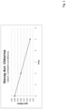
- Fig. 1 depicts the decay of a chlorine solution over time in dark ambient conditions. It can be seen that the chlorine in the solution decays from 340 parts per million (ppm) to 315 ppm over 5 days, which represents over a 7% reduction in the active chlorine present in the solution. The decay of chlorine can become even more significant as more time passes and when the solution is placed in environments that have extreme temperatures, UV exposure, etc., until the point when the solution is no longer able to act as a suitable disinfecting solution.
- Traditional vessel systems do not monitor a solution that has been placed into a vessel, and are unable to alert a user that the solution is no longer able to perform its function.
- Traditional vessel systems also have no accurate way to help ensure that the cleaning, disinfecting, etc. solution is always applied at a required quality level and quantity.
- the vessel can be a spray bottle, a squeeze bottle, a bucket, an applicator bottle or tube, a flask, or any other container in which the solution is stored prior to its application.
- the solution can include any type of cleaning solution, disinfectant solution, oxidizer solution, non-oxidizer solution, etc. known in the art.
- the solution is created by dilution of one or more product concentrates or an electrolysis process.
- the vessel systems described herein include an intelligent (or smart) vessel that is filled using a filling station, such as an ECA dispensing machine.
- a filling station such as an ECA dispensing machine.
- the vessel can be configured to communicate with the filling station such that the filling station is able to identify the vessel and ensure that the appropriate solution is added to the vessel.
- the filling station is also used to ensure that the vessel is empty prior to being filled to help ensure that a newly added solution is not degraded by any old solution remaining in the vessel.
- the filling station can also be used to test the concentration and quality of the chemical concentrate(s) and dilute(s) prior to their placement in the vessel and again after the solution is formed in the vessel.
- the vessel system may include a vessel that is filled with a hand mixed solution or a solution that is premixed at a factory.
- the vessel is configured to store information regarding the cleaning or disinfecting solution that is received from the filling station.
- the vessel is also configured to use a timer to monitor the length of time that the solution has been in the bottle. Once a predetermined amount of time (i.e. shelf life) has passed, the vessel can activate an alarm and/or indicator to alert the user that it is time to replace the solution.
- the predetermined amount of time can be based on the type of solution, the concentration of the solution, the intended use of the solution, and/or the environmental conditions to which the solution will be subjected.
- the vessel is also configured to periodically monitor the concentration of the solution and to alert the user if the concentration falls below a predetermined threshold.
- the concentration threshold can also be based on the type of solution, the concentration of the solution, the intended use of the solution, and/or the environmental conditions to which the solution will be subjected.
- the vessel can also include a motion sensor which can be used for the purposes of monitoring solution use and identifying the appropriate time to activate an alert/indicator for the user.
- Fig. 2 is a block diagram of a filling station 200 in accordance with an illustrative embodiment.
- the filling station 200 includes a processor 205, a memory 210, solution sensor(s) 215, one or more transceivers 220, a power source 225, one or more reservoirs 230, and an interface 235.
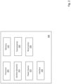
- Fig. 3 is a block diagram of a vessel 300 in accordance with an illustrative embodiment.
- the vessel 300 includes a processor 305, a memory 310, a solution indicator 315, solution sensor(s) 320, a transceiver 325, a power source 330, a timer 335, a motion sensor 340, a user interface 345, a vessel head 350, and a reservoir 355.
- the filling station 200 and the vessel 300 can include additional, fewer, and/or different components.
- the memory 210 of the filling station 200 can be any type of computer memory or storage known in the art.
- the memory 210 can be used to store vessel identifiers associated with specific vessels, a type of solution associated with each of the vessel identifiers, a shelf life for each type and/or concentration of solution, sensor data generated for a solution placed into a vessel, communication and other algorithms, etc.
- the processor 205 of the filling station 200 can be any type of single or multiple computer processor known in the art.
- the processor 205 can be used to implement any algorithms stored in the memory 210, to control the one or more transceivers 220 to communicate with a vessel, to control the solution sensor(s), to generate instructions and/or thresholds for the vessel, and to control other components of the filling station 200.
- the one or more transceivers 220 can be any type of receiver(s) and transmitter(s) known in the art, and can be used to allow the filling station 200 to communicate with a vessel and/or a user device.
- the one or more transceivers 220 are near-field communication (NFC) transceivers that are configured to transmit/receive data over a short distance using the NFC protocol.
- NFC near-field communication
- additional and/or different transceiver types may be incorporated into the filling station 200 such as Bluetooth ® , wi-fi, cellular, radio frequency (RF), etc.
- the power source 225 of the filling station 200 can be a standard electrical outlet, a battery, and/or any other type of charge storage/distribution components known in the art.
- the power source 225 is used to provide power to the processor 205 and other components of the filling station 200.
- the one or more reservoirs 230 of the filling station 200 are used to store a dilute, one or more chemicals that are mixed with the dilute, and/or a formed solution.
- the filling station 200 can be configured to generate solutions using electrochemical processes known in the art, such as electrolysis.
- the interface 235 of the filling station 200 can include a touchscreen display, a keyboard, one or more dispensing buttons, and/or any other components that allow a user to interact with the filling station 200.
- users can also interact with the filling station 200 through an application on a user device such as a smart phone, computer, etc.
- the one or more solution sensor(s) 215 can be one or more electrical sensors that are used to monitor temperature, conductivity, amperage resistance, and/or voltage of a solution.
- the solution sensor(s) 215 are used to determine characteristics of the components (e.g., cleaning/disinfection chemistry, water, and contaminants in the water which may affect the accuracy of the filling station sensors) which form the solution and the solution itself prior to its initial placement into a vessel.
- the filling station 200 is designed to only fill a vessel that is determined to be empty such that new solution is not degraded by any old solution remaining in the vessel.
- the types of measurements performed on a solution using the solution sensor(s) 215 can depend on the type of solution. For example, based on its composition, a cleaning solution is less likely to experience chemical degradation than a disinfecting solution. However, cleaning solutions are more likely to experience biological growth (e.g., bacteria) and contamination than a disinfecting solution. As a result, in one embodiment, a cleaning solution may be monitored solely based on a shelf life, which is a period of time during which the solution is expected to be effective for its intended use. Conversely, a disinfecting solution may be monitored to periodically determine one or more chemical concentrations in the solution to determine if the solution is still effective or if it should be replaced. In other embodiments, a cleaning solution and a disinfecting solution can both be subjected to shelf life monitoring and chemical concentration monitoring. A more detailed discussion of the solution monitoring processes is included below, along with several examples.
- the memory 310 of the vessel 300 which can be any type of computer memory or storage known in the art, can be used to store information such as a vessel identifier (ID), data regarding the type and content of the solution stored in the vessel, solution testing algorithms, shelf life data, communication algorithms, and/or any other relevant information that allows the vessel 300 to properly function.
- ID vessel identifier
- the memory 310 of the vessel 300 can be used to store information such as a vessel identifier (ID), data regarding the type and content of the solution stored in the vessel, solution testing algorithms, shelf life data, communication algorithms, and/or any other relevant information that allows the vessel 300 to properly function.
- the processor 305 can be any type of single or multiple computer processor known in the art.
- the processor 305 can be used to implement the algorithms stored in the memory 310, to control the transceiver 325 to communicate with a filling station or user device, to process data received from the solution sensor(s) 320 and the motion sensor 340, to control the solution indicator 315, etc.
- the transceiver 325 can be any type of transmitter and receiver known in the art.
- the transceiver 325 is a near-field communication (NFC) transceiver that is configured to transmit/receive over a short distance using the NFC protocol.
- NFC near-field communication
- additional and/or different transceiver types may be incorporated into the vessel 300, such as Bluetooth ® , wi-fi, cellular, radio frequency (RF), etc.
- the power source 330 of the vessel 300 can be a battery or any other type of portable charge storing component known in the art.
- the power source 330 can be used to provide power to all of the other components of the vessel 300.
- the power source 330 can be rechargeable such that a user is able to recharge the power source 330 at a filling station or a standard power outlet.
- the timer 335 is used to monitor the amount of time that a cleaning or disinfecting solution has been in the vessel 300.
- the timer 335 is reset when the solution is placed into the vessel 300.
- the timer 335 can be reset by the filling station used to fill the vessel 300, by the processor 305 of the vessel 300 in response to an instruction received from the filling station, or by a user of the vessel 300.
- the processor 305 can activate the solution indicator 315 such that the user is made aware that the solution needs to be replaced.
- the predetermined amount of time can be stored in the memory 310 and can be specific to the type of solution, the original concentration of the solution, the intended use of the solution, and/or the ambient conditions in which the solution is used/stored.
- the predetermined amount of time can be calculated using any procedures known in the art.
- the one or more solution sensor(s) 320 can include one or more electrical sensors that are used to monitor temperature, conductivity, amperage, resistance, and/or voltage such that the concentration of the cleaning or disinfection chemicals can be monitored in the solution.
- the vessel 300 can include the same type(s) of solution sensors as the filling station 200. Alternatively, the vessel 300 may include different solution sensors than the filling station 200.
- the one or more solutions sensor(s) 320 can be used to determine whether the vessel is empty as described herein. Use of the solution sensor(s) 320 to perform solution monitoring is also described in more detail in the examples included below.
- the solution indicator (or alarm) 315 can include one or more lights such as light-emitting diodes (LEDs), a display that includes text or symbols, one or more sound generating components, one or more vibration generating components, and/or any other components that can be used to alert a user of the status of a solution in the vessel 300.
- the solution indicator 315 can be in the form of a light that is green when the solution status is good and red when the solution status is bad. Alternatively, other colors may be used.
- the solution indicator 315 is controlled based on results of the monitoring performed using the one or more solution sensor(s) 320 and/or the status of the timer 335 used to monitor shelf life of the solution. Activation and use of the solution indicator 315 is described in more detail with reference to the examples below.
- the motion sensor 340 can include any type of movement sensing technology known in the art.
- the motion sensor 340 can be used to detect movement of the vessel 300, which should be indicative of the presence of a user.
- the motion sensor 340 can therefore be used to activate the solution indicator 315 while a user is present to help preserve the power source 330.
- the processor 305 can activate the solution indicator 315 (e.g., as a green light) to indicate that the solution in the vessel is still good.
- the processor 305 can activate the solution indicator 315 (e.g., as a red light) to indicate that the solution in the vessel is no longer usable and should be replaced.
- the solution indicator 315 can be activated for a predetermined amount of time after the movement is detected by the motion sensor 340, such as 10 seconds, 30 seconds, 1 minute, 2 minutes, 5 minutes, etc.
- the vessel 300 can be configured such that the solution indicator 315 is only activated in response to motion after a predetermined amount of time has passed since the last activation of the solution indicator 315 or the last movement detected by the motion sensor 340.
- the motion sensor 340 can detect motion, and the solution indicator 315 can be activated for a predetermined duration of time after the detected movement to inform the user of the solution status. The user may continue to periodically move the vessel 300 while using it over a period of 30 minutes.
- the processor 305 can ensure that the solution indicator 315 is only activated a single time during the 30 minutes that the vessel 300 is being used.
- the processor 305 can use a timer to ensure that an inactivity period has passed prior to re-activating the solution indicator 315.
- the inactivity period can be 10 minutes, 15 minutes, 1 hour, 2 hours, etc.
- the processor 305 can start a timer when the solution indicator 315 is activated to ensure that the solution indicator 315 is only activated once within a given time period such as 10 minutes, 15 minutes, 1 hour, 2 hours, etc.
- re-activation of the solution indicator 315 can be responsive to both expiration of the predetermined time period since the last activation and subsequent movement detected by the motion sensor 340.
- the motion sensor 340 can be used to monitor and/or track use of the vessel 300 to help ensure that a user is doing his/her job properly.
- the vessel 300 can store data regarding the time/duration of detection movement in the memory 310. An administrator can access the stored data to monitor use of the vessel 300 and to determine if the vessel 300 is being used at the appropriate time(s) and/or an appropriate number of times over a given time period.
- the vessel can also include a location tracking sensor that can determine the location of the vessel 300 throughout a day, week, etc.
- the location tracking sensor can be a global positioning system (GPS) sensor, a radio frequency (RF) sensor, a wi-fi tag, and/or any other location detecting sensor(s) known in the art.
- GPS global positioning system
- RF radio frequency
- wi-fi tag any other location detecting sensor(s) known in the art.
- location information regarding the vessel 300 can also be stored in the memory 310.
- the user interface 345 of the vessel 300 can include a display, one or more buttons, a keypad, and/or any other components that allow a user or administrator to interact with the vessel.
- the user interface 345 can allow the user to adjust default thresholds, reset the vessel 300, assign a vessel ID, program the vessel 300, etc.
- the user interface 345 can be remotely accessible through an app or other program on a user device such as a smartphone or computer.
- the app or other program can communicate with the vessel via the transceiver 325.
- the vessel 345 may be preprogrammed and may not include a user interface.
- the vessel head 350 of the vessel is used to apply the solution from the vessel 300 to a surface.
- the vessel head 350 can be a trigger sprayer, a pump sprayer, a squeeze hole, an applicator, and/or other dispensing mechanism known in the art.
- the vessel may be a type of container (e.g., a bucket) that does not include a vessel head.
- the reservoir 355 can be any type of receptacle that is able to hold the solution.
- the one or more solution sensor(s) 320 may be placed within the reservoir 355 such that one or more sensor electrodes are in contact with the solution for taking measurements.
- the one or more solution sensor(s) 215 of the filling station 200 and the one or more solution sensor(s) 320 of the vessel 300 can be electrical sensors that are used to test/monitor temperature, conductivity, amperage, voltage, and/or amperage at specific chemical reaction potentials (i.e., voltages) of a solution.
- the sensors can be used to perform voltammetry such as linear sweep voltammetry, staircase voltammetry, square wave voltammetry, cyclic voltammetry (i.e., a voltammetric method that can be used to determine diffusion coefficients and half cell reduction potentials), anodic stripping voltammetry (i.e., a quantitative, analytical method for trace analysis of metal cations in which an analyte is deposited (electroplated) onto the working electrode during a deposition step, and then oxidized during a stripping step at which time the current is measured), cathodic stripping voltammetry (i.e., a quantitative, analytical method for trace analysis of anions in which a positive potential is applied, oxidizing a mercury electrode and forming insoluble precipitates of the anions, and in which a negative potential then reduces (strips) the deposited film into solution), adsorptive stripping voltammetry (i.e., a quantitative, analytical method for trace
- voltammetry
- the vessel system can solely utilize a shelf life timer to determine whether a solution placed into a vessel is still usable.
- a shelf life timer may be appropriate for certain types of solutions such as cleaning solutions and non-oxidizer disinfecting solutions in which chemical decay, in and of itself, is not a major concern.
- Cleaning solutions are typically very dilute and include little or no preservative ingredients, which makes them susceptible to bacterial growth. Such bacterial growth can cause the solution to become unhygienic.
- Non-oxidizer disinfecting solutions are typically self-preserving and can have a relatively long shelf life.
- the shelf life can be solution specific and can be based on solution type, solution concentration, the environment in which the solution is used or stored, etc. In one embodiment, a standardized preservation test score for the solution can be used to determine the shelf life period.
- a user fills a vessel by removing the vessel head (if present) from the vessel and placing the vessel on a docking station or pad of the filling station.
- the filling station communicates with the vessel to determine a Vessel Identifier (ID) and Solution Type associated with the vessel.
- the filling station also uses a conductivity sensor within the vessel to determine whether the vessel is empty.
- the filling station can determine whether the vessel is empty based on a mass of the vessel and/or any other techniques.
- the filling station is configured to prevent the vessel from being filled if the vessel has old solution therein.
- the filling station can enable a product dispense button on the filling station.
- the user can press or otherwise activate the product dispense button to begin filling the vessel with solution.
- the filling station can reset the shelf life timer on the vessel.
- the filling station can also determine the shelf life for the solution and provide the shelf life to the vessel such that the vessel can activate the solution indicator (e.g., a red indicator light) to indicate that the solution should be replaced upon expiration of the shelf life.
- the shelf life can be specific to the type of solution being placed in the vessel and may be based on environmental conditions in which the vessel is expected to be stored or used.
- the solution indicator can also be activated for a period of time responsive to the filling of the vessel to indicate that the solution is in good condition (e.g., a green indicator light).
- the period of time can be 1 minute, 2 minutes, 5 minutes, etc.
- the vessel may be configured to activate the solution indicator for a short period of time responsive to detected movement of the vessel. If the timer indicates that the shelf life has not passed, the vessel solution indicator can indicate that the solution is in good condition, or still usable. If the timer indicates that the shelf life is expired, the solution indicator indicates that the solution is no longer usable. Responsive to an indication that the solution is no longer usable, the user should properly dispose of any remaining solution in the vessel and then begin the refill process as discussed above.
- the vessel system can monitor solution quality in real-time to determine whether the solution is still suitable for use.
- the real-time solution monitoring can be performed alone or in combination with a shelf life timer as discussed above.
- the real-time solution monitoring is performed for oxidizer disinfection solutions that have an active chemical (e.g., hypochlorite, hydrogen peroxide, etc.) that is known to decay over time.
- the chemical decay can be difficult to predict because it is affected by many factors that can be difficult to control/predict, such as temperature, UV light exposure, an amount of metal ion traces in the solution, the presence of organic matter in the solution, etc.
- the real-time solution monitoring can also be used to monitor a cleaning solution and/or a non-oxidizer disinfection solution.
- a first operation in performing real-time solution monitoring is to perform measurements on the water (or other liquid) that is used to form the solution.
- the water can be used as a dilute added to a chemical concentrate (or vice versa), or as part of an electrolysis process that is used to form the solution.
- the water may include minerals, metals, organic materials, etc. that can create a noise signal and affect the subsequent solution measurements, which are described below.
- the measurement performed on the water is a reference measurement that can be used to compensate for the noise signal during the subsequent measurements of the solution.
- the water is measured at/by the filling station prior to the introduction of any chemicals or other additives.
- the results of the water measurement can be stored at the filling station and also in the memory of the vessel such that the measurements can be used for setpoint (i.e., an active chemistry level threshold) determination and correction.
- a second operation in performing the real-time solution monitoring is to measure the water plus the chemical(s), etc. that have been introduced to the water to form the solution, either by dilution or an electrolysis process.
- the chemical introduced into the water can include both converted (e.g., hypochlorite) and unconverted (e.g., chloride) products.
- this second measurement is a reference measurement that also takes place at the filling station prior to placement of the solution into the vessel. The result of the measurement can be stored at the filling station and also in the memory of the vessel for use in setpoint determination and correction.
- the first and second reference measurements discussed above can also be used to monitor the quality of the electrolytic cell, in addition to key process parameters such as pH, conductivity, and oxidation reduction potential (ORP) to help ensure that the solution generation process is safely performed.
- the first and second reference measurements also enable solution concentration control during the dispensing process to help avoid product overdosing and underdosing.
- the first and second reference measurements can be used during manufacturing to monitor the quality of the solution production process.
- a third operation in performing the real-time solution monitoring is to conduct measurements directly after the solution has been placed into the vessel and also periodically (or randomly) over time.
- This series of third measurements can be performed at/by the vessel.
- the third measurements are used in conjunction with the above-discussed first and second reference measurements to determine the actual concentration level of the disinfectant in the solution.
- Each of the third measurements is compared to a threshold (or setpoint) which represents the lowest acceptable concentration (or other characteristic) for the disinfectant or other chemical.
- the threshold can be a specific concentration value, a value of a relative change in concentration relative to a starting concentration, a change in or specific value of conductivity, a change in or specific value of a voltammetry profile, a change in or specific value of a chronoamperometry profile, etc. If the vessel determines that the measured concentration is below the concentration threshold, the solution indicator is activated to inform the user that the solution should be replaced.
- the above-described first, second, and third measurements can be conductivity measurements, voltammetry measurements, and/or chronoamperometry measurements.
- the measurement techniques can be used alone or in combination with one another.
- the sensors used to conduct the measurements can be formed using screen printed electrode technology to enable measurements within the vessel.
- the sensor electrodes can be formed from gold, platinum, glassy carbon, and/or any other suitable materials known in the art.
- sensors can also be used to measure pH of the solution, to determine quality of an electrolytic cell used to generate the solution, to measure UV light exposure via spectrophotometry, etc.
- the first reference measurement can be a conductivity measurement of the water (or other liquid) in the filling station.
- the second reference measurement can be a conductivity measurement of the water and the chemical(s) introduced into the water at the filling station.
- the third measurements can be conductivity measurements of the solution in the vessel. During decay of the disinfectant chemical (e.g., from hypochlorite to chloride ions in the case of chlorine solutions), the conductivity of the solution changes. When a predetermined conductivity change has occurred or when a conductivity threshold has been exceeded, the vessel can activate the solution indicator to inform the user that the solution should be replaced.
- the conductivity measurements can be temperature compensated as known in the art.
- the conductivity measurements can be conducted using a temperature sensor, one or more conductivity sensors, one or more voltage sensors, one or more current sensors, and/or one or more resistance sensors.
- the first, second, and third measurements of the solution can be voltammetry measurements based on cyclic voltammetry (CV), linear sweep voltammetry (LSV), and/or step and pulse voltammetry (S&PV).
- the first measurement can be a CV, LSV, and/or S&PV profile that is compensated for both temperature and pH of the water, and that is determined by scanning the voltage range between the water decomposition potentials and beyond for the water.
- the second measurement can be a CV, LSV, and/or S&PV profile that is compensated for both temperature and pH of the water and introduced chemical(s) in either a reacted or unreacted state.
- the second measurement is performed by scanning the voltage range between the water decomposition potentials and beyond for the solution.
- the third measurements can similarly be temperature and pH compensated CV, LSV, and/or S&PV profile measurements of the solution in the vessel. Over time, the CV, LSV, and/or S&PV profile of the solution will change as the chemical in the solution degrades. When a predetermined profile change has occurred or when a profile threshold has been exceeded, the vessel can activate the solution indicator to inform the user that the solution should be replaced.
- the voltammetry measurements can be conducted using a temperature sensor, a pH meter, one or more conductivity sensors, one or more voltage sensors, one or more current sensors, and/or one or more resistance sensors as known in the art.
- the first, second, and third measurements of the solution can be based on chronamperometry (CA) or chronopotentiometry (CP).
- the first measurement can be a CA and/or CP profile that is compensated for temperature of the water, and that is determined by scanning the voltage range between the water decomposition potentials, including short chrono measurements at specific predefined potentials for the water.
- the second measurement can be a CA and/or CP profile that is compensated for temperature of the water and introduced chemical(s) in either a reacted or unreacted state. The second measurement is performed by scanning the voltage range between the water decomposition potentials, including short chrono measurements at specific predefined potentials for the water and added chemical(s).
- the third measurements can similarly be temperature compensated CA and/or CP profile measurements of the solution in the vessel. Over time, the CA or CP profile of the solution will change as the chemical in the solution degrades. When a predetermined profile change has occurred or when a profile threshold has been exceeded, the vessel can activate the solution indicator to inform the user that the solution should be replaced.
- the CA or CP measurements can be conducted using a temperature sensor, one or more conductivity sensors, one or more voltage sensors, one or more current sensors, one or more potentiometers, and/or one or more resistance sensors as known in the art.
- Fig. 4 depicts a filling station 400 in accordance with an illustrative embodiment.
- the filling station includes a first docking pad (or docking station) 405, a second docking pad 410, a third docking pad 415, and a fourth docking pad 420.
- a first docking pad (or docking station) 405 a second docking pad 410, a third docking pad 415, and a fourth docking pad 420.
- fewer or additional docking pads may be used.
- Each of the docking pads is configured to receive a vessel that is to be filled.
- the docking pads can include one or more ports that allow a vessel battery to be charged and/or information to be transferred between the filling station 400 and a vessel.
- the docking pads may just be designated areas in which a vessel can be placed for a fill operation.
- the fill station is able to wirelessly communicate with a vessel that is positioned at one of the docking pads, as described herein.
- each of the fill nozzles can be associated with a particular solution such that the fill nozzle only dispenses the particular solution and no others.
- each of the fill nozzles may be configured to dispense one of a plurality of solutions.
- Each of the fill nozzles is associated with an interface.
- the first fill nozzle 425 is associated with a first interface 445, etc.
- the first interface 445 includes a display 450 and a dispense button 455.
- the second, third, and further interfaces 460, 465, and 470 can similarly include a display and dispense button.
- the display 450 can be an electronic display, a sticker, a plate, etc. that provides information to a user such as the type of solution associated with that docking pad or instructions. For example, if the filling station determines that the vessel placed on the docking pad 405 is not empty, the display 450 may instruct the user to empty the vessel completely prior to attempting a fill operation.
- the display 450 may also indicate the type of solution and/or characteristics of the solution that is to be placed into the vessel.
- the display 450 can include a touchscreen, keypad, or other mechanism through which a user can enter information into the filling station.
- the filling station 400 may not include any displays.
- the dispense button 450 can be pressed by the user to commence the fill operation.
- the display 450 may be incorporated into a face of the dispense button 450.
- the dispense button 450 may light up when the filling station 400 is ready for a user to commence the fill operation, such as in response to a determination that the vessel is empty.
- Fig. 5 depicts a vessel in the form of a dispenser 500 in accordance with an illustrative embodiment.
- the dispenser 500 is in the form of a spray bottle and includes a solution 505 in a reservoir that can be dispensed through a dispensing head 510, which is in the form of a trigger activated spray nozzle.
- the dispenser 500 can be in any other form and can include a different type of dispensing head.
- the dispenser 500 also includes an electronics unit 515 that has an incorporated indicator light 520.
- the electronics unit 515 can include dispenser components such as a processor, a memory, one or more solution sensors, a transceiver, a power source, a timer, a motion sensor, etc.
- the indicator light 520 can be a solution indicator that is used to inform a user of the status of the solution 505.
- the indicator light 520 can display a green light if the solution 505 is still good and a red light if the solution 505 should be replaced.
- any other type of indicator system may be used.
- the electronics unit 515 is depicted at a bottom of the dispenser 500, in alternative embodiments the electronics unit 515 may be positioned in the dispensing head 510 or elsewhere within the dispenser 500.
- the dispenser 500 can be configured to prevent use of the solution 505 if the dispenser determines that the solution should not be used due to expiration, degradation, etc.
- the dispenser 500 can include a solenoid or other mechanical component that prevents actuation of the dispensing head 510 or the pump/tube connected to the dispensing head 510.
- the electronics unit 515 of the dispenser can activate the solenoid to mechanically prevent further use of the solution.
- the solenoid can activate a mechanical trigger stop, a mechanical component to block the dispensing tube, a pump block, etc. so that the user is physically unable to dispense the solution.
- the dispenser 500 can remain unusable until the dispenser is filled with fresh solution from a filling station.
- the processor of the dispenser 500 can control the solenoid or other mechanical component to unlock/activate dispenser responsive to a signal from the filling station indicating that the dispenser has been filled with fresh solution.
- the pump of the dispenser can be an electronic pump that the user activates by pressing a button or other control.
- the electronics unit 515 of the dispenser 500 can deactivate the electronic pump so that it cannot be used to dispense the solution.
- the electronic pump of the dispenser can remain deactivated until fresh solution is placed in the dispenser.
- the dispenser upon placement of the fresh solution in the dispenser, the dispenser will automatically reactivate itself.
- an administrator may also be able to override the deactivation through an interface of the dispenser and/or through a filling station used to fill the dispenser.
- the dispensers described herein can also include one or more temperature sensors that can be used to help monitor the solution.
- the one or more temperature sensors can monitor the temperature of the solution, which can become elevated if the dispenser is left out in the sun or in an area (e.g., a boiler room) with elevated temperatures.
- the solution can be found unsuitable for use if the monitored temperature ever exceeds a temperature threshold, which can vary depending on the solution.
- the temperature threshold may be 90° F, 100° F, 110° F, etc.
- the solution can also be found unsuitable for use if the temperature exceeds a temperature threshold for a designated amount of time.
- the solution may be considered bad if the temperature of the solution exceeds 105° F for more than 15 minutes.
- the specific combination of temperature and time can vary depending on the type of solution.
- the dispensers described herein can also include one or more light sensors that can be used to help monitor the solution.
- the one or more light sensors can monitor exposure of the solution to ultraviolet rays, and can specifically measure light wavelength and/or intensity (e.g., milliwatts per square centimeter).
- the solution can be found unsuitable for use if the amount of UV radiation exposure exceeds a threshold, which can vary depending on the solution. For example, the solution may be designated unusable if the intensity of UV radiation ever exceeds a given threshold value. Alternatively, the solution may be designated unusable if the intensity of UV radiation exceeds a given threshold value for a given amount of time.
- Both the temperature and light sensor(s) can be used in combination with one another to evaluate the solution and/or in combination with other solution monitoring techniques described herein.
- the dispenser system can include a timer, which can have multiple different functions depending on the embodiment.
- the timer can also be used to determine an amount of time that the dispenser was in actual use in between fill ups.
- the processor of the dispenser can use the timer to generate timestamps each time a user starts and stops using the dispenser to dispense solution. By analyzing the time stamps, the processor can then determine the total amount of time that the dispenser was in use (i.e., the frequency of use) in between fill ups.
- the timer can also be used in conjunction with the motion sensor to determine the amount of time that the dispenser was in motion (e.g., being pushed on a cleaning cart, in actual use, etc.) versus the amount of time that the dispenser was stationary in between fill ups. These features can be used to help ensure that employees are actually using the solution and properly doing their jobs.
- Fig. 6 is a flow diagram depicting operations performed by a vessel system in accordance with an illustrative embodiment. In alternative embodiments, fewer, additional, and/or different operations may be performed. Also, the use of a flow diagram is not meant to be limiting with respect to the order of operations performed.
- a filling station receives vessel information.
- the vessel information can be received upon placement of the vessel on or near the filling station by a user and via communication between a transceiver of the vessel and a transceiver of the filling station.
- the vessel information can include a vessel ID and/or information regarding a type of solution that is to be placed into the vessel.
- the filling station determines that the vessel is empty.
- the determination that the vessel is empty can be based on a conductivity measurement and/or any other type of measurements to determine absence of the solution.
- the filling station can utilize one or more sensors within the vessel to make the determination that the vessel is empty. If it is determined that the vessel is not empty, the filling station can instruct the user to completely empty the vessel prior to attempting a fill operation.
- the filling station conducts reference measurements on the water (or other liquid) that is used to form the solution.
- the filling station conducts reference measurements of the water and chemical(s) that form the solution prior to placement of the solution into the vessel.
- the reference measurements of operations 610 and 615 can be conducted as conductivity measurements, voltammetry measurements, and/or chronoamperometry measurements as described herein.
- the reference measurements are transferred to the vessel for use in determining a shelf life for the solution and/or one or more thresholds (or setpoints) related to solution concentration or other characteristic.
- the filling station can determine the shelf life for the solution and/or the one or more thresholds and transfer that information directly to the vessel.
- the operations 610-620 may not be performed.
- the filling station enables the product dispense button on the filling station such that the user can commence the dispensing of the solution into the vessel.
- the filling station can activate a light or other indicator to inform the user that the dispense button has been activated.
- the filling station dispenses the solution into the vessel responsive to button activation.
- the timer on the vessel is activated.
- the timer is configured to expire when the determined shelf life for the solution has passed.
- the shelf life can be 1 day, 2 days, 1 week, 2 weeks, 1 month, etc. depending on the solution and its characteristics.
- the vessel conducts initial measurements of the solution in the vessel.
- the initial measurements can be performed while the vessel is docked at the filling station such that the measurement data can be transferred to the filling station.
- the initial measurements can be conducted after the vessel is removed from the filling station.
- the initial measurements can be conducted as conductivity measurements, voltammetry measurements, and/or chronoamperometry measurements as described herein.
- the vessel determines a shelf life and/or measurement thresholds for the solution based on the first and second reference measurements, the initial measurement of the solution in the vessel, the solution type, environmental information regarding where the solution is to be used/stored, etc.
- the shelf life and/or measurement thresholds may be determined prior to commencement of the timer on the vessel.
- the shelf life and/or measurement thresholds can be determined using any techniques known in the art.
- the vessel conducts subsequent measurements of the solution in the vessel.
- the subsequent measurements can be conducted as conductivity measurements, voltammetry measurements, and/or chronoamperometry measurements, and can be repetitions of the initial measurement(s) made in the operation 640.
- the subsequent measurements can be conducted on a periodic basis such as once every hour, once every day, once a week, etc. depending on the solution and its characteristics and/or environmental exposure.
- the operations 640 and 650 may not be performed.
- the vessel determines whether a solution threshold has been exceeded. The determination can be based on the subsequent measurements performed in the operation 650. If it is determined that the solution threshold has not been exceeded, the vessel determines whether the timer has expired in an operation 660. If it is determined that the solution threshold has not been exceeded and that the timer has not expired, the vessel activates a 'good' solution indicator responsive to detected vessel motion in an operation 665.
- the good solution indicator can, as an example, be a green light, a textual message, or any other positive indicator. The vessel continues to perform operations 650-665 until either the solution threshold is exceeded or the timer expires.
- the vessel determines in the operation 655 that the solution threshold has been exceeded or that the timer has expired in the operation 660, the vessel activates a 'bad' solution indicator in an operation 670.
- the bad solution indicator can be a red light, a textual message, or any other negative indicator.
Landscapes
- Chemical & Material Sciences (AREA)
- Health & Medical Sciences (AREA)
- Analytical Chemistry (AREA)
- Chemical Kinetics & Catalysis (AREA)
- Physics & Mathematics (AREA)
- General Health & Medical Sciences (AREA)
- General Physics & Mathematics (AREA)
- Life Sciences & Earth Sciences (AREA)
- Clinical Laboratory Science (AREA)
- Electrochemistry (AREA)
- Hematology (AREA)
- Biochemistry (AREA)
- Immunology (AREA)
- Pathology (AREA)
- Apparatus For Disinfection Or Sterilisation (AREA)
- Investigating Or Analyzing Materials By The Use Of Electric Means (AREA)
- Details Of Rigid Or Semi-Rigid Containers (AREA)
Claims (15)
- Behälter (300), das Folgende umfassend:einen Speicher (310), der so konfiguriert ist, dass er eine Behälterkennung speichert; undeinen Behälter-Prozessor (305), der operativ mit dem Speicher verbunden ist, wobei der Behälter-Prozessor konfiguriert ist, um:einen Timer (335) für die Haltbarkeitsdauer einer in den Behälter eingebrachten Reinigungs- oder Desinfektionslösung auszulösen;in regelmäßigen Abständen eine Messung der Konzentration der Lösung mit einem oder mehreren Sensoren (320) im Behälter durchzuführen;die Messung mit einer minimalen chemischen Konzentrationsschwelle für die Lösung zu vergleichen; undeine Lösungskennung (315) zu aktivieren, um anzuzeigen, dass die Lösung in Reaktion auf eine zeitliche Bestimmung, dass die Haltbarkeitsdauer abgelaufen ist, oder eine quantitative oder qualitative Bestimmung, dass die Messung den Schwellenwert der minimalen chemischen Konzentration überschreitet, verworfen werden muss.
- Behälter (300) nach Anspruch 1, der ferner einen Behälter-Transceiver (325) umfasst, um mit einer Abfüllstation (200) zu kommunizieren, wobei der Behälter-Transceiver betriebsmäßig mit dem Behälter-Prozessor gekoppelt ist, der so konfiguriert ist, dass er die Behälterkennung an die Abfüllstation übermittelt.
- Behälter (300) nach Anspruch 1, der ferner einen Behälter-Transceiver (325) umfasst, der operativ mit dem Behälter-Prozessor gekoppelt ist, wobei der Behälter-Transceiver konfiguriert ist, um Referenzmessdaten bezüglich Referenzmessungen zu empfangen, die von einer Abfüllstation (200) durchgeführt wurden.
- Behälter (300) nach Anspruch 3, wobei der Behälter-Prozessor ferner konfiguriert ist, um die Haltbarkeitsdauer für die Lösung zumindest teilweise auf der Grundlage der Referenzmessdaten zu bestimmen.
- Behälter (300) nach Anspruch 3, wobei der Behälter-Prozessor (305) ferner konfiguriert ist, um den Schwellenwert für die minimale chemische Konzentration der Lösung zumindest teilweise auf der Grundlage der Referenzmessdaten zu bestimmen.
- Behälter (300) nach Anspruch 3, wobei die Referenzmessdaten eine Messung umfassen, die an Wasser durchgeführt wurde, das zur Bildung der Lösung verwendet wird.
- Behälter (300) nach Anspruch 3, wobei die Referenzmessdaten eine Messung umfassen, die an der Lösung vor dem Einfüllen der Lösung in den Behälter (300) durchgeführt wurde.
- Behälter (300) nach Anspruch 1, der ferner einen Bewegungssensor (340) umfasst, der operativ mit dem Behälter-Prozessor gekoppelt ist, wobei die Aktivierung der Lösungskennung (315) auf die vom Bewegungssensor (340) erfasste Bewegung des Behälters (300) reagiert.
- Behälter (300) nach Anspruch 1, der ferner einen Bewegungssensor (340) umfasst, der operativ mit dem Behälter-Prozessor (305) gekoppelt ist, wobei der Behälter-Prozessor konfiguriert ist, um die Lösungskennung (315) zu aktivieren, um anzuzeigen, dass die Lösung noch verwendbar ist, als Reaktion auf die Feststellung, dass die Haltbarkeitsdauer nicht abgelaufen ist, als Reaktion auf die Feststellung, dass die Messung den Schwellenwert nicht überschreitet, und als Reaktion auf die von dem Bewegungssensor (340) erfasste Bewegung.
- Behältersystem, das Folgendes umfasst:eine Abfüllstation (200) und einen Behälter (300) nach Anspruch 1,die Abfüllstation (200) umfassend:einen Abfüllstation-Transceiver (220), der konfiguriert ist, um die Behälterkennung von Behälter (300) zu empfangen, undeinen Abfüllstation-Prozessor (205), der operativ mit dem Abfüllstation-Transceiver (220) gekoppelt ist, wobei der Abfüllstation-Prozessor konfiguriert ist, um:eine erste Referenzmessung des zur Bildung einer Lösung verwendeten Wassers mit Hilfe eines oder mehrerer Abfüllstation-Sensoren (215) durchzuführen;eine zweite Referenzmessung an der Lösung vor dem Einfüllen der Lösung in den Behälter mit Hilfe des einen oder der mehreren Abfüllstation-Sensoren (215) durchzuführen;den Abfüllstation-Transceiver (220) zu veranlassen, Daten bezüglich der ersten Referenzmessung und der zweiten Referenzmessung an den Behälter (300) zu übermitteln; undeine Abfülldüse (425, 430, 435, 440) der Abfüllstation (200) zu veranlassen, die Lösung in den Behälter abzugeben; undwobei der Behälter (300) weiterhin umfasst:
einen Behälter-Transceiver (325), der konfiguriert ist, um die Behälterkennung an die Abfüllstation (200) zu senden und die Daten bezüglich der ersten Referenzmessung und der zweiten Referenzmessung zu empfangen. - Behältersystem nach Anspruch 10, wobei der Behälter-Prozessor (305) ferner konfiguriert ist, um die Haltbarkeitsdauer zumindest teilweise auf der Grundlage der Daten bezüglich der ersten Referenzmessung und der zweiten Referenzmessung zu bestimmen.
- Behältersystem nach Anspruch 10, wobei der Behälter-Prozessor (305) ferner konfiguriert ist, um den Schwellenwert zumindest teilweise auf der Grundlage der Daten bezüglich der ersten Referenzmessung und der zweiten Referenzmessung zu bestimmen.
- Behältersystem nach Anspruch 10, wobei der Abfüllstation-Prozessor (205) bewirkt, dass die Abfülldüsen (425, 430, 435, 440) der Abfüllstation (200) die Lösung in den Behälter abgeben, wenn festgestellt wird, dass der Behälter (300) leer ist.
- Behältersystem nach Anspruch 10, der ferner einen Bewegungssensor (340) umfasst, der operativ mit dem Behälterprozessor (305) gekoppelt ist, wobei die Aktivierung des Lösungskennzeichners (315) auf die vom Bewegungssensor (340) erfasste Bewegung des Behälters reagiert.
- Behältersystem nach Anspruch 14, wobei der Behälter-Prozessor (305) konfiguriert ist, um die Lösungskennung (315) zu aktivieren, um anzuzeigen, dass die Lösung noch verwendbar ist, als Reaktion auf die Feststellung, dass die Haltbarkeitsdauer nicht abgelaufen ist, als Reaktion auf die Feststellung, dass die Messung den Schwellenwert nicht überschreitet, und als Reaktion auf die vom Bewegungssensor (340) erfasste Bewegung.
Applications Claiming Priority (2)
| Application Number | Priority Date | Filing Date | Title |
|---|---|---|---|
| US201862662960P | 2018-04-26 | 2018-04-26 | |
| PCT/US2019/029095 WO2019210048A1 (en) | 2018-04-26 | 2019-04-25 | Smart vessel system |
Publications (3)
| Publication Number | Publication Date |
|---|---|
| EP3784396A1 EP3784396A1 (de) | 2021-03-03 |
| EP3784396A4 EP3784396A4 (de) | 2021-06-23 |
| EP3784396B1 true EP3784396B1 (de) | 2024-10-02 |
Family
ID=68293580
Family Applications (1)
| Application Number | Title | Priority Date | Filing Date |
|---|---|---|---|
| EP19792428.5A Active EP3784396B1 (de) | 2018-04-26 | 2019-04-25 | Intelligentes behältersystem |
Country Status (4)
| Country | Link |
|---|---|
| US (2) | US11959867B2 (de) |
| EP (1) | EP3784396B1 (de) |
| CN (1) | CN112368078B (de) |
| WO (1) | WO2019210048A1 (de) |
Families Citing this family (2)
| Publication number | Priority date | Publication date | Assignee | Title |
|---|---|---|---|---|
| US20240361169A1 (en) * | 2021-06-01 | 2024-10-31 | Smart Hydration Limited | Hydration monitors and systems |
| CN115841127A (zh) * | 2022-10-31 | 2023-03-24 | 宁德时代新能源科技股份有限公司 | 电解液加注控制方法、设备及存储介质 |
Citations (1)
| Publication number | Priority date | Publication date | Assignee | Title |
|---|---|---|---|---|
| EP2967506B1 (de) * | 2013-03-15 | 2020-04-29 | Becton, Dickinson and Company | Intelligenter adapter für infusionsvorrichtungen |
Family Cites Families (38)
| Publication number | Priority date | Publication date | Assignee | Title |
|---|---|---|---|---|
| US5802015A (en) * | 1997-05-05 | 1998-09-01 | Rothschild Technology, L.L.C. | Intelligent label |
| US5922606A (en) * | 1997-09-16 | 1999-07-13 | Nalco Chemical Company | Fluorometric method for increasing the efficiency of the rinsing and water recovery process in the manufacture of semiconductor chips |
| US6843414B2 (en) * | 2001-04-02 | 2005-01-18 | Honeywell International Inc. | Smart container for bulk delivery |
| US7008523B2 (en) | 2001-07-16 | 2006-03-07 | Miox Corporation | Electrolytic cell for surface and point of use disinfection |
| US6595250B1 (en) * | 2002-02-28 | 2003-07-22 | Ideal Manufacturing Sales Corp. | Mobile fluid product filling system with fast setup |
| US7009519B2 (en) | 2002-11-21 | 2006-03-07 | S.C. Johnson & Sons, Inc. | Product dispensing controlled by RFID tags |
| AU2005246404A1 (en) * | 2004-05-21 | 2005-12-01 | Caliper Life Sciences, Inc. | Automated system for handling microfluidic devices |
| US8061562B2 (en) | 2004-10-12 | 2011-11-22 | S.C. Johnson & Son, Inc. | Compact spray device |
| US7424399B2 (en) | 2005-06-10 | 2008-09-09 | Ge Analytical Instruments, Inc. | Systems and methods for fluid quality sensing, data sharing and data visualization |
| CN101416048B (zh) * | 2006-01-12 | 2013-10-02 | 迈克罗拉布诊断有限公司 | 新仪器系统和方法 |
| GB0608829D0 (en) * | 2006-05-04 | 2006-06-14 | Husheer Shamus L G | In-situ measurement of physical parameters |
| GB2439307A (en) | 2006-06-23 | 2007-12-27 | Autonumis Ltd | Drink dispensing apparatus |
| US7900658B2 (en) | 2006-10-20 | 2011-03-08 | Fht, Inc. | Automated drug preparation apparatus including drug vial handling, venting, cannula positioning functionality |
| WO2008131389A1 (en) | 2007-04-22 | 2008-10-30 | Woody America Llc | Apparatus and methods for dispensing solutions |
| WO2008157801A2 (en) * | 2007-06-21 | 2008-12-24 | Gen-Probe Incorporated | Instrument and receptacles for performing processes |
| US8002898B2 (en) * | 2007-12-19 | 2011-08-23 | Diversey, Inc. | Material delivery systems and methods |
| CN202148181U (zh) | 2008-04-03 | 2012-02-22 | 乔治·扎布卢多夫斯基-尼鲁贝 | 可再装填容器及其中的散装产品供给和收费系统以及分发散装产品的散装产品分发装置 |
| JP5744762B2 (ja) | 2009-03-02 | 2015-07-08 | ディバーシー・インコーポレーテッド | 衛生状態監視管理システム及び方法 |
| US9051163B2 (en) | 2009-10-06 | 2015-06-09 | Ecolab Inc. | Automatic calibration of chemical product dispense systems |
| NL2004720C2 (nl) | 2010-05-14 | 2011-11-15 | Watter Holding B V | Inrichting voor het produceren van een electrochemisch geactiveerde oplossing middels een electrolyseproces. |
| CA2717631A1 (en) * | 2010-10-14 | 2012-04-14 | Anton Sabeta | Method and system for contact lens care and compliance |
| US8752732B2 (en) * | 2011-02-01 | 2014-06-17 | Sakura Finetek U.S.A., Inc. | Fluid dispensing system |
| US8550288B2 (en) * | 2011-10-19 | 2013-10-08 | Scott & Scott Enterprises, Llc | Beverage container with electronic image display |
| EP2909362B1 (de) | 2012-10-16 | 2017-12-06 | Geneon Technologies LLC | Elektrochemische aktivierung von wasser |
| WO2014102556A1 (en) | 2012-12-27 | 2014-07-03 | Ideapool Kft. | Container with an indicating device |
| WO2014204857A1 (en) * | 2013-06-17 | 2014-12-24 | Prime ITS | Material tracking system |
| US20170022045A1 (en) | 2013-11-25 | 2017-01-26 | Lorna G. Ray | System and method for dispensing product into refillable containers |
| US10619533B2 (en) * | 2014-05-21 | 2020-04-14 | Castrol Limited | Fluid system and method |
| CN106687039B (zh) * | 2014-07-17 | 2020-06-19 | 贝克顿·迪金森公司 | 生物样品容纳系统和标签 |
| US10029269B2 (en) | 2014-12-30 | 2018-07-24 | Gojo Industries, Inc. | Dispensing device |
| JP2018507103A (ja) * | 2015-02-06 | 2018-03-15 | ラブマインズ リミテッド | 自動化溶液ディスペンサ |
| CN106031698A (zh) * | 2015-03-16 | 2016-10-19 | 山东麦格信息技术有限公司 | 智能奶瓶 |
| US9563194B2 (en) * | 2015-05-04 | 2017-02-07 | Bby Solutions, Inc. | Random-access robotic inventory dispensary: replenishment and purge |
| EP3349716B1 (de) | 2015-09-14 | 2019-02-13 | Koninklijke Philips N.V. | Zuführsystem für ein kind und verfahren zur nutzung des systems |
| CN105080205B (zh) * | 2015-09-17 | 2018-03-06 | 北京金山安全软件有限公司 | 净化器滤网过期提示方法和装置及净化器 |
| US10589910B2 (en) | 2015-12-08 | 2020-03-17 | Honeywell Federal Manufacturing & Technologies, Llc | Container with expiration date alarm |
| US10588992B2 (en) * | 2016-04-22 | 2020-03-17 | Watertech Holdings Llc | Aerosol device |
| GB2550167A (en) * | 2016-05-11 | 2017-11-15 | Packaging Innovation Ltd | A liquid dispensing system |
-
2019
- 2019-04-25 EP EP19792428.5A patent/EP3784396B1/de active Active
- 2019-04-25 WO PCT/US2019/029095 patent/WO2019210048A1/en not_active Ceased
- 2019-04-25 CN CN201980043315.5A patent/CN112368078B/zh active Active
- 2019-04-25 US US17/049,389 patent/US11959867B2/en active Active
-
2024
- 2024-04-15 US US18/635,361 patent/US20240255455A1/en active Pending
Patent Citations (1)
| Publication number | Priority date | Publication date | Assignee | Title |
|---|---|---|---|---|
| EP2967506B1 (de) * | 2013-03-15 | 2020-04-29 | Becton, Dickinson and Company | Intelligenter adapter für infusionsvorrichtungen |
Also Published As
| Publication number | Publication date |
|---|---|
| EP3784396A4 (de) | 2021-06-23 |
| WO2019210048A1 (en) | 2019-10-31 |
| EP3784396A1 (de) | 2021-03-03 |
| US20210255129A1 (en) | 2021-08-19 |
| CN112368078A (zh) | 2021-02-12 |
| US20240255455A1 (en) | 2024-08-01 |
| US11959867B2 (en) | 2024-04-16 |
| CN112368078B (zh) | 2023-07-14 |
Similar Documents
| Publication | Publication Date | Title |
|---|---|---|
| US20240255455A1 (en) | Vessel for smart vessel system | |
| US11913903B1 (en) | Systems and methods for testing and measuring compounds | |
| US8999261B2 (en) | Device for hand disinfection | |
| US8662782B2 (en) | Surface cleaning device with a bleach generator | |
| US10295492B2 (en) | Electrochemical sensor and method of using same | |
| US12292402B2 (en) | Monitor and indicator system | |
| US20210069361A1 (en) | Disinfection method using a disinfection agent formed in situ by reaction of h2o2 and no2- | |
| US9404878B2 (en) | Systems and methods for detecting an H2O2 level in a cold aseptic filling system that uses a peracetic acid cleaning solution | |
| EP4320414A1 (de) | Verfahren und vorrichtung zur produktinventarkontrolle und leistungsoptimierung | |
| US8062499B2 (en) | Charge movement detector for electrochemically activated liquids | |
| JP2011218001A (ja) | ハンドウォッシャー | |
| EP4634653A1 (de) | Überwachungs- und anzeigesystem | |
| WO2019036586A1 (en) | Solution concentration sensing devices | |
| JP4950547B2 (ja) | 微酸性水生成装置 | |
| KR20130076174A (ko) | 전기분해 제어방법 및 이를 이용하는 살균수기 | |
| US12070051B1 (en) | Aqueous ozone disinfection system | |
| JPH10253584A (ja) | 残留ハロゲン濃度の評価方法及び評価機構 | |
| CN107328822B (zh) | 土壤酸碱度的监测方法及其装置 | |
| CN118225992A (zh) | 在静止测量点处校准电流型传感器的方法和电流型传感器的原位校准的设备 | |
| KR20220094566A (ko) | 휴대용 고농도 수소수 생성 장치 및 그 방법 | |
| KR20160008683A (ko) | 소형 전해수 생성장치 | |
| MXPA00007224A (en) | Automatic command and control of cleansing baths by means of alkalinity regulation |
Legal Events
| Date | Code | Title | Description |
|---|---|---|---|
| STAA | Information on the status of an ep patent application or granted ep patent |
Free format text: STATUS: THE INTERNATIONAL PUBLICATION HAS BEEN MADE |
|
| PUAI | Public reference made under article 153(3) epc to a published international application that has entered the european phase |
Free format text: ORIGINAL CODE: 0009012 |
|
| STAA | Information on the status of an ep patent application or granted ep patent |
Free format text: STATUS: REQUEST FOR EXAMINATION WAS MADE |
|
| 17P | Request for examination filed |
Effective date: 20201106 |
|
| AK | Designated contracting states |
Kind code of ref document: A1 Designated state(s): AL AT BE BG CH CY CZ DE DK EE ES FI FR GB GR HR HU IE IS IT LI LT LU LV MC MK MT NL NO PL PT RO RS SE SI SK SM TR |
|
| AX | Request for extension of the european patent |
Extension state: BA ME |
|
| REG | Reference to a national code |
Ref country code: DE Ref legal event code: R079 Free format text: PREVIOUS MAIN CLASS: B01L0003000000 Ipc: B05B0012000000 Ref country code: DE Ref legal event code: R079 Ref document number: 602019059766 Country of ref document: DE Free format text: PREVIOUS MAIN CLASS: B01L0003000000 Ipc: B05B0012000000 |
|
| A4 | Supplementary search report drawn up and despatched |
Effective date: 20210521 |
|
| RIC1 | Information provided on ipc code assigned before grant |
Ipc: B05B 12/00 20180101AFI20210517BHEP Ipc: A61L 2/18 20060101ALN20210517BHEP Ipc: A61L 2/22 20060101ALN20210517BHEP Ipc: B05B 11/00 20060101ALN20210517BHEP Ipc: B65D 83/56 20060101ALN20210517BHEP Ipc: G08B 21/24 20060101ALN20210517BHEP |
|
| DAV | Request for validation of the european patent (deleted) | ||
| DAX | Request for extension of the european patent (deleted) | ||
| STAA | Information on the status of an ep patent application or granted ep patent |
Free format text: STATUS: EXAMINATION IS IN PROGRESS |
|
| 17Q | First examination report despatched |
Effective date: 20230322 |
|
| GRAP | Despatch of communication of intention to grant a patent |
Free format text: ORIGINAL CODE: EPIDOSNIGR1 |
|
| STAA | Information on the status of an ep patent application or granted ep patent |
Free format text: STATUS: GRANT OF PATENT IS INTENDED |
|
| RIC1 | Information provided on ipc code assigned before grant |
Ipc: G08B 21/24 20060101ALN20240612BHEP Ipc: B65D 83/56 20060101ALN20240612BHEP Ipc: B05B 11/00 20060101ALN20240612BHEP Ipc: A61L 2/22 20060101ALN20240612BHEP Ipc: A61L 2/18 20060101ALN20240612BHEP Ipc: B05B 12/00 20180101AFI20240612BHEP |
|
| INTG | Intention to grant announced |
Effective date: 20240627 |
|
| RIC1 | Information provided on ipc code assigned before grant |
Ipc: G08B 21/24 20060101ALN20240619BHEP Ipc: B65D 83/56 20060101ALN20240619BHEP Ipc: B05B 11/00 20060101ALN20240619BHEP Ipc: A61L 2/22 20060101ALN20240619BHEP Ipc: A61L 2/18 20060101ALN20240619BHEP Ipc: B05B 12/00 20180101AFI20240619BHEP |
|
| GRAS | Grant fee paid |
Free format text: ORIGINAL CODE: EPIDOSNIGR3 |
|
| GRAA | (expected) grant |
Free format text: ORIGINAL CODE: 0009210 |
|
| STAA | Information on the status of an ep patent application or granted ep patent |
Free format text: STATUS: THE PATENT HAS BEEN GRANTED |
|
| AK | Designated contracting states |
Kind code of ref document: B1 Designated state(s): AL AT BE BG CH CY CZ DE DK EE ES FI FR GB GR HR HU IE IS IT LI LT LU LV MC MK MT NL NO PL PT RO RS SE SI SK SM TR |
|
| REG | Reference to a national code |
Ref country code: GB Ref legal event code: FG4D |
|
| REG | Reference to a national code |
Ref country code: CH Ref legal event code: EP |
|
| REG | Reference to a national code |
Ref country code: IE Ref legal event code: FG4D |
|
| REG | Reference to a national code |
Ref country code: DE Ref legal event code: R096 Ref document number: 602019059766 Country of ref document: DE |
|
| REG | Reference to a national code |
Ref country code: SE Ref legal event code: TRGR |
|
| P01 | Opt-out of the competence of the unified patent court (upc) registered |
Free format text: CASE NUMBER: APP_61769/2024 Effective date: 20241119 |
|
| REG | Reference to a national code |
Ref country code: LT Ref legal event code: MG9D |
|
| REG | Reference to a national code |
Ref country code: NL Ref legal event code: MP Effective date: 20241002 |
|
| REG | Reference to a national code |
Ref country code: AT Ref legal event code: MK05 Ref document number: 1728091 Country of ref document: AT Kind code of ref document: T Effective date: 20241002 |
|
| PG25 | Lapsed in a contracting state [announced via postgrant information from national office to epo] |
Ref country code: NL Free format text: LAPSE BECAUSE OF FAILURE TO SUBMIT A TRANSLATION OF THE DESCRIPTION OR TO PAY THE FEE WITHIN THE PRESCRIBED TIME-LIMIT Effective date: 20241002 |
|
| PG25 | Lapsed in a contracting state [announced via postgrant information from national office to epo] |
Ref country code: NL Free format text: LAPSE BECAUSE OF FAILURE TO SUBMIT A TRANSLATION OF THE DESCRIPTION OR TO PAY THE FEE WITHIN THE PRESCRIBED TIME-LIMIT Effective date: 20241002 |
|
| PG25 | Lapsed in a contracting state [announced via postgrant information from national office to epo] |
Ref country code: PT Free format text: LAPSE BECAUSE OF FAILURE TO SUBMIT A TRANSLATION OF THE DESCRIPTION OR TO PAY THE FEE WITHIN THE PRESCRIBED TIME-LIMIT Effective date: 20250203 Ref country code: IS Free format text: LAPSE BECAUSE OF FAILURE TO SUBMIT A TRANSLATION OF THE DESCRIPTION OR TO PAY THE FEE WITHIN THE PRESCRIBED TIME-LIMIT Effective date: 20250202 Ref country code: HR Free format text: LAPSE BECAUSE OF FAILURE TO SUBMIT A TRANSLATION OF THE DESCRIPTION OR TO PAY THE FEE WITHIN THE PRESCRIBED TIME-LIMIT Effective date: 20241002 |
|
| PG25 | Lapsed in a contracting state [announced via postgrant information from national office to epo] |
Ref country code: FI Free format text: LAPSE BECAUSE OF FAILURE TO SUBMIT A TRANSLATION OF THE DESCRIPTION OR TO PAY THE FEE WITHIN THE PRESCRIBED TIME-LIMIT Effective date: 20241002 |
|
| PG25 | Lapsed in a contracting state [announced via postgrant information from national office to epo] |
Ref country code: BG Free format text: LAPSE BECAUSE OF FAILURE TO SUBMIT A TRANSLATION OF THE DESCRIPTION OR TO PAY THE FEE WITHIN THE PRESCRIBED TIME-LIMIT Effective date: 20241002 |
|
| PG25 | Lapsed in a contracting state [announced via postgrant information from national office to epo] |
Ref country code: ES Free format text: LAPSE BECAUSE OF FAILURE TO SUBMIT A TRANSLATION OF THE DESCRIPTION OR TO PAY THE FEE WITHIN THE PRESCRIBED TIME-LIMIT Effective date: 20241002 |
|
| PG25 | Lapsed in a contracting state [announced via postgrant information from national office to epo] |
Ref country code: NO Free format text: LAPSE BECAUSE OF FAILURE TO SUBMIT A TRANSLATION OF THE DESCRIPTION OR TO PAY THE FEE WITHIN THE PRESCRIBED TIME-LIMIT Effective date: 20250102 |
|
| PG25 | Lapsed in a contracting state [announced via postgrant information from national office to epo] |
Ref country code: LV Free format text: LAPSE BECAUSE OF FAILURE TO SUBMIT A TRANSLATION OF THE DESCRIPTION OR TO PAY THE FEE WITHIN THE PRESCRIBED TIME-LIMIT Effective date: 20241002 Ref country code: GR Free format text: LAPSE BECAUSE OF FAILURE TO SUBMIT A TRANSLATION OF THE DESCRIPTION OR TO PAY THE FEE WITHIN THE PRESCRIBED TIME-LIMIT Effective date: 20250103 Ref country code: AT Free format text: LAPSE BECAUSE OF FAILURE TO SUBMIT A TRANSLATION OF THE DESCRIPTION OR TO PAY THE FEE WITHIN THE PRESCRIBED TIME-LIMIT Effective date: 20241002 |
|
| PG25 | Lapsed in a contracting state [announced via postgrant information from national office to epo] |
Ref country code: CZ Free format text: LAPSE BECAUSE OF FAILURE TO SUBMIT A TRANSLATION OF THE DESCRIPTION OR TO PAY THE FEE WITHIN THE PRESCRIBED TIME-LIMIT Effective date: 20241002 Ref country code: PL Free format text: LAPSE BECAUSE OF FAILURE TO SUBMIT A TRANSLATION OF THE DESCRIPTION OR TO PAY THE FEE WITHIN THE PRESCRIBED TIME-LIMIT Effective date: 20241002 |
|
| PG25 | Lapsed in a contracting state [announced via postgrant information from national office to epo] |
Ref country code: RS Free format text: LAPSE BECAUSE OF FAILURE TO SUBMIT A TRANSLATION OF THE DESCRIPTION OR TO PAY THE FEE WITHIN THE PRESCRIBED TIME-LIMIT Effective date: 20250102 |
|
| PG25 | Lapsed in a contracting state [announced via postgrant information from national office to epo] |
Ref country code: SM Free format text: LAPSE BECAUSE OF FAILURE TO SUBMIT A TRANSLATION OF THE DESCRIPTION OR TO PAY THE FEE WITHIN THE PRESCRIBED TIME-LIMIT Effective date: 20241002 |
|
| REG | Reference to a national code |
Ref country code: DE Ref legal event code: R097 Ref document number: 602019059766 Country of ref document: DE |
|
| PGFP | Annual fee paid to national office [announced via postgrant information from national office to epo] |
Ref country code: DE Payment date: 20250417 Year of fee payment: 7 |
|
| PG25 | Lapsed in a contracting state [announced via postgrant information from national office to epo] |
Ref country code: DK Free format text: LAPSE BECAUSE OF FAILURE TO SUBMIT A TRANSLATION OF THE DESCRIPTION OR TO PAY THE FEE WITHIN THE PRESCRIBED TIME-LIMIT Effective date: 20241002 |
|
| PGFP | Annual fee paid to national office [announced via postgrant information from national office to epo] |
Ref country code: GB Payment date: 20250423 Year of fee payment: 7 |
|
| PG25 | Lapsed in a contracting state [announced via postgrant information from national office to epo] |
Ref country code: EE Free format text: LAPSE BECAUSE OF FAILURE TO SUBMIT A TRANSLATION OF THE DESCRIPTION OR TO PAY THE FEE WITHIN THE PRESCRIBED TIME-LIMIT Effective date: 20241002 |
|
| PGFP | Annual fee paid to national office [announced via postgrant information from national office to epo] |
Ref country code: FR Payment date: 20250425 Year of fee payment: 7 |
|
| PG25 | Lapsed in a contracting state [announced via postgrant information from national office to epo] |
Ref country code: RO Free format text: LAPSE BECAUSE OF FAILURE TO SUBMIT A TRANSLATION OF THE DESCRIPTION OR TO PAY THE FEE WITHIN THE PRESCRIBED TIME-LIMIT Effective date: 20241002 |
|
| PG25 | Lapsed in a contracting state [announced via postgrant information from national office to epo] |
Ref country code: SK Free format text: LAPSE BECAUSE OF FAILURE TO SUBMIT A TRANSLATION OF THE DESCRIPTION OR TO PAY THE FEE WITHIN THE PRESCRIBED TIME-LIMIT Effective date: 20241002 |
|
| PG25 | Lapsed in a contracting state [announced via postgrant information from national office to epo] |
Ref country code: IT Free format text: LAPSE BECAUSE OF FAILURE TO SUBMIT A TRANSLATION OF THE DESCRIPTION OR TO PAY THE FEE WITHIN THE PRESCRIBED TIME-LIMIT Effective date: 20241002 |
|
| PGFP | Annual fee paid to national office [announced via postgrant information from national office to epo] |
Ref country code: SE Payment date: 20250423 Year of fee payment: 7 |
|
| PLBE | No opposition filed within time limit |
Free format text: ORIGINAL CODE: 0009261 |
|
| STAA | Information on the status of an ep patent application or granted ep patent |
Free format text: STATUS: NO OPPOSITION FILED WITHIN TIME LIMIT |
|
| 26N | No opposition filed |
Effective date: 20250703 |
|
| REG | Reference to a national code |
Ref country code: CH Ref legal event code: H13 Free format text: ST27 STATUS EVENT CODE: U-0-0-H10-H13 (AS PROVIDED BY THE NATIONAL OFFICE) Effective date: 20251125 |
|
| PG25 | Lapsed in a contracting state [announced via postgrant information from national office to epo] |
Ref country code: LU Free format text: LAPSE BECAUSE OF NON-PAYMENT OF DUE FEES Effective date: 20250425 |
|
| PG25 | Lapsed in a contracting state [announced via postgrant information from national office to epo] |
Ref country code: MC Free format text: LAPSE BECAUSE OF FAILURE TO SUBMIT A TRANSLATION OF THE DESCRIPTION OR TO PAY THE FEE WITHIN THE PRESCRIBED TIME-LIMIT Effective date: 20241002 |
|
| REG | Reference to a national code |
Ref country code: BE Ref legal event code: MM Effective date: 20250430 |
|
| PG25 | Lapsed in a contracting state [announced via postgrant information from national office to epo] |
Ref country code: BE Free format text: LAPSE BECAUSE OF NON-PAYMENT OF DUE FEES Effective date: 20250430 |
|
| PG25 | Lapsed in a contracting state [announced via postgrant information from national office to epo] |
Ref country code: CH Free format text: LAPSE BECAUSE OF NON-PAYMENT OF DUE FEES Effective date: 20250430 |