EP3783249B1 - Non-contact seal with axial arrangement - Google Patents
Non-contact seal with axial arrangement Download PDFInfo
- Publication number
- EP3783249B1 EP3783249B1 EP20192505.4A EP20192505A EP3783249B1 EP 3783249 B1 EP3783249 B1 EP 3783249B1 EP 20192505 A EP20192505 A EP 20192505A EP 3783249 B1 EP3783249 B1 EP 3783249B1
- Authority
- EP
- European Patent Office
- Prior art keywords
- seal
- assembly
- shoe
- axial centerline
- carrier
- Prior art date
- Legal status (The legal status is an assumption and is not a legal conclusion. Google has not performed a legal analysis and makes no representation as to the accuracy of the status listed.)
- Active
Links
- 210000003041 ligament Anatomy 0.000 claims description 28
- 230000002706 hydrostatic effect Effects 0.000 claims description 3
- 230000003044 adaptive effect Effects 0.000 description 7
- 239000012530 fluid Substances 0.000 description 5
- 230000000712 assembly Effects 0.000 description 3
- 238000000429 assembly Methods 0.000 description 3
- 238000002485 combustion reaction Methods 0.000 description 3
- 239000000446 fuel Substances 0.000 description 2
- 239000000203 mixture Substances 0.000 description 2
- 230000002411 adverse Effects 0.000 description 1
- 230000000903 blocking effect Effects 0.000 description 1
- 230000006835 compression Effects 0.000 description 1
- 238000007906 compression Methods 0.000 description 1
- 230000001419 dependent effect Effects 0.000 description 1
- 230000009189 diving Effects 0.000 description 1
- 239000000463 material Substances 0.000 description 1
- 238000000034 method Methods 0.000 description 1
- 238000005096 rolling process Methods 0.000 description 1
- 230000003068 static effect Effects 0.000 description 1
- 230000001052 transient effect Effects 0.000 description 1
- 238000011144 upstream manufacturing Methods 0.000 description 1
- XLYOFNOQVPJJNP-UHFFFAOYSA-N water Substances O XLYOFNOQVPJJNP-UHFFFAOYSA-N 0.000 description 1
Images


Classifications
-
- F—MECHANICAL ENGINEERING; LIGHTING; HEATING; WEAPONS; BLASTING
- F16—ENGINEERING ELEMENTS AND UNITS; GENERAL MEASURES FOR PRODUCING AND MAINTAINING EFFECTIVE FUNCTIONING OF MACHINES OR INSTALLATIONS; THERMAL INSULATION IN GENERAL
- F16J—PISTONS; CYLINDERS; SEALINGS
- F16J15/00—Sealings
- F16J15/44—Free-space packings
- F16J15/447—Labyrinth packings
- F16J15/4472—Labyrinth packings with axial path
-
- F—MECHANICAL ENGINEERING; LIGHTING; HEATING; WEAPONS; BLASTING
- F16—ENGINEERING ELEMENTS AND UNITS; GENERAL MEASURES FOR PRODUCING AND MAINTAINING EFFECTIVE FUNCTIONING OF MACHINES OR INSTALLATIONS; THERMAL INSULATION IN GENERAL
- F16J—PISTONS; CYLINDERS; SEALINGS
- F16J15/00—Sealings
- F16J15/16—Sealings between relatively-moving surfaces
- F16J15/34—Sealings between relatively-moving surfaces with slip-ring pressed against a more or less radial face on one member
- F16J15/3436—Pressing means
- F16J15/344—Pressing means the pressing force being applied by means of an elastic ring supporting the slip-ring
-
- F—MECHANICAL ENGINEERING; LIGHTING; HEATING; WEAPONS; BLASTING
- F01—MACHINES OR ENGINES IN GENERAL; ENGINE PLANTS IN GENERAL; STEAM ENGINES
- F01D—NON-POSITIVE DISPLACEMENT MACHINES OR ENGINES, e.g. STEAM TURBINES
- F01D11/00—Preventing or minimising internal leakage of working-fluid, e.g. between stages
- F01D11/003—Preventing or minimising internal leakage of working-fluid, e.g. between stages by packing rings; Mechanical seals
-
- F—MECHANICAL ENGINEERING; LIGHTING; HEATING; WEAPONS; BLASTING
- F01—MACHINES OR ENGINES IN GENERAL; ENGINE PLANTS IN GENERAL; STEAM ENGINES
- F01D—NON-POSITIVE DISPLACEMENT MACHINES OR ENGINES, e.g. STEAM TURBINES
- F01D11/00—Preventing or minimising internal leakage of working-fluid, e.g. between stages
- F01D11/02—Preventing or minimising internal leakage of working-fluid, e.g. between stages by non-contact sealings, e.g. of labyrinth type
- F01D11/025—Seal clearance control; Floating assembly; Adaptation means to differential thermal dilatations
-
- F—MECHANICAL ENGINEERING; LIGHTING; HEATING; WEAPONS; BLASTING
- F16—ENGINEERING ELEMENTS AND UNITS; GENERAL MEASURES FOR PRODUCING AND MAINTAINING EFFECTIVE FUNCTIONING OF MACHINES OR INSTALLATIONS; THERMAL INSULATION IN GENERAL
- F16J—PISTONS; CYLINDERS; SEALINGS
- F16J15/00—Sealings
- F16J15/16—Sealings between relatively-moving surfaces
- F16J15/34—Sealings between relatively-moving surfaces with slip-ring pressed against a more or less radial face on one member
- F16J15/3404—Sealings between relatively-moving surfaces with slip-ring pressed against a more or less radial face on one member and characterised by parts or details relating to lubrication, cooling or venting of the seal
- F16J15/3408—Sealings between relatively-moving surfaces with slip-ring pressed against a more or less radial face on one member and characterised by parts or details relating to lubrication, cooling or venting of the seal at least one ring having an uneven slipping surface
- F16J15/3412—Sealings between relatively-moving surfaces with slip-ring pressed against a more or less radial face on one member and characterised by parts or details relating to lubrication, cooling or venting of the seal at least one ring having an uneven slipping surface with cavities
- F16J15/3416—Sealings between relatively-moving surfaces with slip-ring pressed against a more or less radial face on one member and characterised by parts or details relating to lubrication, cooling or venting of the seal at least one ring having an uneven slipping surface with cavities with at least one continuous groove
-
- F—MECHANICAL ENGINEERING; LIGHTING; HEATING; WEAPONS; BLASTING
- F16—ENGINEERING ELEMENTS AND UNITS; GENERAL MEASURES FOR PRODUCING AND MAINTAINING EFFECTIVE FUNCTIONING OF MACHINES OR INSTALLATIONS; THERMAL INSULATION IN GENERAL
- F16J—PISTONS; CYLINDERS; SEALINGS
- F16J15/00—Sealings
- F16J15/44—Free-space packings
- F16J15/441—Free-space packings with floating ring
- F16J15/442—Free-space packings with floating ring segmented
-
- F—MECHANICAL ENGINEERING; LIGHTING; HEATING; WEAPONS; BLASTING
- F05—INDEXING SCHEMES RELATING TO ENGINES OR PUMPS IN VARIOUS SUBCLASSES OF CLASSES F01-F04
- F05D—INDEXING SCHEME FOR ASPECTS RELATING TO NON-POSITIVE-DISPLACEMENT MACHINES OR ENGINES, GAS-TURBINES OR JET-PROPULSION PLANTS
- F05D2220/00—Application
- F05D2220/30—Application in turbines
-
- F—MECHANICAL ENGINEERING; LIGHTING; HEATING; WEAPONS; BLASTING
- F05—INDEXING SCHEMES RELATING TO ENGINES OR PUMPS IN VARIOUS SUBCLASSES OF CLASSES F01-F04
- F05D—INDEXING SCHEME FOR ASPECTS RELATING TO NON-POSITIVE-DISPLACEMENT MACHINES OR ENGINES, GAS-TURBINES OR JET-PROPULSION PLANTS
- F05D2240/00—Components
- F05D2240/55—Seals
Landscapes
- Engineering & Computer Science (AREA)
- General Engineering & Computer Science (AREA)
- Mechanical Engineering (AREA)
- Sealing Using Fluids, Sealing Without Contact, And Removal Of Oil (AREA)
- Structures Of Non-Positive Displacement Pumps (AREA)
Description
- This invention relates generally to a fluid seal and, more particularly, to a non-contact seal.
- Rotational equipment such as a gas turbine engine include various types of seal assemblies for blocking fluid leakage between elements. One such type of known seal assembly is a non-contact seal assembly. A typical non-contact seal assembly includes a seal element that sealingly interfaces with a seal land without touching the seal land during, for example, normal operation.
- An adaptive non-contact seal assembly is intended to react to applied pressure boundary conditions, thermal-mechanical closures, and in general any transient excursions to maintain tight, near constant clearances with a rotor. The resulting overall leakage area reduction associated with such an adaptive seal assembly offers an engine performance benefit compared to a non-adaptive seal assembly. Some known adaptive seal assemblies rely on friction to mitigate aerodynamic instabilities. However, use of excessive friction in an adaptive seal assembly may limit its ability to adequately track the rotor under certain conditions. As a result, one or more elements of the adaptive seal assembly may contact the rotor, may be subject to excessive wear, and may lead to increased leakage through the seal assembly. There is a need in the art therefore for an improved non-contact seal assembly.
-
US 2009/033037 A1 discloses features of the preamble of claim 1. - According to an aspect of the present invention, an assembly is provided for rotational equipment as claimed in claim 1. Various embodiments of the invention are recited in the dependent claims .
- The foregoing features and the operation of the invention will become more apparent in light of the following description and the accompanying drawings.
-
-
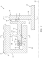
FIG. 1 is a partial side sectional illustration of an assembly for rotational equipment. -
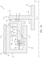
FIG. 1B is a partial side sectional illustration of the rotational equipment assembly configured with an additional spring structure. -
FIG. 2 is a cross-sectional illustration of a rotating structure taken along line 2-2 inFIG. 1 . -
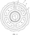
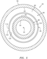
FIG. 3 is a cross-sectional illustration of a stationary structure and a seal assembly taken along line 3-3 inFIG. 1 . -
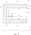
FIG. 4 is a partial side sectional illustration of the seal assembly shown without a spring structure and a seal shoe for ease of depiction. -
FIG. 5 is a cross-sectional illustration of the assembly ofFIG. 4 taken along line 5-5 inFIG. 4 . -
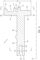
FIG. 6 is a partial side sectional illustration of the seal shoe. -
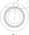
FIG. 7 is a cross-sectional illustration of the seal shoe taken along line 7-7 inFIG. 6 . -
FIG. 8 is an end view illustration of the seal shoe taken along line 8-8 inFIG. 6 . -
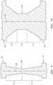
FIG. 9 is a side sectional illustration of a spring structure ligament extending between the seal carrier and the seal shoe. -
FIG. 10 is a cross-sectional illustration of the spring structure ligament extending between the seal carrier and the seal shoe. -
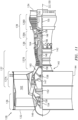
FIG. 11 is a side cutaway illustration of a geared turbofan gas turbine engine. -
FIG. 1 illustrates anassembly 20 for rotational equipment with anaxial centerline 22, whichaxial centerline 22 may also be an axis of rotation (e.g., a rotational axis) for one or more components of theassembly 20. An example of such rotational equipment is a gas turbine engine for an aircraft propulsion system, an exemplary embodiment of which is described below in further detail. However, theassembly 20 of the present disclosure is not limited to such an aircraft or gas turbine engine application. Theassembly 20, for example, may alternatively be configured with rotational equipment such as an industrial gas turbine engine, a wind turbine, a water turbine or any other apparatus in which a seal is provided between a stationary structure and a rotating structure; e.g., a rotor. - The
assembly 20 ofFIG. 1 includes astationary structure 24, arotating structure 26 and an adaptivenon-contact seal assembly 28; e.g., a hydrostatic (e.g., hydrodynamic) seal assembly. Theseal assembly 28 is mounted with thestationary structure 24 and configured to substantially seal an annular gap between thestationary structure 24 and therotating structure 26 as described below in further detail. Furthermore, in contrast to prior art seal assemblies, theseal assembly 28 may also be configured such that friction does not significantly adversely impact adaptability of theseal assembly 28 and, thus, does not significantly negatively impact seal performance or seal life as described below in further detail. - The
stationary structure 24 has an inner radialstationary structure surface 30. Thisstationary structure surface 30 may be substantially cylindrical, and extends circumferentially around and faces towards theaxial centerline 22. Thestationary structure surface 30 at least partially forms a bore in thestationary structure 24. This bore is sized to receive theseal assembly 28, which may be fixedly mounted to thestationary structure 24 by, for example, a press fit connection between theseal assembly 28 and thestationary structure surface 30. Theseal assembly 28, of course, may also or alternatively be fixedly attached to thestationary structure 24 using one or more other techniques / devices. - The
rotating structure 26 includes aseal land 32. Thisseal land 32 may be a discrete, unitary annular body. Alternatively, theseal land 32 may be configured with another component / portion (e.g., a shaft) of therotating structure 26 as shown inFIG. 1 . Theseal land 32 has an outerseal land surface 34, which extends axially between opposing first and second sealland side surfaces land side surface 36 is a radially extending surface, which may be exactly or substantially (e.g., within +/- 1 degree) perpendicular to theaxial centerline 22. The first sealland side surface 36 ofFIG. 2 is circumferentially and/or radially uninterrupted. The first sealland side surface 36, for example, extends circumferentially around theaxial centerline 22 and/or radially between opposing edges of thesurface 36 without any breaks; e.g., apertures and/or protrusions. The present disclosure, of course, is not limited to such an exemplary first sealland side surface 36. For example, in other embodiments, the first sealland side surface 36 may be circumferentially and/or radially interrupted by one or more apertures (e.g., grooves) and/or projections (e.g., ribs). Referring again toFIG. 1 , the first sealland side surface 36 may be an annular, planar (e.g., flat) surface. - The
seal assembly 28 ofFIGS. 1 and3 includes aseal carrier 40, aseal shoe 42 and a spring structure 44 (or a plurality ofspring structures 44 as shown inFIG. 1B ). Theseal assembly 28 ofFIGS. 1 and3 may also include one or moresecondary seal elements - Referring to
FIGS. 4 and5 , theseal carrier 40 extends circumferentially around theaxial centerline 22 thereby providing theseal carrier 40 with a full hoop (e.g., monolithic) body. Theseal carrier 40 extends axially along theaxial centerline 22 between a firstseal carrier side 50 and a secondseal carrier side 52. Theseal carrier 40 extends radially between an innerseal carrier side 54 and an outerseal carrier side 56. - The
seal carrier 40 is configured with a (e.g., annular)channel 58 and may thereby have a C-shaped side sectional geometry. Thischannel 58 extends circumferentially through theseal carrier 40 around theaxial centerline 22. Thechannel 58 extends axially into theseal carrier 40 from the secondseal carrier side 52 to achannel end surface 60, whichsurface 60 extends radially between inner and outerchannel side surfaces channel 58 extends radially within theseal carrier 40 between the inner and the outer channel side surfaces 62 and 64. The innerchannel side surface 62 extends axially along theaxial centerline 22 from the secondseal carrier side 52 to thechannel end surface 60. The outerchannel side surface 64 extends axially along theaxial centerline 22 from the secondseal carrier side 52 to thechannel end surface 60. The inner and the outer channel side surfaces 62 and 64 may each be exactly or substantially (e.g., within +/- 1 degree) parallel to theaxial centerline 22. - Referring to
FIGS. 6-8 , theseal shoe 42 extends circumferentially around theaxial centerline 22 thereby providing theseal shoe 42 with a full hoop (e.g., monolithic) body. Theseal shoe 42 extends radially between an innerseal shoe side 66 and an outerseal shoe side 68. Theseal shoe 42 extends axially between a firstseal shoe side 70 and a secondseal shoe side 72. Theseal shoe 42 includes aseal shoe base 74, one or more seal shoe projections 76-78 (e.g., ridges) and aseal shoe flange 80. - The
seal shoe base 74 extends circumferentially around theaxial centerline 22. Theseal shoe base 74 extends radially from the innerseal shoe side 66 to the outerseal shoe side 68. Theseal shoe base 74 is disposed at (e.g., on, adjacent or proximate) the secondseal shoe side 72, and extends axially between opposing seal shoe base surfaces 82 and 84. - The
seal shoe base 74 has a radial height 86 (seeFIG. 6 ), which is defined between the innerseal shoe side 66 and the outerseal shoe side 68. Thisradial height 86 may be equal to or less than aradial height 88 of the first sealland side surface 36; seeFIG. 2 . - The seal shoe projections 76-78 are disposed at the second
seal shoe side 72. Each of the seal shoe projections 76-78, for example, projects axially along theaxial centerline 22 out from the second sealshoe base surface 84 to a respective distal end. Each of the seal shoe projections 76-78 may be configured as an annular ridge; e.g., seeFIG. 8 . Each of the seal shoe projections 76-78, for example, extends circumferentially around theaxial centerline 22. Theseal shoe projection 77 is arranged radially between theseal shoe projections projections groove seal shoe 42. Theseal shoe projection 78 is disposed at the outerseal shoe side 68. Theseal shoe projection 76 is disposed approximately radially midway between the inner and the outer seal shoe sides 66 and 68. Theseal shoe 42 of the present disclosure, however, is not limited to the number, configurations and/or locations of the foregoing exemplary seal shoe projections 76-78. - The
seal shoe flange 80 extends circumferentially around theaxial centerline 22. Theseal shoe flange 80 extends radially between inner and outer flange side surfaces 94 and 96. Theseal shoe flange 80 and, for example, itssurfaces axial centerline 22 out from theseal shoe base 74 to a distal end at the firstseal shoe side 70. The inner and the outer flange side surfaces 94 and 96 may each be exactly or substantially (e.g., within +/- 1 degree) parallel to theaxial centerline 22. - The
seal shoe flange 80 is configured with a (e.g., annular)groove 98 and may thereby have an end portion with a C-shaped side sectional geometry. Thisgroove 98 extends circumferentially through theseal shoe flange 80 about theaxial centerline 22. Thegroove 98 extends axially into theseal shoe flange 80 from the firstseal shoe side 70 to agroove end surface 100, which surface 100 extends radially between inner and outer groove side surfaces 102 and 104. Thegroove 98 extends radially within theseal shoe flange 80 between the inner and the outer groove side surfaces 102 and 104. The innergroove side surface 102 extends axially along theaxial centerline 22 from the firstseal shoe side 70 to thegroove end surface 100. The outergroove side surface 104 extends axially along theaxial centerline 22 from the firstseal shoe side 70 to thegroove end surface 100. The inner and the outer groove side surfaces 102 and 104 may each be exactly or substantially (e.g., within +/- 1 degree) parallel to theaxial centerline 22. Each of the inner and the outer groove side surfaces 102 and 104 may be a cylindrical surface, which may be circumferentially and/or axially uninterrupted. - Referring to
FIG 3 , eachspring structure 44 includes one or more (e.g., flexible / compliant)ligaments 106; e.g., columnar members. Theseligaments 106 are arranged circumferentially about theaxial centerline 22 in an annular array. Each of theligaments 106 is connected to and extends radially between theseal shoe 42 and theseal carrier 40. In particular, eachligament 106 ofFIG. 3 projects radially out from the outerflange side surface 96 to the outerchannel side surface 64. Acenterline 108 of eachligament 106 may be exactly or substantially (e.g., within +/- 1 degree) perpendicular to theaxial centerline 22; however, the present disclosure is not limited thereto. - Referring to
FIGS. 9 and 10 , eachligament 106 tapers axially as thatligament 106 extends radially. For example, aninner portion 110 of theligament 106 ofFIG. 9 axially tapers as thatinner portion 110 extends radially outward from theseal shoe 42 towards theseal carrier 40. Similarly, anouter portion 112 of theligament 106 ofFIG. 9 axially tapers as thatouter portion 112 extends radially inward from theseal carrier 40 towards theseal shoe 42. The inner and theouter portions ligament 106. Alternatively, the inner and theouter portions ligament 106; e.g., similar to lateral taper ofFIG. 10 . Referring again toFIG. 9 , the axial taper of the inner and/or theouter portions centerline 108; however, the present disclosure is not limited thereto. - Referring now to
FIG. 10 , anotherinner portion 114 of theligament 106 may also or alternatively laterally (e.g., circumferentially) taper as thatinner portion 114 extends radially outward from theseal shoe 42 towards theseal carrier 40. Similarly, anotherouter portion 116 of theligament 106 ofFIG. 9 may also or alternatively laterally taper as thatouter portion 116 extends radially inward from theseal carrier 40 towards theseal shoe 42. The inner and theouter portions intermediate portion 118 of theligament 106, whichportion 118 may not be laterally tapered. Alternatively, the inner and theouter portions ligament 106; e.g., similar to axial taper ofFIG. 9 . Referring again toFIG. 10 , the lateral taper of the inner and/or theouter portions centerline 108; however, the present disclosure is not limited thereto. - Referring to
FIG. 1 , theligaments 106 and, thus, each spring structure 44 (e.g., flexibly / compliantly) couples theseal shoe 42 to theseal carrier 40 such that at least a portion of theseal shoe flange 80 is axially within thechannel 58. Each of theligaments 106 is configured to flex (e.g., elastically deform) during certain modes of operation. This flexure may enable theseal shoe 42 to slightly shift (e.g., slide and/or rotate) relative to theseal land 32 during operation. For example, theligaments 106 may enable theseal shoe 42 to shift axially (e.g., axially translate) along theaxial centerline 22. Theligaments 106 may also or alternatively enable theseal shoe 42 to shift circumferentially (e.g., rotate) about theaxial centerline 22. Such shifting may enable theseal assembly 28 to accommodate vibrations, pressure changes, etc. during operation. The shifting may also or alternatively enable a hydrostatic non-contact seal interface to be formed between theseal shoe 42 and its protrusions 76-78 and the first sealland side surface 36. - In the embodiment of
FIG. 1B , thespring structures 44 are axially spaced from one another by an axial distance / an axial gap. With such a configuration, thespring structures 44 may further maintain axial alignment of theseal shoe 42 with theseal land 32. - Referring to
FIGS. 4 and5 , thesecondary seal element 46 may be configured as a diving board seal element. Thesecondary seal element 46 ofFIGS. 4 and5 , for example, extends circumferentially around theaxial centerline 22. Thesecondary seal element 46 projects axially along theaxial centerline 22 out from thechannel end surface 60 to a distalseal element end 119. Thesecondary seal element 46 extends radially between inner and outer seal element surfaces 120 and 122. The inner and the outer seal element surfaces 120 and 122 may each be exactly or substantially (e.g., within +/- 1 degree) parallel to theaxial centerline 22. Each of the inner and the outer seal element surfaces 120 and 122 may be a cylindrical surface, which may be circumferentially and/or axially uninterrupted. Referring toFIG. 1 , the distalseal element end 119 is disposed within thegroove 98. Thesecondary seal element 46, for example, projects axially out from theseal carrier 40 and into thegroove 98 so as to form a labyrinth seal with a portion of theseal shoe 42 that includes thegroove 98. - While the
secondary seal element 46 and the seal shoe form a labyrinth seal, under certain conditions, thesecondary seal element 46 may also touch (e.g., contact) one of the groove surfaces 102 and 104; e.g., thesurface 104. Such contact may enable thesecondary seal element 46 to damp vibrations in theseal shoe 42. Thesecondary seal element 46 may thereby also be configured as a mechanical seal shoe damper. - Referring again to
FIGS. 4 and5 , thesecondary seal element 48 may be configured as a knife edge seal element. Thesecondary seal element 48 ofFIGS. 4 and5 , for example, extends circumferentially around theaxial centerline 22. Thesecondary seal element 48 projects radially outwards from the innerchannel side surface 62 to a relatively sharpdistal edge 124; e.g., a knife edge. More particularly, thesecondary seal element 48 may axially taper as theelement 48 extends from theseal carrier 40 to itsdistal edge 124. Referring toFIG. 1 , thedistal edge 124 is positioned in close proximity to (e.g., next to but slightly spaced from, or alternatively touching) the innerflange side surface 94 so as to form a knife edge seal with a portion of theseal shoe 42 that includes thesurface 94. - During operation of the assembly of
FIG. 1 , the rotatingstructure 26 rotates about theaxial centerline 22. When the rotatingstructure 26 is static and/or rotating a relatively low speeds (e.g., thestructure 26 just starts rotating), theseal shoe 42 and one or more of its protrusions 76-78 (e.g., the protrusion 76)) may contact or be in close proximity to theseal land 32 and itssurface 36. However, as the speed of the rotatingstructure 26 increases, the gap between theseal shoe 42 and theseal land 32 may increase as, for example, a hydrodynamic seal is formed between theseal shoe 42 and theseal land 32. While this seal between theseal shoe 42 and theseal land 32 blocks a majority of fluid leakage between thestructures apertures 126 defined circumferentially between the ligaments 106 (seeFIG. 3 ) is blocked by one or both of thesecondary seal elements seal assembly 28 thereby may substantially seal the gap between thestationary structure 24 and the rotatingstructure 26. - In addition to reducing fluid leakage through the
apertures 126, thesecondary seal element 48 also serves to reduce a pressure drop across thesecondary seal element 46. As a result, a pressure forces pressing thesecondary seal element 46 against theseal shoe 42 may be much smaller than if thesecondary seal element 48 was omitted. This smaller pressure force results in provision of a relatively small friction force between thesecondary seal element 46 and theseal shoe 42. Maintaining this friction force small may ensure theseal shoe 42 can freely move (e.g., axially translate) relative to thesecondary seal element 46 and, thus, reducing the impact of friction on adaptability of theseal assembly 28. - In some embodiments, one or more or each of the
seal assembly elements seal assembly elements seal assembly elements -
FIG. 11 is a side cutaway illustration of a gearedturbine engine 128 with which theassembly 20 ofFIG. 1 may be configured. Thisturbine engine 128 extends along an axial centerline 130 (e.g., theaxial centerline 22 of the assembly 20) between anupstream airflow inlet 132 and adownstream airflow exhaust 134. Theturbine engine 128 includes afan section 136, acompressor section 137, acombustor section 138 and aturbine section 139. Thecompressor section 137 includes a low pressure compressor (LPC)section 137A and a high pressure compressor (HPC)section 137B. Theturbine section 139 includes a high pressure turbine (HPT)section 139A and a low pressure turbine (LPT)section 139B. - The engine sections 136-139 are arranged sequentially along the centerline 130 within an
engine housing 140, which may include thestationary structure 24 ofFIG. 1 . Thehousing 140 includes an inner case 142 (e.g., a core case) and an outer case 144 (e.g., a fan case). Theinner case 142 may house one or more of the engine sections 137-139; e.g., an engine core. Theouter case 144 may house at least thefan section 136. - Each of the
engine sections - The
fan rotor 146 is connected to agear train 152, for example, through afan shaft 154. Thegear train 152 and theLPC rotor 147 are connected to and driven by theLPT rotor 150 through alow speed shaft 155. TheHPC rotor 148 is connected to and driven by theHPT rotor 149 through ahigh speed shaft 156. Any one of these shafts 154-156 may be included in or otherwise connected to / rotatable with the rotatingstructure 26 ofFIG. 1 . Referring again toFIG. 11 , the shafts 154-156 are rotatably supported by a plurality ofbearings 158; e.g., rolling element and/or thrust bearings. Each of thesebearings 158 is connected to theengine housing 140 by at least one stationary structure such as, for example, an annular support strut. - During operation, air enters the
turbine engine 128 through theairflow inlet 132. This air is directed through thefan section 136 and into acore gas path 160 and abypass gas path 162. Thecore gas path 160 extends sequentially through the engine sections 13-139. The air within thecore gas path 160 may be referred to as "core air". Thebypass gas path 162 extends through a bypass duct, which bypasses the engine core. The air within thebypass gas path 162 may be referred to as "bypass air". - The core air is compressed by the
compressor rotors combustion chamber 164 of a combustor in thecombustor section 138. Fuel is injected into thecombustion chamber 164 and mixed with the compressed core air to provide a fuel-air mixture. This fuel air mixture is ignited and combustion products thereof flow through and sequentially cause theturbine rotors turbine rotors compressor rotors turbine rotor 150 also drives rotation of thefan rotor 146, which propels bypass air through and out of thebypass gas path 162. The propulsion of the bypass air may account for a majority of thrust generated by theturbine engine 128, e.g., more than seventy-five percent (75%) of engine thrust. Theturbine engine 128 of the present disclosure, however, is not limited to the foregoing exemplary thrust ratio. - The
assembly 20 may be included in various turbine engines other than the one described above as well as in other types of rotational equipment. Theassembly 20, for example, may be included in a geared turbine engine where a gear train connects one or more shafts to one or more rotors in a fan section, a compressor section and/or any other engine section. Alternatively, theassembly 20 may be included in a turbine engine configured without a gear train. Theassembly 20 may be included in a geared or non-geared turbine engine configured with a single spool, with two spools (e.g., seeFIG. 11 ), or with more than two spools. The turbine engine may be configured as a turbofan engine, a turbojet engine, a propfan engine, a pusher fan engine or any other type of turbine engine. The present disclosure therefore is not limited to any particular types or configurations of turbine engines or rotational equipment. - While various embodiments of the present disclosure have been described, it will be apparent to those of ordinary skill in the art that many more embodiments and implementations are possible within the scope of the disclosure as defined by the claims. Accordingly, the present invention is not to be restricted except in light of the claims.
Claims (13)
- An assembly (20) for rotational equipment, comprising:a stationary structure (24);a rotating structure (26) rotatable about an axial centerline (22); anda non-contact seal assembly (28) configured to substantially seal an annular gap between the stationary structure (24) and the rotating structure (26), the non-contact seal assembly (28) comprising a seal shoe (42) configured to sealingly engage the rotating structure (26) axially along the axial centerline (22),wherein the non-contact seal assembly (28) further comprises a seal carrier (40) and a spring structure (44),wherein the seal carrier (40) is mounted to the stationary structure (24), andwherein the spring structure (44) flexibly connects the seal shoe (42) to the seal carrier (40),wherein the spring structure (44) comprises a plurality of ligaments (106) arranged in an annular array about the axial centerline (22),wherein each of the plurality of ligaments (106) extends radially out from the seal shoe (42) to the seal carrier (40),characterised in that a first of the plurality of ligaments (106) is axially tapered.
- The assembly of claim 1, wherein the non-contact seal assembly (28) is configured as a hydrostatic seal assembly.
- The assembly of claim 1 or 2, wherein the seal shoe (42) is a monolithic full hoop body.
- The assembly of claim 1, 2 or 3, wherein the seal shoe (42) includes a seal shoe base (74) and a seal shoe projection (76-78) that projects axially along the axial centerline (22) out from the seal shoe base (74) towards the rotating structure (26).
- The assembly of any preceding claim, wherein:the seal shoe (42) sealingly engages and is axially adjacent a radially extending surface (36) of the rotating structure (26);the radially extending surface (36) of the rotating structure has a first radial height (88); andthe seal shoe (42) has a second radial height (86) that is less than or equal to the first radial height (88).
- The assembly of any preceding claim, whereinthe non-contact seal assembly (28) further comprises a second spring structure (44); andthe second spring structure (44) further flexibly connects the seal shoe (42) to the seal carrier (40).
- The assembly of any preceding claim, wherein the seal shoe (42) projects axially along the axial centerline (22) into a channel (58) in the seal carrier (40).
- The assembly of any preceding claim, wherein at least the seal shoe (42), the seal carrier (40) and the plurality of ligaments (106) are configured as a monolithic body.
- The assembly of any preceding claim, wherein a majority or all of the plurality of ligaments (106) are axially tapered.
- The assembly of any preceding claim, wherein the seal shoe (42) is configured to axially and/or circumferentially shift relative to the seal carrier (40).
- The assembly of any preceding claim, wherein a labyrinth seal element (46) projects axially along the axial centerline (22) out from the seal carrier (40) and into a groove (102) in the seal shoe (42) such that the labyrinth seal element (46) and a portion of the seal shoe (42) with the groove (106) form a labyrinth seal.
- The assembly of any preceding claim, wherein a knife-edge seal element (48) projects radially out from the seal carrier (40) towards an axially extending surface (94) of the seal shoe (42) such that the knife-edge seal element (48) and a portion of the seal shoe (42) with the axially extending surface (94) form a knife-edge seal.
- The assembly of any preceding claim, wherein a centerline (108) of each of the plurality of ligaments (106) is perpendicular to the axial centerline (22).
Priority Applications (1)
| Application Number | Priority Date | Filing Date | Title |
|---|---|---|---|
| EP23184837.5A EP4269841A1 (en) | 2019-08-23 | 2020-08-24 | Non-contact seal with axial arrangement |
Applications Claiming Priority (1)
| Application Number | Priority Date | Filing Date | Title |
|---|---|---|---|
| US201962891041P | 2019-08-23 | 2019-08-23 |
Related Child Applications (1)
| Application Number | Title | Priority Date | Filing Date |
|---|---|---|---|
| EP23184837.5A Division EP4269841A1 (en) | 2019-08-23 | 2020-08-24 | Non-contact seal with axial arrangement |
Publications (2)
| Publication Number | Publication Date |
|---|---|
| EP3783249A1 EP3783249A1 (en) | 2021-02-24 |
| EP3783249B1 true EP3783249B1 (en) | 2023-07-12 |
Family
ID=72234778
Family Applications (2)
| Application Number | Title | Priority Date | Filing Date |
|---|---|---|---|
| EP20192505.4A Active EP3783249B1 (en) | 2019-08-23 | 2020-08-24 | Non-contact seal with axial arrangement |
| EP23184837.5A Pending EP4269841A1 (en) | 2019-08-23 | 2020-08-24 | Non-contact seal with axial arrangement |
Family Applications After (1)
| Application Number | Title | Priority Date | Filing Date |
|---|---|---|---|
| EP23184837.5A Pending EP4269841A1 (en) | 2019-08-23 | 2020-08-24 | Non-contact seal with axial arrangement |
Country Status (2)
| Country | Link |
|---|---|
| US (1) | US11493135B2 (en) |
| EP (2) | EP3783249B1 (en) |
Family Cites Families (37)
| Publication number | Priority date | Publication date | Assignee | Title |
|---|---|---|---|---|
| US6428009B2 (en) * | 2000-04-03 | 2002-08-06 | John F. Justak | Robust hydrodynamic brush seal |
| US20040217549A1 (en) * | 2003-05-01 | 2004-11-04 | Justak John F. | Hydrodynamic brush seal |
| US7896352B2 (en) * | 2003-05-01 | 2011-03-01 | Justak John F | Seal with stacked sealing elements |
| US8172232B2 (en) * | 2003-05-01 | 2012-05-08 | Advanced Technologies Group, Inc. | Non-contact seal for a gas turbine engine |
| US8002285B2 (en) * | 2003-05-01 | 2011-08-23 | Justak John F | Non-contact seal for a gas turbine engine |
| US7410173B2 (en) * | 2003-05-01 | 2008-08-12 | Justak John F | Hydrodynamic brush seal |
| US8641045B2 (en) * | 2003-05-01 | 2014-02-04 | Advanced Technologies Group, Inc. | Seal with stacked sealing elements |
| US8919781B2 (en) * | 2003-05-01 | 2014-12-30 | Advanced Technologies Group, Inc. | Self-adjusting non-contact seal |
| US20110150640A1 (en) * | 2003-08-21 | 2011-06-23 | Peter Tiemann | Labyrinth Seal in a Stationary Gas Turbine |
| US20070253809A1 (en) * | 2006-05-01 | 2007-11-01 | General Electric Company | Methods and apparatus for assembling gas turbine engines |
| US20090033037A1 (en) * | 2007-07-30 | 2009-02-05 | Varanasi Kripa K | Seal assembly |
| US8820752B2 (en) * | 2008-09-15 | 2014-09-02 | Stein Seal Company | Intershaft seal with centrifugal compensation |
| US8740225B2 (en) * | 2009-06-03 | 2014-06-03 | Exponential Technologies, Inc. | Hydrodynamic bore seal |
| CN102362109B (en) * | 2009-06-16 | 2016-01-20 | 三菱重工业株式会社 | Gland seal device |
| US9097350B2 (en) | 2012-04-02 | 2015-08-04 | United Technologies Corporation | Axial non-contact seal |
| US9115810B2 (en) * | 2012-10-31 | 2015-08-25 | General Electric Company | Pressure actuated film riding seals for turbo machinery |
| WO2014107161A1 (en) * | 2013-01-04 | 2014-07-10 | United Technologies Corporation | Seal assembly for arranging between a stator and a rotor |
| EP2759675A1 (en) * | 2013-01-28 | 2014-07-30 | Siemens Aktiengesellschaft | Turbine arrangement with improved sealing effect at a seal |
| US9650906B2 (en) | 2013-03-08 | 2017-05-16 | Rolls-Royce Corporation | Slotted labyrinth seal |
| US10119474B2 (en) * | 2013-03-15 | 2018-11-06 | United Technologies Corporation | Vibration damping apparatus for hydrostatic seal of gas turbine engine |
| WO2015147967A1 (en) * | 2014-03-27 | 2015-10-01 | United Technologies Corporation | Gas turbine engine and seal assembly therefore |
| US20150285152A1 (en) * | 2014-04-03 | 2015-10-08 | United Technologies Corporation | Gas turbine engine and seal assembly therefore |
| US10801348B2 (en) * | 2014-10-14 | 2020-10-13 | Raytheon Technologies Corporation | Non-contacting dynamic seal |
| US9988921B2 (en) * | 2014-10-17 | 2018-06-05 | United Technologies Corporation | Circumferential seal with seal dampening elements |
| US10370991B2 (en) * | 2014-11-07 | 2019-08-06 | United Technologies Corporation | Gas turbine engine and seal assembly therefore |
| US10794208B2 (en) * | 2015-07-08 | 2020-10-06 | Raytheon Technologies Corporation | Non-contact seal assembly for rotational equipment with linkage between adjacent rotors |
| US10107126B2 (en) * | 2015-08-19 | 2018-10-23 | United Technologies Corporation | Non-contact seal assembly for rotational equipment |
| US20170051751A1 (en) * | 2015-08-19 | 2017-02-23 | United Technologies Corporation | Seal assembly for rotational equipment |
| US10094241B2 (en) * | 2015-08-19 | 2018-10-09 | United Technologies Corporation | Non-contact seal assembly for rotational equipment |
| US10221714B2 (en) * | 2016-01-22 | 2019-03-05 | United Technologies Corporation | Secondary seal device(s) with alignment tab(s) |
| US10030531B2 (en) * | 2016-01-22 | 2018-07-24 | United Technologies Corporation | Seal shoe for a hydrostatic non-contact seal device |
| US10428672B2 (en) * | 2016-02-08 | 2019-10-01 | United Technologies Corporation | Floating, non-contact seal and dimensions thereof |
| US10060535B2 (en) * | 2016-02-25 | 2018-08-28 | United Technologies Corporation | Shaped spring element for a non-contact seal device |
| US10890082B2 (en) * | 2016-05-11 | 2021-01-12 | General Electric Company | Aspirating face seal tooth configuration |
| US10415413B2 (en) * | 2016-09-01 | 2019-09-17 | United Technologies Corporation | Floating non-contact seal vertical lip |
| US10184347B1 (en) * | 2017-07-18 | 2019-01-22 | United Technologies Corporation | Non-contact seal with resilient biasing element(s) |
| NL2022585B1 (en) | 2019-02-15 | 2020-08-28 | Lagersmit Sealing Solutions B V | Radial sealing system |
-
2020
- 2020-08-24 EP EP20192505.4A patent/EP3783249B1/en active Active
- 2020-08-24 US US17/000,815 patent/US11493135B2/en active Active
- 2020-08-24 EP EP23184837.5A patent/EP4269841A1/en active Pending
Also Published As
| Publication number | Publication date |
|---|---|
| EP4269841A1 (en) | 2023-11-01 |
| EP3783249A1 (en) | 2021-02-24 |
| US20210054938A1 (en) | 2021-02-25 |
| US11493135B2 (en) | 2022-11-08 |
Similar Documents
| Publication | Publication Date | Title |
|---|---|---|
| US10208615B2 (en) | Seal shoe for a hydrostatic non-contact seal device | |
| US10563532B2 (en) | Non-contact seal with monolithic/unitary carrier structure | |
| EP3431838B1 (en) | Non-contact seal with resilient biasing element(s) | |
| US10697550B2 (en) | Non-contact seal with progressive radial stop(s) | |
| US8657573B2 (en) | Circumferential sealing arrangement | |
| US10370996B2 (en) | Floating, non-contact seal with offset build clearance for load imbalance | |
| US10830081B2 (en) | Non-contact seal with non-straight spring beam(s) | |
| US10641180B2 (en) | Hydrostatic non-contact seal with varied thickness beams | |
| US10337621B2 (en) | Hydrostatic non-contact seal with weight reduction pocket | |
| EP3290755A1 (en) | Floating, non-contact seal with at least three beams | |
| US11415227B2 (en) | Non-contact seal assembly with chamfered seal shoe | |
| EP3819528B1 (en) | Cartridge seal assembly for rotational equipment | |
| EP3961070A1 (en) | Controlled contact surface for a secondary seal in a non-contact seal assembly | |
| US20190017404A1 (en) | Hydrostatic non-contact seal with seal carrier elimination | |
| EP3409885B1 (en) | Deflection spring seal | |
| US10731761B2 (en) | Hydrostatic non-contact seal with offset outer ring | |
| EP3933233A1 (en) | Non-contact seal assembly with multiple axially spaced spring elements | |
| EP3739241B1 (en) | Brush secondary seal for cantilevered hydrostatic advanced low leakage seal | |
| EP3783249B1 (en) | Non-contact seal with axial arrangement | |
| US11365640B2 (en) | Seal assembly with anti-rotation lock |
Legal Events
| Date | Code | Title | Description |
|---|---|---|---|
| PUAI | Public reference made under article 153(3) epc to a published international application that has entered the european phase |
Free format text: ORIGINAL CODE: 0009012 |
|
| STAA | Information on the status of an ep patent application or granted ep patent |
Free format text: STATUS: THE APPLICATION HAS BEEN PUBLISHED |
|
| AK | Designated contracting states |
Kind code of ref document: A1 Designated state(s): AL AT BE BG CH CY CZ DE DK EE ES FI FR GB GR HR HU IE IS IT LI LT LU LV MC MK MT NL NO PL PT RO RS SE SI SK SM TR |
|
| AX | Request for extension of the european patent |
Extension state: BA ME |
|
| STAA | Information on the status of an ep patent application or granted ep patent |
Free format text: STATUS: REQUEST FOR EXAMINATION WAS MADE |
|
| 17P | Request for examination filed |
Effective date: 20210824 |
|
| RBV | Designated contracting states (corrected) |
Designated state(s): AL AT BE BG CH CY CZ DE DK EE ES FI FR GB GR HR HU IE IS IT LI LT LU LV MC MK MT NL NO PL PT RO RS SE SI SK SM TR |
|
| GRAP | Despatch of communication of intention to grant a patent |
Free format text: ORIGINAL CODE: EPIDOSNIGR1 |
|
| STAA | Information on the status of an ep patent application or granted ep patent |
Free format text: STATUS: GRANT OF PATENT IS INTENDED |
|
| RIC1 | Information provided on ipc code assigned before grant |
Ipc: F16J 15/44 20060101ALI20221216BHEP Ipc: F01D 11/02 20060101ALI20221216BHEP Ipc: F16J 15/34 20060101AFI20221216BHEP |
|
| INTG | Intention to grant announced |
Effective date: 20230123 |
|
| GRAS | Grant fee paid |
Free format text: ORIGINAL CODE: EPIDOSNIGR3 |
|
| GRAA | (expected) grant |
Free format text: ORIGINAL CODE: 0009210 |
|
| STAA | Information on the status of an ep patent application or granted ep patent |
Free format text: STATUS: THE PATENT HAS BEEN GRANTED |
|
| AK | Designated contracting states |
Kind code of ref document: B1 Designated state(s): AL AT BE BG CH CY CZ DE DK EE ES FI FR GB GR HR HU IE IS IT LI LT LU LV MC MK MT NL NO PL PT RO RS SE SI SK SM TR |
|
| REG | Reference to a national code |
Ref country code: CH Ref legal event code: EP |
|
| REG | Reference to a national code |
Ref country code: IE Ref legal event code: FG4D |
|
| REG | Reference to a national code |
Ref country code: DE Ref legal event code: R096 Ref document number: 602020013563 Country of ref document: DE |
|
| RAP4 | Party data changed (patent owner data changed or rights of a patent transferred) |
Owner name: RTX CORPORATION |
|
| REG | Reference to a national code |
Ref country code: LT Ref legal event code: MG9D |
|
| REG | Reference to a national code |
Ref country code: NL Ref legal event code: MP Effective date: 20230712 |
|
| PGFP | Annual fee paid to national office [announced via postgrant information from national office to epo] |
Ref country code: FR Payment date: 20230822 Year of fee payment: 4 Ref country code: DE Payment date: 20230720 Year of fee payment: 4 |
|
| REG | Reference to a national code |
Ref country code: AT Ref legal event code: MK05 Ref document number: 1587508 Country of ref document: AT Kind code of ref document: T Effective date: 20230712 |
|
| PG25 | Lapsed in a contracting state [announced via postgrant information from national office to epo] |
Ref country code: NL Free format text: LAPSE BECAUSE OF FAILURE TO SUBMIT A TRANSLATION OF THE DESCRIPTION OR TO PAY THE FEE WITHIN THE PRESCRIBED TIME-LIMIT Effective date: 20230712 |
|
| PG25 | Lapsed in a contracting state [announced via postgrant information from national office to epo] |
Ref country code: GR Free format text: LAPSE BECAUSE OF FAILURE TO SUBMIT A TRANSLATION OF THE DESCRIPTION OR TO PAY THE FEE WITHIN THE PRESCRIBED TIME-LIMIT Effective date: 20231013 |
|
| PG25 | Lapsed in a contracting state [announced via postgrant information from national office to epo] |
Ref country code: ES Free format text: LAPSE BECAUSE OF FAILURE TO SUBMIT A TRANSLATION OF THE DESCRIPTION OR TO PAY THE FEE WITHIN THE PRESCRIBED TIME-LIMIT Effective date: 20230712 |
|
| PG25 | Lapsed in a contracting state [announced via postgrant information from national office to epo] |
Ref country code: IS Free format text: LAPSE BECAUSE OF FAILURE TO SUBMIT A TRANSLATION OF THE DESCRIPTION OR TO PAY THE FEE WITHIN THE PRESCRIBED TIME-LIMIT Effective date: 20231112 |
|
| PG25 | Lapsed in a contracting state [announced via postgrant information from national office to epo] |
Ref country code: SE Free format text: LAPSE BECAUSE OF FAILURE TO SUBMIT A TRANSLATION OF THE DESCRIPTION OR TO PAY THE FEE WITHIN THE PRESCRIBED TIME-LIMIT Effective date: 20230712 Ref country code: RS Free format text: LAPSE BECAUSE OF FAILURE TO SUBMIT A TRANSLATION OF THE DESCRIPTION OR TO PAY THE FEE WITHIN THE PRESCRIBED TIME-LIMIT Effective date: 20230712 Ref country code: PT Free format text: LAPSE BECAUSE OF FAILURE TO SUBMIT A TRANSLATION OF THE DESCRIPTION OR TO PAY THE FEE WITHIN THE PRESCRIBED TIME-LIMIT Effective date: 20231113 Ref country code: NO Free format text: LAPSE BECAUSE OF FAILURE TO SUBMIT A TRANSLATION OF THE DESCRIPTION OR TO PAY THE FEE WITHIN THE PRESCRIBED TIME-LIMIT Effective date: 20231012 Ref country code: LV Free format text: LAPSE BECAUSE OF FAILURE TO SUBMIT A TRANSLATION OF THE DESCRIPTION OR TO PAY THE FEE WITHIN THE PRESCRIBED TIME-LIMIT Effective date: 20230712 Ref country code: LT Free format text: LAPSE BECAUSE OF FAILURE TO SUBMIT A TRANSLATION OF THE DESCRIPTION OR TO PAY THE FEE WITHIN THE PRESCRIBED TIME-LIMIT Effective date: 20230712 Ref country code: IS Free format text: LAPSE BECAUSE OF FAILURE TO SUBMIT A TRANSLATION OF THE DESCRIPTION OR TO PAY THE FEE WITHIN THE PRESCRIBED TIME-LIMIT Effective date: 20231112 Ref country code: HR Free format text: LAPSE BECAUSE OF FAILURE TO SUBMIT A TRANSLATION OF THE DESCRIPTION OR TO PAY THE FEE WITHIN THE PRESCRIBED TIME-LIMIT Effective date: 20230712 Ref country code: GR Free format text: LAPSE BECAUSE OF FAILURE TO SUBMIT A TRANSLATION OF THE DESCRIPTION OR TO PAY THE FEE WITHIN THE PRESCRIBED TIME-LIMIT Effective date: 20231013 Ref country code: FI Free format text: LAPSE BECAUSE OF FAILURE TO SUBMIT A TRANSLATION OF THE DESCRIPTION OR TO PAY THE FEE WITHIN THE PRESCRIBED TIME-LIMIT Effective date: 20230712 Ref country code: ES Free format text: LAPSE BECAUSE OF FAILURE TO SUBMIT A TRANSLATION OF THE DESCRIPTION OR TO PAY THE FEE WITHIN THE PRESCRIBED TIME-LIMIT Effective date: 20230712 Ref country code: AT Free format text: LAPSE BECAUSE OF FAILURE TO SUBMIT A TRANSLATION OF THE DESCRIPTION OR TO PAY THE FEE WITHIN THE PRESCRIBED TIME-LIMIT Effective date: 20230712 |
|
| PG25 | Lapsed in a contracting state [announced via postgrant information from national office to epo] |
Ref country code: PL Free format text: LAPSE BECAUSE OF FAILURE TO SUBMIT A TRANSLATION OF THE DESCRIPTION OR TO PAY THE FEE WITHIN THE PRESCRIBED TIME-LIMIT Effective date: 20230712 |
|
| REG | Reference to a national code |
Ref country code: CH Ref legal event code: PL |
|
| PG25 | Lapsed in a contracting state [announced via postgrant information from national office to epo] |
Ref country code: LU Free format text: LAPSE BECAUSE OF NON-PAYMENT OF DUE FEES Effective date: 20230824 |