EP3431838B1 - Non-contact seal with resilient biasing element(s) - Google Patents
Non-contact seal with resilient biasing element(s) Download PDFInfo
- Publication number
- EP3431838B1 EP3431838B1 EP18173373.4A EP18173373A EP3431838B1 EP 3431838 B1 EP3431838 B1 EP 3431838B1 EP 18173373 A EP18173373 A EP 18173373A EP 3431838 B1 EP3431838 B1 EP 3431838B1
- Authority
- EP
- European Patent Office
- Prior art keywords
- seal
- mount
- assembly
- spring
- spring elements
- Prior art date
- Legal status (The legal status is an assumption and is not a legal conclusion. Google has not performed a legal analysis and makes no representation as to the accuracy of the status listed.)
- Active
Links
- 230000003993 interaction Effects 0.000 description 4
- 230000000712 assembly Effects 0.000 description 3
- 238000000429 assembly Methods 0.000 description 3
- 238000002485 combustion reaction Methods 0.000 description 3
- 239000012530 fluid Substances 0.000 description 3
- 230000002706 hydrostatic effect Effects 0.000 description 3
- 230000014759 maintenance of location Effects 0.000 description 3
- 239000000446 fuel Substances 0.000 description 2
- 239000000203 mixture Substances 0.000 description 2
- XLYOFNOQVPJJNP-UHFFFAOYSA-N water Substances O XLYOFNOQVPJJNP-UHFFFAOYSA-N 0.000 description 2
- 230000004323 axial length Effects 0.000 description 1
- 230000015572 biosynthetic process Effects 0.000 description 1
- 230000006835 compression Effects 0.000 description 1
- 238000007906 compression Methods 0.000 description 1
- 238000004519 manufacturing process Methods 0.000 description 1
- 239000000463 material Substances 0.000 description 1
- 238000000034 method Methods 0.000 description 1
- 238000007789 sealing Methods 0.000 description 1
- 238000011144 upstream manufacturing Methods 0.000 description 1
Images


Classifications
-
- F—MECHANICAL ENGINEERING; LIGHTING; HEATING; WEAPONS; BLASTING
- F01—MACHINES OR ENGINES IN GENERAL; ENGINE PLANTS IN GENERAL; STEAM ENGINES
- F01D—NON-POSITIVE DISPLACEMENT MACHINES OR ENGINES, e.g. STEAM TURBINES
- F01D11/00—Preventing or minimising internal leakage of working-fluid, e.g. between stages
- F01D11/02—Preventing or minimising internal leakage of working-fluid, e.g. between stages by non-contact sealings, e.g. of labyrinth type
- F01D11/025—Seal clearance control; Floating assembly; Adaptation means to differential thermal dilatations
-
- F—MECHANICAL ENGINEERING; LIGHTING; HEATING; WEAPONS; BLASTING
- F01—MACHINES OR ENGINES IN GENERAL; ENGINE PLANTS IN GENERAL; STEAM ENGINES
- F01D—NON-POSITIVE DISPLACEMENT MACHINES OR ENGINES, e.g. STEAM TURBINES
- F01D11/00—Preventing or minimising internal leakage of working-fluid, e.g. between stages
- F01D11/02—Preventing or minimising internal leakage of working-fluid, e.g. between stages by non-contact sealings, e.g. of labyrinth type
-
- F—MECHANICAL ENGINEERING; LIGHTING; HEATING; WEAPONS; BLASTING
- F01—MACHINES OR ENGINES IN GENERAL; ENGINE PLANTS IN GENERAL; STEAM ENGINES
- F01D—NON-POSITIVE DISPLACEMENT MACHINES OR ENGINES, e.g. STEAM TURBINES
- F01D11/00—Preventing or minimising internal leakage of working-fluid, e.g. between stages
- F01D11/08—Preventing or minimising internal leakage of working-fluid, e.g. between stages for sealing space between rotor blade tips and stator
- F01D11/14—Adjusting or regulating tip-clearance, i.e. distance between rotor-blade tips and stator casing
- F01D11/16—Adjusting or regulating tip-clearance, i.e. distance between rotor-blade tips and stator casing by self-adjusting means
-
- F—MECHANICAL ENGINEERING; LIGHTING; HEATING; WEAPONS; BLASTING
- F16—ENGINEERING ELEMENTS AND UNITS; GENERAL MEASURES FOR PRODUCING AND MAINTAINING EFFECTIVE FUNCTIONING OF MACHINES OR INSTALLATIONS; THERMAL INSULATION IN GENERAL
- F16J—PISTONS; CYLINDERS; SEALINGS
- F16J15/00—Sealings
- F16J15/44—Free-space packings
- F16J15/441—Free-space packings with floating ring
- F16J15/442—Free-space packings with floating ring segmented
-
- F—MECHANICAL ENGINEERING; LIGHTING; HEATING; WEAPONS; BLASTING
- F16—ENGINEERING ELEMENTS AND UNITS; GENERAL MEASURES FOR PRODUCING AND MAINTAINING EFFECTIVE FUNCTIONING OF MACHINES OR INSTALLATIONS; THERMAL INSULATION IN GENERAL
- F16J—PISTONS; CYLINDERS; SEALINGS
- F16J15/00—Sealings
- F16J15/44—Free-space packings
- F16J15/445—Free-space packings with means for adjusting the clearance
-
- F—MECHANICAL ENGINEERING; LIGHTING; HEATING; WEAPONS; BLASTING
- F16—ENGINEERING ELEMENTS AND UNITS; GENERAL MEASURES FOR PRODUCING AND MAINTAINING EFFECTIVE FUNCTIONING OF MACHINES OR INSTALLATIONS; THERMAL INSULATION IN GENERAL
- F16J—PISTONS; CYLINDERS; SEALINGS
- F16J15/00—Sealings
- F16J15/44—Free-space packings
- F16J15/447—Labyrinth packings
-
- F—MECHANICAL ENGINEERING; LIGHTING; HEATING; WEAPONS; BLASTING
- F01—MACHINES OR ENGINES IN GENERAL; ENGINE PLANTS IN GENERAL; STEAM ENGINES
- F01D—NON-POSITIVE DISPLACEMENT MACHINES OR ENGINES, e.g. STEAM TURBINES
- F01D11/00—Preventing or minimising internal leakage of working-fluid, e.g. between stages
- F01D11/003—Preventing or minimising internal leakage of working-fluid, e.g. between stages by packing rings; Mechanical seals
-
- F—MECHANICAL ENGINEERING; LIGHTING; HEATING; WEAPONS; BLASTING
- F02—COMBUSTION ENGINES; HOT-GAS OR COMBUSTION-PRODUCT ENGINE PLANTS
- F02C—GAS-TURBINE PLANTS; AIR INTAKES FOR JET-PROPULSION PLANTS; CONTROLLING FUEL SUPPLY IN AIR-BREATHING JET-PROPULSION PLANTS
- F02C7/00—Features, components parts, details or accessories, not provided for in, or of interest apart form groups F02C1/00 - F02C6/00; Air intakes for jet-propulsion plants
- F02C7/28—Arrangement of seals
-
- F—MECHANICAL ENGINEERING; LIGHTING; HEATING; WEAPONS; BLASTING
- F05—INDEXING SCHEMES RELATING TO ENGINES OR PUMPS IN VARIOUS SUBCLASSES OF CLASSES F01-F04
- F05D—INDEXING SCHEME FOR ASPECTS RELATING TO NON-POSITIVE-DISPLACEMENT MACHINES OR ENGINES, GAS-TURBINES OR JET-PROPULSION PLANTS
- F05D2220/00—Application
- F05D2220/30—Application in turbines
- F05D2220/32—Application in turbines in gas turbines
-
- F—MECHANICAL ENGINEERING; LIGHTING; HEATING; WEAPONS; BLASTING
- F05—INDEXING SCHEMES RELATING TO ENGINES OR PUMPS IN VARIOUS SUBCLASSES OF CLASSES F01-F04
- F05D—INDEXING SCHEME FOR ASPECTS RELATING TO NON-POSITIVE-DISPLACEMENT MACHINES OR ENGINES, GAS-TURBINES OR JET-PROPULSION PLANTS
- F05D2240/00—Components
- F05D2240/10—Stators
-
- F—MECHANICAL ENGINEERING; LIGHTING; HEATING; WEAPONS; BLASTING
- F05—INDEXING SCHEMES RELATING TO ENGINES OR PUMPS IN VARIOUS SUBCLASSES OF CLASSES F01-F04
- F05D—INDEXING SCHEME FOR ASPECTS RELATING TO NON-POSITIVE-DISPLACEMENT MACHINES OR ENGINES, GAS-TURBINES OR JET-PROPULSION PLANTS
- F05D2240/00—Components
- F05D2240/20—Rotors
-
- F—MECHANICAL ENGINEERING; LIGHTING; HEATING; WEAPONS; BLASTING
- F05—INDEXING SCHEMES RELATING TO ENGINES OR PUMPS IN VARIOUS SUBCLASSES OF CLASSES F01-F04
- F05D—INDEXING SCHEME FOR ASPECTS RELATING TO NON-POSITIVE-DISPLACEMENT MACHINES OR ENGINES, GAS-TURBINES OR JET-PROPULSION PLANTS
- F05D2240/00—Components
- F05D2240/55—Seals
-
- F—MECHANICAL ENGINEERING; LIGHTING; HEATING; WEAPONS; BLASTING
- F05—INDEXING SCHEMES RELATING TO ENGINES OR PUMPS IN VARIOUS SUBCLASSES OF CLASSES F01-F04
- F05D—INDEXING SCHEME FOR ASPECTS RELATING TO NON-POSITIVE-DISPLACEMENT MACHINES OR ENGINES, GAS-TURBINES OR JET-PROPULSION PLANTS
- F05D2260/00—Function
- F05D2260/30—Retaining components in desired mutual position
- F05D2260/38—Retaining components in desired mutual position by a spring, i.e. spring loaded or biased towards a certain position
-
- F—MECHANICAL ENGINEERING; LIGHTING; HEATING; WEAPONS; BLASTING
- F05—INDEXING SCHEMES RELATING TO ENGINES OR PUMPS IN VARIOUS SUBCLASSES OF CLASSES F01-F04
- F05D—INDEXING SCHEME FOR ASPECTS RELATING TO NON-POSITIVE-DISPLACEMENT MACHINES OR ENGINES, GAS-TURBINES OR JET-PROPULSION PLANTS
- F05D2260/00—Function
- F05D2260/50—Kinematic linkage, i.e. transmission of position
- F05D2260/52—Kinematic linkage, i.e. transmission of position involving springs
-
- F—MECHANICAL ENGINEERING; LIGHTING; HEATING; WEAPONS; BLASTING
- F16—ENGINEERING ELEMENTS AND UNITS; GENERAL MEASURES FOR PRODUCING AND MAINTAINING EFFECTIVE FUNCTIONING OF MACHINES OR INSTALLATIONS; THERMAL INSULATION IN GENERAL
- F16J—PISTONS; CYLINDERS; SEALINGS
- F16J15/00—Sealings
- F16J15/16—Sealings between relatively-moving surfaces
- F16J15/34—Sealings between relatively-moving surfaces with slip-ring pressed against a more or less radial face on one member
- F16J15/3436—Pressing means
- F16J15/3452—Pressing means the pressing force resulting from the action of a spring
Definitions
- This disclosure relates generally to rotational equipment and, more particularly, to a non-contact seal assembly for rotational equipment.
- Rotational equipment such as a gas turbine engine typically includes a seal assembly for sealing an annular gap between a rotor and a stationary structure.
- seal assemblies for sealing an annular gap between a rotor and a stationary structure.
- WO 2014/143284 A1 discloses a prior art assembly according to the preamble of claim 1.
- EP 3 290 756 A1 discloses another prior art assembly.
- an assembly is provided for rotational equipment as set forth in claim 1.
- FIG. 1 illustrates an assembly 20 for rotational equipment with an axis 22 of rotation; i.e., a rotational axis.
- An example of such rotational equipment is a gas turbine engine for an aircraft propulsion system, an exemplary embodiment of which is described below in further detail.
- the assembly 20 of the present disclosure is not limited to such an aircraft or gas turbine engine application.
- the assembly 20, for example, may alternatively be configured with rotational equipment such as an industrial gas turbine engine, a wind turbine, a water turbine or any other apparatus in which a seal is provided between a stationary structure and a rotor.
- the assembly 20 of FIG. 1 includes a stationary structure 24, a rotor structure 26 and a non-contact seal assembly 28.
- the seal assembly 28 is mounted with the stationary structure 24 and configured to substantially seal an annular gap 30 between the stationary structure 24 and the rotor structure 26 as described below in further detail.
- the stationary structure 24 includes a seal carrier 32.
- This seal carrier 32 may be a discrete, unitary annular body and removably attached to another component 33 of the stationary structure 24.
- the seal carrier 32 may be configured with another component / portion of the stationary structure 24; e.g., the components 32 and 33 may be integrally formed.
- the seal carrier 32 has an inner radial seal carrier surface 34.
- This seal carrier surface 34 may be substantially cylindrical, and extends circumferentially around and faces towards the axis 22.
- the seal carrier surface 34 at least partially forms a bore in the stationary structure 24. This bore is sized to receive the seal assembly, which may be fixedly attached to the seal carrier 32 by, for example, a press fit connection between the seal assembly and the seal carrier surface 34.
- the seal assembly may also or alternatively be fixedly attached to the seal carrier 32 using one or more other techniques / devices.
- the rotor structure 26 includes a seal land 36.
- This seal land 36 may be a discrete, unitary annular body. Alternatively, the seal land 36 may be configured with another component / portion of the rotor structure 26.
- the seal land 36 has an outer radial seal land surface 38.
- This seal land surface 38 may be substantially cylindrical, and extends circumferentially around and faces away from the axis 22.
- the seal land surface 38 is disposed to face towards and is axially aligned with the seal carrier surface 34. While FIG. 1 illustrates the seal land surface 38 and the seal carrier surface 34 with approximately equal axial lengths along the axis 22, the seal land surface 38 may alternatively be longer or shorter than the seal carrier surface 34 in other embodiments.
- the seal assembly 28 includes a primary seal device 40 and one or more secondary seal devices 42.
- the seal assembly 28 also includes one or more additional components for positioning, supporting and/or mounting one or more of the seal devices with the stationary structure 24.
- the seal assembly 28 of FIG. 1 for example, includes a first ring structure 44 configured for positioning, supporting and/or mounting the secondary seal devices 42 relative to the primary seal device 40.
- This first ring structure 44 may also be configured for axially positioning and/or supporting a first end surface 46 of the primary seal device 40 relative to the stationary structure 24.
- a second ring structure 48 e.g., a scalloped support ring / plate
- a second ring structure 48 configured for axially positioning and/or supporting a second end surface 50 of the primary seal device 40 relative to the stationary structure 24.
- the second ring structure 48 may be omitted where, for example, the second end surface 50 of the primary seal device 40 is abutted against another component / portion of the stationary structure 24 (e.g., an annular or castellated shoulder) or otherwise axially positioned / secured with the stationary structure 24.
- the primary seal device 40 is configured as an annular non-contact seal device and, more particularly, a hydrostatic non-contact seal device.
- a hydrostatic non-contact seal device is a HALO TM type seal; however, the primary seal device 40 of the present disclosure is not limited to the foregoing exemplary hydrostatic non-contact seal device.
- the primary seal device 40 includes a seal base 52, a plurality of seal shoes 54, a plurality of spring elements 56.
- the primary seal device 40 also includes a plurality of resilient biasing elements 57 configured to increase stiffness between the seal shoes 54 and the seal base 52 as described below in further detail.
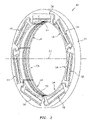
- the seal base 52 is configured as an annular full hoop body (see FIG. 2 ), which extends circumferentially around the axis 22.
- the seal base 52 is configured to circumscribe and support the seal shoes 54 as well as the spring elements 56.
- the seal base 52 extends axially along the axis 22 between and forms the first end surface 46 and the second end surface 50.
- the seal base 52 extends radially between an inner radial base side 58 and an outer radial base side 60.
- the outer radial base side 60 radially engages (e.g., is press fit against) the stationary structure 24 and, more particularly, the seal carrier surface 34 (see FIG. 1 ).
- the seal shoes 54 are configured as arcuate bodies and arranged circumferentially about the axis 22 in an annular array. This annular array of the seal shoes 54 extends circumferentially around the axis 22, thereby forming an inner bore at an inner radial side 62 of the primary seal device 40. As best seen in FIG. 1 , the inner bore is sized to receive the seal land 36, where the rotor structure 26 projects axially through (or into) the inner bore formed by the seal shoes 54.
- each of the seal shoes 54 extends radially from the inner radial side 62 of the primary seal device 40 to an outer radial surface 64 of that seal shoe 54.
- Each of the seal shoes 54 extends circumferentially around the axis 22 between opposing first and second circumferential sides 66 and 68 of that seal shoe 54.
- each of the seal shoes 54 extends axially along the axis 22 between a first shoe end 70 and a second shoe end 72.
- the first shoe end 70 may be axially offset from and project axially away from the first end surface 46.
- the second shoe end 72 may be axially aligned with the second end surface 50.
- the seal shoes 54 of the present disclosure are not limited to such exemplary relationships.
- Each of the seal shoes 54 includes an arcuate end surface generally at (e.g., on, adjacent or proximate) the first shoe end 70. In the array, these arcuate end surfaces collectively form a generally annular (but circumferentially segmented) end surface 74 configured for sealingly engaging with the secondary seal devices 42; see FIG. 1 .
- the seal shoes 54 of the present disclosure are not limited to the foregoing exemplary configuration.
- Each of the seal shoes 54 includes one or more arcuate protrusions, which collectively form one or more (e.g., a plurality of axially spaced) generally annular (e.g., circumferentially segmented) ribs 76 at the inner radial side 62. Distal inner radial ends of one or more of these ribs 76 are configured to be arranged in close proximity with (but not touch) and thereby sealingly mate with the seal land surface 38 in a non-contact manner (see FIG. 1 ), where the rotor structure 26 projects axially through (or into) the inner bore formed by the seal shoes 54.
- each of the ribs 76 has the same radial height. In other embodiments, however, one or more of the ribs 76 may have a different radial height than at least another one of the ribs 76.
- the spring elements 56 are arranged circumferentially about the axis 22 in an annular array. Referring again to FIGS. 3 and 4 , the spring elements 56 are also arranged radially between the seal shoes 54 and the seal base 52. Each of the spring elements 56 is configured to moveably and resiliently connect a respective one of the seal shoes 54 to the seal base 52.
- the spring element 56 of FIG. 4 includes first and second mounts 78 and 80 (e.g., radial fingers / projections) and one or more spring beams 82.
- the first mount 78 is connected to a respective one of the seal shoes 54 at (e.g., on, adjacent or proximate) the first circumferential side 66, where the opposing second circumferential side 68 of that seal shoe 54 is free floating.
- the first mount 78 of FIG. 5 includes a first mount base 84 and a first mount lip 86.
- the first mount base 84 projects radially out from the respective seal shoe 54 to a distal radial outer surface 88 of the first mount 78.
- the first mount base 84 is disposed circumferentially between the spring beams 82 and the first mount lip 86.
- the first mount lip 86 projects laterally (e.g., circumferentially or tangentially) out from the first mount base 84.
- the first mount lip 86 extends radially inward from the outer surface 88 to a radial inner surface 90 of the first mount 78.
- each surface 88, 90 is configured to restrict (e.g., limit) radial movement of the respective seal shoe 54 proximate the first mount 78.
- interaction e.g., contact
- another feature such as the resilient biasing element 57 (or alternatively the surface of the seal base 52) will restrict how far the respective seal shoe 54 can move radially outward.
- interaction e.g., contact
- interaction between the inner surface 90 and another feature such as a radially outer surface 92 of the second mount 80 of an adjacent spring element 56 will restrict how far the respective seal shoe 54 can move radially inward.
- the second mount 80 is connected to the seal base 52, and is generally circumferentially aligned with or near the second circumferential side 68.
- the second mount 80 therefore is disposed a circumferential distance from the first mount 78.
- the second mount 80 of FIG. 5 includes a second mount base 94, a second mount flange 96 and one or more second mount lips 98 and 100.
- the second mount base 94 projects radially inward from the seal base 52 to a radial inner surface 102.
- the second mount flange 96 is laterally adjacent the inner surface 102.
- the second mount flange 96 projects radially inwards from the seal base 52 to a distal radial inner surface 104 of the second mount 80.
- the second mount flange 96 is disposed laterally between the second mount lips 98 and 100.
- the second mount lip 98 projects laterally out from the second mount flange 96.
- the second mount lip 98 extends radially outward from the inner surface 104 to a radial outer surface 106 of the second mount 80.
- the second mount lip 100 projects laterally out from the second mount flange 96.
- the second mount lip 100 extends radially outward from the inner surface 104 to the outer surface 92 of the second mount 80.
- the outer surface 106 and the inner surface 102 are configured as stops for the respective seal shoe 54. More particularly, each surface 106, 102 is configured to restrict (e.g., limit) radial movement of the respective seal shoe 54 proximate the second mount 80. For example, interaction (e.g., contact) between the outer surface 106 and another feature such as a radial inner surface 108 of a lipped flange 109 of the respective seal shoe 54 will restrict how far the respective seal shoe 54 can move radially inward. Similarly, interaction (e.g., contact) between the inner surface 102 and another feature such as a radial outer surface 110 of the lipped flange 109 will restrict how far the respective seal shoe 54 can move radially outward.
- the spring beams 82 are configured as resilient biasing members of the primary seal device 40.
- the spring beams 82 of FIG. 4 are generally configured as cantilevered-leaf springs. These spring beams 82 are radially stacked and spaced apart with one another so as to form a four bar linkage with the first mount 78 and the second mount 80. More particularly, each of the spring beams 82 is connected to the first mount 78 and the second mount 80. Each of the spring beams 82 extends longitudinally (e.g., in a generally circumferential direction relative to the axis 22) between and to the first mount 78 and the second mount 80. The spring beams 82 of FIG. 4 may thereby laterally overlap a major circumferential portion (e.g., ⁇ 65-95%) of the respective seal shoe 54.
- a major circumferential portion e.g., ⁇ 65-95%) of the respective seal shoe 54.
- the spring beams 82 are configured to provide the respective spring element 56 with a certain spring stiffness. This spring stiffness is selected in order to reduce internal stress within the spring beams 82 while also providing the respective spring element 56 with a relatively high natural frequency. However, reducing internal spring beam stress may lower the natural frequency of the respective spring element 56. Therefore, in order to enable relatively low spring beam stress, the resilient biasing elements 57 are provided.
- Each resilient biasing element 57 is configured to enhance (e.g., increase) the spring stiffness of the respective spring element 56 by biasing a first portion 111 of the respective seal shoe 54 radially inward and away from the seal base 52, where the first portion 111 is generally circumferentially aligned with the element 57.
- This resilient biasing element 57 also biases a second portion 113 of the respective seal shoe 54 radially outward and towards the seal base 52, where the second portion 113 is circumferentially offset from the element 57.
- Each resilient biasing element 57 is also configured to provide support for the first circumferential side 66 of that seal shoe 54.
- one or more of the spring beams 82 may be configured with a lower natural frequency in order to lower the internal stresses thereof since the additional spring stiffness provided by the resilient biasing element 57 may effectively make up for a stress-reduction change to the spring beams 82.
- Inclusion of the resilient biasing elements 57 may also enable formation of the spring beams 82 from less stiff materials, which may decrease primary seal device 40 manufacturing costs.
- Each of the resilient biasing elements 57 may be configured as a spring.
- the resilient biasing element 57 of FIG. 6 is configured as a coil spring.
- the resilient biasing element 57 may be configured as another type of spring (e.g., a leaf spring) or another type of resilient biasing device.
- the resilient biasing element 57 of FIGS. 5 and 6 is disposed radially between the first mount 78 and the seal base 52. More particularly, the resilient biasing element 57 extends radially between and radially engages (e.g., contacts, is abutted against) the outer surface 88 and the surface 58 of the seal base 52. However, in other embodiments, the resilient biasing element 57 may be arranged elsewhere with the primary seal device 40. For example, referring to FIG. 7 , the resilient biasing element 57 may be disposed radially between and engage the surfaces 90 and 92. In another example, referring to FIG. 8 , the resilient biasing element 57 may be disposed radially between and engage the surfaces 102 and 110. In still another example, referring to FIG.
- the resilient biasing element 57 may be disposed radially between and engage the surfaces 106 and 108.
- the primary seal device 40 may include one or more additional sets of the resilient biasing elements 57 such that an element 57 can be arranged at all (or some combination) of the locations shown in FIGS. 6-9 and/or other locations.
- rotation of the rotor structure 26 may develop aerodynamic forces and apply a fluid pressure to the seal shoes 54 causing each seal shoe 54 to respectively move radially relative to the seal land surface 38.
- the fluid velocity may increase as a gap between a respective seal shoe 54 and the seal land surface 38 increases, thus reducing pressure in the gap and drawing the seal shoe 54 radially inwardly toward the seal land surface 38.
- the velocity may decrease and the pressure may increase within the gap, thus, forcing the seal shoe 54 radially outwardly from the seal land surface 38.
- the respective spring element 56 may deflect and move with the seal shoe 54 to enable provision of a primary seal of the gap between the seal land surface 38 and ribs 76 within predetermined design tolerances.
- While the primary seal device 40 described above is operable to generally seal the annular gap 30 between the stationary structure 24 and the rotor structure 26, fluid (e.g., gas) may still flow axially through passages 112 defined by the radial air gaps between the elements 52, 54 and 82.
- the secondary seal devices 42 therefore are provided to seal off these passages 112 and, thereby, further and more completely seal the annular gap 30.
- Each of the secondary seal devices 42 may be configured as a ring seal element such as, but not limited to, a split ring. Alternatively, one or more of the secondary seal devices 42 may be configured as a full hoop body ring, an annular brush seal or any other suitable ringtype seal.
- the secondary seal devices 42 of FIG. 1 are arranged together in an axial stack. In this stack, each of the secondary seal devices 42 axially engages (e.g., contacts) another adjacent one of the secondary seal devices 42.
- the stack of the secondary seal devices 42 is arranged with the first ring structure 44, which positions and mounts the secondary seal devices 42 with the stationary structure 24 adjacent the primary seal device 40. In this arrangement, the stack of the secondary seal devices 42 is operable to axially engage and form a seal between the end surface 74 of the array of the seal shoes 54 and an annular surface 114 of the first ring structure 44.
- the first ring structure 44 may include a secondary seal device support ring 116 and a retention ring 118.
- the support ring 116 is configured with an annular full hoop body, which extends circumferentially around the axis 22.
- the support ring 116 includes the annular surface, and is disposed axially adjacent and engaged with the seal base 52.
- the retention ring 118 is configured with an annular full hoop body, which extends circumferentially around the axis 22.
- the retention ring 118 is disposed axially adjacent and engaged with the support ring 116, thereby capturing the stack of the secondary seal devices 42 within an annular channel formed between the rings 116 and 118.
- the stack of the secondary seal devices 42 may also or alternatively be attached to one of the rings 116, 118 by, for example, a press fit connection and/or otherwise.
- FIG. 10 illustrates one such type and configuration of the rotational equipment - a geared turbofan gas turbine engine 120.
- a turbine engine includes various stationary structures (e.g., bearing supports, hubs, cases, etc.) as well as various rotors (e.g., rotor disks, shafts, shaft assemblies, etc.) as described below, where the stationary structure 24 and the rotor structure 26 can respectively be configured as anyone of the foregoing structures in the turbine engine 120 of FIG. 10 , or other structures not mentioned herein.
- the turbine engine 120 of FIG. 10 extends along an axis (e.g., the axis 22 or rotation) between an upstream airflow inlet 122 and a downstream airflow exhaust 124.
- the turbine engine 120 includes a fan section 126, a compressor section 127, a combustor section 128 and a turbine section 129.
- the compressor section 127 includes a low pressure compressor (LPC) section 127A and a high pressure compressor (HPC) section 127B.
- the turbine section 129 includes a high pressure turbine (HPT) section 129A and a low pressure turbine (LPT) section 129B.
- the engine sections 126-129 are arranged sequentially along the axis 22 within an engine housing 130.
- This housing 130 includes an inner case 132 (e.g., a core case) and an outer case 134 (e.g., a fan case).
- the inner case 132 may house one or more of the engine sections 127-129; e.g., an engine core.
- the outer case 134 may house at least the fan section 126.
- Each of the engine sections 126, 127A, 127B, 129A and 129B includes a respective rotor 136-140.
- Each of these rotors 136-140 includes a plurality of rotor blades arranged circumferentially around and connected to one or more respective rotor disks.
- the rotor blades may be formed integral with or mechanically fastened, welded, brazed, adhered and/or otherwise attached to the respective rotor disk(s).
- the fan rotor 136 is connected to a gear train 142, for example, through a fan shaft 144.
- the gear train 142 and the LPC rotor 137 are connected to and driven by the LPT rotor 140 through a low speed shaft 145.
- the HPC rotor 138 is connected to and driven by the HPT rotor 139 through a high speed shaft 146.
- the shafts 144-146 are rotatably supported by a plurality of bearings 148. Each of these bearings 148 is connected to the engine housing 130 by at least one stationary structure 24 such as, for example, an annular support strut.
- This air is directed through the fan section 126 and into a core gas path 150 and a bypass gas path 152.
- the core gas path 150 extends sequentially through the engine sections 127-129; e.g., an engine core.
- the air within the core gas path 150 may be referred to as "core air”.
- the bypass gas path 152 extends through a bypass duct, which bypasses the engine core.
- the air within the bypass gas path 152 may be referred to as "bypass air”.
- the core air is compressed by the compressor rotors 137 and 138 and directed into a combustion chamber 154 of a combustor in the combustor section 128.
- Fuel is injected into the combustion chamber 154 and mixed with the compressed core air to provide a fuel-air mixture.
- This fuel air mixture is ignited and combustion products thereof flow through and sequentially cause the turbine rotors 139 and 140 to rotate.
- the rotation of the turbine rotors 139 and 140 respectively drive rotation of the compressor rotors 138 and 137 and, thus, compression of the air received from a core airflow inlet.
- the rotation of the turbine rotor 140 also drives rotation of the fan rotor 136, which propels bypass air through and out of the bypass gas path 152.
- the propulsion of the bypass air may account for a majority of thrust generated by the turbine engine 120, e.g., more than seventy-five percent (75%) of engine thrust.
- the turbine engine 120 of the present disclosure is not limited to the foregoing exemplary thrust ratio.
- the assembly 20 may be included in various aircraft and industrial turbine engines other than the one described above as well as in other types of rotational equipment; e.g., wind turbines, water turbines, rotary engines, etc.
- the assembly 20, for example, may be included in a geared turbine engine where a gear train connects one or more shafts to one or more rotors in a fan section, a compressor section and/or any other engine section.
- the assembly 20 may be included in a turbine engine configured without a gear train.
- the assembly 20 may be included in a geared or non-geared turbine engine configured with a single spool, with two spools (e.g., see FIG. 10 ), or with more than two spools.
- the turbine engine may be configured as a turbofan engine, a turbojet engine, a propfan engine, a pusher fan engine or any other type of turbine engine.
- the present invention therefore is not limited to any particular types or configurations of turbine engines or rotational equipment.
Description
- This disclosure relates generally to rotational equipment and, more particularly, to a non-contact seal assembly for rotational equipment.
- Rotational equipment such as a gas turbine engine typically includes a seal assembly for sealing an annular gap between a rotor and a stationary structure. Various types and configurations of seal assemblies are known in the art. While these known seal assemblies have various advantages, there is still room in the art for improvement.
-
WO 2014/143284 A1 discloses a prior art assembly according to the preamble of claim 1. -
EP 3 290 756 A1 discloses another prior art assembly. - According to the present disclosure, an assembly is provided for rotational equipment as set forth in claim 1.
- The foregoing features and the operation of the invention will become more apparent in light of the following description and the accompanying drawings.
-
-
FIG. 1 is a partial side sectional illustration of an assembly for rotational equipment. -
FIG. 2 is a perspective illustration of a primary seal device of a non-contact seal assembly. -
FIG. 3 is a partial side sectional illustration of the primary seal device. -
FIG. 4 is an end illustration of a section of the primary seal device. -
FIG. 5 is a segmented end illustration of the primary seal device section ofFIG. 4 . -
FIG. 6 is a perspective illustration of a portion of the primary seal device section ofFIG. 4 . -
FIGS. 7-9 are schematic illustrations of other portions of a primary seal device configured with resilient biasing elements. -
FIG. 10 is a side cutaway illustration of a geared gas turbine engine. -
FIG. 1 illustrates anassembly 20 for rotational equipment with anaxis 22 of rotation; i.e., a rotational axis. An example of such rotational equipment is a gas turbine engine for an aircraft propulsion system, an exemplary embodiment of which is described below in further detail. However, theassembly 20 of the present disclosure is not limited to such an aircraft or gas turbine engine application. Theassembly 20, for example, may alternatively be configured with rotational equipment such as an industrial gas turbine engine, a wind turbine, a water turbine or any other apparatus in which a seal is provided between a stationary structure and a rotor. - The
assembly 20 ofFIG. 1 includes astationary structure 24, arotor structure 26 and anon-contact seal assembly 28. Theseal assembly 28 is mounted with thestationary structure 24 and configured to substantially seal anannular gap 30 between thestationary structure 24 and therotor structure 26 as described below in further detail. - The
stationary structure 24 includes aseal carrier 32. Thisseal carrier 32 may be a discrete, unitary annular body and removably attached to anothercomponent 33 of thestationary structure 24. Alternatively, theseal carrier 32 may be configured with another component / portion of thestationary structure 24; e.g., thecomponents seal carrier 32 has an inner radial seal carrier surface 34. This seal carrier surface 34 may be substantially cylindrical, and extends circumferentially around and faces towards theaxis 22. The seal carrier surface 34 at least partially forms a bore in thestationary structure 24. This bore is sized to receive the seal assembly, which may be fixedly attached to theseal carrier 32 by, for example, a press fit connection between the seal assembly and the seal carrier surface 34. The seal assembly, of course, may also or alternatively be fixedly attached to theseal carrier 32 using one or more other techniques / devices. - The
rotor structure 26 includes aseal land 36. Thisseal land 36 may be a discrete, unitary annular body. Alternatively, theseal land 36 may be configured with another component / portion of therotor structure 26. Theseal land 36 has an outer radialseal land surface 38. Thisseal land surface 38 may be substantially cylindrical, and extends circumferentially around and faces away from theaxis 22. Theseal land surface 38 is disposed to face towards and is axially aligned with the seal carrier surface 34. WhileFIG. 1 illustrates theseal land surface 38 and the seal carrier surface 34 with approximately equal axial lengths along theaxis 22, theseal land surface 38 may alternatively be longer or shorter than the seal carrier surface 34 in other embodiments. - The
seal assembly 28 includes aprimary seal device 40 and one or moresecondary seal devices 42. Theseal assembly 28 also includes one or more additional components for positioning, supporting and/or mounting one or more of the seal devices with thestationary structure 24. Theseal assembly 28 ofFIG. 1 , for example, includes afirst ring structure 44 configured for positioning, supporting and/or mounting thesecondary seal devices 42 relative to theprimary seal device 40. Thisfirst ring structure 44 may also be configured for axially positioning and/or supporting afirst end surface 46 of theprimary seal device 40 relative to thestationary structure 24. Theseal assembly 28 ofFIG. 1 also includes a second ring structure 48 (e.g., a scalloped support ring / plate) configured for axially positioning and/or supporting asecond end surface 50 of theprimary seal device 40 relative to thestationary structure 24. However, thesecond ring structure 48 may be omitted where, for example, thesecond end surface 50 of theprimary seal device 40 is abutted against another component / portion of the stationary structure 24 (e.g., an annular or castellated shoulder) or otherwise axially positioned / secured with thestationary structure 24. - Referring to
FIG. 2 , theprimary seal device 40 is configured as an annular non-contact seal device and, more particularly, a hydrostatic non-contact seal device. An example of such a hydrostatic non-contact seal device is a HALO™ type seal; however, theprimary seal device 40 of the present disclosure is not limited to the foregoing exemplary hydrostatic non-contact seal device. - Referring to
FIG. 3 and4 , theprimary seal device 40 includes aseal base 52, a plurality ofseal shoes 54, a plurality ofspring elements 56. Theprimary seal device 40 also includes a plurality ofresilient biasing elements 57 configured to increase stiffness between theseal shoes 54 and theseal base 52 as described below in further detail. - The
seal base 52 is configured as an annular full hoop body (seeFIG. 2 ), which extends circumferentially around theaxis 22. Theseal base 52 is configured to circumscribe and support theseal shoes 54 as well as thespring elements 56. Theseal base 52 extends axially along theaxis 22 between and forms thefirst end surface 46 and thesecond end surface 50. Theseal base 52 extends radially between an innerradial base side 58 and an outerradial base side 60. The outerradial base side 60 radially engages (e.g., is press fit against) thestationary structure 24 and, more particularly, the seal carrier surface 34 (seeFIG. 1 ). - Referring to
FIG. 2 , theseal shoes 54 are configured as arcuate bodies and arranged circumferentially about theaxis 22 in an annular array. This annular array of theseal shoes 54 extends circumferentially around theaxis 22, thereby forming an inner bore at an innerradial side 62 of theprimary seal device 40. As best seen inFIG. 1 , the inner bore is sized to receive theseal land 36, where therotor structure 26 projects axially through (or into) the inner bore formed by theseal shoes 54. - Referring to
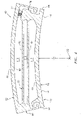
FIG. 4 , each of theseal shoes 54 extends radially from the innerradial side 62 of theprimary seal device 40 to an outerradial surface 64 of thatseal shoe 54. Each of theseal shoes 54 extends circumferentially around theaxis 22 between opposing first and secondcircumferential sides seal shoe 54. - Referring to
FIG. 3 , each of theseal shoes 54 extends axially along theaxis 22 between afirst shoe end 70 and asecond shoe end 72. Thefirst shoe end 70 may be axially offset from and project axially away from thefirst end surface 46. Thesecond shoe end 72 may be axially aligned with thesecond end surface 50. The seal shoes 54 of the present disclosure, however, are not limited to such exemplary relationships. - Each of the seal shoes 54 includes an arcuate end surface generally at (e.g., on, adjacent or proximate) the
first shoe end 70. In the array, these arcuate end surfaces collectively form a generally annular (but circumferentially segmented)end surface 74 configured for sealingly engaging with thesecondary seal devices 42; seeFIG. 1 . The seal shoes 54 of the present disclosure, however, are not limited to the foregoing exemplary configuration. - Each of the seal shoes 54 includes one or more arcuate protrusions, which collectively form one or more (e.g., a plurality of axially spaced) generally annular (e.g., circumferentially segmented)
ribs 76 at the innerradial side 62. Distal inner radial ends of one or more of theseribs 76 are configured to be arranged in close proximity with (but not touch) and thereby sealingly mate with theseal land surface 38 in a non-contact manner (seeFIG. 1 ), where therotor structure 26 projects axially through (or into) the inner bore formed by the seal shoes 54. In the embodiment ofFIG. 3 , each of theribs 76 has the same radial height. In other embodiments, however, one or more of theribs 76 may have a different radial height than at least another one of theribs 76. - Referring to
FIG. 2 , thespring elements 56 are arranged circumferentially about theaxis 22 in an annular array. Referring again toFIGS. 3 and4 , thespring elements 56 are also arranged radially between the seal shoes 54 and theseal base 52. Each of thespring elements 56 is configured to moveably and resiliently connect a respective one of the seal shoes 54 to theseal base 52. - The
spring element 56 ofFIG. 4 includes first andsecond mounts 78 and 80 (e.g., radial fingers / projections) and one or more spring beams 82. Referring toFIG. 5 , thefirst mount 78 is connected to a respective one of the seal shoes 54 at (e.g., on, adjacent or proximate) the firstcircumferential side 66, where the opposing secondcircumferential side 68 of thatseal shoe 54 is free floating. Thefirst mount 78 ofFIG. 5 includes afirst mount base 84 and afirst mount lip 86. Thefirst mount base 84 projects radially out from therespective seal shoe 54 to a distal radialouter surface 88 of thefirst mount 78. Thefirst mount base 84 is disposed circumferentially between the spring beams 82 and thefirst mount lip 86. Thefirst mount lip 86 projects laterally (e.g., circumferentially or tangentially) out from thefirst mount base 84. Thefirst mount lip 86 extends radially inward from theouter surface 88 to a radialinner surface 90 of thefirst mount 78. - The
outer surface 88 and theinner surface 90 are configured as stops for therespective seal shoe 54. More particularly, eachsurface respective seal shoe 54 proximate thefirst mount 78. For example, interaction (e.g., contact) between theouter surface 88 and another feature such as the resilient biasing element 57 (or alternatively the surface of the seal base 52) will restrict how far therespective seal shoe 54 can move radially outward. Similarly, interaction (e.g., contact) between theinner surface 90 and another feature such as a radiallyouter surface 92 of thesecond mount 80 of anadjacent spring element 56 will restrict how far therespective seal shoe 54 can move radially inward. - The
second mount 80 is connected to theseal base 52, and is generally circumferentially aligned with or near the secondcircumferential side 68. Thesecond mount 80 therefore is disposed a circumferential distance from thefirst mount 78. - The
second mount 80 ofFIG. 5 includes asecond mount base 94, asecond mount flange 96 and one or moresecond mount lips second mount base 94 projects radially inward from theseal base 52 to a radialinner surface 102. Thesecond mount flange 96 is laterally adjacent theinner surface 102. Thesecond mount flange 96 projects radially inwards from theseal base 52 to a distal radialinner surface 104 of thesecond mount 80. Thesecond mount flange 96 is disposed laterally between thesecond mount lips second mount lip 98 projects laterally out from thesecond mount flange 96. Thesecond mount lip 98 extends radially outward from theinner surface 104 to a radialouter surface 106 of thesecond mount 80. Thesecond mount lip 100 projects laterally out from thesecond mount flange 96. Thesecond mount lip 100 extends radially outward from theinner surface 104 to theouter surface 92 of thesecond mount 80. - The
outer surface 106 and theinner surface 102 are configured as stops for therespective seal shoe 54. More particularly, eachsurface respective seal shoe 54 proximate thesecond mount 80. For example, interaction (e.g., contact) between theouter surface 106 and another feature such as a radialinner surface 108 of alipped flange 109 of therespective seal shoe 54 will restrict how far therespective seal shoe 54 can move radially inward. Similarly, interaction (e.g., contact) between theinner surface 102 and another feature such as a radialouter surface 110 of thelipped flange 109 will restrict how far therespective seal shoe 54 can move radially outward. - The spring beams 82 are configured as resilient biasing members of the
primary seal device 40. The spring beams 82 ofFIG. 4 , for example, are generally configured as cantilevered-leaf springs. These spring beams 82 are radially stacked and spaced apart with one another so as to form a four bar linkage with thefirst mount 78 and thesecond mount 80. More particularly, each of the spring beams 82 is connected to thefirst mount 78 and thesecond mount 80. Each of the spring beams 82 extends longitudinally (e.g., in a generally circumferential direction relative to the axis 22) between and to thefirst mount 78 and thesecond mount 80. The spring beams 82 ofFIG. 4 may thereby laterally overlap a major circumferential portion (e.g., ~65-95%) of therespective seal shoe 54. - The spring beams 82 are configured to provide the
respective spring element 56 with a certain spring stiffness. This spring stiffness is selected in order to reduce internal stress within the spring beams 82 while also providing therespective spring element 56 with a relatively high natural frequency. However, reducing internal spring beam stress may lower the natural frequency of therespective spring element 56. Therefore, in order to enable relatively low spring beam stress, theresilient biasing elements 57 are provided. - Each resilient biasing
element 57 is configured to enhance (e.g., increase) the spring stiffness of therespective spring element 56 by biasing afirst portion 111 of therespective seal shoe 54 radially inward and away from theseal base 52, where thefirst portion 111 is generally circumferentially aligned with theelement 57. This resilient biasingelement 57 also biases asecond portion 113 of therespective seal shoe 54 radially outward and towards theseal base 52, where thesecond portion 113 is circumferentially offset from theelement 57. Each resilient biasingelement 57 is also configured to provide support for the firstcircumferential side 66 of thatseal shoe 54. As a result, one or more of the spring beams 82 may be configured with a lower natural frequency in order to lower the internal stresses thereof since the additional spring stiffness provided by theresilient biasing element 57 may effectively make up for a stress-reduction change to the spring beams 82. Inclusion of theresilient biasing elements 57 may also enable formation of the spring beams 82 from less stiff materials, which may decreaseprimary seal device 40 manufacturing costs. - Each of the
resilient biasing elements 57 may be configured as a spring. For example, theresilient biasing element 57 ofFIG. 6 is configured as a coil spring. However, in other embodiments, theresilient biasing element 57 may be configured as another type of spring (e.g., a leaf spring) or another type of resilient biasing device. - The
resilient biasing element 57 ofFIGS. 5 and6 is disposed radially between thefirst mount 78 and theseal base 52. More particularly, theresilient biasing element 57 extends radially between and radially engages (e.g., contacts, is abutted against) theouter surface 88 and thesurface 58 of theseal base 52. However, in other embodiments, theresilient biasing element 57 may be arranged elsewhere with theprimary seal device 40. For example, referring toFIG. 7 , theresilient biasing element 57 may be disposed radially between and engage thesurfaces FIG. 8 , theresilient biasing element 57 may be disposed radially between and engage thesurfaces FIG. 9 , theresilient biasing element 57 may be disposed radially between and engage thesurfaces primary seal device 40 may include one or more additional sets of theresilient biasing elements 57 such that anelement 57 can be arranged at all (or some combination) of the locations shown inFIGS. 6-9 and/or other locations. - Referring again to
FIG. 1 , during operation of theprimary seal device 40, rotation of therotor structure 26 may develop aerodynamic forces and apply a fluid pressure to the seal shoes 54 causing eachseal shoe 54 to respectively move radially relative to theseal land surface 38. The fluid velocity may increase as a gap between arespective seal shoe 54 and theseal land surface 38 increases, thus reducing pressure in the gap and drawing theseal shoe 54 radially inwardly toward theseal land surface 38. As the gap closes, the velocity may decrease and the pressure may increase within the gap, thus, forcing theseal shoe 54 radially outwardly from theseal land surface 38. Therespective spring element 56 may deflect and move with theseal shoe 54 to enable provision of a primary seal of the gap between theseal land surface 38 andribs 76 within predetermined design tolerances. - While the
primary seal device 40 described above is operable to generally seal theannular gap 30 between thestationary structure 24 and therotor structure 26, fluid (e.g., gas) may still flow axially throughpassages 112 defined by the radial air gaps between theelements secondary seal devices 42 therefore are provided to seal off thesepassages 112 and, thereby, further and more completely seal theannular gap 30. - Each of the
secondary seal devices 42 may be configured as a ring seal element such as, but not limited to, a split ring. Alternatively, one or more of thesecondary seal devices 42 may be configured as a full hoop body ring, an annular brush seal or any other suitable ringtype seal. - The
secondary seal devices 42 ofFIG. 1 are arranged together in an axial stack. In this stack, each of thesecondary seal devices 42 axially engages (e.g., contacts) another adjacent one of thesecondary seal devices 42. The stack of thesecondary seal devices 42 is arranged with thefirst ring structure 44, which positions and mounts thesecondary seal devices 42 with thestationary structure 24 adjacent theprimary seal device 40. In this arrangement, the stack of thesecondary seal devices 42 is operable to axially engage and form a seal between theend surface 74 of the array of the seal shoes 54 and anannular surface 114 of thefirst ring structure 44. Thesesurfaces secondary seal devices 42 to slide radially against, but maintain sealingly engagement with, theend surface 74 as the seal shoes 54 move radially relative to theseal land surface 38 as described above. - The
first ring structure 44 may include a secondary sealdevice support ring 116 and aretention ring 118. Thesupport ring 116 is configured with an annular full hoop body, which extends circumferentially around theaxis 22. Thesupport ring 116 includes the annular surface, and is disposed axially adjacent and engaged with theseal base 52. - The
retention ring 118 is configured with an annular full hoop body, which extends circumferentially around theaxis 22. Theretention ring 118 is disposed axially adjacent and engaged with thesupport ring 116, thereby capturing the stack of thesecondary seal devices 42 within an annular channel formed between therings secondary seal devices 42, of course, may also or alternatively be attached to one of therings - As described above, the
assembly 20 of the present disclosure may be configured with various different types and configurations of rotational equipment.FIG. 10 illustrates one such type and configuration of the rotational equipment - a geared turbofangas turbine engine 120. Such a turbine engine includes various stationary structures (e.g., bearing supports, hubs, cases, etc.) as well as various rotors (e.g., rotor disks, shafts, shaft assemblies, etc.) as described below, where thestationary structure 24 and therotor structure 26 can respectively be configured as anyone of the foregoing structures in theturbine engine 120 ofFIG. 10 , or other structures not mentioned herein. - The
turbine engine 120 ofFIG. 10 extends along an axis (e.g., theaxis 22 or rotation) between anupstream airflow inlet 122 and adownstream airflow exhaust 124. Theturbine engine 120 includes afan section 126, acompressor section 127, acombustor section 128 and aturbine section 129. Thecompressor section 127 includes a low pressure compressor (LPC)section 127A and a high pressure compressor (HPC)section 127B. Theturbine section 129 includes a high pressure turbine (HPT)section 129A and a low pressure turbine (LPT)section 129B. - The engine sections 126-129 are arranged sequentially along the
axis 22 within anengine housing 130. Thishousing 130 includes an inner case 132 (e.g., a core case) and an outer case 134 (e.g., a fan case). The inner case 132 may house one or more of the engine sections 127-129; e.g., an engine core. Theouter case 134 may house at least thefan section 126. - Each of the
engine sections - The
fan rotor 136 is connected to agear train 142, for example, through afan shaft 144. Thegear train 142 and theLPC rotor 137 are connected to and driven by theLPT rotor 140 through alow speed shaft 145. TheHPC rotor 138 is connected to and driven by theHPT rotor 139 through ahigh speed shaft 146. The shafts 144-146 are rotatably supported by a plurality ofbearings 148. Each of thesebearings 148 is connected to theengine housing 130 by at least onestationary structure 24 such as, for example, an annular support strut. - During operation, air enters the
turbine engine 120 through theairflow inlet 122. This air is directed through thefan section 126 and into acore gas path 150 and abypass gas path 152. Thecore gas path 150 extends sequentially through the engine sections 127-129; e.g., an engine core. The air within thecore gas path 150 may be referred to as "core air". Thebypass gas path 152 extends through a bypass duct, which bypasses the engine core. The air within thebypass gas path 152 may be referred to as "bypass air". - The core air is compressed by the
compressor rotors combustion chamber 154 of a combustor in thecombustor section 128. Fuel is injected into thecombustion chamber 154 and mixed with the compressed core air to provide a fuel-air mixture. This fuel air mixture is ignited and combustion products thereof flow through and sequentially cause theturbine rotors turbine rotors compressor rotors turbine rotor 140 also drives rotation of thefan rotor 136, which propels bypass air through and out of thebypass gas path 152. The propulsion of the bypass air may account for a majority of thrust generated by theturbine engine 120, e.g., more than seventy-five percent (75%) of engine thrust. Theturbine engine 120 of the present disclosure, however, is not limited to the foregoing exemplary thrust ratio. - The
assembly 20 may be included in various aircraft and industrial turbine engines other than the one described above as well as in other types of rotational equipment; e.g., wind turbines, water turbines, rotary engines, etc. Theassembly 20, for example, may be included in a geared turbine engine where a gear train connects one or more shafts to one or more rotors in a fan section, a compressor section and/or any other engine section. Alternatively, theassembly 20 may be included in a turbine engine configured without a gear train. Theassembly 20 may be included in a geared or non-geared turbine engine configured with a single spool, with two spools (e.g., seeFIG. 10 ), or with more than two spools. The turbine engine may be configured as a turbofan engine, a turbojet engine, a propfan engine, a pusher fan engine or any other type of turbine engine. The present invention therefore is not limited to any particular types or configurations of turbine engines or rotational equipment. - While various embodiments of the present invention have been disclosed, it will be apparent to those of ordinary skill in the art that many more embodiments and implementations are possible within the scope of the claims.
Claims (15)
- An assembly (20) for rotational equipment, comprising:a seal device (40) comprising a plurality of seal shoes (54), a seal base (52), a plurality of spring elements (56) and a resilient biasing element (57);the seal shoes (54) arranged around an axis (22) in an annular array;the seal base (52) circumscribing the annular array of the seal shoes (54);each of the spring elements (56) radially between and connecting a respective one of the seal shoes (54) and the seal base (52), a first of the spring elements (56) including a first mount (78), a second mount (80) and a spring beam (82), the first mount (78) connected to a first of the seal shoes (54), the second mount (80) connected to the seal base (52), and the spring beam (82) connecting the first mount (78) to the second mount (80); andthe resilient biasing element (57) radially between and engaged with first and second components of the seal device (40), the first component comprising the first mount (78) or the second mount (80);characterised in that:
the resilient biasing element (57) comprises a coil spring. - The assembly (20) of claim 1, wherein the resilient biasing element (57) is configured to increase a stiffness of the first of the spring elements (56).
- The assembly (20) of claim 1 or 2, wherein the resilient biasing element (57) is configured to bias a first portion (111) of the first of the seal shoes (54) radially away from the seal base (52) and a second portion (113) of the first of the seal shoes (54) radially towards the seal base (52).
- The assembly (20) of any preceding claim, whereinthe first component comprises the first mount (78); andthe second component comprises the seal base (52).
- The assembly (20) of any of claims 1 to 3, whereinthe first component comprises the first mount (78); andthe second component comprises a mount (80) of a second of the spring elements (56) that is circumferentially adjacent to the first of the spring elements (56).
- The assembly (20) of claim 5, whereinthe first mount (78) comprises an inner surface (90);the mount (80) of the second of the spring elements (56) comprises an outer surface (92) radially below the inner surface (90); andthe resilient biasing element (57) is radially between and engages the inner surface (90) and the outer surface (92).
- The assembly (20) of claim 5, whereinthe mount (80) of the second of the spring elements (56) comprises a second mount (80);the second of the spring elements (56) further includes a first mount (78) and a spring beam (82);the first mount (78) of the second of the spring elements (56) is connected to a second of the seal shoes (54);the second mount (80) of the second of the spring elements (56) is connected to the seal base (52); andthe spring beam (82) of the second of the spring elements (56) connects the first mount (78) of the second of the spring elements (56) to the second mount (80) of the second of the spring elements (56).
- The assembly (20) of any of claims 1 to 3, whereinthe first component comprises the second mount (80); andthe second component comprises the first of the seal shoes (54).
- The assembly (20) of claim 8, wherein:the second mount (80) comprises an inner surface (102), the first of the seal shoes (54) comprises an outer surface (110) radially below the inner surface (102), and the resilient biasing element (57) is radially between and engages the inner surface (102) and the outer surface (110); orthe first of the seal shoes (54) comprises an inner surface (108), the second mount (80) comprises an outer surface (106) radially below the inner surface (108), and the resilient biasing element (57) is radially between and engages the inner surface (108) and the outer surface (106).
- The assembly (20) of any of claims 1 to 3, wherein:the first component comprises the first mount (78), and the seal device (40) further includes a second resilient biasing element (57) engaged with the second mount (80); orthe seal device (40) further includes a second resilient biasing element (57) engaged with the first component.
- The assembly (20) of any preceding claim, wherein the first of the spring elements (56) further includes a second spring beam (82) connecting the first mount (78) to the second mount (80).
- The assembly (20) of any preceding claim, further comprising:a ring structure (44) axially engaged with the seal base (52); anda secondary seal device (42) mounted with the ring structure (44), the secondary seal device (42) configured to substantially seal an annular gap between the ring structure (44) and the annular array of the seal shoes (54).
- The assembly (20) of any preceding claim, further comprising:a stationary structure (24);a rotor structure (26); anda non-contact seal assembly (28) comprising the seal device (40), the seal assembly (28) configured to substantially seal an annular gap (30) between the stationary structure (24) and the rotor structure (26);wherein the seal shoes (54) circumscribe and sealingly mate with the rotor structure (26); andwherein the seal base (52) is mounted to and radially within the stationary structure (24).
- The assembly (20) of claim 1, wherein the seal base (52) extends circumferentially around the seal shoes (54) and the spring elements (56), the first of the spring elements (56) includes a plurality of spring beams (82), each of the spring beams (82) connects the first mount (78) to the second mount (80), and the spring (57) is abutted against first and second components of the seal device (40).
- The assembly (20) of claim 14, wherein the spring (57) is configured to increase a stiffness of the first of the spring elements (56).
Applications Claiming Priority (1)
| Application Number | Priority Date | Filing Date | Title |
|---|---|---|---|
| US15/653,020 US10184347B1 (en) | 2017-07-18 | 2017-07-18 | Non-contact seal with resilient biasing element(s) |
Publications (2)
| Publication Number | Publication Date |
|---|---|
| EP3431838A1 EP3431838A1 (en) | 2019-01-23 |
| EP3431838B1 true EP3431838B1 (en) | 2022-06-29 |
Family
ID=62217893
Family Applications (1)
| Application Number | Title | Priority Date | Filing Date |
|---|---|---|---|
| EP18173373.4A Active EP3431838B1 (en) | 2017-07-18 | 2018-05-18 | Non-contact seal with resilient biasing element(s) |
Country Status (2)
| Country | Link |
|---|---|
| US (2) | US10184347B1 (en) |
| EP (1) | EP3431838B1 (en) |
Families Citing this family (17)
| Publication number | Priority date | Publication date | Assignee | Title |
|---|---|---|---|---|
| US10184347B1 (en) * | 2017-07-18 | 2019-01-22 | United Technologies Corporation | Non-contact seal with resilient biasing element(s) |
| US10746039B2 (en) * | 2017-09-25 | 2020-08-18 | United Technologies Corporation | Hydrostatic seal pinned cartridge |
| US10626744B2 (en) * | 2017-09-29 | 2020-04-21 | United Technologies Corporation | Dual hydorstatic seal assembly |
| US10731496B2 (en) * | 2018-01-17 | 2020-08-04 | Raytheon Technologies Corporation | Bearing-supported seal |
| US10822983B2 (en) * | 2018-02-06 | 2020-11-03 | Raytheon Technologies Corportation | Hydrostatic seal with abradable teeth for gas turbine engine |
| US11421543B2 (en) * | 2018-11-28 | 2022-08-23 | Raytheon Technologies Corporation | Hydrostatic seal with asymmetric beams for anti-tipping |
| US11674402B2 (en) | 2018-11-28 | 2023-06-13 | Raytheon Technologies Corporation | Hydrostatic seal with non-parallel beams for anti-tipping |
| US10968763B2 (en) * | 2019-02-01 | 2021-04-06 | Raytheon Technologies Corporation | HALO seal build clearance methods |
| US11434827B2 (en) * | 2019-04-11 | 2022-09-06 | Raytheon Technologies Corporation | Hydrostatic seal with secondary seal structural protection |
| EP3990808A1 (en) * | 2019-07-30 | 2022-05-04 | Siemens Energy Global GmbH & Co. KG | Non-contact seal assembly with damping elements |
| US11415227B2 (en) | 2019-08-21 | 2022-08-16 | Raytheon Technologies Corporation | Non-contact seal assembly with chamfered seal shoe |
| US11493135B2 (en) * | 2019-08-23 | 2022-11-08 | Raytheon Technologies Corporation | Non-contact seal with axial engagement |
| US20210062669A1 (en) * | 2019-08-26 | 2021-03-04 | United Technologies Corporation | Hydrostatic seal with seal stops |
| US11193593B2 (en) | 2019-09-03 | 2021-12-07 | Raytheon Technologies Corporation | Hydrostatic seal |
| CN114616126A (en) | 2019-11-07 | 2022-06-10 | 泰加汽车股份有限公司 | Thermal management system for electric vehicle |
| US11359726B2 (en) * | 2020-07-02 | 2022-06-14 | Raytheon Technologies Corporation | Non-contact seal assembly with multiple axially spaced spring elements |
| US20220268166A1 (en) * | 2021-02-19 | 2022-08-25 | Raytheon Technologies Corporation | Non-contacting seal assembly with internal coating |
Family Cites Families (34)
| Publication number | Priority date | Publication date | Assignee | Title |
|---|---|---|---|---|
| US6428009B2 (en) | 2000-04-03 | 2002-08-06 | John F. Justak | Robust hydrodynamic brush seal |
| US8641045B2 (en) * | 2003-05-01 | 2014-02-04 | Advanced Technologies Group, Inc. | Seal with stacked sealing elements |
| US7410173B2 (en) * | 2003-05-01 | 2008-08-12 | Justak John F | Hydrodynamic brush seal |
| US8172232B2 (en) * | 2003-05-01 | 2012-05-08 | Advanced Technologies Group, Inc. | Non-contact seal for a gas turbine engine |
| US7896352B2 (en) * | 2003-05-01 | 2011-03-01 | Justak John F | Seal with stacked sealing elements |
| US8002285B2 (en) * | 2003-05-01 | 2011-08-23 | Justak John F | Non-contact seal for a gas turbine engine |
| US20040217549A1 (en) | 2003-05-01 | 2004-11-04 | Justak John F. | Hydrodynamic brush seal |
| US8919781B2 (en) * | 2003-05-01 | 2014-12-30 | Advanced Technologies Group, Inc. | Self-adjusting non-contact seal |
| US8820752B2 (en) | 2008-09-15 | 2014-09-02 | Stein Seal Company | Intershaft seal with centrifugal compensation |
| US8740225B2 (en) * | 2009-06-03 | 2014-06-03 | Exponential Technologies, Inc. | Hydrodynamic bore seal |
| WO2010146797A1 (en) | 2009-06-16 | 2010-12-23 | 三菱重工業株式会社 | Shaft seal device |
| US9145785B2 (en) * | 2011-03-04 | 2015-09-29 | General Electric Company | Aerodynamic seal assemblies for turbo-machinery |
| US9255642B2 (en) * | 2012-07-06 | 2016-02-09 | General Electric Company | Aerodynamic seals for rotary machine |
| US9587746B2 (en) * | 2012-07-31 | 2017-03-07 | General Electric Company | Film riding seals for rotary machines |
| US9115810B2 (en) | 2012-10-31 | 2015-08-25 | General Electric Company | Pressure actuated film riding seals for turbo machinery |
| US10119474B2 (en) * | 2013-03-15 | 2018-11-06 | United Technologies Corporation | Vibration damping apparatus for hydrostatic seal of gas turbine engine |
| WO2015147967A1 (en) * | 2014-03-27 | 2015-10-01 | United Technologies Corporation | Gas turbine engine and seal assembly therefore |
| US20150285152A1 (en) * | 2014-04-03 | 2015-10-08 | United Technologies Corporation | Gas turbine engine and seal assembly therefore |
| US10801348B2 (en) | 2014-10-14 | 2020-10-13 | Raytheon Technologies Corporation | Non-contacting dynamic seal |
| US9988921B2 (en) * | 2014-10-17 | 2018-06-05 | United Technologies Corporation | Circumferential seal with seal dampening elements |
| US10370991B2 (en) * | 2014-11-07 | 2019-08-06 | United Technologies Corporation | Gas turbine engine and seal assembly therefore |
| US10794208B2 (en) * | 2015-07-08 | 2020-10-06 | Raytheon Technologies Corporation | Non-contact seal assembly for rotational equipment with linkage between adjacent rotors |
| US10107126B2 (en) * | 2015-08-19 | 2018-10-23 | United Technologies Corporation | Non-contact seal assembly for rotational equipment |
| US10094241B2 (en) * | 2015-08-19 | 2018-10-09 | United Technologies Corporation | Non-contact seal assembly for rotational equipment |
| US20170051751A1 (en) * | 2015-08-19 | 2017-02-23 | United Technologies Corporation | Seal assembly for rotational equipment |
| US10030531B2 (en) * | 2016-01-22 | 2018-07-24 | United Technologies Corporation | Seal shoe for a hydrostatic non-contact seal device |
| US10221714B2 (en) * | 2016-01-22 | 2019-03-05 | United Technologies Corporation | Secondary seal device(s) with alignment tab(s) |
| US10428672B2 (en) * | 2016-02-08 | 2019-10-01 | United Technologies Corporation | Floating, non-contact seal and dimensions thereof |
| US10060535B2 (en) * | 2016-02-25 | 2018-08-28 | United Technologies Corporation | Shaped spring element for a non-contact seal device |
| US10415413B2 (en) * | 2016-09-01 | 2019-09-17 | United Technologies Corporation | Floating non-contact seal vertical lip |
| US10422431B2 (en) * | 2017-07-17 | 2019-09-24 | United Technologies Corporation | Non-contact seal with progressive radial stop(s) |
| US10184347B1 (en) * | 2017-07-18 | 2019-01-22 | United Technologies Corporation | Non-contact seal with resilient biasing element(s) |
| US11047481B2 (en) * | 2017-09-06 | 2021-06-29 | General Electric Company | Seal assembly for a rotary machine |
| US10815809B2 (en) * | 2018-10-02 | 2020-10-27 | Raytheon Technologies Corporation | Guided non-contact seal assembly |
-
2017
- 2017-07-18 US US15/653,020 patent/US10184347B1/en active Active
-
2018
- 2018-05-18 EP EP18173373.4A patent/EP3431838B1/en active Active
-
2019
- 2019-01-14 US US16/246,748 patent/US11021985B2/en active Active
Also Published As
| Publication number | Publication date |
|---|---|
| US10184347B1 (en) | 2019-01-22 |
| US20190024522A1 (en) | 2019-01-24 |
| US20200025006A1 (en) | 2020-01-23 |
| EP3431838A1 (en) | 2019-01-23 |
| US11021985B2 (en) | 2021-06-01 |
Similar Documents
| Publication | Publication Date | Title |
|---|---|---|
| EP3431838B1 (en) | Non-contact seal with resilient biasing element(s) | |
| US10563532B2 (en) | Non-contact seal with monolithic/unitary carrier structure | |
| US10208615B2 (en) | Seal shoe for a hydrostatic non-contact seal device | |
| US10612669B2 (en) | Shaped spring element for a non-contact seal device | |
| US10697550B2 (en) | Non-contact seal with progressive radial stop(s) | |
| US10830081B2 (en) | Non-contact seal with non-straight spring beam(s) | |
| US10961860B2 (en) | Non-contact seal with removal features | |
| US10641180B2 (en) | Hydrostatic non-contact seal with varied thickness beams | |
| US10337621B2 (en) | Hydrostatic non-contact seal with weight reduction pocket | |
| EP3428489B1 (en) | Hydrostatic non-contact seal with seal carrier elimination | |
| EP3428490A1 (en) | Hydrostatic non-contact seal with offset outer ring | |
| EP3961071A1 (en) | Non-contact seal for rotational equipment with axially extended seal shoes |
Legal Events
| Date | Code | Title | Description |
|---|---|---|---|
| PUAI | Public reference made under article 153(3) epc to a published international application that has entered the european phase |
Free format text: ORIGINAL CODE: 0009012 |
|
| STAA | Information on the status of an ep patent application or granted ep patent |
Free format text: STATUS: THE APPLICATION HAS BEEN PUBLISHED |
|
| AK | Designated contracting states |
Kind code of ref document: A1 Designated state(s): AL AT BE BG CH CY CZ DE DK EE ES FI FR GB GR HR HU IE IS IT LI LT LU LV MC MK MT NL NO PL PT RO RS SE SI SK SM TR |
|
| AX | Request for extension of the european patent |
Extension state: BA ME |
|
| STAA | Information on the status of an ep patent application or granted ep patent |
Free format text: STATUS: REQUEST FOR EXAMINATION WAS MADE |
|
| 17P | Request for examination filed |
Effective date: 20190723 |
|
| RBV | Designated contracting states (corrected) |
Designated state(s): AL AT BE BG CH CY CZ DE DK EE ES FI FR GB GR HR HU IE IS IT LI LT LU LV MC MK MT NL NO PL PT RO RS SE SI SK SM TR |
|
| STAA | Information on the status of an ep patent application or granted ep patent |
Free format text: STATUS: EXAMINATION IS IN PROGRESS |
|
| 17Q | First examination report despatched |
Effective date: 20200211 |
|
| STAA | Information on the status of an ep patent application or granted ep patent |
Free format text: STATUS: EXAMINATION IS IN PROGRESS |
|
| RAP1 | Party data changed (applicant data changed or rights of an application transferred) |
Owner name: RAYTHEON TECHNOLOGIES CORPORATION |
|
| GRAP | Despatch of communication of intention to grant a patent |
Free format text: ORIGINAL CODE: EPIDOSNIGR1 |
|
| STAA | Information on the status of an ep patent application or granted ep patent |
Free format text: STATUS: GRANT OF PATENT IS INTENDED |
|
| INTG | Intention to grant announced |
Effective date: 20211221 |
|
| GRAS | Grant fee paid |
Free format text: ORIGINAL CODE: EPIDOSNIGR3 |
|
| GRAA | (expected) grant |
Free format text: ORIGINAL CODE: 0009210 |
|
| STAA | Information on the status of an ep patent application or granted ep patent |
Free format text: STATUS: THE PATENT HAS BEEN GRANTED |
|
| AK | Designated contracting states |
Kind code of ref document: B1 Designated state(s): AL AT BE BG CH CY CZ DE DK EE ES FI FR GB GR HR HU IE IS IT LI LT LU LV MC MK MT NL NO PL PT RO RS SE SI SK SM TR |
|
| REG | Reference to a national code |
Ref country code: CH Ref legal event code: EP |
|
| REG | Reference to a national code |
Ref country code: AT Ref legal event code: REF Ref document number: 1501550 Country of ref document: AT Kind code of ref document: T Effective date: 20220715 |
|
| REG | Reference to a national code |
Ref country code: IE Ref legal event code: FG4D |
|
| REG | Reference to a national code |
Ref country code: DE Ref legal event code: R096 Ref document number: 602018037221 Country of ref document: DE |
|
| REG | Reference to a national code |
Ref country code: LT Ref legal event code: MG9D |
|
| PG25 | Lapsed in a contracting state [announced via postgrant information from national office to epo] |
Ref country code: SE Free format text: LAPSE BECAUSE OF FAILURE TO SUBMIT A TRANSLATION OF THE DESCRIPTION OR TO PAY THE FEE WITHIN THE PRESCRIBED TIME-LIMIT Effective date: 20220629 Ref country code: NO Free format text: LAPSE BECAUSE OF FAILURE TO SUBMIT A TRANSLATION OF THE DESCRIPTION OR TO PAY THE FEE WITHIN THE PRESCRIBED TIME-LIMIT Effective date: 20220929 Ref country code: LT Free format text: LAPSE BECAUSE OF FAILURE TO SUBMIT A TRANSLATION OF THE DESCRIPTION OR TO PAY THE FEE WITHIN THE PRESCRIBED TIME-LIMIT Effective date: 20220629 Ref country code: HR Free format text: LAPSE BECAUSE OF FAILURE TO SUBMIT A TRANSLATION OF THE DESCRIPTION OR TO PAY THE FEE WITHIN THE PRESCRIBED TIME-LIMIT Effective date: 20220629 Ref country code: GR Free format text: LAPSE BECAUSE OF FAILURE TO SUBMIT A TRANSLATION OF THE DESCRIPTION OR TO PAY THE FEE WITHIN THE PRESCRIBED TIME-LIMIT Effective date: 20220930 Ref country code: FI Free format text: LAPSE BECAUSE OF FAILURE TO SUBMIT A TRANSLATION OF THE DESCRIPTION OR TO PAY THE FEE WITHIN THE PRESCRIBED TIME-LIMIT Effective date: 20220629 Ref country code: BG Free format text: LAPSE BECAUSE OF FAILURE TO SUBMIT A TRANSLATION OF THE DESCRIPTION OR TO PAY THE FEE WITHIN THE PRESCRIBED TIME-LIMIT Effective date: 20220929 |
|
| REG | Reference to a national code |
Ref country code: NL Ref legal event code: MP Effective date: 20220629 |
|
| REG | Reference to a national code |
Ref country code: AT Ref legal event code: MK05 Ref document number: 1501550 Country of ref document: AT Kind code of ref document: T Effective date: 20220629 |
|
| PG25 | Lapsed in a contracting state [announced via postgrant information from national office to epo] |
Ref country code: RS Free format text: LAPSE BECAUSE OF FAILURE TO SUBMIT A TRANSLATION OF THE DESCRIPTION OR TO PAY THE FEE WITHIN THE PRESCRIBED TIME-LIMIT Effective date: 20220629 Ref country code: LV Free format text: LAPSE BECAUSE OF FAILURE TO SUBMIT A TRANSLATION OF THE DESCRIPTION OR TO PAY THE FEE WITHIN THE PRESCRIBED TIME-LIMIT Effective date: 20220629 |
|
| PG25 | Lapsed in a contracting state [announced via postgrant information from national office to epo] |
Ref country code: NL Free format text: LAPSE BECAUSE OF FAILURE TO SUBMIT A TRANSLATION OF THE DESCRIPTION OR TO PAY THE FEE WITHIN THE PRESCRIBED TIME-LIMIT Effective date: 20220629 |
|
| PG25 | Lapsed in a contracting state [announced via postgrant information from national office to epo] |
Ref country code: SM Free format text: LAPSE BECAUSE OF FAILURE TO SUBMIT A TRANSLATION OF THE DESCRIPTION OR TO PAY THE FEE WITHIN THE PRESCRIBED TIME-LIMIT Effective date: 20220629 Ref country code: SK Free format text: LAPSE BECAUSE OF FAILURE TO SUBMIT A TRANSLATION OF THE DESCRIPTION OR TO PAY THE FEE WITHIN THE PRESCRIBED TIME-LIMIT Effective date: 20220629 Ref country code: RO Free format text: LAPSE BECAUSE OF FAILURE TO SUBMIT A TRANSLATION OF THE DESCRIPTION OR TO PAY THE FEE WITHIN THE PRESCRIBED TIME-LIMIT Effective date: 20220629 Ref country code: PT Free format text: LAPSE BECAUSE OF FAILURE TO SUBMIT A TRANSLATION OF THE DESCRIPTION OR TO PAY THE FEE WITHIN THE PRESCRIBED TIME-LIMIT Effective date: 20221031 Ref country code: ES Free format text: LAPSE BECAUSE OF FAILURE TO SUBMIT A TRANSLATION OF THE DESCRIPTION OR TO PAY THE FEE WITHIN THE PRESCRIBED TIME-LIMIT Effective date: 20220629 Ref country code: EE Free format text: LAPSE BECAUSE OF FAILURE TO SUBMIT A TRANSLATION OF THE DESCRIPTION OR TO PAY THE FEE WITHIN THE PRESCRIBED TIME-LIMIT Effective date: 20220629 Ref country code: AT Free format text: LAPSE BECAUSE OF FAILURE TO SUBMIT A TRANSLATION OF THE DESCRIPTION OR TO PAY THE FEE WITHIN THE PRESCRIBED TIME-LIMIT Effective date: 20220629 |
|
| PG25 | Lapsed in a contracting state [announced via postgrant information from national office to epo] |
Ref country code: PL Free format text: LAPSE BECAUSE OF FAILURE TO SUBMIT A TRANSLATION OF THE DESCRIPTION OR TO PAY THE FEE WITHIN THE PRESCRIBED TIME-LIMIT Effective date: 20220629 Ref country code: IS Free format text: LAPSE BECAUSE OF FAILURE TO SUBMIT A TRANSLATION OF THE DESCRIPTION OR TO PAY THE FEE WITHIN THE PRESCRIBED TIME-LIMIT Effective date: 20221029 |
|
| REG | Reference to a national code |
Ref country code: DE Ref legal event code: R097 Ref document number: 602018037221 Country of ref document: DE |
|
| PG25 | Lapsed in a contracting state [announced via postgrant information from national office to epo] |
Ref country code: AL Free format text: LAPSE BECAUSE OF FAILURE TO SUBMIT A TRANSLATION OF THE DESCRIPTION OR TO PAY THE FEE WITHIN THE PRESCRIBED TIME-LIMIT Effective date: 20220629 |
|
| PG25 | Lapsed in a contracting state [announced via postgrant information from national office to epo] |
Ref country code: DK Free format text: LAPSE BECAUSE OF FAILURE TO SUBMIT A TRANSLATION OF THE DESCRIPTION OR TO PAY THE FEE WITHIN THE PRESCRIBED TIME-LIMIT Effective date: 20220629 Ref country code: CZ Free format text: LAPSE BECAUSE OF FAILURE TO SUBMIT A TRANSLATION OF THE DESCRIPTION OR TO PAY THE FEE WITHIN THE PRESCRIBED TIME-LIMIT Effective date: 20220629 |
|
| PLBE | No opposition filed within time limit |
Free format text: ORIGINAL CODE: 0009261 |
|
| STAA | Information on the status of an ep patent application or granted ep patent |
Free format text: STATUS: NO OPPOSITION FILED WITHIN TIME LIMIT |
|
| 26N | No opposition filed |
Effective date: 20230330 |
|
| P01 | Opt-out of the competence of the unified patent court (upc) registered |
Effective date: 20230521 |
|
| PGFP | Annual fee paid to national office [announced via postgrant information from national office to epo] |
Ref country code: FR Payment date: 20230420 Year of fee payment: 6 Ref country code: DE Payment date: 20230419 Year of fee payment: 6 |
|
| PG25 | Lapsed in a contracting state [announced via postgrant information from national office to epo] |
Ref country code: SI Free format text: LAPSE BECAUSE OF FAILURE TO SUBMIT A TRANSLATION OF THE DESCRIPTION OR TO PAY THE FEE WITHIN THE PRESCRIBED TIME-LIMIT Effective date: 20220629 |
|
| PGFP | Annual fee paid to national office [announced via postgrant information from national office to epo] |
Ref country code: GB Payment date: 20230420 Year of fee payment: 6 |
|
| REG | Reference to a national code |
Ref country code: CH Ref legal event code: PL |
|
| PG25 | Lapsed in a contracting state [announced via postgrant information from national office to epo] |
Ref country code: MC Free format text: LAPSE BECAUSE OF FAILURE TO SUBMIT A TRANSLATION OF THE DESCRIPTION OR TO PAY THE FEE WITHIN THE PRESCRIBED TIME-LIMIT Effective date: 20220629 |
|
| REG | Reference to a national code |
Ref country code: BE Ref legal event code: MM Effective date: 20230531 |
|
| PG25 | Lapsed in a contracting state [announced via postgrant information from national office to epo] |
Ref country code: MC Free format text: LAPSE BECAUSE OF FAILURE TO SUBMIT A TRANSLATION OF THE DESCRIPTION OR TO PAY THE FEE WITHIN THE PRESCRIBED TIME-LIMIT Effective date: 20220629 Ref country code: LU Free format text: LAPSE BECAUSE OF NON-PAYMENT OF DUE FEES Effective date: 20230518 Ref country code: LI Free format text: LAPSE BECAUSE OF NON-PAYMENT OF DUE FEES Effective date: 20230531 Ref country code: IT Free format text: LAPSE BECAUSE OF FAILURE TO SUBMIT A TRANSLATION OF THE DESCRIPTION OR TO PAY THE FEE WITHIN THE PRESCRIBED TIME-LIMIT Effective date: 20220629 Ref country code: CH Free format text: LAPSE BECAUSE OF NON-PAYMENT OF DUE FEES Effective date: 20230531 |
|
| REG | Reference to a national code |
Ref country code: IE Ref legal event code: MM4A |