EP3428490A1 - Hydrostatic non-contact seal with offset outer ring - Google Patents
Hydrostatic non-contact seal with offset outer ring Download PDFInfo
- Publication number
- EP3428490A1 EP3428490A1 EP18172186.1A EP18172186A EP3428490A1 EP 3428490 A1 EP3428490 A1 EP 3428490A1 EP 18172186 A EP18172186 A EP 18172186A EP 3428490 A1 EP3428490 A1 EP 3428490A1
- Authority
- EP
- European Patent Office
- Prior art keywords
- seal
- assembly
- shoe
- axially
- shoes
- Prior art date
- Legal status (The legal status is an assumption and is not a legal conclusion. Google has not performed a legal analysis and makes no representation as to the accuracy of the status listed.)
- Pending
Links
Images


Classifications
-
- F—MECHANICAL ENGINEERING; LIGHTING; HEATING; WEAPONS; BLASTING
- F16—ENGINEERING ELEMENTS AND UNITS; GENERAL MEASURES FOR PRODUCING AND MAINTAINING EFFECTIVE FUNCTIONING OF MACHINES OR INSTALLATIONS; THERMAL INSULATION IN GENERAL
- F16J—PISTONS; CYLINDERS; SEALINGS
- F16J15/00—Sealings
- F16J15/44—Free-space packings
- F16J15/441—Free-space packings with floating ring
- F16J15/442—Free-space packings with floating ring segmented
-
- F—MECHANICAL ENGINEERING; LIGHTING; HEATING; WEAPONS; BLASTING
- F01—MACHINES OR ENGINES IN GENERAL; ENGINE PLANTS IN GENERAL; STEAM ENGINES
- F01D—NON-POSITIVE DISPLACEMENT MACHINES OR ENGINES, e.g. STEAM TURBINES
- F01D11/00—Preventing or minimising internal leakage of working-fluid, e.g. between stages
- F01D11/02—Preventing or minimising internal leakage of working-fluid, e.g. between stages by non-contact sealings, e.g. of labyrinth type
- F01D11/025—Seal clearance control; Floating assembly; Adaptation means to differential thermal dilatations
-
- F—MECHANICAL ENGINEERING; LIGHTING; HEATING; WEAPONS; BLASTING
- F01—MACHINES OR ENGINES IN GENERAL; ENGINE PLANTS IN GENERAL; STEAM ENGINES
- F01D—NON-POSITIVE DISPLACEMENT MACHINES OR ENGINES, e.g. STEAM TURBINES
- F01D11/00—Preventing or minimising internal leakage of working-fluid, e.g. between stages
- F01D11/08—Preventing or minimising internal leakage of working-fluid, e.g. between stages for sealing space between rotor blade tips and stator
- F01D11/12—Preventing or minimising internal leakage of working-fluid, e.g. between stages for sealing space between rotor blade tips and stator using a rubstrip, e.g. erodible. deformable or resiliently-biased part
-
- F—MECHANICAL ENGINEERING; LIGHTING; HEATING; WEAPONS; BLASTING
- F01—MACHINES OR ENGINES IN GENERAL; ENGINE PLANTS IN GENERAL; STEAM ENGINES
- F01D—NON-POSITIVE DISPLACEMENT MACHINES OR ENGINES, e.g. STEAM TURBINES
- F01D25/00—Component parts, details, or accessories, not provided for in, or of interest apart from, other groups
- F01D25/18—Lubricating arrangements
- F01D25/22—Lubricating arrangements using working-fluid or other gaseous fluid as lubricant
-
- F—MECHANICAL ENGINEERING; LIGHTING; HEATING; WEAPONS; BLASTING
- F01—MACHINES OR ENGINES IN GENERAL; ENGINE PLANTS IN GENERAL; STEAM ENGINES
- F01D—NON-POSITIVE DISPLACEMENT MACHINES OR ENGINES, e.g. STEAM TURBINES
- F01D5/00—Blades; Blade-carrying members; Heating, heat-insulating, cooling or antivibration means on the blades or the members
- F01D5/02—Blade-carrying members, e.g. rotors
- F01D5/03—Annular blade-carrying members having blades on the inner periphery of the annulus and extending inwardly radially, i.e. inverted rotors
-
- F—MECHANICAL ENGINEERING; LIGHTING; HEATING; WEAPONS; BLASTING
- F03—MACHINES OR ENGINES FOR LIQUIDS; WIND, SPRING, OR WEIGHT MOTORS; PRODUCING MECHANICAL POWER OR A REACTIVE PROPULSIVE THRUST, NOT OTHERWISE PROVIDED FOR
- F03D—WIND MOTORS
- F03D9/00—Adaptations of wind motors for special use; Combinations of wind motors with apparatus driven thereby; Wind motors specially adapted for installation in particular locations
- F03D9/30—Wind motors specially adapted for installation in particular locations
- F03D9/34—Wind motors specially adapted for installation in particular locations on stationary objects or on stationary man-made structures
-
- F—MECHANICAL ENGINEERING; LIGHTING; HEATING; WEAPONS; BLASTING
- F03—MACHINES OR ENGINES FOR LIQUIDS; WIND, SPRING, OR WEIGHT MOTORS; PRODUCING MECHANICAL POWER OR A REACTIVE PROPULSIVE THRUST, NOT OTHERWISE PROVIDED FOR
- F03B—MACHINES OR ENGINES FOR LIQUIDS
- F03B3/00—Machines or engines of reaction type; Parts or details peculiar thereto
- F03B3/12—Blades; Blade-carrying rotors
-
- F—MECHANICAL ENGINEERING; LIGHTING; HEATING; WEAPONS; BLASTING
- F03—MACHINES OR ENGINES FOR LIQUIDS; WIND, SPRING, OR WEIGHT MOTORS; PRODUCING MECHANICAL POWER OR A REACTIVE PROPULSIVE THRUST, NOT OTHERWISE PROVIDED FOR
- F03B—MACHINES OR ENGINES FOR LIQUIDS
- F03B3/00—Machines or engines of reaction type; Parts or details peculiar thereto
- F03B3/16—Stators
-
- F—MECHANICAL ENGINEERING; LIGHTING; HEATING; WEAPONS; BLASTING
- F05—INDEXING SCHEMES RELATING TO ENGINES OR PUMPS IN VARIOUS SUBCLASSES OF CLASSES F01-F04
- F05D—INDEXING SCHEME FOR ASPECTS RELATING TO NON-POSITIVE-DISPLACEMENT MACHINES OR ENGINES, GAS-TURBINES OR JET-PROPULSION PLANTS
- F05D2240/00—Components
- F05D2240/50—Bearings
- F05D2240/53—Hydrodynamic or hydrostatic bearings
-
- Y—GENERAL TAGGING OF NEW TECHNOLOGICAL DEVELOPMENTS; GENERAL TAGGING OF CROSS-SECTIONAL TECHNOLOGIES SPANNING OVER SEVERAL SECTIONS OF THE IPC; TECHNICAL SUBJECTS COVERED BY FORMER USPC CROSS-REFERENCE ART COLLECTIONS [XRACs] AND DIGESTS
- Y02—TECHNOLOGIES OR APPLICATIONS FOR MITIGATION OR ADAPTATION AGAINST CLIMATE CHANGE
- Y02E—REDUCTION OF GREENHOUSE GAS [GHG] EMISSIONS, RELATED TO ENERGY GENERATION, TRANSMISSION OR DISTRIBUTION
- Y02E10/00—Energy generation through renewable energy sources
- Y02E10/70—Wind energy
- Y02E10/72—Wind turbines with rotation axis in wind direction
-
- Y—GENERAL TAGGING OF NEW TECHNOLOGICAL DEVELOPMENTS; GENERAL TAGGING OF CROSS-SECTIONAL TECHNOLOGIES SPANNING OVER SEVERAL SECTIONS OF THE IPC; TECHNICAL SUBJECTS COVERED BY FORMER USPC CROSS-REFERENCE ART COLLECTIONS [XRACs] AND DIGESTS
- Y02—TECHNOLOGIES OR APPLICATIONS FOR MITIGATION OR ADAPTATION AGAINST CLIMATE CHANGE
- Y02E—REDUCTION OF GREENHOUSE GAS [GHG] EMISSIONS, RELATED TO ENERGY GENERATION, TRANSMISSION OR DISTRIBUTION
- Y02E10/00—Energy generation through renewable energy sources
- Y02E10/70—Wind energy
- Y02E10/728—Onshore wind turbines
-
- Y—GENERAL TAGGING OF NEW TECHNOLOGICAL DEVELOPMENTS; GENERAL TAGGING OF CROSS-SECTIONAL TECHNOLOGIES SPANNING OVER SEVERAL SECTIONS OF THE IPC; TECHNICAL SUBJECTS COVERED BY FORMER USPC CROSS-REFERENCE ART COLLECTIONS [XRACs] AND DIGESTS
- Y02—TECHNOLOGIES OR APPLICATIONS FOR MITIGATION OR ADAPTATION AGAINST CLIMATE CHANGE
- Y02T—CLIMATE CHANGE MITIGATION TECHNOLOGIES RELATED TO TRANSPORTATION
- Y02T50/00—Aeronautics or air transport
- Y02T50/60—Efficient propulsion technologies, e.g. for aircraft
Definitions
- the present disclosure relates generally to hydrostatic non-contact seals. More particularly, the disclosure relates to hydrostatic non-contact seals that use an offset outer ring.
- Rotational equipment typically includes one or more seal assemblies for sealing gaps between rotors and stators.
- a typical seal assembly includes a contact seal with a seal element such as a knife edge seal that engages a seal land.
- the hydrostatic non-contact seal includes a full ring portion that connects beams and shoes together, in order to function properly as a full seal ring. The full ring is located outboard of the beams and the shoes. This adds radial weight to the seal assembly. It is typical to be radially challenged for space in a gas turbine engine which may require parts to be thinned or reconfigured to fit and function properly in the design space.
- Non-contact seal assembly having a plurality of seal shoes arranged about a centerline in an annular array, the seal shoes including a first seal shoe extending axially along the centerline between a first shoe end and a second shoe end.
- the non-contact seal assembly may comprise a seal base circumscribing axially offset from the annular array of the seal shoes.
- the non-contact seal assembly may further comprise a plurality of spring elements, each of the spring elements radially distal from and connecting to a respective one of the seal shoes, and each of the plurality of spring elements is axially adjacent to the seal base.
- the seal base may be connected to a seal carrier surface that is substantially cylindrical and extends circumferentially around and faces towards the centerline.
- the non-contact seal assembly may further comprise a secondary seal device axially and radially adjacent to the seal base and axially adjacent to first the seal shoe.
- the seal assembly may comprise nickel alloy.
- the seal assembly may comprise one of cobalt alloy or aluminum.
- the first seal shoe may extend circumferentially, at the first shoe end, between a first shoe side and a second shoe side for a seal shoe length.
- the seal shoes may collectively form a substantially annular end surface at the second shoe end.
- a non-contact seal may provide a plurality of seal shoes arranged about a centerline in an annular array, the seal shoes including a first seal shoe extending axially along the centerline between a first shoe end and a second shoe end.
- the non-contact seal assembly may comprise a seal base circumscribing axially offset along the centerline from the annular array of the seal shoes.
- the non-contact seal assembly may further comprise a plurality of spring elements, each of the spring elements radially between and connecting a respective one of the seal shoes with the seal base.
- the non-contact seal assembly may further comprise a plurality of spring elements, each of the spring elements radially distal from and connecting to a respective one of the seal shoes, and each of the plurality of spring elements is axially adjacent to the seal base, where a void is formed by a most radially distal one of the plurality of spring elements, the axially offset seal base, a stator structure, and a ring structure that is axially separated from the axially offset seal base by the plurality of spring elements.
- the axially offset seal base may be connected to a seal carrier surface that is substantially cylindrical and extends circumferentially around and faces toward the centerline.
- the non-contact seal assembly may further comprise a first ring structure configured and arranged to at least one position, support or mount to a secondary seal device axially separated from the axially offset seal base and radially adjacent to the first seal shoe.
- the non-contact seal assembly may further comprise a secondary seal device that is axially and radially adjacent to the axially offset seal base and axially adjacent to the first seal shoe.
- the seal assembly may comprise nickel alloy.
- the seal assembly may comprise one of cobalt alloy or aluminum.
- the first seal shoe extends circumferentially, at the first shoe end, between a first shoe side and a second shoe side for a seal shoe length.
- an assembly for rotational equipment with an axial centerline may comprise a stator structure and a rotor structure.
- the assembly may comprise a seal assembly configured to substantially seal an annular gap between the stator structure and the rotor structure, the seal assembly comprising a hydrostatic non-contact seal device including a plurality of seal shoes, an axially offset seal base and a plurality of spring elements.
- the seal shoes arranged about a centerline in an annular array, the seal shoes sealingly engaging the rotor structure and including a first seal shoe extending axially along the centerline between a first shoe end and a second shoe end.
- the axially offset seal base circumscribing the annular array of the seal shoes, the axially offset seal base mounted with the stator structure.
- the assembly may comprise a plurality of spring elements, each of the spring elements radially distal from and connecting to a respective one of the seal shoes, and each of the plurality of spring elements is axially adjacent to the axially offset seal base, where the axially offset seal base is axially offset with respect to the plurality of spring elements.
- the axially offset seal base may be connected to a seal carrier surface that is substantially cylindrical and extends circumferentially around and faces towards the centerline.
- the assembly for rotational equipment may further comprise a first ring structure configured and arranged to at least one of position, support or mount to a secondary seal device axially separated from the axially offset seal base and radially adjacent to the first seal shoe.
- the assembly for rotational equipment may further comprise a secondary seal device that is axially and radially adjacent to the axially offset seal base and axially adjacent to the first seal shoe.
- connections are set forth between elements in the following description and in the drawings (the contents of which are incorporated in this specification by way of reference). It is noted that these connections are general and, unless specified otherwise, may be direct or indirect and that this specification is not intended to be limiting in this respect.
- a coupling between two or more entities may refer to a direct connection or an indirect connection.
- An indirect connection may incorporate one or more intervening entities or a space/gap between the entities that are being coupled to one another.
- aspects of the disclosure may be applied in connection with a gas turbine engine.
- FIG. 1 illustrates an assembly 20 for rotational equipment with an axial centerline 22.
- An example of such rotational equipment is a gas turbine engine for an aircraft propulsion system, an exemplary embodiment of which is described below in further detail.
- the assembly 20 of the present disclosure is not limited to such an aircraft or gas turbine engine application.
- the assembly 20, for example, may alternatively be configured with rotational equipment such as an industrial gas turbine engine, a wind turbine, a water turbine, or any other apparatus in which a seal is provided between a stator structure and a rotor structure.
- the assembly 20 of FIG. 1 includes a stator structure 24, a rotor structure 26 and a seal assembly 28.
- This seal assembly 28 is mounted with the stator structure 24, and configured to substantially seal an annular gap 30 between the stator structure 24 and the rotor structure 26 as described below in further detail.
- the stator structure 24 includes a seal carrier 32.
- This seal carrier 32 may be a discrete, unitary annular body. Alternatively, the seal carrier 32 may be configured with another component / portion of the stator structure 24.
- the seal carrier 32 has an inner radial seal carrier surface 34.
- This seal carrier surface 34 may be substantially cylindrical, and extends circumferentially around and faces towards the axial centerline 22.
- the seal carrier surface 34 at least partially forms a bore in the stator structure 24. This bore is sized to receive the seal assembly 28, which may be fixedly attached to the seal carrier 32 by, for example, a press fit connection between the seal assembly 28 and the seal carrier surface 34.
- the rotor structure 26 includes a seal land 36.
- This seal land 36 may be a discrete, unitary annular body. Alternatively, the seal land 36 may be configured with another component / portion of the rotor structure 26.
- the seal land 36 has an outer radial seal land surface 38.
- This seal land surface 38 may be substantially cylindrical, and extends circumferentially around and faces away from the axial centerline 22.
- the seal land surface 38 is disposed to face towards and is axially aligned with the seal carrier surface 34. While FIG. 1 illustrates the surfaces 34 and 38 with approximately equal axial lengths along the axial centerline 22, the seal land surface 38 may alternatively be longer or shorter than the seal carrier surface 34 in other embodiments.
- the seal assembly 28 includes a primary seal device 40 and one or more secondary seal devices 42; e.g., 1, 2, 3 or more secondary seal devices 42.
- the seal assembly 28 also includes one or more additional components for positioning, supporting and/or mounting one or more of the seal devices 40 and 42 with the stator structure 24.
- the seal assembly 28 of FIG. 1 for example, includes a first ring structure 44 configured for positioning, supporting and/or mounting the secondary seal devices 42 relative to the primary seal device 40. This first ring structure 44 may also be configured for axially positioning and/or supporting a second end surface 46 of the primary seal device 40 relative to the stator structure 24.
- a second ring structure 48 (e.g., a scalloped support ring) configured for axially positioning and/or supporting a first end surface 50 of the primary seal device 40 relative to the stator structure 24.
- the second ring structure 48 may be omitted where, for example, the first end surface 50 of the primary seal device 40 may be abutted against another component / portion of the stator structure 24 (e.g., an annular or castellated shoulder) or otherwise axially positioned / secure with the stator structure 24.
- the primary seal device 40 may be configured as an annular non-contact seal device and, more particularly, a hydrostatic non-contact seal device.
- a hydrostatic non-contact seal device is a Hydrostatic Adaptive Low Leakage ("HALOTM)" seal; however, the primary seal device 40 of the present disclosure is not limited to the foregoing exemplary hydrostatic non-contact seal device.
- HLOTM Hydrostatic Adaptive Low Leakage
- the primary seal device 40 includes a plurality of seal shoes 54, a plurality of spring elements 56 and a seal base/outer ring 52 that is axially (referring to axial centerline 22) offset from the spring elements 56.
- the seal shoes 54 are configured as arcuate bodies arranged circumferentially about the axial centerline 22 in an annular array. This annular array of the seal shoes 54 extends circumferentially around the axial centerline 22, thereby forming an inner bore at an inner radial side 62 of the primary seal device 40.
- the inner bore is sized to receive the seal land 36, where the rotor structure 26 projects axially through (or into) the inner bore formed by the seal shoes 54.
- each of the seal shoes 54 extends radially from the inner radial side 62 of the primary seal device 40 to an outer radial surface 64 of that seal shoe 54.
- Each of the seal shoes 54 extends circumferentially around the axial centerline 22 between opposing first and second circumferential sides 66 and 68 of that seal shoe 54.
- each of the seal shoes 54 extends axially along the axial centerline 22 between a first shoe end 70 and a second shoe end 72.
- the first shoe end 70 may be axially offset from and project axially away from the first end surface 50.
- the second shoe end 72 may be axially offset from and project axially away from the second end surface 46.
- the seal shoes 54 of the present disclosure are not limited to such exemplary relationships.
- Each of the seal shoes 54 may include an arcuate end surface 74 generally at (e.g., on, adjacent or proximate) the second shoe end 72. In the array (see FIG. 2 ), these arcuate end surfaces 74 collectively form a generally annular (but circumferentially segmented) end surface 76 configured for sealingly engaging with the secondary seal devices 42; see FIG. 1 .
- the seal shoes 54 of the present disclosure are not limited to the foregoing exemplary configuration.
- Each of the seal shoes 54 includes one or more arcuate protrusions 78, which collectively form one or more (e.g., a plurality) of axially spaced generally annular (e.g., circumferentially segmented) ribs 80 at the inner radial side 62. Distal inner radial ends 82 of one or more of these ribs 80 are configured to be arranged in close proximity with (but not touch) and thereby sealingly engage the seal land surface 38 in a non-contact manner (see FIG. 1 ), where the rotor structure 26 project axially through (or into) the inner bore formed by the seal shoes 54.
- the ribs 80 therefore are configured, generally speaking, as non-contact knife edge seal elements.
- the spring elements 56 are arranged circumferentially about the axial centerline 22 in an annular array.
- the spring elements 56 are also arranged radially between the seal shoes 54 and the seal base 52.
- the spring element 56 for example, includes one or more mounts 83 and 84 (e.g., generally radial fingers / projections) and one or more beams 86 (e.g., cantilever-leaf springs).
- the first mount 83 is connected to a respective one of the seal shoes 54 at (e.g., on, adjacent or proximate) the first circumferential side 68, where the opposing second circumferential side 66 of that seal shoe 54 is free floating.
- the second mount 84 is connected to an offset seal base/outer ring 52, and is generally circumferentially aligned with or near the second circumferential side 68.
- the offset seal base 52 is axially offset with respect to the radially most distal beam 86, such that the offset seal base 52 does not radially cover the radially most distal beam 86.
- the beams 86 are radially stacked and spaced apart with one another. Each of these beams 86 extends laterally (e.g., tangentially or circumferentially) from the first mount 83 to the second mount 84.
- These spring elements 56 may thereby laterally overlap a major circumferential portion (e.g., ⁇ 50-100%) of the seal shoe 54.
- the offset seal base 52 does not laterally overlap at least a primary circumferential portion (e.g., ⁇ 65-100%) of the radially most distal beam 86. Subsequently, the radial height of seal assembly 28 may be substantially reduced, to increase radial space and improve packaging with adjacent hardware.
- FIGs. 1-3 illustrate an embodiment in which the offset seal base/outer ring 52 does not overlap any portion of the radially most distal of the beams 86.
- the spring elements 56 of the present disclosure are not limited to the foregoing exemplary configuration or values.
- rotation of the rotor structure 26 may develop aerodynamic forces and apply a fluid pressure to the seal shoes 54 causing each seal shoe 54 to respectively move radially relative to the seal land surface 38.
- the fluid velocity may increase as a gap between the seal shoe 54 and seal land surface 38 increases, thus reducing pressure in the gap and drawing the seal shoe 54 radially inwardly toward the seal land surface 38.
- the velocity may decrease and the pressure may increase within the gap, thus, forcing the seal shoe 54 radially outward from the seal land surface 38.
- the respective spring element 56 may deflect and move with the seal shoe 54 to create a primary seal of the gap between the seal land surface 38 and ribs 80 within predetermined design tolerances.
- fluid e.g., gas
- the secondary seal devices 42 therefore are provided to seal off these passages 96 and, thereby, further and more completely seal the annular gap 30.
- Each of the secondary seal devices 42 may be configured as a ring seal element such as, but not limited to, a split ring. Alternatively, one or more of the secondary seal devices 42 may be configured as a full hoop body ring, an annular brush seal or any other suitable ring-type seal.
- FIG. 4 illustrates one such type and configuration of the rotational equipment - a geared turbofan gas turbine engine 106.
- a turbine engine 106 includes various stator structures (e.g., bearing supports, hubs, cases, etc.) as well as various rotor structures (e.g., rotor disks, shafts, etc.) as described below, where the stator structure 24 and the rotor structure 26 can respectively be configured as anyone of the foregoing structures in the turbine engine 106 of FIG. 4 , or other structures not mentioned herein.
- fluid e.g., gas
- the secondary seal devices 42 therefore are provided to seal off these passages 96 and, thereby, further and more completely seal the annular gap 30.
- the secondary seal devices 42 of FIG. 1 are arranged together in an axial stack. In this stack, each of the secondary seal devices 42 axially engages (e.g., contacts) another adjacent one of the secondary seal devices 42.
- the stack of the secondary seal devices 42 is arranged with the first ring structure 44, which positions and mounts the secondary seal devices 42 with the stator structure 24 adjacent the primary seal device 40. In this arrangement, the stack of the secondary seal devices 42 is operable to axially engage and form a seal between the end surface 76 of the array of the seal shoes 54 and an annular surface 98 of the first ring structure 44.
- the first ring structure 44 may include a secondary seal device support ring 100 and a retention ring 102.
- the support ring 100 is configured with an annular full hoop body, which extends circumferentially around the axially centerline 22.
- the support ring 100 includes the annular surface 98, and is disposed axially adjacent and engaged with the seal base 52.
- the retention ring 102 is configured with an annular full hoop body, which extends circumferentially around the axially centerline 22.
- the retention ring 102 is disposed axially adjacent and engaged with the support ring 100, thereby capturing the stack of the secondary seal devices 42 within an annular channel formed between the rings 100 and 102.
- the stack of the secondary seal devices 42 may also or alternatively be attached to one of the rings 100 and 102 by, for example, a press fit connection and/or otherwise.
- the turbine engine 106 extends along an axial centerline 108 (e.g., the centerline 22) between an upstream airflow inlet 110 and a downstream airflow exhaust 112.
- the turbine engine 106 includes a fan section 114, a compressor section 115, a combustor section 116 and a turbine section 117.
- the compressor section 115 includes a low pressure compressor (LPC) section 115A and a high pressure compressor (HPC) section 115B.
- the turbine section 117 includes a high pressure turbine (HPT) section 117A and a low pressure turbine (LPT) section 117B.
- the engine sections 114-117 are arranged sequentially along the centerline 108 within an engine housing 118, a portion or component of which may include or be connected to the stator structure 24.
- This housing 118 includes an inner case 120 (e.g., a core case) and an outer case 122 (e.g., a fan case).
- the inner case 120 may house one or more of the engine sections; e.g., an engine core.
- the outer case 122 may house at least the fan section 114.
- Each of the engine sections 114, 115A, 115B, 117A and 117B includes a respective rotor 124-128.
- Each of these rotors 124-128 includes a plurality of rotor blades arranged circumferentially around and connected to one or more respective rotor disks.
- the rotor blades may be formed integral with or mechanically fastened, welded, brazed, adhered and/or otherwise attached to the respective rotor disk(s).
- the fan rotor 124 is connected to a gear train 130, for example, through a fan shaft 132.
- the gear train 130 and the LPC rotor 125 are connected to and driven by the LPT rotor 128 through a low speed shaft 133.
- the HPC rotor 126 is connected to and driven by the HPT rotor 127 through a high speed shaft 134.
- the shafts 132-134 are rotatably supported by a plurality of bearings 136; e.g., rolling element and/or thrust bearings. Each of these bearings 136 is connected to the engine housing 118 by at least one stationary structure such as, for example, an annular support strut.
- This air is directed through the fan section 114 and into a core gas path 138 and a bypass gas path 140.
- the core gas path 138 flows sequentially through the engine sections 115-117.
- the bypass gas path 140 flows away from the fan section 114 through a bypass duct, which circumscribes and bypasses the engine core.
- the air within the core gas path 138 may be referred to as "core air”.
- the air within the bypass gas path 140 may be referred to as "bypass air”.
- the core air is compressed by the compressor rotors 125 and 126 and directed into a combustion chamber 142 of a combustor in the combustor section 116.
- Fuel is injected into the combustion chamber 142 and mixed with the compressed core air to provide a fuel-air mixture.
- This fuel air mixture is ignited and combustion products thereof flow through and sequentially cause the turbine rotors 127 and 128 to rotate.
- the rotation of the turbine rotors 127 and 128 respectively drive rotation of the compressor rotors 126 and 125 and, thus, compression of the air received from a core airflow inlet.
- the rotation of the turbine rotor 128 also drives rotation of the fan rotor 124, which propels bypass air through and out of the bypass gas path 140.
- the propulsion of the bypass air may account for a majority of thrust generated by the turbine engine 106, e.g., more than seventy-five percent (75%) of engine thrust.
- the turbine engine 106 of the present disclosure is not limited to the foregoing exemplary thrust ratio.
- the assembly 20 may be included in various aircraft and industrial turbine engines other than the one described above as well as in other types of rotational equipment; e.g., wind turbines, water turbines, rotary engines, etc.
- the assembly 20, for example, may be included in a geared turbine engine where a gear train connects one or more shafts to one or more rotors in a fan section, a compressor section and/or any other engine section.
- the assembly 20 may be included in a turbine engine configured without a gear train.
- the assembly 20 may be included in a geared or non-geared turbine engine configured with a single spool, with two spools (e.g., see FIG. 5), or with more than two spools.
- the turbine engine may be configured as a turbofan engine, a turbojet engine, a propfan engine, a pusher fan engine or any other type of turbine engine.
- the present invention therefore is not limited to any particular types or configurations of turbine engines or rotational equipment.
Abstract
Description
- The present disclosure relates generally to hydrostatic non-contact seals. More particularly, the disclosure relates to hydrostatic non-contact seals that use an offset outer ring.
- Rotational equipment typically includes one or more seal assemblies for sealing gaps between rotors and stators. A typical seal assembly includes a contact seal with a seal element such as a knife edge seal that engages a seal land. The hydrostatic non-contact seal includes a full ring portion that connects beams and shoes together, in order to function properly as a full seal ring. The full ring is located outboard of the beams and the shoes. This adds radial weight to the seal assembly. It is typical to be radially challenged for space in a gas turbine engine which may require parts to be thinned or reconfigured to fit and function properly in the design space.
- It would be desirable to reduce the radial height and/or the weight of the seal.
- The following presents a simplified summary in order to provide a basic understanding of some aspects of the disclosure. The summary is not an extensive overview of the disclosure. It is neither intended to identify key or critical elements of the disclosure nor to delineate the scope of the disclosure. The following summary merely presents some concepts of the disclosure in a simplified form as a prelude to the description below.
- Aspects of the disclosure are directed to a non-contact seal assembly, having a plurality of seal shoes arranged about a centerline in an annular array, the seal shoes including a first seal shoe extending axially along the centerline between a first shoe end and a second shoe end. The non-contact seal assembly may comprise a seal base circumscribing axially offset from the annular array of the seal shoes. The non-contact seal assembly may further comprise a plurality of spring elements, each of the spring elements radially distal from and connecting to a respective one of the seal shoes, and each of the plurality of spring elements is axially adjacent to the seal base.
- The seal base may be connected to a seal carrier surface that is substantially cylindrical and extends circumferentially around and faces towards the centerline.
- The non-contact seal assembly may further comprise a first ring structure configured and arranged to at least one of position, support or mount to a secondary seal device axially separated from the seal base and radially adjacent to the first seal shoe
- The non-contact seal assembly may further comprise a secondary seal device axially and radially adjacent to the seal base and axially adjacent to first the seal shoe.
- The seal assembly may comprise nickel alloy.
- The seal assembly may comprise one of cobalt alloy or aluminum.
- The first seal shoe may extend circumferentially, at the first shoe end, between a first shoe side and a second shoe side for a seal shoe length.
- The seal shoes may collectively form a substantially annular end surface at the second shoe end.
- According to another aspect of the present disclosure, a non-contact seal is provided. The non-contact seal assembly may provide a plurality of seal shoes arranged about a centerline in an annular array, the seal shoes including a first seal shoe extending axially along the centerline between a first shoe end and a second shoe end. The non-contact seal assembly may comprise a seal base circumscribing axially offset along the centerline from the annular array of the seal shoes. The non-contact seal assembly may further comprise a plurality of spring elements, each of the spring elements radially between and connecting a respective one of the seal shoes with the seal base. The non-contact seal assembly may further comprise a plurality of spring elements, each of the spring elements radially distal from and connecting to a respective one of the seal shoes, and each of the plurality of spring elements is axially adjacent to the seal base, where a void is formed by a most radially distal one of the plurality of spring elements, the axially offset seal base, a stator structure, and a ring structure that is axially separated from the axially offset seal base by the plurality of spring elements.
- The axially offset seal base may be connected to a seal carrier surface that is substantially cylindrical and extends circumferentially around and faces toward the centerline.
- The non-contact seal assembly may further comprise a first ring structure configured and arranged to at least one position, support or mount to a secondary seal device axially separated from the axially offset seal base and radially adjacent to the first seal shoe.
- The non-contact seal assembly may further comprise a secondary seal device that is axially and radially adjacent to the axially offset seal base and axially adjacent to the first seal shoe.
- The seal assembly may comprise nickel alloy.
- The seal assembly may comprise one of cobalt alloy or aluminum.
- The first seal shoe extends circumferentially, at the first shoe end, between a first shoe side and a second shoe side for a seal shoe length.
- According to another aspect of the present disclosure, an assembly for rotational equipment with an axial centerline is provided. The assembly may comprise a stator structure and a rotor structure. The assembly may comprise a seal assembly configured to substantially seal an annular gap between the stator structure and the rotor structure, the seal assembly comprising a hydrostatic non-contact seal device including a plurality of seal shoes, an axially offset seal base and a plurality of spring elements. The seal shoes arranged about a centerline in an annular array, the seal shoes sealingly engaging the rotor structure and including a first seal shoe extending axially along the centerline between a first shoe end and a second shoe end. The axially offset seal base circumscribing the annular array of the seal shoes, the axially offset seal base mounted with the stator structure. The assembly may comprise a plurality of spring elements, each of the spring elements radially distal from and connecting to a respective one of the seal shoes, and each of the plurality of spring elements is axially adjacent to the axially offset seal base, where the axially offset seal base is axially offset with respect to the plurality of spring elements.
- The axially offset seal base may be connected to a seal carrier surface that is substantially cylindrical and extends circumferentially around and faces towards the centerline.
- The assembly for rotational equipment may further comprise a first ring structure configured and arranged to at least one of position, support or mount to a secondary seal device axially separated from the axially offset seal base and radially adjacent to the first seal shoe.
- The assembly for rotational equipment may further comprise a secondary seal device that is axially and radially adjacent to the axially offset seal base and axially adjacent to the first seal shoe.
- The present disclosure is illustrated by way of example and not limited in the accompanying figures in which like reference numerals indicate similar elements. The drawing figures are not necessarily drawn to scale unless specifically indicated otherwise.
-
FIG. 1 is a top half side sectional illustration of an assembly for rotational equipment, such as for example a gas turbine engine. -
FIG. 2 is a simplified isometric illustration of a portion of a primary seal device with an axially offset outer ring for the assembly ofFIG. 1 . -
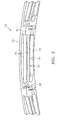
FIG. 3 is an illustration of a hydrostatic non-contact seal with an axially offset outer ring. -
FIG. 4 is a side cutaway illustration of a gas turbine engine. - It is noted that various connections are set forth between elements in the following description and in the drawings (the contents of which are incorporated in this specification by way of reference). It is noted that these connections are general and, unless specified otherwise, may be direct or indirect and that this specification is not intended to be limiting in this respect. A coupling between two or more entities may refer to a direct connection or an indirect connection. An indirect connection may incorporate one or more intervening entities or a space/gap between the entities that are being coupled to one another.
- Aspects of the disclosure may be applied in connection with a gas turbine engine.
-
FIG. 1 illustrates anassembly 20 for rotational equipment with anaxial centerline 22. An example of such rotational equipment is a gas turbine engine for an aircraft propulsion system, an exemplary embodiment of which is described below in further detail. However, theassembly 20 of the present disclosure is not limited to such an aircraft or gas turbine engine application. Theassembly 20, for example, may alternatively be configured with rotational equipment such as an industrial gas turbine engine, a wind turbine, a water turbine, or any other apparatus in which a seal is provided between a stator structure and a rotor structure. - The
assembly 20 ofFIG. 1 includes astator structure 24, arotor structure 26 and aseal assembly 28. Thisseal assembly 28 is mounted with thestator structure 24, and configured to substantially seal anannular gap 30 between thestator structure 24 and therotor structure 26 as described below in further detail. - The
stator structure 24 includes aseal carrier 32. Thisseal carrier 32 may be a discrete, unitary annular body. Alternatively, theseal carrier 32 may be configured with another component / portion of thestator structure 24. Theseal carrier 32 has an inner radialseal carrier surface 34. Thisseal carrier surface 34 may be substantially cylindrical, and extends circumferentially around and faces towards theaxial centerline 22. Theseal carrier surface 34 at least partially forms a bore in thestator structure 24. This bore is sized to receive theseal assembly 28, which may be fixedly attached to theseal carrier 32 by, for example, a press fit connection between theseal assembly 28 and theseal carrier surface 34. - The
rotor structure 26 includes aseal land 36. Thisseal land 36 may be a discrete, unitary annular body. Alternatively, theseal land 36 may be configured with another component / portion of therotor structure 26. Theseal land 36 has an outer radialseal land surface 38. Thisseal land surface 38 may be substantially cylindrical, and extends circumferentially around and faces away from theaxial centerline 22. Theseal land surface 38 is disposed to face towards and is axially aligned with theseal carrier surface 34. WhileFIG. 1 illustrates thesurfaces axial centerline 22, theseal land surface 38 may alternatively be longer or shorter than theseal carrier surface 34 in other embodiments. - The
seal assembly 28 includes aprimary seal device 40 and one or moresecondary seal devices 42; e.g., 1, 2, 3 or moresecondary seal devices 42. Theseal assembly 28 also includes one or more additional components for positioning, supporting and/or mounting one or more of theseal devices stator structure 24. Theseal assembly 28 ofFIG. 1 , for example, includes afirst ring structure 44 configured for positioning, supporting and/or mounting thesecondary seal devices 42 relative to theprimary seal device 40. Thisfirst ring structure 44 may also be configured for axially positioning and/or supporting asecond end surface 46 of theprimary seal device 40 relative to thestator structure 24. Theseal assembly 28 ofFIG. 1 also includes a second ring structure 48 (e.g., a scalloped support ring) configured for axially positioning and/or supporting afirst end surface 50 of theprimary seal device 40 relative to thestator structure 24. However, thesecond ring structure 48 may be omitted where, for example, thefirst end surface 50 of theprimary seal device 40 may be abutted against another component / portion of the stator structure 24 (e.g., an annular or castellated shoulder) or otherwise axially positioned / secure with thestator structure 24. - The
primary seal device 40 may be configured as an annular non-contact seal device and, more particularly, a hydrostatic non-contact seal device. An example of such a hydrostatic non-contact seal device is a Hydrostatic Adaptive Low Leakage ("HALO™)" seal; however, theprimary seal device 40 of the present disclosure is not limited to the foregoing exemplary hydrostatic non-contact seal device. - The
primary seal device 40 includes a plurality ofseal shoes 54, a plurality ofspring elements 56 and a seal base/outer ring 52 that is axially (referring to axial centerline 22) offset from thespring elements 56. The seal shoes 54 are configured as arcuate bodies arranged circumferentially about theaxial centerline 22 in an annular array. This annular array of the seal shoes 54 extends circumferentially around theaxial centerline 22, thereby forming an inner bore at an innerradial side 62 of theprimary seal device 40. The inner bore is sized to receive theseal land 36, where therotor structure 26 projects axially through (or into) the inner bore formed by the seal shoes 54. - Referring to
FIGs. 1-3 , each of the seal shoes 54 extends radially from the innerradial side 62 of theprimary seal device 40 to an outerradial surface 64 of thatseal shoe 54. Each of the seal shoes 54 extends circumferentially around theaxial centerline 22 between opposing first and secondcircumferential sides seal shoe 54. - Referring to
FIG. 1 , each of the seal shoes 54 extends axially along theaxial centerline 22 between afirst shoe end 70 and asecond shoe end 72. Thefirst shoe end 70 may be axially offset from and project axially away from thefirst end surface 50. Thesecond shoe end 72 may be axially offset from and project axially away from thesecond end surface 46. The seal shoes 54 of the present disclosure, however, are not limited to such exemplary relationships. - Each of the seal shoes 54 may include an arcuate end surface 74 generally at (e.g., on, adjacent or proximate) the
second shoe end 72. In the array (seeFIG. 2 ), these arcuate end surfaces 74 collectively form a generally annular (but circumferentially segmented) end surface 76 configured for sealingly engaging with thesecondary seal devices 42; seeFIG. 1 . The seal shoes 54 of the present disclosure, however, are not limited to the foregoing exemplary configuration. - Each of the seal shoes 54 includes one or more arcuate protrusions 78, which collectively form one or more (e.g., a plurality) of axially spaced generally annular (e.g., circumferentially segmented) ribs 80 at the inner
radial side 62. Distal inner radial ends 82 of one or more of these ribs 80 are configured to be arranged in close proximity with (but not touch) and thereby sealingly engage theseal land surface 38 in a non-contact manner (seeFIG. 1 ), where therotor structure 26 project axially through (or into) the inner bore formed by the seal shoes 54. The ribs 80 therefore are configured, generally speaking, as non-contact knife edge seal elements. - Referring to
FIGs. 1-3 , thespring elements 56 are arranged circumferentially about theaxial centerline 22 in an annular array. Thespring elements 56 are also arranged radially between the seal shoes 54 and theseal base 52. Thespring element 56, for example, includes one ormore mounts 83 and 84 (e.g., generally radial fingers / projections) and one or more beams 86 (e.g., cantilever-leaf springs). Thefirst mount 83 is connected to a respective one of the seal shoes 54 at (e.g., on, adjacent or proximate) the firstcircumferential side 68, where the opposing secondcircumferential side 66 of thatseal shoe 54 is free floating. Thesecond mount 84 is connected to an offset seal base/outer ring 52, and is generally circumferentially aligned with or near the secondcircumferential side 68. With respect to theaxial center line 22, the offsetseal base 52 is axially offset with respect to the radially mostdistal beam 86, such that the offsetseal base 52 does not radially cover the radially mostdistal beam 86. Thebeams 86 are radially stacked and spaced apart with one another. Each of thesebeams 86 extends laterally (e.g., tangentially or circumferentially) from thefirst mount 83 to thesecond mount 84. Thesespring elements 56 may thereby laterally overlap a major circumferential portion (e.g., ∼50-100%) of theseal shoe 54. In contrast, the offsetseal base 52 does not laterally overlap at least a primary circumferential portion (e.g., ∼65-100%) of the radially mostdistal beam 86. Subsequently, the radial height ofseal assembly 28 may be substantially reduced, to increase radial space and improve packaging with adjacent hardware.FIGs. 1-3 illustrate an embodiment in which the offset seal base/outer ring 52 does not overlap any portion of the radially most distal of thebeams 86. Thespring elements 56 of the present disclosure, however, are not limited to the foregoing exemplary configuration or values. - During operation of the
primary seal device 40, rotation of therotor structure 26 may develop aerodynamic forces and apply a fluid pressure to the seal shoes 54 causing eachseal shoe 54 to respectively move radially relative to theseal land surface 38. The fluid velocity may increase as a gap between theseal shoe 54 and sealland surface 38 increases, thus reducing pressure in the gap and drawing theseal shoe 54 radially inwardly toward theseal land surface 38. As the gap closes, the velocity may decrease and the pressure may increase within the gap, thus, forcing theseal shoe 54 radially outward from theseal land surface 38. Therespective spring element 56 may deflect and move with theseal shoe 54 to create a primary seal of the gap between theseal land surface 38 and ribs 80 within predetermined design tolerances. - Referring again to
FIG. 1 , while theprimary seal device 40 is operable to generally seal theannular gap 30 between thestator structure 24 and therotor structure 26 as described above, fluid (e.g., gas) may still flow axially throughpassages 96 defined by radial gaps between thecomponents secondary seal devices 42 therefore are provided to seal off thesepassages 96 and, thereby, further and more completely seal theannular gap 30. - Each of the
secondary seal devices 42 may be configured as a ring seal element such as, but not limited to, a split ring. Alternatively, one or more of thesecondary seal devices 42 may be configured as a full hoop body ring, an annular brush seal or any other suitable ring-type seal. - As described above, the
assembly 20 of the present disclosure may be configured with various different types and configurations of rotational equipment.FIG. 4 illustrates one such type and configuration of the rotational equipment - a geared turbofangas turbine engine 106. Such aturbine engine 106 includes various stator structures (e.g., bearing supports, hubs, cases, etc.) as well as various rotor structures (e.g., rotor disks, shafts, etc.) as described below, where thestator structure 24 and therotor structure 26 can respectively be configured as anyone of the foregoing structures in theturbine engine 106 ofFIG. 4 , or other structures not mentioned herein. Referring again toFIG. 1 , while theprimary seal device 40 is operable to generally seal theannular gap 30 between thestator structure 24 and therotor structure 26 as described above, fluid (e.g., gas) may still flow axially throughpassages 96 defined by radial gaps between thecomponents secondary seal devices 42 therefore are provided to seal off thesepassages 96 and, thereby, further and more completely seal theannular gap 30. - The
secondary seal devices 42 ofFIG. 1 are arranged together in an axial stack. In this stack, each of thesecondary seal devices 42 axially engages (e.g., contacts) another adjacent one of thesecondary seal devices 42. The stack of thesecondary seal devices 42 is arranged with thefirst ring structure 44, which positions and mounts thesecondary seal devices 42 with thestator structure 24 adjacent theprimary seal device 40. In this arrangement, the stack of thesecondary seal devices 42 is operable to axially engage and form a seal between the end surface 76 of the array of the seal shoes 54 and anannular surface 98 of thefirst ring structure 44. Thesesurfaces 76 and 98 are axially aligned with one another, which enables the stack of thesecondary seal devices 42 to slide radially against, but maintain sealing engagement with, the end surface 76 as the seal shoes 54 move radially relative to theseal land surface 38 as described above. - The
first ring structure 44 may include a secondary sealdevice support ring 100 and aretention ring 102. Thesupport ring 100 is configured with an annular full hoop body, which extends circumferentially around theaxially centerline 22. Thesupport ring 100 includes theannular surface 98, and is disposed axially adjacent and engaged with theseal base 52. - The
retention ring 102 is configured with an annular full hoop body, which extends circumferentially around theaxially centerline 22. Theretention ring 102 is disposed axially adjacent and engaged with thesupport ring 100, thereby capturing the stack of thesecondary seal devices 42 within an annular channel formed between therings secondary seal devices 42 may also or alternatively be attached to one of therings - Referring still to
FIG. 4 , theturbine engine 106 extends along an axial centerline 108 (e.g., the centerline 22) between anupstream airflow inlet 110 and adownstream airflow exhaust 112. Theturbine engine 106 includes afan section 114, acompressor section 115, acombustor section 116 and aturbine section 117. Thecompressor section 115 includes a low pressure compressor (LPC)section 115A and a high pressure compressor (HPC)section 115B. Theturbine section 117 includes a high pressure turbine (HPT)section 117A and a low pressure turbine (LPT)section 117B. - The engine sections 114-117 are arranged sequentially along the
centerline 108 within anengine housing 118, a portion or component of which may include or be connected to thestator structure 24. Thishousing 118 includes an inner case 120 (e.g., a core case) and an outer case 122 (e.g., a fan case). Theinner case 120 may house one or more of the engine sections; e.g., an engine core. Theouter case 122 may house at least thefan section 114. - Each of the
engine sections - The
fan rotor 124 is connected to agear train 130, for example, through afan shaft 132. Thegear train 130 and theLPC rotor 125 are connected to and driven by theLPT rotor 128 through alow speed shaft 133. TheHPC rotor 126 is connected to and driven by theHPT rotor 127 through ahigh speed shaft 134. The shafts 132-134 are rotatably supported by a plurality ofbearings 136; e.g., rolling element and/or thrust bearings. Each of thesebearings 136 is connected to theengine housing 118 by at least one stationary structure such as, for example, an annular support strut. - During operation, air enters the
turbine engine 106 through theairflow inlet 110. This air is directed through thefan section 114 and into acore gas path 138 and abypass gas path 140. Thecore gas path 138 flows sequentially through the engine sections 115-117. Thebypass gas path 140 flows away from thefan section 114 through a bypass duct, which circumscribes and bypasses the engine core. The air within thecore gas path 138 may be referred to as "core air". The air within thebypass gas path 140 may be referred to as "bypass air". - The core air is compressed by the
compressor rotors combustion chamber 142 of a combustor in thecombustor section 116. Fuel is injected into thecombustion chamber 142 and mixed with the compressed core air to provide a fuel-air mixture. This fuel air mixture is ignited and combustion products thereof flow through and sequentially cause theturbine rotors turbine rotors compressor rotors turbine rotor 128 also drives rotation of thefan rotor 124, which propels bypass air through and out of thebypass gas path 140. The propulsion of the bypass air may account for a majority of thrust generated by theturbine engine 106, e.g., more than seventy-five percent (75%) of engine thrust. Theturbine engine 106 of the present disclosure, however, is not limited to the foregoing exemplary thrust ratio. - The
assembly 20 may be included in various aircraft and industrial turbine engines other than the one described above as well as in other types of rotational equipment; e.g., wind turbines, water turbines, rotary engines, etc. Theassembly 20, for example, may be included in a geared turbine engine where a gear train connects one or more shafts to one or more rotors in a fan section, a compressor section and/or any other engine section. Alternatively, theassembly 20 may be included in a turbine engine configured without a gear train. Theassembly 20 may be included in a geared or non-geared turbine engine configured with a single spool, with two spools (e.g., see FIG. 5), or with more than two spools. The turbine engine may be configured as a turbofan engine, a turbojet engine, a propfan engine, a pusher fan engine or any other type of turbine engine. The present invention therefore is not limited to any particular types or configurations of turbine engines or rotational equipment. - While various embodiments of the present invention have been disclosed, it will be apparent to those of ordinary skill in the art that many more embodiments and implementations are possible within the scope of the invention. For example, the embodiments of the present invention as described herein include several aspects and embodiments that include particular features. Although these features may be described individually, it is within the scope of the embodiments of the present invention that some or all of these features may be combined with any one of the aspects and remain within the scope of the invention. Accordingly, the present invention is not to be restricted except in light of the attached claims and their equivalents.
Claims (13)
- A non-contact seal assembly (28), comprising:a plurality of seal shoes (54) arranged about a centerline (22) in an annular array, the seal shoes (54) including a first seal shoe (54) extending axially along the centerline (22) between a first shoe end (70) and a second shoe end (72);a seal base (52) circumscribing axially offset from the annular array of the seal shoes (54); anda plurality of spring elements (56), each of the spring elements (56) radially distal from and connecting to a respective one of the seal shoes (54), and each of the plurality of spring elements (56) is axially adjacent to the seal base (52).
- A non-contact seal assembly (28), comprising:a plurality of seal shoes (54) arranged about a centerline (22) in an annular array, the seal shoes (54) including a first seal shoe (54) extending axially along the centerline (22) between a first shoe end (70) and a second shoe end (72);a seal base (52) circumscribing axially offset along the centerline (22) from the annular array of the seal shoes (54); anda plurality of spring elements (56), each of the spring elements (56) radially between and connecting a respective one of the seal shoes (54) with the seal base (52),where a void is formed by a most radially distal one of the plurality of spring elements (56), the axially offset seal base (52), a stator structure (24), and a ring structure (48) that is axially separated from the axially offset seal base (52) by the plurality of spring elements (56).
- The non-contact seal assembly (28) of claim 1 or 2, where the seal base (52) is connected to a seal carrier surface (34) that is substantially cylindrical and extends circumferentially around and faces towards the centerline (22).
- The non-contact seal assembly (28) of claim 1, 2 or 3, further comprising a first ring structure (44) configured and arranged to at least one of position, support or mount to a secondary seal device (42) axially separated from the seal base (52) and radially adjacent to the first seal shoe (54).
- The non-contact seal assembly (28) of claim 1, 2 or 3, further comprising a secondary seal device (42) axially and radially adjacent to the seal base (52) and axially adjacent to the first seal shoe (54).
- The non-contact seal assembly (28) of any preceding claim, where the seal assembly (28) comprises nickel alloy.
- The non-contact assembly (28) of any of claims 1 to 5, where the seal assembly (28) comprises one of cobalt alloy or aluminum.
- The non-contact seal assembly (28) of any preceding claim, where the first seal shoe (54) extends circumferentially, at the first shoe end (70), between a first shoe side (66) and a second shoe side (68) for a seal shoe length.
- The non-contact seal assembly (28) of any preceding claim, where the seal shoes (54) collectively form a substantially annular end surface (76) at the second shoe end (72).
- An assembly (20) for rotational equipment with an axial centerline (22), the assembly (20) comprising:a stator structure (24);a rotor structure (26); andthe seal assembly (28) of claim 1 configured to substantially seal an annular gap (30) between the stator structure (24) and the rotor structure (26), the seal assembly (20) comprising a hydrostatic non-contact seal device (40) including the plurality of seal shoes (54), the axially offset seal base (52) and the plurality of spring elements (56), the seal shoes (54) sealingly engaging the rotor structure (26), the axially offset seal base (52) mounted with the stator structure (24), and where the axially offset seal base (52) is axially offset with respect to the plurality of spring elements (56).
- The assembly (20) for rotational equipment of claim 10, where the axially offset seal base (52) is connected to a seal carrier surface (34) that is substantially cylindrical and extends circumferentially around and faces towards the centerline (22).
- The assembly (20) for rotational equipment of claim 10 or 11, further comprising a first ring structure (44) configured and arranged to at least one of position, support or mount to a secondary seal device (42) axially separated from the axially offset seal base (52) and radially adjacent to the first seal shoe (54).
- The assembly (20) for rotational equipment of claim 10, further comprising a secondary seal device (42) that is axially and radially adjacent to the axially offset seal base (52) and axially adjacent to the first seal shoe (54).
Applications Claiming Priority (1)
| Application Number | Priority Date | Filing Date | Title |
|---|---|---|---|
| US15/650,457 US10731761B2 (en) | 2017-07-14 | 2017-07-14 | Hydrostatic non-contact seal with offset outer ring |
Publications (1)
| Publication Number | Publication Date |
|---|---|
| EP3428490A1 true EP3428490A1 (en) | 2019-01-16 |
Family
ID=62165500
Family Applications (1)
| Application Number | Title | Priority Date | Filing Date |
|---|---|---|---|
| EP18172186.1A Pending EP3428490A1 (en) | 2017-07-14 | 2018-05-14 | Hydrostatic non-contact seal with offset outer ring |
Country Status (2)
| Country | Link |
|---|---|
| US (1) | US10731761B2 (en) |
| EP (1) | EP3428490A1 (en) |
Cited By (1)
| Publication number | Priority date | Publication date | Assignee | Title |
|---|---|---|---|---|
| EP3783250A1 (en) * | 2019-08-21 | 2021-02-24 | Raytheon Technologies Corporation | Non-contact seal asembly with chamfered seal shoe |
Families Citing this family (3)
| Publication number | Priority date | Publication date | Assignee | Title |
|---|---|---|---|---|
| US10746039B2 (en) * | 2017-09-25 | 2020-08-18 | United Technologies Corporation | Hydrostatic seal pinned cartridge |
| US10822983B2 (en) * | 2018-02-06 | 2020-11-03 | Raytheon Technologies Corportation | Hydrostatic seal with abradable teeth for gas turbine engine |
| US20220268166A1 (en) * | 2021-02-19 | 2022-08-25 | Raytheon Technologies Corporation | Non-contacting seal assembly with internal coating |
Citations (4)
| Publication number | Priority date | Publication date | Assignee | Title |
|---|---|---|---|---|
| EP3009611A1 (en) * | 2014-10-17 | 2016-04-20 | United Technologies Corporation | Circumferential seal with seal dampening elements |
| EP3029361A1 (en) * | 2014-10-21 | 2016-06-08 | United Technologies Corporation | Seal ring |
| EP3034801A1 (en) * | 2014-10-23 | 2016-06-22 | United Technologies Corporation | Seal support structure |
| EP3133241A1 (en) * | 2015-08-19 | 2017-02-22 | United Technologies Corporation | Non-contact seal assembly for rotational equipment |
Family Cites Families (45)
| Publication number | Priority date | Publication date | Assignee | Title |
|---|---|---|---|---|
| GB2092242B (en) | 1981-01-31 | 1984-12-19 | Rolls Royce | Non-contacting gas seal |
| GB2092243B (en) | 1981-01-31 | 1984-12-05 | Rolls Royce | Non-contacting gas seal |
| DE3828833A1 (en) * | 1988-08-25 | 1990-03-01 | Mtu Muenchen Gmbh | DEVICE FOR SEALING MEDIA, LIQUIDS AND / OR GASES, DIFFERENT PRESSURES, ROOMS IN PARTICULAR, IN PARTICULAR FOR TURBO MACHINES |
| US5333993A (en) | 1993-03-01 | 1994-08-02 | General Electric Company | Stator seal assembly providing improved clearance control |
| US6226975B1 (en) | 1999-09-14 | 2001-05-08 | Steven G. Ingistov | Turbine power plant having a floating brush seal |
| GB0226685D0 (en) | 2002-11-15 | 2002-12-24 | Rolls Royce Plc | Sealing arrangement |
| US7410173B2 (en) | 2003-05-01 | 2008-08-12 | Justak John F | Hydrodynamic brush seal |
| US8002285B2 (en) | 2003-05-01 | 2011-08-23 | Justak John F | Non-contact seal for a gas turbine engine |
| US8919781B2 (en) | 2003-05-01 | 2014-12-30 | Advanced Technologies Group, Inc. | Self-adjusting non-contact seal |
| US20040217549A1 (en) | 2003-05-01 | 2004-11-04 | Justak John F. | Hydrodynamic brush seal |
| US8172232B2 (en) * | 2003-05-01 | 2012-05-08 | Advanced Technologies Group, Inc. | Non-contact seal for a gas turbine engine |
| US7216871B1 (en) | 2004-05-04 | 2007-05-15 | Advanced Components & Materials, Inc. | Non-contacting seal for rotating surfaces |
| US9145785B2 (en) | 2011-03-04 | 2015-09-29 | General Electric Company | Aerodynamic seal assemblies for turbo-machinery |
| US20130195627A1 (en) | 2012-01-27 | 2013-08-01 | Jorn A. Glahn | Thrust balance system for gas turbine engine |
| US9097350B2 (en) | 2012-04-02 | 2015-08-04 | United Technologies Corporation | Axial non-contact seal |
| US9255642B2 (en) * | 2012-07-06 | 2016-02-09 | General Electric Company | Aerodynamic seals for rotary machine |
| US9587746B2 (en) * | 2012-07-31 | 2017-03-07 | General Electric Company | Film riding seals for rotary machines |
| US9140133B2 (en) | 2012-08-14 | 2015-09-22 | United Technologies Corporation | Threaded full ring inner air-seal |
| US9045994B2 (en) | 2012-10-31 | 2015-06-02 | General Electric Company | Film riding aerodynamic seals for rotary machines |
| US10119474B2 (en) * | 2013-03-15 | 2018-11-06 | United Technologies Corporation | Vibration damping apparatus for hydrostatic seal of gas turbine engine |
| US9359908B2 (en) * | 2014-07-08 | 2016-06-07 | General Electric Company | Film riding seal assembly for turbomachinery |
| US9963991B2 (en) * | 2014-10-01 | 2018-05-08 | United Technologies Corporation | Brush seal plate |
| US10801348B2 (en) | 2014-10-14 | 2020-10-13 | Raytheon Technologies Corporation | Non-contacting dynamic seal |
| US10443450B2 (en) | 2014-10-24 | 2019-10-15 | United Technologies Corporation | Seal support structure for a circumferential seal of a gas turbine engine |
| US10161259B2 (en) * | 2014-10-28 | 2018-12-25 | General Electric Company | Flexible film-riding seal |
| US10370991B2 (en) * | 2014-11-07 | 2019-08-06 | United Technologies Corporation | Gas turbine engine and seal assembly therefore |
| US10190431B2 (en) * | 2015-02-11 | 2019-01-29 | General Electric Company | Seal assembly for rotary machine |
| US10094232B2 (en) | 2015-08-13 | 2018-10-09 | United Technologies Corporation | Self crystalline orientation for increased compliance |
| US10060280B2 (en) | 2015-10-15 | 2018-08-28 | United Technologies Corporation | Turbine cavity sealing assembly |
| US20170130732A1 (en) | 2015-11-06 | 2017-05-11 | United Technologies Corporation | Compressor exit seal |
| US10030531B2 (en) | 2016-01-22 | 2018-07-24 | United Technologies Corporation | Seal shoe for a hydrostatic non-contact seal device |
| US10221714B2 (en) | 2016-01-22 | 2019-03-05 | United Technologies Corporation | Secondary seal device(s) with alignment tab(s) |
| US10428672B2 (en) | 2016-02-08 | 2019-10-01 | United Technologies Corporation | Floating, non-contact seal and dimensions thereof |
| US20170306780A1 (en) | 2016-04-25 | 2017-10-26 | United Technologies Corporation | Floating, non-contact seal with rounded edge |
| US9850770B2 (en) | 2016-04-29 | 2017-12-26 | Stein Seal Company | Intershaft seal with asymmetric sealing ring |
| US10961860B2 (en) | 2016-08-15 | 2021-03-30 | Raytheon Technologies Corporation | Non-contact seal with removal features |
| US10100657B2 (en) | 2016-08-15 | 2018-10-16 | United Technologies Corporation | Non-contact seal with monolithic/unitary carrier structure |
| US10370996B2 (en) | 2016-08-23 | 2019-08-06 | United Technologies Corporation | Floating, non-contact seal with offset build clearance for load imbalance |
| US10385715B2 (en) | 2016-08-29 | 2019-08-20 | United Technologies Corporation | Floating, non-contact seal with angled beams |
| US10550708B2 (en) | 2016-08-31 | 2020-02-04 | United Technologies Corporation | Floating, non-contact seal with at least three beams |
| US9995163B2 (en) | 2016-09-02 | 2018-06-12 | United Technologies Corporation | Halo seal attached secondary seal cover arrangement |
| US10082039B2 (en) | 2016-11-02 | 2018-09-25 | United Technologies Corporation | Segmented annular seal |
| US10718270B2 (en) | 2017-06-15 | 2020-07-21 | Raytheon Technologies Corporation | Hydrostatic non-contact seal with dual material |
| US10641180B2 (en) | 2017-06-15 | 2020-05-05 | United Technologies Corporation | Hydrostatic non-contact seal with varied thickness beams |
| US10337621B2 (en) | 2017-06-23 | 2019-07-02 | United Technologies Corporation | Hydrostatic non-contact seal with weight reduction pocket |
-
2017
- 2017-07-14 US US15/650,457 patent/US10731761B2/en active Active
-
2018
- 2018-05-14 EP EP18172186.1A patent/EP3428490A1/en active Pending
Patent Citations (4)
| Publication number | Priority date | Publication date | Assignee | Title |
|---|---|---|---|---|
| EP3009611A1 (en) * | 2014-10-17 | 2016-04-20 | United Technologies Corporation | Circumferential seal with seal dampening elements |
| EP3029361A1 (en) * | 2014-10-21 | 2016-06-08 | United Technologies Corporation | Seal ring |
| EP3034801A1 (en) * | 2014-10-23 | 2016-06-22 | United Technologies Corporation | Seal support structure |
| EP3133241A1 (en) * | 2015-08-19 | 2017-02-22 | United Technologies Corporation | Non-contact seal assembly for rotational equipment |
Cited By (1)
| Publication number | Priority date | Publication date | Assignee | Title |
|---|---|---|---|---|
| EP3783250A1 (en) * | 2019-08-21 | 2021-02-24 | Raytheon Technologies Corporation | Non-contact seal asembly with chamfered seal shoe |
Also Published As
| Publication number | Publication date |
|---|---|
| US10731761B2 (en) | 2020-08-04 |
| US20190017606A1 (en) | 2019-01-17 |
Similar Documents
| Publication | Publication Date | Title |
|---|---|---|
| US10208615B2 (en) | Seal shoe for a hydrostatic non-contact seal device | |
| EP3431838B1 (en) | Non-contact seal with resilient biasing element(s) | |
| US10563532B2 (en) | Non-contact seal with monolithic/unitary carrier structure | |
| US10612669B2 (en) | Shaped spring element for a non-contact seal device | |
| EP3431836B1 (en) | Non-contact seal with non-straight spring beam(s) | |
| EP3418610B1 (en) | Hydrostatic non-contact seal with weight reduction pocket | |
| EP3428489B1 (en) | Hydrostatic non-contact seal with seal carrier elimination | |
| US10697550B2 (en) | Non-contact seal with progressive radial stop(s) | |
| EP3415798B1 (en) | Hydrostatic non-contact seal with varied thickness beams | |
| US20170211402A1 (en) | Secondary seal device(s) with alignment tab(s) | |
| US10718270B2 (en) | Hydrostatic non-contact seal with dual material | |
| EP3783250A1 (en) | Non-contact seal asembly with chamfered seal shoe | |
| EP3428490A1 (en) | Hydrostatic non-contact seal with offset outer ring |
Legal Events
| Date | Code | Title | Description |
|---|---|---|---|
| PUAI | Public reference made under article 153(3) epc to a published international application that has entered the european phase |
Free format text: ORIGINAL CODE: 0009012 |
|
| STAA | Information on the status of an ep patent application or granted ep patent |
Free format text: STATUS: THE APPLICATION HAS BEEN PUBLISHED |
|
| AK | Designated contracting states |
Kind code of ref document: A1 Designated state(s): AL AT BE BG CH CY CZ DE DK EE ES FI FR GB GR HR HU IE IS IT LI LT LU LV MC MK MT NL NO PL PT RO RS SE SI SK SM TR |
|
| AX | Request for extension of the european patent |
Extension state: BA ME |
|
| STAA | Information on the status of an ep patent application or granted ep patent |
Free format text: STATUS: REQUEST FOR EXAMINATION WAS MADE |
|
| 17P | Request for examination filed |
Effective date: 20190716 |
|
| RBV | Designated contracting states (corrected) |
Designated state(s): AL AT BE BG CH CY CZ DE DK EE ES FI FR GB GR HR HU IE IS IT LI LT LU LV MC MK MT NL NO PL PT RO RS SE SI SK SM TR |
|
| STAA | Information on the status of an ep patent application or granted ep patent |
Free format text: STATUS: EXAMINATION IS IN PROGRESS |
|
| 17Q | First examination report despatched |
Effective date: 20191206 |
|
| STAA | Information on the status of an ep patent application or granted ep patent |
Free format text: STATUS: EXAMINATION IS IN PROGRESS |
|
| RAP1 | Party data changed (applicant data changed or rights of an application transferred) |
Owner name: RAYTHEON TECHNOLOGIES CORPORATION |
|
| RAP3 | Party data changed (applicant data changed or rights of an application transferred) |
Owner name: RTX CORPORATION |