US10697550B2 - Non-contact seal with progressive radial stop(s) - Google Patents
Non-contact seal with progressive radial stop(s) Download PDFInfo
- Publication number
- US10697550B2 US10697550B2 US16/541,898 US201916541898A US10697550B2 US 10697550 B2 US10697550 B2 US 10697550B2 US 201916541898 A US201916541898 A US 201916541898A US 10697550 B2 US10697550 B2 US 10697550B2
- Authority
- US
- United States
- Prior art keywords
- seal
- assembly
- mount
- shoes
- shoe
- Prior art date
- Legal status (The legal status is an assumption and is not a legal conclusion. Google has not performed a legal analysis and makes no representation as to the accuracy of the status listed.)
- Active
Links
Images


Classifications
-
- F—MECHANICAL ENGINEERING; LIGHTING; HEATING; WEAPONS; BLASTING
- F16—ENGINEERING ELEMENTS AND UNITS; GENERAL MEASURES FOR PRODUCING AND MAINTAINING EFFECTIVE FUNCTIONING OF MACHINES OR INSTALLATIONS; THERMAL INSULATION IN GENERAL
- F16J—PISTONS; CYLINDERS; SEALINGS
- F16J15/00—Sealings
- F16J15/44—Free-space packings
- F16J15/441—Free-space packings with floating ring
- F16J15/442—Free-space packings with floating ring segmented
-
- F—MECHANICAL ENGINEERING; LIGHTING; HEATING; WEAPONS; BLASTING
- F16—ENGINEERING ELEMENTS AND UNITS; GENERAL MEASURES FOR PRODUCING AND MAINTAINING EFFECTIVE FUNCTIONING OF MACHINES OR INSTALLATIONS; THERMAL INSULATION IN GENERAL
- F16J—PISTONS; CYLINDERS; SEALINGS
- F16J15/00—Sealings
- F16J15/44—Free-space packings
- F16J15/441—Free-space packings with floating ring
-
- F—MECHANICAL ENGINEERING; LIGHTING; HEATING; WEAPONS; BLASTING
- F01—MACHINES OR ENGINES IN GENERAL; ENGINE PLANTS IN GENERAL; STEAM ENGINES
- F01D—NON-POSITIVE DISPLACEMENT MACHINES OR ENGINES, e.g. STEAM TURBINES
- F01D11/00—Preventing or minimising internal leakage of working-fluid, e.g. between stages
- F01D11/02—Preventing or minimising internal leakage of working-fluid, e.g. between stages by non-contact sealings, e.g. of labyrinth type
- F01D11/025—Seal clearance control; Floating assembly; Adaptation means to differential thermal dilatations
-
- F—MECHANICAL ENGINEERING; LIGHTING; HEATING; WEAPONS; BLASTING
- F01—MACHINES OR ENGINES IN GENERAL; ENGINE PLANTS IN GENERAL; STEAM ENGINES
- F01D—NON-POSITIVE DISPLACEMENT MACHINES OR ENGINES, e.g. STEAM TURBINES
- F01D11/00—Preventing or minimising internal leakage of working-fluid, e.g. between stages
- F01D11/08—Preventing or minimising internal leakage of working-fluid, e.g. between stages for sealing space between rotor blade tips and stator
- F01D11/14—Adjusting or regulating tip-clearance, i.e. distance between rotor-blade tips and stator casing
- F01D11/16—Adjusting or regulating tip-clearance, i.e. distance between rotor-blade tips and stator casing by self-adjusting means
-
- F—MECHANICAL ENGINEERING; LIGHTING; HEATING; WEAPONS; BLASTING
- F01—MACHINES OR ENGINES IN GENERAL; ENGINE PLANTS IN GENERAL; STEAM ENGINES
- F01D—NON-POSITIVE DISPLACEMENT MACHINES OR ENGINES, e.g. STEAM TURBINES
- F01D5/00—Blades; Blade-carrying members; Heating, heat-insulating, cooling or antivibration means on the blades or the members
- F01D5/02—Blade-carrying members, e.g. rotors
- F01D5/03—Annular blade-carrying members having blades on the inner periphery of the annulus and extending inwardly radially, i.e. inverted rotors
-
- F—MECHANICAL ENGINEERING; LIGHTING; HEATING; WEAPONS; BLASTING
- F02—COMBUSTION ENGINES; HOT-GAS OR COMBUSTION-PRODUCT ENGINE PLANTS
- F02C—GAS-TURBINE PLANTS; AIR INTAKES FOR JET-PROPULSION PLANTS; CONTROLLING FUEL SUPPLY IN AIR-BREATHING JET-PROPULSION PLANTS
- F02C3/00—Gas-turbine plants characterised by the use of combustion products as the working fluid
- F02C3/14—Gas-turbine plants characterised by the use of combustion products as the working fluid characterised by the arrangement of the combustion chamber in the plant
-
- F—MECHANICAL ENGINEERING; LIGHTING; HEATING; WEAPONS; BLASTING
- F16—ENGINEERING ELEMENTS AND UNITS; GENERAL MEASURES FOR PRODUCING AND MAINTAINING EFFECTIVE FUNCTIONING OF MACHINES OR INSTALLATIONS; THERMAL INSULATION IN GENERAL
- F16J—PISTONS; CYLINDERS; SEALINGS
- F16J15/00—Sealings
- F16J15/44—Free-space packings
- F16J15/445—Free-space packings with means for adjusting the clearance
-
- F—MECHANICAL ENGINEERING; LIGHTING; HEATING; WEAPONS; BLASTING
- F02—COMBUSTION ENGINES; HOT-GAS OR COMBUSTION-PRODUCT ENGINE PLANTS
- F02C—GAS-TURBINE PLANTS; AIR INTAKES FOR JET-PROPULSION PLANTS; CONTROLLING FUEL SUPPLY IN AIR-BREATHING JET-PROPULSION PLANTS
- F02C7/00—Features, components parts, details or accessories, not provided for in, or of interest apart form groups F02C1/00 - F02C6/00; Air intakes for jet-propulsion plants
- F02C7/28—Arrangement of seals
-
- F—MECHANICAL ENGINEERING; LIGHTING; HEATING; WEAPONS; BLASTING
- F05—INDEXING SCHEMES RELATING TO ENGINES OR PUMPS IN VARIOUS SUBCLASSES OF CLASSES F01-F04
- F05D—INDEXING SCHEME FOR ASPECTS RELATING TO NON-POSITIVE-DISPLACEMENT MACHINES OR ENGINES, GAS-TURBINES OR JET-PROPULSION PLANTS
- F05D2220/00—Application
- F05D2220/30—Application in turbines
- F05D2220/32—Application in turbines in gas turbines
- F05D2220/323—Application in turbines in gas turbines for aircraft propulsion, e.g. jet engines
-
- F—MECHANICAL ENGINEERING; LIGHTING; HEATING; WEAPONS; BLASTING
- F05—INDEXING SCHEMES RELATING TO ENGINES OR PUMPS IN VARIOUS SUBCLASSES OF CLASSES F01-F04
- F05D—INDEXING SCHEME FOR ASPECTS RELATING TO NON-POSITIVE-DISPLACEMENT MACHINES OR ENGINES, GAS-TURBINES OR JET-PROPULSION PLANTS
- F05D2240/00—Components
- F05D2240/55—Seals
Definitions
- This disclosure relates generally to rotational equipment and, more particularly, to a non-contact seal assembly for rotational equipment.
- Rotational equipment such as a gas turbine engine typically includes a seal assembly for sealing an annular gap between a rotor and a stationary structure.
- seal assemblies for sealing an annular gap between a rotor and a stationary structure.
- an assembly for rotational equipment.
- This assembly includes a plurality of seal shoes, a seal base, a plurality of spring elements and a frangible element.
- the seal shoes are arranged around an axis in an annular array.
- Each of the spring elements is radially between and connects a respective one of the seal shoes and the seal base.
- a first of the spring elements includes a first mount, a second mount and a spring beam.
- the first mount is connected to a first of the seal shoes.
- the second mount is connected to the seal base.
- the spring beam extends longitudinally between and connects the first mount and the second mount.
- the frangible element is configured to restrict radial outward movement of the first of the seal shoes.
- the non-contact seal assembly includes a plurality of seal shoes arranged around an axis, a seal base circumscribing the seal shoes, and a plurality of spring elements. Each of the spring elements is radially between and connects a respective one of the seal shoes and the seal base.
- a first of the spring elements includes a first mount, a second mount and a spring beam. The first mount is connected to a first of the seal shoes. The second mount is connected to the seal base. The spring beam extends longitudinally between and connects the first mount and the second mount.
- a stop element is radially between the seal base and the first of the seal shoes.
- the stop element is configured to enable a first magnitude of radial outward movement of the first of the seal shoes during a first mode of operation.
- the stop element is also configured to enable a second magnitude of radial outward movement of the first of the seal shoes during a second mode of operation, wherein the second magnitude is greater than the first magnitude.
- the non-contact seal assembly includes a plurality of seal shoes arranged around an axis, a seal base circumscribing the seal shoes, and a plurality of spring elements. Each of the spring elements is radially between and connects a respective one of the seal shoes and the seal base.
- a first of the spring elements includes a first mount, a second mount and a spring beam. The first mount is connected to a first of the seal shoes. The second mount is connected to the seal base. The spring beam extends longitudinally between and connects the first mount and the second mount.
- a stop element is radially between the seal base and the first of the seal shoes. The stop element is configured to have a nominal configuration during a first mode of operation, and an off-nominal configuration, which is different from the nominal configuration, during a second mode of operation.
- the frangible element may be configured to progressively restrict the radial outward movement of the first of the seal shoes.
- the frangible element may be adapted to enable a first magnitude of the radial outward movement of the first of the seal shoes during a first mode of operation.
- the frangible element may be adapted to enable a second magnitude of the radial outward movement of the first of the seal shoes during a second mode of operation.
- the second magnitude may be greater than the first magnitude.
- the frangible element may be configured to have a nominal configuration during a first mode of operation.
- the frangible element may also be configured to have an off-nominal configuration, which is different from the nominal configuration, during a second mode of operation.
- the off-nominal configuration may be a damaged configuration.
- the off-nominal configuration may be a compressed configuration.
- the frangible element may be configured such that is cannot return to the nominal configuration after being in the off-nominal configuration.
- the assembly may also include a non-contact seal assembly, which may include the seal shoes, the seal base, the spring elements and the frangible element.
- the frangible element may be a replaceable component of the non-contact seal assembly.
- the assembly may also include a non-contact seal assembly, which may include the seal shoes, the seal base, the spring elements and the frangible element.
- the frangible element may be brazed to another component of the non-contact seal assembly.
- the frangible element may be configured as or otherwise include a porous body.
- the frangible element may be connected to a first component, where the first component may be configured as or otherwise include the first mount or the second mount.
- the frangible element may be operable to alternately radially engage and radially disengage a second component during nominal operation.
- the second component may be configured as or otherwise include the seal base where the first component is configured as or otherwise includes the first mount.
- the second component may be configured as or otherwise include the first of the seal shoes where the first component is configured as or otherwise includes the second mount.
- the frangible element may be connected to a first component, where the first component may be configured as or otherwise include the seal base or the first of the seal shoes.
- the frangible element may be operable to alternately radially engage and radially disengage a second component during nominal operation.
- the second component may be configured as or otherwise include the first mount where the first component is configured as or otherwise includes the seal base.
- the second component may be configured as or otherwise include the second mount where the first component is configured as or otherwise includes the first of the seal shoes.
- the assembly may include a second frangible element configured to restrict radial outward movement of the first of the seal shoes.
- the second frangible element may be arranged radially between the second mount and the first of the seal shoes.
- the frangible element may be arranged radially between the first mount and the seal base.
- the first of the spring elements may also include a second spring beam extending longitudinally between and connected to the first mount and the second mount.
- the assembly may also include a ring structure axially engaged with the seal base.
- the assembly may also include a secondary seal device mounted with the ring structure.
- the secondary seal device may be configured to substantially seal an annular gap between the ring structure and the annular array of the seal shoes.
- the assembly may include a stationary structure, a rotor structure and a non-contact seal assembly.
- the non-contact seal assembly may include the seal shoes, the seal base and the spring elements.
- the seal assembly may be configured to substantially seal an annular gap between the stationary structure and the rotor structure.
- the seal shoes may circumscribe and sealingly mate with the rotor structure.
- the seal base may be mounted to and radially within the stationary structure.
- FIG. 1 is a partial side sectional illustration of an assembly for rotational equipment.
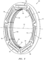
- FIG. 2 is a perspective illustration of a primary seal device of a non-contact seal assembly.
- FIG. 3 is a partial side sectional illustration of the primary seal device.
- FIG. 4 is an end illustration of a section of the primary seal device.
- FIG. 5 is a segmented end illustration of the primary seal device section of FIG. 4 during a mode of operation.
- FIG. 6 is a segmented end illustration of the primary seal device section of FIG. 4 during another mode of operation.
- FIGS. 7A and 7B are block diagrams depicting movement of components of the primary seal device during a nominal mode of operation.
- FIGS. 8A and 8B are block diagrams depicting movement of components of the primary seal device during an off-nominal mode of operation.
- FIG. 9 is a segmented end illustration of a portion of another primary seal device.
- FIG. 10 is a segmented end illustration of a portion of still another primary seal device.
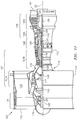
- FIG. 11 is a side cutaway illustration of a geared gas turbine engine.
- FIG. 1 illustrates an assembly 20 for rotational equipment with an axis 22 of rotation.
- An example of such rotational equipment is a gas turbine engine for an aircraft propulsion system, an exemplary embodiment of which is described below in further detail.
- the assembly 20 of the present disclosure is not limited to such an aircraft or gas turbine engine application.
- the assembly 20 may alternatively be configured with rotational equipment such as an industrial gas turbine engine, a wind turbine, a water turbine or any other apparatus in which a seal is provided between a stationary structure and a rotor.
- the assembly 20 of FIG. 1 includes a stationary structure 24 , a rotor structure 26 and a non-contact seal assembly 28 .
- the seal assembly 28 is mounted with the stationary structure 24 and configured to substantially seal an annular gap 30 between the stationary structure 24 and the rotor structure 26 as described below in further detail.
- the stationary structure 24 includes a seal carrier 32 .
- This seal carrier 32 may be a discrete, unitary annular body. Alternatively, the seal carrier 32 may be configured with another component/portion of the stationary structure 24 .
- the seal carrier 32 has an inner radial seal carrier surface 34 .
- This seal carrier surface 34 may be substantially cylindrical, and extends circumferentially around and faces towards the axis 22 .
- the seal carrier surface 34 at least partially forms a bore in the stationary structure 24 .
- This bore is sized to receive the seal assembly 28 , which may be fixedly attached to the seal carrier 32 by, for example, a press fit connection between the seal assembly 28 and the seal carrier surface 34 .
- the seal assembly 28 may also or alternatively be fixedly attached to the seal carrier 32 using one or more other techniques/devices.
- the rotor structure 26 includes a seal land 36 .
- This seal land 36 may be a discrete, unitary annular body. Alternatively, the seal land 36 may be configured with another component/portion of the rotor structure 26 .
- the seal land 36 has an outer radial seal land surface 38 .
- This seal land surface 38 may be substantially cylindrical, and extends circumferentially around and faces away from the axis 22 .
- the seal land surface 38 is disposed to face towards and is axially aligned with the seal carrier surface 34 . While FIG. 1 illustrates the seal land surface 38 and the seal carrier surface 34 with approximately equal axial lengths along the axis 22 , the seal land surface 38 may alternatively be longer or shorter than the seal carrier surface 34 in other embodiments.
- the seal assembly 28 includes a primary seal device 40 and one or more secondary seal devices 42 .
- the seal assembly 28 also includes one or more additional components for positioning, supporting and/or mounting one or more of the seal devices with the stationary structure 24 .
- the seal assembly 28 of FIG. 1 for example, includes a first ring structure 44 configured for positioning, supporting and/or mounting the secondary seal devices 42 relative to the primary seal device 40 .
- This first ring structure 44 may also be configured for axially positioning and/or supporting a first end surface 46 of the primary seal device 40 relative to the stationary structure 24 .
- a second ring structure 48 e.g., a scalloped support ring/plate
- a second ring structure 48 configured for axially positioning and/or supporting a second end surface 50 of the primary seal device 40 relative to the stationary structure 24 .
- the second ring structure 48 may be omitted where, for example, the second end surface 50 of the primary seal device 40 is abutted against another component/portion of the stationary structure 24 (e.g., an annular or castellated shoulder) or otherwise axially positioned/secured with the stationary structure 24 .
- the primary seal device 40 is configured as an annular non-contact seal device and, more particularly, a hydrostatic non-contact seal device.
- a hydrostatic non-contact seal device is a HALOTM type seal; however, the primary seal device 40 of the present disclosure is not limited to the foregoing exemplary hydrostatic non-contact seal device.
- the primary seal device 40 includes a seal base 52 , a plurality of seal shoes 54 , a plurality of spring elements 56 .
- the primary seal device 40 also includes a plurality of elements 58 A and 58 B (generally referred to as “ 58 ”) configured to restrict relative movement between the seal shoes 54 and the seal base 52 as described below in further detail.
- the seal base 52 is configured as an annular full hoop body (see FIG. 2 ), which extends circumferentially around the axis 22 .
- the seal base 52 is configured to circumscribe and support the seal shoes 54 as well as the spring elements 56 .
- the seal base 52 extends axially along the axis 22 between and forms the first end surface 46 and the second end surface 50 .
- the seal base 52 extends radially between an inner radial base side 60 and an outer radial base side 62 .
- the outer radial base side 62 radially engages (e.g., is press fit against) the stationary structure 24 and, more particularly, the seal carrier surface 34 (see FIG. 1 ).
- the seal shoes 54 are configured as arcuate bodies and arranged circumferentially about the axis 22 in an annular array. This annular array of the seal shoes 54 extends circumferentially around the axis 22 , thereby forming an inner bore at an inner radial side 64 of the primary seal device 40 . As best seen in FIG. 1 , the inner bore is sized to receive the seal land 36 , where the rotor structure 26 projects axially through (or into) the inner bore formed by the seal shoes 54 .
- each of the seal shoes 54 extends radially from the inner radial side 64 of the primary seal device 40 to an outer radial surface 66 of that seal shoe 54 .
- Each of the seal shoes 54 extends circumferentially around the axis 22 between opposing first and second circumferential sides 68 and 70 of that seal shoe 54 .
- each of the seal shoes 54 extends axially along the axis 22 between a first shoe end 72 and a second shoe end 74 .
- the first shoe end 72 may be axially offset from and project axially away from the first end surface 46 .
- the second shoe end 74 may be axially aligned with the second end surface 50 .
- the seal shoes 54 of the present disclosure are not limited to such exemplary relationships.
- Each of the seal shoes 54 includes an arcuate end surface 76 generally at (e.g., on, adjacent or proximate) the first shoe end 72 .
- these arcuate end surfaces 76 collectively form a generally annular (but circumferentially segmented) end surface 78 configured for sealingly engaging with the secondary seal devices 42 ; see FIG. 1 .
- the seal shoes 54 of the present disclosure are not limited to the foregoing exemplary configuration.
- Each of the seal shoes 54 includes one or more arcuate protrusions, which collectively form one or more (e.g., a plurality of axially spaced) generally annular (e.g., circumferentially segmented) ribs 80 at the inner radial side 64 . Distal inner radial ends of one or more of these ribs 80 are configured to be arranged in close proximity with (but not touch) and thereby sealingly mate with the seal land surface 38 in a non-contact manner (see FIG. 1 ), where the rotor structure 26 project axially through (or into) the inner bore formed by the seal shoes 54 .
- each of the ribs 80 has the same radial height. In other embodiments, however, one or more of the ribs 80 may have a different radial height than at least another one of the ribs 80 .
- the spring elements 56 are arranged circumferentially about the axis 22 in an annular array. Referring again to FIGS. 3 and 4 , the spring elements 56 are also arranged radially between the seal shoes 54 and the seal base 52 . Each of the spring elements 56 is configured to moveably and resiliently connect a respective one of the seal shoes 54 to the seal base 52 .
- the spring element 56 of FIG. 4 includes first and second mounts 82 and 84 (e.g., radial fingers/projections) and one or more spring beams 86 .
- the first mount 82 is connected to a respective one of the seal shoes 54 at (e.g., on, adjacent or proximate) the first circumferential side 68 , where the opposing second circumferential side 70 of that seal shoe 54 is free floating.
- the second mount 84 is connected to the seal base 52 , and is generally circumferentially aligned with or near the second circumferential side 70 .
- the second mount 84 is therefore disposed a circumferential distance from the first mount 82 .
- the spring beams 86 are configured as resilient, biasing members of the primary seal device 40 .
- the spring beams 86 of FIG. 4 are generally configured as cantilevered-leaf springs. These spring beams 86 are radially stacked and spaced apart with one another so as to form a four bar linkage with the first mount 82 and the second mount 84 . More particularly, each of the spring beams 86 is connected to the first mount 82 and the second mount 84 .
- Each of the spring beams 86 extends longitudinally (e.g., in a generally circumferential direction relative to the axis 22 ) between and to the first mount 82 and the second mount 84 .
- the spring beams 86 of FIG. 4 may thereby laterally overlap a major circumferential portion (e.g., ⁇ 65-95%) of the respective seal shoe 54 .
- rotation of the rotor structure 26 may develop aerodynamic forces and apply a fluid pressure to the seal shoes 54 causing each seal shoe 54 to respectively move radially relative to the seal land surface 38 .
- the fluid velocity may increase as a gap between a respective seal shoe 54 and the seal land surface 38 increases, thus reducing pressure in the gap and drawing the seal shoe 54 radially inwardly toward the seal land surface 38 .
- the velocity may decrease and the pressure may increase within the gap, thus, forcing the seal shoe 54 radially outwardly from the seal land surface 38 .
- the respective spring element 56 may deflect and move with the seal shoe 54 to enable provision of a primary seal of the gap between the seal land surface 38 and ribs 80 within predetermined design tolerances.
- each of the elements 58 is configured with the primary seal device 40 to restrict the relative movement between the seal shoes 54 and the seal base 52 .
- Each of the elements 58 in the embodiment of FIGS. 5 and 6 is configured to restrict (e.g., limit/stop) radial outward movement of a respective one of the seal shoes 54 .
- the first element 58 A is arranged radially between the first mount 82 and the seal base 52 .
- the second element 58 B is arranged radially between the second mount 84 and a respective one of the seal shoes 54 .
- the respective seal shoe 54 may move radially up and down as described above.
- FIG. 5 illustrates the seal shoe 54 in a radially down position.
- FIG. 6 illustrates the seal shown in a radial up position.
- the first element 58 A and/or the second element 58 B operate as stops/bumpers.
- first element 58 A radially engages (e.g., contacts) both the first mount 82 and the seal base 52 .
- second element 58 B radially engages (e.g., contacts) both the second mount 84 and the seal shoe 54 .
- first element 58 A and/or the second element 58 B provide impediments to further radial outward movement of the mounts 82 and 84 and, thereby, the seal shoe 54 .
- the seal shoe 54 may move radially a first distance 88 (e.g., has a first magnitude of radial movement) between a fully radial down position (see FIG. 7A ) and a nominal fully radial up position (see FIGS. 6 and 7B ).
- This radial movement of the seal shoe 54 enables the primary seal device 40 to accommodate a certain degree of movement between the stationary structure 24 and the rotor structure 26 , which movement may be cause by thermal expansion and/or vibrations in the stationary structure 24 and/or the rotor structure 26 .
- each element 58 may be configured to change (e.g., deform) from a nominal (e.g., undamaged and/or uncompressed) configuration shown in FIG. 8A to an off-nominal (e.g., damaged and/or compressed) configuration shown in FIG.
- a pressure (and/or rotor contact) force on the seal shoe 54 may be so great as to deform (e.g., crush) the seal element(s) 58 between the components 52 and 82 , 54 and 84 .
- the seal shoe 54 may move radially a second distance 90 (e.g., has a second magnitude of radial movement) between the fully radial down position and an off-nominal fully radial up position, where the second distance 90 is greater than the first distance 88 .
- each of the elements 58 may have various configurations and/or constructions to provide the progressive radial movement restriction described above.
- each element 58 may be configured as an open and/or closed cell porous body (e.g., generally shown in FIG. 5 ); e.g., a body with a honeycomb structure. With such a configuration, each element 58 may have an undamaged and/or uncompressed and/or uncrumpled configuration during the nominal operation. Each element 58 may have a damaged and/or compressed and/or crumpled configuration during the off-nominal operation.
- each element 58 may be configured as a replaceable component (e.g., a throwaway component) of the primary seal device 40 .
- an element 58 may no longer be capable of self-returning to its nominal configuration. Therefore, that element 58 may be removed (e.g., by removing a braze/bond joint) and replacing the removed element 58 with a new/reconditioned element 58 .
- Each element 58 may be formed from the same material as other components of the primary seal device 40 ; e.g., metal. Alternatively, each element 58 may be formed from a different (e.g., less stiff, more malleable, more ductile, etc.) material from the other components of the primary seal device 40 . Examples of suitable element materials include, but are not limited to, metals, composites and polymers. Of course, the elements 58 of the present disclosure are not limited to the foregoing exemplary configurations, constructions and materials.
- the first element 58 A is connected to a distal radial outer end of the first mount 82 .
- the second element 58 B is connected to a distal radial inner end of the second mount 84 .
- each element 58 A, 58 B may be formed integral with the respective mount 82 , 84 .
- each element 58 A, 58 B may be brazed, welded and/or otherwise bonded to the respective mount 82 , 84 .
- each element 58 A, 58 B may be mechanically fastened to the respective mount 82 , 84 .
- the first element 58 A is connected to the seal base 52 .
- the second element 58 B is connected to a respective one of the seal shoes 54 .
- each element 58 A, 58 B may be formed integral with the respective component 52 , 54 .
- each element 58 A, 58 B may be brazed, welded and/or otherwise bonded to the respective component 52 , 54 .
- each element 58 A, 58 B may be mechanically fastened to the respective component 52 , 54 .
- the first element 58 A is operable to alternately radially engage with and disengage from the first mount 82 .
- the second element 58 B is operable to alternately radially engage with and disengage from the second mount 84 .
- each of the seal shoes 54 is associated with a pair of elements 58 .
- one or more of the seal shoes 54 may each be associated with the first element 58 A or the second element 58 B.
- one or more of the seal shoes 54 may each be associated with more than two elements 58 .
- opposing and engageable first elements 58 A may be respectively connected to the first mount 82 and the seal base 52 .
- opposing and engageable second elements 58 B may be respectively connected to both the second mount 84 and the seal shoe 54 .
- the first element 58 A is operable to alternately radially engage with and disengage from the other first element 58 A.
- the second element 58 B is operable to alternately radially engage with and disengage from the other second element 58 B.
- fluid e.g., gas
- the secondary seal devices 42 therefore are provided to seal off these passages 92 and, thereby, further and more completely seal the annular gap 30 .
- Each of the secondary seal devices 42 may be configured as a ring seal element such as, but not limited to, a split ring. Alternatively, one or more of the secondary seal devices 42 may be configured as a full hoop body ring, an annular brush seal or any other suitable ring-type seal.
- the secondary seal devices 42 of FIG. 1 are arranged together in an axial stack. In this stack, each of the secondary seal devices 42 axially engages (e.g., contacts) another adjacent one of the secondary seal devices 42 .
- the stack of the secondary seal devices 42 is arranged with the first ring structure 44 , which positions and mounts the secondary seal devices 42 with the stationary structure 24 adjacent the primary seal device 40 .
- the stack of the secondary seal devices 42 is operable to axially engage and form a seal between the end surface 78 of the array of the seal shoes 54 and an annular surface 94 of the first ring structure 44 .
- the first ring structure 44 may include a secondary seal device support ring 96 and a retention ring 98 .
- the support ring 96 is configured with an annular full hoop body, which extends circumferentially around the axis 22 .
- the support ring 96 includes the annular surface, and is disposed axially adjacent and engaged with the seal base 52 .
- the retention ring 98 is configured with an annular full hoop body, which extends circumferentially around the axis 22 .
- the retention ring 98 is disposed axially adjacent and engaged with the support ring 96 , thereby capturing the stack of the secondary seal devices 42 within an annular channel formed between the rings 96 and 98 .
- the stack of the secondary seal devices 42 may also or alternatively be attached to one of the rings 96 and 98 by, for example, a press fit connection and/or otherwise.
- FIG. 11 illustrates one such type and configuration of the rotational equipment—a geared turbofan gas turbine engine 100 .
- a turbine engine includes various stationary structures (e.g., bearing supports, hubs, cases, etc.) as well as various rotors (e.g., rotor disks, shafts, shaft assemblies, etc.) as described below, where the stationary structure 24 and the rotor structure 26 can respectively be configured as anyone of the foregoing structures in the turbine engine 100 of FIG. 11 , or other structures not mentioned herein.
- the turbine engine 100 of FIG. 11 extends along an axis (e.g., the axis 22 or rotation) between an upstream airflow inlet 102 and a downstream airflow exhaust 104 .
- the turbine engine 100 includes a fan section 106 , a compressor section 107 , a combustor section 108 and a turbine section 109 .
- the compressor section 107 includes a low pressure compressor (LPC) section 107 A and a high pressure compressor (HPC) section 107 B.
- the turbine section 109 includes a high pressure turbine (HPT) section 109 A and a low pressure turbine (LPT) section 109 B.
- the engine sections 106 - 109 are arranged sequentially along the axis 22 within an engine housing 110 .
- This housing 110 includes an inner case 112 (e.g., a core case) and an outer case 114 (e.g., a fan case).
- the inner case 112 may house one or more of the engine sections 107 - 109 ; e.g., an engine core.
- the outer case 114 may house at least the fan section 106 .
- Each of the engine sections 106 , 107 A, 107 B, 109 A and 109 B includes a respective rotor 116 - 120 .
- Each of these rotors 116 - 120 includes a plurality of rotor blades arranged circumferentially around and connected to one or more respective rotor disks.
- the rotor blades may be formed integral with or mechanically fastened, welded, brazed, adhered and/or otherwise attached to the respective rotor disk(s).
- the fan rotor 116 is connected to a gear train 122 , for example, through a fan shaft 124 .
- the gear train 122 and the LPC rotor 117 are connected to and driven by the LPT rotor 120 through a low speed shaft 125 .
- the HPC rotor 118 is connected to and driven by the HPT rotor 119 through a high speed shaft 126 .
- the shafts 124 - 126 are rotatably supported by a plurality of bearings 128 . Each of these bearings 128 is connected to the engine housing 110 by at least one stationary structure such as, for example, an annular support strut.
- This air is directed through the fan section 106 and into a core gas path 130 and a bypass gas path 132 .
- the core gas path 130 extends sequentially through the engine sections 107 - 109 ; e.g., an engine core.
- the air within the core gas path 130 may be referred to as “core air”.
- the bypass gas path 132 extends through a bypass duct, which bypasses the engine core.
- the air within the bypass gas path 132 may be referred to as “bypass air”.
- the core air is compressed by the compressor rotors 117 and 118 and directed into a combustion chamber 134 of a combustor in the combustor section 108 .
- Fuel is injected into the combustion chamber 134 and mixed with the compressed core air to provide a fuel-air mixture.
- This fuel air mixture is ignited and combustion products thereof flow through and sequentially cause the turbine rotors 119 and 120 to rotate.
- the rotation of the turbine rotors 119 and 120 respectively drive rotation of the compressor rotors 118 and 117 and, thus, compression of the air received from a core airflow inlet.
- the rotation of the turbine rotor 120 also drives rotation of the fan rotor 116 , which propels bypass air through and out of the bypass gas path 132 .
- the propulsion of the bypass air may account for a majority of thrust generated by the turbine engine 100 , e.g., more than seventy-five percent (75%) of engine thrust.
- the turbine engine 100 of the present disclosure is not limited to the foregoing exemplary thrust ratio.
- the assembly 20 may be included in various aircraft and industrial turbine engines other than the one described above as well as in other types of rotational equipment; e.g., wind turbines, water turbines, rotary engines, etc.
- the assembly 20 may be included in a geared turbine engine where a gear train connects one or more shafts to one or more rotors in a fan section, a compressor section and/or any other engine section.
- the assembly 20 may be included in a turbine engine configured without a gear train.
- the assembly 20 may be included in a geared or non-geared turbine engine configured with a single spool, with two spools (e.g., see FIG. 11 ), or with more than two spools.
- the turbine engine may be configured as a turbofan engine, a turbojet engine, a propfan engine, a pusher fan engine or any other type of turbine engine.
- the present invention therefore is not limited to any particular types or configurations of turbine engines or rotational equipment.
Landscapes
- Engineering & Computer Science (AREA)
- General Engineering & Computer Science (AREA)
- Mechanical Engineering (AREA)
- Chemical & Material Sciences (AREA)
- Combustion & Propulsion (AREA)
- Mechanical Sealing (AREA)
Abstract
Description
Claims (20)
Priority Applications (1)
| Application Number | Priority Date | Filing Date | Title |
|---|---|---|---|
| US16/541,898 US10697550B2 (en) | 2017-07-17 | 2019-08-15 | Non-contact seal with progressive radial stop(s) |
Applications Claiming Priority (2)
| Application Number | Priority Date | Filing Date | Title |
|---|---|---|---|
| US15/651,081 US10422431B2 (en) | 2017-07-17 | 2017-07-17 | Non-contact seal with progressive radial stop(s) |
| US16/541,898 US10697550B2 (en) | 2017-07-17 | 2019-08-15 | Non-contact seal with progressive radial stop(s) |
Related Parent Applications (1)
| Application Number | Title | Priority Date | Filing Date |
|---|---|---|---|
| US15/651,081 Continuation US10422431B2 (en) | 2017-07-17 | 2017-07-17 | Non-contact seal with progressive radial stop(s) |
Publications (2)
| Publication Number | Publication Date |
|---|---|
| US20190368615A1 US20190368615A1 (en) | 2019-12-05 |
| US10697550B2 true US10697550B2 (en) | 2020-06-30 |
Family
ID=62186287
Family Applications (2)
| Application Number | Title | Priority Date | Filing Date |
|---|---|---|---|
| US15/651,081 Active 2037-08-15 US10422431B2 (en) | 2017-07-17 | 2017-07-17 | Non-contact seal with progressive radial stop(s) |
| US16/541,898 Active US10697550B2 (en) | 2017-07-17 | 2019-08-15 | Non-contact seal with progressive radial stop(s) |
Family Applications Before (1)
| Application Number | Title | Priority Date | Filing Date |
|---|---|---|---|
| US15/651,081 Active 2037-08-15 US10422431B2 (en) | 2017-07-17 | 2017-07-17 | Non-contact seal with progressive radial stop(s) |
Country Status (2)
| Country | Link |
|---|---|
| US (2) | US10422431B2 (en) |
| EP (1) | EP3431837B1 (en) |
Cited By (2)
| Publication number | Priority date | Publication date | Assignee | Title |
|---|---|---|---|---|
| US20220268166A1 (en) * | 2021-02-19 | 2022-08-25 | Raytheon Technologies Corporation | Non-contacting seal assembly with internal coating |
| US20240328515A1 (en) * | 2023-03-31 | 2024-10-03 | Raytheon Technologies Corporation | Non-contact seal with seal device axial locator(s) |
Families Citing this family (20)
| Publication number | Priority date | Publication date | Assignee | Title |
|---|---|---|---|---|
| US10184347B1 (en) * | 2017-07-18 | 2019-01-22 | United Technologies Corporation | Non-contact seal with resilient biasing element(s) |
| US10746039B2 (en) * | 2017-09-25 | 2020-08-18 | United Technologies Corporation | Hydrostatic seal pinned cartridge |
| US11421543B2 (en) * | 2018-11-28 | 2022-08-23 | Raytheon Technologies Corporation | Hydrostatic seal with asymmetric beams for anti-tipping |
| US11674402B2 (en) | 2018-11-28 | 2023-06-13 | Raytheon Technologies Corporation | Hydrostatic seal with non-parallel beams for anti-tipping |
| US10968763B2 (en) * | 2019-02-01 | 2021-04-06 | Raytheon Technologies Corporation | HALO seal build clearance methods |
| US11415227B2 (en) | 2019-08-21 | 2022-08-16 | Raytheon Technologies Corporation | Non-contact seal assembly with chamfered seal shoe |
| US11193593B2 (en) | 2019-09-03 | 2021-12-07 | Raytheon Technologies Corporation | Hydrostatic seal |
| US11384658B1 (en) | 2021-08-19 | 2022-07-12 | Pratt & Whitney Canada Corp. | Deformable bumper for a rotating structure of a turbine engine |
| US12006829B1 (en) | 2023-02-16 | 2024-06-11 | General Electric Company | Seal member support system for a gas turbine engine |
| US12486779B2 (en) | 2023-03-08 | 2025-12-02 | General Electric Company | Seal support assembly for a turbine engine |
| FR3146929B1 (en) * | 2023-03-23 | 2025-07-11 | Safran Aircraft Engines | Stator assembly for an aircraft turbomachine |
| US12372002B2 (en) | 2023-03-24 | 2025-07-29 | General Electric Company | Seal support assembly for a turbine engine |
| US12116896B1 (en) | 2023-03-24 | 2024-10-15 | General Electric Company | Seal support assembly for a turbine engine |
| US12416243B2 (en) | 2023-03-24 | 2025-09-16 | General Electric Company | Seal support assembly for a turbine engine |
| US12241375B2 (en) | 2023-03-24 | 2025-03-04 | General Electric Company | Seal support assembly for a turbine engine |
| US12215587B2 (en) | 2023-03-24 | 2025-02-04 | General Electric Company | Seal support assembly for a turbine engine |
| US12421861B2 (en) | 2023-03-24 | 2025-09-23 | General Electric Company | Seal support assembly for a turbine engine |
| US12595745B2 (en) | 2023-03-24 | 2026-04-07 | General Electric Company | Seal support assembly for a turbine engine |
| US12215588B2 (en) | 2023-03-27 | 2025-02-04 | General Electric Company | Seal assembly for a gas turbine engine |
| US12326089B2 (en) | 2023-04-24 | 2025-06-10 | General Electric Company | Seal assembly for a gas turbine engine |
Citations (22)
| Publication number | Priority date | Publication date | Assignee | Title |
|---|---|---|---|---|
| EP0826457A1 (en) | 1996-08-14 | 1998-03-04 | ROLLS-ROYCE plc | A method of drilling a hole in a workpiece |
| US6428009B2 (en) | 2000-04-03 | 2002-08-06 | John F. Justak | Robust hydrodynamic brush seal |
| US7182345B2 (en) | 2003-05-01 | 2007-02-27 | Justak John F | Hydrodynamic brush seal |
| US7410173B2 (en) | 2003-05-01 | 2008-08-12 | Justak John F | Hydrodynamic brush seal |
| US7816625B2 (en) | 2003-10-06 | 2010-10-19 | Siemens Aktiengesellschaft | Method for the production of a hole and device |
| US7896352B2 (en) | 2003-05-01 | 2011-03-01 | Justak John F | Seal with stacked sealing elements |
| US8002285B2 (en) | 2003-05-01 | 2011-08-23 | Justak John F | Non-contact seal for a gas turbine engine |
| US8172232B2 (en) | 2003-05-01 | 2012-05-08 | Advanced Technologies Group, Inc. | Non-contact seal for a gas turbine engine |
| US20120223483A1 (en) | 2011-03-04 | 2012-09-06 | General Electric Company | Aerodynamic Seal Assemblies for Turbo-Machinery |
| US20130234399A1 (en) | 2003-05-01 | 2013-09-12 | John F. Justak | Self-adjusting non-contact seal |
| US20140008871A1 (en) | 2012-07-06 | 2014-01-09 | General Electric Company | Aerodynamic seals for rotary machine |
| US20140062024A1 (en) | 2012-07-31 | 2014-03-06 | General Electric Company | Film riding seals for rotary machines |
| US20140119912A1 (en) | 2012-10-31 | 2014-05-01 | General Electric Company | Film riding aerodynamic seals for rotary machines |
| US20140117624A1 (en) | 2012-10-31 | 2014-05-01 | General Electric Company | Pressure actuated film riding seals for turbo machinery |
| US20160010480A1 (en) | 2014-07-08 | 2016-01-14 | General Electric Company | Film riding seal assembly for turbomachinery |
| US20160108750A1 (en) | 2014-10-17 | 2016-04-21 | United Technologies Corporation | Circumferential seal with seal dampening elements |
| US20160115805A1 (en) | 2014-10-28 | 2016-04-28 | General Electric Company | Flexible film-riding seal |
| US20160130963A1 (en) | 2014-11-07 | 2016-05-12 | United Technologies Corporation | Gas turbine engine and seal assembly therefore |
| US9434025B2 (en) | 2011-07-19 | 2016-09-06 | Pratt & Whitney Canada Corp. | Laser drilling methods of shallow-angled holes |
| US20160263707A1 (en) | 2011-07-19 | 2016-09-15 | Pratt & Whitney Canada Corp. | Laser drilling methods of shallow-angled hole |
| US9676058B2 (en) | 2014-01-27 | 2017-06-13 | General Electric Company | Method and system for detecting drilling progress in laser drilling |
| US20180058240A1 (en) | 2016-09-01 | 2018-03-01 | United Technologies Corporation | Floating non-contact seal vertical lip |
-
2017
- 2017-07-17 US US15/651,081 patent/US10422431B2/en active Active
-
2018
- 2018-05-15 EP EP18172485.7A patent/EP3431837B1/en active Active
-
2019
- 2019-08-15 US US16/541,898 patent/US10697550B2/en active Active
Patent Citations (22)
| Publication number | Priority date | Publication date | Assignee | Title |
|---|---|---|---|---|
| EP0826457A1 (en) | 1996-08-14 | 1998-03-04 | ROLLS-ROYCE plc | A method of drilling a hole in a workpiece |
| US6428009B2 (en) | 2000-04-03 | 2002-08-06 | John F. Justak | Robust hydrodynamic brush seal |
| US7182345B2 (en) | 2003-05-01 | 2007-02-27 | Justak John F | Hydrodynamic brush seal |
| US7410173B2 (en) | 2003-05-01 | 2008-08-12 | Justak John F | Hydrodynamic brush seal |
| US7896352B2 (en) | 2003-05-01 | 2011-03-01 | Justak John F | Seal with stacked sealing elements |
| US8002285B2 (en) | 2003-05-01 | 2011-08-23 | Justak John F | Non-contact seal for a gas turbine engine |
| US8172232B2 (en) | 2003-05-01 | 2012-05-08 | Advanced Technologies Group, Inc. | Non-contact seal for a gas turbine engine |
| US20130234399A1 (en) | 2003-05-01 | 2013-09-12 | John F. Justak | Self-adjusting non-contact seal |
| US7816625B2 (en) | 2003-10-06 | 2010-10-19 | Siemens Aktiengesellschaft | Method for the production of a hole and device |
| US20120223483A1 (en) | 2011-03-04 | 2012-09-06 | General Electric Company | Aerodynamic Seal Assemblies for Turbo-Machinery |
| US9434025B2 (en) | 2011-07-19 | 2016-09-06 | Pratt & Whitney Canada Corp. | Laser drilling methods of shallow-angled holes |
| US20160263707A1 (en) | 2011-07-19 | 2016-09-15 | Pratt & Whitney Canada Corp. | Laser drilling methods of shallow-angled hole |
| US20140008871A1 (en) | 2012-07-06 | 2014-01-09 | General Electric Company | Aerodynamic seals for rotary machine |
| US20140062024A1 (en) | 2012-07-31 | 2014-03-06 | General Electric Company | Film riding seals for rotary machines |
| US20140117624A1 (en) | 2012-10-31 | 2014-05-01 | General Electric Company | Pressure actuated film riding seals for turbo machinery |
| US20140119912A1 (en) | 2012-10-31 | 2014-05-01 | General Electric Company | Film riding aerodynamic seals for rotary machines |
| US9676058B2 (en) | 2014-01-27 | 2017-06-13 | General Electric Company | Method and system for detecting drilling progress in laser drilling |
| US20160010480A1 (en) | 2014-07-08 | 2016-01-14 | General Electric Company | Film riding seal assembly for turbomachinery |
| US20160108750A1 (en) | 2014-10-17 | 2016-04-21 | United Technologies Corporation | Circumferential seal with seal dampening elements |
| US20160115805A1 (en) | 2014-10-28 | 2016-04-28 | General Electric Company | Flexible film-riding seal |
| US20160130963A1 (en) | 2014-11-07 | 2016-05-12 | United Technologies Corporation | Gas turbine engine and seal assembly therefore |
| US20180058240A1 (en) | 2016-09-01 | 2018-03-01 | United Technologies Corporation | Floating non-contact seal vertical lip |
Cited By (3)
| Publication number | Priority date | Publication date | Assignee | Title |
|---|---|---|---|---|
| US20220268166A1 (en) * | 2021-02-19 | 2022-08-25 | Raytheon Technologies Corporation | Non-contacting seal assembly with internal coating |
| US20240328515A1 (en) * | 2023-03-31 | 2024-10-03 | Raytheon Technologies Corporation | Non-contact seal with seal device axial locator(s) |
| US12264742B2 (en) * | 2023-03-31 | 2025-04-01 | Rtx Corporation | Non-contact seal with seal device axial locator(s) |
Also Published As
| Publication number | Publication date |
|---|---|
| US10422431B2 (en) | 2019-09-24 |
| US20190368615A1 (en) | 2019-12-05 |
| EP3431837B1 (en) | 2020-08-05 |
| US20190017607A1 (en) | 2019-01-17 |
| EP3431837A1 (en) | 2019-01-23 |
Similar Documents
| Publication | Publication Date | Title |
|---|---|---|
| US10697550B2 (en) | Non-contact seal with progressive radial stop(s) | |
| EP3431838B1 (en) | Non-contact seal with resilient biasing element(s) | |
| US10563532B2 (en) | Non-contact seal with monolithic/unitary carrier structure | |
| US10208615B2 (en) | Seal shoe for a hydrostatic non-contact seal device | |
| US10060535B2 (en) | Shaped spring element for a non-contact seal device | |
| EP3783250B1 (en) | Non-contact seal asembly with chamfered seal shoe | |
| EP3889475B1 (en) | Non-contact seal for rotational equipment with radial through-hole | |
| US10830081B2 (en) | Non-contact seal with non-straight spring beam(s) | |
| US10641180B2 (en) | Hydrostatic non-contact seal with varied thickness beams | |
| US10337621B2 (en) | Hydrostatic non-contact seal with weight reduction pocket | |
| US10718270B2 (en) | Hydrostatic non-contact seal with dual material | |
| EP3428489B1 (en) | Hydrostatic non-contact seal with seal carrier elimination | |
| US10731761B2 (en) | Hydrostatic non-contact seal with offset outer ring | |
| US11619309B2 (en) | Non-contact seal for rotational equipment with axially expended seal shoes |
Legal Events
| Date | Code | Title | Description |
|---|---|---|---|
| FEPP | Fee payment procedure |
Free format text: ENTITY STATUS SET TO UNDISCOUNTED (ORIGINAL EVENT CODE: BIG.); ENTITY STATUS OF PATENT OWNER: LARGE ENTITY |
|
| STPP | Information on status: patent application and granting procedure in general |
Free format text: NON FINAL ACTION MAILED |
|
| STPP | Information on status: patent application and granting procedure in general |
Free format text: RESPONSE TO NON-FINAL OFFICE ACTION ENTERED AND FORWARDED TO EXAMINER |
|
| STPP | Information on status: patent application and granting procedure in general |
Free format text: NOTICE OF ALLOWANCE MAILED -- APPLICATION RECEIVED IN OFFICE OF PUBLICATIONS |
|
| AS | Assignment |
Owner name: UNITED TECHNOLOGIES CORPORATION, CONNECTICUT Free format text: ASSIGNMENT OF ASSIGNORS INTEREST;ASSIGNORS:CHUONG, CONWAY;WILSON, ROSS;REEL/FRAME:052708/0053 Effective date: 20170717 |
|
| STCF | Information on status: patent grant |
Free format text: PATENTED CASE |
|
| AS | Assignment |
Owner name: RAYTHEON TECHNOLOGIES CORPORATION, MASSACHUSETTS Free format text: CHANGE OF NAME;ASSIGNOR:UNITED TECHNOLOGIES CORPORATION;REEL/FRAME:054062/0001 Effective date: 20200403 |
|
| AS | Assignment |
Owner name: RAYTHEON TECHNOLOGIES CORPORATION, CONNECTICUT Free format text: CORRECTIVE ASSIGNMENT TO CORRECT THE AND REMOVE PATENT APPLICATION NUMBER 11886281 AND ADD PATENT APPLICATION NUMBER 14846874. TO CORRECT THE RECEIVING PARTY ADDRESS PREVIOUSLY RECORDED AT REEL: 054062 FRAME: 0001. ASSIGNOR(S) HEREBY CONFIRMS THE CHANGE OF ADDRESS;ASSIGNOR:UNITED TECHNOLOGIES CORPORATION;REEL/FRAME:055659/0001 Effective date: 20200403 |
|
| AS | Assignment |
Owner name: RTX CORPORATION, CONNECTICUT Free format text: CHANGE OF NAME;ASSIGNOR:RAYTHEON TECHNOLOGIES CORPORATION;REEL/FRAME:064714/0001 Effective date: 20230714 |
|
| MAFP | Maintenance fee payment |
Free format text: PAYMENT OF MAINTENANCE FEE, 4TH YEAR, LARGE ENTITY (ORIGINAL EVENT CODE: M1551); ENTITY STATUS OF PATENT OWNER: LARGE ENTITY Year of fee payment: 4 |