EP3782879B1 - Motor-vehicle lattice frame - Google Patents
Motor-vehicle lattice frame Download PDFInfo
- Publication number
- EP3782879B1 EP3782879B1 EP19193174.0A EP19193174A EP3782879B1 EP 3782879 B1 EP3782879 B1 EP 3782879B1 EP 19193174 A EP19193174 A EP 19193174A EP 3782879 B1 EP3782879 B1 EP 3782879B1
- Authority
- EP
- European Patent Office
- Prior art keywords
- arm
- motor
- lattice frame
- beam element
- end portion
- Prior art date
- Legal status (The legal status is an assumption and is not a legal conclusion. Google has not performed a legal analysis and makes no representation as to the accuracy of the status listed.)
- Active
Links
- 239000000463 material Substances 0.000 claims description 21
- 239000000853 adhesive Substances 0.000 claims description 18
- 230000001070 adhesive effect Effects 0.000 claims description 18
- 238000004519 manufacturing process Methods 0.000 claims description 14
- 238000000034 method Methods 0.000 claims description 9
- 239000000654 additive Substances 0.000 claims description 8
- 230000000996 additive effect Effects 0.000 claims description 8
- 239000012790 adhesive layer Substances 0.000 claims description 8
- 230000008878 coupling Effects 0.000 claims description 5
- 238000010168 coupling process Methods 0.000 claims description 5
- 238000005859 coupling reaction Methods 0.000 claims description 5
- 125000006850 spacer group Chemical group 0.000 claims description 3
- 239000010410 layer Substances 0.000 description 3
- 229910052751 metal Inorganic materials 0.000 description 3
- 239000002184 metal Substances 0.000 description 3
- 238000004026 adhesive bonding Methods 0.000 description 2
- 238000010276 construction Methods 0.000 description 2
- 238000009826 distribution Methods 0.000 description 2
- 238000005516 engineering process Methods 0.000 description 2
- 230000005923 long-lasting effect Effects 0.000 description 2
- 229910000838 Al alloy Inorganic materials 0.000 description 1
- 239000003292 glue Substances 0.000 description 1
- 239000000843 powder Substances 0.000 description 1
Images


Classifications
-
- B—PERFORMING OPERATIONS; TRANSPORTING
- B62—LAND VEHICLES FOR TRAVELLING OTHERWISE THAN ON RAILS
- B62D—MOTOR VEHICLES; TRAILERS
- B62D23/00—Combined superstructure and frame, i.e. monocoque constructions
- B62D23/005—Combined superstructure and frame, i.e. monocoque constructions with integrated chassis in the whole shell, e.g. meshwork, tubes, or the like
-
- B—PERFORMING OPERATIONS; TRANSPORTING
- B33—ADDITIVE MANUFACTURING TECHNOLOGY
- B33Y—ADDITIVE MANUFACTURING, i.e. MANUFACTURING OF THREE-DIMENSIONAL [3-D] OBJECTS BY ADDITIVE DEPOSITION, ADDITIVE AGGLOMERATION OR ADDITIVE LAYERING, e.g. BY 3-D PRINTING, STEREOLITHOGRAPHY OR SELECTIVE LASER SINTERING
- B33Y80/00—Products made by additive manufacturing
-
- B—PERFORMING OPERATIONS; TRANSPORTING
- B62—LAND VEHICLES FOR TRAVELLING OTHERWISE THAN ON RAILS
- B62D—MOTOR VEHICLES; TRAILERS
- B62D21/00—Understructures, i.e. chassis frame on which a vehicle body may be mounted
-
- B—PERFORMING OPERATIONS; TRANSPORTING
- B62—LAND VEHICLES FOR TRAVELLING OTHERWISE THAN ON RAILS
- B62D—MOTOR VEHICLES; TRAILERS
- B62D27/00—Connections between superstructure or understructure sub-units
- B62D27/02—Connections between superstructure or understructure sub-units rigid
- B62D27/023—Assembly of structural joints
-
- B—PERFORMING OPERATIONS; TRANSPORTING
- B60—VEHICLES IN GENERAL
- B60Y—INDEXING SCHEME RELATING TO ASPECTS CROSS-CUTTING VEHICLE TECHNOLOGY
- B60Y2304/00—Optimising design; Manufacturing; Testing
- B60Y2304/05—Reducing production costs, e.g. by redesign
-
- B—PERFORMING OPERATIONS; TRANSPORTING
- B62—LAND VEHICLES FOR TRAVELLING OTHERWISE THAN ON RAILS
- B62D—MOTOR VEHICLES; TRAILERS
- B62D27/00—Connections between superstructure or understructure sub-units
- B62D27/02—Connections between superstructure or understructure sub-units rigid
- B62D27/026—Connections by glue bonding
Definitions
- the present invention relates in general to motor-vehicle frames and more specifically to a motor-vehicle lattice frame comprising:
- WO 2016/003982 A1 discloses a motor vehicle lattice frame structure according to the preamble of claim 1 comprising a plurality of structural nodes, each having a central body and at least one hollow arm protruding from the central body, and a plurality of beam elements connected to each other by means of the hollow protruding arms, said structural nodes being made using an additive manufacturing technique.
- the present invention is based on the requirement to provide a motor-vehicle lattice frame which has a rapid and low-cost production and assembly method, without thereby being less effective in performing the functions for which it is designed.
- An additional object of the invention is to provide a motor-vehicle lattice frame consisting of components suitable for producing different frame geometries.
- the invention relates to a motor-vehicle lattice frame of the type indicated at the beginning of the present description and also characterized in that at least one arm of one of the nodes has an end portion opposite to the central body having a channel conformation with an open cavity both at a front end of the arm and along one side of the arm.
- said end portion having a channel-shaped configuration includes two side flanges each extending along one side of the arm, at a respective side of said open cavity, so that said at least one arm has an ⁇ cross-section at said end portion.
- the beam element connected to said at least one arm with an ⁇ cross-section can include two end flanges arranged in abutment against said side flanges, so as to define a free space between the inner surface of the hollow arm and the beam element inserted into said channel-shaped end portion.
- said beam element is connected to said at least one arm with a channel-shaped end portion, only by the aid of an adhesive layer.
- additive manufacturing means a method, known in the art, in which an energy source is used, such as a laser or plasma beam, to selectively melt layers of metal or plastic powders or wires, of various sizes, so as to form - layer after layer - a metal or plastic component.
- an energy source such as a laser or plasma beam
- a device for making components using additive manufacturing is known from the document EP 3148784 A1 .
- the technology illustrated in this document is just an example, since different additive manufacturing technologies can be applied to make the motor-vehicle lattice frame according to the present invention.
- the attached drawings show preferred embodiments of a motor-vehicle lattice frame T according to the present invention.
- the present invention may relate to any type of motor-vehicle frame, for example, a frame of a motor-vehicle structure, or a frame for supporting a component installed on the motor-vehicle.
- the motor-vehicle lattice frame T comprises a plurality of structural nodes N1, N2 each having a central body 1 from which at least two hollow arms 2, 3, 4, 30 protrude.
- the lattice frame T also includes a multitude of beam elements 5, 6, 11, 27 which are connected to each other by means of the protruding arms 2, 3, 4, 30.
- the beam elements connected to the respective arms of the nodes can have cross-sections with different shapes (for example, quadrangular or circular).
- the structural nodes N1, N2 of the lattice frame T are obtained with a construction technique of "additive manufacturing".
- additive manufacturing By producing the structural nodes by means of an additive manufacturing technique it is possible to obtain numerous advantages with respect to the traditional production methods, among which, preparing components with complex geometries without incurring penalties in terms of time or cost with respect to the production of components with more simple geometries.
- the structural nodes can be made of metal or plastic material, while the beam elements connected to each other by means of the structural nodes, can be made, for example, of aluminium alloy.
- FIG. 2 shows a perspective view of a first embodiment of a motor-vehicle structural node N1.
- each structural node which together with the beam elements composes the lattice frame T, includes a central body 1 and a plurality of hollow arms 2, 3, 4, 30 protruding from the central body 1.
- the hollow arms can be arranged around the central body according to multiple configurations so as to achieve the required geometry of the frame.
- At least one arm 2 of one of the nodes has an end portion opposite the central body 1 which includes a C-channel shape with an open cavity both at a front end 12 of the arm 2 and along a side 13 of the arm 2 ( Figures 2-4 ).
- the C-channel conformation with an open cavity is arranged to receive a respective beam element 6 therein, intended to be connected at one of its opposite ends to another structural node.
- the beam element 6 is connected to the arm 2 only by the aid of an adhesive layer. Still with reference to Figures 2-4 , in order to produce the bonding between the arm 2 and the beam element 6, the C-channel shaped end portion includes two opposite side walls 14 on which at least one opening 7 is made to allow the passage of the adhesive layer.
- the configuration of the openings 7 for introducing the adhesive material can widely vary with respect to what is illustrated in the attached drawings, without thereby departing from the scope of the present invention.
- the aforesaid C-channel shaped end portion includes two side flanges 10 each spaced along one side of the arm 2 at a respective side of the open cavity of the C-channel conformation, in such a way that the arm protruding from the central body 1 has an ⁇ -like cross-section at the aforesaid end portion.
- the beam element 6, connected to the arm with an ⁇ -cross-section also includes two end flanges 33 arranged in abutment against the side flanges 10 of the arm protruding from the central body 1 of the node, so as to define a free space between the inner surface of the hollow arm and the beam element inserted within the end portion with a C-channel conformation.
- the adhesive layer inserted within the openings 7 spreads within the aforesaid free space formed between the inner surface of the hollow arm and the beam element inserted within the end portion with a C-channel conformation.
- the arm 2 including the C-channel conformation may include a rigid covering element 8 connected to the end portion of the arm 2 with a C-channel conformation.
- the rigid covering element 8 is spaced along at least one side of the arm above the aforesaid open cavity and above the beam element arranged within the cavity.
- the covering element 8 is slidably mounted on respective guides 24, after the positioning of one end of the beam element 6 within the aforesaid cavity has occurred.
- the covering element 8 is configured to slide on the guides (for example, conical) and remain blocked with interference fit on the guides 24 and on the beam element 6. In this way, the beam element 6 is locked in position until the adhesive material is injected.
- one arm 3 of one of the nodes may have an end portion 14 arranged within the cavity of the hollow arm 3 and protruding in the opposite direction with respect to the central body 1 of the structural node.
- the end portion 14 is configured to be mounted with a respective hollow beam element 5, so that one end of the beam element 5, coupled with the structural node, is interposed between the walls of the hollow arm 3, and the end portion 14 protruding in a direction opposite to the central body 1.
- the hollow beam element 5 may define several cavities 15 arranged side-by-side and separated from each other by at least one intermediate wall 16.
- the aforesaid end portion 14 arranged within the cavity of the hollow arm 3 defines respective protruding sectors divided by a free space 25, arranged to receive the intermediate wall 16 of the beam element 6 mounted with interference fit with the arm 3 of the structural node.
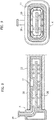
- FIG. 1 illustrates another embodiment of a structural node included in a lattice frame according to the present invention, in which at least one arm 4 can be connected by means of an adhesive material to a respective beam element 11, in such a way that the walls of the arm 4 are arranged within a respective end portion of the beam element 11.
- This arm 4 may include one or more inlet ports 19 for injecting the adhesive material, an axial supply channel 20 for the adhesive material, extending inside the arm 4 and a plurality of outlet ports 21 for the adhesive material ( Figures 5 , 7-9 , 12 ).
- the inlet ports 19 can be arranged near the central body of the node and can be made in the form of a pin, protruding from the walls that define the arm 4. As illustrated in the example of Figure 7 , there can be two inlet ports 19, protruding from two opposite sides of the arm 4.
- the supply channel 20 has an inlet end, coinciding with the inlet port 19, and an overall extension corresponding to the length of the arm 4.
- the channel 20 encloses an inner portion 26 of the arm 4, thus extending between the outer walls of the arm 4 and this inner portion 26.
- the outlet ports 21 for the adhesive material can be constituted by holes formed through the walls of the arm 4, distributed along its extension and extending radially between the axial supply channel 20 of the adhesive material and the outer walls of the arm 4. Thanks to this characteristic, gluing of the arm 4 within the respective beam element 11 is made extremely effective and long-lasting, since a homogeneous distribution of the adhesive material is obtained along the entire extension of the arm 4.
- the arm 4 of one of the nodes is connected to the respective hollow beam element 11, not only with the aid of an adhesive material, but also by means of a preliminary mechanical coupling.
- the preliminary mechanical coupling is achieved by connecting members, which can include an elastic arm 17 arranged on one side of the arm 4 and an opening 18 formed on one side of the beam element, in such a way that, in an assembled condition, the elastic arm 17 is coupled with the opening 18, thus creating a mechanical engagement between the arm 4 and the beam element 11.
- At least one of the aforesaid arms 4 provided with the supply channel 20 and the holes constituting the outlet ports 21 is formed by a pair of arms 4 arranged side-by-side and configured to be mounted within a single beam element 11 ( Figures 5 , 12 ).
- At least one of the structural nodes N2 of the lattice frame T according to the invention comprises a plurality of the aforesaid arms 4 provided with the supply channel 20 and the holes constituting the outlet ports 21 ( Figure 10 ).
- the node N2 may comprise a single inlet port 19 for the adhesive material, communicating with a central chamber 23, located within the central body 1 of the node N2, from which the supply channels 20 of the respective arms 4 extend.
- the number of arms and their configuration can widely vary with respect to what is shown in Figures 10 and 11 .
- an arm 2 with a C-channel shape can be added, protruding from the same central body 1 from which the three arms 4 also protrude.
- Figures 13A-13E illustrate some components constituting a further embodiment of a lattice frame according to the present invention, in which one arm 30 of a node is arranged within a beam element 27.
- the arm 30 is provided with a plurality of spacer elements 22 arranged along its extension, configured to define, in the assembled condition, a free space between the inner surface of the beam element 27 and the outer surface of the arm 30.
- the beam element 27 can be provided with one or more inlet ports (not shown in Figures 13A-13E ), in which the adhesive material can be introduced, to flow within the aforesaid free space and to glue between the beam element 27 and the arm 30.
- the spacer elements 22 are conical in shape to allow passage of the adhesive layer into the free space, along the entire extension of the hollow arm 27.
- the beam element 27 can have an opening 28 formed on one of its sides, configured to receive an elastic arm 29 arranged on one side of the arm 30, so as to provide a mechanical coupling between the arm 30 and the beam element 27.
- the motor-vehicle lattice frame according to the invention has a rapid and low-cost production and assembly process, without thereby being less effective in performing the functions for which it is designed.
- Producing the nodes by means of an additive manufacturing constructive technique means it is possible to obtain numerous advantages with respect to traditional production methods, among which, preparing components with complex geometries without incurring penalties in terms of time or cost with respect to the production of components with more simple geometries.
Description
- The present invention relates in general to motor-vehicle frames and more specifically to a motor-vehicle lattice frame comprising:
- a plurality of structural nodes each having a central body and at least one hollow arm protruding from the central body, and
- a plurality of beam elements connected to each other by means of the protruding arms.
- The document
US 4355844 A illustrates a motor-vehicle frame having the characteristics indicated above. In addition,WO 2016/003982 A1 discloses a motor vehicle lattice frame structure according to the preamble ofclaim 1 comprising a plurality of structural nodes, each having a central body and at least one hollow arm protruding from the central body, and a plurality of beam elements connected to each other by means of the hollow protruding arms, said structural nodes being made using an additive manufacturing technique. - The present invention is based on the requirement to provide a motor-vehicle lattice frame which has a rapid and low-cost production and assembly method, without thereby being less effective in performing the functions for which it is designed.
- An additional object of the invention is to provide a motor-vehicle lattice frame consisting of components suitable for producing different frame geometries.
- In order to achieve one or more of the aforesaid objects, the invention relates to a motor-vehicle lattice frame of the type indicated at the beginning of the present description and also characterized in that at least one arm of one of the nodes has an end portion opposite to the central body having a channel conformation with an open cavity both at a front end of the arm and along one side of the arm.
- Preferably, said end portion having a channel-shaped configuration includes two side flanges each extending along one side of the arm, at a respective side of said open cavity, so that said at least one arm has an Ω cross-section at said end portion.
- The beam element connected to said at least one arm with an Ω cross-section can include two end flanges arranged in abutment against said side flanges, so as to define a free space between the inner surface of the hollow arm and the beam element inserted into said channel-shaped end portion.
- According to a further preferred characteristic, said beam element is connected to said at least one arm with a channel-shaped end portion, only by the aid of an adhesive layer.
- Further characteristics and advantages of the invention will become apparent from the description that follows with reference to the attached drawings, provided purely by way of non-limiting example, wherein:
-
Figure 1 is a schematic view of a motor-vehicle lattice frame according to the present invention, -
Figure 2 is a perspective view illustrating some components of a motor-vehicle lattice frame according to a first embodiment, -
Figures 3-5 are perspective views showing some details illustrated inFigure 2 , -
Figure 6 is a schematic cross-sectional view of some components of the frame according to a variant with respect to what is shown in the previous figures, -
Figure 7 illustrates an exploded perspective view of some components of the frame according to a further variant with respect to that shown in the previous figures, -
Figures 8-9 are cross-sectional views of the details shown inFigure 7 , in an assembled condition, -
Figures 10 and11 illustrate, respectively, a perspective view and a cross-sectioned perspective view of a part of a motor-vehicle lattice frame according to the invention, -
Figure 12 illustrates a perspective view of a portion of a motor-vehicle lattice frame according to the invention, and -
Figures 13A-13E illustrate assembly steps of some details of a motor- vehicle lattice frame according to the invention. - In the following description various specific details are illustrated aimed at a thorough understanding of the embodiments. The embodiments can be implemented without one or more of the specific details, or with other methods, components, materials, etc. In other cases, known structures, materials, or operations are not shown or described in detail to avoid obscuring various aspects of the embodiments. The reference to "an embodiment" in the context of this description indicates that a particular configuration, structure or characteristic described in relation to the embodiment is included in at least one embodiment. Therefore, phrases such as "in an embodiment", possibly present in different places of this description do not necessarily refer to the same embodiment. Moreover, particular conformations, structures or characteristics can be combined in a suitable manner in one or more embodiments and/or associated with the embodiments in a different way from that illustrated here, for example, a characteristic here exemplified in relation to a figure may be applied to one or more embodiments exemplified in a different figure.
- The references illustrated here are only for convenience and do not therefore delimit the field of protection or the scope of the embodiments.
- In the present description and in the claims that follow, the term "additive manufacturing" means a method, known in the art, in which an energy source is used, such as a laser or plasma beam, to selectively melt layers of metal or plastic powders or wires, of various sizes, so as to form - layer after layer - a metal or plastic component.
- For example, a device for making components using additive manufacturing is known from the document
EP 3148784 A1 . Of course, the technology illustrated in this document is just an example, since different additive manufacturing technologies can be applied to make the motor-vehicle lattice frame according to the present invention. - The attached drawings show preferred embodiments of a motor-vehicle lattice frame T according to the present invention. The present invention may relate to any type of motor-vehicle frame, for example, a frame of a motor-vehicle structure, or a frame for supporting a component installed on the motor-vehicle.
- As shown in particular in the schematic view of
Figure 1 , the motor-vehicle lattice frame T comprises a plurality of structural nodes N1, N2 each having acentral body 1 from which at least twohollow arms beam elements arms - In the following description, various embodiments of the structural nodes N1, N2 will be described in detail to provide a lattice frame T of a motor-vehicle according to the present invention.
- According to an essential characteristic of the present invention, the structural nodes N1, N2 of the lattice frame T are obtained with a construction technique of "additive manufacturing". By producing the structural nodes by means of an additive manufacturing technique it is possible to obtain numerous advantages with respect to the traditional production methods, among which, preparing components with complex geometries without incurring penalties in terms of time or cost with respect to the production of components with more simple geometries. In the case of the invention, the structural nodes can be made of metal or plastic material, while the beam elements connected to each other by means of the structural nodes, can be made, for example, of aluminium alloy.
-
Figure 2 shows a perspective view of a first embodiment of a motor-vehicle structural node N1. As indicated above, each structural node, which together with the beam elements composes the lattice frame T, includes acentral body 1 and a plurality ofhollow arms central body 1. The hollow arms can be arranged around the central body according to multiple configurations so as to achieve the required geometry of the frame. - According to an important characteristic of the frame T according to the invention, at least one
arm 2 of one of the nodes has an end portion opposite thecentral body 1 which includes a C-channel shape with an open cavity both at afront end 12 of thearm 2 and along aside 13 of the arm 2 (Figures 2-4 ). - The C-channel conformation with an open cavity is arranged to receive a
respective beam element 6 therein, intended to be connected at one of its opposite ends to another structural node. - The
beam element 6 is connected to thearm 2 only by the aid of an adhesive layer. Still with reference toFigures 2-4 , in order to produce the bonding between thearm 2 and thebeam element 6, the C-channel shaped end portion includes twoopposite side walls 14 on which at least oneopening 7 is made to allow the passage of the adhesive layer. Of course, the configuration of theopenings 7 for introducing the adhesive material can widely vary with respect to what is illustrated in the attached drawings, without thereby departing from the scope of the present invention. - Thanks to the characteristic of providing at least one arm of a structural node with an end portion having the aforesaid C-channel conformation, it is possible to produce various geometries of the frame, including frames with two beam elements constrained to each other by an angle of 45° and intended to be connected together with a single structural node at the ends defining the aforesaid angle.
- According to a preferred characteristic of the invention, illustrated in the cross-sectional view of
Figure 6 , the aforesaid C-channel shaped end portion includes twoside flanges 10 each spaced along one side of thearm 2 at a respective side of the open cavity of the C-channel conformation, in such a way that the arm protruding from thecentral body 1 has an Ω-like cross-section at the aforesaid end portion. - Still referring to the cross-sectioned view of
Figure 6 , thebeam element 6, connected to the arm with an Ω-cross-section, also includes twoend flanges 33 arranged in abutment against theside flanges 10 of the arm protruding from thecentral body 1 of the node, so as to define a free space between the inner surface of the hollow arm and the beam element inserted within the end portion with a C-channel conformation. It will therefore be appreciated that, in one embodiment, the adhesive layer inserted within theopenings 7 spreads within the aforesaid free space formed between the inner surface of the hollow arm and the beam element inserted within the end portion with a C-channel conformation. - According to another preferred characteristic of the invention, illustrated in the perspective view of
Figure 5 , thearm 2 including the C-channel conformation may include a rigid coveringelement 8 connected to the end portion of thearm 2 with a C-channel conformation. The rigid coveringelement 8 is spaced along at least one side of the arm above the aforesaid open cavity and above the beam element arranged within the cavity. Preferably, the coveringelement 8 is slidably mounted onrespective guides 24, after the positioning of one end of thebeam element 6 within the aforesaid cavity has occurred. The coveringelement 8 is configured to slide on the guides (for example, conical) and remain blocked with interference fit on theguides 24 and on thebeam element 6. In this way, thebeam element 6 is locked in position until the adhesive material is injected. - In the following description, various additional embodiments of the structural nodes will be described, to provide a lattice frame T of a motor-vehicle according to the present invention.
- As illustrated in particular in
Figures 2-4 , onearm 3 of one of the nodes may have anend portion 14 arranged within the cavity of thehollow arm 3 and protruding in the opposite direction with respect to thecentral body 1 of the structural node. Theend portion 14 is configured to be mounted with a respectivehollow beam element 5, so that one end of thebeam element 5, coupled with the structural node, is interposed between the walls of thehollow arm 3, and theend portion 14 protruding in a direction opposite to thecentral body 1. - The
hollow beam element 5 may defineseveral cavities 15 arranged side-by-side and separated from each other by at least oneintermediate wall 16. In this case, theaforesaid end portion 14 arranged within the cavity of thehollow arm 3 defines respective protruding sectors divided by afree space 25, arranged to receive theintermediate wall 16 of thebeam element 6 mounted with interference fit with thearm 3 of the structural node. - The attached drawings illustrate another embodiment of a structural node included in a lattice frame according to the present invention, in which at least one
arm 4 can be connected by means of an adhesive material to arespective beam element 11, in such a way that the walls of thearm 4 are arranged within a respective end portion of thebeam element 11. Thisarm 4 may include one ormore inlet ports 19 for injecting the adhesive material, anaxial supply channel 20 for the adhesive material, extending inside thearm 4 and a plurality ofoutlet ports 21 for the adhesive material (Figures 5 ,7-9 ,12 ). - The
inlet ports 19 can be arranged near the central body of the node and can be made in the form of a pin, protruding from the walls that define thearm 4. As illustrated in the example ofFigure 7 , there can be twoinlet ports 19, protruding from two opposite sides of thearm 4. - As illustrated in
Figures 8, 9 , thesupply channel 20 has an inlet end, coinciding with theinlet port 19, and an overall extension corresponding to the length of thearm 4. In the case illustrated inFigures 8, 9 , inside thearm 4, thechannel 20 encloses aninner portion 26 of thearm 4, thus extending between the outer walls of thearm 4 and thisinner portion 26. - The
outlet ports 21 for the adhesive material can be constituted by holes formed through the walls of thearm 4, distributed along its extension and extending radially between theaxial supply channel 20 of the adhesive material and the outer walls of thearm 4. Thanks to this characteristic, gluing of thearm 4 within therespective beam element 11 is made extremely effective and long-lasting, since a homogeneous distribution of the adhesive material is obtained along the entire extension of thearm 4. - According to another preferred characteristic illustrated in the drawings, the
arm 4 of one of the nodes is connected to the respectivehollow beam element 11, not only with the aid of an adhesive material, but also by means of a preliminary mechanical coupling. The preliminary mechanical coupling is achieved by connecting members, which can include anelastic arm 17 arranged on one side of thearm 4 and an opening 18 formed on one side of the beam element, in such a way that, in an assembled condition, theelastic arm 17 is coupled with the opening 18, thus creating a mechanical engagement between thearm 4 and thebeam element 11. - Preferably, at least one of the
aforesaid arms 4 provided with thesupply channel 20 and the holes constituting theoutlet ports 21 is formed by a pair ofarms 4 arranged side-by-side and configured to be mounted within a single beam element 11 (Figures 5 ,12 ). - Preferably, at least one of the structural nodes N2 of the lattice frame T according to the invention comprises a plurality of the
aforesaid arms 4 provided with thesupply channel 20 and the holes constituting the outlet ports 21 (Figure 10 ). In this case, the node N2 may comprise asingle inlet port 19 for the adhesive material, communicating with acentral chamber 23, located within thecentral body 1 of the node N2, from which thesupply channels 20 of therespective arms 4 extend. Of course, the number of arms and their configuration can widely vary with respect to what is shown inFigures 10 and11 . For example, as well as the threearms 4 with ansupply channel 20 illustrated inFigures 10 and11 , anarm 2 with a C-channel shape can be added, protruding from the samecentral body 1 from which the threearms 4 also protrude. -
Figures 13A-13E illustrate some components constituting a further embodiment of a lattice frame according to the present invention, in which onearm 30 of a node is arranged within abeam element 27. Thearm 30 is provided with a plurality ofspacer elements 22 arranged along its extension, configured to define, in the assembled condition, a free space between the inner surface of thebeam element 27 and the outer surface of thearm 30. Thebeam element 27 can be provided with one or more inlet ports (not shown inFigures 13A-13E ), in which the adhesive material can be introduced, to flow within the aforesaid free space and to glue between thebeam element 27 and thearm 30. Preferably thespacer elements 22 are conical in shape to allow passage of the adhesive layer into the free space, along the entire extension of thehollow arm 27. - Similar to that described above, the
beam element 27 can have anopening 28 formed on one of its sides, configured to receive anelastic arm 29 arranged on one side of thearm 30, so as to provide a mechanical coupling between thearm 30 and thebeam element 27. - It should therefore be observed that the motor-vehicle lattice frame according to the invention has a rapid and low-cost production and assembly process, without thereby being less effective in performing the functions for which it is designed.
- Producing the nodes by means of an additive manufacturing constructive technique means it is possible to obtain numerous advantages with respect to traditional production methods, among which, preparing components with complex geometries without incurring penalties in terms of time or cost with respect to the production of components with more simple geometries.
- Thanks to the characteristic of providing at least one arm of a structural node with an end portion having the aforesaid C-channel conformation, it is possible to produce various frame geometries, including frames with two beam elements constrained to each other by an angle of 45° and intended to be connected together with a single structural node at their ends defining the aforesaid angle.
- Thanks to the characteristic of providing at least one arm of a structural node with outlet ports composed of holes formed through the walls of the arm, distributed along its extension and extending radially between the axial channel for supplying the adhesive material and the outer walls of the arm, gluing of the arm within the respective hollow beam element is made extremely effective and long-lasting, since a homogeneous distribution of the adhesive material along the entire length of the arm is ensured.
- Of course, without prejudice to the principle of the invention, the details of construction and the embodiments may vary widely with respect to those described and illustrated purely by way of example, without departing from the scope of the present invention as defined by the appended claims.
Claims (13)
- A motor-vehicle lattice frame (T) comprising:- a plurality of structural nodes (N1, N2) each having a central body (1) and at least one hollow arm (2, 3, 4, 30) protruding from the central body (1), and- a plurality of beam elements (5, 6, 11, 27) connected to each other by means of the hollow protruding arms (2, 3, 4, 30), wherein- said structural nodes (N1, N2) are made by an additive manufacturing technique, characterized in that at least one arm (2, 3, 4, 30) of one of the nodes (N1, N2) has an end portion opposite to said central body (1) having a channel shape (C) with an open cavity both at a front end (12) of the arm (2, 3, 4, 30) and along one side (13) of the arm (2, 3, 4, 30).
- A motor-vehicle lattice frame (T) according to claim 1, characterized in that said end portion having a channel-shaped conformation (C) includes two side flanges (10) each extending along one side of the arm (2, 3, 4, 30), at a respective side of said open cavity (C), in such a way that said at least one arm (2, 3, 4, 30) has an Ω cross- section at said end portion.
- A motor-vehicle lattice frame (T) according to claim 2, characterized in that at least one beam element (5, 6, 11, 27) connected to said at least one arm (2, 3, 4, 30) with an Ω cross-section, includes two end flanges (33) arranged in abutment against said side flanges (10), so as to define a free space between the inner surface of the hollow arm (2, 3, 4, 30) and the beam element (5, 6, 11, 27) inserted into said channel-shaped end portion (C).
- A motor-vehicle lattice frame (T) according to claim 3, characterized in that said beam element (5, 6, 11, 27) is connected to said at least one arm (2, 3, 4, 30) with a channel-shaped end portion (C), only by means of the aid of an adhesive layer.
- A motor-vehicle lattice frame (T) according to claim 4, characterized in that said channel-shaped end portion (C) includes two opposite side walls (14) on which at least one opening (7) is formed for the passage of the adhesive layer.
- A motor-vehicle lattice frame (T) according to claim 5, characterized in that said adhesive layer is diffused within said free space between the inner surface of the hollow arm (2, 3, 4, 30) and the beam element (5, 6, 11, 27) inserted within said channel-shaped end portion (C).
- A motor-vehicle lattice frame (T) according to any one of the preceding claims, characterized in that said at least one arm (2, 3, 4, 30) includes a rigid covering element (8) slidably mounted on said channel-shaped end portion (C) and arranged along at least one side of the arm (2, 3, 4, 30) above said open cavity and above the beam element (5, 6, 11, 27) arranged within the cavity, to lock the beam element (5, 6, 11, 27).
- A motor-vehicle lattice frame (T) according to claim 1, characterized in that at least one arm (2, 3, 4, 30) of one of the structural nodes (N1, N2) is connected to a respective hollow beam element (5, 6, 11, 27) by means of a preliminary mechanical coupling and by means of an adhesive material, said at least one arm (2, 3, 4, 30) being arranged within a respective hollow beam element (5, 6, 11, 27).
- A motor-vehicle lattice frame (T) according to claim 8, characterized in that said preliminary mechanical coupling is carried out by means of connecting members including an elastic arm (17) arranged on the side of said at least one arm (2, 3, 4, 30) and an opening (18) obtained on one side of the beam element (5, 6, 11, 27), so that, in an assembled condition, said at least one arm (2, 3, 4, 30) has a wall engaged adjacent to the wall of the beam element (5, 6, 11, 27) provided with said opening (18).
- A motor-vehicle lattice frame (T) according to claim 8 or 9, characterized in that said at least one arm (2, 3, 4, 30) includes at least one inlet port (19) for injecting the adhesive material, an axial channel (20) for supplying the adhesive material, extending inside the arm (2, 3, 4, 30), and a plurality of outlet ports (21) consisting of holes formed through the walls of the arm (2, 3, 4, 30), distributed along the entire extension of the arm and extending radially between the axial channel (20) for supplying the adhesive material and the outer surface of said at least one arm (2, 3, 4, 30).
- A motor-vehicle lattice frame (T) according to claims 9 or 10, characterized in that said at least one arm (2, 3, 4, 30) is formed by a pair of arms according to claim 12 arranged side-by-side and configured to be mounted within a single beam element (5, 6, 11, 27).
- A motor-vehicle lattice frame (T) according to claim 1, characterized in that at least one hollow arm (2, 3, 4, 30) is arranged within an end portion of a beam element (5, 6, 11, 27) and is provided with a plurality of spacer elements (22) arranged along its extension, configured to define, in the mounted condition, a free space between the inner surface of the hollow arm (2, 3, 4, 30) and the outer surface of the beam element (5, 6, 11, 27).
- A motor-vehicle including at least one lattice frame (T) according any one of the preceding claims
Priority Applications (6)
| Application Number | Priority Date | Filing Date | Title |
|---|---|---|---|
| EP19193174.0A EP3782879B1 (en) | 2019-08-22 | 2019-08-22 | Motor-vehicle lattice frame |
| CN202080040343.4A CN113874277A (en) | 2019-08-22 | 2020-07-08 | Automobile grille frame |
| US17/595,732 US11820433B2 (en) | 2019-08-22 | 2020-07-08 | Motor-vehicle lattice frame |
| KR1020227003431A KR20220048468A (en) | 2019-08-22 | 2020-07-08 | Motor-vehicle grid frame |
| PCT/IB2020/056409 WO2021033039A1 (en) | 2019-08-22 | 2020-07-08 | A motor-vehicle lattice frame |
| JP2021567840A JP2022545052A (en) | 2019-08-22 | 2020-07-08 | automotive lattice frame |
Applications Claiming Priority (1)
| Application Number | Priority Date | Filing Date | Title |
|---|---|---|---|
| EP19193174.0A EP3782879B1 (en) | 2019-08-22 | 2019-08-22 | Motor-vehicle lattice frame |
Publications (2)
| Publication Number | Publication Date |
|---|---|
| EP3782879A1 EP3782879A1 (en) | 2021-02-24 |
| EP3782879B1 true EP3782879B1 (en) | 2021-12-15 |
Family
ID=68109082
Family Applications (1)
| Application Number | Title | Priority Date | Filing Date |
|---|---|---|---|
| EP19193174.0A Active EP3782879B1 (en) | 2019-08-22 | 2019-08-22 | Motor-vehicle lattice frame |
Country Status (6)
| Country | Link |
|---|---|
| US (1) | US11820433B2 (en) |
| EP (1) | EP3782879B1 (en) |
| JP (1) | JP2022545052A (en) |
| KR (1) | KR20220048468A (en) |
| CN (1) | CN113874277A (en) |
| WO (1) | WO2021033039A1 (en) |
Families Citing this family (4)
| Publication number | Priority date | Publication date | Assignee | Title |
|---|---|---|---|---|
| US10940609B2 (en) * | 2017-07-25 | 2021-03-09 | Divergent Technologies, Inc. | Methods and apparatus for additively manufactured endoskeleton-based transport structures |
| US20190391563A1 (en) * | 2018-06-22 | 2019-12-26 | Divergent Technologies, Inc. | Additive manufacturing-enabled platform for modular construction of vehicles using definition nodes |
| KR20210123876A (en) * | 2020-04-06 | 2021-10-14 | 현대자동차주식회사 | Body reinforcing apparatus for vehicle |
| EP4032755A1 (en) * | 2021-01-26 | 2022-07-27 | Volvo Construction Equipment AB | Support structure for a vehicle and method for assembling parts of a support structure for a vehicle |
Citations (1)
| Publication number | Priority date | Publication date | Assignee | Title |
|---|---|---|---|---|
| EP2236395B1 (en) * | 2009-03-31 | 2013-01-09 | Mazda Motor Corporation | Connection structure of tube-shaped frames, corresponding method and vehicle body |
Family Cites Families (20)
| Publication number | Priority date | Publication date | Assignee | Title |
|---|---|---|---|---|
| US4252364A (en) * | 1977-07-05 | 1981-02-24 | Mitsubishi Jidosha Kogyo Kabushiki Kaisha | Outer panel construction for a vehicle or the like |
| IT1165208B (en) | 1979-05-25 | 1987-04-22 | Fiat Auto Spa | SUPPORTING FRAME FOR MOTOR VEHICLES |
| US5332281A (en) * | 1992-04-30 | 1994-07-26 | Ford Motor Company | Space frame construction |
| US5343666A (en) * | 1992-10-28 | 1994-09-06 | Ford Motor Company | Space frame joint construction |
| US5848853A (en) * | 1997-01-08 | 1998-12-15 | Asha Corporation | Vehicle body space frame |
| ZA983068B (en) * | 1997-04-11 | 1998-10-13 | Joalto Design Inc | Vehicle chassis and body construction |
| US6621037B2 (en) * | 1997-10-16 | 2003-09-16 | Magna International Inc. | Welding material with conductive sheet and method |
| US6123378A (en) * | 1998-05-04 | 2000-09-26 | Aluminum Company Of America | Cross beam-main beam integral joint |
| DE60208401T2 (en) * | 2001-10-02 | 2006-09-07 | Magna International Inc., Aurora | GRID TUBE FRAME FOR TRUCK CABIN |
| US7325866B2 (en) * | 2001-11-09 | 2008-02-05 | Magna International Inc. | Modular underbody for a motor vehicle |
| US8528291B2 (en) * | 2009-02-03 | 2013-09-10 | Allred & Associates Inc. | 3-dimensional universal tube connector system |
| DE102009029657A1 (en) * | 2009-09-22 | 2011-03-24 | Deere & Company, Moline | Node element for a vehicle frame structure |
| US8833832B2 (en) * | 2011-08-16 | 2014-09-16 | Ford Global Technologies, Llc | Node for connecting vehicle body portions |
| DE102012112313A1 (en) * | 2012-12-14 | 2014-06-18 | Dr. Ing. H.C. F. Porsche Aktiengesellschaft | Motor vehicle portion in space frame construction, has profiles that are made of fiber-reinforced plastic, and connected together at node portion made of light metal |
| CN106794517B (en) | 2014-05-30 | 2020-06-23 | 普瑞玛工业股份有限公司 | Laser-operated machine for additive manufacturing by laser sintering and corresponding method |
| AU2015284265A1 (en) * | 2014-07-02 | 2017-02-16 | Divergent Technologies, Inc. | Systems and methods for fabricating joint members |
| DE102015100219B4 (en) * | 2015-01-09 | 2018-08-23 | Audi Ag | Component assembly for a bodyshell of a motor vehicle |
| US10173255B2 (en) * | 2016-06-09 | 2019-01-08 | Divergent Technologies, Inc. | Systems and methods for arc and node design and manufacture |
| US10605285B2 (en) * | 2017-08-08 | 2020-03-31 | Divergent Technologies, Inc. | Systems and methods for joining node and tube structures |
| DE202017105474U1 (en) * | 2017-09-08 | 2018-12-14 | Edag Engineering Gmbh | Material-optimized connection node |
-
2019
- 2019-08-22 EP EP19193174.0A patent/EP3782879B1/en active Active
-
2020
- 2020-07-08 JP JP2021567840A patent/JP2022545052A/en active Pending
- 2020-07-08 US US17/595,732 patent/US11820433B2/en active Active
- 2020-07-08 WO PCT/IB2020/056409 patent/WO2021033039A1/en active Application Filing
- 2020-07-08 CN CN202080040343.4A patent/CN113874277A/en active Pending
- 2020-07-08 KR KR1020227003431A patent/KR20220048468A/en unknown
Patent Citations (1)
| Publication number | Priority date | Publication date | Assignee | Title |
|---|---|---|---|---|
| EP2236395B1 (en) * | 2009-03-31 | 2013-01-09 | Mazda Motor Corporation | Connection structure of tube-shaped frames, corresponding method and vehicle body |
Also Published As
| Publication number | Publication date |
|---|---|
| EP3782879A1 (en) | 2021-02-24 |
| JP2022545052A (en) | 2022-10-25 |
| WO2021033039A1 (en) | 2021-02-25 |
| US20220250692A1 (en) | 2022-08-11 |
| KR20220048468A (en) | 2022-04-19 |
| CN113874277A (en) | 2021-12-31 |
| US11820433B2 (en) | 2023-11-21 |
Similar Documents
| Publication | Publication Date | Title |
|---|---|---|
| EP3782879B1 (en) | Motor-vehicle lattice frame | |
| EP3106382B1 (en) | Method for manufacturing a fuselage panel by overmoulding and fuselage panel thus obtained | |
| EP2974849B1 (en) | Composite structure of fiber-reinforced plastic sheet and metal sheet, and method for manufacturing same | |
| EP1682401B1 (en) | Structural element, use of a structural element and method for producing a structural element, particularly a cross member for a vehicle | |
| US10220578B2 (en) | Fiber composite material component, and method for producing a fiber composite material component | |
| RU2634853C2 (en) | Panels and fuselages of aircrafts from composite structures | |
| EP0962034A1 (en) | Microwave antennas | |
| DE102013201842A1 (en) | Radstern made of composite spoke elements and its connection to the rim base | |
| US10273015B2 (en) | Compartmentalized structure for the acoustic treatment and the de-icing of an aircraft nacelle and aircraft nacelle incorporating said structure | |
| WO2012062391A1 (en) | Structural motor vehicle component comprising semi-finished components connected by means of a node element, and production method | |
| US10384727B2 (en) | Method for producing a node structure with at least two profile components and node structure and vehicle body | |
| EP2472063A1 (en) | Vane made of a composite material | |
| KR19990044380A (en) | Manufacturing method and apparatus thereof for synthetic resin tubular body, and synthetic resin suction manifold | |
| CN208181181U (en) | Longitudinal beam and vehicle | |
| US20130030389A1 (en) | Method of insert molding a connection for catheter with varying diameters | |
| EP1725805A1 (en) | Molded article with metal reinforcing and method for its manufacture | |
| JP2006524158A (en) | Hollow composite cavity parts | |
| EP2825366B1 (en) | Composite structural element and method | |
| JP7173280B2 (en) | Composite structure and manufacturing method thereof | |
| CN209990871U (en) | Gear wheel | |
| EP2900444B1 (en) | Method of making a panel | |
| EP3091208B1 (en) | Fresh air supplying device for an internal combustion engine and corresponding manufacturing method | |
| US20070108646A1 (en) | Method of fabricating a composite structure with details | |
| KR102135718B1 (en) | Extruding mold for propellant grain of solid rocket motor and manufacturing method for propellant grain of solid rocket motor using the same | |
| EP3562656A1 (en) | Structural parts comprising an overmoulded insert |
Legal Events
| Date | Code | Title | Description |
|---|---|---|---|
| PUAI | Public reference made under article 153(3) epc to a published international application that has entered the european phase |
Free format text: ORIGINAL CODE: 0009012 |
|
| STAA | Information on the status of an ep patent application or granted ep patent |
Free format text: STATUS: REQUEST FOR EXAMINATION WAS MADE |
|
| 17P | Request for examination filed |
Effective date: 20200601 |
|
| AK | Designated contracting states |
Kind code of ref document: A1 Designated state(s): AL AT BE BG CH CY CZ DE DK EE ES FI FR GB GR HR HU IE IS IT LI LT LU LV MC MK MT NL NO PL PT RO RS SE SI SK SM TR |
|
| AX | Request for extension of the european patent |
Extension state: BA ME |
|
| GRAP | Despatch of communication of intention to grant a patent |
Free format text: ORIGINAL CODE: EPIDOSNIGR1 |
|
| STAA | Information on the status of an ep patent application or granted ep patent |
Free format text: STATUS: GRANT OF PATENT IS INTENDED |
|
| RIC1 | Information provided on ipc code assigned before grant |
Ipc: B62D 23/00 20060101AFI20210719BHEP Ipc: B62D 27/06 20060101ALI20210719BHEP Ipc: B62D 27/02 20060101ALI20210719BHEP Ipc: B33Y 80/00 20150101ALI20210719BHEP |
|
| INTG | Intention to grant announced |
Effective date: 20210803 |
|
| RIN1 | Information on inventor provided before grant (corrected) |
Inventor name: BASSAN, DANIELE Inventor name: SANDRI, SILVANO Inventor name: LONGO, MICHELE Inventor name: PARADISO, STEFANO Inventor name: CARCIOFFI, CARLO |
|
| GRAS | Grant fee paid |
Free format text: ORIGINAL CODE: EPIDOSNIGR3 |
|
| GRAA | (expected) grant |
Free format text: ORIGINAL CODE: 0009210 |
|
| STAA | Information on the status of an ep patent application or granted ep patent |
Free format text: STATUS: THE PATENT HAS BEEN GRANTED |
|
| AK | Designated contracting states |
Kind code of ref document: B1 Designated state(s): AL AT BE BG CH CY CZ DE DK EE ES FI FR GB GR HR HU IE IS IT LI LT LU LV MC MK MT NL NO PL PT RO RS SE SI SK SM TR |
|
| REG | Reference to a national code |
Ref country code: GB Ref legal event code: FG4D Ref country code: CH Ref legal event code: EP |
|
| REG | Reference to a national code |
Ref country code: IE Ref legal event code: FG4D Ref country code: DE Ref legal event code: R096 Ref document number: 602019010044 Country of ref document: DE |
|
| REG | Reference to a national code |
Ref country code: AT Ref legal event code: REF Ref document number: 1455299 Country of ref document: AT Kind code of ref document: T Effective date: 20220115 |
|
| REG | Reference to a national code |
Ref country code: LT Ref legal event code: MG9D |
|
| REG | Reference to a national code |
Ref country code: NL Ref legal event code: MP Effective date: 20211215 |
|
| PG25 | Lapsed in a contracting state [announced via postgrant information from national office to epo] |
Ref country code: RS Free format text: LAPSE BECAUSE OF FAILURE TO SUBMIT A TRANSLATION OF THE DESCRIPTION OR TO PAY THE FEE WITHIN THE PRESCRIBED TIME-LIMIT Effective date: 20211215 Ref country code: LT Free format text: LAPSE BECAUSE OF FAILURE TO SUBMIT A TRANSLATION OF THE DESCRIPTION OR TO PAY THE FEE WITHIN THE PRESCRIBED TIME-LIMIT Effective date: 20211215 Ref country code: FI Free format text: LAPSE BECAUSE OF FAILURE TO SUBMIT A TRANSLATION OF THE DESCRIPTION OR TO PAY THE FEE WITHIN THE PRESCRIBED TIME-LIMIT Effective date: 20211215 Ref country code: BG Free format text: LAPSE BECAUSE OF FAILURE TO SUBMIT A TRANSLATION OF THE DESCRIPTION OR TO PAY THE FEE WITHIN THE PRESCRIBED TIME-LIMIT Effective date: 20220315 |
|
| REG | Reference to a national code |
Ref country code: AT Ref legal event code: MK05 Ref document number: 1455299 Country of ref document: AT Kind code of ref document: T Effective date: 20211215 |
|
| PG25 | Lapsed in a contracting state [announced via postgrant information from national office to epo] |
Ref country code: SE Free format text: LAPSE BECAUSE OF FAILURE TO SUBMIT A TRANSLATION OF THE DESCRIPTION OR TO PAY THE FEE WITHIN THE PRESCRIBED TIME-LIMIT Effective date: 20211215 Ref country code: NO Free format text: LAPSE BECAUSE OF FAILURE TO SUBMIT A TRANSLATION OF THE DESCRIPTION OR TO PAY THE FEE WITHIN THE PRESCRIBED TIME-LIMIT Effective date: 20220315 Ref country code: LV Free format text: LAPSE BECAUSE OF FAILURE TO SUBMIT A TRANSLATION OF THE DESCRIPTION OR TO PAY THE FEE WITHIN THE PRESCRIBED TIME-LIMIT Effective date: 20211215 Ref country code: HR Free format text: LAPSE BECAUSE OF FAILURE TO SUBMIT A TRANSLATION OF THE DESCRIPTION OR TO PAY THE FEE WITHIN THE PRESCRIBED TIME-LIMIT Effective date: 20211215 Ref country code: GR Free format text: LAPSE BECAUSE OF FAILURE TO SUBMIT A TRANSLATION OF THE DESCRIPTION OR TO PAY THE FEE WITHIN THE PRESCRIBED TIME-LIMIT Effective date: 20220316 |
|
| PG25 | Lapsed in a contracting state [announced via postgrant information from national office to epo] |
Ref country code: NL Free format text: LAPSE BECAUSE OF FAILURE TO SUBMIT A TRANSLATION OF THE DESCRIPTION OR TO PAY THE FEE WITHIN THE PRESCRIBED TIME-LIMIT Effective date: 20211215 |
|
| PG25 | Lapsed in a contracting state [announced via postgrant information from national office to epo] |
Ref country code: SM Free format text: LAPSE BECAUSE OF FAILURE TO SUBMIT A TRANSLATION OF THE DESCRIPTION OR TO PAY THE FEE WITHIN THE PRESCRIBED TIME-LIMIT Effective date: 20211215 Ref country code: SK Free format text: LAPSE BECAUSE OF FAILURE TO SUBMIT A TRANSLATION OF THE DESCRIPTION OR TO PAY THE FEE WITHIN THE PRESCRIBED TIME-LIMIT Effective date: 20211215 Ref country code: RO Free format text: LAPSE BECAUSE OF FAILURE TO SUBMIT A TRANSLATION OF THE DESCRIPTION OR TO PAY THE FEE WITHIN THE PRESCRIBED TIME-LIMIT Effective date: 20211215 Ref country code: PT Free format text: LAPSE BECAUSE OF FAILURE TO SUBMIT A TRANSLATION OF THE DESCRIPTION OR TO PAY THE FEE WITHIN THE PRESCRIBED TIME-LIMIT Effective date: 20220418 Ref country code: ES Free format text: LAPSE BECAUSE OF FAILURE TO SUBMIT A TRANSLATION OF THE DESCRIPTION OR TO PAY THE FEE WITHIN THE PRESCRIBED TIME-LIMIT Effective date: 20211215 Ref country code: EE Free format text: LAPSE BECAUSE OF FAILURE TO SUBMIT A TRANSLATION OF THE DESCRIPTION OR TO PAY THE FEE WITHIN THE PRESCRIBED TIME-LIMIT Effective date: 20211215 Ref country code: CZ Free format text: LAPSE BECAUSE OF FAILURE TO SUBMIT A TRANSLATION OF THE DESCRIPTION OR TO PAY THE FEE WITHIN THE PRESCRIBED TIME-LIMIT Effective date: 20211215 |
|
| PG25 | Lapsed in a contracting state [announced via postgrant information from national office to epo] |
Ref country code: PL Free format text: LAPSE BECAUSE OF FAILURE TO SUBMIT A TRANSLATION OF THE DESCRIPTION OR TO PAY THE FEE WITHIN THE PRESCRIBED TIME-LIMIT Effective date: 20211215 Ref country code: AT Free format text: LAPSE BECAUSE OF FAILURE TO SUBMIT A TRANSLATION OF THE DESCRIPTION OR TO PAY THE FEE WITHIN THE PRESCRIBED TIME-LIMIT Effective date: 20211215 |
|
| REG | Reference to a national code |
Ref country code: DE Ref legal event code: R097 Ref document number: 602019010044 Country of ref document: DE |
|
| PG25 | Lapsed in a contracting state [announced via postgrant information from national office to epo] |
Ref country code: IS Free format text: LAPSE BECAUSE OF FAILURE TO SUBMIT A TRANSLATION OF THE DESCRIPTION OR TO PAY THE FEE WITHIN THE PRESCRIBED TIME-LIMIT Effective date: 20220415 |
|
| PLBE | No opposition filed within time limit |
Free format text: ORIGINAL CODE: 0009261 |
|
| STAA | Information on the status of an ep patent application or granted ep patent |
Free format text: STATUS: NO OPPOSITION FILED WITHIN TIME LIMIT |
|
| PG25 | Lapsed in a contracting state [announced via postgrant information from national office to epo] |
Ref country code: DK Free format text: LAPSE BECAUSE OF FAILURE TO SUBMIT A TRANSLATION OF THE DESCRIPTION OR TO PAY THE FEE WITHIN THE PRESCRIBED TIME-LIMIT Effective date: 20211215 Ref country code: AL Free format text: LAPSE BECAUSE OF FAILURE TO SUBMIT A TRANSLATION OF THE DESCRIPTION OR TO PAY THE FEE WITHIN THE PRESCRIBED TIME-LIMIT Effective date: 20211215 |
|
| 26N | No opposition filed |
Effective date: 20220916 |
|
| PG25 | Lapsed in a contracting state [announced via postgrant information from national office to epo] |
Ref country code: MC Free format text: LAPSE BECAUSE OF FAILURE TO SUBMIT A TRANSLATION OF THE DESCRIPTION OR TO PAY THE FEE WITHIN THE PRESCRIBED TIME-LIMIT Effective date: 20211215 |
|
| REG | Reference to a national code |
Ref country code: CH Ref legal event code: PL |
|
| PG25 | Lapsed in a contracting state [announced via postgrant information from national office to epo] |
Ref country code: LU Free format text: LAPSE BECAUSE OF NON-PAYMENT OF DUE FEES Effective date: 20220822 Ref country code: LI Free format text: LAPSE BECAUSE OF NON-PAYMENT OF DUE FEES Effective date: 20220831 Ref country code: CH Free format text: LAPSE BECAUSE OF NON-PAYMENT OF DUE FEES Effective date: 20220831 |
|
| REG | Reference to a national code |
Ref country code: BE Ref legal event code: MM Effective date: 20220831 |
|
| PG25 | Lapsed in a contracting state [announced via postgrant information from national office to epo] |
Ref country code: IE Free format text: LAPSE BECAUSE OF NON-PAYMENT OF DUE FEES Effective date: 20220822 |
|
| PG25 | Lapsed in a contracting state [announced via postgrant information from national office to epo] |
Ref country code: BE Free format text: LAPSE BECAUSE OF NON-PAYMENT OF DUE FEES Effective date: 20220831 |
|
| PGFP | Annual fee paid to national office [announced via postgrant information from national office to epo] |
Ref country code: IT Payment date: 20230720 Year of fee payment: 5 |
|
| PGFP | Annual fee paid to national office [announced via postgrant information from national office to epo] |
Ref country code: FR Payment date: 20230720 Year of fee payment: 5 Ref country code: DE Payment date: 20230720 Year of fee payment: 5 |
|
| GBPC | Gb: european patent ceased through non-payment of renewal fee |
Effective date: 20230822 |