EP3782718A1 - Hollow fiber membrane module and method for cleaning the same - Google Patents
Hollow fiber membrane module and method for cleaning the same Download PDFInfo
- Publication number
- EP3782718A1 EP3782718A1 EP19826911.0A EP19826911A EP3782718A1 EP 3782718 A1 EP3782718 A1 EP 3782718A1 EP 19826911 A EP19826911 A EP 19826911A EP 3782718 A1 EP3782718 A1 EP 3782718A1
- Authority
- EP
- European Patent Office
- Prior art keywords
- hollow fiber
- fiber membrane
- cleaning gas
- space
- cleaning
- Prior art date
- Legal status (The legal status is an assumption and is not a legal conclusion. Google has not performed a legal analysis and makes no representation as to the accuracy of the status listed.)
- Granted
Links
Images





Classifications
-
- B—PERFORMING OPERATIONS; TRANSPORTING
- B01—PHYSICAL OR CHEMICAL PROCESSES OR APPARATUS IN GENERAL
- B01D—SEPARATION
- B01D65/00—Accessories or auxiliary operations, in general, for separation processes or apparatus using semi-permeable membranes
- B01D65/02—Membrane cleaning or sterilisation ; Membrane regeneration
-
- B—PERFORMING OPERATIONS; TRANSPORTING
- B01—PHYSICAL OR CHEMICAL PROCESSES OR APPARATUS IN GENERAL
- B01D—SEPARATION
- B01D63/00—Apparatus in general for separation processes using semi-permeable membranes
- B01D63/02—Hollow fibre modules
-
- B—PERFORMING OPERATIONS; TRANSPORTING
- B01—PHYSICAL OR CHEMICAL PROCESSES OR APPARATUS IN GENERAL
- B01D—SEPARATION
- B01D63/00—Apparatus in general for separation processes using semi-permeable membranes
- B01D63/02—Hollow fibre modules
- B01D63/04—Hollow fibre modules comprising multiple hollow fibre assemblies
- B01D63/043—Hollow fibre modules comprising multiple hollow fibre assemblies with separate tube sheets
-
- B—PERFORMING OPERATIONS; TRANSPORTING
- B01—PHYSICAL OR CHEMICAL PROCESSES OR APPARATUS IN GENERAL
- B01D—SEPARATION
- B01D69/00—Semi-permeable membranes for separation processes or apparatus characterised by their form, structure or properties; Manufacturing processes specially adapted therefor
- B01D69/08—Hollow fibre membranes
-
- B—PERFORMING OPERATIONS; TRANSPORTING
- B01—PHYSICAL OR CHEMICAL PROCESSES OR APPARATUS IN GENERAL
- B01D—SEPARATION
- B01D71/00—Semi-permeable membranes for separation processes or apparatus characterised by the material; Manufacturing processes specially adapted therefor
- B01D71/06—Organic material
- B01D71/30—Polyalkenyl halides
- B01D71/32—Polyalkenyl halides containing fluorine atoms
- B01D71/34—Polyvinylidene fluoride
-
- B—PERFORMING OPERATIONS; TRANSPORTING
- B01—PHYSICAL OR CHEMICAL PROCESSES OR APPARATUS IN GENERAL
- B01D—SEPARATION
- B01D2313/00—Details relating to membrane modules or apparatus
- B01D2313/26—Specific gas distributors or gas intakes
-
- B—PERFORMING OPERATIONS; TRANSPORTING
- B01—PHYSICAL OR CHEMICAL PROCESSES OR APPARATUS IN GENERAL
- B01D—SEPARATION
- B01D2315/00—Details relating to the membrane module operation
- B01D2315/20—Operation control schemes defined by a periodically repeated sequence comprising filtration cycles combined with cleaning or gas supply, e.g. aeration
-
- B—PERFORMING OPERATIONS; TRANSPORTING
- B01—PHYSICAL OR CHEMICAL PROCESSES OR APPARATUS IN GENERAL
- B01D—SEPARATION
- B01D2321/00—Details relating to membrane cleaning, regeneration, sterilization or to the prevention of fouling
- B01D2321/04—Backflushing
-
- B—PERFORMING OPERATIONS; TRANSPORTING
- B01—PHYSICAL OR CHEMICAL PROCESSES OR APPARATUS IN GENERAL
- B01D—SEPARATION
- B01D2321/00—Details relating to membrane cleaning, regeneration, sterilization or to the prevention of fouling
- B01D2321/18—Use of gases
- B01D2321/185—Aeration
-
- Y—GENERAL TAGGING OF NEW TECHNOLOGICAL DEVELOPMENTS; GENERAL TAGGING OF CROSS-SECTIONAL TECHNOLOGIES SPANNING OVER SEVERAL SECTIONS OF THE IPC; TECHNICAL SUBJECTS COVERED BY FORMER USPC CROSS-REFERENCE ART COLLECTIONS [XRACs] AND DIGESTS
- Y02—TECHNOLOGIES OR APPLICATIONS FOR MITIGATION OR ADAPTATION AGAINST CLIMATE CHANGE
- Y02W—CLIMATE CHANGE MITIGATION TECHNOLOGIES RELATED TO WASTEWATER TREATMENT OR WASTE MANAGEMENT
- Y02W10/00—Technologies for wastewater treatment
- Y02W10/10—Biological treatment of water, waste water, or sewage
Definitions
- the present invention relates to a hollow fiber membrane module and a method for cleaning the same.
- hollow fiber membrane modules have been conventionally used in a filtration of removing impurities contained in water.
- a hollow fiber membrane module can obtain filtrated water after removing impurities from raw water (to be filtrated) having been supplied in a housing by causing the raw water to permeate hollow fiber membranes.
- Execution of the filtration by way of the hollow fiber membranes for a predetermined period of time causes an increase in an amount of deposition of suspended solids (SS) contained in the raw water onto membrane surfaces. This leads to a decline in filtration performance of the hollow fiber membranes. Accordingly, it is necessary to regularly clean the membrane surfaces.
- SS suspended solids
- Patent Literature 1 discloses a hollow fiber membrane module including a hollow fiber membrane bundle, a housing for accommodating the hollow fiber membrane bundle, a diffuser lying under the hollow fiber membrane bundle in the housing.
- the diffuser includes a disc-shaped main body and a cylindrical gas receiver provided on a bottom surface of the main body at the center thereof.
- the hollow fiber membrane module can temporarily store a cleaning gas having entered the housing in the receiver, effuse the stored cleaning gas radially outward, and thereafter diffuse the cleaning gas to the hollow fiber membrane bundle through diffusion holes. It is therefore possible to clean the surfaces of the hollow fiber membranes with the gas.
- the housing has a lower part formed with an inflow port for the cleaning gas.
- the inflow port may be formed in a peripheral part of a housing in accordance with a specification of a module.
- the cleaning gas enters the housing from an outer periphery of a diffuser. If adopting this structure, the diffuser in Patent Literature 1 would diffuse the cleaning gas through the diffusion holes before the cleaning gas flows thoroughly in the circumferential direction. This consequently makes it difficult to clean the hollow fiber membrane bundle uniformly in the circumferential direction with the gas.
- the location of the inflow port for the cleaning gas is restricted to the lower part of the housing in the conventional hollow fiber membrane module to clean the hollow fiber membrane bundle uniformly in the circumferential direction.
- Patent Literature 1 Japanese Unexamined Patent Publication No. 2016-87567
- An object of the present invention is to provide a hollow fiber membrane module and a method for cleaning the same, the module and the method achieving uniform cleaning of a hollow fiber membrane bundle in a circumferential direction with a cleaning gas even having entered from a peripheral part of a diffuser.
- a hollow fiber membrane module is a hollow fiber membrane module for an external pressure filtration, including: a hollow fiber membrane bundle including bundled hollow fiber membranes; a housing formed with a port for allowing a cleaning gas for cleaning the hollow fiber membrane bundle to inflow therethrough for accommodating the hollow fiber membrane bundle; and a diffuser having a receiving surface for receiving the cleaning gas having entered through the port, the receiving surface being formed with diffusion hole for diffusing the cleaning gas to the hollow fiber membrane bundle in the housing.
- the diffuser includes a partition dividing a space under the receiving surface into an inner space and an outer space surrounding the inner space and permitting the cleaning gas having entered through the port to flow thereinto.
- the diffusion hole is arranged to allow at least a part of the cleaning gas flowing in the outer space to diffuse from the inner space to the hollow fiber membrane bundle.
- a method for cleaning a hollow fiber membrane module includes a method for cleaning a hollow fiber membrane module for an external pressure filtration by cleaning a hollow fiber membrane bundle of the hollow fiber membrane module.
- the hollow fiber membrane module includes: a housing formed with a port for allowing a cleaning gas to inflow therethrough; the hollow fiber membrane bundle accommodated in the housing; and a diffuser having a receiving surface formed with diffusion hole for diffusing the cleaning gas to the hollow fiber membrane bundle in the housing, and defining an inner space and an outer space surrounding the inner space under the receiving surface.
- the method includes: flowing the cleaning gas into the outer space under the receiving surface of the diffuser through the port; flowing at least a part of the cleaning gas flowing in the outer space into the inner space; and diffusing the cleaning gas to the hollow fiber membrane bundle through the diffusion hole.
- the present invention it is possible to provide a hollow fiber membrane module and a method for cleaning the same, the module and the method achieving uniform cleaning of a hollow fiber membrane bundle in a circumferential direction with a cleaning gas even having entered from a peripheral part of a diffuser.
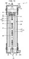
- the hollow fiber membrane module 1 is a module for an external pressure filtration, and mainly includes a hollow fiber membrane bundle 10 including bundled hollow fiber membranes 11, a housing 20, a diffuser 30, and a water flow pipe 40 as shown in Fig. 1 .
- the term "external pressure filtration” represents a filtration way of obtaining filtrated water from a space defined by inner surfaces of the hollow fiber membranes 11 by causing raw water to permeate the hollow fiber membranes 11 from the outer surfaces to the inner surfaces thereof through membrane walls. Elements of the hollow fiber membrane module 1 will be described below.
- the hollow fiber membrane bundle 10 includes a plurality of hollow fiber membranes 11 each of which vertically extends, and a retainer 12 which bind the plurality of hollow fiber membranes 11 together.
- the hollow fiber membrane bundle 10 has a one-free-end structure in which the hollow fiber membranes 11 have upper ends each retained by the retainer 12, and lower ends which are free without being retained.
- the lower end of each of the hollow fiber membranes 11 may be sealed with, for example, a resin, but the structure should not be particularly limited thereto.
- an outer peripheral surface of the retainer 12 is in close contact with the inner surface of the housing 20.
- hollow fiber membranes 11 Various materials may be adopted for the hollow fiber membranes 11. For instance, hydrophilized poly vinylidene difluoride (PVDF) is adoptable. Furthermore, an epoxy adhesive resin is, for example, adoptable for the retainer 12, but the material should not be limited thereto.
- PVDF hydrophilized poly vinylidene difluoride
- an epoxy adhesive resin is, for example, adoptable for the retainer 12, but the material should not be limited thereto.
- the housing 20 includes a hollow cylindrical container for accommodating the hollow fiber membrane bundle 10, and is disposed in a vertically standing posture as shown in Fig. 1 .
- the housing 20 has a housing main body 21, an upper cap 23, a lower cap 25, an upper coupling 27, and a lower coupling 28.
- Each of the housing main body 21, the upper cap 23, and the lower cap 25 is made of, for example, resin such as poly vinyl chloride (PVC).
- Each of the upper coupling 27 and the lower coupling 28 includes a ring-shaped fastener for fastening the upper cap 23 and the lower cap 25 to the housing main body 21.
- the housing main body 21 is a vertically extending hollow cylindrical member, and accommodates the hollow fiber membrane bundle 10.
- the housing main body 21 opens at an upper end and a lower end thereof, but the opening at the upper end is closed by the retainer 12.
- a space in the housing main body 21 is defined as a raw water space 21A to be filled with raw water (that is a target to be filtrated by the hollow fiber membranes 11).
- the upper cap 23 is attached to the upper end of the housing main body 21 by the upper coupling 27 to cover the opening at the upper end of the housing main body 21.
- a space in the upper cap 23 is defined as a filtrated water space 23B to be filled with filtrated water.
- the filtrated water space 23B communicates with the space defined by the inner surfaces of the hollow fiber membranes 11, but is liquid-tightly partitioned from the raw water space 21A across the retainer 12. Accordingly, it is possible to prevent the raw water and the filtrated water from mixing with each other.
- the upper cap 23 has a peripheral part formed with a filtrated water port 23A for taking out the filtrated water from the filtrated water space 23B to the outside therethrough.
- the lower cap 25 is attached to the lower end of the housing main body 21 by the lower coupling 28 to cover the opening at the lower end of the housing main body 21.
- the space in the lower cap 25 and the space in the housing main body 21 communicate with each other.
- the lower cap 25 has a peripheral part formed with a port 25A for draining to discharge the raw water from the housing 20 to the outside.
- the port 25A has a cylindrical shape extending radially outward from the peripheral surface of the lower cap 25, and an inner space communicating with the space in the lower cap 25.
- a draining pipe 22 is connected to the port 25A.
- the port 25A for draining serves as a port for allowing a cleaning gas (e.g., cleaning air) for cleaning the hollow fiber membrane bundle 10 to inflow therethrough.
- a cleaning gas e.g., cleaning air
- the draining pipe 22 is formed with an inlet 22A for the cleaning gas.
- a gas pipe 24A is connected to the inlet 22A.
- a pure cleaning gas generated in a gas generating source 24 such as an air compressor can enter the lower cap 25 through the port 25A after sequentially passing through the gas pipe 24A and the draining pipe 22.
- the diffuser 30 diffuses the cleaning gas having entered the housing 20 through the port 25A to the hollow fiber membrane bundle 10.
- the diffusion generates bubbles to rise from lower ends to upper ends of the hollow fiber membranes 11, resulting in achievement of cleaning the hollow fiber membranes 11.
- the diffuser 30 is made of, for example, resin such as the PVC like the housing 20, and lies under the hollow fiber membrane bundle 10. Details of the structure of the diffuser 30 will be described later.
- the water flow pipe 40 is a member for causing the raw water to enter the housing 20, and is arranged in the housing 20. As shown in Fig. 1 , the water flow pipe 40 penetrates through the bottom surface of the lower cap 25 at the center thereof and through the center of the diffuser 30, and vertically extends in an inside space defined by the hollow fiber membrane bundle 10.
- the water flow pipe 40 has, for example, a hollow cylindrical shape, and further has an upper end retained by the retainer 12 and a lower end formed with a raw water inflow port 44.
- the water flow pipe 40 also has a wall formed with a plurality of water passing holes 41 at intervals in the longitudinal and circumferential directions thereof.
- the raw water having flowed into the water flow pipe 40 through the raw water inflow port 44 advances upward from the lower end to the upper end of the water flow pipe 40 therein, and is supplied into the raw water space 21A through the water passing holes 41.
- a pipe partition plate 42 vertically dividing a pipe inner space is provided near the upper end of the water flow pipe 40. All the water passing holes 41 are formed in the pipe wall below the pipe partition plate 42.
- the pipe partition plate 42 can block the raw water there, and hence keep the raw water in the water flow pipe 40 from outflowing beyond the upper end thereof.
- the wall of the water flow pipe 40 is further formed with air venting holes 43 above the pipe partition plate 42 and below the retainer 12 in the water flow pipe 40.
- the upper end of the water flow pipe 40 is connected with an air venting pipe 26 communicating with the water flow pipe 40.
- the air venting pipe 26 penetrates through a top surface of the upper cap 23 at the center thereof. This configuration makes it possible to vent the air having flowed from the raw water space 21A into a space (above the pipe partition plate 42) in the water flow pipe 40 through the air venting holes 43 to the outside of the module through the air venting pipe 26.
- Fig. 2 is a plan view of the diffuser 30 (a view of the diffuser 30 seen from the top thereof).
- Fig. 3 is a bottom view of the diffuser 30 (a view of the diffuser 30 seen from the bottom thereof).
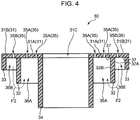
- Fig. 4 is a cross-sectional view of the diffuser 30 taken along the line IV-IV in Fig. 2 .
- the diffuser 30 has a receiving surface 37 for receiving the cleaning gas having entered through the port 25A, the receiving surface 37 being formed with diffusion holes 35 for diffusing the cleaning gas to the hollow fiber membrane bundle 10 in the housing 20.
- the diffuser 30 includes a disc-shaped main body 31 having the receiving surface 37 formed with a plurality of diffusion holes 35, and a partition 32 dividing a space under the receiving surface 37 into an inner space 36A and an outer space 36B.
- the main body 31 is a disc-shaped member made of resin and having a through hole 31C at the center thereof, and expands in radial directions of the hollow fiber membrane bundle 10.
- the main body 31 lies in a horizontal posture perpendicular to the longitudinal direction of the hollow fiber membranes 11 below the lower ends of the hollow fiber membranes 11.
- the through hole 31C receives the water flow pipe 40 inserted therein, and thus has a diameter larger than an outer diameter of the water flow pipe 40.
- the main body 31 should not be limited to the disc shape, and can have various shapes.
- Each of the diffusion holes 35 is a circular hole having a diameter smaller than that of the through hole 31C, and extends through the main body 31 in the thickness direction thereof. As shown in Fig. 2 , the diffusion holes 35 are at intervals in the radial and circumferential directions in a radially outward area of the through hole 31C. Specifically, defined are a first imaginary circle C1 which is concentric with the main body 31 and has a diameter larger than that of the through hole 31C, a second imaginary circle C2 which is concentric with the main body 31 and has a diameter larger than that of the first imaginary circle C1, and a third imaginary circle C3 which is concentric with the main body 31 and has a diameter larger than that of the second imaginary circle C2. Under this definition, the diffusion holes 35 are arranged at constant intervals on the circumferential outline of each of the first to third imaginary circles C1 to C3.
- diffusion holes 35 in a radially inward portion (an inner portion 31A) of the partition 32 is more densely arranged than diffusion holes 35 in a radially outward portion (an outer portion 31B) of the partition 32.
- each of the diffusion holes 35 in the inner portion 31A is also referred to as “inner diffusion hole 35A” and each of the diffusion holes 35 in the outer portion 31B is also referred to as “outer diffusion hole 35B".
- all the diffusion holes 35 have the same size and the same shape, but may have different sizes and shapes from one another without limitation thereto.
- the receiving surface 37 is the lower surface of the main body 31.
- the receiving surface 37 is the surface of the main body 31 which faces the lower part of the housing 20 that is opposite to the hollow fiber membrane bundle 10. That is to say, the receiving surface 37 vertically faces an inner bottom surface of the housing 20.
- the receiving surface 37 extends in a horizontal direction perpendicular to the longitudinal direction of the hollow fiber membranes 11. The cleaning gas having entered the housing 20 through the port 25A is received on the receiving surface 37, and thereafter diffuses to the hollow fiber membrane bundle 10 through the diffusion holes 35.
- the partition 32 has a cylindrical shape with a diameter larger than that of the through hole 31C, and has an upper end connected to the receiving surface 37 so as to be concentric with the main body 31.
- the space on the radially inside of the partition 32 is defined as the inner space 36A and the space on the radially outside of the partition 32 is defined as the outer space 36B under the receiving surface 37.
- the inner space 36A locates under the inner portion 31A of the main body 31
- the outer space 36B locates under the outer portion 31B of the main body 31.
- the inner space 36A and the outer space 36B can store the cleaning gas to diffuse through the diffusion holes 35.
- the inner space 36A is an annular space surrounding the through hole 31C in a plan view
- the outer space 36B is another annular space surrounding the inner space 36A in the plan view.
- the partition 32 has an outer peripheral surface 32A facing the outer space 36B and vertically extending, and an inner peripheral surface 32B facing the inner space 36A and vertically extending.
- the partition 32 in the embodiment has a cylindrical shape with a predetermined inner diameter from the upper end to the lower end thereof, but should not be limited to this shape.
- the partition 32 may have a shape with a diameter gradually increasing or decreasing from the upper end to the lower end.
- the partition 32 should not be limited to the cylindrical shape, and may have any other shape, e.g., a prism shape.
- the diffuser 30 further includes an inner cylindrical portion 34, and peripheral wall portions 33.
- the inner cylindrical portion 34 has a cylindrical shape with almost the same diameter as that of the through hole 31C, and has an upper end connected to the receiving surface 37 so as to be concentric with the main body 31.
- the inner cylindrical portion 34 prevents the cleaning gas stored in the inner space 36A from outflowing through the through hole 31C.
- the peripheral wall portions 33 (four peripheral wall portions in the embodiment) are provided at intervals in the circumferential direction along the outer edge of the main body 31. As shown in Fig. 4 , the peripheral wall portions 33 are connected to the receiving surface 37 on the outer edge of the main body 31, and extend downward from the receiving surface 37.
- the main body 31, the partition 32, the inner cylindrical portion 34, and the peripheral wall portions 33 are independent of one another in the embodiment, they may be integrated together without limitation thereto.
- the port 25A is formed at the peripheral part of the housing 20 (the lower cap 25) to allow the cleaning gas to flow into the outer space 36B therethrough. Specifically, as shown in Fig. 1 , the port 25A faces the outer space 36B, and is at such a position as to cause the cleaning gas having entered through the port 25A to come into collision with the outer peripheral surface 32A of the partition 32. In the embodiment, the location of the port 25A is determined so that a top 25AA on an inner surface of the port 25A is at a position higher than the lower end of the partition 32. This configuration allows the cleaning gas having entered the housing 20 radially inward through the port 25A to easily come into collision with the outer peripheral surface 32A of the partition 32.
- the hollow fiber membrane module 1 causes the cleaning gas to enter the housing 20 from an outer periphery side of the diffuser 30 to a radially inside region.
- the diffusion holes 35 are arranged to allow at least a part of the cleaning gas flowing in the outer space 36B to diffuse from the inner space 36A to the hollow fiber membrane bundle 10. More specifically, an opening rate of diffusion hole 35 (outer diffusion hole 35B) communicating with the outer space 36B is smaller than an opening rate of diffusion hole 35 (inner diffusion hole 35A) communicating with the inner space 36A.
- the opening rate of outer diffusion hole 35B is defined as a rate of total area of all the outer diffusion holes 35B to the entire area of the outer portion 31B of the main body 31.
- the opening rate of inner diffusion hole 35A is defined as a rate of total area of all the inner diffusion holes 35A to the entire area of the inner portion 31A of the main body 31.
- outer diffusion hole 35B makes the amount of cleaning gas diffused from the outer space 36B through the outer diffusion holes 35B small. Consequently, the cleaning gas can flow in the outer space 36B thoroughly in the circumferential direction in such a way as to surround the inner space 36A (see arrow F1 in Fig 3 ).
- the cleaning gas flowing in the outer space 36B can flow into the inner space 36A beyond the partition 32 (arrow F2 in Fig. 4 ) and then diffuse from the inner space 36A to the hollow fiber membrane bundle 10 through the inner diffusion holes 35A.
- This contributes to reduction in the bias in the amount of cleaning gas diffused by the diffuser 30 in the circumferential direction even in a configuration where the port 25A is formed at the peripheral part of the housing 20 and the cleaning gas enters the housing 20 from an outer periphery side of the diffuser 30.
- the hollow fiber membrane bundle 10 can be cleaned uniformly in the circumferential direction with the gas.
- the diffusion holes 35 have an arrangement of making an amount of cleaning gas diffused from the outer space 36B to the hollow fiber membrane bundle 10 smaller than an amount of cleaning gas having flowed into the outer space 36B through the port 25A. Specifically, adjustment of the opening rate of outer diffusion hole 35B makes the amount of cleaning gas diffused from the outer space 36B smaller than the amount of cleaning gas having flowed into the outer space 36B. This configuration can ensure overflow of the cleaning gas in the outer space 36B, and thus reliably allows the cleaning gas to flow from the outer space 36B into the inner space 36A.
- a method for cleaning a hollow fiber membrane module according to the first embodiment of the present invention will be described in accordance with a flowchart shown in Fig. 5 .
- a filtration of raw water to be performed by the hollow fiber membrane module 1 in advance of the cleaning method will be described.
- raw water sent from a raw water tank (not shown) by a pump is flowed into a water flow pipe 40 through a water inflow port 44 in a water filling step ( Fig. 5 : step S10).
- a water filling step Fig. 5 : step S10
- the raw water advances from a lower end to an upper end of the water flow pipe 40 therein, and flows into a raw water space 21A through water passing holes 41. In this manner, the raw water space 21A is filled with the raw water.
- an air in the raw water space 21A flows into a space (above a pipe partition plate 42) in the water flow pipe 40 through air venting holes 43 in accordance with the inflow of the raw water, and then is vented to the outside of a housing 20 through an air venting pipe 26.
- the raw water supplied into the raw water space 21A is caused to permeate hollow fiber membranes 11 from outer surfaces to inner surfaces thereof through the membrane walls in a filtration step ( Fig. 5 : step S20).
- Filtrated water is obtained after impurities such as the SS are removed owing to this step.
- the filtrated water outflows from an upper end of each hollow fiber membrane 11 to flow into a filtrated water space 23B, and thereafter is taken out to the outside through a filtrated water port 23A.
- the SS contained in the raw water may be deposited onto the outer surfaces of the hollow fiber membranes 11 in accordance with a lapse of a period of filtration time, resulting in plugging pores of the hollow fiber membranes 11.
- a permeation flow rate of the raw water decreases, and accordingly the filtration performance of the hollow fiber membranes 11 declines.
- a method for cleaning a hollow fiber membrane module according to the embodiment described below is performed after a lapse of a predetermined period of time from start of the filtration to clean a hollow fiber membrane bundle 10.
- a backwash step ( Fig. 5 : step S30) is executed.
- a compressed air generated by an air compressor or the like is introduced into the filtrated water space 23B through the filtrated water port 23A as shown in Fig. 8 .
- the compressed air increases the pressure of the filtrated water in the space defined by the inner surfaces of the hollow fiber membranes 11 to thereby press out the filtrated water from the inner surfaces to the outer surfaces of the hollow fiber membranes 11.
- the increased water pressure can weaken an adhesion force of the SS deposited on the outer surfaces of the hollow fiber membranes 11.
- the water in the raw water space 21A is discharged to the outside of the housing 20 through a port 25A for draining after passing through the gap between a hole wall defining a through hole 31C of a diffuser 30 and an outer peripheral surface of the water flow pipe 40.
- a lower-part bubbling step ( FIG. 5 : step S40) is executed as described below.
- a cleaning gas (a cleaning air) is introduced into the housing 20 (a lower cap 25) through a port 25A for allowing the cleaning gas to inflow in a state where the raw water space 21A is filled with the raw water as shown in Fig. 9 .
- the cleaning gas is flowed into an outer space 36B ( Figs. 3 , 4 ) under a receiving surface 37 of the diffuser 30 through the port 25A.
- the cleaning gas is introduced into the housing 20 through the port 25A to come into collision with an outer peripheral surface 32A of a partition 32. This can prevent the cleaning gas from directly flowing into an inner space 36A, and reliably flow the cleaning gas into the outer space 36B.
- the cleaning gas is received on the receiving surface 37 radially outward of the partition 32.
- the cleaning gas is flowed in the outer space 36B thoroughly in the entire circumferential direction in such a way as to surround the inner space 36A.
- the reason why the cleaning gas can flow in the outer space 36B thoroughly in the circumferential direction lies in that an opening rate of outer diffusion hole 35B is smaller and an amount of cleaning gas diffused from the outer space 36B through outer diffusion holes 35B is suppressed, as described above.
- the cleaning gas diffuses even in a small amount through the outer diffusion holes 35B while flowing thoroughly in the outer space 36B.
- a larger amount of cleaning gas is flowed into the outer space 36B than the amount of cleaning gas diffused from the outer space 36B to the hollow fiber membrane bundle 10 through the outer diffusion holes 35B. This can consequently ensure overflow of the cleaning gas in the outer space 36B. And thus, at least a part of the cleaning gas flowing in the outer space 36B flows into the inner space 36A as denoted by arrow F2 in Fig. 4 .
- the cleaning gas having flowed into the inner space 36A is diffused to the hollow fiber membrane bundle 10 through inner diffusion holes 35A. Also, the cleaning gas remaining in the outer space 36B without flowing into the inner space 36A is diffused to the hollow fiber membrane bundle 10 through the outer diffusion holes 35B. Owing to the diffusion, bubbles B1 rises from lower ends to upper ends of the hollow fiber membranes 11 as shown in Fig. 9 . The hollow fiber membranes 11 having received the risen bubbles B1 swing, and accordingly the SS deposited on the membrane surfaces fall off therefrom.
- a cleaning gas (a cleaning air) is introduced into the water flow pipe 40 through the raw water inflow port 44 in an upper-part bubbling step ( Fig. 5 : step S50) as shown in Fig. 10 .
- the cleaning gas rises in the water flow pipe 40 to come into collision with a pipe partition plate 42, and is supplied into the raw water space 21A through the water passing holes 41 just below the pipe partition plate 42. In this manner, it is possible to clean a portion of the hollow fiber membranes 11 near the upper ends thereof with the bubbles.
- the cleaning gas in the raw water space 21A flows into a space (above the pipe partition plate 42) in the water flow pipe 40 through air venting holes 43, and is vented to the outside of the housing 20 through an air venting pipe 26.
- the raw water containing the SS removed from the membrane surfaces is discharged to the outside of the housing 20 through the port 25A for draining, and the method for cleaning the hollow fiber membrane module according to the embodiment finishes. After that, the aforementioned water filling step and filtration step are resumed.
- use of the diffuser 30 having the partition 32 in the lower-part bubbling step in the method for cleaning the hollow fiber membrane module according to the embodiment contributes to reduction in the bias in the amount of cleaning gas diffused by the diffuser 30 in the circumferential direction even in a case where the cleaning gas is introduced from the outer periphery side of the diffuser 30. Consequently, it is possible to clean the hollow fiber membrane bundle 10 uniformly in the circumferential direction with the gas.
- the configuration should not be limited thereto.
- the port 25A may be at a position further lower than its position shown in Fig. 1 (so that the top 25AA locates below the lower end of the partition 32) without causing the cleaning gas to come into collision with the outer peripheral surface 32A. Even in this case, the cleaning gas having entered the lower cap 25 rises by receiving buoyancy, and hence can flow into the outer space 36B.
- the location of the port 25A should not be limited to the peripheral part of the housing 20.
- the port 25A may locate in the lower part of the housing 20 (lower cap 25) at a position deviated radially outward from the center thereof so that the cleaning gas can flow into the outer space 36B.
- the configuration should not be limited thereto.
- the main body 31 may be formed with only the inner diffusion holes 35A without the outer diffusion holes 35B. Even in this configuration, the cleaning gas can flow in the outer space 36B thoroughly. Moreover, the cleaning gas having flowed from the outer space 36B into the inner space 36A beyond the partition 32 can diffuse to the hollow fiber membrane bundle 10 like the first embodiment.
- the port 25A for allowing the cleaning gas to inflow therethrough serves as the port 25A for draining to discharge the raw water
- the configuration should not be limited thereto.
- a port for allowing the cleaning gas to inflow therethrough and a port for draining to discharge the raw water may be independently provided at different positions in the housing 20.
- the configuration should not be limited thereto.
- a specific portion of the water flow pipe 40 formed with the water passing holes 41 may be omitted, and the raw water may enter the housing 20 (lower cap 25) through a raw water inflow port provided in the lower part of the housing 20 (lower cap 25).
- the hollow fiber membrane bundle 10 has the one-free-end structure, the configuration should not be limited thereto.
- the hollow fiber membrane bundle 10 may have a structure in which both ends are retained.
- a plurality of partitions 32 having different diameters from each other may be connected to the receiving surface 37.
- the configuration should not be limited thereto.
- the upper-part bubbling step may be excluded.
- the steps should not be limited to the sequence of firstly executing the lower-part bubbling step and thereafter executing the upper-part bubbling step.
- the lower-part bubbling step may be executed after the upper-part bubbling step.
- cleaning gas Although described as an exemplary cleaning gas is an air in the first embodiment, the cleaning gas should not be limited thereto. Any other type of gas suitable for cleaning the hollow fiber membranes 11 is adoptable.
- a hollow fiber membrane module is a hollow fiber membrane module for an external pressure filtration including: a hollow fiber membrane bundle including bundled hollow fiber membranes; a housing formed with a port for allowing a cleaning gas for cleaning the hollow fiber membrane bundle to inflow therethrough for accommodating the hollow fiber membrane bundle; and a diffuser having a receiving surface for receiving the cleaning gas having entered through the port, the receiving surface being formed with diffusion hole for diffusing the cleaning gas to the hollow fiber membrane bundle in the housing.
- the diffuser includes a partition dividing a space under the receiving surface into an inner space and an outer space surrounding the inner space and permitting the cleaning gas having entered through the port to flow thereinto.
- the diffusion hole is arranged to allow at least a part of the cleaning gas flowing in the outer space to diffuse from the inner space to the hollow fiber membrane bundle.
- the hollow fiber membrane module permits the cleaning gas having entered the housing to flow into the outer space of the diffuser, and further permits the cleaning gas flowing in the outer space to flow into the inner space to diffuse therefrom to the hollow fiber membrane bundle.
- This configuration contributes to reduction in the bias in the amount of cleaning gas diffused in the circumferential direction. Consequently, the hollow fiber membrane bundle can be cleaned uniformly in the circumferential direction with the cleaning gas even having entered from the outer periphery side of the diffuser, which leads to an increased permissible range of locations of the port for the cleaning gas.
- the port may face the outer space.
- the cleaning gas can easily flow into the outer space through the port, and hence the cleaning gas can be reliably stored in the outer space.
- the partition may have an outer peripheral surface facing the outer space.
- the port may be at such a position as to cause the cleaning gas having entered therethrough to come into collision with the outer peripheral surface.
- an opening rate of diffusion hole communicating with the outer space may be smaller than an opening rate of diffusion hole communicating with the inner space.
- This configuration ensures the flow of the cleaning gas over a wide range in the outer space by making the amount of cleaning gas to diffuse from the outer space through the diffusion holes smaller.
- the diffusion holes may have an arrangement of making an amount of cleaning gas diffused from the outer space to the hollow fiber membrane bundle smaller than an amount of cleaning gas having flowed into the outer space through the port.
- the amount of cleaning gas diffused from the outer space is smaller than the amount of cleaning gas having flowed into the outer space. This can ensure overflow of the cleaning gas in the outer space.
- the cleaning gas overflowed from the outer space can flow into the inner space and diffuse from the inner space to the hollow fiber membrane bundle through the diffusion holes.
- a method for cleaning a hollow fiber membrane module is a method for cleaning a hollow fiber membrane module for an external pressure filtration by cleaning a hollow fiber membrane bundle of the hollow fiber membrane module, the hollow fiber membrane module including: a housing formed with a port for allowing a cleaning gas to inflow therethrough; the hollow fiber membrane bundle accommodated in the housing; and a diffuser having a receiving surface formed with diffusion hole for diffusing the cleaning gas to the hollow fiber membrane bundle in the housing, and defining an inner space and an outer space surrounding the inner space under the receiving surface
- the method includes: flowing the cleaning gas into the outer space under the receiving surface of the diffuser through the port; flowing at least a part of the cleaning gas flowing in the outer space into the inner space; and diffusing the cleaning gas to the hollow fiber membrane bundle through the diffusion hole.
- the cleaning method it is possible to flow the cleaning gas having entered through the port into the outer space of the diffuser, flow the cleaning gas flowing in the outer space into the inner space, and diffuse the cleaning gas to the hollow fiber membrane bundle.
- This contributes to reduction in the bias in the amount of cleaning gas diffused in the circumferential direction even in a case where the cleaning gas is introduced from the outer periphery side of the diffuser. Consequently, it is possible to clean the hollow fiber membrane bundle uniformly in the circumferential direction with the gas.
- the cleaning gas may be introduced into the housing through the port to come into collision with an outer peripheral surface of a partition interposed between the inner space and the outer space, the outer peripheral surface facing the outer space.
- a larger amount of cleaning gas may be flowed into the outer space than an amount of cleaning gas diffused from the outer space to the hollow fiber membrane bundle.
- This method can ensure overflow of the cleaning gas in the outer space. Further, it is possible to flow the cleaning gas overflowed from the outer space into the inner space, and diffuse the cleaning gas from the inner space to the hollow fiber membrane bundle through the diffusion holes.
- a hollow fiber membrane module 1 as described above with reference to Figs. 1 to 4 was prepared, and a cleaning air was introduced into a lower cap 25 at a flow rate of 5 Nm 3 /h in a state where a housing 20 is filled with water. Then, respective flow rates of cleaning air diffused through diffusion holes 35 denoted by P1 to P4 in Fig. 2 were measured.
- the diffusion holes 35 denoted by P1, P3 locate closer to a port 25A for allowing the cleaning air to inflow therethrough than the diffusion holes 35 denoted by P2, P4.
- a diameter of a diffuser 30 was defined as 230 mm
- an outer diameter of a partition 32 was defined as 164 mm
- a diameter of a through hole 31C was defined as 90 mm
- a diameter of each of outer diffusion holes 35B (denoted by P1, P2) was defined as 3 mm
- a diameter of each of inner diffusion holes 35A was defined as 3.5 mm.
- a hollow fiber membrane module excluding the partition 32 from the diffuser 30 of the hollow fiber membrane module 1 was used to measure respective flow rates of cleaning air diffused from corresponding diffusion holes 35 denoted by P1 to P4.
- the flow rate of cleaning air diffused through the diffusion hole 35 denoted by P1 was 0.15 Nm 3 /h
- the flow rate of cleaning air diffused through the diffusion hole 35 denoted by P2 was 0.14 Nm 3 /h
- the flow rate of cleaning air diffused through the diffusion hole 35 denoted by P3 was 0.08 Nm 3 /h
- the flow rate of cleaning air diffused through the diffusion hole 35 denoted by P4 was 0.08 Nm 3 /h.
- the flow rate of cleaning air diffused through the diffusion hole 35 denoted by P1 was 0.15 Nm 3 /h
- the flow rate of cleaning air diffused through the diffusion hole 35 denoted by P2 was 0.02 Nm 3 /h
- the flow rate of cleaning air diffused through the diffusion hole 35 denoted by P3 was 0.20 Nm 3 /h
- the flow rate of cleaning air diffused through the diffusion hole 35 denoted by P4 was 0.03 Nm 3 /h.
Landscapes
- Chemical & Material Sciences (AREA)
- Chemical Kinetics & Catalysis (AREA)
- Separation Using Semi-Permeable Membranes (AREA)
- Closing Of Containers (AREA)
- Sealing Of Jars (AREA)
Abstract
Description
- The present invention relates to a hollow fiber membrane module and a method for cleaning the same.
- As disclosed in
Patent Literature 1, hollow fiber membrane modules have been conventionally used in a filtration of removing impurities contained in water. Such a hollow fiber membrane module can obtain filtrated water after removing impurities from raw water (to be filtrated) having been supplied in a housing by causing the raw water to permeate hollow fiber membranes. Execution of the filtration by way of the hollow fiber membranes for a predetermined period of time causes an increase in an amount of deposition of suspended solids (SS) contained in the raw water onto membrane surfaces. This leads to a decline in filtration performance of the hollow fiber membranes. Accordingly, it is necessary to regularly clean the membrane surfaces. -
Patent Literature 1 discloses a hollow fiber membrane module including a hollow fiber membrane bundle, a housing for accommodating the hollow fiber membrane bundle, a diffuser lying under the hollow fiber membrane bundle in the housing. The diffuser includes a disc-shaped main body and a cylindrical gas receiver provided on a bottom surface of the main body at the center thereof. The hollow fiber membrane module can temporarily store a cleaning gas having entered the housing in the receiver, effuse the stored cleaning gas radially outward, and thereafter diffuse the cleaning gas to the hollow fiber membrane bundle through diffusion holes. It is therefore possible to clean the surfaces of the hollow fiber membranes with the gas. - In the hollow fiber membrane module disclosed in
Patent Literature 1, the housing has a lower part formed with an inflow port for the cleaning gas. However, the inflow port may be formed in a peripheral part of a housing in accordance with a specification of a module. In this case, the cleaning gas enters the housing from an outer periphery of a diffuser. If adopting this structure, the diffuser inPatent Literature 1 would diffuse the cleaning gas through the diffusion holes before the cleaning gas flows thoroughly in the circumferential direction. This consequently makes it difficult to clean the hollow fiber membrane bundle uniformly in the circumferential direction with the gas. In other words, the location of the inflow port for the cleaning gas is restricted to the lower part of the housing in the conventional hollow fiber membrane module to clean the hollow fiber membrane bundle uniformly in the circumferential direction. - Patent Literature 1: Japanese Unexamined Patent Publication No.
2016-87567 - An object of the present invention is to provide a hollow fiber membrane module and a method for cleaning the same, the module and the method achieving uniform cleaning of a hollow fiber membrane bundle in a circumferential direction with a cleaning gas even having entered from a peripheral part of a diffuser.
- A hollow fiber membrane module according to one aspect of the present invention is a hollow fiber membrane module for an external pressure filtration, including: a hollow fiber membrane bundle including bundled hollow fiber membranes; a housing formed with a port for allowing a cleaning gas for cleaning the hollow fiber membrane bundle to inflow therethrough for accommodating the hollow fiber membrane bundle; and a diffuser having a receiving surface for receiving the cleaning gas having entered through the port, the receiving surface being formed with diffusion hole for diffusing the cleaning gas to the hollow fiber membrane bundle in the housing. The diffuser includes a partition dividing a space under the receiving surface into an inner space and an outer space surrounding the inner space and permitting the cleaning gas having entered through the port to flow thereinto. The diffusion hole is arranged to allow at least a part of the cleaning gas flowing in the outer space to diffuse from the inner space to the hollow fiber membrane bundle.
- A method for cleaning a hollow fiber membrane module according to another aspect of the present invention includes a method for cleaning a hollow fiber membrane module for an external pressure filtration by cleaning a hollow fiber membrane bundle of the hollow fiber membrane module. The hollow fiber membrane module includes: a housing formed with a port for allowing a cleaning gas to inflow therethrough; the hollow fiber membrane bundle accommodated in the housing; and a diffuser having a receiving surface formed with diffusion hole for diffusing the cleaning gas to the hollow fiber membrane bundle in the housing, and defining an inner space and an outer space surrounding the inner space under the receiving surface. The method includes: flowing the cleaning gas into the outer space under the receiving surface of the diffuser through the port; flowing at least a part of the cleaning gas flowing in the outer space into the inner space; and diffusing the cleaning gas to the hollow fiber membrane bundle through the diffusion hole.
- According to the present invention, it is possible to provide a hollow fiber membrane module and a method for cleaning the same, the module and the method achieving uniform cleaning of a hollow fiber membrane bundle in a circumferential direction with a cleaning gas even having entered from a peripheral part of a diffuser.
-
-
Fig. 1 schematically shows a configuration of a hollow fiber membrane module according to a first embodiment of the present invention. -
Fig. 2 is a plan view of a diffuser in the first embodiment of the present invention. -
Fig. 3 is a bottom view of the diffuser in the first embodiment of the present invention. -
Fig. 4 shows a cross section of the diffuser taken along the line IV-IV inFig. 2 . -
Fig. 5 is a flowchart showing a sequence of a method for cleaning a hollow fiber module according to the first embodiment of the present invention. -
Fig. 6 is a schematic diagram explaining a water filling step in connection with the method for cleaning the hollow fiber membrane module according to the first embodiment of the present invention. -
Fig. 7 is a schematic diagram explaining a filtration step in connection with the method for cleaning the hollow fiber membrane module according to the first embodiment of the present invention. -
Fig. 8 is a schematic diagram explaining a backwash step in the method for cleaning the hollow fiber membrane module according to the first embodiment of the present invention. -
Fig. 9 is a schematic diagram explaining a lower-part bubbling step in the method for cleaning the hollow fiber membrane module according to the first embodiment of the present invention. -
Fig. 10 is a schematic diagram explaining an upper-part bubbling step in the method for cleaning the hollow fiber membrane module according to the first embodiment of the present invention. -
Fig. 11 schematically shows a configuration of a hollow fiber membrane module according to another embodiment of the present invention. - Hereinafter, a hollow fiber membrane module and a method for cleaning the same according to embodiments of the present invention will be described in detail with reference to the accompanying drawings.
- First, an overall configuration of a hollow
fiber membrane module 1 according to a first embodiment of the present invention will be described with reference toFig. 1 . The hollowfiber membrane module 1 is a module for an external pressure filtration, and mainly includes a hollowfiber membrane bundle 10 including bundledhollow fiber membranes 11, ahousing 20, adiffuser 30, and awater flow pipe 40 as shown inFig. 1 . The term "external pressure filtration" represents a filtration way of obtaining filtrated water from a space defined by inner surfaces of thehollow fiber membranes 11 by causing raw water to permeate thehollow fiber membranes 11 from the outer surfaces to the inner surfaces thereof through membrane walls. Elements of the hollowfiber membrane module 1 will be described below. - The hollow
fiber membrane bundle 10 includes a plurality ofhollow fiber membranes 11 each of which vertically extends, and aretainer 12 which bind the plurality ofhollow fiber membranes 11 together. As shown inFig. 1 , the hollowfiber membrane bundle 10 has a one-free-end structure in which thehollow fiber membranes 11 have upper ends each retained by theretainer 12, and lower ends which are free without being retained. The lower end of each of thehollow fiber membranes 11 may be sealed with, for example, a resin, but the structure should not be particularly limited thereto. Besides, as shown inFig. 1 , an outer peripheral surface of theretainer 12 is in close contact with the inner surface of thehousing 20. - Various materials may be adopted for the
hollow fiber membranes 11. For instance, hydrophilized poly vinylidene difluoride (PVDF) is adoptable. Furthermore, an epoxy adhesive resin is, for example, adoptable for theretainer 12, but the material should not be limited thereto. - The
housing 20 includes a hollow cylindrical container for accommodating the hollowfiber membrane bundle 10, and is disposed in a vertically standing posture as shown inFig. 1 . Thehousing 20 has a housingmain body 21, anupper cap 23, alower cap 25, anupper coupling 27, and alower coupling 28. - Each of the housing
main body 21, theupper cap 23, and thelower cap 25 is made of, for example, resin such as poly vinyl chloride (PVC). Each of theupper coupling 27 and thelower coupling 28 includes a ring-shaped fastener for fastening theupper cap 23 and thelower cap 25 to the housingmain body 21. - The housing
main body 21 is a vertically extending hollow cylindrical member, and accommodates the hollowfiber membrane bundle 10. The housingmain body 21 opens at an upper end and a lower end thereof, but the opening at the upper end is closed by theretainer 12. A space in the housingmain body 21 is defined as araw water space 21A to be filled with raw water (that is a target to be filtrated by the hollow fiber membranes 11). - The
upper cap 23 is attached to the upper end of the housingmain body 21 by theupper coupling 27 to cover the opening at the upper end of the housingmain body 21. A space in theupper cap 23 is defined as a filtratedwater space 23B to be filled with filtrated water. The filtratedwater space 23B communicates with the space defined by the inner surfaces of thehollow fiber membranes 11, but is liquid-tightly partitioned from theraw water space 21A across theretainer 12. Accordingly, it is possible to prevent the raw water and the filtrated water from mixing with each other. As shown inFig. 1 , theupper cap 23 has a peripheral part formed with a filtratedwater port 23A for taking out the filtrated water from the filtratedwater space 23B to the outside therethrough. - The
lower cap 25 is attached to the lower end of the housingmain body 21 by thelower coupling 28 to cover the opening at the lower end of the housingmain body 21. The space in thelower cap 25 and the space in the housingmain body 21 communicate with each other. - As shown in
Fig. 1 , thelower cap 25 has a peripheral part formed with aport 25A for draining to discharge the raw water from thehousing 20 to the outside. Theport 25A has a cylindrical shape extending radially outward from the peripheral surface of thelower cap 25, and an inner space communicating with the space in thelower cap 25. Moreover, a drainingpipe 22 is connected to theport 25A. - The
port 25A for draining serves as a port for allowing a cleaning gas (e.g., cleaning air) for cleaning the hollowfiber membrane bundle 10 to inflow therethrough. Specifically, as shown inFig. 1 , the drainingpipe 22 is formed with aninlet 22A for the cleaning gas. Agas pipe 24A is connected to theinlet 22A. Further, a pure cleaning gas generated in agas generating source 24 such as an air compressor can enter thelower cap 25 through theport 25A after sequentially passing through thegas pipe 24A and the drainingpipe 22. - The
diffuser 30 diffuses the cleaning gas having entered thehousing 20 through theport 25A to the hollowfiber membrane bundle 10. The diffusion generates bubbles to rise from lower ends to upper ends of thehollow fiber membranes 11, resulting in achievement of cleaning thehollow fiber membranes 11. Thediffuser 30 is made of, for example, resin such as the PVC like thehousing 20, and lies under the hollowfiber membrane bundle 10. Details of the structure of thediffuser 30 will be described later. - The
water flow pipe 40 is a member for causing the raw water to enter thehousing 20, and is arranged in thehousing 20. As shown inFig. 1 , thewater flow pipe 40 penetrates through the bottom surface of thelower cap 25 at the center thereof and through the center of thediffuser 30, and vertically extends in an inside space defined by the hollowfiber membrane bundle 10. Thewater flow pipe 40 has, for example, a hollow cylindrical shape, and further has an upper end retained by theretainer 12 and a lower end formed with a rawwater inflow port 44. - The
water flow pipe 40 also has a wall formed with a plurality ofwater passing holes 41 at intervals in the longitudinal and circumferential directions thereof. The raw water having flowed into thewater flow pipe 40 through the rawwater inflow port 44 advances upward from the lower end to the upper end of thewater flow pipe 40 therein, and is supplied into theraw water space 21A through the water passing holes 41. - A
pipe partition plate 42 vertically dividing a pipe inner space is provided near the upper end of thewater flow pipe 40. All thewater passing holes 41 are formed in the pipe wall below thepipe partition plate 42. Thepipe partition plate 42 can block the raw water there, and hence keep the raw water in thewater flow pipe 40 from outflowing beyond the upper end thereof. - As shown in
Fig. 1 , the wall of thewater flow pipe 40 is further formed with air venting holes 43 above thepipe partition plate 42 and below theretainer 12 in thewater flow pipe 40. The upper end of thewater flow pipe 40 is connected with anair venting pipe 26 communicating with thewater flow pipe 40. Theair venting pipe 26 penetrates through a top surface of theupper cap 23 at the center thereof. This configuration makes it possible to vent the air having flowed from theraw water space 21A into a space (above the pipe partition plate 42) in thewater flow pipe 40 through the air venting holes 43 to the outside of the module through theair venting pipe 26. - Now, details of the structure of the
diffuser 30 will be described with reference toFigs. 1 to 4 .Fig. 2 is a plan view of the diffuser 30 (a view of thediffuser 30 seen from the top thereof).Fig. 3 is a bottom view of the diffuser 30 (a view of thediffuser 30 seen from the bottom thereof).Fig. 4 is a cross-sectional view of thediffuser 30 taken along the line IV-IV inFig. 2 . - The
diffuser 30 has a receivingsurface 37 for receiving the cleaning gas having entered through theport 25A, the receivingsurface 37 being formed withdiffusion holes 35 for diffusing the cleaning gas to the hollowfiber membrane bundle 10 in thehousing 20. As shown inFigs. 1 to 4 , thediffuser 30 includes a disc-shapedmain body 31 having the receivingsurface 37 formed with a plurality of diffusion holes 35, and apartition 32 dividing a space under the receivingsurface 37 into aninner space 36A and anouter space 36B. - As shown in
Figs. 2 and3 , themain body 31 is a disc-shaped member made of resin and having a throughhole 31C at the center thereof, and expands in radial directions of the hollowfiber membrane bundle 10. As shown inFig. 1 , themain body 31 lies in a horizontal posture perpendicular to the longitudinal direction of thehollow fiber membranes 11 below the lower ends of thehollow fiber membranes 11. The throughhole 31C receives thewater flow pipe 40 inserted therein, and thus has a diameter larger than an outer diameter of thewater flow pipe 40. Themain body 31 should not be limited to the disc shape, and can have various shapes. - Each of the diffusion holes 35 is a circular hole having a diameter smaller than that of the through
hole 31C, and extends through themain body 31 in the thickness direction thereof. As shown inFig. 2 , the diffusion holes 35 are at intervals in the radial and circumferential directions in a radially outward area of the throughhole 31C. Specifically, defined are a first imaginary circle C1 which is concentric with themain body 31 and has a diameter larger than that of the throughhole 31C, a second imaginary circle C2 which is concentric with themain body 31 and has a diameter larger than that of the first imaginary circle C1, and a third imaginary circle C3 which is concentric with themain body 31 and has a diameter larger than that of the second imaginary circle C2. Under this definition, the diffusion holes 35 are arranged at constant intervals on the circumferential outline of each of the first to third imaginary circles C1 to C3. - As shown in
Fig. 2 , diffusion holes 35 in a radially inward portion (aninner portion 31A) of thepartition 32 is more densely arranged than diffusion holes 35 in a radially outward portion (anouter portion 31B) of thepartition 32. In the description below, each of the diffusion holes 35 in theinner portion 31A is also referred to as "inner diffusion hole 35A" and each of the diffusion holes 35 in theouter portion 31B is also referred to as "outer diffusion hole 35B". In the embodiment, all the diffusion holes 35 have the same size and the same shape, but may have different sizes and shapes from one another without limitation thereto. - The receiving
surface 37 is the lower surface of themain body 31. In other words, the receivingsurface 37 is the surface of themain body 31 which faces the lower part of thehousing 20 that is opposite to the hollowfiber membrane bundle 10. That is to say, the receivingsurface 37 vertically faces an inner bottom surface of thehousing 20. Moreover, the receivingsurface 37 extends in a horizontal direction perpendicular to the longitudinal direction of thehollow fiber membranes 11. The cleaning gas having entered thehousing 20 through theport 25A is received on the receivingsurface 37, and thereafter diffuses to the hollowfiber membrane bundle 10 through the diffusion holes 35. - As shown in
Figs. 3 and4 , thepartition 32 has a cylindrical shape with a diameter larger than that of the throughhole 31C, and has an upper end connected to the receivingsurface 37 so as to be concentric with themain body 31. The space on the radially inside of thepartition 32 is defined as theinner space 36A and the space on the radially outside of thepartition 32 is defined as theouter space 36B under the receivingsurface 37. Specifically, theinner space 36A locates under theinner portion 31A of themain body 31, and theouter space 36B locates under theouter portion 31B of themain body 31. Theinner space 36A and theouter space 36B can store the cleaning gas to diffuse through the diffusion holes 35. - As shown in
Fig. 3 , theinner space 36A is an annular space surrounding the throughhole 31C in a plan view, and theouter space 36B is another annular space surrounding theinner space 36A in the plan view. As shown inFig. 4 , thepartition 32 has an outerperipheral surface 32A facing theouter space 36B and vertically extending, and an innerperipheral surface 32B facing theinner space 36A and vertically extending. - The
partition 32 in the embodiment has a cylindrical shape with a predetermined inner diameter from the upper end to the lower end thereof, but should not be limited to this shape. Thepartition 32 may have a shape with a diameter gradually increasing or decreasing from the upper end to the lower end. Besides, thepartition 32 should not be limited to the cylindrical shape, and may have any other shape, e.g., a prism shape. - The
diffuser 30 further includes an innercylindrical portion 34, andperipheral wall portions 33. As shown inFigs. 3 and4 , the innercylindrical portion 34 has a cylindrical shape with almost the same diameter as that of the throughhole 31C, and has an upper end connected to the receivingsurface 37 so as to be concentric with themain body 31. The innercylindrical portion 34 prevents the cleaning gas stored in theinner space 36A from outflowing through the throughhole 31C. - As shown in
Fig. 3 , the peripheral wall portions 33 (four peripheral wall portions in the embodiment) are provided at intervals in the circumferential direction along the outer edge of themain body 31. As shown inFig. 4 , theperipheral wall portions 33 are connected to the receivingsurface 37 on the outer edge of themain body 31, and extend downward from the receivingsurface 37. Although themain body 31, thepartition 32, the innercylindrical portion 34, and theperipheral wall portions 33 are independent of one another in the embodiment, they may be integrated together without limitation thereto. - The
port 25A is formed at the peripheral part of the housing 20 (the lower cap 25) to allow the cleaning gas to flow into theouter space 36B therethrough. Specifically, as shown inFig. 1 , theport 25A faces theouter space 36B, and is at such a position as to cause the cleaning gas having entered through theport 25A to come into collision with the outerperipheral surface 32A of thepartition 32. In the embodiment, the location of theport 25A is determined so that a top 25AA on an inner surface of theport 25A is at a position higher than the lower end of thepartition 32. This configuration allows the cleaning gas having entered thehousing 20 radially inward through theport 25A to easily come into collision with the outerperipheral surface 32A of thepartition 32. It is consequently possible to prevent the cleaning gas from directly flowing into theinner space 36A, and reliably make the cleaning gas flow into theouter space 36B. As described above, the hollowfiber membrane module 1 causes the cleaning gas to enter thehousing 20 from an outer periphery side of thediffuser 30 to a radially inside region. - The diffusion holes 35 are arranged to allow at least a part of the cleaning gas flowing in the
outer space 36B to diffuse from theinner space 36A to the hollowfiber membrane bundle 10. More specifically, an opening rate of diffusion hole 35 (outer diffusion hole 35B) communicating with theouter space 36B is smaller than an opening rate of diffusion hole 35 (inner diffusion hole 35A) communicating with theinner space 36A. - Here, the opening rate of
outer diffusion hole 35B is defined as a rate of total area of all the outer diffusion holes 35B to the entire area of theouter portion 31B of themain body 31. Similarly, the opening rate ofinner diffusion hole 35A is defined as a rate of total area of all theinner diffusion holes 35A to the entire area of theinner portion 31A of themain body 31. - The smaller opening rate of
outer diffusion hole 35B makes the amount of cleaning gas diffused from theouter space 36B through the outer diffusion holes 35B small. Consequently, the cleaning gas can flow in theouter space 36B thoroughly in the circumferential direction in such a way as to surround theinner space 36A (see arrow F1 inFig 3 ). - The cleaning gas flowing in the
outer space 36B can flow into theinner space 36A beyond the partition 32 (arrow F2 inFig. 4 ) and then diffuse from theinner space 36A to the hollowfiber membrane bundle 10 through theinner diffusion holes 35A. This contributes to reduction in the bias in the amount of cleaning gas diffused by thediffuser 30 in the circumferential direction even in a configuration where theport 25A is formed at the peripheral part of thehousing 20 and the cleaning gas enters thehousing 20 from an outer periphery side of thediffuser 30. As a result, the hollowfiber membrane bundle 10 can be cleaned uniformly in the circumferential direction with the gas. - The diffusion holes 35 have an arrangement of making an amount of cleaning gas diffused from the
outer space 36B to the hollowfiber membrane bundle 10 smaller than an amount of cleaning gas having flowed into theouter space 36B through theport 25A. Specifically, adjustment of the opening rate ofouter diffusion hole 35B makes the amount of cleaning gas diffused from theouter space 36B smaller than the amount of cleaning gas having flowed into theouter space 36B. This configuration can ensure overflow of the cleaning gas in theouter space 36B, and thus reliably allows the cleaning gas to flow from theouter space 36B into theinner space 36A. - Next, a method for cleaning a hollow fiber membrane module according to the first embodiment of the present invention will be described in accordance with a flowchart shown in
Fig. 5 . In the beginning, a filtration of raw water to be performed by the hollowfiber membrane module 1 in advance of the cleaning method will be described. - First, raw water sent from a raw water tank (not shown) by a pump is flowed into a
water flow pipe 40 through awater inflow port 44 in a water filling step (Fig. 5 : step S10). As shown inFig. 6 , the raw water advances from a lower end to an upper end of thewater flow pipe 40 therein, and flows into araw water space 21A through water passing holes 41. In this manner, theraw water space 21A is filled with the raw water. At this time, an air in theraw water space 21A flows into a space (above a pipe partition plate 42) in thewater flow pipe 40 through air venting holes 43 in accordance with the inflow of the raw water, and then is vented to the outside of ahousing 20 through anair venting pipe 26. - Subsequently, the raw water supplied into the
raw water space 21A is caused to permeatehollow fiber membranes 11 from outer surfaces to inner surfaces thereof through the membrane walls in a filtration step (Fig. 5 : step S20). Filtrated water is obtained after impurities such as the SS are removed owing to this step. As shown inFig. 7 , the filtrated water outflows from an upper end of eachhollow fiber membrane 11 to flow into a filtratedwater space 23B, and thereafter is taken out to the outside through a filtratedwater port 23A. - Here, the SS contained in the raw water may be deposited onto the outer surfaces of the
hollow fiber membranes 11 in accordance with a lapse of a period of filtration time, resulting in plugging pores of thehollow fiber membranes 11. In this case, a permeation flow rate of the raw water decreases, and accordingly the filtration performance of thehollow fiber membranes 11 declines. For this reason, a method for cleaning a hollow fiber membrane module according to the embodiment described below is performed after a lapse of a predetermined period of time from start of the filtration to clean a hollowfiber membrane bundle 10. - In this cleaning method, first, a backwash step (
Fig. 5 : step S30) is executed. In this step, a compressed air generated by an air compressor or the like is introduced into the filtratedwater space 23B through the filtratedwater port 23A as shown inFig. 8 . The compressed air increases the pressure of the filtrated water in the space defined by the inner surfaces of thehollow fiber membranes 11 to thereby press out the filtrated water from the inner surfaces to the outer surfaces of thehollow fiber membranes 11. The increased water pressure can weaken an adhesion force of the SS deposited on the outer surfaces of thehollow fiber membranes 11. Besides, the water in theraw water space 21A is discharged to the outside of thehousing 20 through aport 25A for draining after passing through the gap between a hole wall defining a throughhole 31C of adiffuser 30 and an outer peripheral surface of thewater flow pipe 40. - Subsequently, a lower-part bubbling step (
Fig. 5 : step S40) is executed as described below. First, a cleaning gas (a cleaning air) is introduced into the housing 20 (a lower cap 25) through aport 25A for allowing the cleaning gas to inflow in a state where theraw water space 21A is filled with the raw water as shown inFig. 9 . Then, the cleaning gas is flowed into anouter space 36B (Figs. 3 ,4 ) under a receivingsurface 37 of thediffuser 30 through theport 25A. - The cleaning gas is introduced into the
housing 20 through theport 25A to come into collision with an outerperipheral surface 32A of apartition 32. This can prevent the cleaning gas from directly flowing into aninner space 36A, and reliably flow the cleaning gas into theouter space 36B. The cleaning gas is received on the receivingsurface 37 radially outward of thepartition 32. - Further, as denoted by arrow F1 in
Fig. 3 , the cleaning gas is flowed in theouter space 36B thoroughly in the entire circumferential direction in such a way as to surround theinner space 36A. The reason why the cleaning gas can flow in theouter space 36B thoroughly in the circumferential direction lies in that an opening rate ofouter diffusion hole 35B is smaller and an amount of cleaning gas diffused from theouter space 36B throughouter diffusion holes 35B is suppressed, as described above. The cleaning gas diffuses even in a small amount through the outer diffusion holes 35B while flowing thoroughly in theouter space 36B. - In the introducing of the cleaning gas, a larger amount of cleaning gas is flowed into the
outer space 36B than the amount of cleaning gas diffused from theouter space 36B to the hollowfiber membrane bundle 10 through the outer diffusion holes 35B. This can consequently ensure overflow of the cleaning gas in theouter space 36B. And thus, at least a part of the cleaning gas flowing in theouter space 36B flows into theinner space 36A as denoted by arrow F2 inFig. 4 . - The cleaning gas having flowed into the
inner space 36A is diffused to the hollowfiber membrane bundle 10 throughinner diffusion holes 35A. Also, the cleaning gas remaining in theouter space 36B without flowing into theinner space 36A is diffused to the hollowfiber membrane bundle 10 through the outer diffusion holes 35B. Owing to the diffusion, bubbles B1 rises from lower ends to upper ends of thehollow fiber membranes 11 as shown inFig. 9 . Thehollow fiber membranes 11 having received the risen bubbles B1 swing, and accordingly the SS deposited on the membrane surfaces fall off therefrom. - Subsequently, a cleaning gas (a cleaning air) is introduced into the
water flow pipe 40 through the rawwater inflow port 44 in an upper-part bubbling step (Fig. 5 : step S50) as shown inFig. 10 . The cleaning gas rises in thewater flow pipe 40 to come into collision with apipe partition plate 42, and is supplied into theraw water space 21A through thewater passing holes 41 just below thepipe partition plate 42. In this manner, it is possible to clean a portion of thehollow fiber membranes 11 near the upper ends thereof with the bubbles. The cleaning gas in theraw water space 21A flows into a space (above the pipe partition plate 42) in thewater flow pipe 40 through air venting holes 43, and is vented to the outside of thehousing 20 through anair venting pipe 26. - Thereafter, the raw water containing the SS removed from the membrane surfaces is discharged to the outside of the
housing 20 through theport 25A for draining, and the method for cleaning the hollow fiber membrane module according to the embodiment finishes. After that, the aforementioned water filling step and filtration step are resumed. As described above, use of thediffuser 30 having thepartition 32 in the lower-part bubbling step in the method for cleaning the hollow fiber membrane module according to the embodiment contributes to reduction in the bias in the amount of cleaning gas diffused by thediffuser 30 in the circumferential direction even in a case where the cleaning gas is introduced from the outer periphery side of thediffuser 30. Consequently, it is possible to clean the hollowfiber membrane bundle 10 uniformly in the circumferential direction with the gas. - Hereinafter, other embodiments of the present invention will be described.
- Although described in the first embodiment is that the cleaning gas having entered through the
port 25A comes into collision with the outerperipheral surface 32A of thepartition 32, the configuration should not be limited thereto. For example, theport 25A may be at a position further lower than its position shown inFig. 1 (so that the top 25AA locates below the lower end of the partition 32) without causing the cleaning gas to come into collision with the outerperipheral surface 32A. Even in this case, the cleaning gas having entered thelower cap 25 rises by receiving buoyancy, and hence can flow into theouter space 36B. - The location of the
port 25A should not be limited to the peripheral part of thehousing 20. For example, theport 25A may locate in the lower part of the housing 20 (lower cap 25) at a position deviated radially outward from the center thereof so that the cleaning gas can flow into theouter space 36B. - Although described in the first embodiment is that the
inner diffusion holes 35A and outer diffusion holes 35B are arranged, the configuration should not be limited thereto. For instance, themain body 31 may be formed with only theinner diffusion holes 35A without the outer diffusion holes 35B. Even in this configuration, the cleaning gas can flow in theouter space 36B thoroughly. Moreover, the cleaning gas having flowed from theouter space 36B into theinner space 36A beyond thepartition 32 can diffuse to the hollowfiber membrane bundle 10 like the first embodiment. - Although described in the first embodiment is that the
port 25A for allowing the cleaning gas to inflow therethrough serves as theport 25A for draining to discharge the raw water, the configuration should not be limited thereto. For instance, a port for allowing the cleaning gas to inflow therethrough and a port for draining to discharge the raw water may be independently provided at different positions in thehousing 20. - Although described in the first embodiment is that the raw water is supplied into the
housing 20 through thewater passing holes 41 of thewater flow pipe 40, the configuration should not be limited thereto. Like a hollowfiber membrane module 1A shown inFig. 11 , a specific portion of thewater flow pipe 40 formed with thewater passing holes 41 may be omitted, and the raw water may enter the housing 20 (lower cap 25) through a raw water inflow port provided in the lower part of the housing 20 (lower cap 25). - Although described in the first embodiment is that the hollow
fiber membrane bundle 10 has the one-free-end structure, the configuration should not be limited thereto. The hollowfiber membrane bundle 10 may have a structure in which both ends are retained. - Although described in the first embodiment is that only the
single partition 32 is provided, the configuration should not be limited thereto. A plurality ofpartitions 32 having different diameters from each other may be connected to the receivingsurface 37. - Although described in the first embodiment is that the lower-part bubbling step and the upper-part bubbling step are executed, the configuration should not be limited thereto. The upper-part bubbling step may be excluded. Moreover, the steps should not be limited to the sequence of firstly executing the lower-part bubbling step and thereafter executing the upper-part bubbling step. The lower-part bubbling step may be executed after the upper-part bubbling step.
- Although described as an exemplary cleaning gas is an air in the first embodiment, the cleaning gas should not be limited thereto. Any other type of gas suitable for cleaning the
hollow fiber membranes 11 is adoptable. - Hereinafter, the embodiments will be briefly described.
- A hollow fiber membrane module according to the embodiment is a hollow fiber membrane module for an external pressure filtration including: a hollow fiber membrane bundle including bundled hollow fiber membranes; a housing formed with a port for allowing a cleaning gas for cleaning the hollow fiber membrane bundle to inflow therethrough for accommodating the hollow fiber membrane bundle; and a diffuser having a receiving surface for receiving the cleaning gas having entered through the port, the receiving surface being formed with diffusion hole for diffusing the cleaning gas to the hollow fiber membrane bundle in the housing. The diffuser includes a partition dividing a space under the receiving surface into an inner space and an outer space surrounding the inner space and permitting the cleaning gas having entered through the port to flow thereinto. The diffusion hole is arranged to allow at least a part of the cleaning gas flowing in the outer space to diffuse from the inner space to the hollow fiber membrane bundle.
- The hollow fiber membrane module permits the cleaning gas having entered the housing to flow into the outer space of the diffuser, and further permits the cleaning gas flowing in the outer space to flow into the inner space to diffuse therefrom to the hollow fiber membrane bundle. This configuration contributes to reduction in the bias in the amount of cleaning gas diffused in the circumferential direction. Consequently, the hollow fiber membrane bundle can be cleaned uniformly in the circumferential direction with the cleaning gas even having entered from the outer periphery side of the diffuser, which leads to an increased permissible range of locations of the port for the cleaning gas.
- In the hollow fiber membrane module, the port may face the outer space.
- According to this configuration, the cleaning gas can easily flow into the outer space through the port, and hence the cleaning gas can be reliably stored in the outer space.
- In the hollow fiber membrane module, the partition may have an outer peripheral surface facing the outer space. The port may be at such a position as to cause the cleaning gas having entered therethrough to come into collision with the outer peripheral surface.
- According to this configuration, it is possible to prevent the cleaning gas from directly flowing into the inner space by causing the cleaning gas to come into collision with the outer peripheral surface of the partition, and reliably make the cleaning gas flow into the outer space.
- In the hollow fiber membrane module, an opening rate of diffusion hole communicating with the outer space may be smaller than an opening rate of diffusion hole communicating with the inner space.
- This configuration ensures the flow of the cleaning gas over a wide range in the outer space by making the amount of cleaning gas to diffuse from the outer space through the diffusion holes smaller.
- In the hollow fiber membrane module, the diffusion holes may have an arrangement of making an amount of cleaning gas diffused from the outer space to the hollow fiber membrane bundle smaller than an amount of cleaning gas having flowed into the outer space through the port.
- In this configuration, the amount of cleaning gas diffused from the outer space is smaller than the amount of cleaning gas having flowed into the outer space. This can ensure overflow of the cleaning gas in the outer space. The cleaning gas overflowed from the outer space can flow into the inner space and diffuse from the inner space to the hollow fiber membrane bundle through the diffusion holes.
- A method for cleaning a hollow fiber membrane module according to the embodiment is a method for cleaning a hollow fiber membrane module for an external pressure filtration by cleaning a hollow fiber membrane bundle of the hollow fiber membrane module, the hollow fiber membrane module including: a housing formed with a port for allowing a cleaning gas to inflow therethrough; the hollow fiber membrane bundle accommodated in the housing; and a diffuser having a receiving surface formed with diffusion hole for diffusing the cleaning gas to the hollow fiber membrane bundle in the housing, and defining an inner space and an outer space surrounding the inner space under the receiving surface The method includes: flowing the cleaning gas into the outer space under the receiving surface of the diffuser through the port; flowing at least a part of the cleaning gas flowing in the outer space into the inner space; and diffusing the cleaning gas to the hollow fiber membrane bundle through the diffusion hole.
- According to the cleaning method, it is possible to flow the cleaning gas having entered through the port into the outer space of the diffuser, flow the cleaning gas flowing in the outer space into the inner space, and diffuse the cleaning gas to the hollow fiber membrane bundle. This contributes to reduction in the bias in the amount of cleaning gas diffused in the circumferential direction even in a case where the cleaning gas is introduced from the outer periphery side of the diffuser. Consequently, it is possible to clean the hollow fiber membrane bundle uniformly in the circumferential direction with the gas.
- In the method for cleaning a hollow fiber membrane module, the cleaning gas may be introduced into the housing through the port to come into collision with an outer peripheral surface of a partition interposed between the inner space and the outer space, the outer peripheral surface facing the outer space.
- According to this method, it is possible to prevent the cleaning gas from directly flowing into the inner space, and reliably flow the cleaning gas into the outer space.
- In the method for cleaning a hollow fiber membrane module, a larger amount of cleaning gas may be flowed into the outer space than an amount of cleaning gas diffused from the outer space to the hollow fiber membrane bundle.
- This method can ensure overflow of the cleaning gas in the outer space. Further, it is possible to flow the cleaning gas overflowed from the outer space into the inner space, and diffuse the cleaning gas from the inner space to the hollow fiber membrane bundle through the diffusion holes.
- The following test was performed to confirm advantageous effects of a hollow fiber membrane module and a method for cleaning the same according to the present invention.
- First, a hollow
fiber membrane module 1 as described above with reference toFigs. 1 to 4 was prepared, and a cleaning air was introduced into alower cap 25 at a flow rate of 5 Nm3/h in a state where ahousing 20 is filled with water. Then, respective flow rates of cleaning air diffused through diffusion holes 35 denoted by P1 to P4 inFig. 2 were measured. The diffusion holes 35 denoted by P1, P3 locate closer to aport 25A for allowing the cleaning air to inflow therethrough than the diffusion holes 35 denoted by P2, P4. A diameter of adiffuser 30 was defined as 230 mm, an outer diameter of apartition 32 was defined as 164 mm, a diameter of a throughhole 31C was defined as 90 mm, a diameter of each ofouter diffusion holes 35B (denoted by P1, P2) was defined as 3 mm, a diameter of each ofinner diffusion holes 35A (denoted by P3, P4) was defined as 3.5 mm. Furthermore, as a comparative example, a hollow fiber membrane module excluding thepartition 32 from thediffuser 30 of the hollowfiber membrane module 1 was used to measure respective flow rates of cleaning air diffused from corresponding diffusion holes 35 denoted by P1 to P4. - In use of the hollow
fiber membrane module 1 including thepartition 32, the following results were obtained: the flow rate of cleaning air diffused through thediffusion hole 35 denoted by P1 was 0.15 Nm3/h; the flow rate of cleaning air diffused through thediffusion hole 35 denoted by P2 was 0.14 Nm3/h; the flow rate of cleaning air diffused through thediffusion hole 35 denoted by P3 was 0.08 Nm3/h; and the flow rate of cleaning air diffused through thediffusion hole 35 denoted by P4 was 0.08 Nm3/h. It is clear from comparison between P1 and P2, and comparison between P3 and P4 that a difference seen in the amount of gas diffused through the diffusion holes 35 in the circumferential direction was small in the case of thediffuser 30 including thepartition 32. - In contrast, in use of the hollow fiber membrane module excluding the
partition 32, the following results were obtained: the flow rate of cleaning air diffused through thediffusion hole 35 denoted by P1 was 0.15 Nm3/h; the flow rate of cleaning air diffused through thediffusion hole 35 denoted by P2 was 0.02 Nm3/h; the flow rate of cleaning air diffused through thediffusion hole 35 denoted by P3 was 0.20 Nm3/h; and the flow rate of cleaning air diffused through thediffusion hole 35 denoted by P4 was 0.03 Nm3/h. It is clear from comparison between P1 and P2, and comparison between P3 and P4 that the difference seen in the amount of gas diffused through the diffusion holes 35 in the circumferential direction was increased. It is seen from these results that use of the hollowfiber membrane module 1 according to the embodiment contributes to suppression of the bias in the amount of gas diffused by thediffuser 30 in the circumferential direction. It should be noted here that the diameter of each of theinner diffusion holes 35A is larger than that of each of the outer diffusion holes 35B. Accordingly, the results show that the flow rate of cleaning gas diffused through thediffusion hole 35 denoted by P3 was larger than the flow rate of cleaning gas diffused through thediffusion hole 35 denoted by P1 in the comparative example. - The above-described embodiments and test example merely show examples in all the aspects, and thus should not be considered to be limited. The scope of the invention should be defined by the scope of claims, not the description of the above-described embodiments, and further cover meanings equivalent to those readable in the scope of claims and all the changes falling within the scope of the claims.
Claims (8)
- A hollow fiber membrane module for an external pressure filtration, comprising:a hollow fiber membrane bundle including bundled hollow fiber membranes;a housing formed with a port for allowing a cleaning gas for cleaning the hollow fiber membrane bundle to inflow therethrough for accommodating the hollow fiber membrane bundle; anda diffuser having a receiving surface for receiving the cleaning gas having entered through the port, the receiving surface being formed with diffusion hole for diffusing the cleaning gas to the hollow fiber membrane bundle in the housing, whereinthe diffuser includes a partition dividing a space under the receiving surface into an inner space and an outer space surrounding the inner space and permitting the cleaning gas having entered through the port to flow thereinto, andthe diffusion hole is arranged to allow at least a part of the cleaning gas flowing in the outer space to diffuse to the hollow fiber membrane bundle from the inner space.
- The hollow fiber membrane module according to claim1, wherein
the port faces the outer space. - The hollow fiber membrane module according to claim 1 or 2, wherein
the partition has an outer peripheral surface facing the outer space, and
the port is at such a position as to cause the cleaning gas having entered therethrough to come into collision with the outer peripheral surface. - The hollow fiber membrane module according to any one of claims 1 to 3, wherein
an opening rate of diffusion hole communicating with the outer space is smaller than an opening rate of diffusion hole communicating with the inner space. - The hollow fiber membrane module according to any one of claims 1 to 4, wherein
the diffusion holes have an arrangement of making an amount of cleaning gas diffused from the outer space to the hollow fiber membrane bundle smaller than an amount of cleaning gas having flowed into the outer space through the port. - A method for cleaning a hollow fiber membrane module for an external pressure filtration by cleaning a hollow fiber membrane bundle of the hollow fiber membrane module, the hollow fiber membrane module including: a housing formed with a port for allowing a cleaning gas to inflow therethrough; the hollow fiber membrane bundle accommodated in the housing; and a diffuser having a receiving surface formed with diffusion hole for diffusing the cleaning gas to the hollow fiber membrane bundle in the housing, and defining an inner space and an outer space surrounding the inner space under the receiving surface, the method comprising:flowing the cleaning gas into the outer space under the receiving surface of the diffuser through the port;flowing at least a part of the cleaning gas flowing in the outer space into the inner space; anddiffusing the cleaning gas to the hollow fiber membrane bundle through the diffusion hole.
- The method for cleaning a hollow fiber membrane module according to claim 6, wherein:
the cleaning gas is introduced into the housing through the port to come into collision with an outer peripheral surface of a partition interposed between the inner space and the outer space, the outer peripheral surface facing the outer space. - The method for cleaning a hollow fiber membrane module according to claim 6 or 7, wherein:
a larger amount of cleaning gas is flowed into the outer space than an amount of cleaning gas diffused from the outer space to the hollow fiber membrane bundle.
Applications Claiming Priority (2)
| Application Number | Priority Date | Filing Date | Title |
|---|---|---|---|
| JP2018122056 | 2018-06-27 | ||
| PCT/JP2019/024434 WO2020004208A1 (en) | 2018-06-27 | 2019-06-20 | Hollow fiber membrane module and method for cleaning the same |
Publications (3)
| Publication Number | Publication Date |
|---|---|
| EP3782718A1 true EP3782718A1 (en) | 2021-02-24 |
| EP3782718A4 EP3782718A4 (en) | 2021-08-11 |
| EP3782718B1 EP3782718B1 (en) | 2024-07-31 |
Family
ID=68984761
Family Applications (1)
| Application Number | Title | Priority Date | Filing Date |
|---|---|---|---|
| EP19826911.0A Active EP3782718B1 (en) | 2018-06-27 | 2019-06-20 | Hollow fiber membrane module and method for cleaning the same |
Country Status (8)
| Country | Link |
|---|---|
| US (1) | US12030019B2 (en) |
| EP (1) | EP3782718B1 (en) |
| JP (1) | JP7035189B2 (en) |
| KR (1) | KR102245329B1 (en) |
| CN (1) | CN112105445B (en) |
| AU (1) | AU2019293222B2 (en) |
| TW (1) | TWI797345B (en) |
| WO (1) | WO2020004208A1 (en) |
Families Citing this family (1)
| Publication number | Priority date | Publication date | Assignee | Title |
|---|---|---|---|---|
| JP7323953B1 (en) | 2022-01-28 | 2023-08-09 | 環水工房有限会社 | MEMBRANE FILTRATION DEVICE AND HOLLOW FIBER MEMBRANE CLEANING METHOD |
Family Cites Families (14)
| Publication number | Priority date | Publication date | Assignee | Title |
|---|---|---|---|---|
| JP3349015B2 (en) * | 1995-07-25 | 2002-11-20 | 株式会社日立製作所 | Filtration device |
| JPH1133367A (en) * | 1997-07-24 | 1999-02-09 | Mitsubishi Rayon Co Ltd | Hollow fiber membrane module |
| FR2901488B1 (en) * | 2006-05-23 | 2008-08-15 | Otv Sa | AERATION DEVICE FOR IMMERSION MEMBRANE-BASED WATER FILTRATION SYSTEM INCLUDING FLOOR WITH GAS INJECTION MEANS AND AT LEAST ONE PRESSURE BALANCING SYSTEM |
| JP2009285532A (en) * | 2008-05-27 | 2009-12-10 | Kobelco Eco-Solutions Co Ltd | Hollow fiber membrane module, membrane separation method, and water treatment apparatus |
| CN101480581B (en) | 2009-01-05 | 2011-06-15 | 杭州水处理技术研究开发中心有限公司 | External pressure type hollow fiber film component and using method |
| CN201399324Y (en) | 2009-01-16 | 2010-02-10 | 苏州膜华材料科技有限公司 | An integrated hollow fiber membrane module |
| JP5149223B2 (en) * | 2009-02-27 | 2013-02-20 | 株式会社クボタ | Separation membrane cleaning device, membrane separation device and cleaning method |
| JP2011110499A (en) * | 2009-11-26 | 2011-06-09 | Kobelco Eco-Solutions Co Ltd | Hollow fiber membrane module and water treatment method |
| WO2012133068A1 (en) * | 2011-03-28 | 2012-10-04 | 東レ株式会社 | Hollow fiber membrane module |
| JP6343227B2 (en) | 2014-11-07 | 2018-06-13 | 株式会社クラレ | Membrane module |
| JP6757739B2 (en) | 2015-11-19 | 2020-09-23 | 株式会社クラレ | Hollow fiber membrane module and its cleaning method |
| JP6700857B2 (en) * | 2016-02-29 | 2020-05-27 | 三菱日立パワーシステムズ環境ソリューション株式会社 | Hollow fiber membrane module and water treatment device including the same |
| JP6692702B2 (en) * | 2016-06-03 | 2020-05-13 | 株式会社クラレ | Cleaning method for hollow fiber membrane module |
| JP6731820B2 (en) | 2016-09-26 | 2020-07-29 | 株式会社クラレ | Hollow fiber membrane module and filtration method using the same |
-
2019
- 2019-06-20 AU AU2019293222A patent/AU2019293222B2/en active Active
- 2019-06-20 CN CN201980030873.8A patent/CN112105445B/en active Active
- 2019-06-20 EP EP19826911.0A patent/EP3782718B1/en active Active
- 2019-06-20 KR KR1020207035763A patent/KR102245329B1/en active Active
- 2019-06-20 US US17/056,530 patent/US12030019B2/en active Active
- 2019-06-20 JP JP2020527452A patent/JP7035189B2/en active Active
- 2019-06-20 WO PCT/JP2019/024434 patent/WO2020004208A1/en not_active Ceased
- 2019-06-20 TW TW108121440A patent/TWI797345B/en active
Also Published As
| Publication number | Publication date |
|---|---|
| KR20210002732A (en) | 2021-01-08 |
| CN112105445A (en) | 2020-12-18 |
| US12030019B2 (en) | 2024-07-09 |
| KR102245329B1 (en) | 2021-04-27 |
| TWI797345B (en) | 2023-04-01 |
| JPWO2020004208A1 (en) | 2021-02-15 |
| WO2020004208A1 (en) | 2020-01-02 |
| EP3782718B1 (en) | 2024-07-31 |
| TW202005708A (en) | 2020-02-01 |
| AU2019293222A1 (en) | 2020-11-26 |
| JP7035189B2 (en) | 2022-03-14 |
| AU2019293222B2 (en) | 2022-04-21 |
| US20210236994A1 (en) | 2021-08-05 |
| CN112105445B (en) | 2023-01-10 |
| EP3782718A4 (en) | 2021-08-11 |
Similar Documents
| Publication | Publication Date | Title |
|---|---|---|
| CN105142764B (en) | Cartridge type hollow fiber film assembly | |
| AU2001269498B2 (en) | Hollow thread film cartridge, hollow thread film module using the cartridge, and tank type filter | |
| CN109414630B (en) | Hollow fiber degassing module and method for degassing liquid using the same | |
| CN111514759B (en) | Hollow fiber membrane module and method for manufacturing hollow fiber membrane module | |
| KR101970936B1 (en) | Siphon-type air diffuser, membrane separation activated sludge device, water treatment method | |
| EP3782718B1 (en) | Hollow fiber membrane module and method for cleaning the same | |
| JP7278938B2 (en) | Hollow fiber membrane module and its cleaning method | |
| CN111902370B (en) | Air diffuser and membrane activated sludge plant with headers | |
| JP6343227B2 (en) | Membrane module | |
| KR102010202B1 (en) | Membrane Modules, Methods of Making Membrane Modules, and Water Treatment Systems | |
| JP2019155326A (en) | Hollow fiber membrane module | |
| JP2006102739A (en) | Hollow fiber membrane module and manufacturing method thereof | |
| WO2026053703A1 (en) | Hollow fiber membrane element, hollow fiber membrane module, deaeration method, and gas addition method | |
| JP7139611B2 (en) | Hollow fiber membrane module | |
| JP2014195775A (en) | Hollow fiber membrane module | |
| US20240009628A1 (en) | Method for washing hollow fiber membrane module | |
| JP2018171552A (en) | Hallow fiber membrane module | |
| JP2000093762A (en) | Tank type filter | |
| JP2019195804A (en) | External pressure type hollow fiber membrane module | |
| JP2002224684A (en) | Activated sludge process equipment | |
| IL153377A (en) | Hollow thread film cartridge, hollow thread film module using the cartridge and tank type filter |
Legal Events
| Date | Code | Title | Description |
|---|---|---|---|
| STAA | Information on the status of an ep patent application or granted ep patent |
Free format text: STATUS: THE INTERNATIONAL PUBLICATION HAS BEEN MADE |
|
| PUAI | Public reference made under article 153(3) epc to a published international application that has entered the european phase |
Free format text: ORIGINAL CODE: 0009012 |
|
| STAA | Information on the status of an ep patent application or granted ep patent |
Free format text: STATUS: REQUEST FOR EXAMINATION WAS MADE |
|
| 17P | Request for examination filed |
Effective date: 20201119 |
|
| AK | Designated contracting states |
Kind code of ref document: A1 Designated state(s): AL AT BE BG CH CY CZ DE DK EE ES FI FR GB GR HR HU IE IS IT LI LT LU LV MC MK MT NL NO PL PT RO RS SE SI SK SM TR |
|
| AX | Request for extension of the european patent |
Extension state: BA ME |
|
| A4 | Supplementary search report drawn up and despatched |
Effective date: 20210713 |
|
| RIC1 | Information provided on ipc code assigned before grant |
Ipc: B01D 63/02 20060101AFI20210707BHEP Ipc: B01D 65/02 20060101ALI20210707BHEP |
|
| DAV | Request for validation of the european patent (deleted) | ||
| DAX | Request for extension of the european patent (deleted) | ||
| P01 | Opt-out of the competence of the unified patent court (upc) registered |
Effective date: 20230424 |
|
| GRAP | Despatch of communication of intention to grant a patent |
Free format text: ORIGINAL CODE: EPIDOSNIGR1 |
|
| STAA | Information on the status of an ep patent application or granted ep patent |
Free format text: STATUS: GRANT OF PATENT IS INTENDED |
|
| INTG | Intention to grant announced |
Effective date: 20240201 |
|
| GRAS | Grant fee paid |
Free format text: ORIGINAL CODE: EPIDOSNIGR3 |
|
| GRAA | (expected) grant |
Free format text: ORIGINAL CODE: 0009210 |
|
| STAA | Information on the status of an ep patent application or granted ep patent |
Free format text: STATUS: THE PATENT HAS BEEN GRANTED |
|
| AK | Designated contracting states |
Kind code of ref document: B1 Designated state(s): AL AT BE BG CH CY CZ DE DK EE ES FI FR GB GR HR HU IE IS IT LI LT LU LV MC MK MT NL NO PL PT RO RS SE SI SK SM TR |
|
| REG | Reference to a national code |
Ref country code: CH Ref legal event code: EP Ref country code: GB Ref legal event code: FG4D |
|
| REG | Reference to a national code |
Ref country code: DE Ref legal event code: R096 Ref document number: 602019056248 Country of ref document: DE |
|
| REG | Reference to a national code |
Ref country code: IE Ref legal event code: FG4D |
|
| REG | Reference to a national code |
Ref country code: LT Ref legal event code: MG9D |
|
| REG | Reference to a national code |
Ref country code: NL Ref legal event code: MP Effective date: 20240731 |
|
| PG25 | Lapsed in a contracting state [announced via postgrant information from national office to epo] |
Ref country code: PT Free format text: LAPSE BECAUSE OF FAILURE TO SUBMIT A TRANSLATION OF THE DESCRIPTION OR TO PAY THE FEE WITHIN THE PRESCRIBED TIME-LIMIT Effective date: 20241202 |
|
| REG | Reference to a national code |
Ref country code: AT Ref legal event code: MK05 Ref document number: 1707957 Country of ref document: AT Kind code of ref document: T Effective date: 20240731 |
|
| PG25 | Lapsed in a contracting state [announced via postgrant information from national office to epo] |
Ref country code: PT Free format text: LAPSE BECAUSE OF FAILURE TO SUBMIT A TRANSLATION OF THE DESCRIPTION OR TO PAY THE FEE WITHIN THE PRESCRIBED TIME-LIMIT Effective date: 20241202 |
|
| PG25 | Lapsed in a contracting state [announced via postgrant information from national office to epo] |
Ref country code: NO Free format text: LAPSE BECAUSE OF FAILURE TO SUBMIT A TRANSLATION OF THE DESCRIPTION OR TO PAY THE FEE WITHIN THE PRESCRIBED TIME-LIMIT Effective date: 20241031 |
|
| PG25 | Lapsed in a contracting state [announced via postgrant information from national office to epo] |
Ref country code: NL Free format text: LAPSE BECAUSE OF FAILURE TO SUBMIT A TRANSLATION OF THE DESCRIPTION OR TO PAY THE FEE WITHIN THE PRESCRIBED TIME-LIMIT Effective date: 20240731 Ref country code: FI Free format text: LAPSE BECAUSE OF FAILURE TO SUBMIT A TRANSLATION OF THE DESCRIPTION OR TO PAY THE FEE WITHIN THE PRESCRIBED TIME-LIMIT Effective date: 20240731 Ref country code: GR Free format text: LAPSE BECAUSE OF FAILURE TO SUBMIT A TRANSLATION OF THE DESCRIPTION OR TO PAY THE FEE WITHIN THE PRESCRIBED TIME-LIMIT Effective date: 20241101 Ref country code: PL Free format text: LAPSE BECAUSE OF FAILURE TO SUBMIT A TRANSLATION OF THE DESCRIPTION OR TO PAY THE FEE WITHIN THE PRESCRIBED TIME-LIMIT Effective date: 20240731 |
|
| PG25 | Lapsed in a contracting state [announced via postgrant information from national office to epo] |
Ref country code: BG Free format text: LAPSE BECAUSE OF FAILURE TO SUBMIT A TRANSLATION OF THE DESCRIPTION OR TO PAY THE FEE WITHIN THE PRESCRIBED TIME-LIMIT Effective date: 20240731 |
|
| PG25 | Lapsed in a contracting state [announced via postgrant information from national office to epo] |
Ref country code: LV Free format text: LAPSE BECAUSE OF FAILURE TO SUBMIT A TRANSLATION OF THE DESCRIPTION OR TO PAY THE FEE WITHIN THE PRESCRIBED TIME-LIMIT Effective date: 20240731 |
|
| PG25 | Lapsed in a contracting state [announced via postgrant information from national office to epo] |
Ref country code: AT Free format text: LAPSE BECAUSE OF FAILURE TO SUBMIT A TRANSLATION OF THE DESCRIPTION OR TO PAY THE FEE WITHIN THE PRESCRIBED TIME-LIMIT Effective date: 20240731 Ref country code: IS Free format text: LAPSE BECAUSE OF FAILURE TO SUBMIT A TRANSLATION OF THE DESCRIPTION OR TO PAY THE FEE WITHIN THE PRESCRIBED TIME-LIMIT Effective date: 20241130 |
|
| PG25 | Lapsed in a contracting state [announced via postgrant information from national office to epo] |
Ref country code: HR Free format text: LAPSE BECAUSE OF FAILURE TO SUBMIT A TRANSLATION OF THE DESCRIPTION OR TO PAY THE FEE WITHIN THE PRESCRIBED TIME-LIMIT Effective date: 20240731 |
|
| PG25 | Lapsed in a contracting state [announced via postgrant information from national office to epo] |
Ref country code: RS Free format text: LAPSE BECAUSE OF FAILURE TO SUBMIT A TRANSLATION OF THE DESCRIPTION OR TO PAY THE FEE WITHIN THE PRESCRIBED TIME-LIMIT Effective date: 20241031 Ref country code: ES Free format text: LAPSE BECAUSE OF FAILURE TO SUBMIT A TRANSLATION OF THE DESCRIPTION OR TO PAY THE FEE WITHIN THE PRESCRIBED TIME-LIMIT Effective date: 20240731 |
|
| PG25 | Lapsed in a contracting state [announced via postgrant information from national office to epo] |
Ref country code: RS Free format text: LAPSE BECAUSE OF FAILURE TO SUBMIT A TRANSLATION OF THE DESCRIPTION OR TO PAY THE FEE WITHIN THE PRESCRIBED TIME-LIMIT Effective date: 20241031 Ref country code: PL Free format text: LAPSE BECAUSE OF FAILURE TO SUBMIT A TRANSLATION OF THE DESCRIPTION OR TO PAY THE FEE WITHIN THE PRESCRIBED TIME-LIMIT Effective date: 20240731 Ref country code: NO Free format text: LAPSE BECAUSE OF FAILURE TO SUBMIT A TRANSLATION OF THE DESCRIPTION OR TO PAY THE FEE WITHIN THE PRESCRIBED TIME-LIMIT Effective date: 20241031 Ref country code: NL Free format text: LAPSE BECAUSE OF FAILURE TO SUBMIT A TRANSLATION OF THE DESCRIPTION OR TO PAY THE FEE WITHIN THE PRESCRIBED TIME-LIMIT Effective date: 20240731 Ref country code: LV Free format text: LAPSE BECAUSE OF FAILURE TO SUBMIT A TRANSLATION OF THE DESCRIPTION OR TO PAY THE FEE WITHIN THE PRESCRIBED TIME-LIMIT Effective date: 20240731 Ref country code: IS Free format text: LAPSE BECAUSE OF FAILURE TO SUBMIT A TRANSLATION OF THE DESCRIPTION OR TO PAY THE FEE WITHIN THE PRESCRIBED TIME-LIMIT Effective date: 20241130 Ref country code: HR Free format text: LAPSE BECAUSE OF FAILURE TO SUBMIT A TRANSLATION OF THE DESCRIPTION OR TO PAY THE FEE WITHIN THE PRESCRIBED TIME-LIMIT Effective date: 20240731 Ref country code: GR Free format text: LAPSE BECAUSE OF FAILURE TO SUBMIT A TRANSLATION OF THE DESCRIPTION OR TO PAY THE FEE WITHIN THE PRESCRIBED TIME-LIMIT Effective date: 20241101 Ref country code: FI Free format text: LAPSE BECAUSE OF FAILURE TO SUBMIT A TRANSLATION OF THE DESCRIPTION OR TO PAY THE FEE WITHIN THE PRESCRIBED TIME-LIMIT Effective date: 20240731 Ref country code: ES Free format text: LAPSE BECAUSE OF FAILURE TO SUBMIT A TRANSLATION OF THE DESCRIPTION OR TO PAY THE FEE WITHIN THE PRESCRIBED TIME-LIMIT Effective date: 20240731 Ref country code: BG Free format text: LAPSE BECAUSE OF FAILURE TO SUBMIT A TRANSLATION OF THE DESCRIPTION OR TO PAY THE FEE WITHIN THE PRESCRIBED TIME-LIMIT Effective date: 20240731 Ref country code: AT Free format text: LAPSE BECAUSE OF FAILURE TO SUBMIT A TRANSLATION OF THE DESCRIPTION OR TO PAY THE FEE WITHIN THE PRESCRIBED TIME-LIMIT Effective date: 20240731 |
|
| PG25 | Lapsed in a contracting state [announced via postgrant information from national office to epo] |
Ref country code: DK Free format text: LAPSE BECAUSE OF FAILURE TO SUBMIT A TRANSLATION OF THE DESCRIPTION OR TO PAY THE FEE WITHIN THE PRESCRIBED TIME-LIMIT Effective date: 20240731 Ref country code: SM Free format text: LAPSE BECAUSE OF FAILURE TO SUBMIT A TRANSLATION OF THE DESCRIPTION OR TO PAY THE FEE WITHIN THE PRESCRIBED TIME-LIMIT Effective date: 20240731 Ref country code: RO Free format text: LAPSE BECAUSE OF FAILURE TO SUBMIT A TRANSLATION OF THE DESCRIPTION OR TO PAY THE FEE WITHIN THE PRESCRIBED TIME-LIMIT Effective date: 20240731 |
|
| PG25 | Lapsed in a contracting state [announced via postgrant information from national office to epo] |
Ref country code: EE Free format text: LAPSE BECAUSE OF FAILURE TO SUBMIT A TRANSLATION OF THE DESCRIPTION OR TO PAY THE FEE WITHIN THE PRESCRIBED TIME-LIMIT Effective date: 20240731 |
|
| PG25 | Lapsed in a contracting state [announced via postgrant information from national office to epo] |
Ref country code: CZ Free format text: LAPSE BECAUSE OF FAILURE TO SUBMIT A TRANSLATION OF THE DESCRIPTION OR TO PAY THE FEE WITHIN THE PRESCRIBED TIME-LIMIT Effective date: 20240731 |
|
| PG25 | Lapsed in a contracting state [announced via postgrant information from national office to epo] |
Ref country code: SK Free format text: LAPSE BECAUSE OF FAILURE TO SUBMIT A TRANSLATION OF THE DESCRIPTION OR TO PAY THE FEE WITHIN THE PRESCRIBED TIME-LIMIT Effective date: 20240731 Ref country code: IT Free format text: LAPSE BECAUSE OF FAILURE TO SUBMIT A TRANSLATION OF THE DESCRIPTION OR TO PAY THE FEE WITHIN THE PRESCRIBED TIME-LIMIT Effective date: 20240731 |
|
| REG | Reference to a national code |
Ref country code: DE Ref legal event code: R097 Ref document number: 602019056248 Country of ref document: DE |
|
| PLBE | No opposition filed within time limit |
Free format text: ORIGINAL CODE: 0009261 |
|
| STAA | Information on the status of an ep patent application or granted ep patent |
Free format text: STATUS: NO OPPOSITION FILED WITHIN TIME LIMIT |
|
| 26N | No opposition filed |
Effective date: 20250501 |
|
| PGFP | Annual fee paid to national office [announced via postgrant information from national office to epo] |
Ref country code: DE Payment date: 20250429 Year of fee payment: 7 |
|
| PGFP | Annual fee paid to national office [announced via postgrant information from national office to epo] |
Ref country code: BE Payment date: 20250516 Year of fee payment: 7 |
|
| PG25 | Lapsed in a contracting state [announced via postgrant information from national office to epo] |
Ref country code: SE Free format text: LAPSE BECAUSE OF FAILURE TO SUBMIT A TRANSLATION OF THE DESCRIPTION OR TO PAY THE FEE WITHIN THE PRESCRIBED TIME-LIMIT Effective date: 20240731 |
|
| REG | Reference to a national code |
Ref country code: CH Ref legal event code: H13 Free format text: ST27 STATUS EVENT CODE: U-0-0-H10-H13 (AS PROVIDED BY THE NATIONAL OFFICE) Effective date: 20260127 |
|
| PG25 | Lapsed in a contracting state [announced via postgrant information from national office to epo] |
Ref country code: MC Free format text: LAPSE BECAUSE OF FAILURE TO SUBMIT A TRANSLATION OF THE DESCRIPTION OR TO PAY THE FEE WITHIN THE PRESCRIBED TIME-LIMIT Effective date: 20240731 |
|
| PG25 | Lapsed in a contracting state [announced via postgrant information from national office to epo] |
Ref country code: LU Free format text: LAPSE BECAUSE OF NON-PAYMENT OF DUE FEES Effective date: 20250620 |
|
| GBPC | Gb: european patent ceased through non-payment of renewal fee |
Effective date: 20250620 |
|
| PG25 | Lapsed in a contracting state [announced via postgrant information from national office to epo] |
Ref country code: GB Free format text: LAPSE BECAUSE OF NON-PAYMENT OF DUE FEES Effective date: 20250620 |
|
| PG25 | Lapsed in a contracting state [announced via postgrant information from national office to epo] |
Ref country code: IE Free format text: LAPSE BECAUSE OF NON-PAYMENT OF DUE FEES Effective date: 20250620 |
|
| PG25 | Lapsed in a contracting state [announced via postgrant information from national office to epo] |
Ref country code: FR Free format text: LAPSE BECAUSE OF NON-PAYMENT OF DUE FEES Effective date: 20250630 |
|
| PG25 | Lapsed in a contracting state [announced via postgrant information from national office to epo] |
Ref country code: CH Free format text: LAPSE BECAUSE OF NON-PAYMENT OF DUE FEES Effective date: 20250630 |