EP3782319B1 - Multiplexage sélectif de communications de canal partagé de liaison montante physique et de canal de commande de liaison montante physique - Google Patents
Multiplexage sélectif de communications de canal partagé de liaison montante physique et de canal de commande de liaison montante physique Download PDFInfo
- Publication number
- EP3782319B1 EP3782319B1 EP19721467.9A EP19721467A EP3782319B1 EP 3782319 B1 EP3782319 B1 EP 3782319B1 EP 19721467 A EP19721467 A EP 19721467A EP 3782319 B1 EP3782319 B1 EP 3782319B1
- Authority
- EP
- European Patent Office
- Prior art keywords
- communication
- pucch
- pusch
- aspects
- threshold time
- Prior art date
- Legal status (The legal status is an assumption and is not a legal conclusion. Google has not performed a legal analysis and makes no representation as to the accuracy of the status listed.)
- Active
Links
- 238000004891 communication Methods 0.000 title claims description 698
- 238000000034 method Methods 0.000 claims description 85
- 101000741965 Homo sapiens Inactive tyrosine-protein kinase PRAG1 Proteins 0.000 claims 4
- 102100038659 Inactive tyrosine-protein kinase PRAG1 Human genes 0.000 claims 4
- 230000008569 process Effects 0.000 description 48
- 238000012545 processing Methods 0.000 description 34
- 230000005540 biological transmission Effects 0.000 description 23
- 238000010586 diagram Methods 0.000 description 23
- 230000015654 memory Effects 0.000 description 13
- 238000005516 engineering process Methods 0.000 description 11
- 230000006870 function Effects 0.000 description 6
- 241000700159 Rattus Species 0.000 description 5
- 239000000969 carrier Substances 0.000 description 4
- 125000004122 cyclic group Chemical group 0.000 description 4
- 238000000926 separation method Methods 0.000 description 4
- 230000008685 targeting Effects 0.000 description 4
- 230000001413 cellular effect Effects 0.000 description 3
- 230000002776 aggregation Effects 0.000 description 2
- 238000004220 aggregation Methods 0.000 description 2
- 230000001934 delay Effects 0.000 description 2
- 238000013461 design Methods 0.000 description 2
- 230000000670 limiting effect Effects 0.000 description 2
- 230000002829 reductive effect Effects 0.000 description 2
- 235000008694 Humulus lupulus Nutrition 0.000 description 1
- 230000006399 behavior Effects 0.000 description 1
- 238000004590 computer program Methods 0.000 description 1
- 230000003247 decreasing effect Effects 0.000 description 1
- 238000001514 detection method Methods 0.000 description 1
- 230000007774 longterm Effects 0.000 description 1
- 238000004519 manufacturing process Methods 0.000 description 1
- 238000012986 modification Methods 0.000 description 1
- 230000004048 modification Effects 0.000 description 1
- 230000008520 organization Effects 0.000 description 1
- 230000036961 partial effect Effects 0.000 description 1
- 238000005192 partition Methods 0.000 description 1
- 230000000737 periodic effect Effects 0.000 description 1
- 230000002441 reversible effect Effects 0.000 description 1
- 230000011664 signaling Effects 0.000 description 1
- 239000004984 smart glass Substances 0.000 description 1
- 238000000638 solvent extraction Methods 0.000 description 1
- 230000003595 spectral effect Effects 0.000 description 1
- 238000001228 spectrum Methods 0.000 description 1
- 230000001360 synchronised effect Effects 0.000 description 1
- 230000001960 triggered effect Effects 0.000 description 1
- 238000011144 upstream manufacturing Methods 0.000 description 1
- 210000000707 wrist Anatomy 0.000 description 1
Images


Classifications
-
- H—ELECTRICITY
- H04—ELECTRIC COMMUNICATION TECHNIQUE
- H04W—WIRELESS COMMUNICATION NETWORKS
- H04W72/00—Local resource management
- H04W72/20—Control channels or signalling for resource management
- H04W72/21—Control channels or signalling for resource management in the uplink direction of a wireless link, i.e. towards the network
-
- H—ELECTRICITY
- H04—ELECTRIC COMMUNICATION TECHNIQUE
- H04L—TRANSMISSION OF DIGITAL INFORMATION, e.g. TELEGRAPHIC COMMUNICATION
- H04L5/00—Arrangements affording multiple use of the transmission path
- H04L5/003—Arrangements for allocating sub-channels of the transmission path
- H04L5/0053—Allocation of signaling, i.e. of overhead other than pilot signals
-
- H—ELECTRICITY
- H04—ELECTRIC COMMUNICATION TECHNIQUE
- H04L—TRANSMISSION OF DIGITAL INFORMATION, e.g. TELEGRAPHIC COMMUNICATION
- H04L1/00—Arrangements for detecting or preventing errors in the information received
- H04L1/12—Arrangements for detecting or preventing errors in the information received by using return channel
- H04L1/16—Arrangements for detecting or preventing errors in the information received by using return channel in which the return channel carries supervisory signals, e.g. repetition request signals
- H04L1/1607—Details of the supervisory signal
- H04L1/1664—Details of the supervisory signal the supervisory signal being transmitted together with payload signals; piggybacking
-
- H—ELECTRICITY
- H04—ELECTRIC COMMUNICATION TECHNIQUE
- H04L—TRANSMISSION OF DIGITAL INFORMATION, e.g. TELEGRAPHIC COMMUNICATION
- H04L1/00—Arrangements for detecting or preventing errors in the information received
- H04L1/12—Arrangements for detecting or preventing errors in the information received by using return channel
- H04L1/16—Arrangements for detecting or preventing errors in the information received by using return channel in which the return channel carries supervisory signals, e.g. repetition request signals
- H04L1/18—Automatic repetition systems, e.g. Van Duuren systems
- H04L1/1829—Arrangements specially adapted for the receiver end
- H04L1/1861—Physical mapping arrangements
-
- H—ELECTRICITY
- H04—ELECTRIC COMMUNICATION TECHNIQUE
- H04L—TRANSMISSION OF DIGITAL INFORMATION, e.g. TELEGRAPHIC COMMUNICATION
- H04L5/00—Arrangements affording multiple use of the transmission path
- H04L5/003—Arrangements for allocating sub-channels of the transmission path
- H04L5/0042—Arrangements for allocating sub-channels of the transmission path intra-user or intra-terminal allocation
-
- H—ELECTRICITY
- H04—ELECTRIC COMMUNICATION TECHNIQUE
- H04L—TRANSMISSION OF DIGITAL INFORMATION, e.g. TELEGRAPHIC COMMUNICATION
- H04L5/00—Arrangements affording multiple use of the transmission path
- H04L5/003—Arrangements for allocating sub-channels of the transmission path
- H04L5/0044—Arrangements for allocating sub-channels of the transmission path allocation of payload
-
- H—ELECTRICITY
- H04—ELECTRIC COMMUNICATION TECHNIQUE
- H04L—TRANSMISSION OF DIGITAL INFORMATION, e.g. TELEGRAPHIC COMMUNICATION
- H04L5/00—Arrangements affording multiple use of the transmission path
- H04L5/003—Arrangements for allocating sub-channels of the transmission path
- H04L5/0058—Allocation criteria
- H04L5/0064—Rate requirement of the data, e.g. scalable bandwidth, data priority
-
- H—ELECTRICITY
- H04—ELECTRIC COMMUNICATION TECHNIQUE
- H04L—TRANSMISSION OF DIGITAL INFORMATION, e.g. TELEGRAPHIC COMMUNICATION
- H04L5/00—Arrangements affording multiple use of the transmission path
- H04L5/003—Arrangements for allocating sub-channels of the transmission path
- H04L5/0078—Timing of allocation
-
- H—ELECTRICITY
- H04—ELECTRIC COMMUNICATION TECHNIQUE
- H04W—WIRELESS COMMUNICATION NETWORKS
- H04W72/00—Local resource management
- H04W72/12—Wireless traffic scheduling
-
- H—ELECTRICITY
- H04—ELECTRIC COMMUNICATION TECHNIQUE
- H04W—WIRELESS COMMUNICATION NETWORKS
- H04W72/00—Local resource management
- H04W72/12—Wireless traffic scheduling
- H04W72/1263—Mapping of traffic onto schedule, e.g. scheduled allocation or multiplexing of flows
- H04W72/1268—Mapping of traffic onto schedule, e.g. scheduled allocation or multiplexing of flows of uplink data flows
-
- H—ELECTRICITY
- H04—ELECTRIC COMMUNICATION TECHNIQUE
- H04W—WIRELESS COMMUNICATION NETWORKS
- H04W72/00—Local resource management
- H04W72/20—Control channels or signalling for resource management
- H04W72/23—Control channels or signalling for resource management in the downlink direction of a wireless link, i.e. towards a terminal
Definitions
- aspects of the present disclosure generally relate to wireless communication and to techniques and apparatuses for selectively multiplexing PUSCH and PUCCH communications.
- Wireless communication systems are widely deployed to provide various telecommunication services such as telephony, video, data, messaging, and broadcasts.
- Typical wireless communication systems may employ multiple-access technologies capable of supporting communication with multiple users by sharing available system resources (e.g., bandwidth, transmit power, etc.).
- multiple-access technologies include code division multiple access (CDMA) systems, time division multiple access (TDMA) systems, frequency-division multiple access (FDMA) systems, orthogonal frequency-division multiple access (OFDMA) systems, single-carrier frequency-division multiple access (SC-FDMA) systems, time division synchronous code division multiple access (TD-SCDMA) systems, and Long Term Evolution (LTE).
- LTE/LTE-Advanced is a set of enhancements to the Universal Mobile Telecommunications System (UMTS) mobile standard promulgated by the Third Generation Partnership Project (3GPP).
- UMTS Universal Mobile Telecommunications System
- a wireless communication network may include a number of base stations (BSs) that can support communication for a number of user equipment (UEs).
- a user equipment (UE) may communicate with a base station (BS) via the downlink and uplink.
- the downlink (or forward link) refers to the communication link from the BS to the UE
- the uplink (or reverse link) refers to the communication link from the UE to the BS.
- a BS may be referred to as a Node B, a gNB, an access point (AP), a radio head, a transmit receive point (TRP), a new radio (NR) BS, a 5G Node B, and/or the like.
- New radio which may also be referred to as 5G, is a set of enhancements to the LTE mobile standard promulgated by the Third Generation Partnership Project (3GPP).
- 3GPP Third Generation Partnership Project
- NR is designed to better support mobile broadband Internet access by improving spectral efficiency, lowering costs, improving services, making use of new spectrum, and better integrating with other open standards using orthogonal frequency division multiplexing (OFDM) with a cyclic prefix (CP) (CP-OFDM) on the downlink (DL), using CP-OFDM and/or SC-FDM (e.g., also known as discrete Fourier transform spread OFDM (DFT-s-OFDM)) on the uplink (UL), as well as supporting beamforming, multiple-input multiple-output (MIMO) antenna technology, and carrier aggregation.
- OFDM orthogonal frequency division multiplexing
- SC-FDM e.g., also known as discrete Fourier transform spread OFDM (DFT-s-OFDM)
- MIMO multiple-input multiple-output
- JP 5 431983 B2 describes methods of multiplexing PUSCH and PUCCH.
- HUAWEI ET AL "Transmission of PUCCH and PUSCH with partial overlap", 3GPP DRAFT; R1-1802692 , describes how different types of UCI are handled differently.
- a method for wireless communication may include determining that a physical uplink shared channel (PUSCH) communication, scheduled by an uplink grant, and a physical uplink control channel (PUCCH) communication, corresponding to a physical downlink shared channel (PDSCH) communication scheduled by a downlink grant, are scheduled to overlap in one or more symbols; determining a threshold time based at least in part on an earliest scheduled starting time of the PUSCH communication or the PUCCH communication; selectively multiplexing the PUSCH communication and the PUCCH communication based at least in part on whether the uplink grant, the downlink grant, and the PDSCH communication are received before the threshold time; and transmitting the PUSCH communication, the PUCCH communication, or both the PUSCH communication and the PUCCH communication based at least in part on the selective multiplexing.
- PUSCH physical uplink shared channel
- PUCCH physical uplink control channel
- a user equipment for wireless communication may include memory and one or more processors operatively coupled to the memory.
- the memory and the one or more processors may be configured to determine that a PUSCH communication, scheduled by an uplink grant, and a PUCCH communication, corresponding to a PDSCH communication scheduled by a downlink grant, are scheduled to overlap in one or more symbols; determining a threshold time based at least in part on an earliest scheduled starting time of the PUSCH communication or the PUCCH communication; selectively multiplexing the PUSCH communication and the PUCCH communication based at least in part on whether the uplink grant, the downlink grant, and the PDSCH communication are received before the threshold time; and transmitting the PUSCH communication, the PUCCH communication, or both the PUSCH communication and the PUCCH communication based at least in part on the selective multiplexing.
- a non-transitory computer-readable medium may store one or more instructions for wireless communication.
- the one or more instructions when executed by one or more processors of a user equipment, may cause the one or more processors to determine that a PUSCH communication, scheduled by an uplink grant, and a PUCCH communication, corresponding to a PDSCH communication scheduled by a downlink grant, are scheduled to overlap in one or more symbols; determining a threshold time based at least in part on an earliest scheduled starting time of the PUSCH communication or the PUCCH communication; selectively multiplexing the PUSCH communication and the PUCCH communication based at least in part on whether the uplink grant, the downlink grant, and the PDSCH communication are received before the threshold time; and transmitting the PUSCH communication, the PUCCH communication, or both the PUSCH communication and the PUCCH communication based at least in part on the selective multiplexing.
- an apparatus for wireless communication may include means for determining that a PUSCH communication, scheduled by an uplink grant, and a PUCCH communication, corresponding to a PDSCH communication scheduled by a downlink grant, are scheduled to overlap in one or more symbols; means for determining a threshold time based at least in part on an earliest scheduled starting time of the PUSCH communication or the PUCCH communication; means for selectively multiplexing the PUSCH communication and the PUCCH communication based at least in part on whether the uplink grant, the downlink grant, and the PDSCH communication are received before the threshold time; and means for transmitting the PUSCH communication, the PUCCH communication, or both the PUSCH communication and the PUCCH communication based at least in part on the selective multiplexing.
- a method for wireless communication may include determining that a PUSCH communication, scheduled by an uplink grant, and a PUCCH communication, corresponding to a PDSCH communication scheduled by a downlink grant, are scheduled to overlap in one or more symbols; determining a threshold time based at least in part on an earliest scheduled starting time of the PUSCH communication or the PUCCH communication; and decoding one or more signals, received in the one or more symbols, based at least in part on whether the uplink grant, the downlink grant, and the PDSCH communication are transmitted before the threshold time.
- a base station for wireless communication may include memory and one or more processors operatively coupled to the memory.
- the memory and the one or more processors may be configured to determine that a PUSCH communication, scheduled by an uplink grant, and a PUCCH communication, corresponding to a PDSCH communication scheduled by a downlink grant, are scheduled to overlap in one or more symbols; determine a threshold time based at least in part on an earliest scheduled starting time of the PUSCH communication or the PUCCH communication; and decode one or more signals, received in the one or more symbols, based at least in part on whether the uplink grant, the downlink grant, and the PDSCH communication are transmitted before the threshold time.
- a non-transitory computer-readable medium may store one or more instructions for wireless communication.
- the one or more instructions when executed by one or more processors of a base station, may cause the one or more processors to determine that a PUSCH communication, scheduled by an uplink grant, and a PUCCH communication, corresponding to a PDSCH communication scheduled by a downlink grant, are scheduled to overlap in one or more symbols; determine a threshold time based at least in part on an earliest scheduled starting time of the PUSCH communication or the PUCCH communication; and decode one or more signals, received in the one or more symbols, based at least in part on whether the uplink grant, the downlink grant, and the PDSCH communication are transmitted before the threshold time.
- an apparatus for wireless communication may include means for determining that a PUSCH communication, scheduled by an uplink grant, and a PUCCH communication, corresponding to a PDSCH communication scheduled by a downlink grant, are scheduled to overlap in one or more symbols; means for determining a threshold time based at least in part on an earliest scheduled starting time of the PUSCH communication or the PUCCH communication; and means for decoding one or more signals, received in the one or more symbols, based at least in part on whether the uplink grant, the downlink grant, and the PDSCH communication are transmitted before the threshold time.
- a UE may multiplex communications on different physical channels.
- the UE may multiplex a PUCCH communication (e.g., that includes uplink control information (UCI), such as acknowledgment or negative acknowledgement (ACK/NACK) feedback and/or the like) and a PUSCH communication.
- UCI uplink control information
- ACK/NACK acknowledgment or negative acknowledgement
- the UE may multiplex the PUCCH communication and the PUSCH communication by piggybacking the PUCCH communication in the PUSCH communication, which may include puncturing (e.g., dropping) one or more bits of the PUSCH communication and replacing the punctured PUSCH bit(s) with bit(s) of the PUCCH communication, or which may include rate-matching the PUSCH communication around the UCI bits of the PUCCH communication.
- Punuring e.g., dropping
- rate-matching the PUSCH communication around the UCI bits of the PUCCH communication.
- the UE may not have sufficient time to process the PUSCH communication and/or the PUCCH communication in order to perform such multiplexing. In this case, the UE may not be capable of performing such multiplexing, which may result in decoding errors at a base station if the base station and the UE do not apply the same rules to multiplexing.
- Techniques and apparatuses described herein permit the UE and the base station to apply a consistent set of rules to PUSCH and PUCCH multiplexing, thereby reducing errors, achieving performance improvements when such multiplexing is possible, and/or the like.
- aspects may be described herein using terminology commonly associated with 3G and/or 4G wireless technologies, aspects of the present disclosure can be applied in other generation-based communication systems, such as 5G and later, including NR technologies.
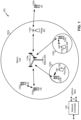
- Fig. 1 is a diagram illustrating a network 100 in which aspects of the present disclosure may be practiced.
- the network 100 may be an LTE network or some other wireless network, such as a 5G or NR network.
- Wireless network 100 may include a number of BSs 110 (shown as BS 110a, BS 110b, BS 110c, and BS 110d) and other network entities.
- a BS is an entity that communicates with user equipment (UEs) and may also be referred to as a base station, a NR BS, a Node B, a gNB, a 5G node B (NB), an access point, a transmit receive point (TRP), and/or the like.
- Each BS may provide communication coverage for a particular geographic area.
- the term "cell" can refer to a coverage area of a BS and/or a BS subsystem serving this coverage area, depending on the context in which the term is used.
- a BS may provide communication coverage for a macro cell, a pico cell, a femto cell, and/or another type of cell.
- a macro cell may cover a relatively large geographic area (e.g., several kilometers in radius) and may allow unrestricted access by UEs with service subscription.
- a pico cell may cover a relatively small geographic area and may allow unrestricted access by UEs with service subscription.
- a femto cell may cover a relatively small geographic area (e.g., a home) and may allow restricted access by UEs having association with the femto cell (e.g., UEs in a closed subscriber group (CSG)).
- a BS for a macro cell may be referred to as a macro BS.
- a BS for a pico cell may be referred to as a pico BS.
- a BS for a femto cell may be referred to as a femto BS or a home BS.
- a BS 110a may be a macro BS for a macro cell 102a
- a BS 110b may be a pico BS for a pico cell 102b
- a BS 110c may be a femto BS for a femto cell 102c.
- a BS may support one or multiple (e.g., three) cells.
- the terms "eNB”, “base station”, “NR BS”, “gNB”, “TRP”, “AP”, “node B", “5G NB”, and “cell” may be used interchangeably herein.
- a cell may not necessarily be stationary, and the geographic area of the cell may move according to the location of a mobile BS.
- the BSs may be interconnected to one another and/or to one or more other BSs or network nodes (not shown) in the access network 100 through various types of backhaul interfaces such as a direct physical connection, a virtual network, and/or the like using any suitable transport network.
- Wireless network 100 may also include relay stations.
- a relay station is an entity that can receive a transmission of data from an upstream station (e.g., a BS or a UE) and send a transmission of the data to a downstream station (e.g., a UE or a BS).
- a relay station may also be a UE that can relay transmissions for other UEs.
- a relay station 110d may communicate with macro BS 110a and a UE 120d in order to facilitate communication between BS 110a and UE 120d.
- a relay station may also be referred to as a relay BS, a relay base station, a relay, etc.
- Wireless network 100 may be a heterogeneous network that includes BSs of different types, e.g., macro BSs, pico BSs, femto BSs, relay BSs, etc. These different types of BSs may have different transmit power levels, different coverage areas, and different impact on interference in wireless network 100.
- macro BSs may have a high transmit power level (e.g., 5 to 40 Watts) whereas pico BSs, femto BSs, and relay BSs may have lower transmit power levels (e.g., 0.1 to 2 Watts).
- a network controller 130 may couple to a set of BSs and may provide coordination and control for these BSs.
- Network controller 130 may communicate with the BSs via a backhaul.
- the BSs may also communicate with one another, e.g., directly or indirectly via a wireless or wireline backhaul.
- UEs 120 may be dispersed throughout wireless network 100, and each UE may be stationary or mobile.
- a UE may also be referred to as an access terminal, a terminal, a mobile station, a subscriber unit, a station, etc.
- a UE may be a cellular phone (e.g., a smart phone), a personal digital assistant (PDA), a wireless modem, a wireless communication device, a handheld device, a laptop computer, a cordless phone, a wireless local loop (WLL) station, a tablet, a camera, a gaming device, a netbook, a smartbook, an ultrabook, medical device or equipment, biometric sensors/devices, wearable devices (smart watches, smart clothing, smart glasses, smart wrist bands, smart jewelry (e.g., smart ring, smart bracelet)), an entertainment device (e.g., a music or video device, or a satellite radio), a vehicular component or sensor, smart meters/sensors, industrial manufacturing equipment, a global positioning system device, or any other suitable device that is configured to communicate via a wireless or wired medium.
- a cellular phone e.g., a smart phone
- PDA personal digital assistant
- WLL wireless local loop
- MTC and eMTC UEs include, for example, robots, drones, remote devices, such as sensors, meters, monitors, location tags, etc., that may communicate with a base station, another device (e.g., remote device), or some other entity.
- a wireless node may provide, for example, connectivity for or to a network (e.g., a wide area network such as Internet or a cellular network) via a wired or wireless communication link.
- Some UEs may be considered Internet-of Things (IoT) devices, and/or may be implemented as may be implemented as NB-IoT (narrowband internet of things) devices.
- Some UEs may be considered a Customer Premises Equipment (CPE).
- UE 120 may be included inside a housing that houses components of UE 120, such as processor components, memory components, and/or the like.
- any number of wireless networks may be deployed in a given geographic area.
- Each wireless network may support a particular RAT and may operate on one or more frequencies.
- a RAT may also be referred to as a radio technology, an air interface, etc.
- a frequency may also be referred to as a carrier, a frequency channel, etc.
- Each frequency may support a single RAT in a given geographic area in order to avoid interference between wireless networks of different RATs.
- NR or 5G RAT networks may be deployed.
- a scheduling entity e.g., a base station
- the scheduling entity may be responsible for scheduling, assigning, reconfiguring, and releasing resources for one or more subordinate entities. That is, for scheduled communication, subordinate entities utilize resources allocated by the scheduling entity.
- Base stations are not the only entities that may function as a scheduling entity. That is, in some examples, a UE may function as a scheduling entity, scheduling resources for one or more subordinate entities (e.g., one or more other UEs). In this example, the UE is functioning as a scheduling entity, and other UEs utilize resources scheduled by the UE for wireless communication.
- a UE may function as a scheduling entity in a peer-to-peer (P2P) network, and/or in a mesh network. In a mesh network example, UEs may optionally communicate directly with one another in addition to communicating with the scheduling entity.
- P2P peer-to-peer
- mesh network UEs may optionally communicate directly with one another in addition to communicating with the scheduling entity.
- a scheduling entity and one or more subordinate entities may communicate utilizing the scheduled resources.
- two or more UEs 120 may communicate directly using one or more sidelink channels (e.g., without using a base station 110 as an intermediary to communicate with one another).
- the UEs 120 may communicate using peer-to-peer (P2P) communications, device-to-device (D2D) communications, a vehicle-to-everything (V2X) protocol (e.g., which may include a vehicle-to-vehicle (V2V) protocol, a vehicle-to-infrastructure (V2I) protocol, and/or the like), a mesh network, and/or the like).
- V2X vehicle-to-everything
- the UE 120 may perform scheduling operations, resource selection operations, and/or other operations described elsewhere herein as being performed by the base station 110.
- a UE 120 may selectively multiplex one or more communications, and the base station 110 may decode received signals based at least in part on whether the communications were multiplexed, as described in more detail elsewhere herein.
- Fig. 1 is provided merely as an example. Other examples are possible and may differ from what was described with regard to Fig. 1 .
- Fig. 2 shows a block diagram of a design 200 of base station 110 and UE 120, which may be one of the base stations and one of the UEs in Fig. 1 .
- Base station 110 may be equipped with T antennas 234a through 234t
- UE 120 may be equipped with R antennas 252a through 252r, where in general T ⁇ 1 and R ⁇ 1.
- a transmit processor 220 may receive data from a data source 212 for one or more UEs, select one or more modulation and coding schemes (MCS) for each UE based at least in part on channel quality indicators (CQIs) received from the UE, process (e.g., encode and modulate) the data for each UE based at least in part on the MCS(s) selected for the UE, and provide data symbols for all UEs. Transmit processor 220 may also process system information (e.g., for semi-static resource partitioning information (SRPI), etc.) and control information (e.g., CQI requests, grants, upper layer signaling, etc.) and provide overhead symbols and control symbols.
- MCS modulation and coding schemes
- CQIs channel quality indicators
- Transmit processor 220 may also process system information (e.g., for semi-static resource partitioning information (SRPI), etc.) and control information (e.g., CQI requests, grants, upper layer signaling, etc.) and provide overhead symbols
- Transmit processor 220 may also generate reference symbols for reference signals (e.g., the cell-specific reference signal (CRS)) and synchronization signals (e.g., the primary synchronization signal (PSS) and secondary synchronization signal (SSS)).
- a transmit (TX) multiple-input multiple-output (MIMO) processor 230 may perform spatial processing (e.g., precoding) on the data symbols, the control symbols, the overhead symbols, and/or the reference symbols, if applicable, and may provide T output symbol streams to T modulators (MODs) 232a through 232t. Each modulator 232 may process a respective output symbol stream (e.g., for OFDM, etc.) to obtain an output sample stream.
- T modulators modulators
- Each modulator 232 may further process (e.g., convert to analog, amplify, filter, and upconvert) the output sample stream to obtain a downlink signal.
- T downlink signals from modulators 232a through 232t may be transmitted via T antennas 234a through 234t, respectively.
- the synchronization signals can be generated with location encoding to convey additional information.
- antennas 252a through 252r may receive the downlink signals from base station 110 and/or other base stations and may provide received signals to demodulators (DEMODs) 254a through 254r, respectively.
- Each demodulator 254 may condition (e.g., filter, amplify, downconvert, and digitize) a received signal to obtain input samples.
- Each demodulator 254 may further process the input samples (e.g., for OFDM, etc.) to obtain received symbols.
- a MIMO detector 256 may obtain received symbols from all R demodulators 254a through 254r, perform MIMO detection on the received symbols if applicable, and provide detected symbols.
- a receive processor 258 may process (e.g., demodulate and decode) the detected symbols, provide decoded data for UE 120 to a data sink 260, and provide decoded control information and system information to a controller/processor 280.
- a channel processor may determine reference signal received power (RSRP), received signal strength indicator (RSSI), reference signal received quality (RSRQ), channel quality indicator (CQI), etc.
- a transmit processor 264 may receive and process data from a data source 262 and control information (e.g., for reports comprising RSRP, RSSI, RSRQ, CQI, etc.) from controller/processor 280. Transmit processor 264 may also generate reference symbols for one or more reference signals. The symbols from transmit processor 264 may be precoded by a TX MIMO processor 266 if applicable, further processed by modulators 254a through 254r (e.g., for DFT-s-OFDM, CP-OFDM, etc.), and transmitted to base station 110.
- control information e.g., for reports comprising RSRP, RSSI, RSRQ, CQI, etc.
- Transmit processor 264 may also generate reference symbols for one or more reference signals.
- the symbols from transmit processor 264 may be precoded by a TX MIMO processor 266 if applicable, further processed by modulators 254a through 254r (e.g., for DFT-s-OFDM, CP-
- the uplink signals from UE 120 and other UEs may be received by antennas 234, processed by demodulators 232, detected by a MIMO detector 236 if applicable, and further processed by a receive processor 238 to obtain decoded data and control information sent by UE 120.
- Receive processor 238 may provide the decoded data to a data sink 239 and the decoded control information to controller/processor 240.
- Base station 110 may include communication unit 244 and communicate to network controller 130 via communication unit 244.
- Network controller 130 may include communication unit 294, controller/processor 290, and memory 292.
- controller/processor 240 of base station 110, controller/processor 280 of UE 120, and/or any other component(s) of Fig. 2 may perform one or more techniques associated with selectively multiplexing PUSCH and PUCCH communications, as described in more detail elsewhere herein.
- controller/processor 240 of base station 110, controller/processor 280 of UE 120, and/or any other component(s) of Fig. 2 may perform or direct operations of, for example, process 1300 of Fig. 13 , process 1400 of Fig. 14 , and/or other processes as described herein.
- Memories 242 and 282 may store data and program codes for base station 110 and UE 120, respectively.
- a scheduler 246 may schedule UEs for data transmission on the downlink and/or uplink.
- the stored program codes when executed by processor 280 and/or other processors and modules at UE 120, may cause the UE 120 to perform operations described with respect to process 1300 of Fig. 13 and/or other processes as described herein.
- the stored program codes when executed by processor 240 and/or other processors and modules at base station 110, may cause the base station 110 to perform operations described with respect to process 1400 of Fig. 14 and/or other processes as described herein.
- a scheduler 246 may schedule UEs for data transmission on the downlink and/or uplink.
- UE 120 may include means for determining that a PUSCH communication, scheduled by an uplink grant, and a PUCCH communication, corresponding to a PDSCH communication scheduled by a downlink grant, are scheduled to overlap in one or more symbols; means for determining a threshold time based at least in part on an earliest scheduled starting time of the PUSCH communication or the PUCCH communication; means for selectively multiplexing the PUSCH communication and the PUCCH communication based at least in part on whether the uplink grant, the downlink grant, and the PDSCH communication are received before the threshold time; means for transmitting the PUSCH communication, the PUCCH communication, or both the PUSCH communication and the PUCCH communication based at least in part on the selective multiplexing; and/or the like.
- such means may include one or more components of UE 120 described in connection with Fig. 2 .
- base station 110 may include means for determining that a PUSCH communication, scheduled by an uplink grant, and a PUCCH communication, corresponding to a PDSCH communication scheduled by a downlink grant, are scheduled to overlap in one or more symbols; means for determining a threshold time based at least in part on an earliest scheduled starting time of the PUSCH communication or the PUCCH communication; means for decoding one or more signals, received in the one or more symbols, based at least in part on whether the uplink grant, the downlink grant, and the PDSCH communication are transmitted before the threshold time; and/or the like.
- such means may include one or more components of base station 110 described in connection with Fig. 2 .
- While blocks in Fig. 2 are illustrated as distinct components, the functions described above with respect to the blocks may be implemented in a single hardware, software, or combination component or in various combinations of components.
- the functions described with respect to the transmit processor 264, the receive processor 258, and/or the TX MIMO processor 266 may be performed by or under the control of processor 280.
- Fig. 2 is provided merely as an example. Other examples are possible and may differ from what was described with regard to Fig. 2 .
- Fig. 3A shows an example frame structure 300 for FDD in a telecommunications system (e.g., NR).
- the transmission timeline for each of the downlink and uplink may be partitioned into units of radio frames.
- Each radio frame may have a predetermined duration and may be partitions into a set of Z (Z ⁇ 1) subframes (e.g., with indices of 0 through Z-1).
- Each subframe may include a set of slots (e.g., two slots per subframe are shown in Fig. 3A ).
- Each slot may include a set of L symbol periods.
- each slot may include seven symbol periods (e.g., as shown in Fig. 3A ), fifteen symbol periods, and/or the like.
- the subframe may include 2L symbol periods, where the 2L symbol periods in each subframe may be assigned indices of 0 through 2L-1.
- a scheduling unit for the FDD may frame-based, subframe-based, slot-based, symbol-based, and/or the like.
- a wireless communication structure may refer to a periodic time-bounded communication unit defined by a wireless communication standard and/or protocol. Additionally, or alternatively, different configurations of wireless communication structures than those shown in Fig. 3A may be used.
- a base station may transmit synchronization signals.
- a base station may transmit a primary synchronization signal (PSS), a secondary synchronization signal (SSS), and/or the like, on the downlink for each cell supported by the base station.
- PSS and SSS may be used by UEs for cell search and acquisition.
- the PSS may be used by UEs to determine symbol timing
- the SSS may be used by UEs to determine a physical cell identifier, associated with the base station, and frame timing.
- the base station may also transmit a physical broadcast channel (PBCH).
- the PBCH may carry some system information, such as system information that supports initial access by UEs.
- the base station may transmit the PSS, the SSS, and/or the PBCH in accordance with a synchronization communication hierarchy (e.g., a synchronization signal (SS) hierarchy) including multiple synchronization communications (e.g., SS blocks), as described below in connection with Fig. 3B .
- a synchronization communication hierarchy e.g., a synchronization signal (SS) hierarchy
- multiple synchronization communications e.g., SS blocks
- Fig. 3B is a block diagram conceptually illustrating an example SS hierarchy, which is an example of a synchronization communication hierarchy.
- the SS hierarchy may include an SS burst set, which may include a plurality of SS bursts (identified as SS burst 0 through SS burst B-1, where B is a maximum number of repetitions of the SS burst that may be transmitted by the base station).
- each SS burst may include one or more SS blocks (identified as SS block 0 through SS block (b max_SS-1 ), where b max_SS-1 is a maximum number of SS blocks that can be carried by an SS burst).
- An SS burst set may be periodically transmitted by a wireless node, such as every X milliseconds, as shown in Fig. 3B .
- an SS burst set may have a fixed or dynamic length, shown as Y milliseconds in Fig. 3B .
- the SS burst set shown in Fig. 3B is an example of a synchronization communication set, and other synchronization communication sets may be used in connection with the techniques described herein.
- the SS block shown in Fig. 3B is an example of a synchronization communication, and other synchronization communications may be used in connection with the techniques described herein.
- an SS block includes resources that carry the PSS, the SSS, the PBCH, and/or other synchronization signals (e.g., a tertiary synchronization signal (TSS)) and/or synchronization channels.
- synchronization signals e.g., a tertiary synchronization signal (TSS)
- multiple SS blocks are included in an SS burst, and the PSS, the SSS, and/or the PBCH may be the same across each SS block of the SS burst.
- a single SS block may be included in an SS burst.
- the SS block may be at least four symbol periods in length, where each symbol carries one or more of the PSS (e.g., occupying one symbol), the SSS (e.g., occupying one symbol), and/or the PBCH (e.g., occupying two symbols).
- the base station may transmit system information, such as system information blocks (SIBs) on a physical downlink shared channel (PDSCH) and/or a physical downlink control channel (PDCCH) in certain subframes.
- SIBs system information blocks
- PDSCH physical downlink shared channel
- PDCCH physical downlink control channel
- the base station may transmit control information/data on a PDCCH in C symbol periods of a subframe, where B may be configurable for each subframe.
- the base station may transmit traffic data and/or other data on the PDSCH and/or the PDCCH in the remaining symbol periods of each subframe.
- Figs. 3A and 3B are provided as examples. Other examples are possible and may differ from what was described with regard to Figs. 3A and 3B .
- Fig. 4 shows an example subframe format 410 with a normal cyclic prefix.
- the available time frequency resources may be partitioned into resource blocks.
- Each resource block may cover a set to of subcarriers (e.g., 12 subcarriers) in one slot and may include a number of resource elements.
- Each resource element may cover one subcarrier in one symbol period (e.g., in time) and may be used to send one modulation symbol, which may be a real or complex value.
- subframe format 410 may be used for transmission of SS blocks that carry the PSS, the SSS, the PBCH, and/or the like, as described herein.
- An interlace structure may be used for each of the downlink and uplink for FDD in certain telecommunications systems (e.g., NR).
- Q interlaces with indices of 0 through Q - 1 may be defined, where Q may be equal to 4, 6, 8, 10, or some other value.
- Each interlace may include subframes that are spaced apart by Q frames.
- interlace q may include subframes q, q + Q, q + 2Q, etc., where q ⁇ ⁇ 0,...,Q-1 ⁇ .
- New radio may refer to radios configured to operate according to a new air interface (e.g., other than Orthogonal Frequency Divisional Multiple Access (OFDMA)-based air interfaces) or fixed transport layer (e.g., other than Internet Protocol (IP)).
- OFDM Orthogonal Frequency Divisional Multiple Access
- IP Internet Protocol
- NR may utilize OFDM with a CP (herein referred to as cyclic prefix OFDM or CP-OFDM) and/or SC-FDM on the uplink, may utilize CP-OFDM on the downlink and include support for half-duplex operation using TDD.
- NR may, for example, utilize OFDM with a CP (herein referred to as CP-OFDM) and/or discrete Fourier transform spread orthogonal frequency-division multiplexing (DFT-s-OFDM) on the uplink, may utilize CP-OFDM on the downlink and include support for half-duplex operation using TDD.
- NR may include Enhanced Mobile Broadband (eMBB) service targeting wide bandwidth (e.g., 80 megahertz (MHz) and beyond), millimeter wave (mmW) targeting high carrier frequency (e.g., 60 gigahertz (GHz)), massive MTC (mMTC) targeting non-backward compatible MTC techniques, and/or mission critical targeting ultra reliable low latency communications (URLLC) service.
- eMBB Enhanced Mobile Broadband
- mmW millimeter wave
- mMTC massive MTC
- URLLC ultra reliable low latency communications
- NR resource blocks may span 12 sub-carriers with a sub-carrier bandwidth of 60 or 120 kilohertz (kHz) over a 0.1 millisecond (ms) duration.
- Each radio frame may include 40 subframes with a length of 10 ms. Consequently, each subframe may have a length of 0.25 ms.
- Each subframe may indicate a link direction (e.g., DL or UL) for data transmission and the link direction for each subframe may be dynamically switched.
- Each subframe may include DL/UL data as well as DL/UL control data.
- NR may support a different air interface, other than an OFDM-based interface.
- NR networks may include entities such central units or distributed units.
- Fig. 4 is provided as an example. Other examples are possible and may differ from what was described with regard to Fig. 4 .
- Fig. 5 is a diagram 500 showing an example of a DL-centric slot, subframe, or other wireless communication structure or transmission time interval (TTI) (referred to in connection with Fig. 5 as a DL-centric subframe).
- the DL-centric subframe may include a control portion 502.
- the control portion 502 may exist in the initial or beginning portion of the DL-centric subframe.
- the control portion 502 may include various scheduling information and/or control information corresponding to various portions of the DL-centric subframe.
- the control portion 502 may be a physical DL control channel (PDCCH), as indicated in Fig. 5 .
- PDCH physical DL control channel
- control portion 502 may include legacy PDCCH information, shortened PDCCH (sPDCCH) information), a control format indicator (CFI) value (e.g., carried on a physical control format indicator channel (PCFICH)), one or more grants (e.g., downlink grants, uplink grants, etc.), and/or the like.
- legacy PDCCH information shortened PDCCH (sPDCCH) information
- CFI control format indicator
- PCFICH physical control format indicator channel
- grants e.g., downlink grants, uplink grants, etc.
- the DL-centric subframe may also include a DL data portion 504.
- the DL data portion 504 may sometimes be referred to as the payload of the DL-centric subframe.
- the DL data portion 504 may include the communication resources utilized to communicate DL data from the scheduling entity (e.g., UE or BS) to the subordinate entity (e.g., UE).
- the DL data portion 504 may be a physical DL shared channel (PDSCH).
- PDSCH physical DL shared channel
- the DL-centric subframe may also include an UL short burst portion 506.
- the UL short burst portion 506 may sometimes be referred to as an UL burst, an UL burst portion, a common UL burst, a short burst, an UL short burst, a common UL short burst, a common UL short burst portion, and/or various other suitable terms.
- the UL short burst portion 506 may include one or more reference signals. Additionally, or alternatively, the UL short burst portion 506 may include feedback information corresponding to various other portions of the DL-centric subframe.
- the UL short burst portion 506 may include feedback information corresponding to the control portion 502 and/or the data portion 504.
- information that may be included in the UL short burst portion 506 include an ACK signal (e.g., a PUCCH ACK, a PUSCH ACK, an immediate ACK), a NACK signal (e.g., a PUCCH NACK, a PUSCH NACK, an immediate NACK), a scheduling request (SR), a buffer status report (BSR), a HARQ indicator, a channel state indication (CSI), a channel quality indicator (CQI), a sounding reference signal (SRS), a demodulation reference signal (DMRS), PUSCH data, and/or various other suitable types of information.
- the UL short burst portion 506 may include additional or alternative information, such as information pertaining to random access channel (RACH) procedures, scheduling requests, and various other suitable types of information.
- RACH random access channel
- the end of the DL data portion 504 may be separated in time from the beginning of the UL short burst portion 506.
- This time separation may sometimes be referred to as a gap, a guard period, a guard interval, and/or various other suitable terms.
- This separation provides time for the switch-over from DL communication (e.g., reception operation by the subordinate entity (e.g., UE)) to UL communication (e.g., transmission by the subordinate entity (e.g., UE)).
- DL communication e.g., reception operation by the subordinate entity (e.g., UE)
- UL communication e.g., transmission by the subordinate entity (e.g., UE)
- Fig. 5 is provided merely as an example. Other examples are possible and may differ from what was described with regard to Fig. 5 .
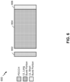
- Fig. 6 is a diagram 600 showing an example of an UL-centric slot, subframe, or other wireless communication structure or transmission time interval (TTI) (referred to in connection with Fig. 6 as an UL-centric subframe).
- the UL-centric subframe may include a control portion 602.
- the control portion 602 may exist in the initial or beginning portion of the UL-centric subframe.
- the control portion 602 in Fig. 6 may be similar to the control portion 502 described above with reference to Fig. 5 .
- the UL-centric subframe may also include an UL long burst portion 604.
- the UL long burst portion 604 may sometimes be referred to as the payload of the UL-centric subframe.
- the UL portion may refer to the communication resources utilized to communicate UL data from the subordinate entity (e.g., UE) to the scheduling entity (e.g., UE or BS).
- the control portion 602 may be a physical DL control channel (PDCCH).
- the end of the control portion 602 may be separated in time from the beginning of the UL long burst portion 604. This time separation may sometimes be referred to as a gap, guard period, guard interval, and/or various other suitable terms. This separation provides time for the switch-over from DL communication (e.g., reception operation by the scheduling entity) to UL communication (e.g., transmission by the scheduling entity).
- DL communication e.g., reception operation by the scheduling entity
- UL communication e.g., transmission by the scheduling entity
- the UL-centric subframe may also include an UL short burst portion 606.
- the UL short burst portion 606 in Fig. 6 may be similar to the UL short burst portion 506 described above with reference to Fig. 5 , and may include any of the information described above in connection with Fig. 5 .
- the foregoing is merely one example of an UL-centric wireless communication structure, and alternative structures having similar features may exist without necessarily deviating from the aspects described herein.
- a wireless communication structure such as a frame, may include both UL-centric subframes and DL-centric subframes.
- the ratio of UL-centric subframes to DL-centric subframes in a frame may be dynamically adjusted based at least in part on the amount of UL data and the amount of DL data that are transmitted. For example, if there is more UL data, then the ratio of UL-centric subframes to DL-centric subframes may be increased. Conversely, if there is more DL data, then the ratio of UL-centric subframes to DL-centric subframes may be decreased.
- Fig. 6 is provided merely as an example. Other examples are possible and may differ from what was described with regard to Fig. 6 .
- a UE 120 may multiplex communications on different physical channels.
- the UE 120 may multiplex a PUCCH communication (e.g., that includes uplink control information (UCI), such as acknowledgment or negative acknowledgement (ACK/NACK) feedback and/or the like) and a PUSCH communication.
- UCI uplink control information
- ACK/NACK acknowledgment or negative acknowledgement
- the UE 120 may multiplex the PUCCH communication and the PUSCH communication by piggybacking the PUCCH communication in the PUSCH communication, which may include puncturing (e.g., dropping) one or more bits of the PUSCH communication and replacing the punctured PUSCH bit(s) with bit(s) of the PUCCH communication and/or which may include rate-matching one or more bits of the PUSCH communication around UCI bits of the PUCCH communication.
- puncturing e.g., dropping
- bit(s) of the PUCCH communication may include rate-matching one or more bits of the PUSCH communication around UCI bits of the PUCCH communication.
- the UE 120 may not have sufficient time to process the PUSCH communication and/or the PUCCH communication in order to perform such multiplexing. In this case, the UE 120 may not be capable of performing such multiplexing, which may result in decoding errors at the base station 110 if the base station 110 and the UE 120 do not apply the same rules to multiplexing.
- Techniques and apparatuses described herein permit the UE 120 and the base station 110 to apply a consistent set of rules to PUSCH and PUCCH multiplexing, thereby reducing errors, achieving performance improvements when such multiplexing is possible, and/or the like.
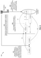
- Fig. 7 is a diagram illustrating an example 700 of selectively multiplexing PUSCH and PUCCH communications, in accordance with various aspects of the present disclosure.
- a UE 120 may determine that a PUSCH communication and a PUCCH communication are scheduled to overlap in one or more symbols. For example, a PUSCH communication may cross a boundary of an UL long burst portion 604 (described above in connection with Fig. 6 ) and may be scheduled to occur in one or more symbols of an UL short burst portion 606 in which the PUCCH communication is scheduled. In some aspects, the UE 120 may make this determination based at least in part on scheduling information received in PDCCH communications that schedule the PUSCH communication and the PUCCH communication (e.g., using downlink control information (DCI)).
- DCI downlink control information
- the UE 120 may make this determination based at least in part on scheduling information received in connection with semi-persistent scheduling, configured scheduling, and/or the like (e.g., using DCI and/or a radio resource control (RRC) message).
- RRC radio resource control
- the PUSCH communication and the PUCCH communication may be included in the same PUCCH group.
- the PUSCH communication and the PUCCH communication may be transmitted on the same carrier (e.g., component carrier).
- the PUSCH communication and the PUCCH communication may be transmitted on different carriers that are included in the same PUCCH group.
- a PUCCH group may refer to a group of carriers that includes a primary carrier and one or more secondary carriers. The primary carrier may be used for all PUCCH communications for the PUCCH group.
- piggybacking may refer to puncturing the PUSCH communication with the PUCCH communication by replacing one or more bits of the PUSCH communication with one or more bits of the PUCCH communication.
- piggybacking may refer to rate-matching the PUSCH communication around the uplink control information (UCI) bits corresponding to the PUCCH communication. In this way, UCI of the PUCCH communication may be transmitted on the PUSCH.
- UCI uplink control information
- the PUSCH communication may be scheduled by a PDCCH communication that includes an uplink grant.
- the uplink grant may indicate a timing between the PDCCH communication and transmission of the PUSCH communication scheduled by the PDCCH communication (e.g., which may be referred to as a K2 value in the 3GPP specification).
- the PUCCH communication may be scheduled by a PDCCH communication that includes a downlink grant.
- the downlink grant may indicate a timing between the PDCCH communication and a PDSCH communication scheduled by the PDCCH communication (e.g., which may be referred to as a K0 value in the 3GPP specification), and may indicate a timing between the PDSCH communication and a corresponding PUCCH communication that includes ACK/NACK feedback for the PDSCH communication (e.g., which may be referred to as a K1 value in the 3GPP specification).
- the timing may indicate, for example, a number of slots, a number of uplink opportunities, a number of PDSCH opportunities, a number of PUCCH opportunities, and/or the like.
- the UE 120 may determine a threshold time (e.g., a threshold symbol, a threshold symbol boundary, and/or the like) based at least in part on an earliest scheduled starting time of the PUSCH communication or the PUCCH communication.
- a threshold time e.g., a threshold symbol, a threshold symbol boundary, and/or the like
- the PUSCH communication and the PUCCH communication may be scheduled to start in a same symbol, in which case the earliest scheduled starting time may be that same symbol.
- the PUSCH communication and the PUCCH communication may be scheduled to start in different symbols, in which case the earliest scheduled starting time may be the initial symbol of whichever one of the PUSCH communication or the PUCCH communication that starts in an earlier symbol. For example, if the PUSCH communication is scheduled to start in an earlier symbol than the PUCCH communication, then the earliest scheduled starting time may be a scheduled starting time of the PUSCH communication. Conversely, if the PUCCH communication is scheduled to start in an earlier symbol than the PUSCH communication, then the earliest scheduled starting time may be a scheduled starting time of the PUCCH communication.
- the UE 120 may determine the threshold time based at least in part on a PUSCH processing time (e.g., which may be referred to as an N2 value in the 3GPP specification).
- the PUSCH processing time may be a minimum processing time required to process a PUSCH communication prior to transmission by the UE 120.
- the UE 120 may determine the threshold time based at least in part on a PUCCH processing time (e.g., which may be referred to as an N1 value in the 3GPP specification).
- the PUCCH processing time may be a minimum processing time required to process a PUCCH communication prior to transmission by the UE 120. Additional details are described below in connection with Figs. 9 and 10 .
- the UE 120 may selectively multiplex (e.g., multiplex or not multiplex) the PUSCH communication and the PUCCH communication based at least in part on whether the uplink grant, the downlink grant, and a PDSCH communication, corresponding to the PUCCH communication, are received before the threshold time.
- multiplexing may include piggybacking uplink control information of the PUCCH communication in the PUSCH communication by puncturing the PUSCH communication and/or by rate-matching the PUSCH communication around the UCI bits of the PUCCH communication.
- the UE 120 may multiplex the PUSCH communication and the PUCCH communication based at least in part on a determination that the uplink grant, the downlink grant, and a last symbol (e.g., at least a last symbol, and possibly one or more other symbols) of the PDSCH communication are received before the threshold time. In this case, when all of these communications are received before the threshold time, then the UE 120 may have sufficient time to process the PUSCH communication and the PUCCH communication to permit such multiplexing. In this way, the UE 120 may conserve network resources, reduce latency, and/or the like due to such multiplexing.
- a last symbol e.g., at least a last symbol, and possibly one or more other symbols
- the UE 120 may prevent multiplexing of the PUSCH communication and the PUCCH communication based at least in part on a determination that at least one of the uplink grant, the downlink grant, or a last symbol of the PDSCH communication is received after the threshold time. In this case, the UE 120 may not have sufficient time to process the PUSCH communication and the PUCCH communication to permit such multiplexing, and may prevent such multiplexing from occurring to reduce errors (e.g., decoding errors at a base station 110 that receives the signal(s) transmitted by the UE 120 in the overlapping symbols).
- errors e.g., decoding errors at a base station 110 that receives the signal(s) transmitted by the UE 120 in the overlapping symbols).
- the UE 120 may not have sufficient time to piggyback the PUCCH communication (e.g., ACK/NACK feedback) in the PUSCH communication.
- the PUCCH communication e.g., ACK/NACK feedback
- the UE 120 may drop both the PUSCH communication and the PUCCH communication based at least in part on a determination that at least one of the uplink grant, the downlink grant, or a last symbol of the PDSCH communication is received after the threshold time. For example, this situation may not be permitted (e.g., by a 3GPP specification), and if such a situation occurs, then the UE 120 may be configured to indicate an error and/or drop both the PUSCH communication and the PUCCH communication.
- the UE 120 may transmit only one of either the PUSCH communication or the PUCCH communication, and may drop the other of the PUSCH communication of the PUCCH communication, based at least in part on a determination that at least one of the uplink grant, the downlink grant, or a last symbol of the PDSCH communication is received after the threshold time. For example, if these communications are not received before the threshold time, then the UE 120 may transmit the PUSCH communication, and may drop the PUCCH communication. Alternatively, if these communications are not received before the threshold time, then the UE 120 may transmit the PUCCH communication, and may drop the PUSCH communication.
- the UE 120 may transmit the communication (e.g., the PUSCH communication or the PUCCH communication) that is scheduled to start in an earlier symbol, and may drop the communication that is scheduled to start in a later symbol.
- the UE 120 may transmit the communication that is scheduled to start in a later symbol, and may drop the communication that is scheduled to start in an earlier symbol.
- the UE 120 may receive an indication from a base station 110 (e.g., in an RRC message, DCI, and/or the like) of which communication is to be transmitted and which communication is to be dropped (e.g., the PUSCH communication, the PUCCH communication, the communication that starts in the earlier symbol, the communication that starts in the later symbol, and/or the like).
- a base station 110 e.g., in an RRC message, DCI, and/or the like
- the UE 120 may be flexibly configured for different requirements (e.g., a latency requirement, a reliability requirement, and/or the like), different types of operations (e.g., URLLC, eMBB), different loads on the base station 110, different channel conditions, and/or the like.
- Fig. 7 shows selective multiplexing of a single PUSCH communication and a single PUCCH communication
- the UE 120 may selectively multiplex a single PUSCH communication and multiple PUCCH communications, may selectively multiplex multiple PUSCH communications and a single PUCCH communication, or may selectively multiplex multiple PUSCH communications and multiple PUCCH communications. Additional details are described below in connection with Figs. 11 and 12 .
- the UE 120 may conserve network resources, reduce latency, and/or the like. Furthermore, by preventing such piggybacking from occurring when the UE 120 does not have sufficient time to perform such piggybacking, the UE 120 may reduce and/or prevent errors.
- Fig. 7 is provided as an example. Other examples are possible and may differ from what was described with respect to Fig. 7 .
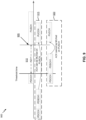
- Fig. 8 is a diagram illustrating another example 800 of selectively multiplexing PUSCH and PUCCH communications, in accordance with various aspects of the present disclosure.
- a base station 110 may determine that a PUSCH communication and a PUCCH communication are scheduled to overlap in one or more symbols, in a similar manner as described above in connection with Fig. 7 .
- the base station 110 may make this determination based at least in part on scheduling information transmitted in PDCCH communications that schedule the PUSCH communication and the PUCCH communication (e.g., using downlink control information (DCI)).
- DCI downlink control information
- the base station 110 may make this determination based at least in part on scheduling information transmitted in connection with semi-persistent scheduling, configured scheduling, and/or the like (e.g., using DCI and/or a radio resource control (RRC) message).
- DCI downlink control information
- RRC radio resource control
- the PUSCH communication and the PUCCH communication may be included in the same PUCCH group, as described above in connection with Fig. 7 .
- the PUSCH communication may be scheduled by a PDCCH communication that includes an uplink grant, as described above in connection with Fig. 7 .
- the PUCCH communication may be scheduled by a PDCCH communication that includes a downlink grant, as described above in connection with Fig. 7 .
- the base station 110 may determine a threshold time based at least in part on an earliest scheduled starting time of the PUSCH communication or the PUCCH communication, as described above in connection with Fig. 7 .
- the base station 110 may determine the threshold time based at least in part on a PUSCH processing time and/or a PUCCH processing time, as described above in connection with Fig. 7 . Additional details regarding determining the threshold time are described below in connection with Figs. 9 and 10 .
- the PUSCH processing time and/or the PUCCH processing time for the UE 120 may be indicated by the UE 120 to the base station 110 (e.g., in an RRC message, in a capability report, and/or the like).
- the base station 110 may decode one or more signals (e.g., at least a portion of only the PUSCH communication, only the PUCCH communication, or both the PUSCH communication and the PUCCH communication) based at least in part on whether the uplink grant, the downlink grant, and a PDSCH communication, corresponding to the PUCCH communication, are transmitted before the threshold time and/or are scheduled to be received by the UE 120 before the threshold time.
- one or more signals e.g., at least a portion of only the PUSCH communication, only the PUCCH communication, or both the PUSCH communication and the PUCCH communication
- the UE 120 may multiplex the PUSCH communication and the PUCCH communication based at least in part on a determination that the uplink grant, the downlink grant, and a last symbol (e.g., at least a last symbol, and possibly one or more other symbols) of the PDSCH communication are received by the UE 120 before the threshold time. In this case, when all of these communications are transmitted by the base station 110 before the threshold time, then the base station 110 may assume such multiplexing when decoding the one or more symbols. In this way, the UE 120 and the base station 110 may conserve network resources, reduce latency, and/or the like due to such multiplexing.
- a last symbol e.g., at least a last symbol, and possibly one or more other symbols
- the UE 120 may prevent multiplexing of the PUSCH communication and the PUCCH communication based at least in part on a determination that at least one of the uplink grant, the downlink grant, or a last symbol of the PDSCH communication is received by the UE 120 after the threshold time. In this case, when all of these communications are not transmitted by the base station 110 before the threshold time, then the base station 110 may assume that the PUSCH communication and the PUCCH communication are not multiplexed when decoding the one or more symbols. In this way, decoding errors may be reduced, which may conserve processing and memory resources.
- the UE 120 may not have sufficient time to piggyback the PUCCH communication (e.g., ACK/NACK feedback) in the PUSCH communication, and the base station 110 may decode signal(s) received in the overlapping symbol(s) accordingly.
- the PUCCH communication e.g., ACK/NACK feedback
- the UE 120 may drop both the PUSCH communication and the PUCCH communication. In this case, the base station 110 may ignore (e.g., skip decoding of) one or more signals received in the one or more symbols.
- the UE 120 may transmit only one of either the PUSCH communication or the PUCCH communication, and may drop the other of the PUSCH communication of the PUCCH communication. Additionally, or alternatively, the UE 120 may transmit only one of either the communication that is scheduled to start in an earlier symbol or the communication that is scheduled to start in a later symbol, and may drop the other of the communication that is scheduled to start in the earlier symbol or the communication that is scheduled to start in the later symbol. In either case, the base station 110 may decode and/or interpret signal(s) received in the overlapping symbol(s) based at least in part on a determination of which communication is transmitted by the UE 120.
- the base station 110 and the UE 120 may both store information regarding which communication is to be transmitted. For example, such information may be hard coded in memory of the base station 110 and/or the UE 120 according to a 3GPP specification. Additionally, or alternatively, the base station 110 may transmit, to the UE 120, an indication of which communication is to be transmitted and which communication is to be dropped. In this way, the UE 120 may be flexibly configured for different requirements (e.g., a latency requirement, a reliability requirement, and/or the like), different types of operations (e.g., URLLC, eMBB), different loads on the base station 110, different channel conditions, and/or the like.
- requirements e.g., a latency requirement, a reliability requirement, and/or the like
- different types of operations e.g., URLLC, eMBB
- Fig. 8 describes decoding with respect to a single PUSCH communication and a single PUCCH communication
- the base station 110 may decode with respect to a single PUSCH communication and multiple PUCCH communications, may decode with respect to multiple PUSCH communications and a single PUCCH communication, or may decode with respect to multiple PUSCH communications and multiple PUCCH communications. Additional details are described below in connection with Figs. 11 and 12 .
- Fig. 8 is provided as an example. Other examples are possible and may differ from what was described with respect to Fig. 8 .
- Fig. 9 is a diagram illustrating another example 900 of selectively multiplexing PUSCH and PUCCH communications, in accordance with various aspects of the present disclosure.
- the PUSCH communication may be scheduled to start in an earlier symbol than the PUCCH communication.
- the UE 120 and/or the base station 110 may determine the threshold time based at least in part on a PUSCH processing time (e.g., N2) and/or a scheduled starting time of the PUSCH communication.
- a PUSCH processing time e.g., N2
- the threshold time may be computed as a threshold symbol (e.g., rather than a symbol boundary), and the PUSCH processing time may be N2 symbols in length. In this case, the threshold time may be N2+1 symbols before the initial symbol (e.g., the first symbol in time) of the PUSCH communication, as shown by reference number 910. In this case, if the threshold time is determined from the PUSCH processing time (e.g., because the PUSCH communication occurs first), then the downlink grant corresponding to the PUCCH communication and the last symbol of the PDSCH communication corresponding to the PUCCH communication should occur in or before a symbol that is N2+1 symbols before the initial symbol of the PUSCH communication in order to permit sufficient processing time for multiplexing.
- the UE 120 if the downlink grant and the last symbol of the PDSCH communication occur in or before a symbol that is N2+1 symbols before the initial symbol of the PUSCH communication, then this allows the UE 120 to process the PUSCH communication in the N2 symbols prior to the initial symbol of the PUSCH communication, and to multiplex the PUCCH communication with the PUSCH communication.
- the downlink grant or the last symbol of the PDSCH communication occur after a symbol that is N2+1 symbols before the initial symbol of the PUSCH communication, then this does not allow the UE 120 to process the PUSCH communication in the N2 symbols prior to the initial symbol of the PUSCH communication, and the UE 120 will not be capable of multiplexing the PUCCH communication with the PUSCH communication.
- Fig. 9 is provided as an example. Other examples are possible and may differ from what was described with respect to Fig. 9 .
- Fig. 10 is a diagram illustrating another example 1000 of selectively multiplexing PUSCH and PUCCH communications, in accordance with various aspects of the present disclosure.
- the PUCCH communication may be scheduled to start in an earlier symbol than the PUSCH communication.
- the UE 120 and/or the base station 110 may determine the threshold time based at least in part on a PUCCH processing time (e.g., N1), a duration of the PDSCH communication corresponding to the PUCCH communication (and/or a preconfigured default duration), and/or a scheduled starting time of the PUCCH communication.
- a PUCCH processing time e.g., N1
- a duration of the PDSCH communication corresponding to the PUCCH communication and/or a preconfigured default duration
- a scheduled starting time of the PUCCH communication e.g., N1
- the threshold time may be computed as a threshold symbol (e.g., rather than a symbol boundary), and the PUCCH processing time may be N1 symbols in length.
- the threshold time may be N1 symbols plus a number of symbols of the PDSCH communication before the initial symbol of the PUCCH communication, as shown by reference number 1010.
- the uplink grant corresponding to the PUSCH communication should occur in or before a symbol that is N1+N PDSCH symbols before the initial symbol of the PUCCH communication in order to permit sufficient processing time for multiplexing (e.g., where N PDSCH is the number of symbols in the PDSCH communication).
- the uplink grant occurs in or before a symbol that is N1+N PDSCH symbols before the initial symbol of the PUCCH communication, then this allows the UE 120 to process the PUCCH communication prior to the initial symbol of the PUCCH communication, and to multiplex the PUCCH communication with the PUSCH communication.
- the uplink grant occurs after a symbol that is N1+N PDSCH symbols before the initial symbol of the PUCCH communication, then this does not allow the UE 120 to process the PUCCH communication prior to the initial symbol of the PUCCH communication, and the UE 120 will not be capable of multiplexing the PUCCH communication with the PUSCH communication.
- the threshold time may be determined based at least in part on a preconfigured value (e.g., a preconfigured number of symbols).
- the threshold time may be N1 symbols plus the preconfigured number of symbols before the initial symbol of the PUCCH communication.
- the threshold time may be N1 symbols plus a maximum value between N PDSCH and the preconfigured number of symbols (e.g., max ⁇ N PDSCH , N preconfigured ⁇ ) before the initial symbol of the PUCCH communication. This may permit sufficient processing time by using the PDSCH duration when the PDSCH is long, and by using the preconfigured value when the PDSCH is short.
- the preconfigured number of symbols may be 7 symbols (e.g., to permit sufficient processing time).
- the preconfigured number of symbols may be a different number of symbols (e.g., 6 symbols, 8 symbols, and/or the like).
- the threshold time may be determined based at least in part on a determination of whether the PUSCH communication or the PUCCH communication is scheduled to start in an earlier symbol. For example, if the PUSCH communication is scheduled to start in an earlier symbol, then the threshold time may be determined based at least in part on a PUSCH processing time, as described above in connection with Fig. 9 . Conversely, if the PUCCH communication is scheduled to start in an earlier symbol, then the threshold time may be determined based at least in part on a PUCCH processing time, as described above in connection with Fig. 10 .
- the threshold time may be determined as a maximum value of a first threshold time determined based at least in part on the PUSCH processing time and a second threshold time determined based at least in part on the PUCCH processing time.
- the same threshold time may be used regardless of which of the PUSCH communication or the PUCCH communication is scheduled to start in an earlier symbol.
- the threshold time may be determined as a maximum value of the first threshold time and the second threshold time described above.
- the first threshold time e.g., N2+1
- the second threshold time e.g., N1 + max ⁇ N PDSCH , N preconfigured ⁇
- Fig. 10 is provided as an example. Other examples are possible and may differ from what was described with respect to Fig. 10 .
- Fig. 11 is a diagram illustrating another example 1100 of selectively multiplexing PUSCH and PUCCH communications, in accordance with various aspects of the present disclosure.
- the UE 120 may determine that there are multiple PUCCH communications to be potentially (e.g., selectively) multiplexed with a PUSCH communication (e.g., that overlap with one or more symbols of the PUSCH communication).
- the PUSCH communication may start in an earlier symbol than all of the multiple PUCCH communications. In this case, if all of the PDSCH communications corresponding to the PUCCH communications are received before the threshold time, then the UE 120 may multiplex ACK/NACK feedback, for the multiple PDSCH communications, in the PUSCH communication.
- a first PDSCH communication may be received before the threshold time and at least a last symbol of a second PDSCH communication may be received after the threshold time.
- the UE 120 may be able to multiplex a first PUCCH communication (e.g., first ACK/NACK feedback), corresponding to the first PDSCH communication, but may not be able to multiplex a second PUCCH communication (e.g., second ACK/NACK feedback) corresponding to the second PDSCH communication.
- a first PUCCH communication e.g., first ACK/NACK feedback
- second PUCCH communication e.g., second ACK/NACK feedback
- a first downlink grant 1110 may schedule a first PDSCH communication 1115 and a first PUCCH communication 1120. As shown, the first downlink grant 1110 and a last symbol of the first PDSCH communication 1115 are received before the threshold time. As further shown, a second downlink grant 1125, that schedules a second PDSCH communication 1130 and a second PUCCH communication 1135, may be received before the threshold time, and a last symbol of the second PDSCH communication 1130 may be received after the threshold time.
- the UE 120 may multiplex a NACK, corresponding to the second PUCCH communication 1135, with the PUSCH communication and the first PUCCH communication 1120 based at least in part on a determination that the second downlink grant 1125 is received before the threshold time and that a last symbol of the second PDSCH communication 1130 is received after the threshold time.
- the UE 120 may be configured to use a downlink assignment index (DAI), indicated in the second downlink grant 1125, for multiplexing of ACK/NACK feedback.
- DAI downlink assignment index
- the UE 120 may multiplex the NACK because the UE 120 does not have sufficient processing time to determine whether the second PDSCH communication 1130 is to be ACKed or NACKed.
- the UE 120 may ignore (e.g., skip decoding of) a retransmission of the second PDSCH communication 1130 triggered by the NACK, thereby saving energy of the UE 120.
- the UE 120 may drop the second PUCCH communication 1135 based at least in part on a determination that the second downlink grant 1125 is received before the threshold time and that a last symbol of the second PDSCH communication 1130 is received after the threshold time.
- the UE 120 may be configured to use a DAI, indicated in the first downlink grant 1110, for multiplexing of ACK/NACK feedback. In this way, reliability may be improved by preventing the PUSCH communication from being punctured with a NACK without a determination of whether the NACK or an ACK should be transmitted.
- the UE 120 may multiplex an ACK, corresponding to the second PUCCH communication 1135, with the PUSCH communication and the first PUCCH communication 1120 based at least in part on a determination that a PDCCH communication (e.g., which may or may not include the downlink grant 1125), that schedules the second PUCCH communication 1135, is received before the threshold time and that the PDCCH communication does not schedule a PDSCH communication.
- the PDCCH communication may be used to signal bandwidth part switching, to active or deactivate (e.g., release) a configuration (e.g., semi-persistent scheduling, configured scheduling, and/or the like), and/or for another purpose other than scheduling a PDSCH communication.
- the UE 120 may multiplex an ACK of the PDCCH communication if the PDCCH communication is successfully received, or may multiplex a NACK of the PDCCH communication if the PDCCH communication is not successfully received.
- a first downlink grant 1145 may schedule a first PDSCH communication 1150 and a first PUCCH communication 1155. As shown, the first downlink grant 1145 and a last symbol of the first PDSCH communication 1150 are received before the threshold time. As further shown, a second downlink grant 1160, that schedules a second PDSCH communication 1165 and a second PUCCH communication 1170, may be received after the threshold time.
- the UE 120 may drop the second PUCCH communication 1170 based at least in part on a determination that the second downlink grant 1160 is received after the threshold time.
- the UE 120 may be configured to use a DAI, indicated in the first downlink grant 1145, for multiplexing of ACK/NACK feedback. In this way, reliability may be improved by preventing the PUSCH communication from being punctured with the second PUCCH communication without a determination of whether the second PUCCH communication should include an ACK or a NACK.
- Fig. 11 While operations of Fig. 11 are described in connection with a UE 120, similar operations may be performed by a base station 110, in a similar manner as described above in connection with Fig. 8 .
- the base station 110 and the UE 120 may store a same set of rules regarding handling of ACK/NACK feedback so that ACK/NACK feedback transmitted by the UE 120 may be appropriately decoded and/or interpreted by the base station 110.
- one or more of these rules may be hard coded in memory of the base station 110 and/or the UE 120 (e.g., based at least in part on a 3GPP specification). Additionally, or alternatively, one or more of these rules may be indicated to the UE 120 by the base station 110 (e.g., in an RRC message, in DCI, and/or the like). In this way, the UE 120 may be flexibly configured.
- Fig. 11 is provided as an example. Other examples are possible and may differ from what was described with respect to Fig. 11 .
- Fig. 12 is a diagram illustrating another example 1200 of selectively multiplexing PUSCH and PUCCH communications, in accordance with various aspects of the present disclosure.
- the UE 120 may determine that there are multiple PUSCH communications 1205 (e.g., shown as a first PUSCH communication 1205-1 and a second PUSCH communication 1205-2) to be multiplexed with a PUCCH communication 1210 (e.g., that overlap with one or more symbols of the PUCCH communication 1210).
- the PUCCH communication 1210 may start in an earlier symbol than all of the multiple PUSCH communications 1205. In this case, if all of the uplink grants 1215 corresponding to the PUSCH communications 1205 are received before the threshold time, then the UE 120 may multiplex the PUCCH communication 1210 with one or more of the multiple PUSCH communications 1205.
- the UE 120 may determine which of the multiple PUSCH communications 1205 has an earliest starting symbol, and may piggyback the PUCCH communication 1210 in the PUSCH communication 1205 that has the earliest starting symbol. For example, in example 1200, the UE 120 may piggyback the PUCCH communication 1210 in the first PUSCH communication 1205-1. In some aspects, the UE 120 may not piggyback the PUCCH communication 1210 in the second PUSCH communication 1205-2 (e.g., that has the later starting symbol). In this way, latency for the PUCCH may be reduced.
- the UE 120 may determine which of the multiple PUSCH communications 1205 has the largest number of assigned resources, and may piggyback the PUCCH communication 1210 in the PUSCH communication 1205 that has the largest number of assigned resources. In this way, reliability may be enhanced by puncturing or occupying a smaller ratio of resources of a PUSCH communication 1205.
- the UE 120 may piggyback the PUCCH communication 1210 in multiple PUSCH communications 1205.
- the UE 120 may piggyback the PUCCH communication 1210 in both the first PUSCH communication 1205-1 and the second PUSCH communication 1205-2.
- the UE 120 may apply one or more rules of piggybacking UCI on the PUSCH with frequency hopping.
- the multiple PUSCH communications 1205 may be treated as different frequency hops of one PUSCH for the purpose of applying these rule(s), even if none of the PUSCH communications 1205 are configured with frequency hopping. In this way, the likelihood of a base station 110 receiving the PUCCH communication 1210 may be increased.
- Fig. 12 While operations of Fig. 12 are described in connection with a UE 120, similar operations may be performed by a base station 110, in a similar manner as described above in connection with Fig. 8 .
- the base station 110 and the UE 120 may store a same set of rules regarding multiplexing a PUCCH communication with respect to multiple overlapping PUSCH communications so that information transmitted by the UE 120 in overlapping symbols may be appropriately decoded and/or interpreted by the base station 110.
- one or more of these rules may be hard coded in memory of the base station 110 and/or the UE 120 (e.g., based at least in part on a 3GPP specification). Additionally, or alternatively, one or more of these rules may be indicated to the UE 120 by the base station 110 (e.g., in an RRC message, in DCI, and/or the like). In this way, the UE 120 may be flexibly configured.
- Fig. 12 is provided as an example. Other examples are possible and may differ from what was described with respect to Fig. 12 .
- Fig. 13 is a diagram illustrating an example process 1300 performed, for example, by a UE, in accordance with various aspects of the present disclosure.
- Example process 1300 is an example where a UE (e.g., UE 120 and/or the like) performs operations associated with selectively multiplexing PUSCH and PUCCH communications.
- a UE e.g., UE 120 and/or the like
- process 1300 may include determining that a physical uplink shared channel (PUSCH) communication, scheduled by an uplink grant, and a physical uplink control channel (PUCCH) communication, corresponding to a physical downlink shared channel (PDSCH) communication scheduled by a downlink grant, are scheduled to overlap in one or more symbols (block 1310).
- the UE e.g., using controller/processor 280 and/or the like
- the PUSCH communication may be scheduled by an uplink grant.
- the PUCCH communication may be scheduled by a downlink grant.
- process 1300 may include determining a threshold time based at least in part on an earliest scheduled starting time of the PUSCH communication or the PUCCH communication (block 1320).
- the UE e.g., using controller/processor 280 and/or the like
- process 1300 may include selectively multiplexing the PUSCH communication and the PUCCH communication based at least in part on whether the uplink grant, the downlink grant, and a physical downlink shared channel (PDSCH) communication, corresponding to the PUCCH communication, are received before the threshold time (block 1330).
- PDSCH physical downlink shared channel
- the UE may selectively multiplex the PUSCH communication and the PUCCH communication based at least in part on whether the uplink grant, the downlink grant, and a PDSCH communication, corresponding to the PUCCH communication, are received before the threshold time, as described above in connection with Figs. 7-12 .
- process 1300 may include transmitting the PUSCH communication, the PUCCH communication, or both the PUSCH communication and the PUCCH communication based at least in part on the selective multiplexing (block 1340).
- the UE e.g., using controller/processor 280, transmit processor 264, TX MIMO processor 266, MOD 254, antenna 252, and/or the like
- Process 1300 may include additional aspects, such as any single aspect or any combination of aspects described below and/or in connection with one or more other processes described elsewhere herein.
- the PUSCH communication and the PUCCH communication are multiplexed by piggybacking uplink control information (UCI) of the PUCCH communication in the PUSCH communication by puncturing the PUSCH communication or by rate-matching the PUSCH communication around the UCI.
- UCI uplink control information
- the PUSCH communication and the PUCCH communication are scheduled to start in different symbols, and wherein the earliest scheduled starting time is determined based at least in part on whichever of the PUSCH communication or the PUCCH communication is scheduled to start in an earlier symbol.
- the PUSCH communication and the PUCCH communication are included in a same PUCCH group.
- the UE is configured to multiplex the PUSCH communication and the PUCCH communication based at least in part on a determination that the uplink grant, the downlink grant, and a last symbol of the PDSCH communication are received before the threshold time.
- the UE is configured to prevent multiplexing of the PUSCH communication and the PUCCH communication based at least in part on a determination that at least one of the uplink grant, the downlink grant, or a last symbol of the PDSCH communication is received after the threshold time.
- the UE is configured to drop both the PUSCH communication and the PUCCH communication based at least in part on a determination that at least one of the uplink grant, the downlink grant, or a last symbol of the PDSCH communication is received after the threshold time.
- the UE is configured to transmit one of and drop the other of the following based at least in part on a determination that at least one of the uplink grant, the downlink grant, or a last symbol of the PDSCH communication is received after the threshold time: the PUCCH communication, or the PUSCH communication.
- the UE is configured to transmit one of and drop the other of the following based at least in part on a determination that at least one of the uplink grant, the downlink grant, or a last symbol of the PDSCH communication is received after the threshold time: whichever one of the PUCCH communication or the PUSCH that is scheduled to start in an earlier symbol, or whichever one of the PUCCH communication or the PUSCH that is scheduled to start in a later symbol.
- the threshold time is determined based at least in part on a PUSCH processing time and a scheduled starting time of the PUSCH communication when the PUSCH communication is scheduled to start in an earlier symbol than the PUCCH communication.
- the threshold time is determined based at least in part on a PUCCH processing time, a duration of the PDSCH communication or a preconfigured value, and a scheduled starting time of the PUCCH communication when the PUCCH communication is scheduled to start in an earlier symbol than the PUSCH communication.
- the threshold time is a number of symbols before an initial symbol of whichever one of the PUSCH communication or the PUCCH communication that starts in an earlier symbol.
- the number corresponds to a maximum value of a first threshold time determined based at least in part on a PUSCH processing time and a second threshold time determined based at least in part on a PUCCH processing time.
- the threshold time is determined based at least in part on a PUSCH processing time or a PUCCH processing time.
- the PUCCH communication is a first PUCCH communication that is multiplexed with the PUSCH communication based at least in part on a determination that the uplink grant, the downlink grant, and the PDSCH communication, corresponding to the first PUCCH communication, are received before the threshold time, and wherein a second PUCCH communication is scheduled to overlap one or more symbols of the PUSCH communication.
- the UE is configured to multiplex a negative acknowledgement (NACK) corresponding to the second PUCCH communication with the PUSCH communication and the first PUCCH communication based at least in part on a determination that a downlink grant, that schedules the second PUCCH communication, is received before the threshold time and a last symbol of a PDSCH communication, corresponding to the second PUCCH communication, is received after the threshold time.
- NACK negative acknowledgement
- the UE is configured via a downlink assignment index (DAI), indicated in the downlink grant that schedules the second PUCCH communication, for acknowledgement or negative acknowledgement (ACK/NACK) feedback.
- DAI downlink assignment index
- ACK/NACK acknowledgement or negative acknowledgement
- the UE is configured to drop the second PUCCH communication based at least in part on a determination that a downlink grant, that schedules the second PUCCH communication, is received before the threshold time and a last symbol of a PDSCH communication, corresponding to the second PUCCH communication, is received after the threshold time.
- the UE is configured via a downlink assignment index (DAI), indicated in the downlink grant that schedules the first PUCCH communication, for acknowledgement or negative acknowledgement (ACK/NACK) feedback.
- DAI downlink assignment index
- ACK/NACK acknowledgement or negative acknowledgement
- the UE is configured to multiplex an acknowledgement (ACK) corresponding to the second PUCCH communication with the PUSCH communication and the first PUCCH communication based at least in part on a determination that a physical downlink control channel (PDCCH) communication, that schedules the second PUCCH communication, is received before the threshold time and that the PDCCH communication does not schedule a PDSCH communication.
- ACK acknowledgement
- PDCCH physical downlink control channel
- the UE is configured to drop the second PUCCH communication based at least in part on a determination that a downlink grant, that schedules the second PUCCH communication, is received after the threshold time.
- the UE is configured via a downlink assignment index (DAI), indicated in the downlink grant that schedules the first PUCCH communication, for acknowledgement or negative acknowledgement (ACK/NACK) feedback.
- DAI downlink assignment index
- ACK/NACK acknowledgement or negative acknowledgement
- the PUSCH communication is a first PUSCH communication that is multiplexed with the PUCCH communication based at least in part on a determination that the uplink grant, the downlink grant, and the PDSCH communication are received before the threshold time, and wherein a second PUSCH communication, scheduled by a downlink grant received before the threshold time, is scheduled to overlap one or more symbols of the PUCCH communication.
- the PUCCH communication is piggybacked in the first PUSCH communication based at least in part on a determination that the first PUSCH communication has an earlier starting symbol than the second PUSCH communication.
- the PUCCH communication is piggybacked in the first PUSCH communication based at least in part on a determination that the first PUSCH communication has a larger number of assigned resources than the second PUSCH communication.
- the PUCCH communication is piggybacked in both the first PUSCH communication and the second PUSCH communication.
- process 1300 may include additional blocks, fewer blocks, different blocks, or differently arranged blocks than those depicted in Fig. 13 . Additionally, or alternatively, two or more of the blocks of process 1300 may be performed in parallel.
- Fig. 14 is a diagram illustrating an example process 1400 performed, for example, by a base station, in accordance with various aspects of the present disclosure.
- Example process 1400 is an example where a base station (e.g., base station 110 and/or the like) performs operations associated with selectively multiplexing PUSCH and PUCCH communications.
- a base station e.g., base station 110 and/or the like
- process 1400 may include determining that a physical uplink shared channel (PUSCH) communication, scheduled by an uplink grant, and a physical uplink control channel (PUCCH) communication, corresponding to a physical downlink shared channel (PDSCH) communication scheduled by a downlink grant, are scheduled to overlap in one or more symbols (block 1410).
- the base station e.g., using controller/processor 240 and/or the like
- the PUSCH communication may be scheduled by an uplink grant.
- the PUCCH communication may be scheduled by a downlink grant.
- process 1400 may include determining a threshold time based at least in part on an earliest scheduled starting time of the PUSCH communication or the PUCCH communication (block 1420).
- the base station e.g., using controller/processor 240 and/or the like
- process 1400 may include decoding one or more signals, received in the one or more symbols, based at least in part on whether the uplink grant, the downlink grant, and the PDSCH communication are transmitted before the threshold time (block 1430).
- the base station e.g., using antenna 234, DEMOD 232, MIMO detector 236, receive processor 238, controller/processor 240, and/or the like
- Process 1400 may include additional aspects, such as any single aspect or any combination of aspects described in connection with one or more other processes described elsewhere herein.
- process 1400 may include additional blocks, fewer blocks, different blocks, or differently arranged blocks than those depicted in Fig. 14 . Additionally, or alternatively, two or more of the blocks of process 1400 may be performed in parallel.
- the term component is intended to be broadly construed as hardware, firmware, or a combination of hardware and software.
- a processor is implemented in hardware, firmware, or a combination of hardware and software.
- satisfying a threshold may refer to a value being greater than the threshold, greater than or equal to the threshold, less than the threshold, less than or equal to the threshold, equal to the threshold, not equal to the threshold, and/or the like.
Landscapes
- Engineering & Computer Science (AREA)
- Signal Processing (AREA)
- Computer Networks & Wireless Communication (AREA)
- Mobile Radio Communication Systems (AREA)
Claims (14)
- Procédé de communication sans fil réalisé par un équipement d'utilisateur, UE, comprenant :une détermination (1310) du fait qu'une communication de canal partagé de liaison montante physique, PUSCH, planifiée par un octroi de liaison montante, et une communication de canal de commande de liaison montante physique, PUCCH, correspondant à une communication de canal partagé de liaison descendante physique, PDSCH, planifiée par un octroi de liaison descendante, sont planifiées pour se chevaucher dans un ou plusieurs symboles ;une détermination (1320) d'un temps seuil sur la base au moins en partie d'une heure de démarrage planifiée la plus tôt de la communication PUSCH ou de la communication PUCCH;un multiplexage sélectif (1330) de la communication PUSCH et de la communication PUCCH sur la base au moins en partie du fait que l'octroi de liaison montante, l'octroi de liaison descendante, et la communication PDSCH sont reçus ou non avant le temps seuil, dans lequel la communication PUSCH et la communication PUCCH sont multiplexées par multiplexage d'informations de commande de liaison montante, UCI, dans la communication PUSCH, par perforation de la communication PUSCH ou par adaptation de débit de la communication PUSCH ; etune transmission (1340) de la communication PUSCH, de la communication PUCCH, ou à la fois de la communication PUSCH et de la communication PUCCH sur la base au moins en partie du multiplexage sélectif.
- Procédé selon la revendication 1, dans lequel la communication PUCCH est une première communication PUCCH qui est multiplexée avec la communication PUSCH sur la base au moins en partie d'une détermination du fait que l'octroi de liaison montante, l'octroi de liaison descendante, et la communication PDSCH, correspondant à la première communication PUCCH, sont reçus avant le temps seuil, et dans lequel une seconde communication PUCCH est planifiée pour chevaucher un ou plusieurs symboles de la communication PUSCH.
- Procédé selon la revendication 2, dans lequel l'UE est configuré pour multiplexer un accusé de réception négatif, NACK, correspondant à la seconde communication PUCCH avec la communication PUSCH et la première communication PUCCH sur la base au moins en partie d'une détermination du fait qu'un octroi de liaison descendante, qui planifie la seconde communication PUCCH, est reçu avant le temps seuil et un dernier symbole d'une communication PDSCH, correspondant à la seconde communication PUCCH, est reçu après le temps seuil.
- Procédé selon la revendication 3, dans lequel l'UE est configuré par l'intermédiaire d'un indice d'attribution de liaison descendante, DAI, indiqué dans l'octroi de liaison descendante qui planifie la seconde communication PUCCH, pour un retour d'accusé réception positif ou négatif, ACK/NACK.
- Procédé selon la revendication 2, dans lequel l'UE est configuré pour abandonner la seconde communication PUCCH sur la base au moins en partie d'une détermination du fait qu'un octroi de liaison descendante, qui planifie la seconde communication PUCCH, est reçu avant le temps seuil et un dernier symbole d'une communication PDSCH, correspondant à la seconde communication PUCCH, est reçu après le temps seuil.
- Procédé selon la revendication 5, dans lequel l'UE est configuré par l'intermédiaire d'un indice d'attribution de liaison descendante, DAI, indiqué dans l'octroi de liaison descendante qui planifie la première communication PUCCH, pour un retour d'accusé réception positif ou négatif, ACK/NACK.
- Procédé selon la revendication 2, dans lequel l'UE est configuré pour multiplexer un accusé de réception positif, ACK, correspondant à la seconde communication PUCCH avec la communication PUSCH et la première communication PUCCH sur la base au moins en partie d'une détermination du fait qu'une communication de canal de commande de liaison descendante physique, PDCCH, qui planifie la seconde communication PUCCH, est reçue avant le temps seuil et que la communication PDCCH ne planifie pas de communication PDSCH.
- Procédé selon la revendication 2, dans lequel l'UE est configuré pour abandonner la seconde communication PUCCH sur la base au moins en partie d'une détermination du fait qu'un octroi de liaison descendante, qui planifie la seconde communication PUCCH, est reçu après le temps seuil.
- Procédé selon la revendication 8, dans lequel l'UE est configuré par l'intermédiaire d'un indice d'attribution de liaison descendante, DAI, indiqué dans l'octroi de liaison descendante qui planifie la première communication PUCCH, pour un retour d'accusé réception positif ou négatif, ACK/NACK.
- Procédé selon la revendication 1, dans lequel la communication PUSCH est une première communication PUSCH qui est multiplexée avec la communication PUCCH sur la base au moins en partie d'une détermination du fait que l'octroi de liaison montante, l'octroi de liaison descendante, et la communication PDSCH sont reçus avant le temps seuil, et dans lequel une seconde communication PUSCH, planifiée par un octroi de liaison descendante reçu avant le temps seuil, est planifiée pour chevaucher un ou plusieurs symboles de la communication PUCCH.
- Procédé selon la revendication 10, dans lequel la communication PUCCH est portée dans la première communication PUSCH sur la base au moins en partie d'une détermination du fait que la première communication PUSCH présente un symbole de démarrage plus tôt que la seconde communication PUSCH.
- Procédé selon la revendication 10, dans lequel la communication PUCCH est portée dans la première communication PUSCH sur la base au moins en partie d'une détermination du fait que la première communication PUSCH présente un nombre de ressources attribuées supérieur à celui de la seconde communication PUSCH.
- Procédé selon la revendication 10, dans lequel la communication PUCCH est portée à la fois dans la première communication PUSCH et la seconde communication PUSCH.
- Équipement d'utilisateur, UE, pour une communication sans fil, comprenant un moyen de réalisation du procédé selon l'une quelconque des revendications 1 à 13.
Priority Applications (1)
| Application Number | Priority Date | Filing Date | Title |
|---|---|---|---|
| EP24157263.5A EP4346155A3 (fr) | 2018-04-17 | 2019-04-15 | Multiplexage sélectif de communications de canal partagé de liaison montante physique et de canal de commande de liaison montante physique |
Applications Claiming Priority (3)
| Application Number | Priority Date | Filing Date | Title |
|---|---|---|---|
| US201862659036P | 2018-04-17 | 2018-04-17 | |
| US16/382,929 US10834711B2 (en) | 2018-04-17 | 2019-04-12 | Selectively multiplexing physical uplink shared channel (PUSCH) and physical uplink control channel (PUCCH) communications |
| PCT/US2019/027528 WO2019204223A1 (fr) | 2018-04-17 | 2019-04-15 | Multiplexage sélectif de communications de canal partagé de liaison montante physique et de canal de commande de liaison montante physique |
Related Child Applications (2)
| Application Number | Title | Priority Date | Filing Date |
|---|---|---|---|
| EP24157263.5A Division-Into EP4346155A3 (fr) | 2018-04-17 | 2019-04-15 | Multiplexage sélectif de communications de canal partagé de liaison montante physique et de canal de commande de liaison montante physique |
| EP24157263.5A Division EP4346155A3 (fr) | 2018-04-17 | 2019-04-15 | Multiplexage sélectif de communications de canal partagé de liaison montante physique et de canal de commande de liaison montante physique |
Publications (3)
| Publication Number | Publication Date |
|---|---|
| EP3782319A1 EP3782319A1 (fr) | 2021-02-24 |
| EP3782319C0 EP3782319C0 (fr) | 2024-04-10 |
| EP3782319B1 true EP3782319B1 (fr) | 2024-04-10 |
Family
ID=68162381
Family Applications (2)
| Application Number | Title | Priority Date | Filing Date |
|---|---|---|---|
| EP19721467.9A Active EP3782319B1 (fr) | 2018-04-17 | 2019-04-15 | Multiplexage sélectif de communications de canal partagé de liaison montante physique et de canal de commande de liaison montante physique |
| EP24157263.5A Pending EP4346155A3 (fr) | 2018-04-17 | 2019-04-15 | Multiplexage sélectif de communications de canal partagé de liaison montante physique et de canal de commande de liaison montante physique |
Family Applications After (1)
| Application Number | Title | Priority Date | Filing Date |
|---|---|---|---|
| EP24157263.5A Pending EP4346155A3 (fr) | 2018-04-17 | 2019-04-15 | Multiplexage sélectif de communications de canal partagé de liaison montante physique et de canal de commande de liaison montante physique |
Country Status (10)
| Country | Link |
|---|---|
| US (2) | US10834711B2 (fr) |
| EP (2) | EP3782319B1 (fr) |
| JP (2) | JP7314167B2 (fr) |
| KR (1) | KR20200141464A (fr) |
| CN (2) | CN117134876A (fr) |
| AU (1) | AU2019257315B9 (fr) |
| BR (1) | BR112020021268A2 (fr) |
| SG (1) | SG11202009217UA (fr) |
| TW (1) | TWI814809B (fr) |
| WO (1) | WO2019204223A1 (fr) |
Families Citing this family (23)
| Publication number | Priority date | Publication date | Assignee | Title |
|---|---|---|---|---|
| JP7092764B2 (ja) * | 2017-07-28 | 2022-06-28 | 株式会社Nttドコモ | 端末、基地局、無線通信方法及びシステム |
| CN109511168B (zh) * | 2017-09-14 | 2021-06-15 | 华为技术有限公司 | 信号处理的方法、装置和可读存储介质 |
| KR102529425B1 (ko) | 2018-02-17 | 2023-05-09 | 주식회사 윌러스표준기술연구소 | 무선 통신 시스템의 상향링크 제어 정보 전송 방법 및 이를 이용하는 장치 |
| US10834711B2 (en) | 2018-04-17 | 2020-11-10 | Qualcomm Incorporated | Selectively multiplexing physical uplink shared channel (PUSCH) and physical uplink control channel (PUCCH) communications |
| SG11202010604RA (en) * | 2018-04-28 | 2020-11-27 | Beijing Xiaomi Mobile Software Co Ltd | Uplink transmission method and apparatus |
| PL3790334T3 (pl) * | 2018-05-10 | 2024-03-18 | Beijing Xiaomi Mobile Software Co., Ltd. | Sposób i urządzenie do multipleksowania przesyłania informacji oraz sposób i urządzenie do odbierania informacji |
| CN110474747B (zh) * | 2018-05-11 | 2022-01-25 | 中兴通讯股份有限公司 | 一种信号传输方法和装置、及终端 |
| CN118473607A (zh) | 2018-05-11 | 2024-08-09 | 韦勒斯标准与技术协会公司 | 在无线通信系统中多路复用上行链路控制信息的方法和使用该方法的装置 |
| US10813116B2 (en) | 2018-05-11 | 2020-10-20 | Apple Inc. | Support of advanced user equipment (UE) minimum processing times in new radio (NR) systems |
| CN110943805B (zh) * | 2018-09-21 | 2021-06-04 | 电信科学技术研究院有限公司 | 一种harq-ack的传输方法、终端设备及网络设备 |
| CN113455082B (zh) * | 2019-02-25 | 2024-07-02 | 高通股份有限公司 | 使用上行链路共享信道的反馈传输 |
| CN116321470A (zh) * | 2019-03-29 | 2023-06-23 | 大唐移动通信设备有限公司 | Harq机制的处理方法、指示方法、终端及网络侧设备 |
| CN111865510B (zh) * | 2019-04-30 | 2021-11-23 | 大唐移动通信设备有限公司 | 一种harq-ack的传输方法、用户设备及网络侧设备 |
| US20220191906A1 (en) * | 2019-05-03 | 2022-06-16 | Apple Inc. | System and method for ue processing time relaxation for multi-trp transmission |
| WO2021007723A1 (fr) * | 2019-07-12 | 2021-01-21 | Lenovo (Beijing) Limited | Détermination d'autorisations de liaison montante pour modes multiples |
| KR20210039839A (ko) * | 2019-10-02 | 2021-04-12 | 삼성전자주식회사 | 무선 통신 시스템에서 다수의 상향 채널에서 상향제어정보를 전송하는 방법 및 장치 |
| EP4048002B1 (fr) * | 2019-11-08 | 2024-05-29 | Guangdong Oppo Mobile Telecommunications Corp., Ltd. | Procédé et appareil de transmission de données de liaison montante, terminal et support de stockage |
| CN113452482B (zh) * | 2020-03-27 | 2023-05-02 | 大唐移动通信设备有限公司 | 一种信息传输方法、装置、设备及计算机可读存储介质 |
| CN115380492A (zh) * | 2020-04-08 | 2022-11-22 | 苹果公司 | 超可靠低时延通信(urllc)方案选择 |
| CN113938243B (zh) * | 2020-06-29 | 2023-12-19 | 海能达通信股份有限公司 | 通信应答信号的传输方法、终端及基站 |
| WO2022150333A1 (fr) * | 2021-01-05 | 2022-07-14 | Ofinno, Llc | Temps de traitement dans une répétition de canal de contrôle |
| CN115175324A (zh) * | 2021-04-02 | 2022-10-11 | 大唐移动通信设备有限公司 | 一种信道复用方法、装置及通信设备 |
| CN117812704A (zh) * | 2022-09-26 | 2024-04-02 | 北京三星通信技术研究有限公司 | 无线通信系统中的装置及由其执行的方法 |
Family Cites Families (8)
| Publication number | Priority date | Publication date | Assignee | Title |
|---|---|---|---|---|
| WO2009045734A2 (fr) * | 2007-10-01 | 2009-04-09 | Lucent Technologies, Inc. | Données pucch de multiplexage |
| EP2443891B1 (fr) * | 2009-06-19 | 2015-03-25 | InterDigital Patent Holdings, Inc. | Signalisation d'information de controle canal de liaison montante dans lte-a |
| JP5431983B2 (ja) | 2010-01-22 | 2014-03-05 | 富士通株式会社 | 基地局、通信システムおよび通信方法 |
| US8755340B2 (en) * | 2010-11-08 | 2014-06-17 | Blackberry Limited | Releasing wireless resources |
| JP5885843B2 (ja) * | 2011-08-12 | 2016-03-16 | インターデイジタル パテント ホールディングス インコーポレイテッド | 電力制御およびタイミングアドバンスのための方法、装置、およびシステム |
| SG10202009141VA (en) * | 2014-01-29 | 2020-11-27 | Interdigital Patent Holdings Inc | Uplink transmissions in wireless communications |
| US10880915B2 (en) | 2016-08-11 | 2020-12-29 | Lg Electronics Inc. | Method for terminal for transmitting uplink control information in wireless communication system, and terminal utilizing method |
| US10834711B2 (en) | 2018-04-17 | 2020-11-10 | Qualcomm Incorporated | Selectively multiplexing physical uplink shared channel (PUSCH) and physical uplink control channel (PUCCH) communications |
-
2019
- 2019-04-12 US US16/382,929 patent/US10834711B2/en active Active
- 2019-04-15 KR KR1020207031400A patent/KR20200141464A/ko not_active Application Discontinuation
- 2019-04-15 EP EP19721467.9A patent/EP3782319B1/fr active Active
- 2019-04-15 EP EP24157263.5A patent/EP4346155A3/fr active Pending
- 2019-04-15 CN CN202311094086.4A patent/CN117134876A/zh active Pending
- 2019-04-15 SG SG11202009217UA patent/SG11202009217UA/en unknown
- 2019-04-15 BR BR112020021268-7A patent/BR112020021268A2/pt unknown
- 2019-04-15 AU AU2019257315A patent/AU2019257315B9/en active Active
- 2019-04-15 JP JP2020556785A patent/JP7314167B2/ja active Active
- 2019-04-15 TW TW108113026A patent/TWI814809B/zh active
- 2019-04-15 WO PCT/US2019/027528 patent/WO2019204223A1/fr active Application Filing
- 2019-04-15 CN CN201980026193.9A patent/CN112088512B/zh active Active
-
2020
- 2020-11-05 US US17/090,532 patent/US11337195B2/en active Active
-
2023
- 2023-07-11 JP JP2023113936A patent/JP7541161B2/ja active Active
Also Published As
| Publication number | Publication date |
|---|---|
| US20210058924A1 (en) | 2021-02-25 |
| WO2019204223A1 (fr) | 2019-10-24 |
| JP7314167B2 (ja) | 2023-07-25 |
| SG11202009217UA (en) | 2020-11-27 |
| KR20200141464A (ko) | 2020-12-18 |
| AU2019257315B9 (en) | 2023-10-26 |
| TW201944832A (zh) | 2019-11-16 |
| CN117134876A (zh) | 2023-11-28 |
| EP3782319C0 (fr) | 2024-04-10 |
| JP2021521710A (ja) | 2021-08-26 |
| TWI814809B (zh) | 2023-09-11 |
| AU2019257315B2 (en) | 2023-06-22 |
| US11337195B2 (en) | 2022-05-17 |
| AU2019257315A1 (en) | 2020-10-15 |
| CN112088512A (zh) | 2020-12-15 |
| JP7541161B2 (ja) | 2024-08-27 |
| EP4346155A3 (fr) | 2024-06-26 |
| US10834711B2 (en) | 2020-11-10 |
| EP4346155A2 (fr) | 2024-04-03 |
| JP2023138513A (ja) | 2023-10-02 |
| EP3782319A1 (fr) | 2021-02-24 |
| BR112020021268A2 (pt) | 2021-01-26 |
| CN112088512B (zh) | 2023-09-01 |
| US20190320431A1 (en) | 2019-10-17 |
Similar Documents
| Publication | Publication Date | Title |
|---|---|---|
| EP3782319B1 (fr) | Multiplexage sélectif de communications de canal partagé de liaison montante physique et de canal de commande de liaison montante physique | |
| EP3824584B1 (fr) | Configuration de répétition de canal de commande de liaison montante physique | |
| AU2019266295B2 (en) | Allocating physical uplink control channel (PUCCH) resources for ultra-reliable low latency communication (URLLC) | |
| EP3791523B1 (fr) | Signalisation pour une attribution de ressources du domaine temporel de l'ordre du sous-intervalle | |
| EP3721576B1 (fr) | Indications temporelles d'informations de commande de liaison descendante dynamiques en new radio | |
| WO2019051418A1 (fr) | Techniques et appareils pour indication de chronologie harq-ack et multiplexage harq-ack et groupage en new radio | |
| US11395270B2 (en) | Uplink control information payload size | |
| US11411631B2 (en) | Selecting physical uplink control channel (PUCCH) resources for channel state information | |
| WO2019192447A1 (fr) | Transmission de données dans un canal de commande | |
| EP4038782A1 (fr) | Format de canal physique de commande de liaison montante pour une opération de liaison montante unique en mode double connectivité avec une cellule primaire à duplexage par répartition dans le temps | |
| EP4042585B1 (fr) | Résolution de collisions entre des requêtes de récupération de défaillance de faisceau et des communications de liaison montante |
Legal Events
| Date | Code | Title | Description |
|---|---|---|---|
| STAA | Information on the status of an ep patent application or granted ep patent |
Free format text: STATUS: UNKNOWN |
|
| STAA | Information on the status of an ep patent application or granted ep patent |
Free format text: STATUS: THE INTERNATIONAL PUBLICATION HAS BEEN MADE |
|
| PUAI | Public reference made under article 153(3) epc to a published international application that has entered the european phase |
Free format text: ORIGINAL CODE: 0009012 |
|
| STAA | Information on the status of an ep patent application or granted ep patent |
Free format text: STATUS: REQUEST FOR EXAMINATION WAS MADE |
|
| 17P | Request for examination filed |
Effective date: 20200929 |
|
| AK | Designated contracting states |
Kind code of ref document: A1 Designated state(s): AL AT BE BG CH CY CZ DE DK EE ES FI FR GB GR HR HU IE IS IT LI LT LU LV MC MK MT NL NO PL PT RO RS SE SI SK SM TR |
|
| AX | Request for extension of the european patent |
Extension state: BA ME |
|
| DAV | Request for validation of the european patent (deleted) | ||
| DAX | Request for extension of the european patent (deleted) | ||
| GRAP | Despatch of communication of intention to grant a patent |
Free format text: ORIGINAL CODE: EPIDOSNIGR1 |
|
| STAA | Information on the status of an ep patent application or granted ep patent |
Free format text: STATUS: GRANT OF PATENT IS INTENDED |
|
| INTG | Intention to grant announced |
Effective date: 20231102 |
|
| GRAS | Grant fee paid |
Free format text: ORIGINAL CODE: EPIDOSNIGR3 |
|
| GRAA | (expected) grant |
Free format text: ORIGINAL CODE: 0009210 |
|
| STAA | Information on the status of an ep patent application or granted ep patent |
Free format text: STATUS: THE PATENT HAS BEEN GRANTED |
|
| AK | Designated contracting states |
Kind code of ref document: B1 Designated state(s): AL AT BE BG CH CY CZ DE DK EE ES FI FR GB GR HR HU IE IS IT LI LT LU LV MC MK MT NL NO PL PT RO RS SE SI SK SM TR |
|
| REG | Reference to a national code |
Ref country code: GB Ref legal event code: FG4D |
|
| REG | Reference to a national code |
Ref country code: CH Ref legal event code: EP |
|
| REG | Reference to a national code |
Ref country code: DE Ref legal event code: R096 Ref document number: 602019049963 Country of ref document: DE |
|
| REG | Reference to a national code |
Ref country code: IE Ref legal event code: FG4D |
|
| U01 | Request for unitary effect filed |
Effective date: 20240426 |
|
| U07 | Unitary effect registered |
Designated state(s): AT BE BG DE DK EE FI FR IT LT LU LV MT NL PT SE SI Effective date: 20240506 |
|
| U20 | Renewal fee paid [unitary effect] |
Year of fee payment: 6 Effective date: 20240626 |