EP3781475B1 - Vertikal startendes und landendes fahrzeug - Google Patents
Vertikal startendes und landendes fahrzeug Download PDFInfo
- Publication number
- EP3781475B1 EP3781475B1 EP19719355.0A EP19719355A EP3781475B1 EP 3781475 B1 EP3781475 B1 EP 3781475B1 EP 19719355 A EP19719355 A EP 19719355A EP 3781475 B1 EP3781475 B1 EP 3781475B1
- Authority
- EP
- European Patent Office
- Prior art keywords
- vtol vehicle
- flight
- vtol
- engine modules
- axis
- Prior art date
- Legal status (The legal status is an assumption and is not a legal conclusion. Google has not performed a legal analysis and makes no representation as to the accuracy of the status listed.)
- Active
Links
Images


Classifications
-
- B—PERFORMING OPERATIONS; TRANSPORTING
- B64—AIRCRAFT; AVIATION; COSMONAUTICS
- B64C—AEROPLANES; HELICOPTERS
- B64C11/00—Propellers, e.g. of ducted type; Features common to propellers and rotors for rotorcraft
-
- B—PERFORMING OPERATIONS; TRANSPORTING
- B64—AIRCRAFT; AVIATION; COSMONAUTICS
- B64C—AEROPLANES; HELICOPTERS
- B64C1/00—Fuselages; Constructional features common to fuselages, wings, stabilising surfaces or the like
- B64C1/14—Windows; Doors; Hatch covers or access panels; Surrounding frame structures; Canopies; Windscreens accessories therefor, e.g. pressure sensors, water deflectors, hinges, seals, handles, latches, windscreen wipers
- B64C1/1407—Doors; surrounding frames
-
- B—PERFORMING OPERATIONS; TRANSPORTING
- B64—AIRCRAFT; AVIATION; COSMONAUTICS
- B64C—AEROPLANES; HELICOPTERS
- B64C29/00—Aircraft capable of landing or taking-off vertically, e.g. vertical take-off and landing [VTOL] aircraft
- B64C29/0008—Aircraft capable of landing or taking-off vertically, e.g. vertical take-off and landing [VTOL] aircraft having its flight directional axis horizontal when grounded
- B64C29/0016—Aircraft capable of landing or taking-off vertically, e.g. vertical take-off and landing [VTOL] aircraft having its flight directional axis horizontal when grounded the lift during taking-off being created by free or ducted propellers or by blowers
- B64C29/0033—Aircraft capable of landing or taking-off vertically, e.g. vertical take-off and landing [VTOL] aircraft having its flight directional axis horizontal when grounded the lift during taking-off being created by free or ducted propellers or by blowers the propellers being tiltable relative to the fuselage
-
- B—PERFORMING OPERATIONS; TRANSPORTING
- B64—AIRCRAFT; AVIATION; COSMONAUTICS
- B64C—AEROPLANES; HELICOPTERS
- B64C3/00—Wings
- B64C3/32—Wings specially adapted for mounting power plant
-
- B—PERFORMING OPERATIONS; TRANSPORTING
- B64—AIRCRAFT; AVIATION; COSMONAUTICS
- B64C—AEROPLANES; HELICOPTERS
- B64C39/00—Aircraft not otherwise provided for
- B64C39/08—Aircraft not otherwise provided for having multiple wings
-
- B—PERFORMING OPERATIONS; TRANSPORTING
- B64—AIRCRAFT; AVIATION; COSMONAUTICS
- B64C—AEROPLANES; HELICOPTERS
- B64C5/00—Stabilising surfaces
- B64C5/08—Stabilising surfaces mounted on, or supported by, wings
-
- B—PERFORMING OPERATIONS; TRANSPORTING
- B64—AIRCRAFT; AVIATION; COSMONAUTICS
- B64D—EQUIPMENT FOR FITTING IN OR TO AIRCRAFT; FLIGHT SUITS; PARACHUTES; ARRANGEMENT OR MOUNTING OF POWER PLANTS OR PROPULSION TRANSMISSIONS IN AIRCRAFT
- B64D27/00—Arrangement or mounting of power plants in aircraft; Aircraft characterised by the type or position of power plants
- B64D27/40—Arrangements for mounting power plants in aircraft
- B64D27/402—Arrangements for mounting power plants in aircraft comprising box like supporting frames, e.g. pylons or arrangements for embracing the power plant
-
- B—PERFORMING OPERATIONS; TRANSPORTING
- B64—AIRCRAFT; AVIATION; COSMONAUTICS
- B64D—EQUIPMENT FOR FITTING IN OR TO AIRCRAFT; FLIGHT SUITS; PARACHUTES; ARRANGEMENT OR MOUNTING OF POWER PLANTS OR PROPULSION TRANSMISSIONS IN AIRCRAFT
- B64D29/00—Power-plant nacelles, fairings or cowlings
- B64D29/02—Power-plant nacelles, fairings or cowlings associated with wings
-
- B—PERFORMING OPERATIONS; TRANSPORTING
- B64—AIRCRAFT; AVIATION; COSMONAUTICS
- B64D—EQUIPMENT FOR FITTING IN OR TO AIRCRAFT; FLIGHT SUITS; PARACHUTES; ARRANGEMENT OR MOUNTING OF POWER PLANTS OR PROPULSION TRANSMISSIONS IN AIRCRAFT
- B64D31/00—Power plant control systems; Arrangement of power plant control systems in aircraft
- B64D31/02—Initiating means
- B64D31/04—Initiating means actuated personally
-
- B—PERFORMING OPERATIONS; TRANSPORTING
- B64—AIRCRAFT; AVIATION; COSMONAUTICS
- B64D—EQUIPMENT FOR FITTING IN OR TO AIRCRAFT; FLIGHT SUITS; PARACHUTES; ARRANGEMENT OR MOUNTING OF POWER PLANTS OR PROPULSION TRANSMISSIONS IN AIRCRAFT
- B64D31/00—Power plant control systems; Arrangement of power plant control systems in aircraft
- B64D31/14—Transmitting means between initiating means and power plants
-
- B—PERFORMING OPERATIONS; TRANSPORTING
- B64—AIRCRAFT; AVIATION; COSMONAUTICS
- B64F—GROUND OR AIRCRAFT-CARRIER-DECK INSTALLATIONS SPECIALLY ADAPTED FOR USE IN CONNECTION WITH AIRCRAFT; DESIGNING, MANUFACTURING, ASSEMBLING, CLEANING, MAINTAINING OR REPAIRING AIRCRAFT, NOT OTHERWISE PROVIDED FOR; HANDLING, TRANSPORTING, TESTING OR INSPECTING AIRCRAFT COMPONENTS, NOT OTHERWISE PROVIDED FOR
- B64F5/00—Designing, manufacturing, assembling, cleaning, maintaining or repairing aircraft, not otherwise provided for; Handling, transporting, testing or inspecting aircraft components, not otherwise provided for
- B64F5/10—Manufacturing or assembling aircraft, e.g. jigs therefor
-
- B—PERFORMING OPERATIONS; TRANSPORTING
- B64—AIRCRAFT; AVIATION; COSMONAUTICS
- B64U—UNMANNED AERIAL VEHICLES [UAV]; EQUIPMENT THEREFOR
- B64U10/00—Type of UAV
- B64U10/20—Vertical take-off and landing [VTOL] aircraft
-
- B—PERFORMING OPERATIONS; TRANSPORTING
- B64—AIRCRAFT; AVIATION; COSMONAUTICS
- B64U—UNMANNED AERIAL VEHICLES [UAV]; EQUIPMENT THEREFOR
- B64U30/00—Means for producing lift; Empennages; Arrangements thereof
- B64U30/10—Wings
-
- B—PERFORMING OPERATIONS; TRANSPORTING
- B64—AIRCRAFT; AVIATION; COSMONAUTICS
- B64U—UNMANNED AERIAL VEHICLES [UAV]; EQUIPMENT THEREFOR
- B64U30/00—Means for producing lift; Empennages; Arrangements thereof
- B64U30/20—Rotors; Rotor supports
-
- B—PERFORMING OPERATIONS; TRANSPORTING
- B64—AIRCRAFT; AVIATION; COSMONAUTICS
- B64U—UNMANNED AERIAL VEHICLES [UAV]; EQUIPMENT THEREFOR
- B64U50/00—Propulsion; Power supply
- B64U50/10—Propulsion
- B64U50/13—Propulsion using external fans or propellers
- B64U50/14—Propulsion using external fans or propellers ducted or shrouded
-
- B—PERFORMING OPERATIONS; TRANSPORTING
- B64—AIRCRAFT; AVIATION; COSMONAUTICS
- B64U—UNMANNED AERIAL VEHICLES [UAV]; EQUIPMENT THEREFOR
- B64U70/00—Launching, take-off or landing arrangements
- B64U70/80—Vertical take-off or landing, e.g. using rockets
- B64U70/83—Vertical take-off or landing, e.g. using rockets using parachutes, balloons or the like
-
- G—PHYSICS
- G05—CONTROLLING; REGULATING
- G05D—SYSTEMS FOR CONTROLLING OR REGULATING NON-ELECTRIC VARIABLES
- G05D1/00—Control of position, course, altitude or attitude of land, water, air or space vehicles, e.g. using automatic pilots
- G05D1/0088—Control of position, course, altitude or attitude of land, water, air or space vehicles, e.g. using automatic pilots characterized by the autonomous decision making process, e.g. artificial intelligence, predefined behaviours
-
- G—PHYSICS
- G05—CONTROLLING; REGULATING
- G05D—SYSTEMS FOR CONTROLLING OR REGULATING NON-ELECTRIC VARIABLES
- G05D1/00—Control of position, course, altitude or attitude of land, water, air or space vehicles, e.g. using automatic pilots
- G05D1/08—Control of attitude, i.e. control of roll, pitch, or yaw
- G05D1/0808—Control of attitude, i.e. control of roll, pitch, or yaw specially adapted for aircraft
- G05D1/0858—Control of attitude, i.e. control of roll, pitch, or yaw specially adapted for aircraft specially adapted for vertical take-off of aircraft
-
- G—PHYSICS
- G05—CONTROLLING; REGULATING
- G05D—SYSTEMS FOR CONTROLLING OR REGULATING NON-ELECTRIC VARIABLES
- G05D1/00—Control of position, course, altitude or attitude of land, water, air or space vehicles, e.g. using automatic pilots
- G05D1/10—Simultaneous control of position or course in three dimensions
- G05D1/101—Simultaneous control of position or course in three dimensions specially adapted for aircraft
- G05D1/102—Simultaneous control of position or course in three dimensions specially adapted for aircraft specially adapted for vertical take-off of aircraft
-
- B—PERFORMING OPERATIONS; TRANSPORTING
- B64—AIRCRAFT; AVIATION; COSMONAUTICS
- B64C—AEROPLANES; HELICOPTERS
- B64C39/00—Aircraft not otherwise provided for
- B64C39/12—Canard-type aircraft
-
- B—PERFORMING OPERATIONS; TRANSPORTING
- B64—AIRCRAFT; AVIATION; COSMONAUTICS
- B64U—UNMANNED AERIAL VEHICLES [UAV]; EQUIPMENT THEREFOR
- B64U20/00—Constructional aspects of UAVs
- B64U20/70—Constructional aspects of the UAV body
- B64U20/73—Monocoque body
-
- B—PERFORMING OPERATIONS; TRANSPORTING
- B64—AIRCRAFT; AVIATION; COSMONAUTICS
- B64U—UNMANNED AERIAL VEHICLES [UAV]; EQUIPMENT THEREFOR
- B64U2101/00—UAVs specially adapted for particular uses or applications
- B64U2101/60—UAVs specially adapted for particular uses or applications for transporting passengers; for transporting goods other than weapons
-
- B—PERFORMING OPERATIONS; TRANSPORTING
- B64—AIRCRAFT; AVIATION; COSMONAUTICS
- B64U—UNMANNED AERIAL VEHICLES [UAV]; EQUIPMENT THEREFOR
- B64U30/00—Means for producing lift; Empennages; Arrangements thereof
- B64U30/20—Rotors; Rotor supports
- B64U30/26—Ducted or shrouded rotors
-
- B—PERFORMING OPERATIONS; TRANSPORTING
- B64—AIRCRAFT; AVIATION; COSMONAUTICS
- B64U—UNMANNED AERIAL VEHICLES [UAV]; EQUIPMENT THEREFOR
- B64U50/00—Propulsion; Power supply
- B64U50/30—Supply or distribution of electrical power
- B64U50/33—Supply or distribution of electrical power generated by combustion engines
-
- B—PERFORMING OPERATIONS; TRANSPORTING
- B64—AIRCRAFT; AVIATION; COSMONAUTICS
- B64U—UNMANNED AERIAL VEHICLES [UAV]; EQUIPMENT THEREFOR
- B64U50/00—Propulsion; Power supply
- B64U50/30—Supply or distribution of electrical power
- B64U50/37—Charging when not in flight
-
- B—PERFORMING OPERATIONS; TRANSPORTING
- B64—AIRCRAFT; AVIATION; COSMONAUTICS
- B64U—UNMANNED AERIAL VEHICLES [UAV]; EQUIPMENT THEREFOR
- B64U60/00—Undercarriages
- B64U60/10—Undercarriages specially adapted for use on water
-
- B—PERFORMING OPERATIONS; TRANSPORTING
- B64—AIRCRAFT; AVIATION; COSMONAUTICS
- B64U—UNMANNED AERIAL VEHICLES [UAV]; EQUIPMENT THEREFOR
- B64U60/00—Undercarriages
- B64U60/40—Undercarriages foldable or retractable
-
- B—PERFORMING OPERATIONS; TRANSPORTING
- B64—AIRCRAFT; AVIATION; COSMONAUTICS
- B64U—UNMANNED AERIAL VEHICLES [UAV]; EQUIPMENT THEREFOR
- B64U60/00—Undercarriages
- B64U60/50—Undercarriages with landing legs
- B64U60/55—Undercarriages with landing legs the legs being also used as ground propulsion
-
- B—PERFORMING OPERATIONS; TRANSPORTING
- B64—AIRCRAFT; AVIATION; COSMONAUTICS
- B64U—UNMANNED AERIAL VEHICLES [UAV]; EQUIPMENT THEREFOR
- B64U70/00—Launching, take-off or landing arrangements
- B64U70/40—Landing characterised by flight manoeuvres, e.g. deep stall
-
- Y—GENERAL TAGGING OF NEW TECHNOLOGICAL DEVELOPMENTS; GENERAL TAGGING OF CROSS-SECTIONAL TECHNOLOGIES SPANNING OVER SEVERAL SECTIONS OF THE IPC; TECHNICAL SUBJECTS COVERED BY FORMER USPC CROSS-REFERENCE ART COLLECTIONS [XRACs] AND DIGESTS
- Y02—TECHNOLOGIES OR APPLICATIONS FOR MITIGATION OR ADAPTATION AGAINST CLIMATE CHANGE
- Y02P—CLIMATE CHANGE MITIGATION TECHNOLOGIES IN THE PRODUCTION OR PROCESSING OF GOODS
- Y02P70/00—Climate change mitigation technologies in the production process for final industrial or consumer products
- Y02P70/50—Manufacturing or production processes characterised by the final manufactured product
-
- Y—GENERAL TAGGING OF NEW TECHNOLOGICAL DEVELOPMENTS; GENERAL TAGGING OF CROSS-SECTIONAL TECHNOLOGIES SPANNING OVER SEVERAL SECTIONS OF THE IPC; TECHNICAL SUBJECTS COVERED BY FORMER USPC CROSS-REFERENCE ART COLLECTIONS [XRACs] AND DIGESTS
- Y02—TECHNOLOGIES OR APPLICATIONS FOR MITIGATION OR ADAPTATION AGAINST CLIMATE CHANGE
- Y02T—CLIMATE CHANGE MITIGATION TECHNOLOGIES RELATED TO TRANSPORTATION
- Y02T50/00—Aeronautics or air transport
- Y02T50/40—Weight reduction
Definitions
- the present application relates to a vehicle, system(s) and method(s) for a vertical take-off and landing (VTOL) vehicle such as an autonomous or remote controlled aircraft with VTOL capabilities achieved through tilting engine modules for payload applications such as cargo and/or passenger transport.
- VTOL vertical take-off and landing
- Land vehicles may include, by way of example only but not limited to, bikes, cars, vans, buses and/or trucks.
- Air vehicles or aircraft may include aeroplanes, helicopters, and conventional unmanned areal vehicles (UAV's) including quadcopters and/or octocopters and the like.
- UAV's unmanned areal vehicles
- land vehicles can constitute a relatively cost efficient solution for the transport of cargo, they are limited in terms of speed (e.g. via traffic, indirect roads, speed restrictions) and accessibility (e.g. remote destinations, off-shore). They are also subject to drivers with their own limitations unless a autonomous system is introduced.
- air vehicles may have VTOL capabilities (e.g. helicopters) with similar payloads to cars and/or vans, they are very expensive to operate, require specially trained pilots to operate, generally require complex infrastructure (e.g. heliports required due to size of vehicles, access to fuel), and leave a high noise footprint.
- VTOL capabilities e.g. helicopters
- complex infrastructure e.g. heliports required due to size of vehicles, access to fuel
- UAVs are restricted with regards to speed and endurance due to the fact that the lift is solely generated by rotors which are energy intensive.
- VTOL vehicle or aircraft that overcomes the complexities and problems of current VTOL vehicles/aircraft.
- DE 10 2006 019300 A1 discloses an aircraft, in particular a VTOL craft, comprising a fuselage supporting at least a pair of wings.
- Several propeller devices are connected to the fuselage and optionally to the pair of wings via a framework.
- the propeller devices are individually pivoted about mutually orthogonal axes about a respective position forward of each of the pair of wings.
- the present disclosure provides a VTOL vehicle or aircraft that is configured to transition from a vertical take-off into a horizontal mode of flight or from a horizontal mode of flight to a vertical landing using pivotally mounted engine modules mounted on or coupled to the lifting surfaces and/or fuselage of the vehicle, where the lifting surfaces provide the primary lift when the VTOL vehicle is in the horizontal mode of flight.
- the present disclosure provides a vertical take-off and landing, VTOL, vehicle according to claim 1. It comprises: a fuselage having longitudinally a front section, a central section and a rear section; a first lifting surface comprising two wings respectively secured to opposite sides of the rear section of the fuselage; a second lifting surface comprising two wings respectively secured to opposite sides of the front section of the fuselage; at least one engine module located rearward of each wing of the first lifting surface and coupled or mounted to a rear portion of the rear section of the fuselage by at least one first support strut; and at least one engine module located forward of each wing of the second lifting surface and coupled or mounted to a front portion of the front section of the fuselage by at least one second support strut; wherein each engine module is pivotable about a tilt axis defined by the support strut to which the respective engine module is coupled or mounted and is independently controllable for transitioning between a vertical mode of flight and a horizontal mode of flight.
- the present disclosure provides a method according to claim 13 of obtaining a VTOL vehicle according to the first aspect, wherein at least the fuselage, and the first and second lifting surfaces are substantially 3-D printed.
- the present disclosure provides a method according to claim 14 for controlling a VTOL vehicle according to the first aspect, the method comprising: receiving control input comprising data representative of at least one from the group of: speed, direction, orientation, position, flight and attitude in relation to the VTOL vehicle; and controlling the engine modules independently to change the orientation or flight of the VTOL vehicle in response to the received control input.
- the present disclosure provides a system comprising: a VTOL vehicle according to the first aspect; and an operations centre in communication with the VTOL vehicle, the operations centre configured for sending commands to the VTOL vehicle during operation; where the VTOL vehicle autonomously operates according to the commands.
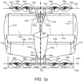
- Figures 1o and 1p illustrate a configuration of a VTOL vehicle according to the invention whilst Figures 1a-n , 2a-e , 3a-d , 4a-e , 5a-d , 6a-c and 7 illustrate example VTOL vehicles not in accordance with the claimed invention but which comprise additional features which are useful for understanding the invention and/or some of which can be used in combination with the configuration of the VTOL vehicle according to the invention. More in particular:
- the inventors propose a hybrid VTOL vehicle or aircraft that is configured to transition from a vertical take-off into a horizontal mode of flight or from a horizontal mode of flight to a vertical landing using pivotally mounted engine modules mounted on or coupled to the lifting surfaces and/or fuselage of the vehicle, where the lifting surfaces provide the primary lift when the VTOL vehicle is in the horizontal mode of flight.
- This may be achieved by the VTOL vehicle having a first lifting surface including two wings (or aerofoils) respectively secured to opposite sides of a rear section of a fuselage of the VTOL vehicle, a second lifting surface including two wings (or aerofoils) respectively secured to opposite sides of a front section of the fuselage.
- each wing may include at least one engine module, which provides thrust when the VTOL vehicle is in operation, where each engine module is pivotally coupled or mounted to the wing.
- the engine modules may each be independently controlled for transitioning the VTOL vehicle between a vertical mode of flight and a horizontal mode of flight and for controlling the orientation and flight or flight path of the VTOL vehicle.
- groups of engine modules on each wing of a lifting surface may be controlled independent of a group of engine modules on another wing of a lifting surface for transitioning the VTOL vehicle between a vertical mode of flight and a horizontal mode of flight and for controlling the orientation and flight/flight path of the VTOL vehicle.
- each group corresponding to each wing of a lifting surface, in which each engine module of a group may be controlled independent of a group of engine modules corresponding to another wing of a lifting surface for transitioning the VTOL vehicle between a vertical mode of flight and a horizontal mode of flight and for controlling the orientation and flight/flight path of the VTOL vehicle.
- the VTOL vehicle may have one or more combinations of engine modules pivotally mounted and/or coupled to sections of the fuselage of the VTOL vehicle, where each engine module is independently controllable/pivotable about a tilting axis for transitioning the VTOL vehicle between a vertical mode of flight and a horizontal mode of flight and for controlling the orientation and flight/flight path of the VTOL vehicle.
- the wings of the VTOL vehicle may be configured to have no moving flight control surfaces such as, by way of example only but not limited to, ailerons, rudders, elevators and the like that are common on most aircraft and/or helicopters and other conventional VTOL aircraft. Rather, the VTOL vehicle may be controlled only by the pivotable or tiltable engine modules, which provide thrust. For example, each engine module may be independently controlled and/or groups of engine modules on each wing of the VTOL vehicle may be independently controlled.
- the VTOL vehicle may be configured as the application demands to be based on, by way of example only but is not limited to, at least one from the group of: a fully autonomous VTOL vehicle, a remote controlled VTOL vehicle, semi-autonomous VTOL vehicle with optional interfaces for a pilot or for remote control, and/or a VTOL vehicle with control interfaces allowing manual piloting; and/or any combination thereof as the application demands.
- the VTOL vehicle may have a complete absence of aerodynamic control surfaces such as, by way of example only but not limited to, ailerons, rudders and/or elevators, in which the VTOL vehicle is controlled using the engine modules through, by way of example only but is not limited to, a combination of varying motor RPM or blade pitch and the resulting torque differentials acting on the motors and creating a change in in orientation/flight direction of the vehicle, and tilting of the rotors to create thrust vectors that change the orientation/flight direction of the vehicle
- the VTOL vehicle according to the invention has numerous advantages over other land vehicles and/or other conventional VTOL aircraft (e.g. helicopters and conventional UAVs). For example, compared with land vehicles, the VTOL vehicle can travel at a faster speed at a comparable cost to land transport, whilst avoiding the required infrastructure and cost penalties of other conventional VTOL aircraft (e.g. helicopters or UAVs). The VTOL vehicle also has improved accessibility to remote and/or off-shore locations. The VTOL vehicle provides further advantages over conventional VTOL aircraft such as, by way of example only but not limited to, helicopters.
- helicopters helicopters and conventional UAVs
- the VTOL vehicle compared to helicopters and other light aircraft, provides similar cargo and passenger lifting and transport capabilities at a reduced complexity, lower cost, better manoeuvrability, lower noise footprint, driverless (no pilot) when operating autonomously, less stringent infrastructure requirements smaller footprint.
- the VTOL vehicle according to the invention has the capability to travel at higher speeds with lower power consumption, which in effect increases the range and provides better accessibility compared to other VTOL due to compactness.
- the lifting surfaces of the VTOL vehicle may be joined or coupled together via stabilisers and/or pylons based on a box-wing or staggered double-decker configuration, which provides the advantage of improved aerodynamic efficiency, stability, structural integrity and control as compared with conventional aircraft and/or other VTOL aircraft with a single lifting surface.
- the VTOL vehicle may be an electric powered autonomous or semi-autonomous aerial vehicle with VTOL capabilities for cargo and passenger transport.
- Each engine module of the VTOL vehicle according to the invention may include, by way of example only but is not limited to, one or more from the group of: an electric ducted fan; electric ducted rotor; electric fan; electric rotor; electric jet engines; or any other power plant/thrust mechanism configurable for transitioning the VTOL vehicle between the vertical mode of flight and the horizontal mode of flight.
- the engine module(s) of the VTOL vehicle may be connected to an electrical power system, which may be powered by means of power storage devices or other electrical sources.
- electrical sources for providing electrical power to the engine modules may include, by way of example only but is not limited to, one or more or a combination of: one or more electrical storage device(s); one or more battery(ies); one or more capacitor(s); one or more solar panel(s); one or more fuel cell(s); one or more internal combustion engine(s); one or more gas turbine(s); and/or combination(s) thereof.
- the power storage devices may be exchanged or recharged on the ground or in the air via remote electrical power transmission.
- the engine modules may be powered by one or more batteries or a bank of batteries, or in a hybrid configuration including batteries and/or internal combustion engine and the like.
- the electrical source may be an electrical storage device or bank of batteries that may be charged from an external electrical power transmission grid prior to the VTOL vehicle being used; once used, the VTOL vehicle may be recharged via the electricity grid or the used batteries and/or power storage devices exchanged for charged batteries/power storage devices.
- the generation of electrical power may be based on internal combustion engines or gas turbines, which may be used to charge a bank of batteries and/or provide electric power directly to the engine modules as the need arises.
- the VTOL vehicle may include, by way of example only but is not limited to, one or more sensors for use in autonomous control, semi-autonomous/remote control, and/or providing assistance to a pilot or remote controller.
- a sensor may comprise or represent any type of device, module, equipment, or subsystem capable of detecting events or changes in its environment and providing information to other electronics or devices such as, by way of example only, a computing device, processor or system. Sensors may provide data for assisting with the control and operation of the VTOL vehicle when operating autonomously, semi-autonomously, remote controlled, and/or piloted by a human operator.
- sensors may include, by way of example only but is not limited to, one or more of accelerometer(s); gyroscope(s); range sensor(s) for estimating distance to obstacles (e.g. stereoscopic cameras, light detection and ranging (LIDAR), sonar, radar, ultrasound sensors, and the like); altimeters (barometric devices); computer vision systems; relative motion sensor(s) for detecting position and motion relative to ground or other objects (e.g. visual camera); magnetometers; global positioning system (GPS) sensors or receivers; speed sensors; level sensors; airspeed sensors; position control means using electromagnetic waves between vehicle and ground stations (e.g. radio or telecommunications systems); temperature sensors; infra-red sensors; night vision sensors and the like; weather radar; and/or any other sensor or sensor equipment suitable for assisting the control and/or operation of the VTOL vehicle during operation.
- GPS global positioning system
- the communication connection may be encrypted and be configured to provide protection from jamming.
- the VTOL vehicle may use one or more communication interfaces based on, by way of example only but is not limited to, one or more of a) a radio link; b) an LTE mobile interface; c) a 5G mobile interface; and d) a satellite interface; or any other communication interface depending on the application.
- These communication interfaces may be configured to have a medium level of encryption and protection from jamming and will offer various ranges of coverage depending on the application.
- the communication interfaces b) c) and d) may be encrypted within a virtual private network. Control and monitoring the status of the VTOL vehicle may be through a secure cloud network based application, subject to regulatory requirements.
- communication interfaces b) and c) can offer a larger range than communication interface a). Furthermore, communication interfaces b) and c) provide an improved secure solution with typically increased bandwidth compared with a radio link, but may have a relatively higher cost due to mobile operator charges.
- Communication interface d) e.g. satellite
- satellites can be an expensive solution in terms of cost, but is useful for extreme remote locations or off-shore locations where range is of importance and/or locations out of range of communication interfaces a), b) and c).
- the VTOL vehicle provides fully vertical take-off and landing capabilities in which the VTOL vehicle may take-off and land on any location depending on the dimensions of the VTOL vehicle.
- Take-off and landing may be from, by way of example only but is not limited to, footpaths, driveways, roads, helipads, runways, water such as lakes or the sea, platforms, off-shore platforms such as, by way of example only but is not limited to, ships and/or oil/gas platforms.
- the VTOL vehicle according to the invention reduces the need or requires no special infrastructure such as, by way of example only but is not limited to, helipads, winches, catapults, or runways unlike other conventional VTOL vehicles.
- the VTOL vehicle provides the advantages of a stable and controlled flight throughout all phases of a flight mission from, by way of example only but not limited to, take-off, hover, flight from a first location to a second location, final approach, hover and landing.
- the VTOL vehicle may also include several layers of redundancy of hardware and/or software for increased safety.
- the VTOL vehicle may provide an economical operation relative to alternative designs and modes of transport such as, by way of example only but not limited to, helicopters and/or other VTOL aircraft.
- the VTOL vehicle according to the invention provides an efficient mode of transport giving superior performance in terms of, by way of example only but is not limited to, range, speed, and/or payload when compared to other equivalently sized or dimensioned conventional VTOL vehicles and/or UAVs such as, by way of example only but not limited to, drones, multicopter and other conventional drone or UAV designs.
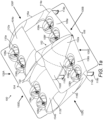
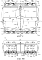
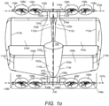
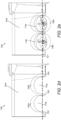
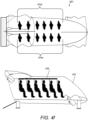
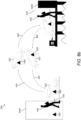
- Figure 1a is a schematic diagram illustrating a perspective view from the front of an example VTOL vehicle or aircraft 100.
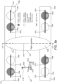
- Figure 1b is a schematic diagram illustrating a plan view 100A of the example VTOL vehicle 100 of figure 1a as viewed from arrow 100A in figure 1a .
- Figure 1c is a schematic diagram illustrating a front view 100B of the example VTOL vehicle 100 of figure 1a as viewed from arrow 100B in figure 1a .
- Figure 1d is a schematic diagram illustrating a side view 100C of the example VTOL vehicle 100 of figure 1a as viewed from arrow 100C of figure 1a .
- the VTOL vehicle 100 includes a fuselage 102 having longitudinally a front section 102a and a rear section 102b.
- the front section 102a and rear section 102b of the fuselage may have, by way of example only but is not limited to, a central section 102c there between.
- the plan view 100B of figure 1b illustrates a longitudinal axis 103 of the fuselage 102.
- the VTOL vehicle 100 has a first lifting surface 104 and a second lifting surface 106.
- the first lifting surface 104 is coupled to at least a portion of the rear section 102b of the fuselage 102.
- the second lifting surface is coupled to at least a portion of the front section 102a of the fuselage 102.
- each of the wings 104a-106b of the lifting surfaces 104 and 106 have at least one wing chord that is substantially parallel to a longitudinal axis 103 of the fuselage 102 as shown in figure 1b ; usually wing chords are parallel to the flight direction and in effect with the longitudinal axis 103 of the fuselage 102. Generally the flight direction is parallel to the longitudinal axis 103.
- the wings 104a-106b of the lifting surfaces 104 and 106 may be oriented and secured to the fuselage 102 such that a first plane parallel to the longitudinal axis 103 of the fuselage 102, where the first plane intersects a first point of wing-tip 112a of wing 104a and also intersects a corresponding (or mirrored) second point of wing-tip 112b of wing 104b, is parallel to a second plane, where the second plane is also parallel to the longitudinal axis 103 of the fuselage 102 and intersects a first point of wing-tip 114a of wing 106a and also intersects a corresponding (or mirrored) second point of wing-tip 114b of wing 106b.
- the wings 104a-104b and wings 106a-106b of the example VTOL vehicle 100 have, by way of example only but is not limited to, no dihedral angle
- the wings 106a-106b of the second lifting surface 106 may have a dihedral angle that may increase the aerodynamic stability around the roll axis, or around the longitudinal axis 103 of the fuselage.
- the wings 104a-104b of the first lifting surface 104 may also have a dihedral angle that may further increase the aerodynamic stability around the roll axis, or around the longitudinal axis 103 of the fuselage 102.
- either the wings 104a-104b and/or the wings 106a-106b may be configured to have an anhedral angle.
- wing configurations such as, by way of example only but not limited to, flat wing, dihedral angled wing, anhedral angled wing, polyhedral wing, gull wing, inverted gull wing, upward cranked tips, downward cranked tips and any other wing configuration and/or combinations thereof, modifications thereof, and/or as desired as the application demands.
- the wings 104a-104b of the VTOL vehicle 100 form a rectangular shaped wing planform when viewed from arrow 100A of figure 1a and illustrated in figure 1b . Furthermore, the wings 106a-106b of the VTOL vehicle 100 form a slight cropped delta shaped wing planform when viewed from arrow 100A of figure 1a and illustrated in figure 1b .
- the delta shape planform of wings 106a-106b may increase the aerodynamic stability around yaw axis and pitch axis of the VTOL vehicle 100.
- the wings 104a-104b and the wings 106a-106b have, by way of example but is not limited to, the above-mentioned shaped planforms, it is to be appreciated by the skilled person that the wings 104a-104b and the wings 106a-106b are not so limited and that other shaped planforms may be applied and used without loss of generality and as the application demands.
- the wings 104a-104b and the wings 106a-106b of the VTOL vehicle 100 both have a straight wing sweep when viewed from arrow 100A of figure 1a and illustrated in figure 100b.
- the wings 104a-104b and the wings 106a-106b of the VTOL vehicle 100 both have, by way of example only but are not limited to, a straight wing sweep, it is to be appreciated by the skilled person that wings 104a-104b and/or the wings 106a-106b may be configured to have other or different types of wing sweeps such as, by way of example only but not limited to, one or more or combinations of straight, swept back, or forward swept or any other type of wing sweep as the application demands.
- Each of the two wings 104a and 104b of the first lifting surface 104 further includes at least one engine module 108a and 108d pivotally mounted or coupled to wings 104a and 104b, respectively.
- wing 104a of the first lifting surface 104 has two engine modules 108a and 108b pivotally mounted to wing 104a.
- Wing 104b of the first lifting surface also has two engine modules 108c and 108d pivotally mounted to wing 104b.
- each of the two wings 106a and 106b of the second lifting surface 106 further includes at least one engine module 108e and 108h pivotally mounted or coupled to wings 106a and 106b, respectively.
- wing 106a of the second lifting surface 106 has two engine modules 108e and 108f pivotally mounted to wing 106a.
- Wing 106b of the second lifting surface also has two engine modules 108g and 108h pivotally mounted to wing 106b.
- each wing of the VTOL vehicle 100 may include at least one engine module, or two or more engine modules, or a plurality of engine modules on each wing of the VTOL vehicle 100 as the application demands.
- each engine module of the plurality of engine modules on each set of wings 104a-104b or each set of wings 106a-106b may have unequal or differently sized thrust capabilities as the application demands.
- the skilled person would appreciate that the control of the VTOL vehicle 100 may be adapted accordingly to take into account engine modules having unequal or differently sized thrust capabilities as the application demands.
- each of the engine modules 108a-108h may include, by way of example only but is not limited to, at least one from the group of: an electric ducted fan; electric ducted rotor; electric fan; electric rotor; electric jet engines; gas turbines; internal combustion engine with fans or rotors and the like; or any other power plant configurable for transitioning the VTOL vehicle between the vertical mode of flight and the horizontal mode of flight and/or maintaining the vertical mode of flight and/or maintaining the horizontal mode of flight.
- each of the engine modules 108a-108h is based on an electric ducted rotor.
- Each of the engine modules 108a-108h may be connected to a suitable power source or electrical power system such as, by way of example only but is not limited to, one or more or a combination of: power storage devices, electrical sources for providing electrical power, one or more electrical storage device(s); one or more battery(ies); one or more capacitor(s); one or more solar panel(s); one or more fuel cell(s); one or more internal combustion engine(s); one or more gas turbine(s); any other suitable electrical power source for use in powering one or more engine modules to enable, when VTOL vehicle is in use, the engine modules to provide enough thrust or a thrust vector for the VTOL vehicle 100 to enter and/or transition from between a vertical mode of flight and/or a horizontal mode of flight; and/or combination(s) thereof.
- a suitable power source or electrical power system such as, by way of example only but is not limited to, one or more or a combination of: power storage devices, electrical sources for providing electrical power, one or more electrical storage device(s); one or more battery(ies
- the power source for each of the engine modules 108a-108h may be located on the VTOL vehicle 100 as the application demands and, if necessary, according to regulatory standards/policies.
- the power source(s) for the engine modules 108a-108h may be located, by way of example only but is not limited to, within the wings 104a-106b, fuselage 102, in base 102d of the fuselage 102 and/or any other suitable location on the VTOL vehicle 100.
- Each of the engine modules 108a-108h are pivotally mounted to a corresponding one of the wings 104a-106b and pivots around a tilting axis 107a or 107b perpendicular to a longitudinal axis 103 of the fuselage 102 as illustrated in figures 1b and 1c . As illustrated in figure 1b or f , the tilting axes 107a and 107b are also substantially parallel to the plan view 110A of the VTOL vehicle 100.
- tilting axis 107a or 107b for each engine module is described, by way of example only but is not limited to, being substantially parallel to the plan view 110A of VTOL vehicle 100, it is to be appreciated by the skilled person that the tilting axis for one or more of the engine modules 108a-108h may be in line with the wing plane of the wing 104a-106b the one or more engine modules 108a-108h are pivotally mounted and/or any other suitable orientation or plane as the application demands.
- each of the engine modules 108a-108h may be oriented such that the tilting axis 107a or 107b of each of the engine modules 108a-108h is substantially perpendicular to a wing chord line of the corresponding wing 104a-106b located in the vicinity of each of the engine modules 108a-108h are pivotally mounted.
- the wing chord or chord of a wing may be determined by measuring the distance between the leading edge and trailing edge of the wing in the direction of the airflow or expected airflow over the wing.
- the wing chord line may be an imaginary line drawn from a particular location on the leading edge towards the trailing edge of the wing in the direction of airflow or expected airflow over the wing.
- each of the engine modules 108a-108h includes at least one rotor comprising at least two rotor blades coupled to a drive shaft which is driven, by way of example only but is not limited to, an electric motor.
- the drive shaft/electric motor of each of the engine modules 108a-108h may be considered the centre of the engine module.
- Each of the engine modules 108a-108h may be oriented such that the tilting axis 107a or 107b of each of the engine modules 108a-108h is perpendicular to a wing chord line that passes through the centre of the corresponding one of the engine modules 108a-108h.
- a first set of engine modules 108a-108d of the first lifting surface pivot around tilting axis 107a.
- a second set of engine modules 108e-108h of the second lifting surface pivot around tilting axis 107b.
- this example illustrates the tilting axis 107a for each engine module in the set of engine modules 108a-108d is shown to be, by way of example only but is not limited to, the same tilting axis 107a, it is to be appreciated by the skilled person that each engine module in the set of engine modules 108a-108d may be positioned to pivot around a separate or different tilting axis in which each tilting axis may be substantially perpendicular to the longitudinal axis of the fuselage but spaced apart from one or more tilting axes of one or more other engine modules of the same lifting surface.
- Each of the engine modules 108c-108d of wing 104b of the first lifting surface 104 is pivotally mounted or coupled to the wing 104b and configured to pivot around a different tilting axis that is positioned or spaced apart from the tilting axis of the other engine module 108d or 108c.
- Each of the engine modules 108a or 108b of wing 104a of the first lifting surface 104 may be coupled to a tilt mechanism including one or more actuators (not shown).
- Each tilt mechanism may be configured to pivot the engine module 108a around the corresponding tilting axis of that engine module.
- the engine modules 108a and 108b are configured to pivot around tilting axis 107a, thus one or more tilt mechanisms may be configured to tilt or pivot engine module 108a and/or engine module 108b as desired.
- each of the engine modules 108c or 108d of wing 104b of the first lifting surface 104 may be coupled to one or more tilt mechanisms (not shown).
- Each tilt mechanism may be configured to pivot the engine module 108c and/or 108d around the corresponding tilting axis 107a of that engine module.
- the engine modules 108c and 108d are configured to pivot around tilting axis 107a, thus the one or more tilt mechanisms may be configured to tilt or pivot engine module 108c and/or engine module 108d as desired.
- each of the engine modules 108e or 108f of wing 106a of the second lifting surface 106 may be coupled to one or more tilt mechanisms (not shown). Alternatively or additionally, two or more engine modules or several engine modules could also be tilted by on actuator and/or tilt mechanism. Each tilt mechanism may be configured to pivot the corresponding engine module 108e and/or 108f around the corresponding tilting axis of that engine module 108e and/or 108f. In this example, the engine modules 108e and 108f are configured to pivot around tilting axis 107b, thus one or more tilt mechanisms may be configured to tilt or pivot engine module 108e and/or engine module 108e as desired.
- each of the engine modules 108g or 108h of wing 106b of the second lifting surface 106 may be coupled to one or more other tilt mechanisms (not shown).
- Each tilt mechanism may be configured to pivot the engine module 108g or 108h around the corresponding tilting axis of that engine module 108g or 108h.
- the engine modules 108g and 108h are each configured to pivot around tilting axis 107b, thus the one or more tilt mechanisms may be configured to tilt or pivot engine module 108g and/or engine module 108h as desired.
- Each of the engine modules 108a-108h may be configured to be capable, when the VTOL vehicle 100 is in operation or use, of producing a thrust (or thrust vector) in the direction of airflow in line with a wing chord of a corresponding wing 104a-106b for maintaining or operating in the horizontal mode of flight when pivoted to at least one of the flight mode position(s).
- Each of the engine modules 108a-108h may also be configured to be capable, when the VTOL vehicle 100 is in operation or use, of producing a thrust (or thrust vector) perpendicular to a wing plane (or a plane substantially parallel to the corresponding lifting surface or wing surface) or substantially perpendicular to the wing chord when pivoted to at least one or more vertical mode positions for maintaining or operating in the vertical mode of flight (e.g. to maintain a hover or a vertical mode of flight during landing).
- a thrust or thrust vector
- each of the engine module(s) 108a-108h may be pivotable between at least a first position lying within the wing plane of the corresponding wing and at least a second position lying substantially in a plane perpendicular to the wing plane, where each of the engine module(s) 108a-108h is capable of producing thrust substantially perpendicular to the wing plane when in the at least one first position (e.g. a vertical mode position) and is capable of producing thrust substantially parallel to the wing plane when in the at least one second position (e.g. a flight mode position).
- first position e.g. a vertical mode position
- second position e.g. a flight mode position
- the wings 104a-106b do not provide any lifting force capable of keeping the VTOL vehicle aloft 100 when the VTOL vehicle is in a vertical mode of flight.
- the horizontal mode of flight may be defined to occur when the engine modules 108a-108h of the VTOL vehicle 100, when in use, are suitably pivoted from a vertical mode position to a flight mode position and controlled to substantially produce the required thrust necessary ensure the wings 104a-106b of the lifting surfaces 104 or 106 of the VTOL vehicle 100 substantially produce the required lifting force necessary to keep the VTOL vehicle 100 aloft or on a particular flight path and/or orientation etc.
- the VTOL vehicle 100 may transition from a vertical mode of flight to a horizontal mode of flight by controlling the change in tilt angle or pivot and also the change in thrust output from each of the engine modules 108a-108h until the wings 104a-106b of the lifting surfaces 104 and 106 have sufficient or more airflow for keep the VTOL vehicle 100 at least aloft.
- the engine modules 108a-108h During the transition from the vertical mode of flight to the horizontal mode of flight the engine modules 108a-108h, and as the engine modules 108a-108h are pivoted from one of the vertical mode positions to one of the horizontal mode positions, the engine modules 108a-108h and the lifting surfaces 104 and 106 being to share the lifting forces required to keep the VTOL vehicle 100 aloft or on a particular flight path or flight orientation.
- the engine modules 108a-108h take most of the burden of generating the required thrust to keep the VTOL vehicle 100 aloft or airborne.
- the wings 104a-106b of the lifting surfaces 104 and 106 start to generate sufficient lifting force to keep the VTOL vehicle aloft and allow the VTOL vehicle 100 to follow a flight path or orientation, with the engine modules 108a-108h only providing the necessary forward motion and/or changes in orientation, direction, position and the like.
- the engine modules 108a-108h of VTOL vehicle 100 may be configured to be independently controlled (e.g. by a flight control system or apparatus) for transitioning between the vertical mode of flight and the horizontal mode of flight. This provides the advantage of improved manoeuvrability and a smoother flight when operating the VTOL vehicle 100.
- groups of engine modules on each of the wings 104a-106b may be jointly controlled and independently controlled in relation to other groups of engine modules on other wings 104a-106b.
- each of the engine modules 108a-108h are configured to be pivotable about a tilt axes 107a and/or 107b and are mounted in the vicinity of the trailing edge of the corresponding wing 104a-106b.
- the tilt axis 107a and 107b for each engine module 108a-108h may be perpendicular to the longitudinal axis 103 of the fuselage 102 and/or a wing chord line in the vicinity of each of the corresponding engine modules 108a-108h.
- the wing chord line may passes through the centre of the corresponding engine module (e.g.
- each engine module 108a-108h when in the horizontal mode of flight, when the VTOL vehicle 100 is in operation, each engine module 108a-108h is pivoted such that the airflow over the wings 104a-106b is substantially in the direction of thrust of at least one or more of the engine modules 108a-108h.
- Each of the engine modules 108a-108h may include a tilt mechanism (not shown) configured for independently pivoting each of the engine modules 108a-108h about the tilt axis or pivot axis 107a or 107b to allow the VTOL vehicle 100 to transition from a vertical mode of flight to a horizontal mode of flight.
- the tilt mechanism (not shown) may be configured for independently pivoting said each of the engine modules 108a-108h about the tilt axis 107a or 107b of the corresponding engine module.
- the wings 104a-106b of the VTOL vehicle 100 are configured to have no moving flight control surfaces such as, by way of example only but not limited to, ailerons, rudders, elevators and the like that are common on most aircraft and/or helicopters and other conventional VTOL aircraft.
- the VTOL vehicle 100 may be controlled only by the pivotable or tiltable engine modules 108a-108h, which provide thrust, in which each of the engine modules 108a-108h may be independently controlled and/or groups of engine modules on each of the wings 104a-106b of the VTOL vehicle 100 may be independently controlled.
- two or more engine modules may be configured to be used to control the aircraft when the motors of the engine modules are not operating (e.g.
- such engine modules may be temporarily used (e.g. in an emergency due to a malfunction on two or more engine modules) as aileron(s)/rudder(s) by activating the tilt mechanisms and/or feathering the rotor blades etc.
- the VTOL vehicle 100 in which each of the engine modules 108a-108h are independently controllable provides the advantages of improved stability and manoeuvrability during the vertical modes of flight, transitioning between vertical modes of flight and horizontal modes of flight, and/or in the horizontal modes of flight.
- Grouping the engine modules 108a-108h into sets of engine modules in which each set of engine modules is controlled in unison may provide the advantage of reduced complexity and possible weight savings in relation to the reduced number of tilt mechanism, but at a cost of reduced stability and manoeuvrability when compared to a VTOL vehicle 100 in which each of the engine modules 108a-108h are independently controlled.
- the engine modules or groups of engine modules may be independently controlled as the application demands.
- the VTOL vehicle 100 may be configured as the application demands to be based on, by way of example only but is not limited to, at least one from the group of: a fully autonomous VTOL vehicle, a remote controlled VTOL vehicle, semi-autonomous VTOL vehicle with optional use and/or communication interfaces for a pilot or for remote control, and/or a VTOL vehicle with control user interfaces allowing manual piloting; and/or any combination thereof as the application demands.
- the VTOL vehicle 100 may include an on-board flight control system that may include a flight controller device (not shown) coupled to or connected to the pivotable engine modules 108a-108h.
- the flight controller device may be configured to control the pivot and thrust of each of the engine modules 108a-108h independently, and/or control the pivot and thrust of a set of engine modules of the engine modules 108a-108h in unison.
- the flight controller device may be configured to control, by way of example only but is not limited to, the motor RPM and/or tilt mechanisms of each of the engine modules 108a-108h to give the VTOL vehicle 100 the desired, by way of example only but not limited to, attitude, orientation, speed and altitude.
- the flight controller device may receive instructions to control the engine modules through inputs by a human user, or an autonomous device or a machine/autopilot either on board the VTOL vehicle 100 and/or remotely.
- the flight controller device may be configured to control, by way of example only but is not limited to, one or more of the modes of flight operation of the VTOL vehicle 100 (e.g. vertical mode of flight and/or horizontal mode of flight and transitioning there between), speed, position, direction, orientation and/or flight path of the VTOL vehicle 100 and other aspects of the VTOL vehicle 100 as the application demands.
- the modes of flight operation of the VTOL vehicle 100 e.g. vertical mode of flight and/or horizontal mode of flight and transitioning there between
- a flight control system may include the flight controller device, one or more power sources, and the engine modules 108a-108h of the VTOL vehicle, in which the flight controller device couples the power source(s) with the engine modules 108a-108h for controlling, by way of example only but not limited to, the mode of operation of the VTOL vehicle 100, flight path, position, orientation, speed and attitude of the VTOL vehicle 100 and the like.
- the flight control system may further include a user interface device (not shown) coupled to the flight controller, where the flight controller is configured for controlling one or more of the engine modules 108a-108h in response to a user position, speed or directional input from the user interface.
- the user interface device may comprise or represent any one or more devices that is configured to receive user input in relation to controlling the VTOL vehicle 100.
- Examples of user interface device may include, by way of example only but is not limited to, one or more or a combination of a touch screen device(s), keyboard(s), control panel(s), control console(s), joy stick, pedals, steering wheel and any other device allowing a user to control the flight path and/or direction, take-off and landing of the VTOL vehicle 100 and the like.
- the user interface device allows a human pilot within the VTOL vehicle 100 to pilot the VTOL vehicle with the assistance of the flight controller, which manages and controls the multiple engine modules 108a-108h to implement the desired user input received from the user interface device.
- a user of the VTOL vehicle 100 does not need to understand or know how to control, by way of example only but not limited to, the thrust, RPM, or pivot of each of the individual engine modules 108a-108h in order to pilot the VTOL vehicle 100. Rather, the user uses the user interface device to input the desired flight path, direction, orientation, speed, attitude, hover, take-off and landing and other inputs of the VTOL vehicle 100.
- the flight control system may further include an autonomous interface device coupled the flight controller.
- the autonomous interface may include or be coupled to one or more communication interfaces for communicating with a remote operations centre.
- the autonomous interface is configured for interpreting mission or session instructions/commands from the remote operations centre, and based on the mission instructions/commands to autonomously direct the flight controller device to operate the VTOL vehicle 100 in accordance with the mission instructions/commands received from the remote operations control centre.
- the mission instructions or commands may be to direct the VTOL vehicle 100, which has landed at a location A, to fly to location B to pick up a payload comprising a spare part for delivery a location C at a certain time.
- the mission instructions may include, by way of example only but not limited to, data representative of the necessary geographic, weather, and time information and other instructions or information to enable the VTOL vehicle 100 to autonomously take-off from location A, transition from a vertical mode of flight to a horizontal mode of flight and navigate to location B, transition from a horizontal mode of flight to a vertical mode of flight and land at location B for receiving the spare part and/or recharging the VTOL vehicle 100.
- the VTOL vehicle 100 may autonomously continue the mission and autonomously takes-off from location B, transitions from a vertical mode of flight to a horizontal mode of flight and navigates to location C, transitions from a horizontal mode of flight to a vertical mode of flight and lands at location C for delivering the spare part.
- the VTOL vehicle 100 may autonomously return to location A or any other location as directed by the remove operations centre.
- the payload may instead be one or more passengers that require transport from location B to location C.
- the VTOL vehicle 100 may further include a sensor suite or a set of sensor(s), which are also connected to the flight control system.
- Each of the sensor(s) provides data representative of a sensor signal for use by the flight controller to control the operation and/or flight of the VTOL vehicle 100.
- the set of sensors may provide data for assisting with the control and operation of the VTOL vehicle 100 when operating autonomously, semi-autonomously, remote controlled, and/or piloted by a human operator/user.
- Examples of sensors for use with the VTOL vehicle 100 may include, by way of example only but is not limited to, one or more of accelerometer(s); gyroscope(s); range sensor(s) for estimating distance to obstacles (e.g.
- LIDAR light detection and ranging
- radar ultrasound sensors
- altimeters computer vision systems
- relative motion sensor(s) for detecting position and motion relative to ground or other objects (e.g. visual camera); magnetometers; global positioning system (GPS) sensors or receivers; speed sensors; level sensors; airspeed sensors; position control means using electromagnetic waves between vehicle and ground stations (e.g. radio or telecommunications systems); temperature sensors; infra-red sensors; night vision sensors and the like; weather radar; and/or any other sensor or sensor equipment suitable for assisting the control and/or operation of the VTOL vehicle during operation.
- GPS global positioning system
- the flight controller may receive the a control input that may include data representative of at least one from the group of: speed, direction, orientation, position, flight and attitude in relation to the VTOL vehicle.
- the flight controller may also receive sensor data from the set of sensor(s) for assisting the flight controller in operating the VTOL vehicle 100.
- the control input may be user input data from a user interface device and/or autonomous data from an autonomous device as described herein.
- the flight controller may receive autonomous data from the autonomous control device associated with mission/operation instructions.
- the flight controller may receive user input data from a user input interface.
- the flight controller may perform a comparison of the current status of the VTOL vehicle 100 (e.g.
- the flight controller may use the comparison and the control input data, user input data, the sensor data and/or the autonomous data to, by way of example only but not limited to, control the thrust and/or pivot orientation of each of the engine modules 108a-108h independently and to change the current status (e.g. orientation and/or flight path) of the VTOL vehicle 100 towards the desired status in response to the received control input, received sensor data, received user input (if any) and/or the received autonomous data (if any).
- the flight controller device may control one or more of the engine modules 108a-108h independently based on one or more engine module operations from the group of: revolutions per minute of rotors of an engine module; rotor blade pitch of an engine module; torque differentials acting on each engine module; independently tilting or pivoting of each of the engine modules 108a-108h for generating thrust vectors for changing speed, direction or position of the VTOL vehicle; and/or any other engine module operation that may be used to control the flight path and/or orientation and the like of the VTOL vehicle 100.
- engine module operations may be used by the flight controller to adjust the VTOL vehicle 100 according to a coordinate system with respect to the VTOL vehicle 100.
- a 3-dimensional coordinate system may be defined by an x-axis, a y-axis and a z-axis.
- the x-axis is defined to be parallel to the longitudinal axis 103 of the fuselage of the VTOL vehicle 100.
- the y-axis is defined to be perpendicular to the x-axis and substantially parallel to the tilting axis of the engine modules 108a-108h and/or substantially parallel to plane or line intersecting the distal ends of the wingtips 112a-112b and/or 114a-114b of the wings 104a-104b and/or wings 106a-106b, respectively.
- the z-axis may be defined to be perpendicular to the x-axis and the y-axis. Thus, toward the wing plane with respect to the a n x-direction, y direction, z-direction.
- the flight controller may only use the above-mentioned engine module operations to control the orientation and flight of the VTOL vehicle 100.
- a certain combination of engine module operations may be used to direct the VTOL vehicle 100 along, by way of example only but not limited to, the x-axis, the y-axis, and/or the z-axis and/or direct the VTOL vehicle 100 around, by way of example only but not limited to, the x-axis (e.g. a roll ), the y-axis (e.g. a pitch or pivot), and/or around the z-axis (e.g. a yaw).
- the x-axis e.g. a roll
- the y-axis e.g
- the flight controller may be further configured to also efficiently control the rotation of the rotors of each of the engine modules 108a-108h.
- the flight controller may be configured to control the rotation of rotors of one of the engine modules 108a-108b pivotally mounted on the first wing 104a of the first lifting surface 104 in an opposite direction to any adjacent engine module on the first wing 104a of the first lifting surface 104.
- the flight controller may further control the rotation of the rotors of each of the engine modules 108c-108d on a second wing 104b of the first lifting surface 104 in an opposite direction to the rotation of rotors of a correspondingly positioned or mirror positioned engine module 108a-108b, respectively, on the first wing 104a of the lifting surface 104.
- the rotors of the engine module 108a on the first wing 104a of the first lifting surface 104 may have an opposite rotation to the engine module 108b on the first wing 104a of the first lifting surface.
- the rotors of the engine module 108d mounted on the second wing 104b of the first lifting surface 104 have an opposite rotation to the rotors of the engine module 108a mounted on the first wing 104a of the first lifting surface 104.
- These engine modules 108a and 108d are correspondingly positioned or mirror image positioned engine modules.
- the rotors of the engine module 108c mounted on the second wing 104b of the first lifting surface 104 have an opposite rotation to the rotors of the engine module 108b mounted on the first wing 104a of the first lifting surface 104.
- These engine modules 108b and 108c are correspondingly positioned or mirror image positioned engine modules.
- the flight controller may further control the rotors of each of the engine modules 108e-108h mounted of the second lifting surface 106 in an opposite rotation to the rotors of one of the correspondingly positioned engine modules 108a-108d mounted on the first lifting surface 104.
- the rotors of the engine module 108e of the second lifting surface 106 may be controlled to have an opposite rotation to the rotors of the engine module 108a of the first lifting surface 104.
- the rotors of the engine module 108f of the second lifting surface 106 may be controlled to have an opposite rotation to the rotors of the engine module 108b of the first lifting surface 104.
- the rotors of the engine module 108g of the second lifting surface 106 may be controlled to have an opposite rotation to the rotors of the engine module 108c of the first lifting surface 104.
- the rotors of the engine module 108h of the second lifting surface 106 may be controlled to have an opposite rotation to the rotors of the engine module 108d of the first lifting surface 104. This enhances the efficiency and stability of the VTOL vehicle 100 when in vertical mode of flight, when transitioning between a vertical mode of flight and a horizontal mode of flight, and when in a horizontal mode of flight.
- the flight system of the VTOL vehicle 100 may be implemented as one or more apparatus or computing devices, in which each apparatus and/or each computing device may include a processor unit, a memory unit and/or a communication interface, the processor unit connected to the memory unit and/or the communication interface.
- the memory unit may include a computer-readable medium with data or instruction code, which when executed on the processor unit, causes the processor unit to implement the functionality of the flight controller as described herein and/or modifications thereof.
- the apparatus or computing device may be further configured to implement the functionality of the autonomous device, the user interface and/or the sensor suite or interface with the sensor suite as described herein and/or modifications thereof.
- the wings 104a-104b and 106a-106b of the first lifting surface 104 and second lifting surface 106 respectively, each provide an amount of lift when the VTOL vehicle 100 is in the horizontal mode of flight that is dependent on the centre of gravity of the VTOL vehicle 100 and centre of lift of generated by the engine modules 108a-108d of the first lifting surface 104 and the engine modules 108e-108h of the second lifting surface 106.
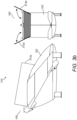
- the wings 104a-104b and 106a-106b of the first and second lifting surfaces 104 and 106 respectively, have cut-outs 110a-110h in the vicinity of the trailing edges of the wings 104a-106b for receiving one of the engine modules 108a-108h.
- Each engine module being mounted to a corresponding wing 104a-106b and pivotable along a tilting axis 107a or 107b that is perpendicular to the longitudinal axis 103 of the fuselage 102.
- the positioning of the engine modules 108a-108h in the vicinity of the trailing edges of the wings 104a-106b of VTOL vehicle 100 means that the centre of gravity of the VTOL vehicle 100 is located in a way to maximise thrust and ensure safe operation from the motors of the engine modules 108a-108h during take-off, hover and landing. This impacts the required lift generated from the wings 104a-106b since the centre of lift of the wings 104a-106b is not co-located with the centre of lift of the motors of the engine modules 108a-108h.
- each engine module is mounted to a corresponding wing 104a-106b in the vicinity of, by way of example only but is not limited to, the trailing edge of the corresponding wing 104a-106b
- one or more of the engine modules 108a-108h may be mounted in the vicinity of other portions or parts of the structure of the corresponding wing 104a-106b such as, by way of example only but not limited to, in the vicinity of the leading edge of the corresponding wing 104a-106b, in the vicinity of the middle of the corresponding wing 104a-106b, and/or mounted to any other position or location of the corresponding wing 104a-106b or as the application demands.
- one or more further engine modules may be pivotally mounted by pylons or struts to the fuselage 102 of the VTOL vehicle. These further engine modules may be static and/or retractable into the fuselage 102 of the VTOL vehicle. If retractable, then these further engine modules may be used for vertical modes of flight, hovering and/or transitioning between vertical to horizontal modes of flight, and/or only in take-off and/or landing operations, and/or where additional thrust may be required.
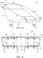
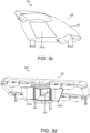
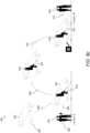
- FIG. 1g is a schematic diagram illustrating a perspective view from the front of another example VTOL vehicle or aircraft 130 and which is based on VTOL vehicle or aircraft 100 of figures 1a-1f .
- Figure 1h is a schematic diagram illustrating a plan view 130A of the example VTOL vehicle 130 of figure 1g as viewed from arrow 130A in figure 1g .
- Figure 1i is a schematic diagram illustrating a front view 130B of the example VTOL vehicle 130 of figure 1g as viewed from arrow 130B in figure 1g .
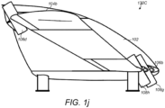
- Figure 1j is a schematic diagram illustrating a side view 130C of the example VTOL vehicle 130 of figure 1g as viewed from arrow 130C of figure 1g .
- the VTOL vehicle 130 is based on the VTOL vehicle 100 of figures 1a-1f in which the positioning or mounting of the engine modules 108e-108h has been modified.
- the wings 104a-104b and 106a-106b of the first lifting surface 104 and second lifting surface 106, respectively, each provide an amount of lift when the VTOL vehicle 130 is in the horizontal mode of flight that is dependent on the centre of gravity of the VTOL vehicle 130 and centre of lift of generated by the engine modules 108a-108d of the first lifting surface 104 and the engine modules 108e-108h of the second lifting surface 106.
- the wings 104a-104b and 106a-106b of the first and second lifting surfaces 104 and 106 respectively, have cut-outs 110a-110h in the vicinity of the trailing and leading edges of the wings 104a-106b for receiving one of the engine modules 108a-108h.
- the wings 104a-104b of the first lifting surface 104 has cut-outs 110a-110d in the vicinity of the trailing edge the wings 104a-104b for receiving one of the engine modules 108a-108d.
- each of the wings 104a-104b of the first lifting surface 104 has cut-outs 110a-110d along the trailing edge of the corresponding wing 104a-104b, each cut-out 110a-110d configured for receiving a corresponding engine module pivotable about a first tilting axis 107a, which is substantially perpendicular to the longitudinal axis 103 of the fuselage 102.
- Each of the engine modules 108a-108d is mounted to a corresponding wing 104a-104b and pivotable about or around the first tilting axis 107a that is perpendicular to the longitudinal axis 103 of the fuselage 102.
- the VTOL vehicle 130 has been modified from VTOL vehicle 100 of figures 1a-1f in which the wings 106a-106b of the second lifting surface 106 has cut-outs 110e-110h in the vicinity of the leading edge the wings 106a-106b for receiving one of the engine modules 108e-108h. That is, each of the wings 106a-106b of the second lifting surface 106 have cut-outs 110e-110h along the leading edge of the wing 106, each cut-out 110e-110h configured for receiving an engine module pivotable about second or third tilting axes 107b or 107c, which are substantially perpendicular to the longitudinal axis of the fuselage.
- Each of the engine modules 108e-108h being mounted to a corresponding wing 104a-106b and pivotable about or around the second or the third tilting axis 107b or 107c that are perpendicular to the longitudinal axis 103 of the fuselage 102.
- a first pair of engine modules 108e and 108h from wings 106a and 106b, respectively, are positioned to pivot around the second tilting axis 107b.
- a second pair of engine modules 108f and 108g from wings 106a and 106b, respectively, are positioned to pivot around the third tilting axis 107c.
- the second and third tilting axes 107b and 107c are separate or different tilting axes that may be substantially perpendicular to the longitudinal axis 103 of the fuselage 102 but are spaced apart from each other due to the sweep of the leading edge of wings 106a and 106b.
- each tilting axis may be a tilting axis for at least a pair of engine modules from each wing 106a and 106b.
- Each of the engine modules 108a-108h may include a plurality of rotors or thrust mechanisms supported about a centre axis of the engine module, where the centre axis is substantially perpendicular to the tilting axis.
- the plurality of rotors or thrust mechanism may be configured to provide a thrust, when in operation, that is in a direction substantially perpendicular to the corresponding tilting axes 107a-107c of the corresponding engine module.
- each of the engine modules 108a-108h may provide a thrust that is in a direction substantially perpendicular to the corresponding tilting axis 107a-107c of that engine module.
- each of the engine modules 108a-108h of wings 104a-106b may be coupled to a tilt mechanism including one or more actuators (not shown) in which each tilt mechanism may be configured to independently pivot each of the engine modules 108a-108h around the corresponding tilting axes 107a-107c corresponding to that engine module.
- the engine modules 108a-108h of the VTOL vehicle 130 are thus configured for transitioning the VTOL vehicle 130 between a vertical mode of flight and a horizontal mode of flight.
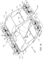
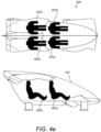
- Figure 1k is a schematic diagram illustrating a perspective view from the front of an further example VTOL vehicle or aircraft 140 which is based on VTOL vehicle or aircraft 100 of figures 1a-1f or VTOL vehicle or aircraft 130 of figures 1g to 1j .
- Figure 1l is a schematic diagram illustrating a plan view 140A of the example VTOL vehicle 140 of figure 1k as viewed from arrow 140A in figure 1k .
- Figure 1m is a schematic diagram illustrating a front view 140B of the example VTOL vehicle 140 of figure 1k as viewed from arrow 140B in figure 1k .
- Figure 1n is a schematic diagram illustrating a side view 140C of the example VTOL vehicle 140 of figure 1k as viewed from arrow 140C of figure 1k .
- the VTOL vehicle 140 is based on the VTOL vehicle 100 of figures 1a-1f or the VTOL vehicle 130 of figures 1g to 1j in which the positioning or mounting of the engine modules 108a-108h has been modified.
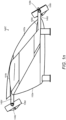
- the VTOL vehicle 140 is based on VTOL vehicle 100 of figures 1a-1f or the VTOL vehicle 130 of figures 1g to 1j but has been modified such that each of the engine modules 108a-108h are pivotally mounted to one or more tilting mechanisms 144a-144b and/or 148a-148b coupled to supporting struts 142a-142d and 146a-146d that are attached to the corresponding wing 104a-106b of VTOL vehicle 140 and/or portions of the fuselage 102.
- the tilting mechanisms 144a-144b and/or 148a-148b may be configured to independently pivot or tilt each of the engine modules 108a-108h for a vertical mode of flight (e.g.
- VTOL vehicle 140 transitioning between vertical to a horizontal mode of flight, and in a horizontal mode of flight of VTOL vehicle 140 as described with reference to VTOL vehicle 100 of figures 1a-1f , VTOL vehicle 130 of figures 1g to 1j , and/or as herein described.
- each of the wings 104a-104b of the first lifting surface 104 have at least one support strut 142a-142d mounted or connected along the trailing edge of the wing 104 and/or connected to a rear portion of the fuselage 102.
- there are four support struts 142a-142d it is to be appreciated by the skilled person that any number of one or more support struts may be used to support the tilt mechanism(s) 144a and 144b and also corresponding engine modules and/or as the application demands.
- support struts 142a and 142d may be optional, and so the tilt mechanisms 144a and 144b may be supported only by support struts 142b and 142c, respectively.
- the support struts 142b and 142c may be combined to form a single support strut for supporting tilt mechanisms 144a and 144b and corresponding engine modules 108a-108d.
- each support strut 142a-142d is configured for supporting first tilt mechanism(s) 144a and 144b to which engine modules 108a-108d are pivotally coupled/connected/mounted.
- the first tilt mechanism(s) 144a-144b are configured to control the pivoting of each of the engine modules 108a-108d so that they are pivotable about a tilting axis 107a that is substantially perpendicular to the longitudinal axis 103 of the fuselage 102.
- the first tilt mechanism(s) 144a and 144b may be configured to independently control or pivot each of the engine modules 108a-108d about the tilting axis 107a.
- the support struts 142a-142d may be configured and mounted to the trailing edge of wings 104a-104b such that each of the corresponding engine modules 108a-108d have enough clearance from the trailing edge of the wings 104a-104b to enable the first tilt mechanism(s) 144a-144b to pivot each of the engine modules 108a-108d from at least a first pivot position corresponding to a vertical mode of flight of VTOL vehicle 130 to at least a second pivot position corresponding to a horizontal mode of flight of the VTOL vehicle 140.
- the additional support struts 142a and 142d may provide the advantages, for box wing aircraft, of additional support and rigidity to the wings and also additional support and rigidity to the tilt mechanism 144a-144b.
- a first set of support struts 142a-142b are mounted to the trailing edge of wing 104a of the first lifting surface 104 in which a first support strut 142a is mounted to the trailing edge of wing 104a in the vicinity of wing-tip 112a and a second support strut 142b is mounted to the trailing edge of wing 104a in the vicinity of the end 112c of wing 104a that is secured to a portion 102b of the fuselage 102.
- a first tilting mechanism section 144a of the first tilting mechanism(s) 144a-144b is mounted or coupled to the first set of support struts 142a-142b.
- the tilting mechanism section 144a is configured to pivot the engine modules 108a-108b when required.
- the tilting mechanism section 144a may be configured to independently pivot each of the engine modules 108a-108b as the application demands.
- a second set of support struts 142c-142d are mounted to the trailing edge of wing 104b of the first lifting surface 104 in which a third support strut 142d is mounted to the trailing edge of wing 104b in the vicinity of wing-tip 112b and a fourth support strut 142c is mounted to the trailing edge of wing 104b in the vicinity of the end 112d of wing 104b that is secured to a portion 102b of the fuselage 102.
- a second tilting mechanism section 144b of the first tilting mechanism(s) 144a-144b is mounted or coupled to the second set of support struts 142c-142d.
- the second tilting mechanism section 144b is configured to pivot the engine modules 108c-108d when required.
- the second tilting mechanism section 144b may be configured to independently pivot each of the engine modules 108c-108d as the application demands.
- the tilting mechanisms 144a-144b are configured to enable the engine modules 108a-108d to be coupled to the wings 104a and 104b and to be independently tiltable or pivotable around tilting axis 107a.
- Tilt mechanism 144a and 144b may form one piece or one tilt mechanism in which the tilt mechanism is configured to enable or control the corresponding engine modules 108a-108d to rotate or pivot independently about tilt axis 107a.
- the tilt mechanism 144a and 144b may attach to the fuselage 102 or to a rear region of the rear section 102b of the fuselage 102, and/or in the vicinity of the rear section 102b and trailing edge of wings 104a and 104b.
- An example of the tilting mechanisms 144a-144b may include, by way of example only but is not limited to, a number of independently tiltable rods, one tiltable rod coupled to each engine module 108a-108d. Each tiltable rod may be configured to pivot or tilt the corresponding engine module around or about the tiltable axis 107a. Additionally or alternatively, the tilting mechanisms 144a-144b may include static tilt rods, each static tilt rod coupled via a tilt actuator or apparatus (not shown) to an engine module, where each actual tilt actuator or apparatus that is coupled to an engine module is configured to control pivoting/tilting of the engine module relative to the static tilt rod about tilt axis 107a.
- the VTOL vehicle 140 is illustrated in figures 1k to 1n as having, by way of example only but is not limited to, four engine modules 108a-108d connected to tilting mechanisms 144a-144b that are coupled to the wings 104a and 104b by struts 142a-142d.
- the tilting mechanisms 144a-144b may include an independently tiltable rod for each of the engine modules 108a-108d.
- the tilting rods may be coaxial, coaxially located or located next to each other.
- the tilting mechanisms 144a-144b may include four independently tiltable rods, e.g. one tiltable rod for each engine module 108a-108d.
- the tilting mechanisms 144a-144b may include a first tiltable section 144a that is coupled to wing 104a by struts 142a-142b and a second tiltable section 144b that is coupled to wing 104b by struts 142c-142d.
- the first tiltable section 144a is associated with wing 104a and may include independent tiltable rods for each engine module 108a-108b associated with wing 104a.
- the second tiltable section 144b is associated with wing 104b and may include independent tiltable rods for each engine module 108c-108d associated with wing 104b.
- the tilting mechanism(s) 144a-144b are connected to the rear of wing 104 of the VTOL vehicle 140.
- the tilting mechanism(s) 144a-144b may be connected via one or more support struts to a rear section of the fuselage 102.
- the tilt mechanism(s) 144a-144b may be based on static tilt rods in which each static tilt rod is associated with a corresponding engine module and an actual tilt actuator, in which the tilt actuator is mounted/attached or coupled between the static tilt rod and the corresponding engine module.
- the tilt actuator of the static tilt rod is configured or controlled to tilt/pivot the corresponding engine module about the tilt axis 107a.
- Each of the corresponding engine modules 108a-108d may be tilted relative to each of corresponding static tilt rods about the tilt axis 107a.
- each tilting rod has been described, by way of example only but is not limited to, corresponding to pivoting or being pivotally coupled to one engine module, it is to be appreciated by the skilled person that each tilting rod may include engine units (not shown) that include multiple engine modules connected together, in which the engine units are coupled to the tilting rod and pivotable around the tilting axis 107a. That is each tiltable rod may include a set of multiple engine modules coupled thereto, in which each set of engine modules is pivotable around the tilting axis 107a as the tilting rod rotates.
- a set of multiple engine modules may be coupled to each static tilt rod via a set of corresponding tilt actuators, with each tilt actuator in the set of tilt actuators being spaced between each engine module of the set of multiple engine modules.
- Each tilt actuator may be configured to independently pivot each of the engine modules in the set of multiple engine modules.
- tilting mechanisms 144a and 144b are illustrated and described as being located or mechanically coupled to, by way of example only but is not limited to, struts 142a-142d, it is to be appreciated by the skilled person in the art that the tilting mechanisms 144a and 144b may be collocated with the trailing edges of the rear wings 104a-104b and/or mounted to the rear section of the fuselage 102 of the VTOL vehicle.
- this may also include or require cut-outs for allowing engine modules 108a-108d to pivot about the tilting axis 107a from a first pivot position corresponding to a vertical mode of flight to a second pivot position corresponding to a horizontal model of flight.
- each of the wings 106a-106b of the second lifting surface 106 have at least one support strut 146a-146d mounted or connected along the leading edge of the wing 106 and/or fuselage 102.
- there are four support struts 146a-146d it is to be appreciated by the skilled person that any number of one or more support struts may be used to support the tilt mechanism(s) 148a and 148b and also corresponding engine modules and/or as the application demands.
- support struts 146a and 146d may be optional, and so the tilt mechanisms 148a and 148b may be supported only by support struts 146b and 146c, respectively.
- the support struts 146b and 146c may be further combined to form a single support strut for supporting tilt mechanisms 148a and 148b and corresponding engine modules 108e-108h.
- each support strut 146a-146d is configured for supporting second tilt mechanism(s) 148a and 148b to which engine modules 108e-108h are pivotally coupled/connected/mounted.
- the second tilt mechanism(s) 148a-148b are configured to control the pivoting of each of the engine modules 108e-108h so that they are pivotable about a tilting axis 107b that is substantially perpendicular to the longitudinal axis 103 of the fuselage 102.
- the second tilt mechanism(s) 148a and 148b may be configured to independently control or pivot each of the engine modules 108e-108h about the tilting axis 107b.
- the support struts 146a-146d may be configured and mounted to the leading edge of wings 106a-106b such that each of the corresponding engine modules 108e-108h have enough clearance from the leading edge of the wings 106a-106b to enable the second tilt mechanism(s) 148a-148b to pivot each of the engine modules 108e-108h from at least a first pivot position corresponding to a vertical mode of flight of VTOL vehicle 130 to at least a second pivot position corresponding to a horizontal mode of flight of the VTOL vehicle 140.
- the additional support struts 146a and 146d may provide the advantages, for box wing aircraft, of additional support and rigidity to the wings 106a and 106b and also additional support and rigidity to the tilt mechanism 148a-148b.
- a third set of support struts 146a-146b are mounted to the leading edge of wing 106a of the second lifting surface 106 in which a first support strut 146a is mounted to the leading edge of wing 106a in the vicinity of wing-tip 114a and a second support strut 146b is mounted to the leading edge of wing 106a in the vicinity of the end 114c of wing 106a that is secured to a portion 102a of the fuselage 102.
- a first tilting mechanism section 148a of the second tilting mechanism(s) 148a-148b is mounted or coupled to the third set of support struts 146a-146b.
- the first tilting mechanism section 148a is configured to pivot the engine modules 108e-108f when required.
- the first tilting mechanism section 148a may be configured to independently pivot each of the engine modules 108e-108f as the application demands.
- a fourth set of support struts 146c-146d are mounted to the leading edge of wing 106b of the second lifting surface 106 in which a third support strut 146d is mounted to the leading edge of wing 106b in the vicinity of wing-tip 114b and a fourth support strut 146c is mounted to the leading edge of wing 106b in the vicinity of the end 114d of wing 104b that is secured to the portion 102a of the fuselage 102.
- a second tilting mechanism section 148b of the second tilting mechanism(s) 148a-148b is mounted or coupled to the fourth set of support struts 146c-146d.
- the second tilting mechanism section 148b is configured to pivot the engine modules 108g-108h when required.
- the second tilting mechanism section 148b may be configured to independently pivot each of the engine modules 108g-108h as the application demands.
- the tilting mechanisms 148a-148b may be configured to enable the engine modules 108e-108h to be coupled to the wings 106a and 106b and to be independently tiltable or pivotable around tilting axis 107b as illustrated in figure 1l and 1m .
- Tilt mechanism 148a and 148b may form one piece or one tilt mechanism in which the tilt mechanism is configured to enable or control the corresponding engine modules 108e-108h to rotate or pivot independently about tilt axis 107b.
- the tilt mechanism 148a and 148b may attach to the fuselage 102 or to a front region of the front section 102a of the fuselage 102, and/or in the vicinity of the front section 102a and leading edge of wings 106a and 106b.
- An example of the tilting mechanisms 148a-148b may include, by way of example only but is not limited to, a number of independently tiltable rods, one tiltable rod coupled to each engine module 108e-108h. Each tiltable rod may be configured to pivot or tilt the corresponding engine module around or about the tiltable axis 107b. Additionally or alternatively, the tilting mechanisms 148a-148b may include static tilt rods, each static tilt rod coupled via a tilt actuator or apparatus (not shown) to an engine module, where each actual tilt actuator or apparatus that is coupled to an engine module is configured to control pivoting/tilting of the engine module relative to the static tilt rod about tilt axis 107b.
- VTOL vehicle 140 is illustrated in figures 1k to 1 n as having, by way of example only but is not limited to, four engine modules 108e-108h connected to tilting mechanisms 148a-148b that are coupled to the wings 106a and 106b by struts 146a-146d.
- the tilting mechanisms 148a-148b may include an independently tiltable rod for each of the engine modules 108e-108h.
- the tilting rods may be coaxial, coaxially located or located next to each other.
- the tilting mechanisms 148a-148b may include four independently tillable rods.
- the tilting mechanisms 148a-148b may include a first tiltable section 148a that is coupled to wing 106a by struts 146a-146b and a second tiltable section 148b that is coupled to wing 106b by struts 146c-146d.
- the first tiltable section 148a is associated with wing 106a and may include independent tiltable rods for each engine module 108e-108f associated with wing 106a.
- the second tiltable section 148b is associated with wing 106b and may include independent tiltable rods for each engine module 108g-108h associated with wing 106b.
- the tilting mechanism(s) 148a-148b are connected to the front of wing 106 of the VTOL vehicle 140 via the struts 146a-146d.
- the tilting mechanisms 148a-148b may be connected via struts 146a-146d to a front region of the front section 102a of the fuselage 102 in the vicinity of the front of wing 106.
- the tilt mechanism(s) 148a-148b may be based on static tilt rods in which each static tilt rod is associated with a corresponding engine module and an actual tilt actuator, in which the tilt actuator is mounted/attached or coupled between the static tilt rod and the corresponding engine module.
- the tilt actuator of the static tilt rod is configured or controlled to tilt/pivot the corresponding engine module about the tilt axis 107b.
- Each of the corresponding engine modules 108e-108h may be tilted relative to each of corresponding static tilt rods about the tilt axis 107b.
- each tilting rod of tilting mechanisms 148a-148b have been described, by way of example only but is not limited to, corresponding to pivoting or being pivotally coupled to one engine module, it is to be appreciated by the skilled person that each tilting rod may include engine units (not shown) that include multiple engine modules connected together, in which the engine units are coupled to the tilting rod and pivotable around the tilting axis 107b. That is each tiltable rod may include a set of multiple engine modules coupled thereto, in which each set of engine modules is pivotable around the tilting axis 107b as the tilting rod rotates.
- a set of multiple engine modules may be coupled to each static tilt rod via a set of corresponding tilt actuators, with each tilt actuator in the set of tilt actuators being spaced between each engine module of the set of multiple engine modules.
- Each tilt actuator may be configured to independently pivot each of the engine modules in the set of multiple engine modules.
- this may also include or require cut-outs for allowing engine modules 108e-108h to pivot about the tilting axis 107b from a first pivot position corresponding to a vertical mode of flight to a second pivot position corresponding to a horizontal model of flight.
- VTOL vehicle 140 as described with respect to figures 1k to 1n , modifications thereof, combinations thereof and/or as described herein may provide various advantages such as, by way of example only but is not limited to: ensuring the center of the aerodynamic lift forces of VTOL vehicle 140 can be collocated with or closely located to the lift forces generated by the engine modules 104a-104h (e.g. the rotors) when in a vertical mode of flight (e.g. in an upright position), and ensuring the overall center of gravity can be collocated with or located closely to the center of these lift forces.
- VTOL vehicle 140 may also include that the dimension of the wings 104a-106b can be equal for all the wings 104a-106b attached to the VTOL vehicle 140; as well the dimension of the engine modules 108a-108h (e.g. motors/rotors) may also be equal for all the wings 104a-106b.
- the wing structure 104 and 106 may be decoupled from the tiltable mechanism(s) 144a-144b, 148a-148b (e.g. motor support rods), which provides a more modular design and faster/easier construction and installation of VTOL vehicle 140.
- placing the engine modules 108a-108h (e.g. rotors) away from the wings 104a-106b may further reduce aerodynamic perturbances and can have a positive effect on the lift/drag ratio of VTOL vehicle 140.
- FIG. 1o is a schematic diagram illustrating a plan view of a VTOL vehicle 150 according to the invention based on the VTOL vehicle 140 of figures 1k to 1n .
- the VTOL vehicle 140 of figures 1k to 1n has been modified to form VTOL vehicle 150 in which the number of support struts for supporting the tilt mechanisms 144a-144b and 148a-148b and corresponding engine modules 108a-108h have been reduced.
- only one support strut 152a and 152b is used for supporting the corresponding tilt mechanisms 144a and 144b, respectively.
- Each support strut 152a and 152b is connected to a rear portion 154a and 154b, respectively, of the rear section 102b of fuselage 102 and extends rearwardly or outwardly away from the rear of the fuselage.
- each of the struts 152a and 152b extends rearwardly in a direction substantially parallel to the center line 103 of the fuselage 102.
- One end of the support strut 152a connects to a rear portion 154a of the fuselage 102 in the vicinity of where trailing edge of wing 104a of first lifting surface 104 connects with the fuselage 102 and the other distil end of the support strut 152a connects or is mechanically coupled with tilt mechanism 144a. Additionally, the support strut 152a may connect to a rear portion 154a of wing 104a of first lifting surface 104 in the vicinity of where the trailing edge of wing 104a connects 112c with the fuselage 102.
- One end of the support strut 152b connects to a rear portion 154b of the fuselage 102 in the vicinity of where trailing edge of wing 104b of first lifting surface 104 connects 112d with the fuselage 102 and the other distal end of the support strut 152b connects or is mechanically coupled with tilt mechanism 144b. Additionally, the support strut 152b may connect to a rear portion 154b of wing 104b of first lifting surface 104 in the vicinity of where the trailing edge of wing 104b connects 112b with the fuselage 102.
- Tilt mechanism 144a couples and supports engine modules 108a-108b associated with wing 104a of first lifting surface 104.
- the engine modules 108a-108b are each independently pivotable about a tilt axis 107a, which is substantially perpendicular to the longitudinal axis 103 of the VTOL vehicle 150.
- Tilt mechanism 144b couples and supports engine modules 108c-108d associated with wing 104b of the first lifting surface 104.
- the engine modules 108c-108d are each independently pivotable about a tilt axis 107a, which is substantially perpendicular to the longitudinal axis 103 of the VTOL vehicle 150.
- Tilt mechanism 144a and 144b may form one piece or one tilt mechanism in which the tilt mechanism is configured to enable or control the corresponding engine modules 108a-108d to tilt, rotate or pivot independently about tilt axis 107a.
- the tilt mechanism 144a and 144b may attach to the fuselage 102 or to a rear region of the rear section 102b of the fuselage 102.
- each support strut 156a and 156b is used for supporting the corresponding tilt mechanisms 148a and 148b, respectively.
- Each support strut 156a and 156b is connected to a front portion 158a and 158b, respectively, of the front section 102c of fuselage 102 and extends forwardly or outwardly away from the front of the fuselage 102.
- each of the struts 156a and 156b extends forwardly in a direction substantially parallel to the center line 103 of the fuselage 102.
- One end of the support strut 156a connects to a front portion 158a of the fuselage 102 in the vicinity of where leading edge of wing 106a of second lifting surface 106 connects with the fuselage 102 and the other distil end of the support strut 156a connects or is mechanically coupled with tilt mechanism 148a. Additionally, the support strut 156a may connect to a rear portion 158a of wing 106a of second lifting surface 106 in the vicinity of where the leading edge of wing 106a connects 114c with the fuselage 102.
- One end of the support strut 156b connects to a front portion 158b of the fuselage 102 in the vicinity of where leading edge of wing 106b of second lifting surface 106 connects 114d with the fuselage 102 and the other distil end of the support strut 156b connects or is mechanically coupled with tilt mechanism 148b. Additionally, the support strut 156b may connect to a front portion 158b of wing 106b of second lifting surface 106 in the vicinity of where the leading edge of wing 106b connects 114d with the fuselage 102.
- Tilt mechanism 148a couples and supports engine modules 108e-108f associated with wing 106a of second lifting surface 106.
- the engine modules 108e-108f are each independently pivotable about a tilt axis 107b, which is substantially perpendicular to the longitudinal axis 103 of the VTOL vehicle 150.
- Tilt mechanism 148b couples and supports engine modules 108g-108h associated with wing 106b of the second lifting surface 106.
- the engine modules 108g-108h are each independently pivotable about a tilt axis 107b, which is substantially perpendicular to the longitudinal axis 103 of the VTOL vehicle 150.
- Tilt mechanism 148a and 148b may also form one piece or one tilt mechanism in which the tilt mechanism is configured to enable or control the corresponding engine modules 108e-108h to rotate or pivot independently about tilt axis 107b.
- the tilt mechanism 148a and 148b may attach to the fuselage 102 or to a front region of the front section 102a of the fuselage 102.
- VTOL vehicle 150 in which the support struts 152a and 152b may be merged into a single rearward support strut for supporting tilt mechanisms 144a and 144b.
- the support struts 156a and 156b may be merged into a single forward support strut for supporting tilt mechanisms 148a and 148b.
- tilt mechanisms 144a and 144b and tilt mechanisms 148a and 148b are illustrated, by way of example only but are not limited to, as being formed of one piece, connected or coupled together, it is to be appreciated by the skilled person that tilt mechanisms 144a and 144b may be separated, decoupled and/or not connected or coupled together, and also that tilt mechanisms 148a and 148b may be separated, decoupled and/or not connected or coupled together.
- FIG. 1p is a schematic diagram illustrating a plan view of a further VTOL vehicle 160 according to the invention and may be based on the VTOL vehicle 140 of figures 1k to 1n .
- the VTOL vehicle 140 of figures 1k to 1n has been modified to form VTOL vehicle 160 in which the number of support struts for supporting the tilt mechanisms 144a-144b and 148a-148b and corresponding engine modules 108a-108h have been reduced and are shown to be connected or mounted to the fuselage 102 of VTOL vehicle 160.
- the VTOL vehicle 160 includes a fuselage 102 having longitudinally a front section 102a, a central section 102c and a rear section 102b.
- the VTOL vehicle 160 also has a central longitudinal axis 103 about which forms: a first lifting surface 104, which includes two wings 104a and 104b respectively secured to opposite sides of the rear section 102b of the fuselage 102; and a second lifting surface 106 comprising two wings 106a and 106b respectively secured to opposite sides of the front section 102a of the fuselage 103.
- At least one first set of support struts 162a and 162b are coupled and mounted to a rear portion 164a and 164b of the rear section 102b for supporting a first set of engine modules 108a-108d.
- At least one second set of support struts 166a and 166b are coupled and mounted to a front portion 168a and 168b, respectively, of the front section 102a of fuselage 102 for supporting a second set of engine modules 108e-108h.
- Each of the engine modules 108a-108h of the sets of engine modules are pivotally coupled to the corresponding support struts 162a-162b, 166a-166b and each of the engine modules 108a-108h being independently controlled for transitioning between a vertical mode of flight and a horizontal mode of flight.
- the first set of engine modules 108a-108d includes one or more engine modules 108a-108b associated with the first wing 104a of the first lifting surface 104, in which these engine modules 108a-108b are pivotable about tilting axis 107a using tilt mechanism 144a.
- the first set of engine modules 108a-108d includes one or more engine modules 108c-108d associated with a second wing 104b of the first lifting surface 104, in which these engine modules 108c-108d are pivotable about tilting axis 107a using tilt mechanism 144b.
- the second set of engine modules 108e-108h includes one or more engine modules 108e-108f associated with a first wing 106a of the second lifting surface 106, in which these engine modules 108e-108f are pivotable about tilting axis 107b using tilt mechanism 148b.
- the second set of engine modules 108e-108h includes one or more engine modules 108g-108h associated with a second wing 106b of the second lifting surface 106, in which these engine modules 108e-108f are pivotable about tilting axis 107b using tilt mechanism 148b.
- Each of the engine modules 108e-108h includes a plurality of rotors about a centre axis of the engine module, where the centre axis is substantially perpendicular to the corresponding tilting axis 107a or 107b of that engine module.
- the at least one set of first support struts 162a-162b are connected and mounted to the rear portions 164a-164b of the fuselage 103 for supporting tilt mechanisms 144a and 144b, respectively, that are mechanically coupled to the first set of engine modules 108a-108d and enable the first set of engine modules 108a-108d to be independently pivotable about a tilting axis 107a substantially perpendicular to the longitudinal axis 103 of the fuselage 102.
- the at least one second set of support struts 166a-166b are connected and mounted to the front portions 168a-168b of the fuselage 102 for supporting tilt mechanisms 148a-148b, respectively, that are mechanically coupled to the second set of engine modules 108e-108h and enable the one or more engine modules 108e-108h to be independently pivotable about a tilting axis 107b substantially perpendicular to the longitudinal axis 103 of the fuselage 102.
- FIG. 1 Further modifications to the location and/or mounting of the engine modules 108a-108h of VTOL vehicles 100, 130, 140, 150 and/or 160 may include, by way of example only but is not limited to, instead of coupling and/or mounting the engine modules 108a108h to the wings 104a-106b of the VTOL vehicle 100, 130, 140, 150 and/or 160, coupling or mounting one or more sets of the engine modules 108a-108h to support struts connected to the fuselage 102 of the VTOL vehicle 100, 130, 140, 150 and/or 160 such that the engine modules 108a-108d are pivotable around tiltable axis 107a and/or the engine modules 108e-108h are pivotable around a tiltable axis 107b, or independent tiltable axes and the like that are substantially perpendicular to the centre line 103 of the fuselage 102 and the like.
- a pair of engine modules 108a-108b may be pivotally coupled to one or more support struts extending outwardly from rear fuselage 102b to the side of the fuselage 102b onto which wing 104a is connected, and a portion of the strut forming a tiltable axis 107a about which the engine modules 108a-108b may be pivoted.
- the pair of engine modules 108a-108b may be independently pivotable about a tilting axis 107a.
- Another pair of engine modules 108c-108d may be pivotally coupled to one or more support struts extending outwardly from rear fuselage 102b to the side of the fuselage 102b onto which wing 104b is connected, and a portion of these struts lying in the tiltable axis 107a about which the engine modules 108c-108d may be pivoted.
- the pair of engine modules 108c-108d may be independently pivotable about the tilting axis 107a.
- a pair of engine modules 108e-108f may be pivotally coupled to another one or more support struts extending outwardly from front fuselage 102a to the side of the fuselage 102a onto which wing 106a is connected, and a portion of these struts lying in the tiltable axis 107b about which the engine modules 108e-108f may be pivoted.
- the pair of engine modules 108e-108f may be independently pivotable about the tilting axis 107b.
- Another pair of engine modules 108g-108h may be pivotally coupled to one or more support struts extending outwardly from front fuselage 102a to the side of the fuselage 102a onto which wing 106b is connected, and a portion of these struts lying in the tiltable axis 107b about which the engine modules 108e-108f may be pivoted.
- the pair of engine modules 108g-108h may be independently pivotable about the tilting axis 107b.
- engine modules 108a-108h have been described, by way of example only but not limited to, with respect to VTOL vehicles 100, 130, 140, 150 and 160 it is to be appreciated by the skilled person that various modifications and/or combinations of the above-mentioned engine module positioning/locations may be made as the application demands.
- the VTOL vehicle 100, 130, 140 , 150, or 160 may be further modified or configured in which each of the wings 104a-104b of the first lifting surface 104 may have cut-outs 110a-110d along the trailing edge of the wings 104a-104b, in which each cut-out 110a-110d is configured for receiving an engine module 108a-108d pivotable about a tilting axis 107a substantially perpendicular to the longitudinal axis 103 of the fuselage 102.
- Each of the wings 106a-106b of the second lifting surface 106 may have at least one support strut 146a-146d along the leading edge of the wing 106a-106b, each support strut 146a-146d for supporting tilt mechanism(s) 148a-148b, which are configured for coupling and/or receiving an engine module 108e-108h such that the engine module 108e-108h is pivotable about a tilting axis 107b substantially perpendicular to the longitudinal axis 103 of the fuselage 102.
- one or more of the VTOL vehicles 100, 130, 140, 150 or 160 may be further modified or configured in which each of the wings 106a-106b of the second lifting surface 106 have cut-outs 110e-110h along the leading edge of the wing 106a or 106b, in which each cut-out 110e-110h is configured for receiving an engine module 108e-108h that is pivotable about a tilting axis 107b substantially perpendicular to the longitudinal axis 103 of the fuselage 102.
- Each of the wings 104a-104b of the first lifting surface 104 may have at least one support strut 142a-142d coupled to or along the trailing edge of the wing 104a or 104b, in which each support strut 142a-142b is configured for supporting and/coupling tilt mechanism(s) 144a-144b that are configured for mounting/coupling and/or receiving one or more engine modules 108a-108d to be pivotable about a tilting axis 107a substantially perpendicular to the longitudinal axis 103 of the fuselage 102.
- tilting mechanisms 144a-144b of wings 104a-104b of the first lifting surface 104 and tilting mechanisms 148a-148b of wings 106a-106b of the second lifting surface 106 have been described as using tilting rods or coaxially collocated tilting rods and the like, it is to be appreciated by the skilled person that the tilting mechanisms 144a-144b and/or 148a-148b may be any mechanism or component(s) that are designed and/or configured to couple the engine modules 108a-108h to corresponding struts 142a-146d whilst also enabling controlled pivoting and/or tilting of the engine modules 108a-108h, preferably independently.
- VTOL vehicle 100 For simplicity, further features of the example VTOL vehicle 100 are now described, by way of example only but is not limited to, with reference to figures 1a-1f , it is to be appreciated by the skilled person that these further features of the VTOL vehicle 100 may be applied or used with the VTOL vehicles 130, 140, 150 and/or 160 of figures 1g to 1p as the application demands.
- each of the wings 104a-104b and 106a-106b of the first and second lifting surface 104 and 106 respectively, have an end-tip 112a-112b or 114a-114b that is distal from the ends of the wings 104a-104b and 106a-106b that are secured or connected to the fuselage 102.
- the VTOL vehicle 100 is shown in these figures as, by way of example only but is not limited to, including a first stabiliser (or pylon) 116a that connects an end-tip 112a of a first wing 104a of the first lifting surface 104 that is secured to a first side of the fuselage 102 with the end-tip 114a of a first wing 106a of the second lifting surface 106 that is secured to the first side of the fuselage 102.
- a first stabiliser (or pylon) 116a that connects an end-tip 112a of a first wing 104a of the first lifting surface 104 that is secured to a first side of the fuselage 102 with the end-tip 114a of a first wing 106a of the second lifting surface 106 that is secured to the first side of the fuselage 102.
- the example VTOL vehicle 100 is illustrated as including a second stabiliser 116b (or pylon) that connects the end-tip 112b of a second wing 104b of the first lifting surface 104 that is secured to a second side of the fuselage 102 opposite the first side with the end-tip 114b of a second wing 106b of the second lifting surface 106 secured to the second side of the fuselage 102.
- the stabilisers 116a-116b provide the advantages of increasing the structural stability or integrity, as well as, flight stability to the VTOL vehicle 100.
- the example VTOL vehicle 100 is now described, by way of example only but is not limited to, with reference to figures 1c-1e , it is to be appreciated by the skilled person that these further features of the VTOL vehicle 100 may be applied or used with the VTOL vehicles 130, 140, 150 and/or 160 of figures 1g to 1p as the application demands.
- the first and second lifting surfaces 104 and 106 are positioned or secured to the fuselage 102 of the VTOL vehicle 100 in a staggered spaced apart configuration.
- the first lifting surface 104 is positioned and secured to an uppermost portion of the rear portion 102b of the fuselage 102, whereas the second lifting surface is positioned and secured to a lower most portion of the front portion 102a of the fuselage 102.
- the first lifting surface 104 is staggered or spaced apart from the second lifting surface 106 by a height between the base portion 102d of the fuselage 102 and the uppermost portion of the rear portion 102b of the fuselage 102.
- this staggered spaced apart configuration comprises the first lifting surface 104 being secured to an upper portion of the rear portion 102b of the fuselage 102 and the second lifting surface 106 being secured to a lower portion of the front portion 102a of the fuselage 102.
- the first lifting surface 104 has a wing span that is substantially similar to the wing span of the second lifting surface 106. Typically, the first lifting surface 104 has a wing span that is larger than the wing span of the second lifting surface 106.
- the first lifting surface 104, second lifting surface 106, first stabiliser 116a, and second stabiliser 116b form substantially, by way of example only but is not limited to, a trapezoidal and/or rectangular form/shape.
- the outline or perimeter of the first and second lifting surfaces 104 and 106 and first and second stabilisers 116a and 116b form substantially, by way of example only but is not limited to, a trapezoidal form/shape, where the first lifting surface 104 has a slightly longer wing span than the second lifting surface 106.
- frontal form or rear form of the outline or perimeter of the first and second lifting surfaces 104 and 106 and first and second stabilisers 116a and 116b are described, by way of example only but are not limited to, a trapezoidal form/shape, it is to be appreciated by the skilled person that the frontal form or rear form of the first and second lifting surfaces 104 and 106 and first and second stabilisers 116a and 116b are not so limited and that the frontal and/or rear form of the outline of the first and second lifting surfaces 104 and 106 and first and second stabilisers 116a and 116b may take on any shape, form such as, by way of example only but not limited to, any polygonal shape/outline, rectangular shape or outline, trapezoidal shape or outline, or any other curved shape outline or form as the application demands.
- the wings 104a-104b of the first lifting surface 104 and the wings 106a-106b of the second lifting surface 106 of the VTOL vehicle 100 are based on a box configuration, where the wings 104a-104b of the first lifting surface 104.
- the two wings 106a-106b of the second lifting surface 106 that are secured to the front portion 102a of the fuselage and the two wings 104a-104b of the first lifting surface 104 secured to the rear portion 102b of the fuselage 102 have a so-called staggered "doppeldecker configuration" (or bi-plane configuration).
- the frontal wings 106a-106b are located beneath the rear wings 104a-104b in which the pair of wings 104a and 106a connected together via the stabilizer or pylon 116a and the pair of wings 106b and 104b are connected together via the stabilizer or pylon 116b.
- the pair of wings 104a and 106a are connected from their distal end wing tips 112a and 114a by stabilizer 116a and the pair of wings 104b and 106b are connected from their distal end wing tips 112b and 114b by stabilizer 116b, this is by way of example only, and it is to be appreciated by the skilled person that the stabilizer 116a and 116b may be located or positioned along the span of the corresponding wings 104a-106b of the lifting surfaces 104 and 106 at any other advantageous position as the application demands.
- each pair of wings 104a and 106a is connected by stabilizer 116a and each pair of wings 104b and 106b is connected by stabiliser 116b, this is by way of example only, it is to be appreciated by the skilled person that each pair of wings 104a and 106a and 104b and 106b may be connected by one or more further stabilizers positioned along the span of the corresponding pair of wings 104a and 106a and the corresponding pair of wings 104b and 106b as the application demands.
- the VTOL vehicle 100 is illustrated in figures 1a-1f as having an fin or vertical stabiliser 120 positioned in substantially in parallel and along the longitudinal axis 103 of the fuselage 102.
- the vertical stabiliser 120 may provide further directional or yaw stability to the VTOL vehicle 100 when operating in the horizontal mode of flight.
- the VTOL vehicle 100 may further include additional fins/stabilizers extending outwardly and positioned substantially parallel to and along the longitudinal axis 103 of the fuselage 102.
- VTOL vehicle 100 For example, positioned either on top of the fuselage 102, on one or more sides of the fuselage 102, and/or base 102d of the fuselage, and/or extending outwardly from other places or locations of the VTOL vehicle 100 such as the lifting surfaces 104 and 106 or as the application demands.
- the VTOL vehicle 100 is illustrated in figures 1a and 1c-1f to further include a set of landing gear 118a-118d.
- Each of the landing gear 118a-118d may be, by way of example only but not limited to, static landing gear; retractable landing gear; wheeled landing gear to enable motion of VTOL vehicle 100 along the ground; floating landing gear for operation of the VTOL vehicle 100 on water; or one or more combinations thereof.
- the landing gear may be aerodynamically shaped to reduce air friction/drag when the VTOL vehicle 100 is in the horizontal model of flight.
- the VTOL vehicle 100 includes four landing gear 118a-118d.
- Two landing gear 118a and 118b extend outwardly from, and substantially perpendicular to, a plane surface intersecting the base of the end tips 114a and 114b of the corresponding wings 106a and 106b of the second lifting surface 106.
- Another two landing gear 118c and 118d extend outwardly from the rear portion 102b of the fuselage base 102d, towards the rear aft section 102e of the fuselage 102, and substantially perpendicular to the plane surface intersecting the base of the end tips 114a and 114b.
- each of the landing gear 118a-118d is a static landing gear that includes a landing strut attached to a corresponding one of a set of shaped aerofoils 119a-119d or aerodynamic portions as illustrated in figures 1d and 1f .
- the shaped aerofoils 119a-119d are dimensioned for attachment to the base of each of the landing gear 118a-118d.
- the shaped aerofoils 119a-119d may assist in reducing the drag of the landing gear 118a-118d and also provide an additional lifting force for assisting the stability and efficient horizontal flight mode of the VTOL vehicle 100.
- the four landing gear 118a-118d as being, by way of example only but is not limited to, static landing gear 118a-118d (e.g. four struts), it is to be appreciated by the skilled person that any number of landing gear may be used and positioned/located to the VTOL vehicle 100 to enable the VTOL vehicle 100 to have a stable resting position when on the ground, or when not in use, but also to ensure efficient, safe and stable VTOL operation as the application demands.
- the structure of the VTOL vehicle 100 may be manufactured based on a monocoque construction techniques and/or semi-monocoque construction techniques.
- Monocoque construction techniques involve constructing the VTOL vehicle 100 in which the external skin (e.g. a surface or exo-skeleton design of the VTOL vehicle 100) of the VTOL vehicle 100 forms a structural system where most if not all the loads are supported through an the VTOL vehicle's external skin or surface rather than having a load bearing frame to support the structure of the VTOL vehicle 100.
- both tensile and compressive forces are carried within the external skin of the VTOL vehicle 100.
- the airframe and wings of the VTOL vehicle 100 may constitute a so-called monocoque design, such as an exoskeleton design where the entire body of the VTOL vehicle 100 can be made from one part or several smaller parts.
- the VTOL vehicle may be made from lightweight compound materials.
- at least the fuselage and/or the lifting surfaces 104 and 106 of the VTOL vehicle 100 may be based on a monocoque construction.
- the whole VTOL vehicle 100 may be based on a monocoque construction.
- the main parts of the VTOL vehicle 100 are each based on a monocoque construction, e.g. fuselage, wings and stabilisers, and are subsequently fitted and secured together using various suitable manufacturing and/or fixing techniques.
- the mechanical stability of the monocoque construction of the VTOL vehicle 100 and/or parts of the VTOL vehicle 100 can be further enhanced using a metal or other material based geometric structure such as honeycomb, embedded under the surfaces or skin of the VTOL vehicle 100.
- the electrical safety of the VTOL vehicle 100 may be achieved through a Faraday cage metal wire mesh being embedded in the skin of the VTOL vehicle 100 during monocoque construction.
- the VTOL vehicle 100 may be further constructed based on 3D printing techniques.
- the VTOL vehicle 100 may be constructed to any scale and supplied or mounted with appropriately scaled engine modules 108a-108h as the application demands.
- the VTOL vehicle 100 may be configured to be an autonomous small parcel/package delivery VTOL vehicle in which small packages or spare parts up to, by way of example only but is not limited to, 1kg, 10kg, 50kg or any weighted payload there between.
- the VTOL vehicle 100 may be designed and configured to be an autonomous medium to large parcel/package delivery VTOL vehicle in which medium to large packages or spare parts up to, by way of example only but is not limited to, 50kg, 100kg, 250kg or any weighted payload there between.
- the VTOL vehicle 100 may be designed and configured to be an autonomous or semi-autonomous air taxi service or personnel carrier for carrying one or more passengers and luggage/cargo from a first location to a second location.
- the VTOL vehicle 100 may be further designed and configured as an autonomous, semi-autonomous and/or manually piloted VTOL vehicle for carrying a plurality of passengers.
- the VTOL vehicle 100 may be constructed to include a cargo or payload compartment(s) that may be accessible through at least one door or hatch, which may be located, by way of example only but is not limited to, the aft rear portion 102e of the fuselage 102, the side portions of the fuselage 102, and/or upper portions of the fuselage 102; or any other position that allows easy access or ingress/egress of cargo or payload through the door or hatch.
- a VTOL vehicle 100 may be constructed as a passenger version that may have at least one door for ingress/egress of passengers, and having passenger seats/supports or multiple seats/supports that may be accessible through said at least one door, which may be located, by way of example only but is not limited to, the aft rear portion 102e of the fuselage 102, the side portions of the fuselage 102, and/or upper portions of the fuselage 102; or any other position that allows easy access or ingress/egress of passengers, cargo and/or payload through the at least one door or hatch.
- the VTOL vehicle 100 may be constructed to be equipped with emergency breakdown and/or crash systems.
- the VTOL vehicle 100 may be fitted with a parachute system in which a parachute may be deployed during emergency situations to slow down the descent velocity and reduce any ground impact.
- Further emergency systems may include, by way of example only but are not limited to, impact reducing mechanisms such as airbags, seated airbags and the like.
- VTOL vehicle 100 Although the components, mechanisms and/or features of the example VTOL vehicle 100 have been described, by way of example only but is not limited to, with reference to figures 1a-1f , it is to be appreciated by the skilled person that the features, mechanisms and/or components as described for the VTOL vehicle 100 may be applicable, applied and/or used with the VTOL vehicles 130, 140, 150 and/or 160 of figures 1g to 1p as the application demands.
- FIG. 2a is a schematic diagram illustrating a front perspective view 200 of an engine module 108b for use with the example VTOL vehicles 100, 130 and 140 of figures 1a , 1g , and/ 1k as viewed from arrow 100B.
- VTOL vehicle 100 of figures 1a-1f this is for simplicity and by way of example only and it is to be appreciated by the skilled person that the configuration of the engine module 108b of figure 2a is also applicable to, and/or modifiable for use with VTOL vehicles 130, 140, 150 and/or 160, combinations thereof, modifications thereto and the like and/or as the application demands.
- the engine module 108b includes at least one rotor comprising at least two rotor blades 202a and 202b radially coupled to a drive shaft 204 which forms a centre axis of the engine module 108b.
- the drive shaft 204 is driven, by way of example only but is not limited to, an electric motor 206, which, when in operation, rotates the drive shaft 204 and rotor blades 202a and 202b about the centre axis.
- the engine module 108b further includes support struts 208a-208d extending radially from the electric motor to support an annular shroud 210, which is held in place around the centre axis.
- the rotor blades 202a and 202b may be shrouded for noise ablation and/or to achieve better rotor performance.
- the support struts 208a-208d centrally locate the electric motor 206, drive shaft 204 and hence centre axis within the centre of the shroud 210.
- the longitudinal axis of the shroud 210 is parallel to the centre axis of the drive shaft.
- the rotors can rotate, when the electric motor 206 is in operation, around the centre axis to provide a thrust substantially parallel to the centre axis.
- the rotating rotor blades 202a and 202b are configured to "suck" or pull air into the annulus of the annular shroud 210 in which the air flows past the rotating rotor blades 202a and 202b and support struts 208a-208d and provides thrust substantially parallel to the centre axis.
- the engine module 108b further includes at least one tilting mechanism 212a located on a first position 214a on the annular shroud 210, which is configured to pivot or tilt the engine module 108b around a tilting axis 107.
- the tilting axis 107 is perpendicular to the centre axis and passes through both the first position 214a and the centre axis of the drive shaft 204 through to a second position 214b on the annular shroud that is diametrically opposite the first position 214a.
- the engine module 108b may optionally include a second tilting mechanism 212b that is further configured to assist the tilting mechanism 212a to pivot or tilt the engine module 108b around the tilting axis 107.
- the tilt mechanism(s) 212a and/or 212b are electrically driven through actuators (not shown) for pivoting the engine module 108b around the tilting axis 107 to a desired pivot or tilt position.
- the remaining engine modules 108a, 108c-108h of the VTOL vehicle 100 may be of the same or similar design and may operate similarly.
- the engine module 108b of figure 2a may be further modified in which the shroud 210 may form a gimbal arrangement in which the shroud 210 forms an outer gimbal that is pivotally coupled or connected to an inner gimbal of a set of inner gimbals by pivot couplings, in which each inner gimbal has a pivot or tilt axis that is different to each other and different to the pivot or tilt axis 107 of the shroud 210.
- VTOL vehicle 100 of figures 1a-1f this is for simplicity and by way of example only and it is to be appreciated by the skilled person that the configuration of the engine module 108b of figure 2a is also applicable to, and/or modifiable for use with VTOL vehicles 130, 140, 150 and/or 160, combinations thereof, modifications thereto and the like and/or as the application demands.
- the set of inner gimbals may comprise one or more inner gimbals.
- the pivot or tilt axes of each inner gimbal and the shroud 210 are orthogonal, i.e. perpendicular to each other, and intersect the center axis of the engine module 108b.
- At least one of the pivot couplings of each inner gimbal may include a tilt mechanism to controllably tilt that gimbal about its tilt axis.
- the engine module 108b may be fixed to the innermost gimbal. This gimballed arrangement allows the engine module 108b to have a greater number of degrees of freedom for directing thrust and thus the VTOL vehicle 100 with a suitable programmed flight control system for controlling the gimbaled engine modules may achieve a greater degree of manoeuvrability in vertical mode of flight and/or in the horizontal mode of flight.
- the remaining engine modules 108a, 108c-108h of the VTOL vehicle 100 may be of the same or similar design and may operate similarly.
- the VTOL vehicle may include, by way of example only but is not limited to, a set of gimballed engine modules with multiple tilt axes and a set of tiltable engine modules each with their own single tilt axis 107 or as the application demands.
- Figure 2b is a schematic diagram illustrating a plan view 220 of engine module 108b of the example VTOL vehicle 100 of figure 1a as viewed from arrow 100A.
- the engine module 108b is mounted to a portion of the first wing 104a of the first lifting surface 104.
- the other engine modules 108a, 108c-108h are mounted on the wings 104a-106b of the first and second lifting surfaces 104 and 106 in a similar manner as engine module 108b.
- the engine module 108b is mounted in the vicinity of the trailing edge 224 of wing 104a.
- the engine module 108b is mounted on wing 104a and oriented such that the tilting axis 107 of the engine module 108b is substantially perpendicular to a wing chord line 222 that passes through the centre axis of the drive shaft 204 of the engine module 108b.
- the tilt axis 107 for the engine module 108b may be perpendicular to the longitudinal axis 103 of the fuselage 102 and/or a wing chord line 222.
- the tilting axis 107 of the engine module 108b may be substantially perpendicular to the longitudinal axis 103 of the fuselage 102.
- the actuators of the tilt mechanism(s) may be configured to electrically rotate the engine module 108b around the tilt axis 107 and to tilt or pivot engine module 108b as desired.
- the engine module 108b when the VTOL vehicle 100 is in a horizontal mode of flight, the engine module 108b will be pivoted to a pivot position such that the airflow over the wing 104a is substantially in the direction of thrust output from engine module 108b.
- the engine module 108b When the VTOL vehicle 100 is in a vertical mode of flight, the engine module 108b will be pivoted to a pivot position such that the thrust output by the engine module 108b is substantially perpendicular to the wing chord line 222 of the wing chord that is in line with he centre axis of the engine module 108b.
- the tilt mechanism(s) of engine module 108b may pivot the engine module 108b around the tilt axis 107 of engine module 108b from a vertical mode of flight, transition between the vertical mode of flight and the horizontal mode of flight, and to a horizontal mode of flight, and vice versa.
- each of the engine modules 108a, 108c-108h of wings 104a-106b may be mounted on wings 104a-106b and coupled to one or more tilt mechanisms (not shown).
- Each tilt mechanism may be configured to independently pivot each of the engine modules 108a-108h around the corresponding tilting axis 107 of each of the engine modules 108a-108h.
- the engine modules 108a-108h may be independently controlled to allow the VTOL vehicle 100 to enter a vertical mode of flight, transition between the vertical mode of flight and the horizontal mode of flight, and to enter the horizontal mode of flight, and vice versa.
- Figure 2c is a schematic diagram illustrating side plan view cross section 230 of wing 104a with pivotally mounted engine module 108b of the example VTOL vehicle 100 of figure 1a as viewed from arrow 100F.
- VTOL vehicle 100 of figures 1a-1f this is for simplicity and by way of example only and it is to be appreciated by the skilled person that the configuration of the engine module 108b and/or wing 104a of figure 2a is also applicable to, and/or modifiable for use with trailing and/or leading edges of the wings 104a-104b and/or 106a-106b of VTOL vehicles 130, 140, 150 and/or 160, combinations thereof, modifications thereto and the like and/or as the application demands.
- the tilting axis 107 of the engine module 108b is perpendicular to the page surface of figure 2c and hence is represented by a dot.
- a pivot axis 232a for the engine module 108b may be defined to be perpendicular to the tilting axis 107 and intersects the tilting axis 107 and the centre axis 234 of the engine module 108b.
- the pivot axis 232a is illustrated in figure 2c as being in a first pivot position A, which makes an acute angle of approximately 45 degrees to the wing chord line 222 (or the pivot axis 232a at a third pivot position C) such that the thrust output by the engine module 108b is substantially in the direction of the centre axis 234, which is output in the direction of an acute angle of approximately -45 degrees between the centre axis 234 and the wing chord line 222.
- the tilting mechanism may pivot or rotate the pivot axis 232a of the engine module 108b from the first pivot position A by an angle of approximately 45 degrees anti-clockwise about the tilting axis 107 of the engine module 108b to a second pivot position B.
- the second pivot position B may correspond substantially to a horizontal mode of flight, where the pivot axis 232a of the engine module 108b has been pivoted such that the airflow over the wing 104a is substantially in the direction of thrust output from engine module 108b.
- the tilting mechanism may pivot or rotate the pivot axis 232a of the engine module 108b from the second pivot position B by an angle of 90 degrees clockwise about the tilting axis 107 of the engine module 108b to the third pivot position C.
- the third pivot position C may correspond substantially to a vertical mode of flight where the pivot axis 232a of the engine module 108b has been pivoted such that the thrust output by the engine module 108b is substantially perpendicular to the wing chord line 222 of the wing chord that is in line with the centre axis of the engine module 108b.
- the tilt mechanism may thus be configured to pivot or rotate the pivot axis 232a of the engine module 108b to any pivot position (e.g. around 360 degrees anti-clockwise and/or clockwise about the tilting axis 107) as desired to a vertical mode of flight, to transition between the vertical mode of flight and the horizontal mode of flight, and to a horizontal mode of flight, and vice versa.
- each of the remaining engine modules 108a-108h of wings 104a-106b may be independently controlled in a similar manner as described with respect to engine module 108b to allow the VTOL vehicle 100 to enter a vertical mode of flight, to transition between the vertical mode of flight and the horizontal mode of flight, and to enter the horizontal mode of flight, and vice versa.
- Figure 2d is a schematic diagram illustrating a plan view 240 of a portion of the wing 104a with cut-outs 110a and 110b for receiving engine modules 108b and 108a of the example VTOL vehicle 100 of figure 1a as viewed from arrow A.
- VTOL vehicle 100 of figures 1a-1f this is for simplicity and by way of example only and it is to be appreciated by the skilled person that the configuration of the engine module 108b and/or wing 104a of figure 2a is also applicable to, and/or modifiable for use with trailing and/or leading edges of the wings 104a-104b and/or 106a-106b of VTOL vehicles 130, 140, 150 and/or 160, combinations thereof, modifications thereto and the like and/or as the application demands.
- the cut-outs 110a and 110b of the wing 104a are located in the vicinity of the trailing edge 242 of wing 104a.
- Each of the cut-outs 110a and 110b form a shape based on a rectangle topped with a semi-circular region.
- These shaped cut-outs 110b and 110a allow the tilting mechanism(s) 212a and 212b of the engine module 108b and corresponding tilting mechanisms of engine module 108a, respectively, to be mounted in the rectangular portion of the cut-out.
- the rectangular portion of the cut-outs 110a and 110b are in the vicinity of the trailing edge 442 of the wing 104a.
- the semi-circular regions of each cut-out 110a and 110b may define additional trailing edges 242a and 242b, respectively, of wing 104a.
- FIG. 1 is a schematic diagram illustrating a plan view 250 of the portion of the wing 104a of figure 2d with the engine modules 108b and 108a pivotally mounted along the trailing edge 242 of wing 104a.
- the cut-outs 110a-110h are sized to allow the corresponding engine modules 108a-108h to be independently pivoted about the respective tilt axes of each of the engine modules 108a-108h from a vertical mode of flight, to transition between the vertical mode of flight and the horizontal mode of flight, and to enter the horizontal mode of flight, and vice versa.
- FIG 3a is a schematic diagram illustrating an example rear access route 300 to an interior portion of VTOL vehicle 100.
- Figure 3a illustrates a rear view portion of VTOL vehicle 100 of figure 1a when viewed from arrow 100D and a side view portion of VTOL vehicle 100 of figure 1a when viewed from arrow 100C.
- the rear access route 300 includes a rear ramp door 302 with one end pivotally coupled to the base of the aft rear portion 102e of the fuselage 102 of the VTOL vehicle 100.
- the rear ramp door 302 is illustrated in the open position and may be pivoted to a closed position.
- the rear ramp door 302 may be used for ingress and/or egress of cargo and/or payloads to/from the interior of the fuselage 102 of the VTOL vehicle 100.
- the rear ramp door 302 may be used for ingress and/or egress of passengers and/or cargo/payloads/luggage to/from the interior of the fuselage 102 of the VTOL vehicle 100. This type of access may be useful when the VTOL vehicle 100 is of a scale for lifting heavy payloads and/or multiple passengers and the like.
- Figure 3b is a schematic diagram illustrating an example upper access route 310 to an interior portion of the VTOL vehicle 100.
- Figure 3b illustrates a side view portion of VTOL vehicle 100 of figure 1a when viewed from arrow 100C and a front view portion of VTOL vehicle 100 of figure 1a when viewed from arrow 100B.
- the upper access route 310 includes a pair of upper access doors 312a and 312b each pivotally coupled to an opposite upper side portion of the fuselage 102 of VTOL vehicle 100.
- the upper access doors 312a and 312b are illustrated in an open position and may be pivoted towards the upper side portions of the fuselage 102 to a closed position flush against the fuselage 102.
- the upper access doors 312a and 312b may be used for ingress and/or egress of cargo and/or payloads to/from the interior of the fuselage 102 of the VTOL vehicle 100.
- This type of access may be useful when the VTOL vehicle 100 is of a scale that a user may access (e.g. reach into the VTOL vehicle 100) any payload/cargo and/or place any payload/cargo into the fuselage of VTOL vehicle 100. That is the, VTOL vehicle 100 may be of a size that is smaller than a nominal adult human.
- Figure 3c is a schematic diagram illustrating an example side access route 320 to an interior portion of the VTOL vehicle 100.
- Figure 3b illustrates a side view portion of VTOL vehicle 100 of figure 1a when viewed from arrow 100C.
- the side access route 320 includes a side access door or hatch 322a that may be coupled to a side portion of the fuselage 102 of VTOL vehicle 100.
- the side access door 322a may be pivotally mounted on the side portion of the fuselage 102 and/or slideably mounted on the side portion of the fuselage 102.
- the side access door 322a may be configured for use for ingress and/or egress of cargo and/or payloads to/from the interior of the fuselage 102 of the VTOL vehicle 100.
- the side access door 322a may be configured for ingress and/or egress of one or more passengers and/or cargo/payloads/luggage to/from the interior of the fuselage 102 of the VTOL vehicle 100.
- Another side access door (not shown) may be located on the opposite side portion of the fuselage 102 to allow other passengers and/or cargo/payloads/luggage to/from the interior of the fuselage 102 of the VTOL vehicle 100. This type of access may be useful when the VTOL vehicle 100 used for transporting one or more or multiple passengers and the like.
- FIG 3d is a schematic diagram illustrating another example rear access route 330 to an interior portion 334 of the VTOL vehicle 100.
- Figure 3d illustrates a perspective rear view of VTOL vehicle 100 of figure 1a .
- the rear access route 330 includes a first rear access door 332a and a second rear access door 332b, both of which are pivotally mounted to opposite side portions of fuselage 102 of VTOL vehicle 100.
- the rear access doors 332a and 332b may be used for ingress and/or egress of cargo and/or payloads to/from the interior 334 of the fuselage 102 of the VTOL vehicle 100. This type of access may be useful when the VTOL vehicle 100 is of a scale for lifting heavy payloads and the like and which can be accessed either by robotic arms and/or users and the like.
- FIG. 3a-3d VTOL vehicle 100 of figures 1a-1f
- this is for simplicity and by way of example only and it is to be appreciated by the skilled person that the features described with respect to figures 3a-3d in relation to VTOL vehicle 100 of figures 1 a-1f may be applicable to, and/or modifiable for use with VTOL vehicles 130, 140, 150 and/or 160, combinations thereof, modifications thereto and the like and/or as the application demands.
- FIG 4a is a schematic illustration of an example VTOL vehicle 400 scaled for small or lightweight parcel delivery.
- the VTOL vehicle 400 may include a ramp door as described with reference to figure 3a , side rear doors as described with reference to figure 3d , and/or a upper access doors as described with reference to figure 3b or as the application demands.
- a user 402 may have a payload 404 for delivery, and so may access the VTOL vehicle 400 via a first access route 406 (e.g. via a ramp doors and/or rear side doors) or via a second access route 408 (e.g. via a upper access doors).
- the VTOL vehicle 400 is designed to be smaller than the average user 402 for delivery and pick-up of, by way of example only but not limited to, small payloads/parcels and/or spare parts and the like. In this example, it is assumed that the VTOL vehicle 400 has sufficient storage capacity and range for the payload 404 to be safely transported/delivered from a first location to a second location in an autonomous or semi-autonomous fashion or even by remote control.
- FIG 4b is a schematic illustration of another example VTOL vehicle 410 scaled for large or heavyweight parcel delivery.
- the VTOL vehicle 410 may include a ramp door as described with reference to figure 3a or rear access doors as described with reference to figure 3d .
- a user 402 may have a heavy payload 412 for delivery, and so may access the VTOL vehicle 410 via a first access route 414 (e.g. via a ramp doors and/or rear side doors).
- the VTOL vehicle 410 is designed to be larger than the average user 402 for delivery and pick-up of, by way of example only but not limited to, large heavy payloads/parcels and/or spare parts and the like, but which may still be loaded by the user 402 and/or a robotic arm or other mechanisms. In this example, it is assumed that the VTOL vehicle 410 has sufficient storage capacity and range for the payload 412 to be safely transported/delivered from a first location to a second location in an autonomous or semi-autonomous fashion.
- FIG 4c is a schematic illustration of an example VTOL vehicle 420 scaled for large or heavyweight parcel delivery and/or transport of side-by-side passengers.
- the VTOL vehicle 420 may include a rear access doors 332a and 332b as described with reference to figure 3d .
- a user 402 may have a heavy payload 422 for delivery, and/or cargo and so may access the VTOL vehicle 420 via the rear access route past rear access doors 332a and 332b to the interior 334 of the VTOL vehicle 420.
- the VTOL vehicle 420 is designed to be larger than the average user 402 for delivery and pick-up of, by way of example only but not limited to, large heavy payloads/parcels and/or spare parts and the like, but which may still be loaded by the user 402 and/or a robotic arm or other mechanisms.
- the VTOL vehicle 410 has sufficient storage capacity and range for the payload 422 to be safely transported/delivered from a first location to a second location in an autonomous or semi-autonomous fashion.
- the VTOL vehicle 420 may also be configured to include seating for transport of side-by-side passengers and their luggage.
- FIG. 4d is a schematic illustration of another example VTOL vehicle 430 scaled for lightweight passenger transport.
- the VTOL vehicle 430 is illustrated by a perspective front view and also a side view portion of the fuselage 432 of the VTOL vehicle 430 when viewed from arrow 430A.
- the VTOL vehicle 430 has been designed and configured to carry two passengers 402a and 402b. In the side view portion, the two passengers 402a and 402b are shown seated in a single file configuration with a first passenger 402a seated in front of a second passenger 402b.
- the VTOL vehicle 430 has suitable seating arrangement to allow the two passengers 402a and 402b to be safely transported from a first location to a second location in an autonomous, semi-autonomous, and/or a piloted fashion (e.g. the first and/or the second user 402a or 402b may be a pilot).
- VTOL vehicle 430 has been described as carrying, by way of example only but is not limited to, two passengers in single file configuration, it is to be appreciated by the skilled person that the VTOL vehicle 430 may be further configured to seat and carry side-by-side passengers (e.g. two passengers seated side-by-side) as the application demands.
- FIG. 4e is a schematic illustration of another example VTOL vehicle 440 scaled for medium weight passenger transport of multiple sets of side-by-side passengers.
- the VTOL vehicle 440 is illustrated by a plan view portion and a side view portion of the fuselage 442 of the VTOL vehicle 440.
- the VTOL vehicle 440 has been designed and configured to carry four passengers 402a-402d.
- the two passengers 402a and 402b are shown seated in a single file configuration with a first passenger 402a seated in front of a second passenger 402b.
- the plan view portion shows the first passenger 402a seated in the same row as a third passenger 402d, and the second passenger 402a seated in the same row as a fourth passenger 402c, where the third passenger 402d is seated in front of the fourth passenger 402c.
- the VTOL vehicle 430 has suitable seating arrangement to allow the four passengers 402a-402d to be safely transported from a first location to a second location in an autonomous, semi-autonomous, and/or a piloted fashion (e.g. the first and/or the third passengers 402a or 402d may be a pilot).
- FIG. 4f is a schematic illustration of a plan and side portions of another example VTOL vehicle 450 scaled for heavy weight passenger transport.
- the VTOL vehicle 450 is illustrated by a plan view portion and a side view portion of the fuselage 452 of the VTOL vehicle 450.
- the fuselage 452 of the VTOL vehicle 450 has been extended to accommodate the additional passengers.
- the VTOL vehicle 450 may be designed and/or configured with more powerful engine modules and/or have an increased number of engine modules along each of the wings of the VTOL vehicle 450.
- the VTOL vehicle 450 has been designed and configured to carry, by way of example only but is not limited to, twelve passengers, which are divided into a two column by six row seating arrangement 454a and 454b with two seats in each row.
- the six passengers 454a are shown seated in a single file configuration.
- the groups of passengers 454a and 454b are seated in a standing or leaning seat arrangement 456, which may be used for short haul flights.
- the standing or leaning seating arrangement 456 also provides the advantage of reducing the length, dimensions and size and weight of the VTOL vehicle 450 compared with reclining seated arrangements as described with respect to figures 4d and 4e .
- the VTOL vehicle 450 has suitable seating arrangement 456 to allow the twelve passengers 454a and 454b to be safely transported from a first location to a second location in an autonomous, semi-autonomous, and/or a piloted fashion (e.g. the front most passengers of the two groups of passengers 454a and 454b may be a pilot).
- the VTOL vehicle 450 has been described as being configured to carry, by way of example only but is not limited to, twelve passengers, it is to be appreciated by the skilled person that the VTOL vehicle 450 may be configured to carry any number of passengers such as, by way of example only but is not limited to, two or more passengers, a multiplicity of passengers, a plurality of passengers, a group of passengers and the like, and/or a number of passengers as the application demands and/or as the technology in relation to configuring a VTOL vehicle 450 to carry that number of passengers allows.
- FIG. 4a-4f Although reference is made in figures 4a-4f to VTOL vehicles 400, 410, 420, 430, 440, and 450, this is for simplicity and by way of example only and it is to be appreciated by the skilled person that the features and/or functions and the like as described with respect to figures 4a-4f in relation to VTOL vehicles 400, 410, 420, 430, 440, and 450 may be applicable to and/or modifiable for use with VTOL vehicles 130, 140, 150 and/or 160 as described with respect to figures 1a-1o , combinations thereof, modifications thereto and the like and/or as the application demands.
- FIG. 5a is a flow diagram illustrating an example control process 500 for operating the engine modules 108a-108h of the example VTOL vehicle 100 of figures 1a-1f .
- FIG 5a VTOL vehicle 100 of figures 1a-1f
- the control process 500 and/or features and/or functions and the like as described with respect to figure 5a in relation to VTOL vehicle 100 may be used, applicable to and/or modifiable for use in controlling VTOL vehicles 130, 140, 150 and/or 160 as described, by way of example only but not limited to, with respect to figures 1k-1o , combinations thereof, modifications thereto and the like and/or as the application demands.
- the control process 500 may be performed by an on-board computing device/system that may be at least in part installed on the VTOL vehicle 100 according to the invention.
- the control process 500 may include the following steps of:
- the process 500 may receive a control input that may include data representative of at least one from the group of: speed, direction, orientation, position, flight and attitude in relation to the VTOL vehicle. Additionally or alternatively, the control input may also include sensor data from a set of sensor(s) on-board the VTOL vehicle that may assist process 500 in operating the engine modules 108a-108h of the VTOL vehicle 100. Additionally or alternatively, the control input may further include user input data from a user interface device for directing/controlling the operation of the VTOL vehicle 100. Additionally or alternatively, the control input may include autonomous data from an autonomous device for directing/controlling the operation of the VTOL vehicle 100.
- a comparison is performed based on the determined current status of the VTOL vehicle 100 and a determined desired status of the VTOL vehicle 100 based on the control input data.
- the current status of the VTOL vehicle may be based on, by way of example only but is not limited to, flight path, mode of flight (e.g. vertical mode of flight, horizontal mode of flight, transitioning there between and vice versa), orientation, attitude, speed, direction, position in space and time and the like.
- the desired status of the VTOL vehicle 100 may be defined or determined, by way of example only but is not limited to, at least by one or more of the control input data, sensor data, user input data, autonomous data and the like.
- step 506 based on the comparison of the current status and the desired status of the VTOL vehicle 100, the one or more engine modules 108a-108h may be independently controlled by controlling at least the thrust and/or pivot orientation of each of the engine modules 108a-108h to change the current status towards the desired status in response to the received control input data.
- the process may proceed to step 502 for receiving further control input data for adjusting the new current status of the VTOL vehicle 100.
- controlling each of the engine modules 108a-108h may further include determining which of the engine modules 108a-108h require adjustment to move the VTOL vehicle 100 from the current status to the desired status; determining the type of adjustment for those engine modules requiring adjusting from a set of engine operations comprising a plurality of engine module operations, where the plurality of engine module operations affect, by way of example only but is not limited to, the orientation, flight path, position, attitude, altitude, speed and other axes of motion and/or position in relation to the VTOL vehicle 100; and implementing each of the determined engine module operations on those engine modules requiring adjusting.
- Step 506 may further use one or more steps associated with the process(es), method(s), engine configurations, and mechanism(s) that describe one or more sets of flight modes (e.g. vertical mode of flight, horizontal mode of flight, transitioning there between, and the like), engine operations or engine control operations, lateral movement and angular movement in an X, Y, Z frame of reference or coordinate system of the VTOL vehicle and the like is described with reference to figures 5b-5d , combinations thereof, modifications thereof and/or as described herein.
- flight modes e.g. vertical mode of flight, horizontal mode of flight, transitioning there between, and the like
- engine operations or engine control operations lateral movement and angular movement in an X, Y, Z frame of reference or coordinate system of the VTOL vehicle and the like is described with reference to figures 5b-5d , combinations thereof, modifications thereof and/or as described herein.
- FIG. 5b is a schematic diagram illustrating a plan view of an engine module configuration 510 of the example VTOL vehicle 100 of figure 1a .
- the VTOL vehicle 100 is depicted in a plan view illustration with the fuselage 102 having longitudinal axis 103.
- the rear wings 104a and 104b are secured to a rear portion 102b of the fuselage 102 and the front wings 106a-106b are secured to the front portion 102a of the fuselage 102.
- the VTOL vehicle 100 is configured, by way of example only but is not limited to, as described with reference to any one of figures 1a to 4f , modifications thereof, or as described herein.
- the VTOL vehicle 100 is assumed to be in a forward direction 512 of flight which is in parallel with the longitudinal axis 103 of the fuselage 102.
- FIG 5b VTOL vehicle 100 of figures 1a-1f
- this is for simplicity and by way of example only and it is to be appreciated by the skilled person that the engine module configuration 510, operations and/or functions thereof, features and the like as described with respect to figure 5a in relation to VTOL vehicle 100 may be used, applied to and/or modifiable for use with VTOL vehicles 130, 140, 150 and/or 160 as described, by way of example only but not limited to, with respect to figures 1k-1o , combinations thereof, modifications thereto and the like and/or as the application demands.
- An X-Y-Z coordinate reference system or frame of reference in respect of the VTOL vehicle 100 may be defined and used for determining or specifying the direction, position, attitude, orientation and/or speed of the VTOL vehicle 100.
- An X-axis 514a may be defined to be parallel to the longitudinal axis 103 of the fuselage 102
- a Y-axis 514b may be defined to be perpendicular to the X-axis 514a and parallel to a plane defined by the page, or a plane that intersects a first position on a wing 104a or 106a and a corresponding second position (mirrored) on the opposite wing 104b or 106b
- the Z-axis 514c may be defined to be perpendicular to the X-axis and the Y-axis, which in this example is coming out of the page or perpendicular to the page and is represented by a dotted circle.
- a movement in the direction of the arrow along the X-axis represents a forwards lateral movement of the VTOL vehicle 100 in the direction of flight 512
- a movement in the opposing lateral direction of the arrow along the X-axis represents a backwards movement of the VTOL vehicle 100 in the opposite direction of flight 512.
- Pivoting around the X-axis represents a so-called roll movement of the VTOL vehicle 100.
- the pivot around the X-axis is an anti-clockwise pivot 516a, then the VTOL vehicle 100 is said to have rolled anti-clockwise. That is, the tips of the wings 106b and 104b have a downwards movement (e.g.
- VTOL vehicle 100 is said to have rolled clockwise. That is the tips of the wings 106a and 104a have a downwards movement (e.g. into the page) and the tips of the wings 104b and 106b have an upward movement (e.g. out of the page) about the longitudinal axis 103 of the fuselage 102.
- the X-axis 514a defines 4 degrees of freedom the VTOL vehicle 100 may move in, which include forward and backwards (or positive and negative movement) movement/translation in a lateral direction parallel to or along the X-axis 514a and anti-clockwise and clockwise pivoting around the X-axis 514a (e.g. the VTOL vehicle 100 rolls about the X-axis 514a).
- a movement in the direction of the arrow along the Y-axis 514b represents a lateral side-ways movement of the VTOL vehicle 100 towards the top of the page (when viewed in portrait) or in a direction perpendicular to direction of flight 512 and perpendicular to the Z-axis 514c.
- a movement in the opposing direction of the arrow along the Y-axis 514b represents a lateral side-ways movement along the Y-axis 514b of the VTOL vehicle 100 towards the bottom of the page (when viewed in portrait) in a direction perpendicular to direction of flight 512 and perpendicular to the Z-axis 514c.
- Pivoting around the Y-axis represents a so-called pitch movement of the VTOL vehicle 100.
- the VTOL vehicle 100 is said to have pitched anti-clockwise (e.g. the VTOL vehicle 100 has pitched downwards). That is the front portion 102a of the fuselage 102 has a downwards movement (e.g. into the page) whilst the rear portion 102b of the fuselage 102 has an upwards movement (e.g. out of the page).
- the pivot around the Y-axis 514b is opposite to the anti-clockwise pivot 516b (e.g.
- the VTOL vehicle is said have pitched clockwise (e.g. the VTOL vehicle 100 has pitched upwards). That is the rear portion 102b of the fuselage 102 has a downwards movement (e.g. into the page) whilst the front portion 102a of the fuselage 102 has an upwards movement (e.g. out of the page).
- the Y-axis 514b also defines 4 degrees of freedom the VTOL vehicle 100 may move in, which includes forward and backwards (or positive and negative movement) movement or translation in a direction parallel to or along the Y-axis 514b and anti-clockwise and clockwise pivoting around the Y-axis 514b (e.g. the VTOL vehicle 100 pitches about the Y-axis 514b).
- a movement in a direction along the Z-axis 514c out of the page represents a movement of the VTOL vehicle 100 in a direction out of the page (when viewed in portrait), or an upwards direction, that is perpendicular to the X and Y-axes 514a and 514b.
- the VTOL vehicle 100 As viewed into the page in figure 5b , if the pivot around the Z-axis 514c is an anti-clockwise pivot 516c, then the VTOL vehicle 100 is said to have yawed anti-clockwise. That is, the plan view of the VTOL vehicle 100 of figure 5b rotates anticlockwise in the plane of the page. If the pivot around the Z-axis is opposite to the anti-clockwise pivot 516c (e.g. clockwise), then the VTOL vehicle is said have yawed clockwise. That is, the plan view of the VTOL vehicle 100 of figure 5b rotates clockwise in the plane of the page.
- the pivot around the Z-axis is opposite to the anti-clockwise pivot 516c (e.g. clockwise)
- the VTOL vehicle is said have yawed clockwise. That is, the plan view of the VTOL vehicle 100 of figure 5b rotates clockwise in the plane of the page.
- the Z-axis 514c also defines 4 degrees of freedom the VTOL vehicle 100 may move in, which includes forward and backwards (or positive and negative movement) movement or translation in a direction parallel to or along the Z-axis 514c and anti-clockwise and clockwise pivoting around the Z-axis 514c (e.g. the VTOL vehicle 100 yaws about the Z-axis 514c). This forms 12 degrees of freedom available to the VTOL vehicle.
- VTOL vehicle 100 Given the VTOL vehicle 100 only uses the engine modules 108a-108h for controlling the orientation and flight path etc. of the VTOL vehicle 100, then up to at least twelve engine operations (or engine control operations) defining motions within these degrees of freedom may be used for controlling the engine modules 108a-108h to allow the VTOL vehicle 100 to make use of the available degrees of freedom.
- Each of the engine modules 108a-108h may be controlled independently by varying, by way of example only but not limited to, at least the pivot or tilt of each engine module about its corresponding tilt axis 107a-107h and by varying the rotor RPM and/or thrust of the corresponding engine module.
- the rear wings 104a and 104b have a set of engine modules 108a-108d pivotally mounted thereto (e.g. in suitably shaped cut-outs (not shown) within the wing 104a-104b).
- Each of the engine modules 108a-108d have a corresponding tilting or pivoting axis 107a-107d.
- Each of the tilting or pivoting axes 107a-107d is, by way of example only but is not limited to, perpendicular to the longitudinal axis 103 of the fuselage 102 and parallel to the Y-axis 514b, and may also be perpendicular to the wing chord line (not shown).
- each of the tilting or pivoting axes 107a-107d are shown to, for simplicity and by way of example only but is not limited to, be in line with each other and parallel to the Y-axis 514b, it is to be appreciated by the skilled person that each of the pivoting/tilt axes 107a-107d may be mounted in a spaced apart or staggered manner on wings 104a-104b along the X-axis 514a and/or longitudinal axis 103 of the fuselage 102.
- the front wings 106a and 106b have a set of engine modules 108g-108h pivotally mounted thereto (e.g. in suitably shaped cut-outs (not shown) within the wing 106a-106b).
- Each of the engine modules 108g-108h have a corresponding tilting or pivoting axis 107g-107h.
- Each of the tilting or pivoting axes 107g-107h is, by way of example only but is not limited to, substantially perpendicular to the Y-axis 514b and/or the longitudinal axis 103 of the fuselage 102, and may be perpendicular to the wing chord line (not shown).
- each of the tilting or pivoting axes 107g-107h are shown to, for simplicity and by way of example only but is not limited to, be in line with each other, it is to be appreciated by the skilled person that each of the pivoting/tilt axes 107g-107h pivotally mounted in a spaced apart or staggered manner on wings 106a-106b along the X-axis 514a and/or longitudinal axis 103 of the fuselage 102.
- the engine module configuration 510 forms another of the engine module operations that may be used by the process 500 to ensure the VTOL vehicle 100 operates optimally during flight operations.
- a specific rotation pattern of the rotors of the engine modules 108a-108h is required for neutralizes all motor torques of the engine modules 108a-108h by staggering the direction of spin of the rotors of each of the engine modules 108a-108h. If all rotors are spinning in the same direction then the VTOL vehicle 100 may experience a large torque in the direction of the spinning rotors, which can destabilise the VTOL vehicle 100 when in a vertical mode of flight and/or a horizontal mode of flight and there between.
- the VTOL vehicle 100 would experience a clockwise roll movement around the X-axis 514a due to the combined clockwise torque of the engine modules 108a-108h.
- the VTOL vehicle 100 would experience an anti-clockwise roll movement around the X-axis 514a.
- the staggering of the direction of spins of the rotors along the wings 104a-104b and 106a-106b based on the engine module configuration 510 of figure 5b may stabilise the VTOL vehicle 100 and minimise or neutralise (if all rotors are spinning at the same RPM or outputting the same thrust) this rolling effect when all engine modules 108a-108h are outputting substantially the same amount of thrust.
- the engine module configuration 510 also further allows only the use of the engine modules 108a-108h, which can be controlled independently (e.g. pivoted and RPM/thrust can be adjusted independently), for all flight manoeuvres such that the VTOL vehicle 100 requires no control surfaces (e.g. ailerons, flaps, rudder, elevator etc.) on the wings 104a-106b of the VTOL vehicle 100. Furthermore, the engine module configuration 510 allows all flight manoeuvres to be performed simultaneously in the vertical mode of flight and/or in the horizontal mode of flight (e.g. in hover and flight) and/or when transitioning between the vertical mode of flight and the horizontal model of flight. The engine module configuration 510 may also optimise the rotors airflow interaction with the fuselage 102 of the VTOL vehicle 100.
- the engine module configuration 510 defines a rotation pattern for engine modules 108a-108h along the wings 104a-106b of the VTOL vehicle 100.
- the rotation pattern along wings 104a and 104b is to alternate the direction of rotation of the rotors of each engine module 108a-108b along wing 104a, where the rotors of the engine modules 108c-108d on wing 104b have an opposite direction of rotation to the rotors of each corresponding engine module on wing 104a.
- the rotation pattern along the wing 106a is for the rotors of the engine modules 108e-108f to have an opposite direction of rotation to the rotation pattern of the rotors of the corresponding engine modules 108a-108b of wing 104a.
- the rotation pattern along the wing 106b is for the rotors of the engine modules 108g-108h to have an opposite direction of rotation to the rotation pattern of the rotors of the corresponding engine modules 108a-108b of wing
- positioning of the engine modules 108a-108h in the vicinity of the trailing edges of the wings 104a-106b of VTOL vehicle 100 means that the centre of gravity of the VTOL vehicle 100 is located in a way to maximise thrust and ensure safe operation from the motors of the engine modules 108a-108h during take-off, hover and landing. This impacts the required lift generated from the wings 104a-106b since the centre of lift of the wings 104a-106b is not co-located with the centre of lift of the motors of the engine modules 108a-108h.
- Figure 5c is a schematic diagram and table 520 illustrating an example set of flight modes 522 and corresponding control axes 524 defining a set of engine module operations 526 and 528 for achieving a desired flight mode and/or control axis of the example VTOL vehicle 100 of figure 1a .
- VTOL vehicle 100 of figures 1a-1f this is for simplicity and by way of example only and it is to be appreciated by the skilled person that the operations and/or functions thereof, features, components as described with respect to figure 5a in relation to VTOL vehicle 100 may be used, applied to and/or modifiable for use with VTOL vehicles 130, 140, 150 and/or 160 as described, by way of example only but not limited to, with respect to figures 1k-1o , combinations thereof, modifications thereto and the like and/or as the application demands.
- one or more of the engine modules 108a-108h of the VTOL vehicle 100 may be independently controlled based on one or more engine module operations from the group of: revolutions per minute of rotors of an engine module; rotor blade pitch of an engine module; torque differentials acting on each engine module; independently tilting or pivoting of each of the engine modules 108a-108h about their corresponding tilting axes 107a-107h for generating thrust vectors for changing speed, direction or position of the VTOL vehicle 100; and/or any other engine operation that may be used to control the flight path and/or orientation and the like of the VTOL vehicle 100.
- These engine module operations may be used by the flight controller to adjust the VTOL vehicle 100 according to a coordinate system with respect to the VTOL vehicle 100.
- a set of flight modes 522 and control axes 524 may be mapped to a set of engine module operations 526 and 528 to control the orientation and flight of the VTOL vehicle 100.
- a certain combination of engine module operations 526 and 528 may be used to direct the VTOL vehicle 100 along, by way of example only but not limited to, the X-axis, the Y-axis, and/or the Z-axis and/or direct the VTOL vehicle 100 around, by way of example only but not limited to, the X-axis (e.g. a roll), the Y-axis (e.g. a pitch or pivot), and/or around the Z-axis (e.g.
- a yaw there are 12 degrees of freedom available to the VTOL vehicle 100, in which each of these 12 degrees of freedom may be mapped to a set of flight modes 522 and control axes 524 based on the available engine module operations 526 and 528.
- the set of flight modes 522 may have at least two flight modes, a vertical mode of flight 522a and a horizontal mode of flight 522b.
- the first flight mode 522a is the vertical mode of flight (e.g. hover) that has a first set of control axes 524 in which there may be up to twelve degrees of freedom in relation to the X, Y, and Z-axes 514a, 514b and 514c and a corresponding sets of engine module operations 526a and 528a that may be performed for one or more of the degrees of freedom.
- the second flight mode 522b is the horizontal mode of flight (e.g.
- flight that has a second set of control axes 524b in which there may be up to twelve degrees of freedom in relation to the X, Y, and Z-axes 514a, 514b and 514c and a corresponding second sets of engine module operations 526b and 528b that may be performed for one or more of the degrees of freedom.
- the following set of flight modes 522 are based on the VTOL vehicle 100 of figures 1a-1f and figure 5b , in which the VTOL vehicle 100 has, by way of example only but is not limited to, eight pivotally mounted engine modules 108a-108h.
- each of the engine modules 108a-108h includes, by way of example only but is not limited to, two degrees of freedom via the corresponding tilt axis 107a-107h of the corresponding engine module and rotor speed/thrust of the corresponding engine module.
- each engine module is described as having, by way of example only but is not limited to, two degrees of freedom for controlling said each engine module, it is to be appreciated by the skilled person that the two degrees of engine module control described hereafter are not exhaustive and the described manoeuvres can be achieved through other degrees of freedom of engine module control such as, by way of example only but not limited to, one or more from the group of: revolutions per minute of rotors of an engine module; rotor blade pitch of an engine module; torque differentials acting on each engine module; independently tilting or pivoting of each of the engine modules 108a-108h about their corresponding tilting axes 107a-107h for generating thrust vectors for changing speed, direction or position of the VTOL vehicle 100; any other engine operation that may be used to control the flight path and/or orientation and the like of the VTOL vehicle 100; and/or combinations thereof, modifications thereto or as described herein.
- the first flight mode 522a is the vertical mode of flight (or Hover mode) which includes, by way of example only but is not limited to, a set control axes 524a, which may include one or more of X, Y, Z lateral movement control axes such as, by way of example only but not limited to, X lateral movement forwards and/or backwards along the X-axis 514a, Y lateral movement sideways starboard (e.g. right side of VTOL vehicle 100 - e.g. wing 104b is considered on the starboard side of VTOL vehicle 100) and/or sideways port (e.g. left side of VTOL vehicle - e.g.
- a set control axes 524a which may include one or more of X, Y, Z lateral movement control axes such as, by way of example only but not limited to, X lateral movement forwards and/or backwards along the X-axis 514a, Y lateral movement sideways starboard
- wing 104a is considered on the port side of VTOL vehicle) movement along the Y-axis 514b (in figures 1a and 5b wing 104b is a starboard wing and wing 104a is a port wing), Z lateral movement upwards and/or downwards along the Z axis 514c and at least one of: X roll, Y pitch and Z yaw angular movement axes anti-clockwise and/or clockwise about the corresponding X, Y and Z axes 514a, 514b and 514c.
- Y pitch and X roll are essentially used for the X lateral movements and the Y lateral movements and may not be necessary for use when the VTOL vehicle 100 is in the first flight mode 522a (e.g. hover mode).
- the following describe some of the possible lateral and angular movements when the VTOL vehicle 100 is in the first flight mode 522a.
- X lateral movement control axis for movement forwards/backwards may be achieved through tilting of at least two motors (one on each side of VTOL vehicle 100 to avoid yawing motion) and increasing motor speed simultaneously to maintain altitude.
- the X lateral movement control axis for movement forwards is a movement along the X axis 514a in the direction of the arrow of the X-axis 514a.
- the X lateral movement control axis for movement forwards is achieved with the following engine module operations of: tilting (or pivoting) at least one set of the engine modules on one side of the VTOL vehicle 100 whilst simultaneously tilting (or pivoting) at least one set of the engine modules on the opposite side of the VTOL vehicle 100, to avoid a yawing motion, and increasing the rotor speed (RPM or motor speed) of the tilted sets of engine modules simultaneously to maintain altitude.
- RPM rotor speed
- Each set of engine modules may include at least one of the engine modules 108a-108h on the corresponding side of the VTOL vehicle 100.
- Each of the sets of tilted engine modules are pivoted or tilted about the corresponding tilt axes 107a-107h of the engine modules in each tilted set such that an X-axis component of thrust output from the tilted sets of engine modules is in a direction opposite to the direction of the arrow of the X-axis 514a (i.e. opposite the forward direction of movement along the X-axis).
- the X lateral movement control axis for movement backwards is a movement along the X axis 514a in the direction opposite to the arrow of the X-axis 514a.
- the X lateral movement control axis for movement backwards is achieved with the following engine module operations of: tilting (or pivoting) at least one set of the engine modules on one side of the VTOL vehicle 100 whilst simultaneously tilting (or pivoting) at least one set of the engine modules on the opposite side of the VTOL vehicle 100, to avoid a yawing motion, and increasing the rotor speed (RPM or motor speed) of the tilted sets of engine modules simultaneously to maintain altitude.
- RPM rotor speed
- Each set of engine modules may include at least one of the engine modules 108a-108h on the corresponding side of the VTOL vehicle 100.
- Each of the sets of tilted engine modules are pivoted or tilted about the corresponding tilt axes 107a-107h of the engine modules in each tilted set such that an X-axis component of thrust output from the tilted sets of engine modules is in the direction of the arrow of the X-axis 514a (i.e. towards the forward direction of movement along the X-axis).
- a Y lateral movement control axis along the Y-axis 514b for a sideways starboard or port movement may be achieve by speeding up or slowing down at least two motors on one side of VTOL vehicle 100 (one in the rear and one in the front to avoid yawing motion) to achieve a bank (roll angle) which will move the VTOL vehicle sideways while maintaining altitude by enhancing overall motor thrust
- the Y lateral movement control axis along the Y-axis 514b for a sideways starboard movement of the VTOL vehicle 100 is a movement along the Y-axis 514b in the direction of the arrow of the Y-axis 514b.
- the Y lateral movement control axis for sideways starboard movement is achieved with the following engine module operations of: speed-up at least one set of engine modules on a portside rear wing 104a and at least one set of engine modules on a portside front wing 106a, where the direction of the rotors of each set of engine modules neutralise each other to prevent yawing motion (one in the front wing 106a and one in the rear wing 104a to prevent yawing motion), which will achieve a bank (or roll angle about the X-axis) to starboard side of the VTOL vehicle 100 which will move the VTOL vehicle 100 in the sideways starboard movement; at the same time, maintaining altitude by enhancing or increasing overall motor thrust to the engine modules 108a-108h.
- the Y lateral movement control axis for sideways starboard movement may also be achieved with the following engine module operations of: slow-down at least one set of engine modules on a starboard side rear wing 104b and at least one set of engine modules on a starboard side front wing 106b, where the direction of the rotors of each set of engine modules neutralise each other to prevent yawing motion (one in the front wing 106b and one in the rear wing 104b to prevent yawing motion), which will achieve a bank (or roll angle about the X-axis) to starboard side of the VTOL vehicle 100 which will move the VTOL vehicle 100 in the sideways starboard movement; at the same time, maintaining altitude by enhancing or increasing overall motor thrust to the engine modules 108a-108h.
- the Y lateral movement control axis along the Y-axis 514b for a sideways portside movement of the VTOL vehicle 100 is a movement along the Y-axis 514b in the direction opposite to the arrow of the Y-axis 514b.
- the Y lateral movement control axis for sideways portside movement is achieved with the following engine module operations of: speed-up at least one set of engine modules on a starboard side rear wing 104b and at least one set of engine modules on a starboard side front wing 106b, where the direction of the rotors of each set of engine modules neutralise each other to prevent yawing motion (one in the front wing 106b and one in the rear wing 104b to prevent yawing motion), which will achieve a bank (or roll angle about the X-axis) to portside side of the VTOL vehicle 100 which will move the VTOL vehicle 100 in the sideways portside movement; at the same time, maintaining altitude by enhancing or increasing overall motor thrust to the engine modules 108a-108h.
- the Y lateral movement control axis for sideways portside movement may also be achieved with the following engine module operations of: slow-down at least one set of engine modules on a portside rear wing 104a and at least one set of engine modules on a portside front wing 106a, where the direction of the rotors of each set of engine modules neutralise each other to prevent yawing motion (one in the front wing 106b and one in the rear wing 104b to prevent yawing motion), which will achieve a bank (or roll angle about the X-axis) to portside of the VTOL vehicle 100 which will move the VTOL vehicle 100 in the sideways portside movement; at the same time, maintaining altitude by enhancing or increasing overall motor thrust to the engine modules 108a-108h.
- the Z lateral movement control axis along the Z-axis 514c for a upwards/downwards movement may be achieved by increasing or decreasing the engine module (or motor) thrust across at least four engine modules simultaneously to avoid pitch, roll, yaw to achieve climb/descend.
- the Z lateral movement control axis along the Z-axis 514c for a upwards movement of the VTOL vehicle 100 is a movement along the Z-axis 514c in the direction of the arrow of the Z-axis 514c.
- the Z lateral movement control axis for upwards movement is achieved with the following engine module operations of: ensuring all engine modules 108a-108h have been tilted to have a direction of thrust along the Z-axis 514c in the opposite direction of the arrow of the Z-axis 514c; and increasing thrust or speeding-up the rotors of least one set of engine modules on one side of the VTOL vehicle 100 and at least one set of engine modules on the opposite side of the VTOL vehicle 100, where the direction of the rotors of each set of engine modules neutralise each other to prevent yawing motion, and where each set of engine modules has an equal number of engine modules.
- the Z lateral movement control axis along the Z-axis 514c for a downwards movement of the VTOL vehicle 100 is a movement along the Z-axis 514c in the direction along the Z-axis 514c that is opposite to the arrow of the Z-axis 514c.
- the Z lateral movement control axis for downwards movement is achieved with the following engine module operations of: ensuring all engine modules 108a-108h have been tilted to have a direction of thrust along the Z-axis 514c in the opposite direction of the arrow of the Z-axis 514c (e.g.
- the Z yaw angular movement around the Z-axis 514c in the anti-clockwise/clockwise direction may be achieved by invertedly changing engine module rotor speed of all clockwise spinning rotors compared to counter clockwise rotating rotors.
- the Z yaw angular movement around the Z-axis 514c in the anti-clockwise direction may be performed by rotating the VTOL vehicle around the Z-axis 514c (yaw) in the anti-clockwise direction when viewed from a plan view of the VTOL vehicle 100 in the direction of arrow A in figure 1a or figure 5b .
- the anti-clockwise Z yaw angular movement is achieved with the following engine module operations of: invertedly changing or reducing the rotor speed of all clockwise spinning rotors compared to all counter clockwise (anti-clockwise) rotating rotors; and, optionally, at the same time, maintaining altitude by enhancing or increasing overall motor thrust to the engine modules 108a-108h.
- the Z yaw angular movement around the Z-axis 514c in the clockwise direction may be performed by rotating the VTOL vehicle around the Z-axis 514c (yaw) in the clockwise direction when viewed from a plan view of the VTOL vehicle 100 in the direction of arrow A in figure 1a or figure 5b .
- the clockwise Z yaw angular movement is achieved with the following engine module operations of: invertedly changing or reducing the rotor speed of all anti-clockwise spinning rotors compared all clockwise rotating rotors; and, optionally, at the same time, maintaining altitude by enhancing or increasing overall motor thrust to the engine modules 108a-108h.
- changing rotor speed of selected clockwise and/or anti-clockwise spinning rotors may be used to generate Z yaw angular movement around Z-axis 514c (e.g. invertedly changing engine module rotor speed of all clockwise spinning rotors compared to counter clockwise rotating rotors).
- tilt of the tilt mechanisms that tilt each engine module 108a-108h may be used to tilt one or more of the engine modules from vertical mode of flight operation, in which those selected engine modules are tilted such that thrust from rotors is substantially more in the X-axis direction depending on what type of Z yaw angular movement is needed whilst the other engine modules maintain a hover or the vertical mode of flight.
- tilt mechanism for some of the engine modules whilst maintaining vertical mode of flight allows Z-yaw angular movement around the Z-axis 514c.
- Such a configuration has the advantage of having higher control torques around the yaw axis for better and more rapid control, whilst avoiding a situation of motor signal saturation.
- engine module 108d may be tilted such at least some of the thrust from the rotors is in the direction opposite to the X-axis arrow 514a, which means that the VTOL vehicle is rotated around the Z-axis 514c (yaw) in the anti-clockwise direction.
- Tilting an engine module 108a on the opposite side of the VTOL vehicle such that at least some of the direction of thrust from the rotors of the engine module 108a is in the direction of the X-axis arrow 514a may induce a faster rotation around the Z-axis 514c (yaw) in the anti-clockwise direction.
- engine module 108d may be tilted such at least some of the thrust from the rotors is in the direction of the X-axis arrow 514a, which means that the VTOL vehicle is rotated around the Z-axis 514c (yaw) in the clockwise direction. Tilting an engine module 108a on the opposite side of the VTOL vehicle such that at least some of the direction of thrust from the rotors of the engine module 108a is opposite the direction of the X-axis arrow 514a may induce a faster rotation around the Z-axis 514c (yaw) in the clockwise direction.
- engine modules 108d and 108a have been selected, this is by way of example only and it is to be appreciated by the skilled person that any other of the engine modules 108a108h may be selected for tilting to induce or generate clockwise or anti-clockwise Z yaw angular movement.
- the second flight mode 522b is the horizontal mode of flight (or flight/fixed wing mode) in which the engine modules 108a-108h are tilted such that the thrust from the rotors is substantially in the direction opposite to the arrow of the X-axis 514a and where the weight of the VTOL vehicle 100 is entirely carried by the uplift of the wings 104a-106b.
- the second flight mode 522b includes, by way of example only but is not limited to, a set control axes 524b, which may include the X lateral movement of accelerating or decelerating forwards along the X-axis 514a in the direction of the arrow of the X-axis 514a, and at least one of: X roll, Y pitch and Z yaw angular movement axes anti-clockwise and/or clockwise about the corresponding X, Y and Z axes 514a, 514b and 514c.
- the X lateral acceleration/deceleration movement control axis for movement accelerating/decelerating forwards may be achieved by changing motor speed of at least one motor on each side of VTOL vehicle 100 (to avoid yaw motion).
- the X lateral acceleration movement control axis for movement accelerating forwards is a movement the accelerates along the X axis 514a in the direction of the arrow of the X-axis 514a.
- the X lateral acceleration movement control axis for accelerated movement forwards is achieved with the following engine module operations of: increasing the thrust and/or increasing the speed of the rotors of at least one set of the engine modules on one side of the VTOL vehicle 100 whilst simultaneously increasing the thrust of and/or increasing the speed of the rotors of at least one set of the engine modules on the opposite side of the VTOL vehicle 100, where the direction of the rotors of each set of engine modules neutralise each other to prevent yawing motions, and each set of engine modules has the same number of engine modules.
- the X lateral deceleration movement control axis for movement decelerating forwards is a movement the decelerates along the X axis 514a in the direction of the arrow of the X-axis 514a.
- the X lateral deceleration movement control axis for decelerated movement forwards is achieved with the following engine module operations of: decreasing the thrust and/or decreasing the speed of the rotors of at least one set of the engine modules on one side of the VTOL vehicle 100 whilst simultaneously decreasing the thrust of and/or decreasing the speed of the rotors of at least one set of the engine modules on the opposite side of the VTOL vehicle 100, where the direction of the rotors of each set of engine modules neutralise each other to prevent yawing motions, and each set of engine modules has the same number of engine modules.
- Y pitch angular movement around the Y-axis 514b in a clockwise direction/anti-clockwise direction may induce a VTOL vehicle 100 pitch which will change the angle of attack and hence wing lift leading to ascend/descend of vehicle by tilting at least one motor on each side of the VTOL vehicle 100 either on rear wings or front wings.
- the Y pitch angular movement around the Y-axis 514b in a clockwise direction may be performed by rotating the VTOL vehicle around the Y-axis 514b (pitch for climb) in the clockwise direction when viewed from a side view of the VTOL vehicle 100 in the direction of arrow 100F in figure 1a or in the direction of arrow of the Y-axis 514b.
- the clockwise Y pitch angular movement or climb is achieved with the following engine module operations of: inducing vehicle pitch angle that will increase the angle of attack of the wings and hence generate more wing lift (up to a certain limit called the critical angle of attack or "stall angle of attack") by tilting (or pivoting) at least one set of the engine modules of the front wing 106a on one side of the VTOL vehicle 100 whilst simultaneously tilting (or pivoting) at least one set of the engine modules of the front wing 106b on the opposite side of the VTOL vehicle 100, to avoid a banking motion, and/or increasing the rotor speed (RPM or motor speed) of the tilted sets of engine modules simultaneously to increase the rate of climb.
- RPM rotor speed
- Each set of engine modules may have the same number of engine modules to avoid banking.
- Each of the sets of tilted engine modules are pivoted or tilted about their corresponding tilt axes 107e-107h of the engine modules in each tilted set such that an Z-axis component of thrust output from the tilted sets of engine modules is in the direction opposite of the arrow of the Z-axis 514c (i.e. tilted downwards, or thrust is directed downwards). It is assumed that, since the flight mode is the horizontal mode of flight, the remaining engine modules that are not in the tilted sets of engine modules have been tilted to have a direction of thrust substantially along the X-axis 514a in the opposite direction of the arrow of the X-axis 514a.
- the Y pitch angular movement around the Y-axis 514b in an anti-clockwise direction may be performed by rotating the VTOL vehicle 100 around the Y-axis 514b (pitch or descent/downward) in the anti-clockwise direction when viewed from a side view of the VTOL vehicle 100 in the direction of arrow 100F in figure 1a .
- the anti-clockwise Y pitch angular movement or descent is achieved with the following engine module operations of: inducing vehicle pitch angle that will decrease the angle of attack of the wings and hence generate less wing lift by tilting (or pivoting) at least one set of the engine modules of the rear wing 104a on one side of the VTOL vehicle 100 whilst simultaneously tilting (or pivoting) at least one set of the engine modules of the rear wing 104b on the opposite side of the VTOL vehicle 100, to avoid a banking motion, and/or increasing the rotor speed (RPM or motor speed) of the tilted sets of engine modules simultaneously to increase the rate of descent.
- Each set of engine modules may have the same number of engine modules to avoid banking.
- Each of the sets of tilted engine modules are pivoted or tilted about their corresponding tilt axes 107a-107d of the engine modules in each tilted set such that an Z-axis component of thrust output from the tilted sets of engine modules is in the direction opposite of the arrow of the Z-axis 514c (i.e. tilted downwards, or thrust is directed downwards). It is assumed that, since the flight mode is the horizontal mode of flight, the remaining engine modules that are not in the tilted sets of engine modules have been tilted to have a direction of thrust substantially along the X-axis 514a in the opposite direction of the arrow of the X-axis 514a.
- the Z yaw angular movement around the Z-axis 514c in the anti-clockwise direction may be performed by rotating the VTOL vehicle around the Z-axis 514c (yaw) in the anti-clockwise direction when viewed from a plan view of the VTOL vehicle 100 in figure 5b (e.g. into page).
- the anti-clockwise Z yaw angular movement is achieved with the following engine module operations of: increasing the rotor speed of at least one engine module on at least one of the starboard side wings 104b or 106b and/or decreasing the rotor speed of at least one engine module on at least one of the port side wings 104a or 106a to induce a Z-yaw about the Z-axis 514c in the anti-clockwise direction; and, optionally, at the same time, maintaining acceleration by increasing or decreasing overall motor thrust to the engine modules 108a-108h.
- the Z yaw angular movement around the Z-axis 514c in the clockwise direction may be performed by rotating the VTOL vehicle around the Z-axis 514c (yaw) in the clockwise direction when viewed from the plan view of the VTOL vehicle 100 in figure 5b .
- the clockwise Z yaw angular movement is achieved with the following engine module operations of: reducing the rotor speed of at least one engine module on at least one of the starboard side wings 104b or 106b and/or increasing the rotor speed of at least one engine module on at least one of the port side wings 104a or 106a to induce a Z-yaw about the Z-axis 514c in the clockwise direction; and, optionally, at the same time, maintaining acceleration by increasing or decreasing overall motor thrust to the engine modules 108a-108h.
- left and right turns may be achieved by induce a bank by tilting at least one engine module on one side oppositely to tilting at least one engine module on other side of VTOL vehicle 100, once the desired bank has been achieved augment turn motion through pitch, yaw and/or acceleration engine control operations as described above.
- the X roll angular movement around the X-axis 514a in the anti-clockwise direction may be performed by rotating the VTOL vehicle around the X-axis 514a (roll) or longitudinal axis 103 in the anti-clockwise direction when viewed from a rear view of the VTOL vehicle 100 in the direction of arrow 100D of figure 1a , i.e. figure 1e .
- the anti-clockwise X roll angular movement induces a bank of the VTOL vehicle 100 in which the starboard side wings 104b and 106b rise upwards in a direction of the arrow of the Z-axis 514c, whilst the port side wings 104a and 106a dip downwards or in the direction of the Z-axis 514c that is opposite the arrow of the Z-axis 514c.
- the VTOL vehicle 100 may also change direction and turn towards port (or left of the VTOL vehicle 100 when viewed from the arrow 100D of figure 1e ).
- the anti-clockwise X roll angular movement is achieved with the following engine module operations of: tilting (or pivoting) at least one set of the engine modules of at least one of the port side wings 104a or 106a on one side of the VTOL vehicle 100 whilst simultaneously tilting (or pivoting) at least one set of the engine modules of at least one of the starboard side wings 104b or 106b on the opposite side of the VTOL vehicle 100.
- the set of tilted engine modules on the starboard side of the VTOL vehicle 100 are pivoted or tilted about their corresponding tilt axes 107g, 107h, 107c, 107d of the engine modules in each tilted set such that an Z-axis component of thrust output from this tilted set of engine modules is directed opposite the direction of the arrow of the Z-axis 514c in figure 5c (i.e. engine modules tilted to direct thrust downwards) so the starboard wings 104b and 106b move upwards.
- the set of tilted engine modules on the port side of the VTOL vehicle 100 are pivoted or tilted about their corresponding tilt axes 107a, 107b, 107e, 107f of the engine modules in each tilted set such that an Z-axis component of thrust output from this tilted set of engine modules is initially directed in the direction to the arrow of the Z-axis 514c (i.e. engine modules tilted to direct thrust upwards).
- the turn motion may be augmented through the corresponding Y pitch, X acceleration, and/or Z yaw engine module operations as described.
- the X roll angular movement around the X-axis 514a in the clockwise direction may be performed by rotating the VTOL vehicle around the X-axis 514a (roll) in the clockwise direction when viewed from a rear view of the VTOL vehicle 100 in the direction of arrow 100D of figure 1a , i.e. figure 1e .
- the clockwise X roll angular movement induces a bank of the VTOL vehicle 100 in which the starboard side wings 104b and 106b dip downwards or in a direction of the Z-axis 514c opposite the arrow of the Z-axis 514c, whilst the port side wings 104a and 106a rise upwards or in the direction of the Z-axis 514c of the arrow of the Z-axis 514c, a turn towards the starboard side of the VTOL vehicle 100.
- the VTOL vehicle 100 may also change direction and turn to starboard.
- the clockwise X roll angular movement is achieved with the following engine module operations of: tilting (or pivoting) at least one set of the engine modules of at least one of the starboard side wings 104b or 106b on one side of the VTOL vehicle 100 whilst simultaneously tilting (or pivoting) at least one set of the engine modules of at least one of the port side wings 104a or 106a on the opposite side of the VTOL vehicle 100.
- the set of tilted engine modules on the port side of the VTOL vehicle 100 are pivoted or tilted about their corresponding tilt axes 107a, 107b, 107e, 107f of the engine modules in each tilted set such that an Z-axis component of thrust output from this tilted set of engine modules is directed in the direction opposite the arrow of the Z-axis 514c (i.e. engine modules tilted to direct thrust downwards).
- the set of tilted engine modules on the starboard side of the VTOL vehicle 100 are pivoted or tilted about their corresponding tilt axes 107c, 107d, 107g, 107h of the engine modules in each tilted set such that an Z-axis component of thrust output from this tilted set of engine modules is initially directed the direction of the arrow of the Z-axis 514c (i.e. engine modules tilted to direct thrust upwards).
- the turn motion may be augmented through the corresponding Y pitch, X acceleration, and/or Z yaw engine module operations.
- the transition from the first flight mode 522a (e.g. the vertical mode of flight or hover) to the second flight mode 522b (e.g. the horizontal mode of flight) may be achieved by, by way of example only but is not limited to, slowly tilting the engine modules 108a-108h from a horizontal orientation (e.g. where the thrust of the engine modules 108a-108h has a substantial Z component that is substantially in the direction of the Z-axis 514c directed opposite to the arrow of the Z-axis 514c) into a vertical orientation (e.g.
- the thrust of the engine modules 108a-108h has a substantial X component that is substantially in the direction of the X-axis 514c directed opposite to the arrow of the X-axis 514c or opposite the direction of flight 512) whilst at the same time blending control inputs (e.g. from both the first and second flight modes) to the engine modules and/or tilt mechanisms in line with the degree to which transition has been achieved.
- FIG. 5d is a schematic diagram illustrating an example on-board flight control system 530 for operating an example VTOL vehicle 100 and/or other VTOL vehicles as described with respect to one or more of figures 1a-5c .
- the flight control system 530 includes a flight controller device 532 configured for receiving control input data from one or more of: a sensor suite 534 of one or more sensors (not shown); a user or human interface device 536; and an autonomous or autopilot device 538.
- the flight controller device 532 processes the received control input data and controls the engine modules of the VTOL vehicle 100 via an engine control or actuator system 540 in response to the processed control input data.
- the sensor suite 534 or a set of sensor(s) comprises one or more sensors or a plurality of sensors. Each of the sensor(s) provides data representative of a sensor signal for use by the flight controller device 532 to control the operation and/or flight of the VTOL vehicle 100.
- the set of sensors 534 may provide data for assisting with the control and operation of the VTOL vehicle 100 when operating autonomously, semi-autonomously, remote controlled, and/or piloted by a human operator/user.
- Examples of sensors for use with the VTOL vehicle 100 may include, by way of example only but is not limited to, one or more of accelerometer(s); gyroscope(s); range sensor(s) for estimating distance to obstacles (e.g.
- LIDAR light detection and ranging
- radar ultrasound sensors
- altimeters computer vision systems
- relative motion sensor(s) for detecting position and motion relative to ground or other objects (e.g. visual camera); magnetometers; global positioning system (GPS) sensors or receivers; speed sensors; level sensors; airspeed sensors; position control means using electromagnetic waves between vehicle and ground stations (e.g. radio or telecommunications systems); temperature sensors; infra-red sensors; night vision sensors and the like; weather radar; and/or any other sensor or sensor equipment suitable for assisting the control and/or operation of the VTOL vehicle during operation.
- GPS global positioning system
- the flight controller device 532 may be configured to use the engine control process(es) 500 and the set of flight modes 522a and 522b as described with reference to figures 5a-5c to control the engine modules 108a-108h independently, and/or control a set of engine modules of the engine modules 108a-108h in unison.
- the flight controller device 532 may be configured to control the motor RPM and tilt mechanisms of each of the engine modules 108a-108h to give the VTOL vehicle 100 the desired, by way of example only but not limited to, attitude, orientation, speed and altitude.
- the flight controller device 532 may receive instructions to control the engine modules through inputs by a human user via the user interface device 536, or an autonomous device 538 or a machine/autopilot 538 either on board the VTOL vehicle 100 and/or remotely.
- the flight controller device 532 may be configured to control, by way of example only but is not limited to, one or more of the modes of flight operation of the VTOL vehicle 100 (e.g. the set of flight modes 522a and/or 522b and transitioning there between), speed, position, direction, orientation and/or flight path of the VTOL vehicle 100 and other aspects of the VTOL vehicle 100 as the application demands.
- the flight control system 530 may further include one or more power sources connected to the engine modules 108a-108h of the VTOL vehicle 100, in which the flight controller device 532 uses the engine control device 540 to control the power source(s) and the engine modules 108a-108h and hence control, by way of example only but not limited to, the mode of operation of the VTOL vehicle 100, flight path, position, orientation, speed and attitude of the VTOL vehicle 100 and the like.
- the flight control system 530 may further include a user interface device 536 coupled to the flight controller device 532, where the flight controller device 532 is configured for controlling one or more of the engine modules 108a-108h in response to a user position, speed or directional input from the user interface.
- the user interface device 536 may comprise or represent any one or more devices that is configured to receive user input in relation to controlling the VTOL vehicle 100.
- Examples of user interface device 536 may include, by way of example only but is not limited to, one or more or a combination of a touch screen device(s), keyboard(s), control panel(s), control console(s), joy stick, pedals, steering wheel and any other device allowing a user to control the flight path and/or direction, take-off and landing of the VTOL vehicle 100 and the like.
- the user interface device 536 allows a human pilot within the VTOL vehicle 100 to pilot the VTOL vehicle with the assistance of the flight controller, which manages and controls the multiple engine modules 108a-108h to implement the desired user input received from the user interface device.
- a user of the VTOL vehicle 100 does not need to understand or know how to control, by way of example only but not limited to, the thrust, RPM, or pivot of each of the individual engine modules 108a-108h in order to pilot the VTOL vehicle 100. Rather, the user uses the user interface device to input the desired flight path, direction, orientation, speed, attitude, hover, take-off and landing and other inputs of the VTOL vehicle 100.
- the flight control system may further include an autonomous interface device coupled the flight controller.
- the autonomous interface may include or be coupled to one or more communication interfaces for communicating with a remote operations centre.
- the autonomous interface is configured for interpreting mission or session instructions/commands from the remote operations centre, and based on the mission instructions/commands to autonomously direct the flight controller device to operate the VTOL vehicle 100 in accordance with the mission instructions/commands received from the remote operations control centre.
- FIG. 6a is a schematic flow diagram illustrating an example parcel delivery system 600 that uses an example VTOL vehicle 602.
- the VTOL vehicle 602 may be an autonomous or semi-autonomous VTOL vehicle 602 that is in communication with an operations centre or depot 604a.
- the parcel delivery system 600 may include one or more VTOL vehicles 600 as described with respect to figures 1a to 5d , combinations thereof, modifications thereof, and or as described herein.
- the parcel delivery system 600 may also include an operations centre or depot 604a in communication with the VTOL vehicle 602, the operations centre or depot 604a configured for sending mission instructions/commands to the VTOL vehicle 602 during operation.
- the VTOL vehicle 602 may autonomously, semi-autonomously or remotely operated according to the mission instructions/commands.
- the parcel delivery system is configured for ensuring the VTOL vehicle 602 performs a parcel delivery function based on remotely/autonomously controlling the VTOL vehicle 602 to/from the depot 604a to the delivery site 604b for receiving a parcel or package 606 delivered by VTOL vehicle 602. It is assumed the VTOL vehicle 602 is fuelled up and/or charged up and is ready to operate to deliver the parcel 606.
- the parcel delivery system may be configured to implement a parcel delivery method according to the following steps of:
- a parcel 606 enters the depot 604a with a request to deliver to another distribution site 604b before delivering to the end customer (not shown).
- There can be a particular urgency attached with the delivery of the parcel 606 which may, by way of example only but is not limited to, a cost if requirement was fulfilled using conventional transport (this may trigger decision to delay the delivery).
- the parcel 606 is transported to a take-off site where VTOL vehicle 602 may be situated and may be grouped, if necessary, with other parcels sharing the same destination 604b.
- the depot 604a may communicate the mission plan/instructions such as, by way of example only but not limited to, delivery site 604b for parcel 606, time of delivery and any other required information to allow VTOL vehicle 602 to autonomously and/or semi-autonomously or remotely deliver the parcel to the delivery site 604b.
- the cargo bay of the VTOL vehicle 602 can be loaded with parcels 606 by a robotic arm/mechanism 608 which may also secure the cargo.
- the loading of the VTOL vehicle 602 may be performed by a worker of the depot 604a.
- the VTOL vehicle 602 may carry out weight and balance calculations and optimises flight path according to the mission plan/instructions taking into consideration weather, air traffic, other environmental factors and the like etc.
- the robotic arm 608 (or worker) disengages from loading of VTOL vehicle 602 and can optionally support the closing of the cargo doors of the VTOL vehicle 602, which can be locked by the on-board flight control system.
- the flight control system of the VTOL vehicle 602 runs the take-off procedures (e.g. vertical mode of flight) etc.
- the VTOL vehicle 602 autonomously launches into a vertical mode of flight, transitions from a vertical mode of flight to a horizontal mode of flight as described with reference to figures 1a to 5d to fulfil the mission plan and delivery to depot delivery site 604b.
- the VTOL vehicle 602 autonomously transitions from a horizontal mode of flight to a vertical mode of flight where the flight control system of the VTOL vehicle 602 runs its landing routine and touches down at the delivery site 604b.
- another robotic arm 609 (or a worker) opens the cargo bay of the VTOL vehicle 602 and takes the parcel 606 and/or other parcels from the VTOL vehicle 602.
- the parcel 606 is processed for delivery to the customer and/or the next destination on route to the customer.
- the VTOL vehicle 602 may be reloaded, recharged and/or refuelled for delivering another load of parcels to the depot 604a and/or any other depot that may be in a network of depots/delivery sites.
- Multiple VTOL vehicles may be controlled and managed by the operations centre/depot 604a in the parcel delivery system 600.
- Figure 6b is a schematic flow diagram illustrating an example delivery system 620 for, by way of example only but not limited to, emergency supply deliveries, industrial spare parts, or heavy machinery for use with an example VTOL vehicle 622.
- the VTOL vehicle 622 may be capable of lifting heavy industrial spare parts and/or machinery and the like.
- the VTOL vehicle 622 may be capable of lifting emergency supply deliveries (e.g. medical supplies, foodstuffs, emergency equipment, survival equipment and the like) and the like.
- the VTOL vehicle 622 may be an autonomous or semi-autonomous VTOL vehicle 622 that is in communication with an operations centre.
- the delivery system 620 may include one or more VTOL vehicles 622 as described with respect to figures 1a to 5d , combinations thereof, modifications thereof, and or as described herein.
- the delivery system 620 may also include an operations centre in communication with the VTOL vehicle 622, the operations centre configured for sending mission instructions/commands or a mission plan to the VTOL vehicle 622 during operation.
- the VTOL vehicle 622 may autonomously, semi-autonomously or be remotely operated according to the mission instructions/commands/plan.
- the delivery system 620 may be configured for ensuring the VTOL vehicle 622 performs the required delivery function such as, by way of example only but not limited to, an emergency delivery function, a remote delivery function, off-shore heavy/industrial spare parts delivery, by picking up a delivery from an origin site 624a and transporting the deliver to a delivery site 624b that may be inaccessible and/or too costly for delivery by conventional delivery systems.
- the required delivery function such as, by way of example only but not limited to, an emergency delivery function, a remote delivery function, off-shore heavy/industrial spare parts delivery, by picking up a delivery from an origin site 624a and transporting the deliver to a delivery site 624b that may be inaccessible and/or too costly for delivery by conventional delivery systems.
- the VTOL vehicle 622 is configured for delivery of industrial spare parts that are required at a remote off-shore location.
- This example may be applied to any of the other forms of delivery, by way of example but not limited to, an emergency delivery function, a remote delivery function, off-shore heavy/industrial spare parts delivery, to a delivery site 624b that may be inaccessible and/or too costly for delivery by conventional delivery systems.
- an appropriately sized VTOL vehicle may be resourced and used for the delivery.
- the VTOL vehicle 622 may be remotely/autonomously controlled to/from the operations control centre to an origin site 624a for loading the required spare part 626 and then to the delivery site 624b for receiving the requested delivery 626 delivered by VTOL vehicle 602. It is assumed the VTOL vehicle 602 is fuelled up and/or charged up and is ready to operate to deliver the industrial spare part(s) 626.
- the delivery system 620 may be configured to implement a delivery method according to the following steps of:
- a transport need for a new industrial spare part 626 arises at certain remote inaccessible or off-shore site (e.g. a mountainous region, remote region, an oil platform, ship or remote island, and the like).
- the origin site 624a and stocks of the spare part 626 are identified (e.g., from inventory, online or satellite communications etc.).
- a VTOL vehicle delivery flight request is sent out to the operations control centre for the pick-up of the spare part 626 from the origin site 624a and delivery to the delivery site 624b.
- the operations control centre may send a flight request to the VTOL vehicle 622 that includes the mission plan/requirements.
- the VTOL vehicle 622 may assess the mission requirements/plan regarding feasibility, safety, etc. based on landing/take-off sites (e.g. origin site, delivery site etc.), weather, payload (e.g. the spare parts 626), battery charging facilities at the remote delivery site 624b, etc. If VTOL vehicle 622, is not already there, it is relocated to origin site 624a for collection of the new spare part.
- a worker 628 (or robot arm) secures the cargo (e.g. spare parts 626) in the cargo bay of the VTOL vehicle 622.
- the VTOL vehicle 622 may carry out weight and balance calculations and optimises flight path according to the mission plan/instructions taking into consideration weather, air traffic, other environmental factors and the like etc.
- the flight control system of the VTOL vehicle 622 runs the take-off procedures (e.g. vertical mode of flight) etc.
- the VTOL vehicle 622 autonomously launches into a vertical mode of flight, transitions from a vertical mode of flight to a horizontal mode of flight as described with reference to figures 1a to 5d to fulfil the mission plan and delivery to delivery site 624b.
- step 636 upon arrival at the remote delivery site 624b, the VTOL vehicle 622 autonomously transitions from a horizontal mode of flight to a vertical mode of flight where the flight control system of the VTOL vehicle 622 assesses where to land and runs its landing routine and touches down at the delivery site 624b.
- step 638 another worker opens the cargo bay of the VTOL vehicle 622 and takes the new spare part 626 from the VTOL vehicle 622. The worker may also load the old part 625 that is being replaced by the new spare part 626. The old part 625 may be delivered to the origin site 624a, home base or other delivery site for disposal, repair and reconditioning or recycling etc. Meanwhile, if necessary the VTOL vehicle 622 may refuel and/or recharge prior to returning the old part 625 to the origin site 624a, home base and/or any other destination.
- the VTOL vehicle 622 may carry out weight and balance calculations and optimises flight path according to the mission plan/instructions taking into consideration weather, air traffic, other environmental factors and the like etc.
- the flight control system of the VTOL vehicle 622 runs the take-off procedures (e.g. vertical mode of flight) etc.
- the VTOL vehicle 622 autonomously launches into a vertical mode of flight, transitions from a vertical mode of flight to a horizontal mode of flight as described with reference to figures 1a to 5d to fulfil the remainder of mission plan and delivery to the origin site 624a or home base and the like.
- step 642 upon arrival at the origin site 624a or home base, the VTOL vehicle 622 autonomously transitions from a horizontal mode of flight to a vertical mode of flight where the flight control system of the VTOL vehicle 622 assesses where to land and runs its landing routine and touches down at the origin site 624a or home base and the like.
- Another worker 628 may open the cargo bay of the VTOL vehicle 622 and take the old part 625 from the VTOL vehicle 622 for disposal, repair and reconditioning or recycling etc. Meanwhile, if necessary the VTOL vehicle 622 may refuel and/or recharge prior to returning, if not already there, to home base and/or any other destination.
- FIG. 6c is a schematic flow diagram illustrating an example passenger transport system 650 for use with an example VTOL vehicle 652.
- the VTOL vehicle 652 may be designed to be capable of lifting a group of passengers 654 and the like.
- the group of passengers may include at least one passenger, or two or more passengers, or a plurality of passengers.
- an appropriate VTOL vehicle with the correct lifting capacity may be provided to transport the group of passengers.
- the VTOL vehicle is capable of being designed for lifting a plurality of passengers or personnel and the like.
- the group of passengers 654 includes, by way of example only but is not limited to, two passengers.
- the VTOL vehicle 652 is capable of transporting at least two passengers and/or corresponding luggage etc.
- the VTOL vehicle 652 may be an autonomous or semi-autonomous VTOL vehicle 652 that is in communication with an transport operations centre.
- the transport system 650 may include one or more VTOL vehicles 652 according to the invention and/or as described with respect to figures 1a to 5d , combinations thereof, modifications thereof, and or as described herein.
- the delivery system 650 may also include the transport operations centre which is in communication with the VTOL vehicle 652.
- the transport operations centre configured for sending mission instructions/commands or a mission plan to the VTOL vehicle 652 during operation.
- the VTOL vehicle 652 may autonomously, semi-autonomously or be remotely operated according to the mission instructions/commands/plan.
- the transport system 650 may be configured for ensuring the VTOL vehicle 652 performs the required pick-up and transport of a group of passengers 654 from a location A to a location B that may be too inaccessible, remote, have a lack of transport services, or that convention transport services are too slow or too costly.
- the VTOL vehicle 652 may be remotely/autonomously controlled to/from the transport operations control centre (e.g. air-taxi service) to location A for pick-up of the required group of passengers 654 and then to transport the group of passengers 654 to location B. It is assumed the VTOL vehicle 602 is fuelled up and/or charged up and is ready to operate to pick-up and transport the group of passengers 654.
- the transport system 650 may be configured to implement a transport method according to the following steps of:
- a group of passenger(s) 654 have a need to be transported from location A to a location B.
- the group of passenger(s) request 654 a VTOL vehicle 652 (e.g., through a handheld device, smart phone or other communications device).
- the handheld device may have a VTOL transport app for requesting the closest VTOL vehicle 652, the request of which is sent to the transport operations centre.
- a passenger from the group of passengers may call the transport operations centre and request a VTOL vehicle 652 in a similar manner as requesting a conventional taxi.
- the transport operations centre is it assessed for identifying a nearby VTOL vehicle 652.
- the VTOL transport app may show nearby free VTOL vehicles 652, which may assess the request.
- the request is denied by the operations centre and/or the VTOL vehicle 652 if it cannot be fulfilled.
- a nearby VTOL vehicle 652 redirected to the pick-up point at location A.
- the nearby VTOL vehicle 652 may be sent a mission plan, from the transport operations centre, associated with the request for transporting the group of passengers 654 from location A to location B.
- the VTOL vehicle 652 is directed, based on the request and/or the mission plan, to the pick-up point at location A.
- step 664 upon arrival at location A, the VTOL vehicle 652 autonomously transitions from a horizontal mode of flight to a vertical mode of flight where the flight control system of the VTOL vehicle 652 assesses where to land and runs its landing routine and touches down at location A.
- the batteries may require charging or the VTOL vehicle 652 may need refuelling.
- the pick-up point at location A may have the required facilities to recharge/refuel the VTOL vehicle 652.
- the group of passenger(s) 654 may wait for the VTOL vehicle 652 to be recharged.
- the VTOL vehicle 622 may carry out weight and balance calculations and optimises flight path according to the mission plan/instructions taking into consideration weather, air traffic, other environmental factors and the like etc.
- step 666 the group of passenger(s) 654 are informed that the journey can be started and enter the VTOL vehicle 652.
- the group of passenger(s) 654 arrives at the VTOL vehicle and enters the VTOL vehicle.
- the VTOL vehicle doors may be locked automatically, checks are made to ensure the passenger(s) 654 are safely harnessed/secured, a briefing may be given to the passenger(s) 654, weight and balance and flight mission plan is generated/adjusted.
- step 668 the flight mission plan is executed once its assessment has been completed successfully.
- the flight control system of the VTOL vehicle 652 runs the take-off procedures (e.g. vertical mode of flight) etc.
- the VTOL vehicle 652 autonomously launches into a vertical mode of flight, transitions from a vertical mode of flight to a horizontal mode of flight as described with reference to figures 1a to 5d to fulfil the remainder of flight mission plan and transport of the group of passenger(s) 654 to location B.
- step 670 upon arrival at the set-down site at location B, the VTOL vehicle 652 autonomously transitions from a horizontal mode of flight to a vertical mode of flight where the flight control system of the VTOL vehicle 652 assesses where to land and runs its landing routine and touches down at the set-down site at location B.
- step 672 the group of passenger(s) 654 exits the VTOL vehicle 654 and the mission is completed. Meanwhile, if necessary the VTOL vehicle 652 may refuel and/or recharge prior to returning to active service, and/or stands by for the next transport mission, and/or returns, if necessary, for servicing/cleaning at a service centre and/or any other destination.
- the VTOL vehicle is capable of taking-off into a vertical mode of flight (e.g. first flight mode or hover), transitioning between a vertical mode of flight to a horizontal mode of flight (e.g. second flight mode or flight in which the wings of the VTOL vehicle carry the weight of the VTOL vehicle).
- a vertical mode of flight e.g. first flight mode or hover
- a horizontal mode of flight e.g. second flight mode or flight in which the wings of the VTOL vehicle carry the weight of the VTOL vehicle.
- the VTOL vehicle may take-off and manoeuvre from vertical mode of flight (e.g. VTOL) to the horizontal mode of flight.
- the VTOL vehicle may be piloted and/or it may be operating autonomously or semi-autonomously.
- the pilot or even the VTOL vehicle when operating autonomously may prepare all preflight checks, perform mission planning based on the mission instructions/commands and/or weather and other environmental factors, and even perform air traffic control interaction.
- the VTOL vehicle may then orient itself according to ambient conditions due to, for example, wind or slope.
- the VTOL vehicle then operates to align all rotors (or engine modules) horizontally or in a horizontal plane so that thrust is directed towards the ground.
- the rotors are powered up via the flight control system to approximately 80-90% of available power to achieve lift-off.
- the flight control system of the VTOL vehicle continuously works in vertical mode of flight (e.g. hover control mode) and monitors all environmental variables (wind, temperature, altitude, etc.) and adjusts the engine modules independently according to the flight plan.
- the VTOL vehicle may revert to a landing procedure or execute an emergency procedure in case of malfunction and the like. Otherwise the VTOL vehicle may transition from the vertical mode of flight to the horizontal mode of flight.
- the flight control system of the VTOL vehicle may tilt all engine modules (e.g. rotors) to accelerate the VTOL vehicle along a flight path direction while using multi-copter control logic, and/or the engine configuration and control as described with reference to figures 1a-6c .
- the angle of attack of the VTOL vehicle wings may be increased to increase the lift component generated from wings whilst at the same time the engine modules (or rotors) are continuously rotated into a vertical position (or where the thrust from the engine modules is substantially directed along the wing chord and towards the rear of the VTOL vehicle, i.e. in the opposite direction of the direction of flight.
- the flight control system also switches from vertical mode of flight (e.g. hover control mode) to the horizontal mode of flight (e.g. horizontal flight control mode). Once the horizontal mode of flight is fully achieved, where all lift is generated by wings, the flight control system fully switches into the horizontal mode of flight control mode and maintains stable flight conditions along the flight path as determined by the flight control system, or the pilot (if any).
- the VTOL vehicle may abort or execute emergency procedure in case of malfunction, in which it may attempt to enter the vertical mode of flight and land or alternatively deploy emergency procedures, e.g. deploy a parachute and the like.
- the VTOL vehicle may then begin landing procedure by manoeuvring from the horizontal mode of flight to the vertical mode of flight (e.g. from horizontal to VTOL flight). This is may be achieved by, by way of example only but is not limited to, gradually decreasing flight velocity and increasing the angle of attack until near-to-stall conditions are achieved. Then, the flight control system swiftly tilts the engine modules from their vertical orientation (e.g. thrust is opposite to the direction of flight) during the horizontal mode of flight to a horizontal orientation (e.g. thrust is perpendicular to the wing plane and/or directed downwards) for the vertical mode of flight. The flight control system changes from the horizontal mode of flight to the vertical mode of flight (e.g. hover).
- the vertical mode of flight e.g. hover
- the engine modules can be used to further decelerate by tilting the engine modules towards the horizontal orientation (e.g. in line with wing plane with thrust directed downwards).
- the flight control system fully switches to the vertical mode of flight (or hover mode). The system may abort or execute emergency procedure in case of malfunction.
- the VTOL vehicle When landing, the VTOL vehicle achieves a stable hover or vertical mode of flight above the landing site considering external conditions (wind, obstacles, etc.). The VTOL vehicle then gradually lowers thrust until max descend velocity is achieved.
- the flight control system monitors altitude and counters/landing gear descends by increasing thrust just before touch-down. Touch-down may not, by way of example only but not limited to, occur with all landing gear/legs/struts at once due to wind/slope which may require continuous controlled thrust/tilt of engine modules (or rotors) until VTOL vehicle is fully supported by the ground.
- the VTOL vehicle may execute emergency procedure in case of malfunction.
- the high degrees of freedom for the independent control of a plurality of engine modules allow better controllability and reaction to changing external environmental conditions (e.g., wind, turbulence).
- the example VTOL vehicles 100 and the like were described, for simplicity and by way of example only but are not limited to, having eight engine modules, it is to be appreciated by the skilled person that the VTOL vehicles 100 and the like as described herein may have at least one engine module on each wing of the VTOL as the application demands, or a plurality of engine modules on each wing of the VTOL vehicle as the application demands, or two or more engine modules on each wing of the VTOL vehicle as the application demands.
- the VTOL vehicle also allows for energy optimized flight paths, more stability of flight and enhances comfort to cargo and/or passengers and the like. Controlled flight is achieved with on-board flight control systems allowing less complex and less expensive airframes. There are also higher levels of redundancy with eight engine modules as compared to one or two engine modules of a helicopter.
- FIG. 7 is a schematic diagram illustrating an example computing system that comprises at least one computing device 702 that may be used to implement one or more aspects of the VTOL vehicle, remote command systems, flight control systems and any other aspects according to the invention and/or includes the methods/process(es)/system(s) and apparatus as described with reference to figures 1a-6c .
- Computing device 702 includes one or more processor unit(s) 704, memory unit 706 and communication interface 708 in which the one or more processor unit(s) 704 are connected to the memory unit 706 and the communication interface 708.
- the communications interface 708 may connect the computing device 702 with a subject, one or more device(s), one or more sensor(s), external or cloud storage or processing system(s) and the like.
- the memory unit 706 may store one or more program instructions, code or components such as, by way of example only but not limited to, an operating system 706a for operating computing device 702 and a data store 706b for storing additional data and/or further program instructions, code and/or components associated with implementing the functionality and/or one or more function(s) or functionality associated with the VTOL vehicle and/or functionality of one or more of the flight control system(s), user interfaces, autonomous devices, flight control device(s), tilt mechanism and engine module control, sets of flight mode(s), engine module configurations, method(s), process(es), any other functionality of the VTOL vehicle, remote operations centre as described with reference to figures 1a to 6c , combinations thereof, modifications thereof and/or as described herein and the like according to the invention.
- an operating system 706a for operating computing device 702
- a data store 706b for storing additional data and/or further program instructions, code and/or components associated with implementing the functionality and/or one or more function(s) or functionality associated with
- the memory unit may include a computer-readable medium with data or instruction code, which when executed on the processor unit, causes the processor unit to implement the functionality of the flight controller as described herein and/or modifications thereof.
- the apparatus or computing device may be further configured to implement the functionality of the autonomous device, the user interface and/or the sensor suite or interface with the sensor suite as described herein and/or modifications thereof.
- the flight control system and/or the operations control centre may include computing device(s) and/or one or more server(s), which may comprise a single server or a network of servers.
- the functionality or parts of the functionality of the computing device and/or server may be provided by a network of servers distributed across a geographical area, such as a worldwide distributed network of servers, and a user may be connected to an appropriate one of the network of servers based upon a user location.
- a computer-readable medium including data or instruction code, which when executed on one or more processor(s), causes the one or more processor(s) to implement the functionality and/or one or more function(s) or functionality associated with the VTOL vehicle and/or functionality of one or more of the flight control system(s), user interfaces, autonomous devices, flight control device(s), tilt mechanism and engine module control, sets of flight mode(s), engine module configurations, method(s), process(es), any other functionality of the VTOL vehicle, remote operations centre as described with reference to figures 1a to 6c , combinations thereof, modifications thereof and/or as described herein and the like according to the invention.
- an apparatus including a processor unit and a memory unit, the processor unit connected to the memory unit, the memory unit including a computer-readable medium comprising data or instruction code, which when executed on the processor unit, causes the processor unit to implement the functionality and/or one or more function(s) or functionality associated with the VTOL vehicle and/or functionality of one or more of the flight control system(s), user interfaces, autonomous devices, flight control device(s), tilt mechanism and engine module control, sets of flight mode(s), engine module configurations, method(s), process(es), any other functionality of the VTOL vehicle, remote operations centre as described with reference to figures 1a to 6c , combinations thereof, modifications thereof and/or as described herein and the like according to the invention.
- the embodiments described above according to the invention can be a fully automatic or autonomous, semi-autonomous, remote controlled, and/or may require manual user control (e.g. pilot).
- a user or operator of the system may manually instruct some steps of the method(s) and/or process(es) to be carried out.
- the method(s), process(es) and/or system(s) may be implemented as any form of a computing and/or electronic device.
- a computing and/or electronic device may comprise one or more processors which may be microprocessors, controllers or any other suitable type of processors for processing computer executable instructions to control the operation of the device in order to gather and record routing information.
- the processors may include one or more fixed function blocks (also referred to as accelerators) which implement a part of the method in hardware (rather than software or firmware).
- Platform software comprising an operating system or any other suitable platform software may be provided at the computing-based device to enable application software to be executed on the device.
- Computer-readable media may include, for example, computer-readable storage media.
- Computer-readable storage media may include volatile or non-volatile, removable or non-removable media implemented in any method or technology for storage of information such as computer readable instructions, data structures, program modules or other data.
- a computer-readable storage media can be any available storage media that may be accessed by a computer.
- Such computer-readable storage media may comprise RAM, ROM, EEPROM, flash memory or other memory devices, CD-ROM or other optical disc storage, magnetic disc storage or other magnetic storage devices, or any other medium that can be used to carry or store desired program code in the form of instructions or data structures and that can be accessed by a computer.
- Disc and disk include compact disc (CD), laser disc, optical disc, digital versatile disc (DVD), floppy disk, and blu-ray disc (BD).
- BD blu-ray disc
- Computer-readable media also includes communication media including any medium that facilitates transfer of a computer program from one place to another.
- a connection for instance, can be a communication medium.
- the software is transmitted from a website, server, or other remote source using a coaxial cable, fiber optic cable, twisted pair, DSL, or wireless technologies such as infrared, radio, and microwave are included in the definition of communication medium.
- a coaxial cable, fiber optic cable, twisted pair, DSL, or wireless technologies such as infrared, radio, and microwave are included in the definition of communication medium.
- hardware logic components may include Field-programmable Gate Arrays (FPGAs), Program-specific Integrated Circuits (ASICs), Program-specific Standard Products (ASSPs), System-on-a-chip systems (SOCs). Complex Programmable Logic Devices (CPLDs), etc.
- FPGAs Field-programmable Gate Arrays
- ASICs Program-specific Integrated Circuits
- ASSPs Program-specific Standard Products
- SOCs System-on-a-chip systems
- CPLDs Complex Programmable Logic Devices
- the computing device may be a distributed system. Thus, for instance, several devices may be in communication by way of a network connection and may collectively perform tasks described as being performed by the computing device.
- the computing device may be located remotely and accessed via a network or other communication link (for example using a communication interface).
- 'computer' is used herein to refer to any device with processing capability such that it can execute instructions. Those skilled in the art will realise that such processing capabilities are incorporated into many different devices and therefore the term 'computer' includes PCs, servers, mobile telephones, personal digital assistants and many other devices.
- a remote computer may store an example of the process described as software.
- a local or terminal computer may access the remote computer and download a part or all of the software to run the program.
- the local computer may download pieces of the software as needed, or execute some software instructions at the local terminal and some at the remote computer (or computer network).
- a dedicated circuit such as a DSP, programmable logic array, or the like.
- any reference to 'an' item refers to one or more of those items.
- the term 'comprising' is used herein to mean including the method steps or elements identified, but that such steps or elements do not comprise an exclusive list and a method or apparatus may contain additional steps or elements.
- the terms "component” and “system” are intended to encompass computer-readable data storage that is configured with computer-executable instructions that cause certain functionality to be performed when executed by a processor.
- the computer-executable instructions may include a routine, a function, or the like. It is also to be understood that a component or system may be localized on a single device or distributed across several devices.
- the acts described herein may comprise computer-executable instructions that can be implemented by one or more processors and/or stored on a computer-readable medium or media.
- the computer-executable instructions can include routines, sub-routines, programs, threads of execution, and/or the like.
- results of acts of the methods can be stored in a computer-readable medium, displayed on a display device, and/or the like.
Landscapes
- Engineering & Computer Science (AREA)
- Aviation & Aerospace Engineering (AREA)
- Mechanical Engineering (AREA)
- Remote Sensing (AREA)
- Radar, Positioning & Navigation (AREA)
- Physics & Mathematics (AREA)
- General Physics & Mathematics (AREA)
- Automation & Control Theory (AREA)
- Combustion & Propulsion (AREA)
- Chemical & Material Sciences (AREA)
- Manufacturing & Machinery (AREA)
- Health & Medical Sciences (AREA)
- Artificial Intelligence (AREA)
- Evolutionary Computation (AREA)
- Game Theory and Decision Science (AREA)
- Medical Informatics (AREA)
- Business, Economics & Management (AREA)
- Transportation (AREA)
- Toys (AREA)
- Aiming, Guidance, Guns With A Light Source, Armor, Camouflage, And Targets (AREA)
Claims (15)
- VTOL-(Vertical Take-off and Landing)-Fahrzeug (150, 160), das Folgendes umfasst:einen Rumpf (102), der in Längsrichtung einen vordere Sektion (102a), eine mittlere Sektion (102c) und eine hintere Sektion (102b) aufweist;eine erste Auftriebsfläche (104) mit zwei Flügeln (104a, 104b), die jeweils an gegenüberliegenden Seiten der hinteren Sektion des Rumpfs befestigt sind;eine zweite Auftriebsfläche (106) mit zwei Flügeln (106a, 106b), die jeweils an gegenüberliegenden Seiten der vorderen Sektion des Rumpfs befestigt sind;mindestens ein Triebwerksmodul (108a-108d), das sich hinter jedem Flügel (104a, 104b) der ersten Auftriebsfläche (104) befindet und mit einem hinteren Abschnitt der hinteren Sektion (102b) des Rumpfs (102) durch mindestens eine erste Stützstrebe (152a, 152b, 162a, 162b) gekoppelt oder montiert ist; undmindestens ein Triebwerksmodul (108e-108h), das sich vor jedem Flügel (106a, 106b) der zweiten Auftriebsfläche (106) befindet und mit einem vorderen Abschnitt der vorderen Sektion (102a) des Rumpfs (102) durch mindestens eine zweite Stützstrebe (156a, 156b, 166a, 166b) gekoppelt oder montiert ist;wobei jedes Triebwerksmodul (108a-108d, 108e-108h) um eine Neigungsachse (107a, 107b) schwenkbar ist, die durch die Stützstrebe (152a, 152b, 156a, 156b, 162a, 162b, 166a, 166b) definiert ist, an die das jeweilige Triebwerksmodul (108a-108d, 108e-108h) gekoppelt oder montiert ist, und unabhängig steuerbar ist, um zwischen einem vertikalen Flugmodus und einem horizontalen Flugmodus zu wechseln.
- VTOL-Fahrzeug nach Anspruch 1, wobei die Neigungsachsen (107a, 107b) im Wesentlichen lotrecht zur Längsachse (103) des Rumpfs verlaufen.
- VTOL-Fahrzeug nach Anspruch 1 oder Anspruch 2, das ferner einen mit jedem Triebwerksmodul gekoppelten Kippmechanismus (144a, 148b, 148a, 148b) umfasst, um das entsprechende Triebwerksmodul unabhängig um die jeweilige Kippachse zu schwenken.
- VTOL-Fahrzeug nach einem vorherigen Anspruch, wobei jedes Triebwerksmodul mehrere Rotoren um eine Mittelachse des Triebwerksmoduls umfasst, wobei die Mittelachse im Wesentlichen lotrecht zur Kippachse verläuft.
- VTOL-Fahrzeug nach einem vorherigen Anspruch, wobei jedes Triebwerksmodul Schub entlang einer Flügelsehne des entsprechenden Flügels erzeugen kann, um den horizontalen Flugmodus beizubehalten, wenn es in eine erste Position geschwenkt wird, und Schub lotrecht zu einer Flügelebene des entsprechenden Flügels erzeugen kann, um einen vertikalen Flugmodus beizubehalten, wenn es in eine zweite Position geschwenkt wird.
- VTOL-Fahrzeug nach einem vorherigen Anspruch, wobei die erste Auftriebsfläche in Bezug auf die zweite Auftriebsfläche in einer versetzten, beabstandeten Konfiguration positioniert ist; und
wobei vorzugsweise die versetzte, beabstandete Konfiguration umfasst, dass die erste Auftriebsfläche an einem oberen Teil des Rumpfs befestigt ist und die zweite Auftriebsfläche an einem unteren Teil des Rumpfs befestigt ist. - VTOL-Fahrzeug nach einem vorherigen Anspruch, das ferner Folgendes umfasst:eine Tür, die schwenkbar an einem hinteren Abschnitt (102e) der hinteren Sektion des Rumpfs befestigt ist; odermindestens eine Tür, die schwenkbar an mindestens einer Seite des Rumpfs befestigt ist.
- VTOL-Fahrzeug nach einem vorherigen Anspruch, wobei Geschwindigkeit, Position, Richtung und Orientierung des VTOL-Fahrzeugs nur durch eines oder mehrere der schwenkbaren Triebwerksmodule gesteuert wird.
- VTOL-Fahrzeug nach einem vorherigen Anspruch, wobei die Kippachsen der hinter der ersten Auftriebsfläche befindlichen Triebwerksmodule parallel sind und in der Nähe einer Hinterkante eines entsprechenden Flügels der ersten Auftriebsfläche liegen, und die Kippachsen der vor der zweiten Auftriebsfläche befindlichen Triebwerksmodule parallel sind und in der Nähe einer Vorderkante eines entsprechenden Flügels der zweiten Auftriebsfläche liegen.
- VTOL-Fahrzeug nach einem vorherigen Anspruch, das ferner ein mit den Triebwerksmodulen gekoppeltes Flugsteuergerät (532) zum Steuern von Position, Geschwindigkeit und Lage des VTOL-Fahrzeugs umfasst.
- VTOL-Fahrzeug nach Anspruch 10, das ferner Folgendes umfasst:ein mit der Flugsteuerung gekoppeltes Benutzeroberflächengerät (536), wobei die Flugsteuerung zum Steuern eines oder mehrerer der Triebwerksmodule als Reaktion auf eine Positions-, Geschwindigkeits oder Richtungseingabe durch den Benutzer vom Benutzeroberflächengerät konfiguriert ist; oderein mit der Flugsteuerung gekoppeltes autonomes Schnittstellengerät, wobei das autonome Schnittstellengerät kommunikativ mit einem Fernbetriebskontrollzentrum gekoppelt ist, wobei das autonome Schnittstellengerät zum autonomen Anweisen der Flugsteuerung als Reaktion auf Befehle von dem Fernbetriebskontrollzentrum konfiguriert ist.
- VTOL-Fahrzeug nach einem vorherigen Anspruch, wobei das VTOL-Fahrzeug konfiguriert ist zum: Transportieren eines oder mehrerer leichter Pakete von weniger als 250 Kilogramm; Transportieren eines oder mehrerer schwerer Pakete von mehr als 250 Kilogramm; Transportieren eines oder mehrerer Passagiere; Transportieren eine Mehrzahl von Passagieren.
- Verfahren zur Herstellung eines VTOL-Fahrzeugs nach einem der Ansprüche 1 bis 12, wobei zumindest der Rumpf und die erste und zweite Auftriebsfläche im Wesentlichen 3D-gedruckt sind.
- Verfahren zum Steuern eines VTOL-Fahrzeugs nach einem der Ansprüche 1 bis 12, wobei das Verfahren Folgendes beinhaltet:Empfangen einer Steuereingabe, die Daten umfasst, die für mindestens eines aus der Gruppe von Geschwindigkeit, Richtung, Orientierung, Position, Flug und Lage in Bezug auf das VTOL-Fahrzeug repräsentativ sind; undunabhängiges Steuern der Triebwerksmodule, um Orientierung oder Flug des VTOL-Fahrzeugs als Reaktion auf die empfangene Steuereingabe zu ändern.
- System, das Folgendes umfasst:ein VTOL-Fahrzeug nach einem der Ansprüche 1 bis 12; undeine Betriebszentrale (604a) in Kommunikation mit dem VTOL-Fahrzeug, wobei die Betriebszentrale zum Senden von Befehlen zu dem VTOL-Fahrzeug während des Betriebs konfiguriert ist;wobei das VTOL-Fahrzeug gemäß den Befehlen autonom arbeitet.
Applications Claiming Priority (2)
| Application Number | Priority Date | Filing Date | Title |
|---|---|---|---|
| GBGB1806277.8A GB201806277D0 (en) | 2018-04-17 | 2018-04-17 | Vertical take-off and landing vehicle |
| PCT/GB2019/051100 WO2019202325A1 (en) | 2018-04-17 | 2019-04-17 | Vertical take-off and landing vehicle |
Publications (2)
| Publication Number | Publication Date |
|---|---|
| EP3781475A1 EP3781475A1 (de) | 2021-02-24 |
| EP3781475B1 true EP3781475B1 (de) | 2024-07-24 |
Family
ID=62203426
Family Applications (1)
| Application Number | Title | Priority Date | Filing Date |
|---|---|---|---|
| EP19719355.0A Active EP3781475B1 (de) | 2018-04-17 | 2019-04-17 | Vertikal startendes und landendes fahrzeug |
Country Status (4)
| Country | Link |
|---|---|
| US (1) | US11492106B2 (de) |
| EP (1) | EP3781475B1 (de) |
| GB (1) | GB201806277D0 (de) |
| WO (1) | WO2019202325A1 (de) |
Families Citing this family (44)
| Publication number | Priority date | Publication date | Assignee | Title |
|---|---|---|---|---|
| US9694911B2 (en) * | 2014-03-18 | 2017-07-04 | Joby Aviation, Inc. | Aerodynamically efficient lightweight vertical take-off and landing aircraft with pivoting rotors and stowing rotor blades |
| US10144503B1 (en) * | 2018-02-22 | 2018-12-04 | Kitty Hawk Corporation | Fixed wing aircraft with trailing rotors |
| DE102018116147A1 (de) * | 2018-07-04 | 2020-01-09 | Dr. Ing. H.C. F. Porsche Aktiengesellschaft | Luftfahrzeug |
| DE102018124421A1 (de) * | 2018-10-02 | 2020-04-02 | Xuejun Tang | Fluggerät |
| US11543819B2 (en) * | 2019-02-25 | 2023-01-03 | Textron Innovations Inc. | Remote control unit having active feedback |
| USD933528S1 (en) * | 2019-04-30 | 2021-10-19 | Katla Aero AB | Aircraft |
| USD929303S1 (en) | 2019-07-18 | 2021-08-31 | Gkn Aerospace Services Limited | Aircraft |
| GB2585864B (en) * | 2019-07-18 | 2022-04-27 | Gkn Aerospace Services Ltd | An aircraft |
| GB2601453B (en) * | 2019-07-18 | 2023-05-03 | Gkn Aerospace Services Ltd | An aircraft |
| US10981648B2 (en) | 2019-08-02 | 2021-04-20 | Kitty Hawk Corporation | Fixed wing aircraft with trailing rotors and T-tail |
| CN114340998B (zh) | 2019-10-09 | 2024-12-27 | 小鹰公司 | 用于不同飞行模式的混合功率系统 |
| JP2021075191A (ja) * | 2019-11-12 | 2021-05-20 | 株式会社クエストコーポレーション | 垂直離着陸航空機 |
| DE102019130804B4 (de) * | 2019-11-14 | 2021-12-09 | Universität Stuttgart | Drohne, Verfahren zum Betreiben einer Drohne und Elektronische Steuer- und Regeleinrichtung zur Steuerung und Regelung des Betriebs einer Drohne |
| US20210403154A1 (en) * | 2020-01-31 | 2021-12-30 | Wisk Aero Llc | Aircraft with tilting fan assemblies |
| EP4103470A4 (de) | 2020-02-10 | 2023-12-27 | Wisk Aero LLC | Luftkasten mit schubpropeller |
| US11554865B2 (en) | 2020-02-18 | 2023-01-17 | Aurora Flight Sciences Corporation | Vertical take-off and landing (VTOL) aircraft and related methods |
| USD1009696S1 (en) | 2020-02-18 | 2024-01-02 | Aurora Flight Sciences Corporation, a subsidiary of The Boeing Company | Aircraft |
| USD945947S1 (en) | 2020-02-24 | 2022-03-15 | Aurora Flight Sciences Corporation | Aircraft |
| US11472546B2 (en) * | 2020-02-24 | 2022-10-18 | Aurora Flight Sciences Corporation | Fixed-wing short-takeoff-and-landing aircraft and related methods |
| US11332241B2 (en) * | 2020-04-08 | 2022-05-17 | Aurora Flight Sciences Corporation, a subsidiary of The Boeing Company | Centrifugal fans for vertical take-off and landing (VTOL) aircraft propulsion |
| KR20210138441A (ko) * | 2020-05-12 | 2021-11-19 | 현대자동차주식회사 | 에어 모빌리티의 제어시스템 및 제어방법 |
| US20210362849A1 (en) * | 2020-05-19 | 2021-11-25 | Archer Aviation, Inc. | Vertical take-off and landing aircraft |
| GB202009868D0 (en) * | 2020-06-29 | 2020-08-12 | Verticle Aerospace Ltd | Vehicle portion |
| US11999473B2 (en) | 2020-07-28 | 2024-06-04 | Hamilton Sundstrand Corporation | Self-orienting pods |
| JP7331805B2 (ja) * | 2020-08-19 | 2023-08-23 | トヨタ自動車株式会社 | モビリティサービスシステム、モビリティサービス提供方法、及び管理サーバ |
| JP7363733B2 (ja) * | 2020-09-30 | 2023-10-18 | トヨタ自動車株式会社 | 端末プログラム、無人航空機、及び情報処理装置 |
| US11772773B2 (en) | 2021-01-04 | 2023-10-03 | Aurora Flight Sciences Corporation, a subsidiary of The Boeing Company | Aircraft and related methods |
| EP3998197A1 (de) * | 2021-03-05 | 2022-05-18 | Lilium eAircraft GmbH | Motor mit einem beweglichen aerodynamischen bauteil |
| US11353890B1 (en) * | 2021-06-16 | 2022-06-07 | Beta Air, Llc | Electrical vertical take-off and landing aircraft having reversionary flight control and method of use |
| US11561557B1 (en) * | 2021-07-23 | 2023-01-24 | Beta Air, Llc | System and method for initiating a command of an electric vertical take-off and landing (EVTOL) aircraft |
| US11427305B1 (en) * | 2021-09-16 | 2022-08-30 | Beta Air, Llc | Methods and systems for flight control for managing actuators for an electric aircraft |
| US20230113483A1 (en) * | 2021-10-07 | 2023-04-13 | Stephen Favis | Aerial vehicle with multi axis engine |
| CN114044150B (zh) * | 2021-11-29 | 2024-01-02 | 中国航发沈阳发动机研究所 | 一种分布式混合电推进系统优化方法及装置 |
| US12134470B2 (en) | 2022-04-11 | 2024-11-05 | Hi-Lite Aircraft | Aircraft with side body articulating propulsion |
| US11827376B2 (en) | 2022-04-19 | 2023-11-28 | Honeywell International Inc. | Enhanced ground proximity warning system that selectively operates in both a helicopter mode and a fixed-wing mode |
| US12372957B2 (en) | 2022-04-28 | 2025-07-29 | Beta Air Llc | Systems and methods for the remote piloting of an electric aircraft |
| US11691730B1 (en) * | 2022-04-28 | 2023-07-04 | Beta Air, Llc | Systems and methods for the remote piloting of an electric aircraft |
| US11912430B2 (en) | 2022-04-28 | 2024-02-27 | BETA Technologies, Inc. | Systems and methods for displaying a pilot display for an aircraft |
| US11623535B1 (en) * | 2022-05-04 | 2023-04-11 | Beta Air, Llc | Methods and systems for charging an electric aircraft including a horizontal cable arrangement |
| US11618328B1 (en) * | 2022-05-04 | 2023-04-04 | Beta Air, Llc | Methods and systems for charging an electric aircraft including a vertical cable arrangement |
| US12204346B2 (en) * | 2022-08-18 | 2025-01-21 | Beta Air Llc | Systems and methods for flight control for an electric aircraft |
| KR102914894B1 (ko) * | 2023-09-12 | 2026-01-16 | 한국항공우주연구원 | 덕티드팬 항공기 |
| US20250153870A1 (en) * | 2023-11-15 | 2025-05-15 | Virginia Tech Intellectual Properties, Inc. | Novel extended range vertical take-off and landing drone |
| US20250172947A1 (en) * | 2023-11-24 | 2025-05-29 | Xiaowei Xiong | Flying apparatus, aircraft, and method for controlling flight of flying apparatus |
Family Cites Families (12)
| Publication number | Priority date | Publication date | Assignee | Title |
|---|---|---|---|---|
| US1987788A (en) * | 1932-12-03 | 1935-01-15 | Benjamin A Morton | Aircraft |
| JP2003137192A (ja) * | 2001-10-31 | 2003-05-14 | Mitsubishi Heavy Ind Ltd | 垂直離着陸機 |
| DE102006019300B4 (de) * | 2006-04-26 | 2009-10-08 | Reinhardt, Gaby Traute | Flugzeug |
| EP2342609B1 (de) * | 2008-10-03 | 2015-03-04 | Bell Helicopter Textron Inc. | Verfahren und vorrichtung für flugzeugsensoren- und betätigungsfehlerschutz mittels rekonfigurierbarer flugsteuerungsrichtlinien |
| US8800912B2 (en) * | 2009-10-09 | 2014-08-12 | Oliver Vtol, Llc | Three wing, six-tilt propulsion unit, VTOL aircraft |
| US9085355B2 (en) * | 2012-12-07 | 2015-07-21 | Delorean Aerospace, Llc | Vertical takeoff and landing aircraft |
| ITPI20130073A1 (it) * | 2013-08-08 | 2015-02-09 | Claudio Bottoni | Aeromobile boxwing |
| US10625852B2 (en) * | 2014-03-18 | 2020-04-21 | Joby Aero, Inc. | Aerodynamically efficient lightweight vertical take-off and landing aircraft with pivoting rotors and stowing rotor blades |
| US10351234B1 (en) * | 2015-05-27 | 2019-07-16 | Jeremy Dennis | Vertical takeoff and landing vehicle |
| MX2019005061A (es) * | 2016-11-02 | 2020-02-07 | Joby Aviation Inc | Aeronave de vtol que usa rotores para simular dinamica de alas rigidas. |
| US11208197B2 (en) * | 2017-03-31 | 2021-12-28 | Heka Aero LLC | Gimbaled fan |
| US10577091B2 (en) * | 2017-04-24 | 2020-03-03 | Bcg Digital Ventures Gmbh | Vertical take-off and landing aircraft |
-
2018
- 2018-04-17 GB GBGB1806277.8A patent/GB201806277D0/en not_active Ceased
-
2019
- 2019-04-17 EP EP19719355.0A patent/EP3781475B1/de active Active
- 2019-04-17 WO PCT/GB2019/051100 patent/WO2019202325A1/en not_active Ceased
- 2019-04-17 US US16/640,347 patent/US11492106B2/en active Active
Also Published As
| Publication number | Publication date |
|---|---|
| EP3781475A1 (de) | 2021-02-24 |
| WO2019202325A1 (en) | 2019-10-24 |
| GB201806277D0 (en) | 2018-05-30 |
| US11492106B2 (en) | 2022-11-08 |
| US20200354049A1 (en) | 2020-11-12 |
Similar Documents
| Publication | Publication Date | Title |
|---|---|---|
| EP3781475B1 (de) | Vertikal startendes und landendes fahrzeug | |
| US12515828B2 (en) | Electric vertical takeoff and landing aircraft | |
| EP3604001B1 (de) | Modulare flugzeugbaugruppe für den luft- und bodentransport | |
| US11724801B2 (en) | VTOL aircraft having fixed-wing and rotorcraft configurations | |
| US10040553B2 (en) | Vertical take-off and landing detachable carrier and system for airborne and ground transportation | |
| AU2018200729B2 (en) | Vertical takeoff and landing (VTOL) air vehicle | |
| EP3587263A1 (de) | Unbemanntes luftfahrzeug mit senkrechtstart und -landung | |
| US11708159B2 (en) | Compact aerial mission modular material handling system | |
| US10287011B2 (en) | Air vehicle | |
| CA2947688C (en) | Tethered wing structures complex flight path | |
| EP3912910B1 (de) | Heckstart-doppeldecker-flugzeug mit koaxialem rotorsystem | |
| EP3290334A1 (de) | Flugzeug für vertikales starten und landen | |
| US11479353B2 (en) | Distributed elevon systems for tailsitting biplane aircraft | |
| KR20170104901A (ko) | 서브 드론 모듈 설치 개수에 따라 페이로드를 조절하는 드론 조립체 및 서브 드론 모듈 중앙 비행제어 수단과 방법 | |
| US11479354B2 (en) | Thrust vectoring coaxial rotor systems for aircraft | |
| CN116096634B (zh) | 飞行体 | |
| CN108725773A (zh) | 一种无人运输机 | |
| JP7770700B2 (ja) | 飛行体の着陸方法、飛行体、情報処理装置、プログラム | |
| CN218258694U (zh) | 飞行体 | |
| CN220948591U (zh) | 飞行体 | |
| WO2024201841A1 (ja) | 着陸装置、離着陸システムおよび着陸装置の制御方法 | |
| CN117184468A (zh) | 飞行器及飞行器的控制方法 |
Legal Events
| Date | Code | Title | Description |
|---|---|---|---|
| STAA | Information on the status of an ep patent application or granted ep patent |
Free format text: STATUS: UNKNOWN |
|
| STAA | Information on the status of an ep patent application or granted ep patent |
Free format text: STATUS: THE INTERNATIONAL PUBLICATION HAS BEEN MADE |
|
| PUAI | Public reference made under article 153(3) epc to a published international application that has entered the european phase |
Free format text: ORIGINAL CODE: 0009012 |
|
| STAA | Information on the status of an ep patent application or granted ep patent |
Free format text: STATUS: REQUEST FOR EXAMINATION WAS MADE |
|
| 17P | Request for examination filed |
Effective date: 20201008 |
|
| AK | Designated contracting states |
Kind code of ref document: A1 Designated state(s): AL AT BE BG CH CY CZ DE DK EE ES FI FR GB GR HR HU IE IS IT LI LT LU LV MC MK MT NL NO PL PT RO RS SE SI SK SM TR |
|
| AX | Request for extension of the european patent |
Extension state: BA ME |
|
| RIN1 | Information on inventor provided before grant (corrected) |
Inventor name: NOPPEL, FRANK GUNTER Inventor name: BECKER, GERRIT |
|
| RAP1 | Party data changed (applicant data changed or rights of an application transferred) |
Owner name: FLUGAUTO INC |
|
| DAV | Request for validation of the european patent (deleted) | ||
| DAX | Request for extension of the european patent (deleted) | ||
| STAA | Information on the status of an ep patent application or granted ep patent |
Free format text: STATUS: EXAMINATION IS IN PROGRESS |
|
| 17Q | First examination report despatched |
Effective date: 20220610 |
|
| RAP3 | Party data changed (applicant data changed or rights of an application transferred) |
Owner name: BLUEFLITE INC. |
|
| GRAP | Despatch of communication of intention to grant a patent |
Free format text: ORIGINAL CODE: EPIDOSNIGR1 |
|
| STAA | Information on the status of an ep patent application or granted ep patent |
Free format text: STATUS: GRANT OF PATENT IS INTENDED |
|
| INTG | Intention to grant announced |
Effective date: 20230628 |
|
| GRAJ | Information related to disapproval of communication of intention to grant by the applicant or resumption of examination proceedings by the epo deleted |
Free format text: ORIGINAL CODE: EPIDOSDIGR1 |
|
| STAA | Information on the status of an ep patent application or granted ep patent |
Free format text: STATUS: EXAMINATION IS IN PROGRESS |
|
| RAP3 | Party data changed (applicant data changed or rights of an application transferred) |
Owner name: BLUEFLITE INC. |
|
| INTC | Intention to grant announced (deleted) | ||
| GRAP | Despatch of communication of intention to grant a patent |
Free format text: ORIGINAL CODE: EPIDOSNIGR1 |
|
| STAA | Information on the status of an ep patent application or granted ep patent |
Free format text: STATUS: GRANT OF PATENT IS INTENDED |
|
| RIC1 | Information provided on ipc code assigned before grant |
Ipc: B64U 70/83 20230101ALI20240417BHEP Ipc: B64U 10/20 20230101ALI20240417BHEP Ipc: B64U 50/14 20230101ALI20240417BHEP Ipc: B64U 30/20 20230101ALI20240417BHEP Ipc: B64U 30/10 20230101ALI20240417BHEP Ipc: B64C 39/12 20060101ALI20240417BHEP Ipc: B64F 5/10 20170101ALI20240417BHEP Ipc: B64D 29/02 20060101ALI20240417BHEP Ipc: B64D 27/40 20240101ALI20240417BHEP Ipc: B64D 27/02 20060101ALI20240417BHEP Ipc: B64C 39/08 20060101ALI20240417BHEP Ipc: B64C 39/02 20060101ALI20240417BHEP Ipc: B64C 29/00 20060101ALI20240417BHEP Ipc: B64C 11/00 20060101ALI20240417BHEP Ipc: B64C 5/08 20060101ALI20240417BHEP Ipc: B64C 3/32 20060101ALI20240417BHEP Ipc: B64C 1/14 20060101AFI20240417BHEP |
|
| GRAJ | Information related to disapproval of communication of intention to grant by the applicant or resumption of examination proceedings by the epo deleted |
Free format text: ORIGINAL CODE: EPIDOSDIGR1 |
|
| INTG | Intention to grant announced |
Effective date: 20240503 |
|
| STAA | Information on the status of an ep patent application or granted ep patent |
Free format text: STATUS: EXAMINATION IS IN PROGRESS |
|
| GRAS | Grant fee paid |
Free format text: ORIGINAL CODE: EPIDOSNIGR3 |
|
| STAA | Information on the status of an ep patent application or granted ep patent |
Free format text: STATUS: GRANT OF PATENT IS INTENDED |
|
| GRAP | Despatch of communication of intention to grant a patent |
Free format text: ORIGINAL CODE: EPIDOSNIGR1 |
|
| GRAA | (expected) grant |
Free format text: ORIGINAL CODE: 0009210 |
|
| STAA | Information on the status of an ep patent application or granted ep patent |
Free format text: STATUS: THE PATENT HAS BEEN GRANTED |
|
| INTC | Intention to grant announced (deleted) | ||
| INTG | Intention to grant announced |
Effective date: 20240617 |
|
| AK | Designated contracting states |
Kind code of ref document: B1 Designated state(s): AL AT BE BG CH CY CZ DE DK EE ES FI FR GB GR HR HU IE IS IT LI LT LU LV MC MK MT NL NO PL PT RO RS SE SI SK SM TR |
|
| REG | Reference to a national code |
Ref country code: GB Ref legal event code: FG4D |
|
| REG | Reference to a national code |
Ref country code: CH Ref legal event code: EP |
|
| REG | Reference to a national code |
Ref country code: IE Ref legal event code: FG4D Ref country code: DE Ref legal event code: R096 Ref document number: 602019055669 Country of ref document: DE |
|
| P01 | Opt-out of the competence of the unified patent court (upc) registered |
Free format text: CASE NUMBER: APP_43947/2024 Effective date: 20240729 |
|
| REG | Reference to a national code |
Ref country code: LT Ref legal event code: MG9D |
|
| REG | Reference to a national code |
Ref country code: NL Ref legal event code: MP Effective date: 20240724 |
|
| PG25 | Lapsed in a contracting state [announced via postgrant information from national office to epo] |
Ref country code: PT Free format text: LAPSE BECAUSE OF FAILURE TO SUBMIT A TRANSLATION OF THE DESCRIPTION OR TO PAY THE FEE WITHIN THE PRESCRIBED TIME-LIMIT Effective date: 20241125 |
|
| REG | Reference to a national code |
Ref country code: AT Ref legal event code: MK05 Ref document number: 1706085 Country of ref document: AT Kind code of ref document: T Effective date: 20240724 |
|
| PG25 | Lapsed in a contracting state [announced via postgrant information from national office to epo] |
Ref country code: NL Free format text: LAPSE BECAUSE OF FAILURE TO SUBMIT A TRANSLATION OF THE DESCRIPTION OR TO PAY THE FEE WITHIN THE PRESCRIBED TIME-LIMIT Effective date: 20240724 |
|
| PG25 | Lapsed in a contracting state [announced via postgrant information from national office to epo] |
Ref country code: PT Free format text: LAPSE BECAUSE OF FAILURE TO SUBMIT A TRANSLATION OF THE DESCRIPTION OR TO PAY THE FEE WITHIN THE PRESCRIBED TIME-LIMIT Effective date: 20241125 Ref country code: NL Free format text: LAPSE BECAUSE OF FAILURE TO SUBMIT A TRANSLATION OF THE DESCRIPTION OR TO PAY THE FEE WITHIN THE PRESCRIBED TIME-LIMIT Effective date: 20240724 |
|
| PG25 | Lapsed in a contracting state [announced via postgrant information from national office to epo] |
Ref country code: NO Free format text: LAPSE BECAUSE OF FAILURE TO SUBMIT A TRANSLATION OF THE DESCRIPTION OR TO PAY THE FEE WITHIN THE PRESCRIBED TIME-LIMIT Effective date: 20241024 |
|
| PG25 | Lapsed in a contracting state [announced via postgrant information from national office to epo] |
Ref country code: GR Free format text: LAPSE BECAUSE OF FAILURE TO SUBMIT A TRANSLATION OF THE DESCRIPTION OR TO PAY THE FEE WITHIN THE PRESCRIBED TIME-LIMIT Effective date: 20241025 Ref country code: FI Free format text: LAPSE BECAUSE OF FAILURE TO SUBMIT A TRANSLATION OF THE DESCRIPTION OR TO PAY THE FEE WITHIN THE PRESCRIBED TIME-LIMIT Effective date: 20240724 Ref country code: PL Free format text: LAPSE BECAUSE OF FAILURE TO SUBMIT A TRANSLATION OF THE DESCRIPTION OR TO PAY THE FEE WITHIN THE PRESCRIBED TIME-LIMIT Effective date: 20240724 |
|
| PG25 | Lapsed in a contracting state [announced via postgrant information from national office to epo] |
Ref country code: BG Free format text: LAPSE BECAUSE OF FAILURE TO SUBMIT A TRANSLATION OF THE DESCRIPTION OR TO PAY THE FEE WITHIN THE PRESCRIBED TIME-LIMIT Effective date: 20240724 |
|
| PG25 | Lapsed in a contracting state [announced via postgrant information from national office to epo] |
Ref country code: LV Free format text: LAPSE BECAUSE OF FAILURE TO SUBMIT A TRANSLATION OF THE DESCRIPTION OR TO PAY THE FEE WITHIN THE PRESCRIBED TIME-LIMIT Effective date: 20240724 |
|
| PG25 | Lapsed in a contracting state [announced via postgrant information from national office to epo] |
Ref country code: IS Free format text: LAPSE BECAUSE OF FAILURE TO SUBMIT A TRANSLATION OF THE DESCRIPTION OR TO PAY THE FEE WITHIN THE PRESCRIBED TIME-LIMIT Effective date: 20241124 Ref country code: AT Free format text: LAPSE BECAUSE OF FAILURE TO SUBMIT A TRANSLATION OF THE DESCRIPTION OR TO PAY THE FEE WITHIN THE PRESCRIBED TIME-LIMIT Effective date: 20240724 |
|
| PG25 | Lapsed in a contracting state [announced via postgrant information from national office to epo] |
Ref country code: HR Free format text: LAPSE BECAUSE OF FAILURE TO SUBMIT A TRANSLATION OF THE DESCRIPTION OR TO PAY THE FEE WITHIN THE PRESCRIBED TIME-LIMIT Effective date: 20240724 |
|
| PG25 | Lapsed in a contracting state [announced via postgrant information from national office to epo] |
Ref country code: ES Free format text: LAPSE BECAUSE OF FAILURE TO SUBMIT A TRANSLATION OF THE DESCRIPTION OR TO PAY THE FEE WITHIN THE PRESCRIBED TIME-LIMIT Effective date: 20240724 |
|
| PG25 | Lapsed in a contracting state [announced via postgrant information from national office to epo] |
Ref country code: PL Free format text: LAPSE BECAUSE OF FAILURE TO SUBMIT A TRANSLATION OF THE DESCRIPTION OR TO PAY THE FEE WITHIN THE PRESCRIBED TIME-LIMIT Effective date: 20240724 Ref country code: NO Free format text: LAPSE BECAUSE OF FAILURE TO SUBMIT A TRANSLATION OF THE DESCRIPTION OR TO PAY THE FEE WITHIN THE PRESCRIBED TIME-LIMIT Effective date: 20241024 Ref country code: LV Free format text: LAPSE BECAUSE OF FAILURE TO SUBMIT A TRANSLATION OF THE DESCRIPTION OR TO PAY THE FEE WITHIN THE PRESCRIBED TIME-LIMIT Effective date: 20240724 Ref country code: IS Free format text: LAPSE BECAUSE OF FAILURE TO SUBMIT A TRANSLATION OF THE DESCRIPTION OR TO PAY THE FEE WITHIN THE PRESCRIBED TIME-LIMIT Effective date: 20241124 Ref country code: HR Free format text: LAPSE BECAUSE OF FAILURE TO SUBMIT A TRANSLATION OF THE DESCRIPTION OR TO PAY THE FEE WITHIN THE PRESCRIBED TIME-LIMIT Effective date: 20240724 Ref country code: GR Free format text: LAPSE BECAUSE OF FAILURE TO SUBMIT A TRANSLATION OF THE DESCRIPTION OR TO PAY THE FEE WITHIN THE PRESCRIBED TIME-LIMIT Effective date: 20241025 Ref country code: FI Free format text: LAPSE BECAUSE OF FAILURE TO SUBMIT A TRANSLATION OF THE DESCRIPTION OR TO PAY THE FEE WITHIN THE PRESCRIBED TIME-LIMIT Effective date: 20240724 Ref country code: ES Free format text: LAPSE BECAUSE OF FAILURE TO SUBMIT A TRANSLATION OF THE DESCRIPTION OR TO PAY THE FEE WITHIN THE PRESCRIBED TIME-LIMIT Effective date: 20240724 Ref country code: BG Free format text: LAPSE BECAUSE OF FAILURE TO SUBMIT A TRANSLATION OF THE DESCRIPTION OR TO PAY THE FEE WITHIN THE PRESCRIBED TIME-LIMIT Effective date: 20240724 Ref country code: AT Free format text: LAPSE BECAUSE OF FAILURE TO SUBMIT A TRANSLATION OF THE DESCRIPTION OR TO PAY THE FEE WITHIN THE PRESCRIBED TIME-LIMIT Effective date: 20240724 |
|
| PG25 | Lapsed in a contracting state [announced via postgrant information from national office to epo] |
Ref country code: DK Free format text: LAPSE BECAUSE OF FAILURE TO SUBMIT A TRANSLATION OF THE DESCRIPTION OR TO PAY THE FEE WITHIN THE PRESCRIBED TIME-LIMIT Effective date: 20240724 Ref country code: RO Free format text: LAPSE BECAUSE OF FAILURE TO SUBMIT A TRANSLATION OF THE DESCRIPTION OR TO PAY THE FEE WITHIN THE PRESCRIBED TIME-LIMIT Effective date: 20240724 Ref country code: SM Free format text: LAPSE BECAUSE OF FAILURE TO SUBMIT A TRANSLATION OF THE DESCRIPTION OR TO PAY THE FEE WITHIN THE PRESCRIBED TIME-LIMIT Effective date: 20240724 |
|
| PGFP | Annual fee paid to national office [announced via postgrant information from national office to epo] |
Ref country code: IE Payment date: 20250326 Year of fee payment: 7 |
|
| PG25 | Lapsed in a contracting state [announced via postgrant information from national office to epo] |
Ref country code: EE Free format text: LAPSE BECAUSE OF FAILURE TO SUBMIT A TRANSLATION OF THE DESCRIPTION OR TO PAY THE FEE WITHIN THE PRESCRIBED TIME-LIMIT Effective date: 20240724 |
|
| PG25 | Lapsed in a contracting state [announced via postgrant information from national office to epo] |
Ref country code: CZ Free format text: LAPSE BECAUSE OF FAILURE TO SUBMIT A TRANSLATION OF THE DESCRIPTION OR TO PAY THE FEE WITHIN THE PRESCRIBED TIME-LIMIT Effective date: 20240724 |
|
| PGFP | Annual fee paid to national office [announced via postgrant information from national office to epo] |
Ref country code: FR Payment date: 20250327 Year of fee payment: 7 |
|
| REG | Reference to a national code |
Ref country code: DE Ref legal event code: R097 Ref document number: 602019055669 Country of ref document: DE |
|
| PG25 | Lapsed in a contracting state [announced via postgrant information from national office to epo] |
Ref country code: SK Free format text: LAPSE BECAUSE OF FAILURE TO SUBMIT A TRANSLATION OF THE DESCRIPTION OR TO PAY THE FEE WITHIN THE PRESCRIBED TIME-LIMIT Effective date: 20240724 Ref country code: IT Free format text: LAPSE BECAUSE OF FAILURE TO SUBMIT A TRANSLATION OF THE DESCRIPTION OR TO PAY THE FEE WITHIN THE PRESCRIBED TIME-LIMIT Effective date: 20240724 |
|
| PGFP | Annual fee paid to national office [announced via postgrant information from national office to epo] |
Ref country code: GB Payment date: 20250326 Year of fee payment: 7 |
|
| PLBE | No opposition filed within time limit |
Free format text: ORIGINAL CODE: 0009261 |
|
| STAA | Information on the status of an ep patent application or granted ep patent |
Free format text: STATUS: NO OPPOSITION FILED WITHIN TIME LIMIT |
|
| 26N | No opposition filed |
Effective date: 20250425 |
|
| PGFP | Annual fee paid to national office [announced via postgrant information from national office to epo] |
Ref country code: DE Payment date: 20250402 Year of fee payment: 7 |
|
| PG25 | Lapsed in a contracting state [announced via postgrant information from national office to epo] |
Ref country code: SE Free format text: LAPSE BECAUSE OF FAILURE TO SUBMIT A TRANSLATION OF THE DESCRIPTION OR TO PAY THE FEE WITHIN THE PRESCRIBED TIME-LIMIT Effective date: 20240724 |
|
| REG | Reference to a national code |
Ref country code: CH Ref legal event code: H13 Free format text: ST27 STATUS EVENT CODE: U-0-0-H10-H13 (AS PROVIDED BY THE NATIONAL OFFICE) Effective date: 20251125 |
|
| PG25 | Lapsed in a contracting state [announced via postgrant information from national office to epo] |
Ref country code: LU Free format text: LAPSE BECAUSE OF NON-PAYMENT OF DUE FEES Effective date: 20250417 |
|
| PG25 | Lapsed in a contracting state [announced via postgrant information from national office to epo] |
Ref country code: MC Free format text: LAPSE BECAUSE OF FAILURE TO SUBMIT A TRANSLATION OF THE DESCRIPTION OR TO PAY THE FEE WITHIN THE PRESCRIBED TIME-LIMIT Effective date: 20240724 |
|
| REG | Reference to a national code |
Ref country code: BE Ref legal event code: MM Effective date: 20250430 |
|
| PG25 | Lapsed in a contracting state [announced via postgrant information from national office to epo] |
Ref country code: BE Free format text: LAPSE BECAUSE OF NON-PAYMENT OF DUE FEES Effective date: 20250430 |
|
| PG25 | Lapsed in a contracting state [announced via postgrant information from national office to epo] |
Ref country code: CH Free format text: LAPSE BECAUSE OF NON-PAYMENT OF DUE FEES Effective date: 20250430 |