EP3780658B1 - System und verfahren durchführung von automatischer sweet-spot-kalibrierung für strahlformende lautsprecher - Google Patents
System und verfahren durchführung von automatischer sweet-spot-kalibrierung für strahlformende lautsprecher Download PDFInfo
- Publication number
- EP3780658B1 EP3780658B1 EP20190906.6A EP20190906A EP3780658B1 EP 3780658 B1 EP3780658 B1 EP 3780658B1 EP 20190906 A EP20190906 A EP 20190906A EP 3780658 B1 EP3780658 B1 EP 3780658B1
- Authority
- EP
- European Patent Office
- Prior art keywords
- loudspeaker assembly
- audio output
- distance
- audio
- beamforming
- Prior art date
- Legal status (The legal status is an assumption and is not a legal conclusion. Google has not performed a legal analysis and makes no representation as to the accuracy of the status listed.)
- Active
Links
Images



Classifications
-
- H—ELECTRICITY
- H04—ELECTRIC COMMUNICATION TECHNIQUE
- H04R—LOUDSPEAKERS, MICROPHONES, GRAMOPHONE PICK-UPS OR LIKE ACOUSTIC ELECTROMECHANICAL TRANSDUCERS; ELECTRIC HEARING AIDS; PUBLIC ADDRESS SYSTEMS
- H04R1/00—Details of transducers, loudspeakers or microphones
- H04R1/20—Arrangements for obtaining desired frequency or directional characteristics
- H04R1/22—Arrangements for obtaining desired frequency or directional characteristics for obtaining desired frequency characteristic only
-
- H—ELECTRICITY
- H04—ELECTRIC COMMUNICATION TECHNIQUE
- H04R—LOUDSPEAKERS, MICROPHONES, GRAMOPHONE PICK-UPS OR LIKE ACOUSTIC ELECTROMECHANICAL TRANSDUCERS; ELECTRIC HEARING AIDS; PUBLIC ADDRESS SYSTEMS
- H04R29/00—Monitoring arrangements; Testing arrangements
- H04R29/001—Monitoring arrangements; Testing arrangements for loudspeakers
- H04R29/002—Loudspeaker arrays
-
- H—ELECTRICITY
- H04—ELECTRIC COMMUNICATION TECHNIQUE
- H04R—LOUDSPEAKERS, MICROPHONES, GRAMOPHONE PICK-UPS OR LIKE ACOUSTIC ELECTROMECHANICAL TRANSDUCERS; ELECTRIC HEARING AIDS; PUBLIC ADDRESS SYSTEMS
- H04R3/00—Circuits for transducers
- H04R3/04—Circuits for transducers for correcting frequency response
-
- H—ELECTRICITY
- H04—ELECTRIC COMMUNICATION TECHNIQUE
- H04S—STEREOPHONIC SYSTEMS
- H04S7/00—Indicating arrangements; Control arrangements, e.g. balance control
- H04S7/30—Control circuits for electronic adaptation of the sound field
- H04S7/301—Automatic calibration of stereophonic sound system, e.g. with test microphone
-
- H—ELECTRICITY
- H04—ELECTRIC COMMUNICATION TECHNIQUE
- H04S—STEREOPHONIC SYSTEMS
- H04S7/00—Indicating arrangements; Control arrangements, e.g. balance control
- H04S7/30—Control circuits for electronic adaptation of the sound field
- H04S7/302—Electronic adaptation of stereophonic sound system to listener position or orientation
-
- H—ELECTRICITY
- H04—ELECTRIC COMMUNICATION TECHNIQUE
- H04R—LOUDSPEAKERS, MICROPHONES, GRAMOPHONE PICK-UPS OR LIKE ACOUSTIC ELECTROMECHANICAL TRANSDUCERS; ELECTRIC HEARING AIDS; PUBLIC ADDRESS SYSTEMS
- H04R2205/00—Details of stereophonic arrangements covered by H04R5/00 but not provided for in any of its subgroups
- H04R2205/024—Positioning of loudspeaker enclosures for spatial sound reproduction
-
- H—ELECTRICITY
- H04—ELECTRIC COMMUNICATION TECHNIQUE
- H04R—LOUDSPEAKERS, MICROPHONES, GRAMOPHONE PICK-UPS OR LIKE ACOUSTIC ELECTROMECHANICAL TRANSDUCERS; ELECTRIC HEARING AIDS; PUBLIC ADDRESS SYSTEMS
- H04R2430/00—Signal processing covered by H04R, not provided for in its groups
- H04R2430/20—Processing of the output signals of the acoustic transducers of an array for obtaining a desired directivity characteristic
- H04R2430/23—Direction finding using a sum-delay beam-former
-
- H—ELECTRICITY
- H04—ELECTRIC COMMUNICATION TECHNIQUE
- H04S—STEREOPHONIC SYSTEMS
- H04S2420/00—Techniques used stereophonic systems covered by H04S but not provided for in its groups
- H04S2420/13—Application of wave-field synthesis in stereophonic audio systems
Definitions
- aspects disclosed herein generally relate to a system and method for performing automatic sweet spot calibration for beamforming loudspeakers. These aspects and others will be discussed in more detail herein.
- U.S. Publication No. 2018/0242097 to Kriegel et al. provides an audio receiver that receives one or more input audio signals representing one or more channels of a sound content and applies a first beam pattern to the input audio signals to generate a first set of beam-formed audio signals.
- the audio receiver determines a second beam pattern that is less directional than the first beam pattern.
- the audio receiver determines that driving of a loudspeaker array using the first set of beam-formed audio signals will cause one or more transducers of the loudspeaker array to operate beyond an operational threshold.
- the audio receiver applies the second beam pattern to the input audio signals to generate a second set of beam-formed audio signals.
- the audio receiver drives the loudspeaker array using the second set of beam-formed audio signals.
- Document WO 2015/108824 A1 discloses providing customized audio to each listener in a plurality of listeners.
- a sensor outputs data that is indicative of locations of multiple listeners in an environment. The data is processed to determine locations and orientations of the respective heads of the multiple listener in the environment. Based on the locations and orientations of heads of the listeners in the environment, for each listener, respective customized audio signals are generated. The customized audio signals are transmitted to respective beamforming transducers. The beamforming transducers directionally output customized beams for the first listener and the second listener based upon the customized audio signals and locations of the heads of the listener.
- Document US 2018/192223 A1 is disclosing a method for determining a distance between two or more speakers and a reference speaker co-located with an audio source device, and calibration thereof, the method comprising: playing back a sweep signal from the reference speaker at a first time; receiving the played back sweep signal by a first microphone of a first speaker of the two or more speakers at a second time; receiving the played back sweep signal by a second microphone of a second speaker of the two or more speakers at a third time; determining a first distance between the first speaker and the audio source device based on the first time and the second time; determining a second distance between the second speaker and the audio source device based on the first time and the third time; and calibrating at least one of the first speaker or the second speaker based on the first distance and the second distance.
- a system for determining a location for a beamforming loudspeaker system to transmit an audio output thereto includes a memory device and an audio source including the memory device.
- the audio source is configured to transmit a first stimulus signal to one of a first beamforming loudspeaker assembly and a second beamforming loudspeaker assembly to play back an audio output and to receive the audio output from the one of the first beamforming loudspeaker assembly and the second beamforming loudspeaker assembly.
- the audio source is further configured to determine a first distance between a first beamforming loudspeaker assembly and a second beamforming loudspeaker assembly and to determine a second distance between the audio source and the first beamforming loudspeaker assembly.
- the audio source is further configured to determine a third distance between the audio source and the second beamforming loudspeaker assembly and determine a location for transmitting the audio output from each of the first beamforming loudspeaker assembly and the second beamforming loudspeaker assembly based at least on the first distance, the second distance, and the third distance.
- the audio source is further configured to determine a first angle for the first beamforming loudspeaker assembly to transmit the audio output therefrom based at least on the first distance, the second distance, and the third distance prior to determining the location for the audio output.
- the audio source is further configured to determine a second angle for the second beamforming loudspeaker assembly to transmit the audio output therefrom based at least on the first distance, the second distance, and the third distance prior to determining the location for the audio output.
- the audio source is further configured to measure a first peak amplitude of the audio output from the first beamforming loudspeaker assembly after the first beamforming loudspeaker assembly transmits the audio output at the first angle.
- the audio source is further configured to measure a second peak amplitude of the audio output from the second beamforming loudspeaker assembly after the second beamforming loudspeaker assembly transmits the audio output at the second angle.
- the audio source compares the first peak amplitude to the second peak amplitude to determine the location for transmitting the audio output from each of the first beamforming loudspeaker assembly and the second beamforming loudspeaker assembly.
- a computer-program product embodied in a non-transitory computer readable medium that is programmed to determine a location for a beamforming loudspeaker system to transmit an audio output thereto.
- the computer-program product comprising instructions to transmit a first stimulus signal to one of a first beamforming loudspeaker assembly and a second beamforming loudspeaker assembly to play back an audio output and to receive the audio output from the one of the first beamforming loudspeaker assembly and the second beamforming loudspeaker assembly.
- the computer-program product comprises instructions to determine a first distance between a first beamforming loudspeaker assembly and a second beamforming loudspeaker assembly and to determine a second distance between the audio source and the first beamforming loudspeaker assembly.
- the computer-program product comprises instructions to determine a third distance between the audio source and the second beamforming loudspeaker assembly, to determine a location for transmitting the audio output from each of the first beamforming loudspeaker assembly and the second beamforming loudspeaker assembly based at least on the first distance, the second distance, and the third distance, to determine a first angle for the first beamforming loudspeaker assembly to transmit the audio output therefrom based at least on the first distance, the second distance, and the third distance prior to determining the location for the audio output, to determine a second angle for the second beamforming loudspeaker assembly to transmit the audio output therefrom based at least on the first distance, the second distance, and the third distance prior to determining the location for the audio output, to measure a first peak amplitude of the audio output from the first beamforming loudspeaker assembly after the first beamforming loudspeaker assembly transmits the audio output at the first angle, to measure a second peak amplitude of the audio output from the second beamforming loudspeaker assembly after the second beamforming loud
- a method for determining a location for a beamforming loudspeaker system to transmit an audio output thereto includes receiving an audio output from one a first beamforming loudspeaker assembly and a second beamforming loudspeaker assembly. The method further includes determining a first distance between the first beamforming loudspeaker assembly and a second beamforming loudspeaker assembly and determining a second distance between the audio source and the first beamforming loudspeaker assembly. The method further includes determining a third distance between the audio source and the second beamforming loudspeaker assembly; and determining a location for transmitting the audio output from each of the first beamforming loudspeaker assembly and the second beamforming loudspeaker assembly based at least on the first distance, the second distance, and the third distance. The location corresponds to a position in which the audio output from the first beamforming loudspeaker assembly and the second beamforming loudspeaker assembly is perceived by a listener as having a similar loudness and acoustic delay.
- controllers as disclosed herein may include various microprocessors, integrated circuits, memory devices (e.g., FLASH, random access memory (RAM), read only memory (ROM), electrically programmable read only memory (EPROM), electrically erasable programmable read only memory (EEPROM), or other suitable variants thereof), and software which co-act with one another to perform operation(s) disclosed herein.
- controllers as disclosed utilizes one or more microprocessors to execute a computer-program that is embodied in a non-transitory computer readable medium that is programmed to perform any number of the functions as disclosed.
- controller(s) as provided herein includes a housing and the various number of microprocessors, integrated circuits, and memory devices ((e.g., FLASH, random access memory (RAM), read only memory (ROM), electrically programmable read only memory (EPROM), electrically erasable programmable read only memory (EEPROM)) positioned within the housing.
- the controller(s) as disclosed also include hardware-based inputs and outputs for receiving and transmitting data, respectively from and to other hardware-based devices as discussed herein.
- FIGURE 1 generally depicts one example of an audio playback system 100 including an apparatus 101 and a beamforming loudspeaker system 102 that achieves a sweet spot for a listener 104.
- the apparatus 101 may be, for example, an audio source (hereafter 101) that provides an audio input signal to the loudspeaker system 102. It is recognized that the audio source 101 may be a mobile device, laptop, tablet or other suitable variant thereof.
- the audio source 101 may wirelessly (or via hardwire connection) transmit the audio input signal to the loudspeaker system 102.
- the loudspeaker system 102 plays back the audio input signal for the listener 104.
- the loudspeaker system 102 generally includes a left beamforming loudspeaker assembly (hereafter “left loudspeaker assembly) 102a and a right beamforming loudspeaker assembly (hereafter “right loudspeaker assembly) 102b. It is recognized however that the loudspeaker system 102 may include any number of loudspeaker assemblies that plays back the audio input signal for the listener 104.
- each beamforming loudspeaker assembly may include an array of loudspeakers that includes a total of thirty-three speaker drivers.
- the thirty-three speaker drivers may include, for example, twelve - 3/4" (19mm) tweeters, sixteen - 2" (50mm) Mid-range speakers, four - 5.25" (50mm) woofers, and one - 10" (250mm) integrated subwoofer.
- such a beamforming loudspeaker assembly may be implemented, for example, as a Lexicon SL-1 TM loudspeaker assembly. It is recognized the number and size of the tweeters, mid-range speakers, woofers and subwoofers may change based on the desired criteria of a particular implementation.
- Each array of loudspeakers in a given loudspeaker assembly 102a, 102b is capable of being controlled by a number of digital sound processors (DSPs) (not shown).
- the DSP may utilize a finite impulse response (FIR) filter and various signal processing algorithms to control the audio output from the assembly 102a, 102b.
- the DSP may control a phase (or angle) and volume of the audio signal that is being output from the loudspeaker assembly 102a, 102b to achieve high directivity of the audio output to the intended target (or intended listener 104).
- the DSP may be positioned within each loudspeaker assembly 102a, 102b and generally receives a stimulus signal from the audio source 101. The stimulus signal will be discussed in more detail below.
- the DSPs receive the audio input signal from the audio source 101 and controls the beamforming operation to playback the audio input signal as an audio output for the listener 104.
- the left and right loudspeaker assemblies 102a, 102b provide a listening sweet spot for the listener 104.
- a sweet spot may generally be defined as the left and right loudspeaker assemblies 102a, 102b providing the same loudness and time of flight (e.g., delay) of the audio output to the listener 104.
- the audio output from the left and right loudspeaker assemblies 102a, 102b reach the listener 104 at the same time and at the same level.
- FIGURE 2 generally depicts one example of the system 100 in connection with a dynamic sweet spot in accordance to one embodiment.
- Figure 2 illustrates that the distance between the audio source 101 and the left loudspeaker assembly 102a is different that the distance between the audio source 101 and the right loudspeaker assembly 102b.
- the system 10 may be calibrated to control the audio output such that the audio output is reached at the left loudspeaker assembly 102a and the right loudspeaker assembly 102b at the same time and at the same level.
- the audio source 101 provides the audio output to the left loudspeaker assembly 102a before the audio output is received by the right loudspeaker assembly 102b since the left loudspeaker assembly 102a is closer to the audio source 101 than the right loudspeaker assembly 102b.
- the system 100 is calibrated such that the audio source 101 changes a delay and gain of the audio as transmitted thereform to the closest loudspeaker assembly (i.e., the left loudspeaker assembly 102a).
- the audio source 101 may employ a longer delay for the transmission of the audio output to the left loudspeaker assembly 102a as opposed to any delay that is applied to the transmission of the audio output to the right loudspeaker assembly 102b.
- the audio source 101 may be calibrated to ensure that audio, as transmitted thereform, is received at the same time for both the left loudspeaker assembly 102a and the right loudspeaker assembly 102b, and that the audio as transmitted from the audio source 101 is delivered at the same amplitude at the left loudspeaker assembly 102a and the right loudspeaker assembly 102b.
- the left and the right loudspeaker assembly 102a and 102b may then focus the audio beam (or direct the audio beam) toward the listener 104 as part of the beamforming functionality provided by these devices.
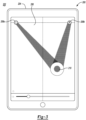
- FIGURE 3 generally depicts one example of an audio system 200 that calibrates a loudspeaker system 202 for achieving a sweet spot for a listener.
- the system 200 includes an audio source 204 that may be in the form of a tablet having a built-in microphone (not shown).
- the audio source 204 includes a user interface 206 that enables a user to specify a distance for each speaker as generally shown on a display of the user interface 206 (e.g., see reference elements 208a and 208b which correspond to visual indicators of a left loudspeaker assembly and a right loudspeaker assembly, respectively) in relation to a visual indicator of the audio source 204 (e.g., see reference element 210) on the user interface 206.
- the audio source 204 stores information corresponding to the distance settings as entered by the user and adjusts the delay of the transmission of the audio signal to the loudspeaker system 200 accordingly.
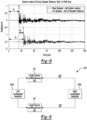
- FIGURE 4 generally depicts the audio system 100 performing a sweet spot calibration for a beamforming loudspeaker system in accordance to one embodiment.
- the audio source 101 is generally equipped with at least one microphone 106 (hereafter "microphone 106") to perform the calibration.
- the audio source 101 may wirelessly transmit a stimulus signal to the left and the right loudspeaker assemblies 102a, 102b to play back audio.
- the left and the right loudspeaker assemblies 102a, 102b transmit the audio output. It is recognized that the stimulus signal is not audible.
- the microphone 106 captures the audio output provided from the left and the right loudspeaker assemblies 102a, 102b.
- a stable round trip latency may be required from the transmission of the stimulus signal, to the receipt and playback of the audio output, and finally for the recording of the audio output on the microphone 106.
- a jitter associated with round-trip latency must be stable and the jitter must be between +/- 145 microseconds which generally equals 7 samples of audio data on the audio output @ 48kHz. This may ensure that the audio source 101 is capable of ascertaining the distance of each of the left loudspeaker assembly 102a and the right loudspeaker assembly 102b therefrom within +/- 5 cm.
- the aspects required to perform the sweet spot calibration will be discussed in more detail below.
- FIGURE 5 generally depicts a first aspect that is performed by the system 100 to perform the sweet spot calibration for the beamforming loudspeaker system 102 in accordance to one embodiment.
- the audio source 101 determines the distance between the loudspeaker assemblies 102a, 102b after a first stimulus signal is sent.
- a user may place the audio source 101 proximate to the left or right loudspeaker assemblies 102a, 102b.
- the user may place the audio source 101 within 5 cm of the left or right loudspeaker assemblies 102a, 102b.
- the user may activate the left or the right loudspeaker assembly 102a, 102b to transmit the audio output to the audio source 101 as an omnidirectional beam as opposed to a directional beam (or beamforming beam with a predetermined directivity) in response to the stimulus signal.
- the left or right loudspeaker assemblies 102a, 102b transmit the audio output with a large horizontal angle that spans from -180 degrees to +180 degrees (e.g, omnidirectional) as illustrated in the signal contour block 300 of Figure 6 (e.g., see axis 302 of Figure 6 ).
- the left and/or the right loudspeaker assemblies 102a and 102b transmit the audio signal within a frequency range (or a predetermined frequency range) of 250 Hz to roughly 1.5 kHz (see axis 304 of Figure 6 ).
- Axis 306 as provided in Figure 6 corresponds to the attenuation of the signal at various decibel levels.
- the stimulus signal has a bandwidth from 250Hz to roughly 1.5 kHz such that the loudspeaker assemblies 102a, 102b play back audio at this frequency range.
- the stimulus signal includes a bandwidth from 250 Hz to 1.5 kHz to enable the left or right loudspeaker assemblies 102a and 102b to control directivity at this frequency range with high performance.
- Placing the audio source 101 proximate to the either the left or right loudspeaker assemblies 102a, 102b calibrates the system latency and the distance between such loudspeaker assemblies 102a, 102b. For example, the audio source 101 performs a time of flight calculation to determine the distance between the left or right loudspeaker assemblies 102a, 102b.
- Figure 7 depicts the system 100 including a distance between the left loudspeaker assembly 102a and the right loudspeaker assembly 102b.
- a system latency, s t is shown in connection with the stimulus signal.
- the system latency s t may be 30 msec.
- Figures 7 and 8 provide additional information with respect to the manner in which the distance is determined.
- FIGURE 9 generally depicts a second aspect that is performed by the audio system 100 to perform the sweet spot calibration for the beamforming loudspeaker system 102 in accordance to one embodiment.
- the audio source 101 transmits a second stimulus signal that may be omnidirectional to determine the distance for each loudspeaker assembly 102a, 102b relative to the audio source 101.
- a second stimulus signal may be omnidirectional to determine the distance for each loudspeaker assembly 102a, 102b relative to the audio source 101.
- an ambiguity arises in that the location (e.g., angle) for each loudspeaker assembly 102a, 102b may not be known.
- the audio source 101 determines the distance to the left and/or right loudspeaker assemblies 102a, 102b as noted above in connection with Figure 5 , the audio source 101 is required to resolve an ambiguity with respect to the position of the left and/or right loudspeaker assemblies 102a, 102b in relation to the audio source 101. For example, while the audio source 101 can determine the distance to the left and/or right loudspeaker assemblies 102a, 102b; it is not known whether the left and/or right loudspeaker assemblies 102a, 102b are positioned in front of the audio source 101 or positioned behind (or rearward) the audio source 101.
- a distance between the audio source 101 and the left loudspeaker assembly 102a is generally defined by the variable, L and a distance between the audio source 101 and the right loudspeaker assembly 102b is generally defined by the variable, R.
- L and R will be discussed in more detail in connection with FIGURE 10 .
- FIGURE 9 illustrates that the audio source 101 is positioned at location 320 that may be in front of the left and right loudspeaker assemblies 102a, 102b or that the audio source 101 may be positioned at location 322 may be positioned behind, or rearward of the left and right loudspeaker assemblies 102a, 102b. In this case, there is an ambiguity that needs to be resolved.
- the sweet spot can be positioned in front of the left and/or right loudspeaker assemblies 102a, 102b or behind (or rearward) of the left and/or right loudspeaker assemblies 102a, 102b.
- the audio source 101 transmits the stimulus signal to the left and right loudspeaker assemblies 102a, 102b.
- the left and right loudspeaker assemblies 102a, 102b transmit an audio output with directivity (e.g., not as an omni-directional beam as transmitted in connection with Figure 5 ) in accordance to beamforming principles in a single direction to the audio source 101.
- the audio source 101 transmits a separate control signal (that is different from the stimulus signal) that instructs the loudspeaker to transmit the audio output at a directivity field (not the omnidirectional field as discussed above in connection with Figures 4 and 6 ).
- the control signal as transmitted by the audio source 101 to the left and right loudspeaker assemblies 102a, 102b also provides a corresponding angle (e.g., ⁇ - for the left loudspeaker assembly 102a and ⁇ for the right loudspeaker assembly 102b) for the left and right loudspeaker assemblies 102a, 102b to transmit audio output signal to resolve the ambiguity.
- a corresponding angle e.g., ⁇ - for the left loudspeaker assembly 102a and ⁇ for the right loudspeaker assembly 102b
- FIGURE 10 depicts an example as to the manner in which the audio source 101 determines angles ⁇ and ⁇ for the left and right loudspeaker assemblies 102a, 102b, respectively.
- the audio source 101 determines the distance, L between the audio source 101 and the left loudspeaker assembly 102a and the distance, R between the audio source 101 and the right loudspeaker assembly 102b.
- the system 100 as illustrated in connection with FIGURE 10 provides a plurality of delay blocks 110a - 110c.
- the delay block 110a generally corresponds to a signal delay (or delay latency) associated with the transmission of the control signal from the audio source 101 to the left and right loudspeaker assemblies 102a, 102b.
- the delay block 110b generally corresponds to a signal delay associated with the transmission of the audio output signal from the left loudspeaker assembly 102a to the microphone 106 of the audio source 101 (e.g., acoustic delay of the left loudspeaker assembly 102a).
- the delay block 110c generally corresponds to a signal delay associated with the transmission of the audio output signal from the right loudspeaker assembly 102b to the microphone 106 of the audio source 101 (e.g., acoustic delay of the left loudspeaker assembly 102a).
- the audio source 101 determines the distance, d between the left and the right loudspeaker assemblies 102a and 102b as noted above in connection with Eq. 2 above. respectively, in addition to the distance, L between the audio source 101 and the left loudspeaker assembly 102a and the distance, R between the audio source 101 and the right loudspeaker assembly 102b, the audio source 101 utilizes the distances d, L, and R to determine the corresponding angles ⁇ and ⁇ .
- the audio source 101 transmits a stimulus signal to the left and right loudspeaker assemblies 102a, 102b such that these assemblies 102a, 102b transmit audio output signals in an omnidirectional range as similarly noted in connection with FIGURES 5 and 6 above.
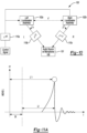
- FIGURE 11A depicts an example of a measurement performed by the audio source 101 with respect to the audio output from the left loudspeaker assembly 102a.
- the audio source 101 determines a peak amplitude L' t of the audio output from the left loudspeaker assembly 102a, wherein the peak amplitude L ' t corresponds to a length of time that it takes for the audio output from the left loudspeaker assembly 102a to reach a peak value.
- the audio source 101 determines the time of flight, l t with respect to the audio output from the left loudspeaker assembly 102a.
- FIGURE 11B depicts an example of a measurement performed by the audio source 101 with respect to the audio output from the right loudspeaker assembly 102b.
- the audio source 101 determines a peak amplitude R ' t of the audio output from the right loudspeaker assembly 102b, wherein the peak amplitude R' t corresponds to a length of time that it takes for the audio output from the right loudspeaker assembly 102b to reach a peak value.
- the audio source 101 includes information corresponding to the angles ⁇ and ⁇ on the control signal as transmitted to the left and right loudspeaker assemblies 102a, 102b such that the left and right loudspeaker assemblies 102a, 102b transmit audio data in a field that is directive (e.g., narrow audio field that is not omnidirectional) at these corresponding angles ⁇ and ⁇ , respectively.
- a field that is directive e.g., narrow audio field that is not omnidirectional
- the audio source 101 determines which of the audio data as received from the left loudspeaker assembly 102a and the right loudspeaker assembly 102b is the loudest in order to remove the ambiguity as noted above. This aspect will be discussed in more detail below.
- FIGURE 12 generally depicts one example of the manner in which the ambiguity of the system 100 is resolved and the manner in which the system 100 determines the sweet spot (S1 or S2) for the listener 104 in accordance to a third aspect.
- the audio source 101 determines the corresponding angles (e.g., ⁇ - for the left loudspeaker assembly 102a and ⁇ for the right loudspeaker assembly 102b)
- the audio source 101 transmits information corresponding to the angle ⁇ and ⁇ to the left and the right loudspeaker assemblies 102a and 102b, respectively.
- FIGURE 12 depicts two corresponding angles (e.g., ⁇ 1 , ⁇ 2 ) where only information to one of these angles may be transmitted on the control signal for the left loudspeaker assembly 102a to transmit the audio output signal to determine the sweet spot location.
- ⁇ 1 or ⁇ 2 may be positive or negative.
- angle ⁇ 1 can be defined as - ⁇ and angle ⁇ 2 can be defined as defined as + ⁇ .
- ⁇ 1 or ⁇ 2 may be positive or negative.
- angle ⁇ 1 can be defined as - ⁇ and angle ⁇ 2 can be defined as defined as + ⁇ .
- two audio sources 101 are provided for purposes of illustration. However, in implementation, only one of these audio sources 101 may actually be provided. In general, it is not known where the audio source 101 is located in reference to the left and the right loudspeaker assemblies 102a and 102b which is the reason for illustrating two audio sources 101. In general, the audio source 101 provides a control signal with information corresponding to the angle - ⁇ to the left loudspeaker assembly 102a (with directivity) and the audio source 101 provides the control signal with information corresponding to the angle + ⁇ to the right loudspeaker assembly 102b (e.g., the angles - ⁇ 1 and + ⁇ are determined based on equations 7 and 8 as noted above).
- the left loudspeaker assembly 102a transmits the audio output signal toward the sweet spot S2 and the right loudspeaker assembly 102b transmits the audio output signal toward the sweet spot S1.
- the actual sweet spot is only that the sweet spot may correspond to S1 or S2 locations.
- the audio source 101 performs a measurement of the peak amplitude of the audio output signal as received from the left loudspeaker assembly 102a and the right loudspeaker assembly 102b in response to such assemblies 102a and 102b transmitting the audio output signals at the angles - ⁇ , + ⁇ ; respectively.
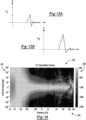
- FIGUREs 13A and 13B generally illustrate the peak amplitude of the audio output from the left loudspeaker assembly 102a and the right loudspeaker assembly 102b.
- the audio source 101 determines which peak amplitude of the audio output signal from the right loudspeaker assembly 102b (i.e., a R ) is the loudest (e.g., see FIGURE 13B ).
- a R e.g., the measured peak amplitude
- the sweet spot is determined to be at location S1.
- FIGURE 13a and 13b corresponds to this condition and S1 is determined to be the sweet spot since the peak amplitude of a R is greater than the measured peak amplitude of a L .
- the audio source 101 is located in the bottom of Figure 12 (or in front of the left and right loudspeaker assemblies 102a - 102b).
- audio source 101 determines that the location of the sweet spot is at S1
- audio source 101 transmits another control signal such that the left loudspeaker assembly 102a transmits the audio output at an angle + ⁇ (note that this is the opposite of angle - ⁇ - which was used to determine the location of the sweet spot S1 and noted directly above) and the right loudspeaker assembly 102b continues to transmit the audio output at the angle + ⁇ such that the audio output from each of the left loudspeaker assembly 102a and the right loudspeaker assembly 102b is directed to the sweet spot S1.
- the sweet spot is determined to be at location S2.
- the audio source 101 is located at the top of Figure 12 (or behind the left and right loudspeaker assemblies 102a - 102b).
- audio source 101 determines that the location of the sweet spot is at S2
- audio source 101 transmits another control signal such that the left loudspeaker assembly 102a continues to transmit the audio output at an angle - ⁇ and the right loudspeaker assembly 102b transmits the audio output at the angle - ⁇ ((note that this is the opposite of angle + ⁇ )) which was used to determine the location of the sweet spot S1 and noted directly above) such that the audio output from each of the left loudspeaker assembly 102a and the right loudspeaker assembly 102b is directed to the sweet spot S2.
- FIGURE 14 generally depicts a signal contour 500 for an output of the left or right beamforming loudspeaker assemblies 102a, 102b in connection with the third aspect as set forth in FIGURE 12 .
- the left or right loudspeaker assembly 102a, 102b transmits the audio output with a small horizontal angle that spans from -50 degrees to +50 degrees as illustrated in the signal contour block 300 of Figure 9 (e.g., see axis 502 of Figure 6 ).
- the left and/or the right loudspeaker assemblies 102a and 102b transmit the audio signal within a frequency range of 250 Hz to roughly 1.5 kHz (see axis 504 of Figure 9 ).
- the frequency is controlled so that the audio output (e.g., from the left and or right loudspeaker assemblies 102a, 102b) is properly received at the audio source 101 to determine the loudness of the left and right loudspeaker assemblies 102a, 102b.
- the directivity e.g., omni directional or beamforming with narrow beam
- this frequency range e.g., 250 Hz to 1.5 KHz
- the audio output signals from the left and the right loudspeaker assemblies 102a, 102b is of narrow directivity (e.g., not omnidirectional) and is within the noted frequency range.
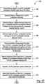
- FIGURE 15 depicts a method 600 for performing sweet spot calibration for a beamforming loudspeaker system in accordance to one embodiment.
- the audio source 101 transmits a stimulus signal to the left loudspeaker assembly 102a and to the right loudspeaker assembly 102b to establish a stable round trip latency (e.g., s t ).
- a stable round trip latency e.g., s t
- the jitter associated with the round-trip latency must be stable and the jitter should be between +/- 145 microseconds which generally equals 7 samples of audio on the audio output @48kHz as provided by the left and the right loudspeaker assemblies 102a and 102b.
- the stable round-trip latency may be 30 msec. This aspect is described in more detail in connection with FIGURE 4 above.
- the audio source 101 determines the distance, d between the left and the right loudspeaker assemblies 102a, 102b. As noted above in connection with FIGURE 7 , the audio source 101 determines the speaker distance or the time of flight (e.g., d r ) that corresponds to the distance and calculates distance d based on Eq. (2) as set forth above.
- the audio source 101 determines the speaker distance or the time of flight (e.g., d r ) that corresponds to the distance and calculates distance d based on Eq. (2) as set forth above.
- the audio source 101 determines the distance, L between the audio source 101 and the left loudspeaker assembly 102a.
- the audio source 101 also determines the distance, R between the audio source 101 and the right loudspeaker assembly based on Eqs. 4 and 6 as noted above.
- the audio source 101 determines the angle, ⁇ for the left loudspeaker assembly and the angle, ⁇ for the right loudspeaker assembly based on Eqs. 7 and 8 as noted above.
- the audio source 101 transmits information corresponding to the angle (e.g., ⁇ ) to the left loudspeaker assembly 102a and transmits information corresponding to the angle (e.g., ⁇ ) to the right loudspeaker assembly 102b to determine the location of the sweet spot.
- the angle e.g., ⁇
- the audio source 101 measures an amplitude of the audio output from the left loudspeaker assembly 102a (e.g., a L ) and measures an amplitude of the audio output from the right loudspeaker assembly (e.g, a R ) .
- the audio source 101 compares a L to a R to determine the location of the sweet spot.
- the sweet spot generally corresponds to a location or a position in which the audio output from the left loudspeaker assembly 102a and the right loudspeaker assembly 102b is perceived by a listener as having a similar loudness and a similar acoustic delay.
- the audio source 101 adjusts angle information for either the left loudspeaker assembly 102a or the right loudspeaker assembly 102b to transmit the audio output to the location of the sweet spot as noted in connection with FIGURE 12 above.
Landscapes
- Physics & Mathematics (AREA)
- Engineering & Computer Science (AREA)
- Acoustics & Sound (AREA)
- Signal Processing (AREA)
- Health & Medical Sciences (AREA)
- Otolaryngology (AREA)
- General Health & Medical Sciences (AREA)
- Circuit For Audible Band Transducer (AREA)
- Stereophonic System (AREA)
Claims (8)
- System (100) zum Bestimmen eines Ortes für ein Strahlformungs-Lautsprechersystem (102) zum Übertragen einer Audioausgabe an dieses, wobei das System (100) umfasst:eine Speichervorrichtung; undeine Audioquelle (101) die die Speichervorrichtung beinhaltet und zu Folgendem konfiguriert ist:Übertragen eines ersten Stimulussignals an eine von einer ersten Strahlformungs-Lautsprecherbaugruppe (102a) und einer zweiten Strahlformungs-Lautsprecherbaugruppe (102b), um eine Audioausgabe abzuspielen;Empfangen der Audioausgabe von der einen von der ersten Strahlformungs-Lautsprecherbaugruppe (102a) und der zweiten Strahlformungs-Lautsprecherbaugruppe (102b);Bestimmen eines ersten Abstands zwischen einer ersten Strahlformungs-Lautsprecheranordnung (102a) und einer zweiten Strahlformungs-Lautsprecher Baugruppe (102b);Bestimmen eines zweiten Abstands zwischen der Audioquelle (101) und der ersten Strahlformungs-Lautsprecherbaugruppe (102a);Bestimmen eines dritten Abstands zwischen der Audioquelle (101) und der zweiten Strahlformungs-Lautsprecherbaugruppe (102b); undBestimmen eines Orts zum Übertragen der Audioausgabe von jeder von der ersten Strahlformungs-Lautsprecherbaugruppe (102a) und der zweiten Strahlformungs-Lautsprecherbaugruppe (102b) zumindest auf der Grundlage der ersten Entfernung, der zweiten Entfernung und der dritten Entfernung,wobei die Audioquelle (101) ferner konfiguriert ist, um einen ersten Winkel für die erste Strahlformungs-Lautsprecherbaugruppe (102a) zu bestimmen, um die Audioausgabe davon basierend zumindest auf dem ersten Abstand, dem zweiten Abstand und dem dritten Abstand zu übertragen, bevor der Ort für die Audioausgabe bestimmt wird,wobei die Audioquelle (101) ferner konfiguriert ist, um einen zweiten Winkel für die zweite Strahlformungs-Lautsprecherbaugruppe (102b) zu bestimmen, um die Audioausgabe davon basierend zumindest auf dem ersten Abstand, dem zweiten Abstand und dem dritten Abstand zu übertragen, bevor der Ort für die Audioausgabe bestimmt wird,wobei die Audioquelle (101) ferner konfiguriert ist, um eine erste Spitzenamplitude der Audioausgabe von der ersten Strahlformungs-Lautsprecherbaugruppe (102a) zu messen, nachdem die erste Strahlformungs-Lautsprecherbaugruppe (102a) die Audioausgabe im ersten Winkel überträgt,wobei die Audioquelle (101) konfiguriert ist, um eine zweite Spitzenamplitude der Audioausgabe von der zweiten Strahlformungs-Lautsprecherbaugruppe zu messen (102b), nachdem die zweite Strahlformungs-Lautsprecherbaugruppe (102b) die Audioausgabe im zweiten Winkel überträgt, undwobei die Audioquelle (101) die erste Spitzenamplitude mit der zweiten Spitzenamplitude vergleicht, um den Ort zum Übertragen der Audioausgabe von jeder der ersten Strahlformungs-Lautsprecherbaugruppe (102a) und der zweiten Strahlformungs-Lautsprecherbaugruppe (102b) zu bestimmen.
- System (100) nach Anspruch 1, wobei die Audioquelle (101) ferner konfiguriert ist, um den ersten Winkel auf einem Steuersignal an die erste Strahlformungs-Lautsprecherbaugruppe (102a) zu übertragen, um die Audioausgabe bei einem schmalen Richtungsfeld gemäß dem ersten Winkel und innerhalb eines ersten vorbestimmten Frequenzbereichs zu übertragen.
- System (100) nach Anspruch 2, wobei der erste vorbestimmte Frequenzbereich innerhalb von 250 Hz bis 1,5 KHz liegt.
- System (100) nach Anspruch 1, wobei die Audioquelle (101) ferner konfiguriert ist, den zweiten Winkel auf einem Steuersignal an die zweite Strahlformungs-Lautsprecherbaugruppe (102b) zu übertragen um die Audioausgabe mit einem schmalen Richtfeld in Übereinstimmung mit dem zweiten Winkel und innerhalb eines vorgegebenen Frequenzbereichs zu übertragen.
- System (100) nach Anspruch 4, wobei der erste vorbestimmte Frequenzbereich innerhalb von 250 Hz bis 1,5 KHz liegt.
- System (100) nach Anspruch 1, wobei der Ort einer Position entspricht, in der die Audioausgabe von der ersten Strahlformungs-Lautsprecherbaugruppe (102a) und der zweiten Strahlformungs-Lautsprecherbaugruppe (102b) von einem Hörer als mit einer ähnlichen Lautstärke und akustischen Verzögerung wahrgenommen wird.
- Computerprogrammprodukt, das in einem nicht-flüchtigen computerlesbaren Medium ausgebildet ist, das programmiert ist, einen Ort für ein Strahlformungs-Lautsprechersystem (102) zu bestimmen, um eine Audioausgabe an dieses zu übertragen, wobei das Computerprogrammprodukt Anweisungen zu Folgendem umfasst:Übertragen eines ersten Stimulussignals an eine einer ersten Strahlformungs-Lautsprecherbaugruppe (102a) und einer zweiten Strahlformungs-Lautsprecherbaugruppe (102b), um eine Audioausgabe abzuspielen;Empfangen der Audioausgabe von einer von der ersten Strahlformungs-Lautsprecherbaugruppe (102a) und der zweiten Strahlformungs-Lautsprecherbaugruppe (102b);Bestimmen eines ersten Abstands zwischen einer ersten Strahlformungs-Lautsprecherbgaugruppe (102a) und einer zweiten Strahlformungs-Lautsprecherbaugruppe (102b);Bestimmen eines zweiten Abstands zwischen einer Audioquelle (101) und der ersten Strahlformungs-Lautsprecherbaugruppe (102a) ;Bestimmen eines dritten Abstands zwischen der Audioquelle (101) und der zweiten Strahlformungs-Lautsprecher Baugruppe (102b);Bestimmen eines Orts für das Übertragen der Audioausgabe von jeder von der ersten Strahlformungs-Lautsprecherbaugruppe (102a) und der zweiten Strahlformungs-Lautsprecherbaugruppe (102b) zumindest auf der Grundlage der ersten Entfernung, der zweiten Entfernung und der dritten Entfernung;Bestimmen eines ersten Winkels für die erste Strahlformungs-Lautsprecherbaugruppe (102a), um die Audioausgabe davon zumindest auf der Grundlage der ersten Entfernung, der zweiten Entfernung und der dritten Entfernung zu übertragen, bevor der Ort für die Audioausgabe bestimmt wird;Bestimmen eines zweiten Winkels für die zweite Strahlformungs-Lautsprecherbaugruppe (102b), um die Audioausgabe davon zumindest auf der Grundlage der ersten Entfernung, der zweiten Entfernung und der dritten Entfernung zu übertragen, bevor der Ort für die Audioausgabe bestimmt wird,Messen einer ersten Spitzenamplitude der Audioausgabe von der ersten Strahlformungs-Lautsprecherbaugruppe (102a), nachdem die erste Strahlformungs-Lautsprecherbaugruppe (102a) die Audioausgabe im ersten Winkel überträgt,Messen einer zweiten Spitzenamplitude der Audioausgabe von der zweiten Strahlformungs-Lautsprecherbaugruppe (102b), nachdem die zweite Strahlformungs-Lautsprecherbaugruppe (102b) die Audioausgabe im zweiten Winkel überträgt, undVergleichen der ersten Spitzenamplitude mit der zweiten Spitzenamplitude, um den Ort zum Übertragen der Audioausgabe von jeder von der ersten Strahlformungs-Lautsprecherbaugruppe (102a) und der zweiten Strahlformungs-Lautsprecherbaugruppe (102b) zu bestimmen.
- Computerprogrammprodukt nach Anspruch 7, ferner umfassend Anweisungen zum Übertragen des ersten Winkels auf einem Steuersignal an die erste Strahlformungs-Lautsprecherbaugruppe (102a), um die Audioausgabe in einem engen Richtfeld entsprechend dem ersten Winkel und innerhalb eines ersten vorgegebenen Frequenzbereichs zu übertragen.
Applications Claiming Priority (1)
| Application Number | Priority Date | Filing Date | Title |
|---|---|---|---|
| US16/541,838 US10820129B1 (en) | 2019-08-15 | 2019-08-15 | System and method for performing automatic sweet spot calibration for beamforming loudspeakers |
Publications (2)
| Publication Number | Publication Date |
|---|---|
| EP3780658A1 EP3780658A1 (de) | 2021-02-17 |
| EP3780658B1 true EP3780658B1 (de) | 2025-02-26 |
Family
ID=72086754
Family Applications (1)
| Application Number | Title | Priority Date | Filing Date |
|---|---|---|---|
| EP20190906.6A Active EP3780658B1 (de) | 2019-08-15 | 2020-08-13 | System und verfahren durchführung von automatischer sweet-spot-kalibrierung für strahlformende lautsprecher |
Country Status (5)
| Country | Link |
|---|---|
| US (1) | US10820129B1 (de) |
| EP (1) | EP3780658B1 (de) |
| JP (1) | JP7638637B2 (de) |
| KR (1) | KR102927843B1 (de) |
| CN (1) | CN112399327A (de) |
Family Cites Families (20)
| Publication number | Priority date | Publication date | Assignee | Title |
|---|---|---|---|---|
| JP4765289B2 (ja) * | 2003-12-10 | 2011-09-07 | ソニー株式会社 | 音響システムにおけるスピーカ装置の配置関係検出方法、音響システム、サーバ装置およびスピーカ装置 |
| US7720232B2 (en) * | 2004-10-15 | 2010-05-18 | Lifesize Communications, Inc. | Speakerphone |
| KR100677554B1 (ko) * | 2005-01-14 | 2007-02-02 | 삼성전자주식회사 | 비임형성 방식을 이용한 녹음 장치 및 그 방법 |
| DE602006016121D1 (de) * | 2005-06-09 | 2010-09-23 | Koninkl Philips Electronics Nv | Verfahren und system zur ermittlung des abstands zwischen lautsprechern |
| JP4802580B2 (ja) * | 2005-07-08 | 2011-10-26 | ヤマハ株式会社 | オーディオ装置 |
| EP1961263A1 (de) * | 2005-12-16 | 2008-08-27 | TC Electronic A/S | Verfahren zum durchführen von messungen mittels eines audiosystems mit passiven lautsprechern |
| WO2009010832A1 (en) * | 2007-07-18 | 2009-01-22 | Bang & Olufsen A/S | Loudspeaker position estimation |
| JP5686358B2 (ja) * | 2008-03-07 | 2015-03-18 | 学校法人日本大学 | 音源距離計測装置及びそれを用いた音響情報分離装置 |
| US20110091055A1 (en) * | 2009-10-19 | 2011-04-21 | Broadcom Corporation | Loudspeaker localization techniques |
| EP2572212B1 (de) * | 2010-05-20 | 2013-12-25 | Koninklijke Philips N.V. | Distanzschätzung mit tonsignalen |
| MX2013006069A (es) * | 2010-12-03 | 2013-10-30 | Fraunhofer Ges Forschung | Aparato y metodo para la adquisicion espacialmente selectiva del sonido mediante triangulacion acustica. |
| KR101708522B1 (ko) * | 2012-05-31 | 2017-02-20 | 한국전자통신연구원 | 오디오 신호 처리 방법 및 장치, 오디오 재생 시스템 |
| US20140003635A1 (en) * | 2012-07-02 | 2014-01-02 | Qualcomm Incorporated | Audio signal processing device calibration |
| EP3072315B1 (de) * | 2013-11-22 | 2021-11-03 | Apple Inc. | Konfiguration von freisprech-abstrahlcharakteristiken |
| US9560445B2 (en) * | 2014-01-18 | 2017-01-31 | Microsoft Technology Licensing, Llc | Enhanced spatial impression for home audio |
| KR102114226B1 (ko) * | 2014-09-26 | 2020-05-25 | 애플 인크. | 구성가능한 구역을 구비한 오디오 시스템 |
| WO2017039633A1 (en) * | 2015-08-31 | 2017-03-09 | Nunntawi Dynamics Llc | Spatial compressor for beamforming speakers |
| EP3188504B1 (de) * | 2016-01-04 | 2020-07-29 | Harman Becker Automotive Systems GmbH | Multimedia-wiedergabe für eine vielzahl von empfängern |
| US20180060025A1 (en) * | 2016-08-31 | 2018-03-01 | Harman International Industries, Incorporated | Mobile interface for loudspeaker control |
| US10299060B2 (en) * | 2016-12-30 | 2019-05-21 | Caavo Inc | Determining distances and angles between speakers and other home theater components |
-
2019
- 2019-08-15 US US16/541,838 patent/US10820129B1/en active Active
-
2020
- 2020-07-28 KR KR1020200093431A patent/KR102927843B1/ko active Active
- 2020-07-29 JP JP2020128255A patent/JP7638637B2/ja active Active
- 2020-08-13 EP EP20190906.6A patent/EP3780658B1/de active Active
- 2020-08-14 CN CN202010816543.6A patent/CN112399327A/zh active Pending
Also Published As
| Publication number | Publication date |
|---|---|
| US10820129B1 (en) | 2020-10-27 |
| EP3780658A1 (de) | 2021-02-17 |
| JP2021035048A (ja) | 2021-03-01 |
| KR20210020779A (ko) | 2021-02-24 |
| CN112399327A (zh) | 2021-02-23 |
| JP7638637B2 (ja) | 2025-03-04 |
| KR102927843B1 (ko) | 2026-02-12 |
Similar Documents
| Publication | Publication Date | Title |
|---|---|---|
| EP1760920B1 (de) | Lautsprecher-gruppeneinrichtung und verfahren zum setzen eines schallstrahls einer lautsprechergruppeneinrichtung | |
| KR101914406B1 (ko) | 배향 응답성 음향 구동기 동작 | |
| US8837743B2 (en) | Surround sound system and method therefor | |
| US7822496B2 (en) | Audio signal processing method and apparatus | |
| US20060165242A1 (en) | Sound reinforcement system | |
| US9549266B2 (en) | Method of controlling a hearing instrument | |
| US7885424B2 (en) | Audio signal supply apparatus | |
| AU2016219549A1 (en) | System and method for enhancing virtual audio height perception | |
| EP2222092B1 (de) | Gruppenlautsprechervorrichtung und Signalverarbeitungsverfahren | |
| EP1463379A2 (de) | System zur Einstellung des Schallfeldes | |
| JP4175420B2 (ja) | スピーカアレイ装置 | |
| EP1511358A2 (de) | Automatisches Schallfeldkorrekturgerät und entsprechendes Computerprogramm | |
| CN101138276B (zh) | 环绕声系统 | |
| US20190069119A1 (en) | Directivity adjustment for reducing early reflections and comb filtering | |
| RU2762879C1 (ru) | Способ обработки звукового сигнала и устройство обработки звукового сигнала | |
| EP3780658A1 (de) | System und verfahren durchführung von automatischer sweet-spot-kalibrierung für strahlformende lautsprecher | |
| US11956617B2 (en) | Audio system | |
| JPH11331999A5 (de) | ||
| JP2011155500A (ja) | モニタ制御装置及び音響システム | |
| JP4405131B2 (ja) | オーディオ装置 | |
| KR20170109145A (ko) | 스피커 사운드 분배 장치 및 방법 | |
| HK1235195A1 (en) | System and method for enhancing virtual audio height perception |
Legal Events
| Date | Code | Title | Description |
|---|---|---|---|
| PUAI | Public reference made under article 153(3) epc to a published international application that has entered the european phase |
Free format text: ORIGINAL CODE: 0009012 |
|
| STAA | Information on the status of an ep patent application or granted ep patent |
Free format text: STATUS: THE APPLICATION HAS BEEN PUBLISHED |
|
| AK | Designated contracting states |
Kind code of ref document: A1 Designated state(s): AL AT BE BG CH CY CZ DE DK EE ES FI FR GB GR HR HU IE IS IT LI LT LU LV MC MK MT NL NO PL PT RO RS SE SI SK SM TR |
|
| AX | Request for extension of the european patent |
Extension state: BA ME |
|
| STAA | Information on the status of an ep patent application or granted ep patent |
Free format text: STATUS: REQUEST FOR EXAMINATION WAS MADE |
|
| 17P | Request for examination filed |
Effective date: 20210816 |
|
| RBV | Designated contracting states (corrected) |
Designated state(s): AL AT BE BG CH CY CZ DE DK EE ES FI FR GB GR HR HU IE IS IT LI LT LU LV MC MK MT NL NO PL PT RO RS SE SI SK SM TR |
|
| STAA | Information on the status of an ep patent application or granted ep patent |
Free format text: STATUS: EXAMINATION IS IN PROGRESS |
|
| 17Q | First examination report despatched |
Effective date: 20230103 |
|
| GRAP | Despatch of communication of intention to grant a patent |
Free format text: ORIGINAL CODE: EPIDOSNIGR1 |
|
| STAA | Information on the status of an ep patent application or granted ep patent |
Free format text: STATUS: GRANT OF PATENT IS INTENDED |
|
| INTG | Intention to grant announced |
Effective date: 20240924 |
|
| GRAS | Grant fee paid |
Free format text: ORIGINAL CODE: EPIDOSNIGR3 |
|
| GRAA | (expected) grant |
Free format text: ORIGINAL CODE: 0009210 |
|
| STAA | Information on the status of an ep patent application or granted ep patent |
Free format text: STATUS: THE PATENT HAS BEEN GRANTED |
|
| P01 | Opt-out of the competence of the unified patent court (upc) registered |
Free format text: CASE NUMBER: APP_1376/2025 Effective date: 20250109 |
|
| AK | Designated contracting states |
Kind code of ref document: B1 Designated state(s): AL AT BE BG CH CY CZ DE DK EE ES FI FR GB GR HR HU IE IS IT LI LT LU LV MC MK MT NL NO PL PT RO RS SE SI SK SM TR |
|
| REG | Reference to a national code |
Ref country code: GB Ref legal event code: FG4D |
|
| REG | Reference to a national code |
Ref country code: CH Ref legal event code: EP |
|
| REG | Reference to a national code |
Ref country code: DE Ref legal event code: R096 Ref document number: 602020046663 Country of ref document: DE |
|
| REG | Reference to a national code |
Ref country code: IE Ref legal event code: FG4D |
|
| REG | Reference to a national code |
Ref country code: NL Ref legal event code: MP Effective date: 20250226 |
|
| PG25 | Lapsed in a contracting state [announced via postgrant information from national office to epo] |
Ref country code: RS Free format text: LAPSE BECAUSE OF FAILURE TO SUBMIT A TRANSLATION OF THE DESCRIPTION OR TO PAY THE FEE WITHIN THE PRESCRIBED TIME-LIMIT Effective date: 20250526 |
|
| PG25 | Lapsed in a contracting state [announced via postgrant information from national office to epo] |
Ref country code: FI Free format text: LAPSE BECAUSE OF FAILURE TO SUBMIT A TRANSLATION OF THE DESCRIPTION OR TO PAY THE FEE WITHIN THE PRESCRIBED TIME-LIMIT Effective date: 20250226 |
|
| PG25 | Lapsed in a contracting state [announced via postgrant information from national office to epo] |
Ref country code: PL Free format text: LAPSE BECAUSE OF FAILURE TO SUBMIT A TRANSLATION OF THE DESCRIPTION OR TO PAY THE FEE WITHIN THE PRESCRIBED TIME-LIMIT Effective date: 20250226 |
|
| PG25 | Lapsed in a contracting state [announced via postgrant information from national office to epo] |
Ref country code: ES Free format text: LAPSE BECAUSE OF FAILURE TO SUBMIT A TRANSLATION OF THE DESCRIPTION OR TO PAY THE FEE WITHIN THE PRESCRIBED TIME-LIMIT Effective date: 20250226 |
|
| REG | Reference to a national code |
Ref country code: LT Ref legal event code: MG9D |
|
| PG25 | Lapsed in a contracting state [announced via postgrant information from national office to epo] |
Ref country code: NO Free format text: LAPSE BECAUSE OF FAILURE TO SUBMIT A TRANSLATION OF THE DESCRIPTION OR TO PAY THE FEE WITHIN THE PRESCRIBED TIME-LIMIT Effective date: 20250526 Ref country code: IS Free format text: LAPSE BECAUSE OF FAILURE TO SUBMIT A TRANSLATION OF THE DESCRIPTION OR TO PAY THE FEE WITHIN THE PRESCRIBED TIME-LIMIT Effective date: 20250626 |
|
| PG25 | Lapsed in a contracting state [announced via postgrant information from national office to epo] |
Ref country code: NL Free format text: LAPSE BECAUSE OF FAILURE TO SUBMIT A TRANSLATION OF THE DESCRIPTION OR TO PAY THE FEE WITHIN THE PRESCRIBED TIME-LIMIT Effective date: 20250226 |
|
| PG25 | Lapsed in a contracting state [announced via postgrant information from national office to epo] |
Ref country code: HR Free format text: LAPSE BECAUSE OF FAILURE TO SUBMIT A TRANSLATION OF THE DESCRIPTION OR TO PAY THE FEE WITHIN THE PRESCRIBED TIME-LIMIT Effective date: 20250226 |
|
| PG25 | Lapsed in a contracting state [announced via postgrant information from national office to epo] |
Ref country code: PT Free format text: LAPSE BECAUSE OF FAILURE TO SUBMIT A TRANSLATION OF THE DESCRIPTION OR TO PAY THE FEE WITHIN THE PRESCRIBED TIME-LIMIT Effective date: 20250626 Ref country code: LV Free format text: LAPSE BECAUSE OF FAILURE TO SUBMIT A TRANSLATION OF THE DESCRIPTION OR TO PAY THE FEE WITHIN THE PRESCRIBED TIME-LIMIT Effective date: 20250226 |
|
| PG25 | Lapsed in a contracting state [announced via postgrant information from national office to epo] |
Ref country code: GR Free format text: LAPSE BECAUSE OF FAILURE TO SUBMIT A TRANSLATION OF THE DESCRIPTION OR TO PAY THE FEE WITHIN THE PRESCRIBED TIME-LIMIT Effective date: 20250527 Ref country code: BG Free format text: LAPSE BECAUSE OF FAILURE TO SUBMIT A TRANSLATION OF THE DESCRIPTION OR TO PAY THE FEE WITHIN THE PRESCRIBED TIME-LIMIT Effective date: 20250226 |
|
| REG | Reference to a national code |
Ref country code: AT Ref legal event code: MK05 Ref document number: 1771848 Country of ref document: AT Kind code of ref document: T Effective date: 20250226 |
|
| PG25 | Lapsed in a contracting state [announced via postgrant information from national office to epo] |
Ref country code: SE Free format text: LAPSE BECAUSE OF FAILURE TO SUBMIT A TRANSLATION OF THE DESCRIPTION OR TO PAY THE FEE WITHIN THE PRESCRIBED TIME-LIMIT Effective date: 20250226 |
|
| PG25 | Lapsed in a contracting state [announced via postgrant information from national office to epo] |
Ref country code: SM Free format text: LAPSE BECAUSE OF FAILURE TO SUBMIT A TRANSLATION OF THE DESCRIPTION OR TO PAY THE FEE WITHIN THE PRESCRIBED TIME-LIMIT Effective date: 20250226 |
|
| PG25 | Lapsed in a contracting state [announced via postgrant information from national office to epo] |
Ref country code: DK Free format text: LAPSE BECAUSE OF FAILURE TO SUBMIT A TRANSLATION OF THE DESCRIPTION OR TO PAY THE FEE WITHIN THE PRESCRIBED TIME-LIMIT Effective date: 20250226 |
|
| PGFP | Annual fee paid to national office [announced via postgrant information from national office to epo] |
Ref country code: DE Payment date: 20250724 Year of fee payment: 6 |
|
| PG25 | Lapsed in a contracting state [announced via postgrant information from national office to epo] |
Ref country code: IT Free format text: LAPSE BECAUSE OF FAILURE TO SUBMIT A TRANSLATION OF THE DESCRIPTION OR TO PAY THE FEE WITHIN THE PRESCRIBED TIME-LIMIT Effective date: 20250226 |
|
| PGFP | Annual fee paid to national office [announced via postgrant information from national office to epo] |
Ref country code: GB Payment date: 20250724 Year of fee payment: 6 |
|
| PG25 | Lapsed in a contracting state [announced via postgrant information from national office to epo] |
Ref country code: AT Free format text: LAPSE BECAUSE OF FAILURE TO SUBMIT A TRANSLATION OF THE DESCRIPTION OR TO PAY THE FEE WITHIN THE PRESCRIBED TIME-LIMIT Effective date: 20250226 |
|
| PG25 | Lapsed in a contracting state [announced via postgrant information from national office to epo] |
Ref country code: EE Free format text: LAPSE BECAUSE OF FAILURE TO SUBMIT A TRANSLATION OF THE DESCRIPTION OR TO PAY THE FEE WITHIN THE PRESCRIBED TIME-LIMIT Effective date: 20250226 Ref country code: CZ Free format text: LAPSE BECAUSE OF FAILURE TO SUBMIT A TRANSLATION OF THE DESCRIPTION OR TO PAY THE FEE WITHIN THE PRESCRIBED TIME-LIMIT Effective date: 20250226 |
|
| PG25 | Lapsed in a contracting state [announced via postgrant information from national office to epo] |
Ref country code: RO Free format text: LAPSE BECAUSE OF FAILURE TO SUBMIT A TRANSLATION OF THE DESCRIPTION OR TO PAY THE FEE WITHIN THE PRESCRIBED TIME-LIMIT Effective date: 20250226 |
|
| PG25 | Lapsed in a contracting state [announced via postgrant information from national office to epo] |
Ref country code: SK Free format text: LAPSE BECAUSE OF FAILURE TO SUBMIT A TRANSLATION OF THE DESCRIPTION OR TO PAY THE FEE WITHIN THE PRESCRIBED TIME-LIMIT Effective date: 20250226 |
|
| REG | Reference to a national code |
Ref country code: DE Ref legal event code: R097 Ref document number: 602020046663 Country of ref document: DE |
|
| PLBE | No opposition filed within time limit |
Free format text: ORIGINAL CODE: 0009261 |
|
| STAA | Information on the status of an ep patent application or granted ep patent |
Free format text: STATUS: NO OPPOSITION FILED WITHIN TIME LIMIT |
|
| REG | Reference to a national code |
Ref country code: CH Ref legal event code: L10 Free format text: ST27 STATUS EVENT CODE: U-0-0-L10-L00 (AS PROVIDED BY THE NATIONAL OFFICE) Effective date: 20260107 |
|
| 26N | No opposition filed |
Effective date: 20251127 |
|
| REG | Reference to a national code |
Ref country code: CH Ref legal event code: H13 Free format text: ST27 STATUS EVENT CODE: U-0-0-H10-H13 (AS PROVIDED BY THE NATIONAL OFFICE) Effective date: 20260324 |
|
| PG25 | Lapsed in a contracting state [announced via postgrant information from national office to epo] |
Ref country code: MC Free format text: LAPSE BECAUSE OF FAILURE TO SUBMIT A TRANSLATION OF THE DESCRIPTION OR TO PAY THE FEE WITHIN THE PRESCRIBED TIME-LIMIT Effective date: 20250226 |
|
| PG25 | Lapsed in a contracting state [announced via postgrant information from national office to epo] |
Ref country code: LU Free format text: LAPSE BECAUSE OF NON-PAYMENT OF DUE FEES Effective date: 20250813 |
|
| PG25 | Lapsed in a contracting state [announced via postgrant information from national office to epo] |
Ref country code: CH Free format text: LAPSE BECAUSE OF NON-PAYMENT OF DUE FEES Effective date: 20250831 |