EP3780333B1 - Energiegewinnung aus flugzeugleuchten - Google Patents
Energiegewinnung aus flugzeugleuchten Download PDFInfo
- Publication number
- EP3780333B1 EP3780333B1 EP20190513.0A EP20190513A EP3780333B1 EP 3780333 B1 EP3780333 B1 EP 3780333B1 EP 20190513 A EP20190513 A EP 20190513A EP 3780333 B1 EP3780333 B1 EP 3780333B1
- Authority
- EP
- European Patent Office
- Prior art keywords
- circuitry
- lighting system
- voltage
- energy
- regulator
- Prior art date
- Legal status (The legal status is an assumption and is not a legal conclusion. Google has not performed a legal analysis and makes no representation as to the accuracy of the status listed.)
- Active
Links
Images

Classifications
-
- H—ELECTRICITY
- H02—GENERATION; CONVERSION OR DISTRIBUTION OF ELECTRIC POWER
- H02J—ELECTRIC POWER NETWORKS; CIRCUIT ARRANGEMENTS OR SYSTEMS FOR SUPPLYING OR DISTRIBUTING ELECTRIC POWER; SYSTEMS FOR STORING ELECTRIC ENERGY
- H02J50/00—Circuit arrangements or systems for wireless supply or distribution of electric power
- H02J50/001—Energy harvesting or scavenging
-
- B—PERFORMING OPERATIONS; TRANSPORTING
- B64—AIRCRAFT; AVIATION; COSMONAUTICS
- B64D—EQUIPMENT FOR FITTING IN OR TO AIRCRAFT; FLIGHT SUITS; PARACHUTES; ARRANGEMENT OR MOUNTING OF POWER PLANTS OR PROPULSION TRANSMISSIONS IN AIRCRAFT
- B64D47/00—Equipment not otherwise provided for
- B64D47/02—Arrangements or adaptations of signal or lighting devices
-
- F—MECHANICAL ENGINEERING; LIGHTING; HEATING; WEAPONS; BLASTING
- F21—LIGHTING
- F21S—NON-PORTABLE LIGHTING DEVICES; SYSTEMS THEREOF; VEHICLE LIGHTING DEVICES SPECIALLY ADAPTED FOR VEHICLE EXTERIORS
- F21S9/00—Lighting devices with a built-in power supply; Systems employing lighting devices with a built-in power supply
- F21S9/02—Lighting devices with a built-in power supply; Systems employing lighting devices with a built-in power supply the power supply being a battery or accumulator
-
- F—MECHANICAL ENGINEERING; LIGHTING; HEATING; WEAPONS; BLASTING
- F21—LIGHTING
- F21V—FUNCTIONAL FEATURES OR DETAILS OF LIGHTING DEVICES OR SYSTEMS THEREOF; STRUCTURAL COMBINATIONS OF LIGHTING DEVICES WITH OTHER ARTICLES, NOT OTHERWISE PROVIDED FOR
- F21V23/00—Arrangement of electric circuit elements in or on lighting devices
- F21V23/04—Arrangement of electric circuit elements in or on lighting devices the elements being switches
-
- H—ELECTRICITY
- H02—GENERATION; CONVERSION OR DISTRIBUTION OF ELECTRIC POWER
- H02J—ELECTRIC POWER NETWORKS; CIRCUIT ARRANGEMENTS OR SYSTEMS FOR SUPPLYING OR DISTRIBUTING ELECTRIC POWER; SYSTEMS FOR STORING ELECTRIC ENERGY
- H02J7/00—Circuit arrangements for charging or discharging batteries or for supplying loads from batteries
- H02J7/865—Battery or charger load switching, e.g. concurrent charging and load supply
-
- B—PERFORMING OPERATIONS; TRANSPORTING
- B64—AIRCRAFT; AVIATION; COSMONAUTICS
- B64D—EQUIPMENT FOR FITTING IN OR TO AIRCRAFT; FLIGHT SUITS; PARACHUTES; ARRANGEMENT OR MOUNTING OF POWER PLANTS OR PROPULSION TRANSMISSIONS IN AIRCRAFT
- B64D2203/00—Aircraft or airfield lights using LEDs
-
- H—ELECTRICITY
- H02—GENERATION; CONVERSION OR DISTRIBUTION OF ELECTRIC POWER
- H02N—ELECTRIC MACHINES NOT OTHERWISE PROVIDED FOR
- H02N11/00—Generators or motors not provided for elsewhere; Alleged perpetua mobilia obtained by electric or magnetic means
- H02N11/002—Generators
-
- Y—GENERAL TAGGING OF NEW TECHNOLOGICAL DEVELOPMENTS; GENERAL TAGGING OF CROSS-SECTIONAL TECHNOLOGIES SPANNING OVER SEVERAL SECTIONS OF THE IPC; TECHNICAL SUBJECTS COVERED BY FORMER USPC CROSS-REFERENCE ART COLLECTIONS [XRACs] AND DIGESTS
- Y02—TECHNOLOGIES OR APPLICATIONS FOR MITIGATION OR ADAPTATION AGAINST CLIMATE CHANGE
- Y02T—CLIMATE CHANGE MITIGATION TECHNOLOGIES RELATED TO TRANSPORTATION
- Y02T50/00—Aeronautics or air transport
- Y02T50/50—On board measures aiming to increase energy efficiency
Definitions
- Aircraft lighting systems may illuminate environments inside and outside the aircraft.
- Lighting systems may blink or flicker projected light to increase visual awareness. Energy provided to such lighting systems may be wasted due to heating losses, extraneous lighting, or other forms of energy. Lighting systems may be further subjected to vibrations or other energy forms.
- EP3165890 relates to a system and method for monitoring structural health of bonded components.
- control circuitry defining a control circuitry voltage, the control circuitry operable to output a control signal to the driver.
- further embodiments may include that the regulator voltage is defined at the control circuitry voltage.
- control signal is pulse width modulated.
- control circuitry is a synchronization controller
- control signal includes synchronization commands such that the driver operates according the synchronization commands
- control circuitry is a timing controller
- control signal includes timing commands such that the driver operates according to the timing commands
- further embodiments may include that the energy harvesting circuitry includes a switch operable to disconnect the control circuitry from the regulator when energy from the energy generation circuitry is below a predetermine threshold.
- further embodiments may include monitoring circuitry defining a monitoring circuitry voltage, the monitoring circuitry operable to output diagnostic information related to the lighting system.
- further embodiments may include that the regulator voltage is defined at the monitoring circuitry voltage.
- further embodiments may include that the monitoring circuitry is an elapsed time counter, and the diagnostic information includes an actuation count of the illumination element.
- further embodiments may include that the monitoring circuitry is a luminance monitor, and the diagnostic information includes a maximum luminance of the illumination element.
- further embodiments may include that the monitoring circuitry is a temperature monitor, and the diagnostic information includes a temperature associated with the illumination element.
- further embodiments may include that the monitoring circuitry is a water monitor, and the diagnostic information includes a water indication associated with the housing.
- further embodiments may include that the energy harvesting circuitry includes a switch operable to disconnect the monitoring circuitry from the regulator when energy stored in a capacitor associated with the energy generation circuitry is below a predetermine threshold.
- further embodiments may include that the energy harvesting circuitry supplements the energy from a power connection that provides the energization of the illumination element.
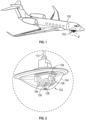
- the aircraft lighting system disposed in an environment of an aircraft.
- the aircraft lighting system includes a housing.
- the aircraft lighting system includes an illumination element disposed within the housing.
- the aircraft lighting system includes energy generation circuitry configured to generate electricity from the environment.
- the aircraft lighting system includes switching circuitry including a driver operable to control illumination of the illumination element and operated with a driver voltage.
- the aircraft lighting system includes control circuitry a control circuitry voltage, the control circuitry operable to output a control signal to the driver.
- the aircraft lighting system includes energy harvesting circuitry including a regulator configured to draw energy from the energy generation circuitry and output a regulator voltage defined at the driver voltage.
- further embodiments may include monitoring circuitry defining a monitoring circuitry voltage and the regulator voltage is defined at the monitoring circuitry voltage, the monitoring circuitry operable to output diagnostic information related to the lighting system.
- the aircraft lighting system disposed in an environment of an aircraft.
- the aircraft lighting system includes a housing.
- the aircraft lighting system includes an illumination element disposed within the housing.
- the aircraft lighting system includes energy generation circuitry configured to generate electricity from the environment.
- the aircraft lighting system includes switching circuitry including a driver operable to control illumination of the illumination element and operated with a driver voltage.
- the aircraft lighting system includes monitoring circuitry defining a monitoring circuitry voltage, the monitoring circuitry operable to output diagnostic information related to the illumination element.
- the aircraft lighting system includes energy harvesting circuitry including a regulator configured to draw energy from the energy generation circuitry and output a regulator voltage defined at the driver voltage.
- Aircraft may include lighting systems to illuminate internal and external environments. Such lighting systems may blink or flicker, requiring additional switching circuitry to control the flow of electricity to illumination elements. Switching circuitry may discharge heat due to switching losses along with other circuitry associated with the lighting system.
- energy harvesting circuitry may be employed to capture wasted energy from heat, light, vibration, and other energy sources.
- heat energy harvesting may be performed by Seebeck generators.
- Light energy harvesting may be performed, as an example, on refracted or reflected light within the lighting system housing by photovoltaic generators.
- vibration energy harvesting may be performed by piezoelectric generators. Further, the generation of blinking or flickering light may enable increased value return for energy harvesting circuitry on aircraft.
- the lighting system 102 may include any number of circuitries or other implementations to perform the requisite actions. Portions of the circuitry may be disposed within the housing 104. Portions of the circuitry may be disposed outside of the housing 104.
- energy generation circuitry 136 may be a Seebeck generator having a hot plate inside the housing 104 and attached to the heatsink 132, while the cold plate may be disposed outside the housing 104.
- the energy generation circuitry 136 may further be disposed as a portion of the housing 104.
- the lighting system 102 may include an illumination element 106.
- the illumination element 106 may also include one or more illumination elements.
- the illumination element 106 may be a light-emitting diode (LED), High Intensity Discharge Lamps, Organic LEDs, incandescent filament, combinations thereof, or any other implement.
- the illumination element 106 may be connected with a printed circuit board 108.
- the printed circuit board 108 may conduct heat from circuitry disposed thereon.
- the lighting system 102 may include an input conduit that includes a power connection 110 to aircraft power systems.
- the power connection 110 may be connected to a 115-volt bus associated with the aircraft 100.
- the 115-volt bus may conduct alternating current.
- the current may alternate at 400 Hz.
- the power connection 110 may receive any type of power to energize the lighting system 102. It should be appreciated that any of the circuitry or functional blocks shown in FIG. 2 may be added, removed, or duplicated based on the type of power received from the power connection 110.
- the printed circuit board 108 may include a heatsink 132.
- the heatsink 132 may be thermally conductive with the entire printed circuit board 108.
- the heatsink 132 is be thermally conductive with the illumination element(s) 106.
- the heatsink 132 may be thermally conductive with any energy generating or heat generating parts associated with the printed circuit board 108.
- One or more printed circuit boards 108 or printed circuit board portions may be used.
- the printed circuit board may include FR-4 or metallic materials.
- the heatsink 132 may be associated with particular heat generative devices on the printed circuit board 108.
- the heatsink 132 provides heat to the energy harvesting circuitry 134.
- the energy generation circuitry 136 is a Seebeck generator having a hot side 166 connected to the heatsink 132 and a cold side 168.
- the cold side 168 may be connected anywhere that is cooler than the heatsink 132.
- the cold side may be connected to or arranged about the housing 104.
- the illumination element 106 may be directly mounted on the printed circuity board 108, heating one side of the printed circuit board 108 to cause the Seebeck Effect.
- the heatsink 132 may be any type of energy-conductive device.
- the heatsink 132 may be a rigid, vibration-transmitting element when associated with energy generation circuitry 136 that is piezoelectric.
- the heatsink 132 may be a light-conduit such as an optical fiber for transmitting light generated by the illumination element 106 when associated with energy generation circuitry 136 that is photovoltaic.
- the energy generation circuitry 136 may be connected with a capacitor 138 or another energy storage device to collect the energy generated by the energy generation circuitry 136.
- the energy stored in the capacitor 138 may be transferred to the regulator 142.
- the regulator 142 may convert the capacitor voltage to suitable regulator voltages for consumption by the switching circuitry 124, the monitoring circuitry 146, and the control circuitry 156.
- the control circuitry 156 may require 15-volt, 5-volt, or 3.3-volt energization.
- the regulator 142 may output a regulator voltage defined commensurate with the monitoring circuitry 146 voltages.
- the elapsed time counter 148 may require a 3.3-volt supply.
- the regulator 142 may include regulatory circuitry operable to provide the 3.3-volt supply.
- the luminance monitor 150 may require a 15-volt supply.
- the regulator 142 may include regulatory circuitry operable to provide the 15-volt supply.
- the temperature monitor 152 may require a 5-volt supply.
- the regulator 142 may include regulatory circuitry operable to provide the 5-volt supply.
- the water ingress monitoring or water monitor 154 may require a 3.3-volt supply.
- the regulator 142 may include regulatory circuitry operable to provide the 3.3-volt supply.
- Monitoring circuitry 146 may record information related to the operation of the lighting system 102 in a data repository or provide information to aircraft controllers.
- the elapsed time counter 148 may provide diagnostic information that includes an actuation count of the illumination element 106. That is, the number of illuminations or a running time of illumination of the illumination element 106 or lighting system 102.
- the luminance monitor 150 may provide diagnostic information that includes a maximum luminance of the illumination element 106. The luminance may be a maximum brightness or a calculated maximum brightness of the illumination element 106.
- the temperature monitor 152 may provide diagnostic information that includes a temperature associated with the illumination element 106.
- the water monitor 154 may provide diagnostic information that includes a water indication or water intrusion indication associated with the housing 104. The water monitor 154 may also provide humidity information associated with the housing 104.
- the regulator 142 may output a regulator voltage defined according to the control circuitry 156 voltages.
- the timing controller 158 may require a 5-volt supply.
- the regulator 142 may include regulatory circuitry operable to provide the 5-volt supply.
- the synchronization controller 160 may require the 3.3-volt supply.
- the regulator 142 may include regulatory circuitry operable to provide a 3.3-volt supply.
- the signal conditioner 162 may require a 15-volt supply.
- the regulator 142 may include regulatory circuitry operable to provide the 15-volt supply.
- the control circuitry 156 may provide command and control signals to the switching circuitry 124.
- the synchronization controller 160 may provide synchronization commands such that the driver 126 operates according the synchronization commands. As such, the illumination element 106 may illuminate according to the illumination of other illumination elements.
- the timing controller 158 may provide timing commands such that the driver 126 operates according to the timing commands. As such, the illumination element 106 may blink at a predetermined rate.
- the signal conditioner 162 may improve the control signal 164 or condition the control signal 164.
- the control signal 164 may be a pulse width modulated signal to the driver 126 or driver integrated circuit 128.
- the regulator 142 may output regulator voltage defined according to the switching circuitry 124 or other circuitry on the printed circuit board 108.
- the driver 126 may require a 28-volt supply.
- the regulator 142 may include regulatory circuitry operable to provide the 28-volt supply.
- the driver integrated circuit 128 may require a 5-volt supply.
- the regulator 142 may include regulatory circuitry operable to provide the 5-volt supply.
- the regulator 142 may be a low-dropout regulator, Zener diode regulator, or another implement.
- a controller 140 may be implemented to provide harvested energy to the monitoring circuitry 146, control circuitry 156, and/or switching circuitry 124 on demand.
- necessary loads may include the control circuitry 156, the monitoring circuitry 146, or portions thereof.
- the controller 140 may operate switches 144 or may be operable to open close the switches 144 to direct harvested energy as necessary.
- the switches 144 may be operable to disconnect the control circuitry 156, the monitoring circuitry 146 or portions thereof based on the energy harvested and stored in the capacitor 138.
- coulomb counting or voltage measurements may determine the energy stored in the capacitor 138.
- the controller 140 may disconnect loads that are not necessary for operation of the illumination element 106 in response to the energy stored in the capacitor 138 falling below a predetermined threshold.
- the luminance monitor 150 may be disconnected when energy falls below the predetermined threshold.
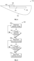
- the generalized flow diagram 200 includes a determination of charge stored in the capacitor 138. If the charge of the capacitor 138 is below a first predetermined threshold, in block 204, the control circuitry 156, or portions thereof, may be disconnected. If the charge of the capacitor 138 is below a second predetermined threshold, in block 208, the switching circuitry 124 may be disconnected in block 210.
- the predetermined thresholds may be an energy storage value calculated by one or more controllers 140. Such disconnection may allow normal auxiliary power to provide energization of such circuits. It should be appreciated that disconnection may be based on the voltage supplied by the regulator 142. Higher voltages may be shed before lower voltages are shed.
- the controller 140 may include any combination of processors, field programmable gate arrays (FPGA), or application specific integrated circuits (ASIC).
- the controller 140 may include memory, volatile and non-volatile, operable to store machine instructions from the processors and other processing mechanisms to receive, calculate, and control devices, as necessary.
- Machine instructions may be stored (e.g., stored instructions, stored machine instructions, stored steps) in any language or representation, including but not limited to machine code, assembly instructions, C, C++, C#, PYTHON, JAVA, and RUBY. It should be appreciated that any type of wired or wireless configuration is appreciated for any of the communications from the controller 140.
- Wireless protocols such as ZIGBEE, WI-FI, Near-Field Communications (NFC), BLUETOOTH, or any other implement may be used. Communications may be realized through any protocol or medium known or unknown. Any number of controllers 140 may be implemented to individually or collectively provide the necessary operations.
Landscapes
- Engineering & Computer Science (AREA)
- General Engineering & Computer Science (AREA)
- Aviation & Aerospace Engineering (AREA)
- Power Engineering (AREA)
- Computer Networks & Wireless Communication (AREA)
- Circuit Arrangement For Electric Light Sources In General (AREA)
Claims (15)
- Flugzeuglichtsystem (102), das in einer Umgebung eines Flugzeugs (100) angeordnet ist, umfassend:ein Gehäuse (104);ein Flugzeugleistungssystem, das dazu konfiguriert ist, elektrische Leistung abzugeben;ein Beleuchtungselement (106), das innerhalb des Gehäuses angeordnet ist; undUmschaltschaltkreise (124), die einen Treiber in Signalkommunikation mit dem Flugzeugleistungssystem über eine Leistungsverbindung (110) beinhalten, um die elektrische Leistung aufzunehmen, und betreibbar, um die Beleuchtung des Beleuchtungselements unter Verwendung der elektrischen Leistung zu steuern, wobei der Treiber mit einer Treiberspannung betrieben wird;ferner umfassend:eine Wärmesenke (132), die an das Beleuchtungselement (106) gekoppelt und zu diesem wärmeleitfähig ist;Energieerzeugungsschaltkreise (136), die dazu konfiguriert sind, Wärme von einer Wärmesenke aufzunehmen, und dazu konfiguriert sind, Elektrizität aus der Umgebung zu erzeugen, um gewonnene Energie zu erzeugen, wobei die Elektrizität gemäß einem durch die Energieerzeugungsschaltkreise (136) durchgeführten Seebeck-Effekt erzeugt wird; undEnergiegewinnungsschaltkreise (134), die einen Regler (142) beinhalten, der dazu konfiguriert ist, die gewonnene Energie aus den Energieerzeugungsschaltkreisen (136) zu entnehmen, um die gewonnene Energie in eine Reglerspannung umzuwandeln und die Reglerspannung mit der Treiberspannung auszugeben.
- Lichtsystem nach Anspruch 1, ferner umfassend Steuerschaltkreise (156), die eine Steuerschaltkreisspannung definieren, wobei die Steuerschaltkreise betreibbar sind, um ein Steuersignal an den Treiber auszugeben.
- Lichtsystem nach Anspruch 2, wobei die Reglerspannung mit der Steuerschaltkreisspannung definiert ist.
- Lichtsystem nach Anspruch 2 oder 3, wobei das Steuersignal pulsbreitenmoduliert ist.
- Lichtsystem nach Anspruch 2, 3 oder 4, wobei es sich bei den Steuerschaltkreisen (156) um eine Synchronisationssteuerung handelt und das Steuersignal Synchronisationsbefehle beinhaltet, sodass der Treiber gemäß den Synchronisationsbefehlen arbeitet.
- Lichtsystem nach Anspruch 2, 3 oder 4, wobei es sich bei den Steuerschaltkreisen (156) um eine Zeitsteuerung handelt und das Steuersignal Zeitsteuerungsbefehle beinhaltet, sodass der Treiber gemäß den Zeitsteuerungsbefehlen arbeitet.
- Lichtsystem nach Anspruch 2, 3 oder 4, wobei es sich bei den Steuerschaltkreisen (156) um einen Signalwandler handelt und das Steuersignal gemäß dem Signalwandler gewandelt wird.
- Lichtsystem nach Anspruch 2, 3, 4, 5, 6 oder 7, wobei die Energiegewinnungsschaltkreise (134) einen Schalter beinhalten, der betreibbar ist, um die Steuerschaltkreise von dem Regler zu trennen, wenn Energie von den Energieerzeugungsschaltkreisen unter einem vorbestimmten Schwellenwert liegt.
- Lichtsystem nach einem der vorstehenden Ansprüche, ferner umfassend Überwachungsschaltkreise (146), die eine Überwachungsschaltkreisspannung definieren, wobei die Überwachungsschaltkreise betreibbar sind, um Diagnoseinformationen bezüglich des Lichtsystems auszugeben.
- Lichtsystem nach Anspruch 9, wobei die Reglerspannung mit der Überwachungsschaltkreisspannung definiert ist.
- Lichtsystem nach Anspruch 9, wobei es sich bei den Überwachungsschaltkreisen (146) um eines oder mehrere von einem Zähler für verstrichene Zeit, einer Helligkeitsüberwachungseinrichtung, einer Temperaturüberwachungseinrichtung, einer Wasserüberwachungseinrichtung handelt; und
wobei die Diagnoseinformationen eines oder mehrere von einer Betätigungszahl des Beleuchtungselements, einer maximalen Helligkeit des Beleuchtungselements, einer dem Beleuchtungselement zugeordneten Temperatur, einer dem Gehäuse zugeordneten Wasserangabe beinhalten. - Lichtsystem nach Anspruch 9, wobei die Energiegewinnungsschaltkreise (134) einen Schalter beinhalten, der betreibbar ist, um die Überwachungsschaltkreise von dem Regler zu trennen, wenn Energie, die in einem den Energieerzeugungsschaltkreisen zugeordneten Kondensator gespeichert ist, unter einem vorbestimmten Schwellenwert liegt, und wobei die Energiegewinnungsschaltkreise die Energie von einer Leistungsverbindung ergänzen, die die Energiezufuhr zu dem Beleuchtungselement bereitstellt.
- Flugzeuglichtsystem nach Anspruch 1, ferner umfassend:
Steuerschaltkreise (156), die eine Steuerschaltkreisspannung definieren, wobei die Steuerschaltkreise betreibbar sind, um ein Steuersignal an den Treiber auszugeben. - Lichtsystem nach Anspruch 13, ferner umfassend Überwachungsschaltkreise (146), die eine Überwachungsschaltkreisspannung definieren, und die Reglerspannung ist mit der Überwachungsschaltkreisspannung definiert, wobei die Überwachungsschaltkreise betreibbar sind, um Diagnoseinformationen bezüglich des Lichtsystems auszugeben.
- Flugzeuglichtsystem nach Anspruch 1, ferner umfassend:
Überwachungsschaltkreise (146), die eine Überwachungsschaltkreisspannung definieren, wobei die Überwachungsschaltkreise betreibbar sind, um Diagnoseinformationen bezüglich des Beleuchtungselements auszugeben.
Applications Claiming Priority (1)
| Application Number | Priority Date | Filing Date | Title |
|---|---|---|---|
| IN201911032888 | 2019-08-14 |
Publications (2)
| Publication Number | Publication Date |
|---|---|
| EP3780333A1 EP3780333A1 (de) | 2021-02-17 |
| EP3780333B1 true EP3780333B1 (de) | 2025-01-22 |
Family
ID=72046765
Family Applications (1)
| Application Number | Title | Priority Date | Filing Date |
|---|---|---|---|
| EP20190513.0A Active EP3780333B1 (de) | 2019-08-14 | 2020-08-11 | Energiegewinnung aus flugzeugleuchten |
Country Status (2)
| Country | Link |
|---|---|
| US (1) | US10919643B1 (de) |
| EP (1) | EP3780333B1 (de) |
Families Citing this family (4)
| Publication number | Priority date | Publication date | Assignee | Title |
|---|---|---|---|---|
| JP2019176574A (ja) * | 2018-03-27 | 2019-10-10 | 豊田合成株式会社 | トランスデューサー装置 |
| US11149921B2 (en) * | 2020-03-23 | 2021-10-19 | AeroLEDS, LLC | Aircraft light collimation and redirection apparatus and method |
| US11718415B2 (en) * | 2021-06-04 | 2023-08-08 | Goodrich Corporation | Energy autonomous aircraft evacuation slide systems and methods |
| EP4098934B1 (de) * | 2021-06-04 | 2026-02-18 | Goodrich Corporation | Energieautarke flugzeugentlastungsgleitsysteme und verfahren |
Family Cites Families (21)
| Publication number | Priority date | Publication date | Assignee | Title |
|---|---|---|---|---|
| US6483258B2 (en) * | 2001-01-31 | 2002-11-19 | Honeywell International Inc. | Infrared fiber optic light |
| US8491159B2 (en) | 2006-03-28 | 2013-07-23 | Wireless Environment, Llc | Wireless emergency lighting system |
| US20080234893A1 (en) | 2007-03-23 | 2008-09-25 | The Boeing Company | Window control system |
| US20100207573A1 (en) | 2009-02-11 | 2010-08-19 | Anthony Mo | Thermoelectric feedback circuit |
| DE102009010180A1 (de) * | 2009-02-23 | 2010-10-28 | Osram Gesellschaft mit beschränkter Haftung | Leuchtvorrichtung mit mindestens einer Halbleiterlichtquelle |
| US20110115383A1 (en) * | 2009-11-13 | 2011-05-19 | Honeywell International Inc. | Thermally compensated end of life timer for led based aircraft lighting |
| US20110235328A1 (en) | 2010-03-25 | 2011-09-29 | Jian Xu | Energy harvester for led luminaire |
| EP2553320A4 (de) * | 2010-03-26 | 2014-06-18 | Ilumisys Inc | Led-licht mit thermoelektrischem generator |
| US8629472B2 (en) | 2010-12-02 | 2014-01-14 | Semiconductor Energy Laboratory Co., Ltd. | Light-emitting device, electronic device, and lighting device |
| HK1201906A1 (en) | 2011-11-16 | 2015-09-11 | 福特恩控股有限公司 | Systems, methods and/or devices for providing led lighting |
| AU2013235436B2 (en) | 2012-03-19 | 2016-12-01 | Osram Sylvania Inc. | Methods, systems, and apparatus for providing variable illumination |
| EP2663162B1 (de) * | 2012-05-10 | 2017-01-11 | Goodrich Lighting Systems GmbH | LED-Blitzlicht und Verfahren zur Anzeige des nahen Endes der Lebensdauer eines derartigen LED-Blitzlichts |
| US9190595B2 (en) | 2012-07-20 | 2015-11-17 | Qualcomm Incorporated | Apparatus and method for harvesting energy in an electronic device |
| US20160128154A1 (en) | 2014-01-06 | 2016-05-05 | Lunera Lighting Inc. | Lighting System With Built-in Intelligence |
| US10210740B2 (en) | 2015-11-09 | 2019-02-19 | The Boeing Company | System and method for monitoring structural health of bonded components |
| US10333341B2 (en) * | 2016-03-08 | 2019-06-25 | Ledvance Llc | LED lighting system with battery for demand management and emergency lighting |
| CN105782890A (zh) | 2016-04-23 | 2016-07-20 | 潍坊明锐光电科技有限公司 | Led自发电灯具及其应用 |
| US10251234B2 (en) | 2016-06-24 | 2019-04-02 | David Hirshberg | Thermoelectric thermal management system |
| TWI597912B (zh) * | 2016-12-14 | 2017-09-01 | 財團法人工業技術研究院 | 能量採集系統與能量採集系統的控制方法 |
| WO2018212520A1 (en) | 2017-05-17 | 2018-11-22 | Samsung Electronics Co., Ltd. | Electronic device for harvesting power from at least one power source and method for operating the same |
| CN109195247B (zh) * | 2018-08-20 | 2020-12-29 | 矽力杰半导体技术(杭州)有限公司 | 调光控制电路、方法及应用其的led驱动电路 |
-
2019
- 2019-10-16 US US16/654,169 patent/US10919643B1/en active Active
-
2020
- 2020-08-11 EP EP20190513.0A patent/EP3780333B1/de active Active
Also Published As
| Publication number | Publication date |
|---|---|
| EP3780333A1 (de) | 2021-02-17 |
| US10919643B1 (en) | 2021-02-16 |
Similar Documents
| Publication | Publication Date | Title |
|---|---|---|
| EP3780333B1 (de) | Energiegewinnung aus flugzeugleuchten | |
| US7701150B2 (en) | Current shaping of an LED signal for interfacing with traffic control equipment | |
| US9850002B2 (en) | Status indicating light unit and aircraft comprising the same | |
| JP2005502167A (ja) | 照明システム | |
| US20130093357A1 (en) | Collective led intelligent illumination control device with power measuring and messaging functions | |
| DE60038209D1 (de) | Betriebsschaltung für eine LED mit Beleuchtungsstärkerückkopplung | |
| CN109691229A (zh) | 从主电源和辅助电源供电的照明设备 | |
| US11704630B2 (en) | Lamp, lamp fan life predicting system and method thereof | |
| CN101843173A (zh) | 利用led的机场照明 | |
| US20130320874A1 (en) | Lighting apparatus having a lighting means comprising at least one led | |
| KR20190129107A (ko) | 하나 이상의 통신 유닛을 구비한 led 장치 및 이를 이용하는 방법 | |
| CN105165125B (zh) | Led的操作装置 | |
| WO2019072114A1 (en) | LED EMERGENCY LIGHTING BULB | |
| JP2015106447A (ja) | 照明器具 | |
| CN206993453U (zh) | 一种无线智能调节led高杆灯具 | |
| CN101896951A (zh) | 用于交通灯的led驱动方法 | |
| CN106937438A (zh) | 用于机动车辆的分布式电气照明架构 | |
| KR101195907B1 (ko) | 포토커플러의 입력신호 제어를 이용한 센서등 제어장치 | |
| US20120306276A1 (en) | Electrical and/or electronic supply circuit and method for providing a supply voltage | |
| KR101465567B1 (ko) | 에스엠피에스 분리형 엘이디 신호등 무정전 시스템 | |
| US20180152119A1 (en) | Power generation device | |
| CN110927618A (zh) | 用于uv-led固化光源的电源控制系统 | |
| US8428912B2 (en) | Sensor device for a test stand and test stands, prefereably for engines | |
| CN114916103A (zh) | 一种低故障低能耗的间接照明系统、方法及装置 | |
| KR20160024661A (ko) | Led조명 제어장치 |
Legal Events
| Date | Code | Title | Description |
|---|---|---|---|
| PUAI | Public reference made under article 153(3) epc to a published international application that has entered the european phase |
Free format text: ORIGINAL CODE: 0009012 |
|
| STAA | Information on the status of an ep patent application or granted ep patent |
Free format text: STATUS: THE APPLICATION HAS BEEN PUBLISHED |
|
| AK | Designated contracting states |
Kind code of ref document: A1 Designated state(s): AL AT BE BG CH CY CZ DE DK EE ES FI FR GB GR HR HU IE IS IT LI LT LU LV MC MK MT NL NO PL PT RO RS SE SI SK SM TR |
|
| AX | Request for extension of the european patent |
Extension state: BA ME |
|
| STAA | Information on the status of an ep patent application or granted ep patent |
Free format text: STATUS: REQUEST FOR EXAMINATION WAS MADE |
|
| 17P | Request for examination filed |
Effective date: 20210816 |
|
| RBV | Designated contracting states (corrected) |
Designated state(s): AL AT BE BG CH CY CZ DE DK EE ES FI FR GB GR HR HU IE IS IT LI LT LU LV MC MK MT NL NO PL PT RO RS SE SI SK SM TR |
|
| STAA | Information on the status of an ep patent application or granted ep patent |
Free format text: STATUS: EXAMINATION IS IN PROGRESS |
|
| 17Q | First examination report despatched |
Effective date: 20211222 |
|
| P01 | Opt-out of the competence of the unified patent court (upc) registered |
Effective date: 20230922 |
|
| REG | Reference to a national code |
Ref country code: DE Ref legal event code: R079 Ipc: B64D0047020000 Ref country code: DE Ref legal event code: R079 Ref document number: 602020045066 Country of ref document: DE Free format text: PREVIOUS MAIN CLASS: H02J0050000000 Ipc: B64D0047020000 |
|
| GRAP | Despatch of communication of intention to grant a patent |
Free format text: ORIGINAL CODE: EPIDOSNIGR1 |
|
| STAA | Information on the status of an ep patent application or granted ep patent |
Free format text: STATUS: GRANT OF PATENT IS INTENDED |
|
| RIC1 | Information provided on ipc code assigned before grant |
Ipc: H02J 50/00 20160101ALI20240131BHEP Ipc: B64D 47/02 20060101AFI20240131BHEP |
|
| INTG | Intention to grant announced |
Effective date: 20240229 |
|
| GRAJ | Information related to disapproval of communication of intention to grant by the applicant or resumption of examination proceedings by the epo deleted |
Free format text: ORIGINAL CODE: EPIDOSDIGR1 |
|
| STAA | Information on the status of an ep patent application or granted ep patent |
Free format text: STATUS: EXAMINATION IS IN PROGRESS |
|
| INTC | Intention to grant announced (deleted) | ||
| GRAP | Despatch of communication of intention to grant a patent |
Free format text: ORIGINAL CODE: EPIDOSNIGR1 |
|
| STAA | Information on the status of an ep patent application or granted ep patent |
Free format text: STATUS: GRANT OF PATENT IS INTENDED |
|
| INTG | Intention to grant announced |
Effective date: 20240917 |
|
| GRAS | Grant fee paid |
Free format text: ORIGINAL CODE: EPIDOSNIGR3 |
|
| GRAA | (expected) grant |
Free format text: ORIGINAL CODE: 0009210 |
|
| STAA | Information on the status of an ep patent application or granted ep patent |
Free format text: STATUS: THE PATENT HAS BEEN GRANTED |
|
| AK | Designated contracting states |
Kind code of ref document: B1 Designated state(s): AL AT BE BG CH CY CZ DE DK EE ES FI FR GB GR HR HU IE IS IT LI LT LU LV MC MK MT NL NO PL PT RO RS SE SI SK SM TR |
|
| REG | Reference to a national code |
Ref country code: GB Ref legal event code: FG4D |
|
| REG | Reference to a national code |
Ref country code: CH Ref legal event code: EP |
|
| REG | Reference to a national code |
Ref country code: IE Ref legal event code: FG4D |
|
| REG | Reference to a national code |
Ref country code: DE Ref legal event code: R096 Ref document number: 602020045066 Country of ref document: DE |
|
| REG | Reference to a national code |
Ref country code: NL Ref legal event code: MP Effective date: 20250122 |
|
| PG25 | Lapsed in a contracting state [announced via postgrant information from national office to epo] |
Ref country code: NL Free format text: LAPSE BECAUSE OF FAILURE TO SUBMIT A TRANSLATION OF THE DESCRIPTION OR TO PAY THE FEE WITHIN THE PRESCRIBED TIME-LIMIT Effective date: 20250122 |
|
| PG25 | Lapsed in a contracting state [announced via postgrant information from national office to epo] |
Ref country code: RS Free format text: LAPSE BECAUSE OF FAILURE TO SUBMIT A TRANSLATION OF THE DESCRIPTION OR TO PAY THE FEE WITHIN THE PRESCRIBED TIME-LIMIT Effective date: 20250422 |
|
| PG25 | Lapsed in a contracting state [announced via postgrant information from national office to epo] |
Ref country code: FI Free format text: LAPSE BECAUSE OF FAILURE TO SUBMIT A TRANSLATION OF THE DESCRIPTION OR TO PAY THE FEE WITHIN THE PRESCRIBED TIME-LIMIT Effective date: 20250122 |
|
| PG25 | Lapsed in a contracting state [announced via postgrant information from national office to epo] |
Ref country code: PL Free format text: LAPSE BECAUSE OF FAILURE TO SUBMIT A TRANSLATION OF THE DESCRIPTION OR TO PAY THE FEE WITHIN THE PRESCRIBED TIME-LIMIT Effective date: 20250122 |
|
| PG25 | Lapsed in a contracting state [announced via postgrant information from national office to epo] |
Ref country code: ES Free format text: LAPSE BECAUSE OF FAILURE TO SUBMIT A TRANSLATION OF THE DESCRIPTION OR TO PAY THE FEE WITHIN THE PRESCRIBED TIME-LIMIT Effective date: 20250122 |
|
| REG | Reference to a national code |
Ref country code: LT Ref legal event code: MG9D |
|
| PG25 | Lapsed in a contracting state [announced via postgrant information from national office to epo] |
Ref country code: NO Free format text: LAPSE BECAUSE OF FAILURE TO SUBMIT A TRANSLATION OF THE DESCRIPTION OR TO PAY THE FEE WITHIN THE PRESCRIBED TIME-LIMIT Effective date: 20250422 Ref country code: IS Free format text: LAPSE BECAUSE OF FAILURE TO SUBMIT A TRANSLATION OF THE DESCRIPTION OR TO PAY THE FEE WITHIN THE PRESCRIBED TIME-LIMIT Effective date: 20250522 |
|
| REG | Reference to a national code |
Ref country code: AT Ref legal event code: MK05 Ref document number: 1761312 Country of ref document: AT Kind code of ref document: T Effective date: 20250122 |
|
| PG25 | Lapsed in a contracting state [announced via postgrant information from national office to epo] |
Ref country code: HR Free format text: LAPSE BECAUSE OF FAILURE TO SUBMIT A TRANSLATION OF THE DESCRIPTION OR TO PAY THE FEE WITHIN THE PRESCRIBED TIME-LIMIT Effective date: 20250122 |
|
| PG25 | Lapsed in a contracting state [announced via postgrant information from national office to epo] |
Ref country code: LV Free format text: LAPSE BECAUSE OF FAILURE TO SUBMIT A TRANSLATION OF THE DESCRIPTION OR TO PAY THE FEE WITHIN THE PRESCRIBED TIME-LIMIT Effective date: 20250122 Ref country code: PT Free format text: LAPSE BECAUSE OF FAILURE TO SUBMIT A TRANSLATION OF THE DESCRIPTION OR TO PAY THE FEE WITHIN THE PRESCRIBED TIME-LIMIT Effective date: 20250522 |
|
| PG25 | Lapsed in a contracting state [announced via postgrant information from national office to epo] |
Ref country code: BG Free format text: LAPSE BECAUSE OF FAILURE TO SUBMIT A TRANSLATION OF THE DESCRIPTION OR TO PAY THE FEE WITHIN THE PRESCRIBED TIME-LIMIT Effective date: 20250122 Ref country code: GR Free format text: LAPSE BECAUSE OF FAILURE TO SUBMIT A TRANSLATION OF THE DESCRIPTION OR TO PAY THE FEE WITHIN THE PRESCRIBED TIME-LIMIT Effective date: 20250423 |
|
| PG25 | Lapsed in a contracting state [announced via postgrant information from national office to epo] |
Ref country code: AT Free format text: LAPSE BECAUSE OF FAILURE TO SUBMIT A TRANSLATION OF THE DESCRIPTION OR TO PAY THE FEE WITHIN THE PRESCRIBED TIME-LIMIT Effective date: 20250122 |
|
| PG25 | Lapsed in a contracting state [announced via postgrant information from national office to epo] |
Ref country code: SE Free format text: LAPSE BECAUSE OF FAILURE TO SUBMIT A TRANSLATION OF THE DESCRIPTION OR TO PAY THE FEE WITHIN THE PRESCRIBED TIME-LIMIT Effective date: 20250122 |
|
| PG25 | Lapsed in a contracting state [announced via postgrant information from national office to epo] |
Ref country code: SM Free format text: LAPSE BECAUSE OF FAILURE TO SUBMIT A TRANSLATION OF THE DESCRIPTION OR TO PAY THE FEE WITHIN THE PRESCRIBED TIME-LIMIT Effective date: 20250122 |
|
| PG25 | Lapsed in a contracting state [announced via postgrant information from national office to epo] |
Ref country code: DK Free format text: LAPSE BECAUSE OF FAILURE TO SUBMIT A TRANSLATION OF THE DESCRIPTION OR TO PAY THE FEE WITHIN THE PRESCRIBED TIME-LIMIT Effective date: 20250122 |
|
| PGFP | Annual fee paid to national office [announced via postgrant information from national office to epo] |
Ref country code: DE Payment date: 20250724 Year of fee payment: 6 |
|
| PG25 | Lapsed in a contracting state [announced via postgrant information from national office to epo] |
Ref country code: IT Free format text: LAPSE BECAUSE OF FAILURE TO SUBMIT A TRANSLATION OF THE DESCRIPTION OR TO PAY THE FEE WITHIN THE PRESCRIBED TIME-LIMIT Effective date: 20250122 |
|
| PGFP | Annual fee paid to national office [announced via postgrant information from national office to epo] |
Ref country code: GB Payment date: 20250724 Year of fee payment: 6 |
|
| PGFP | Annual fee paid to national office [announced via postgrant information from national office to epo] |
Ref country code: FR Payment date: 20250723 Year of fee payment: 6 |
|
| PG25 | Lapsed in a contracting state [announced via postgrant information from national office to epo] |
Ref country code: EE Free format text: LAPSE BECAUSE OF FAILURE TO SUBMIT A TRANSLATION OF THE DESCRIPTION OR TO PAY THE FEE WITHIN THE PRESCRIBED TIME-LIMIT Effective date: 20250122 Ref country code: CZ Free format text: LAPSE BECAUSE OF FAILURE TO SUBMIT A TRANSLATION OF THE DESCRIPTION OR TO PAY THE FEE WITHIN THE PRESCRIBED TIME-LIMIT Effective date: 20250122 |
|
| REG | Reference to a national code |
Ref country code: DE Ref legal event code: R097 Ref document number: 602020045066 Country of ref document: DE |
|
| PG25 | Lapsed in a contracting state [announced via postgrant information from national office to epo] |
Ref country code: RO Free format text: LAPSE BECAUSE OF FAILURE TO SUBMIT A TRANSLATION OF THE DESCRIPTION OR TO PAY THE FEE WITHIN THE PRESCRIBED TIME-LIMIT Effective date: 20250122 |
|
| PG25 | Lapsed in a contracting state [announced via postgrant information from national office to epo] |
Ref country code: SK Free format text: LAPSE BECAUSE OF FAILURE TO SUBMIT A TRANSLATION OF THE DESCRIPTION OR TO PAY THE FEE WITHIN THE PRESCRIBED TIME-LIMIT Effective date: 20250122 |
|
| PLBE | No opposition filed within time limit |
Free format text: ORIGINAL CODE: 0009261 |
|
| STAA | Information on the status of an ep patent application or granted ep patent |
Free format text: STATUS: NO OPPOSITION FILED WITHIN TIME LIMIT |
|
| REG | Reference to a national code |
Ref country code: CH Ref legal event code: L10 Free format text: ST27 STATUS EVENT CODE: U-0-0-L10-L00 (AS PROVIDED BY THE NATIONAL OFFICE) Effective date: 20251203 |
|
| 26N | No opposition filed |
Effective date: 20251023 |
|
| REG | Reference to a national code |
Ref country code: CH Ref legal event code: H13 Free format text: ST27 STATUS EVENT CODE: U-0-0-H10-H13 (AS PROVIDED BY THE NATIONAL OFFICE) Effective date: 20260324 |
|
| PG25 | Lapsed in a contracting state [announced via postgrant information from national office to epo] |
Ref country code: MC Free format text: LAPSE BECAUSE OF FAILURE TO SUBMIT A TRANSLATION OF THE DESCRIPTION OR TO PAY THE FEE WITHIN THE PRESCRIBED TIME-LIMIT Effective date: 20250122 |
|
| PG25 | Lapsed in a contracting state [announced via postgrant information from national office to epo] |
Ref country code: LU Free format text: LAPSE BECAUSE OF NON-PAYMENT OF DUE FEES Effective date: 20250811 |