EP3780331B1 - Stromversorgungsvorrichtung - Google Patents
Stromversorgungsvorrichtung Download PDFInfo
- Publication number
- EP3780331B1 EP3780331B1 EP20184617.7A EP20184617A EP3780331B1 EP 3780331 B1 EP3780331 B1 EP 3780331B1 EP 20184617 A EP20184617 A EP 20184617A EP 3780331 B1 EP3780331 B1 EP 3780331B1
- Authority
- EP
- European Patent Office
- Prior art keywords
- power supply
- sub
- supply path
- load
- main
- Prior art date
- Legal status (The legal status is an assumption and is not a legal conclusion. Google has not performed a legal analysis and makes no representation as to the accuracy of the status listed.)
- Active
Links
Images


Classifications
-
- H—ELECTRICITY
- H02—GENERATION; CONVERSION OR DISTRIBUTION OF ELECTRIC POWER
- H02H—EMERGENCY PROTECTIVE CIRCUIT ARRANGEMENTS
- H02H7/00—Emergency protective circuit arrangements specially adapted for specific types of electric machines or apparatus or for sectionalised protection of cable or line systems, and effecting automatic switching in the event of an undesired change from normal working conditions
- H02H7/26—Sectionalised protection of cable or line systems, e.g. for disconnecting a section on which a short-circuit, earth fault, or arc discharge has occured
- H02H7/268—Sectionalised protection of cable or line systems, e.g. for disconnecting a section on which a short-circuit, earth fault, or arc discharge has occured for DC systems
-
- H—ELECTRICITY
- H02—GENERATION; CONVERSION OR DISTRIBUTION OF ELECTRIC POWER
- H02J—ELECTRIC POWER NETWORKS; CIRCUIT ARRANGEMENTS OR SYSTEMS FOR SUPPLYING OR DISTRIBUTING ELECTRIC POWER; SYSTEMS FOR STORING ELECTRIC ENERGY
- H02J9/00—Circuit arrangements for emergency or stand-by power supply, e.g. for emergency lighting
- H02J9/04—Circuit arrangements for emergency or stand-by power supply, e.g. for emergency lighting in which the distribution system is disconnected from the normal source and connected to a standby source
- H02J9/06—Circuit arrangements for emergency or stand-by power supply, e.g. for emergency lighting in which the distribution system is disconnected from the normal source and connected to a standby source with automatic change-over, e.g. UPS systems
-
- H—ELECTRICITY
- H02—GENERATION; CONVERSION OR DISTRIBUTION OF ELECTRIC POWER
- H02J—ELECTRIC POWER NETWORKS; CIRCUIT ARRANGEMENTS OR SYSTEMS FOR SUPPLYING OR DISTRIBUTING ELECTRIC POWER; SYSTEMS FOR STORING ELECTRIC ENERGY
- H02J7/00—Circuit arrangements for charging or discharging batteries or for supplying loads from batteries
- H02J7/855—Circuit arrangements for charging or discharging batteries or for supplying loads from batteries with circuits adapted for supplying loads from the battery
-
- B—PERFORMING OPERATIONS; TRANSPORTING
- B60—VEHICLES IN GENERAL
- B60R—VEHICLES, VEHICLE FITTINGS, OR VEHICLE PARTS, NOT OTHERWISE PROVIDED FOR
- B60R16/00—Electric or fluid circuits specially adapted for vehicles and not otherwise provided for; Arrangement of elements of electric or fluid circuits specially adapted for vehicles and not otherwise provided for
- B60R16/02—Electric or fluid circuits specially adapted for vehicles and not otherwise provided for; Arrangement of elements of electric or fluid circuits specially adapted for vehicles and not otherwise provided for electric constitutive elements
- B60R16/03—Electric or fluid circuits specially adapted for vehicles and not otherwise provided for; Arrangement of elements of electric or fluid circuits specially adapted for vehicles and not otherwise provided for electric constitutive elements for supply of electrical power to vehicle subsystems or for
-
- H—ELECTRICITY
- H02—GENERATION; CONVERSION OR DISTRIBUTION OF ELECTRIC POWER
- H02J—ELECTRIC POWER NETWORKS; CIRCUIT ARRANGEMENTS OR SYSTEMS FOR SUPPLYING OR DISTRIBUTING ELECTRIC POWER; SYSTEMS FOR STORING ELECTRIC ENERGY
- H02J1/00—Circuit arrangements for DC mains or DC distribution networks
- H02J1/08—Three-wire DC power distribution systems; Systems having more than three wires
-
- H—ELECTRICITY
- H02—GENERATION; CONVERSION OR DISTRIBUTION OF ELECTRIC POWER
- H02J—ELECTRIC POWER NETWORKS; CIRCUIT ARRANGEMENTS OR SYSTEMS FOR SUPPLYING OR DISTRIBUTING ELECTRIC POWER; SYSTEMS FOR STORING ELECTRIC ENERGY
- H02J1/00—Circuit arrangements for DC mains or DC distribution networks
- H02J1/10—Parallel operation of DC sources
- H02J1/102—Parallel operation of DC sources being switching converters
-
- H—ELECTRICITY
- H02—GENERATION; CONVERSION OR DISTRIBUTION OF ELECTRIC POWER
- H02J—ELECTRIC POWER NETWORKS; CIRCUIT ARRANGEMENTS OR SYSTEMS FOR SUPPLYING OR DISTRIBUTING ELECTRIC POWER; SYSTEMS FOR STORING ELECTRIC ENERGY
- H02J1/00—Circuit arrangements for DC mains or DC distribution networks
- H02J1/10—Parallel operation of DC sources
- H02J1/106—Parallel operation of DC sources for load balancing, symmetrisation, or sharing
-
- H—ELECTRICITY
- H02—GENERATION; CONVERSION OR DISTRIBUTION OF ELECTRIC POWER
- H02J—ELECTRIC POWER NETWORKS; CIRCUIT ARRANGEMENTS OR SYSTEMS FOR SUPPLYING OR DISTRIBUTING ELECTRIC POWER; SYSTEMS FOR STORING ELECTRIC ENERGY
- H02J7/00—Circuit arrangements for charging or discharging batteries or for supplying loads from batteries
- H02J7/34—Parallel operation in networks using both storage and other DC sources, e.g. providing buffering
-
- H—ELECTRICITY
- H02—GENERATION; CONVERSION OR DISTRIBUTION OF ELECTRIC POWER
- H02J—ELECTRIC POWER NETWORKS; CIRCUIT ARRANGEMENTS OR SYSTEMS FOR SUPPLYING OR DISTRIBUTING ELECTRIC POWER; SYSTEMS FOR STORING ELECTRIC ENERGY
- H02J7/00—Circuit arrangements for charging or discharging batteries or for supplying loads from batteries
- H02J7/36—Arrangements using end-cell switching
-
- H—ELECTRICITY
- H02—GENERATION; CONVERSION OR DISTRIBUTION OF ELECTRIC POWER
- H02J—ELECTRIC POWER NETWORKS; CIRCUIT ARRANGEMENTS OR SYSTEMS FOR SUPPLYING OR DISTRIBUTING ELECTRIC POWER; SYSTEMS FOR STORING ELECTRIC ENERGY
- H02J9/00—Circuit arrangements for emergency or stand-by power supply, e.g. for emergency lighting
- H02J9/04—Circuit arrangements for emergency or stand-by power supply, e.g. for emergency lighting in which the distribution system is disconnected from the normal source and connected to a standby source
- H02J9/06—Circuit arrangements for emergency or stand-by power supply, e.g. for emergency lighting in which the distribution system is disconnected from the normal source and connected to a standby source with automatic change-over, e.g. UPS systems
- H02J9/061—Circuit arrangements for emergency or stand-by power supply, e.g. for emergency lighting in which the distribution system is disconnected from the normal source and connected to a standby source with automatic change-over, e.g. UPS systems for DC powered loads
-
- H—ELECTRICITY
- H02—GENERATION; CONVERSION OR DISTRIBUTION OF ELECTRIC POWER
- H02M—APPARATUS FOR CONVERSION BETWEEN AC AND AC, BETWEEN AC AND DC, OR BETWEEN DC AND DC, AND FOR USE WITH MAINS OR SIMILAR POWER SUPPLY SYSTEMS; CONVERSION OF DC OR AC INPUT POWER INTO SURGE OUTPUT POWER; CONTROL OR REGULATION THEREOF
- H02M3/00—Conversion of DC power input into DC power output
- H02M3/02—Conversion of DC power input into DC power output without intermediate conversion into AC
- H02M3/04—Conversion of DC power input into DC power output without intermediate conversion into AC by static converters
- H02M3/10—Conversion of DC power input into DC power output without intermediate conversion into AC by static converters using discharge tubes with control electrode or semiconductor devices with control electrode
- H02M3/145—Conversion of DC power input into DC power output without intermediate conversion into AC by static converters using discharge tubes with control electrode or semiconductor devices with control electrode using devices of a triode or transistor type requiring continuous application of a control signal
-
- H—ELECTRICITY
- H02—GENERATION; CONVERSION OR DISTRIBUTION OF ELECTRIC POWER
- H02H—EMERGENCY PROTECTIVE CIRCUIT ARRANGEMENTS
- H02H3/00—Emergency protective circuit arrangements for automatic disconnection directly responsive to an undesired change from normal electric working condition with or without subsequent reconnection ; integrated protection
- H02H3/02—Details
- H02H3/05—Details with means for increasing reliability, e.g. redundancy arrangements
Definitions
- Japanese Patent Application Laid-open No. 2017-169407 describes, as a power supply device, a power supply device capable of supplying power from a plurality of batteries to a load unit via power supply lines.
- the power supply device described in Japanese Patent Application Laid-open No. 2017-169407 includes a plurality of fuses. When a ground fault occurs, a fuse near a ground fault location is fused to separate one power supply line from the ground fault location, and power is supplied to the load unit via the other power supply line, so that redundancy is achieved.
- JP 2017 195653 A describes a switching device for an in-vehicle power supply system with two batteries.
- the first battery supplies power to two loads via a first wiring L1.
- the second battery is also connected to both loads, but via a second wiring L2.
- Each load can be connected/disconnected to/from each wiring by a pair of switches.
- both batteries are connected by a separate wiring for charging which can be disconnected by a switch.
- US 2019/071038 A1 discloses an in-vehicle power supply device with two batteries supplying a load.
- Both batteries are connected to a load group with separate power supply lines.
- a switch in the second power supply line connects/disconnects the second battery and the load group.
- a relay device triggers fuses located in front of the load group.
- a separate power supply line between the two batteries with a switch allows for charging of the batteries.
- WO 2018/116741 A1 describes an in-vehicle power supply system with two batteries supplying a load. Two separate power supply paths with separate switches connect the first battery to the load. The second battery is also connected to the load with a separate switch and a separate power supply path.
- a controller operates the switches and connects one or both batteries to the load.
- the present invention which is defined by the appended claims, has been achieved in view of the above problem, and an object of the present invention is to provide a power supply device capable of appropriately making a power supply redundant.
- a power supply device includes a main power supply that supplies power to a load unit; a sub-power supply that is a power supply different from the main power supply and supplies power to the load unit; a main power supply path that is connected to the main power supply; a sub-power supply path that is a power supply path different from the main power supply path and is connected to the sub-power supply; a power supply selector that is switched between a first state where power can be supplied from the main power supply via the main power supply path to the load unit and a second state where power can be supplied from the sub-power supply via the sub-power supply path to the load unit; and a load supply path selector that is disposed between the main power supply path and the sub-power supply path, and the load unit, and performs switching so as to connect one of the main power supply path and the sub-power supply path to the load unit and disconnect the other of the main power supply path and the sub-power supply path from the load unit according to switching of the power
- the load supply path selector includes a main terminal connected to the main power supply path, a sub-terminal connected to the sub-power supply path, and one load terminal connected to the load unit, and the one load terminal is connected to one of the main terminal and the sub-terminal and the one load terminal is not connected to the other of the main terminal and the sub-terminal.
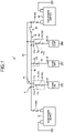
- FIG. 1 is a block diagram illustrating a configuration of the power supply device 1 according to the embodiment.
- FIG. 2 is a graph illustrating a voltage of power supplied from the power supply device 1 according to the embodiment.
- the power supply device 1 supplies power to a load unit 2.
- the power supply device 1 is mounted on a vehicle, and supplies power to the load unit 2 of the vehicle.
- the power supply device 1 includes a main power supply 10, a sub-power supply 20, a fusing unit 30, a main power supply path 40, a sub-power supply path 50, a power supply selector switch 60, a load selector switch group 70, and a load branch unit 80.
- the main power supply 10 supplies power to the load unit 2.
- the main power supply 10 is, for example, a storage battery capable of charging and discharging DC power, and functions as a main power supply.
- the main power supply 10 is connected to a power supply unit (not illustrated) such as a generator or a charger, and charges power supplied from the power supply unit.
- the main power supply 10 is connected via the main power supply path 40 to the load unit 2, and supplies the charged power to the load unit 2 via the main power supply path 40.
- the main power supply 10 has a positive electrode connected via a fuse 31 to the main power supply path 40 and a negative electrode connected to the ground.
- the sub-power supply 20 is a power supply different from the main power supply 10 and supplies power to the load unit 2.
- the sub-power supply 20 is, for example, a storage battery capable of charging and discharging DC power, and functions as a sub-power supply.
- the sub-power supply 20 has a positive electrode connected via the main power supply path 40 to the positive electrode of the main power supply 10, and charges the power supplied from the main power supply path 40.
- the sub-power supply 20 is connected via the sub-power supply path 50 to the load unit 2, and supplies the charged power to the load unit 2 via the sub-power supply path 50.
- the sub-power supply 20 has a positive electrode connected via the fuse 32 to the sub-power supply path 50 and a negative electrode connected to the ground.
- the fusing unit 30 is configured to fuse when an overcurrent flows due to an abnormality such as a short circuit, and interrupt the current.
- the fusing unit 30 is configured by including fuses 31 to 35.
- the fuse 31 is disposed between the positive electrode of the main power supply 10 and the main power supply path 40. When an overcurrent flows from the main power supply 10 to the main power supply path 40, the fuse 31 fuses to interrupt the current.
- the fuse 32 is disposed between the positive electrode of the sub-power supply 20 and the sub-power supply path 50. When an overcurrent flows from the sub-power supply 20 to the sub-power supply path 50, the fuse 32 fuses to interrupt the current.
- the fuse 33 is disposed between the main power supply path 40 and the sub-power supply path 50, and a load unit 2a.
- the fuse 33 When an overcurrent flows from the main power supply path 40 or the sub-power supply path 50 to the load unit 2a, the fuse 33 fuses to interrupt the current.
- the fuse 34 is disposed between the main power supply path 40 and the sub-power supply path 50, and a load unit 2b. When an overcurrent flows from the main power supply path 40 or the sub-power supply path 50 to the load unit 2b, the fuse 34 fuses to interrupt the current.
- the fuse 35 is disposed between the main power supply path 40 and a load unit 2c. When an overcurrent flows from the main power supply path 40 to the load unit 2c, the fuse 35 fuses to interrupt the current.
- the main power supply path 40 is a conductive line through which a current flows, and constitutes a trunk line that is a main power supply line as a power supply backbone of a vehicle.
- the main power supply path 40 is formed of, for example, a wiring material having a round bar conductor or a stranded wire conductor, or a strip-shaped flat conductor having a flat cross-section, these wiring material and strip-shaped flat conductor having a predetermined current capacity.
- the main power supply path 40 is connected via the fuse 31 to the positive electrode of the main power supply 10 at one side and is connected via the power supply selector switch 60 and the fuse 32 to the positive electrode of the sub-power supply 20 at the other side. Further, the load unit 2 is connected via the load selector switch group 70 to the main power supply path 40 at a branch part branching from the main power supply path 40. The main power supply path 40 outputs power supplied from the main power supply 10 to the sub-power supply 20 and the load unit 2.
- the sub-power supply path 50 is a conductive line through which a current flows, and constitutes a trunk line that is a main power supply line as a power supply backbone of a vehicle.
- the sub-power supply path 50 is formed of, for example, a wiring material having a round bar conductor or a stranded wire conductor, or a strip-shaped flat conductor having a flat cross-section, these wiring material and strip-shaped flat conductor having a predetermined current capacity.
- the sub-power supply path 50 is a power supply path different from the main power supply path 40, and is connected via the fuse 32 to the positive electrode of the sub-power supply 20 at one side and is connected via the load selector switch group 70 to the load unit 2 at the other side. Further, the load unit 2 is connected via the load selector switch group 70 to the sub-power supply path 50 at a branch part branching from the sub-power supply path 50.
- the sub-power supply path 50 outputs power supplied from the sub-power supply 20 to the load unit 2.
- the power supply selector switch 60 is a switch that is turned on to turn on electricity and is turned off to interrupt a current.
- the power supply selector switch 60 is disposed between a load selector switch 72 on a side of the sub-power supply 20 and the sub-power supply 20 in the main power supply path 40.
- the power supply selector switch 60 is on-off controlled by a switch control unit (not illustrated) and switches the power supply to the load unit 2 to one of the main power supply 10 and the sub-power supply 20.
- the switch control unit determines an abnormality (short circuit) in the main power supply path 40 based on a result of detecting the voltage of the main power supply path 40.
- the switch control unit determines that the main power supply path 40 is normal when the voltage of the main power supply path 40 is equal to or higher than a predetermined reference voltage, and determines that the main power supply path 40 is abnormal (short circuit) when the voltage of the main power supply path 40 is lower than the reference voltage.
- the power supply selector switch 60 When the power supply selector switch 60 is turned on by the switch control unit, power is supplied from the main power supply 10 via the main power supply path 40 to the load unit 2. When the power supply selector switch 60 is turned off by the switch control unit, power is supplied from the sub-power supply 20 via the sub-power supply path 50 to the load unit 2. That is, the power supply selector switch 60 is switched between a first state where power can be supplied from the main power supply 10 via the main power supply path 40 to the load unit 2 and a second state where power can be supplied from the sub-power supply 20 via the sub-power supply path 50 to the load unit 2.
- the load selector switch group 70 is a switch group that is turned on to turn on electricity and is turned off to interrupt a current.
- the load selector switch group 70 is disposed between the main power supply path 40 and the sub-power supply path 50, and the load unit 2.
- the load selector switch group 70 performs switching so as to connect one of the main power supply path 40 and the sub-power supply path 50 to the load unit 2 and to disconnect the other of the main power supply path 40 and the sub-power supply paths 50 from the load unit 2, according to switching of the power supply selector switch 60.
- the load selector switch group 70 includes, for example, a voltage detector (not illustrated) that detects a main power supply voltage that is a voltage applied from the main power supply 10 to the main power supply path 40 and a sub-power supply voltage that is a voltage applied from the sub-power supply 20 to the sub-power supply path 50.
- the load selector switch group 70 switches the connection of the load unit 2 based on a result of detection of the voltage detector. For example, when the main power supply voltage is higher than the sub-power supply voltage, the load selector switch group 70 performs switching so as to connect the main power supply path 40 to the load unit 2 and disconnect the sub-power supply path 50 from the load unit 2. On the other hand, when the sub-power supply voltage is higher than the main power supply voltage, the load selector switch group 70 performs switching so as to connect the sub-power supply path 50 to the load unit 2 and disconnect the main power supply path 40 from the load unit 2.
- the load selector switch group 70 keeps a state where the power supply voltage is decreased until the fusing unit 30 is fused, because a short circuit probably occurs on a downstream side of a branch part of the power supply path.
- the load selector switch group 70 is configured by including a plurality of load selector switches 71 and 72.
- the load selector switch 71 is disposed between the main power supply path 40 and the sub-power supply path 50, and the load unit 2a.
- the load selector switch 71 includes a main terminal 71a connected to the main power supply path 40, a sub-terminal 71b connected to the sub-power supply path 50, and one load terminal 71c connected to the load unit 2.
- the load selector switch 71 connects the one load terminal 71c to one of the main terminal 71a and the sub-terminal 71b and does not connect the one load terminal 71c to the other of the main terminal 71a and the sub-terminals 71b, based on a main power supply voltage and a sub-power supply voltage.
- the load selector switch 71 connects the load terminal 71c to the main terminal 71a and does not connect the load terminal 71c to the sub-terminal 71b. Consequently, power can be supplied from the main power supply 10 via the main power supply path 40 to the load unit 2a, and power cannot be supplied from the sub-power supply 20 via the sub-power supply path 50 to the load unit 2a.
- the load selector switch 71 connects the load terminal 71c to the sub-terminal 71b and does not connect the load terminal 71c to the main terminal 71a. Consequently, power can be supplied from the sub-power supply 20 via the sub-power supply path 50 to the load unit 2a, and power cannot be supplied from the main power supply 10 via the main power supply path 40 to the load unit 2a.
- the load selector switch 72 has a similar configuration to the load selector switch 71 described above, and is disposed between the main power supply path 40 and the sub-power supply path 50, and the load unit 2b.
- the load selector switch 72 includes a main terminal 72a connected to the main power supply path 40, a sub-terminal 72b connected to the sub-power supply path 50, and one load terminal 72c connected to the load unit 2.
- the load selector switch 72 connects the one load terminal 72c to one of the main terminal 72a and the sub-terminal 72b and does not connect the one load terminal 72c to the other of the main terminal 72a and the sub-terminals 72b, based on a main power supply voltage and a sub-power supply voltage.
- the load selector switch 72 connects the load terminal 72c to the main terminal 72a and does not connect the load terminal 72c to the sub-terminal 72b. Consequently, power can be supplied from the main power supply 10 via the main power supply path 40 to the load unit 2b, and power cannot be supplied from the sub-power supply 20 via the sub-power supply path 50 to the load unit 2b.
- the load selector switch 72 connects the load terminal 72c to the sub-terminal 72b and does not connect the load terminal 72c to the main terminal 72a. Consequently, power can be supplied from the sub-power supply 20 via the sub-power supply path 50 to the load unit 2b, and power cannot be supplied from the main power supply 10 via the main power supply path 40 to the load unit 2b.
- the load branch unit 80 is a unit that connects the load unit 2c to the main power supply path 40 via the fuse 35.
- the load branch unit 80 does not include the load selector switches 71, 72 described above. That is, the load branch unit 80 connects the load unit 2c to the main power supply path 40 without via the load selector switches 71, 72.
- the power supply device 1 switches the power supply selector switch 60 to a first state where power can be supplied from the main power supply 10 via the main power supply path 40 to the load unit 2, and the load selector switch group 70 performs switching so as to connect the main power supply path 40 to the load unit 2 and disconnect the sub-power supply path 50 from the load unit 2.
- the power supply device 1 switches the power supply selector switch 60 to a second state where power can be supplied from the sub-power supply 20 via the sub-power supply path 50 to the load unit 2, and the load selector switch group 70 performs switching so as to connect the sub-power supply path 50 to the load unit 2 and disconnect the main power supply path 40 from the load unit 2.
- the power supply device 1 as illustrated in FIG.
- a voltage VB at a position B (position on side of sub-power supply 20) on the main power supply path 40 is substantially zero at the time point t1
- a voltage VA at a position A (position on side of main power supply 10) on the main power supply path 40 gradually decreases to zero from the time point t1 to a time point t2 when a power supply is interrupted.
- a voltage VA1 at a position A1 on the sub-power supply path 50 temporarily decreases after the time point t1 due to the short circuit, but immediately returns to the original voltage, and power is supplied via the sub-power supply path 50 to the load unit 2.
- the power supply device 1 includes the main power supply 10, the sub-power supply 20, the main power supply path 40, the sub-power supply path 50, the power supply selector switch 60, and the load selector switch group 70.
- the main power supply 10 supplies power to the load unit 2.
- the sub-power supply 20 is a power supply different from the main power supply 10 and supplies power to the load unit 2.
- the main power supply path 40 is connected to the main power supply 10.
- the sub-power supply path 50 is a power supply path different from the main power supply path 40 and is connected to the sub-power supply 20.
- the power supply selector switch 60 is switched between a first state where power can be supplied from the main power supply 10 via the main power supply path 40 to the load unit 2 and a second state where power can be supplied from the sub-power supply 20 via the sub-power supply path 50 to the load unit 2.
- the load selector switch group 70 is disposed between the main power supply path 40 and the sub-power supply path 50, and the load unit 2, and performs switching so as to connect one of the main power supply path 40 and the sub-power supply path 50 to the load unit 2 and to disconnect the other of the main power supply path 40 and the sub-power supply paths 50 from the load unit 2, according to switching of the power supply selector switch 60.
- the power supply device 1 when the main power supply path 40 is short-circuited for example, the power supply device 1 causes the load selector switch group 70 to perform switching so as to disconnect the main power supply path 40 from the load unit 2.
- the power supply can thus be switched before a decrease in a power supply voltage that occurs at the time of the short circuit of the main power supply path 40 affects a normal operation of the load unit 2. Consequently, the power supply device 1 can reduce the influence of the short circuit of the main power supply path 40 on the load unit 2, and as a result, the power supply can be appropriately made redundant.
- the power supply device 1 When the main power supply path 40 is normal, the power supply device 1 switches the power supply selector switch 60 to the first state described above, and the load selector switch group 70 performs switching so as to connect the main power supply path 40 to the load unit 2 and disconnect the sub-power supply path 50 from the load unit 2.
- the power supply device 1 switches the power supply selector switch 60 to the second state described above, and the load selector switch group 70 performs switching so as to connect the sub-power supply path 50 to the load unit 2 and disconnect the main power supply path 40 from the load unit 2.
- the power supply device 1 can reduce the influence of the short circuit of the main power supply path 40 on the load unit 2, and as a result, the power supply can be appropriately made redundant.
- the load selector switch group 70 includes, for example, the main terminal 71a connected to the main power supply path 40, the sub-terminal 71b connected to the sub-power supply path 50, and one load terminal 71c connected to the load unit 2.
- the load selector switch group 70 connects the one load terminal 71c to one of the main terminal 71a and the sub-terminal 71b, and does not connect the one load terminal 71c to the other of the main terminal 71a and the sub-terminal 71b.
- the number of connection lines of the load unit 2 connected to the load terminal 71c can be reduced to one in the power supply device 1 and the load unit 2 does not need to have a redundant connection line as in conventional cases. Connection with the load unit 2 can thus be simplified.
- FIG. 3 is a block diagram illustrating a configuration of a power supply device 1A according to the modification of the embodiment.
- FIG. 4 is a diagram illustrating a voltage of power supplied from the power supply device 1A according to the modification of the embodiment.
- the power supply device 1A according to the modification of the embodiment is different from the power supply device 1 according to the embodiment in that a DC/DC converter 60A is provided instead of the power supply selector switch 60.
- the power supply device 1A includes the main power supply 10, the sub-power supply 20, the fusing unit 30, the main power supply path 40, the sub-power supply path 50, the DC/DC converter 60A, the load selector switch group 70, and the load branch unit 80.
- the DC/DC converter 60A is a transformer that transforms a voltage.
- the DC/DC converter 60A is disposed between the load selector switch 72 on a side of the sub-power supply 20 and the sub-power supply 20 in the main power supply path 40.
- the DC/DC converter 60A is controlled by a converter control unit (not illustrated), switches the power supply to the load unit 2 to one of the main power supply 10 and the sub-power supply 20, and transforms a voltage supplied from the main power supply 10 to the sub-power supply 20.
- the converter control unit determines an abnormality (short circuit) in the main power supply path 40 based on a result of detecting the voltage of the main power supply path 40.
- the converter control unit determines that the main power supply path 40 is normal when the voltage of the main power supply path 40 is equal to or higher than a predetermined reference voltage, and determines that the main power supply path 40 is abnormal (short circuit) when the voltage of the main power supply path 40 is lower than the reference voltage.
- the converter control unit determines that the DC/DC converter 60A is normal, power is supplied from the main power supply 10 via the main power supply path 40 to the load unit 2.
- the converter control unit determines that the DC/DC converter 60A is abnormal, power is supplied from the sub-power supply 20 via the sub-power supply path 50 to the load unit 2. That is, the DC/DC converter 60A is switched between a first state where power can be supplied from the main power supply 10 via the main power supply path 40 to the load unit 2 and a second state where power can be supplied from the sub-power supply 20 via the sub-power supply path 50 to the load unit 2.
- a voltage Vb at a position b (position on side of sub-power supply 20) on the main power supply path 40 is substantially zero at the time point t1
- a voltage Va at a position a (position on side of main power supply 10) on the main power supply path 40 gradually decreases to zero from the time point t1 to the time point t2 when a power supply is interrupted.
- the power supply device 1A transforms (boosts) the voltage of power supplied from the main power supply 10 and supplies the transformed voltage to the sub-power supply 20, it is possible to prevent a voltage Va1 at a position a1 on the sub-power supply path 50 from decreasing after the time point t1 due to the influence of the short circuit, and a constant voltage can thus be kept.
- the power supply device 1A is configured by including the DC/DC converter 60A that transforms the voltage of DC power.
- the DC/DC converter 60A transforms the voltage of power supplied from the main power supply 10 and supplies the transformed voltage to the sub-power supply 20.
- the power supply device 1A can prevent a voltage from decreasing due to the influence of the short circuit of the main power supply path 40, and keep a constant voltage.
- the present invention is not limited to this configuration example, and other switch configurations may be used.
- the load selector switch group 70 may switch the connection of the load unit 2 based on a result of comparing the main power supply voltage with a predetermined reference voltage.
- the reference voltage is a voltage that affects a normal operation of the load unit 2.
- the load selector switch group 70 performs switching so as to connect the main power supply path 40 to the load unit 2 and disconnect the sub-power supply path 50 from the load unit 2.
- the load selector switch group 70 performs switching so as to connect the sub-power supply path 50 to the load unit 2 and disconnect the main power supply path 40 from the load unit 2.
- the load selector switch group 70 may include a current detector (not illustrated) that detects a main power supply current that is a current applied from the main power supply 10 to the main power supply path 40 and a sub-power supply current that is a current applied from the sub-power supply 20 to the sub-power supply path 50. In this case, for example, when the sub-power supply current is equal to or more than a predetermined reference current (allowable current of electric wire), the load selector switch group 70 does not switch to the sub-power supply path 50.
- the power supply device 1 may include a protector that prevents an electric wire from burning at a connection part of the main power supply 10 and the main power supply path 40, a branch part of the main power supply path 40, or the like when a short circuit occurs.
- the power supply device includes the load supply path selector that performs switching so as to connect one of the main power supply path and the sub-power supply path to the load unit and disconnect the other of the main power supply path and the sub-power supply path from the load unit. Consequently, it is possible to reduce the influence of a ground fault on the load unit when the ground fault occurs, and as a result, a power supply can be appropriately made redundant.
Landscapes
- Engineering & Computer Science (AREA)
- Power Engineering (AREA)
- Business, Economics & Management (AREA)
- Emergency Management (AREA)
- Mechanical Engineering (AREA)
- Direct Current Feeding And Distribution (AREA)
- Charge And Discharge Circuits For Batteries Or The Like (AREA)
Claims (3)
- Stromversorgungsvorrichtung (1), umfassend:eine Hauptstromversorgung (10), die eine Lasteinheit (2) mit Strom versorgt,eine Unter-Stromversorgung (20), die eine Stromversorgung ist, die sich von der Hauptstromversorgung (10) unterscheidet und die die Lasteinheit (2) mit Strom versorgt;einen Haupt-Stromversorgungsweg (40), der mit der Hauptstromversorgung (10) verbunden ist;ein Unter-Stromversorgungsweg (50), der ein Stromversorgungsweg ist, der sich von dem Haupt-Stromversorgungsweg (40) unterscheidet und der mit der Unter-Stromversorgung (20) verbunden ist;ein Lastversorgungswegwähler (70), der zwischen dem Haupt-Stromversorgungsweg (40) und dem Unter-Stromversorgungsweg (50), und der Lasteinheit (2) angeordnet ist, und Schalten durchführt, um einen des Haupt-Stromversorgungswegs (40) und des Unter-Stromversorgungswegs (50) mit der Lasteinheit (2) zu verbinden und den anderen des Haupt-Stromversorgungswegs (40) und des Unter-Stromversorgungswegs (50) von der Lasteinheit (2) zu trennen, wobeider Lastversorgungswegwähler (70) einen Hauptanschluss (71a, 72a), der mit dem Haupt-Stromversorgungsweg (40) verbunden ist, einen Unteranschluss (71b, 72b), der mit dem Unter-Stromversorgungsweg (50) verbunden ist, und einen Lastanschluss (71c, 72c), der mit der Lasteinheit (2) verbunden ist, enthält, und der eine Lastanschluss (71c, 72c) mit einem des Hauptanschlusses (71a, 72a) und des Unteranschlusses (71b, 72b) verbunden ist, und der eine Lastanschluss (71c, 72c) nicht mit dem anderen des Hauptanschlusses (71a, 72a) und des Unteranschlusses (71b, 72b) verbunden ist;gekennzeichnet durcheinen Stromversorgungs-Wählschalter (60), der zwischen dem Lastwegwähler (70) auf einer Seite der Unter-Stromversorgung (20) und der Unter-Stromversorgung (20) angeordnet ist, wobeiwenn der Stromversorgungs-Wählschalter (60) eingeschaltet ist, Strom von der Hauptstromversorgung (10) über den Haupt-Stromversorgungsweg (40) geliefert wird, und wenn der Stromversorgungs-Wählschalter (60) ausgeschaltet ist, Strom von der Unter-Stromversorgung (20) über den Unter-Stromversorgungsweg (50) an die Lasteinheit (2) geliefert wird, undder Stromversorgungswegwähler (70) Schalten entsprechend dem Schalten des Stromversorgungs-Wählschalters (60) durchführt.
- Stromversorgungsvorrichtung (1) nach Anspruch 1, wobeiwenn der Haupt-Stromversorgungsweg (40) normal ist, der Stromversorgungs-Wählschalter (60) eingeschaltet ist, und der Stromversorgungswegwähler (70) Schalten durchführt, um den Haupt-Stromversorgungsweg (40) mit der Lasteinheit (2) zu verbinden und den Unter-Stromversorgungsweg (50) von der Lasteinheit (2) zu trennen, undwenn der Haupt-Stromversorgungsweg (40) abnormal ist, der Stromversorgungs-Wählschalter (60) ausgeschaltet ist, und der Stromversorgungswegwähler (70) Schalten durchführt, um den Unter-Stromversorgungsweg (50) mit der Lasteinheit (2) zu verbinden und den Haupt-Stromversorgungsweg (40) von der Lasteinheit (2) zu trennen.
- Stromversorgungsvorrichtung (1A), umfassend:eine Hauptstromversorgung (10), die eine Lasteinheit (2) mit Strom versorgt,eine Unter-Stromversorgung (20), die eine Stromversorgung ist, die sich von der Hauptstromversorgung (10) unterscheidet und die die Lasteinheit (2) mit Strom versorgt;einen Haupt-Stromversorgungsweg (40), der mit der Hauptstromversorgung (10) verbunden ist;ein Unter-Stromversorgungsweg (50), der ein Stromversorgungsweg ist, der sich von dem Haupt-Stromversorgungsweg (40) unterscheidet und der mit der Unter-Stromversorgung (20) verbunden ist;ein Lastversorgungswegwähler (70), der zwischen dem Haupt-Stromversorgungsweg (40) und dem Unter-Stromversorgungsweg (50), und der Lasteinheit (2) angeordnet ist, und Schalten durchführt, um einen des Haupt-Stromversorgungswegs (40) und des Unter-Stromversorgungswegs (50) mit der Lasteinheit (2) zu verbinden und den anderen des Haupt-Stromversorgungswegs (40) und des Unter-Stromversorgungswegs (50) von der Lasteinheit (2) zu trennen, wobeider Lastversorgungswegwähler (70) einen Hauptanschluss (71a, 72a), der mit dem Haupt-Stromversorgungsweg (40) verbunden ist, einen Unteranschluss (71b, 72b), der mit dem Unter-Stromversorgungsweg (50) verbunden ist, und einen Lastanschluss (71c, 72c), der mit der Lasteinheit (2) verbunden ist, enthält, und der eine Lastanschluss (71c, 72c) mit einem des Hauptanschlusses (71a, 72a) und des Unteranschlusses (71b, 72b) verbunden ist, und der eine Lastanschluss (71c, 72c) nicht mit dem anderen des Hauptanschlusses (71a, 72a) und des Unteranschlusses (71b, 72b) verbunden ist;gekennzeichnet durcheinen DC/DC-Wandler (60A), der zwischen dem Lastwegwähler (70) auf einer Seite der Unter-Stromversorgung (10) und der Unter-Stromversorgung (20) angeordnet ist und eine Spannung eines DC-Stroms wandelt, wobeider DC/DC-Wandler (60A) die Stromversorgung zu der Lasteinheit (2) schaltet auf eine der Hauptstromversorgung (10) und der Unter-Stromversorgung (2) und eine Spannung eines Stroms, der von der Hauptstromversorgung (10) geliefert wird, wandelt und eine gewandelte Spannung an die Unter-Stromversorgung (20) liefert, undder Stromversorgungswegwähler (70) Schalten entsprechend dem Schalten des DC/DC-Wandlers (60A) durchführt.
Applications Claiming Priority (1)
| Application Number | Priority Date | Filing Date | Title |
|---|---|---|---|
| JP2019148317A JP2021029093A (ja) | 2019-08-13 | 2019-08-13 | 電源装置 |
Publications (2)
| Publication Number | Publication Date |
|---|---|
| EP3780331A1 EP3780331A1 (de) | 2021-02-17 |
| EP3780331B1 true EP3780331B1 (de) | 2022-09-14 |
Family
ID=71527609
Family Applications (1)
| Application Number | Title | Priority Date | Filing Date |
|---|---|---|---|
| EP20184617.7A Active EP3780331B1 (de) | 2019-08-13 | 2020-07-08 | Stromversorgungsvorrichtung |
Country Status (4)
| Country | Link |
|---|---|
| US (1) | US11114888B2 (de) |
| EP (1) | EP3780331B1 (de) |
| JP (1) | JP2021029093A (de) |
| CN (1) | CN112398189A (de) |
Cited By (1)
| Publication number | Priority date | Publication date | Assignee | Title |
|---|---|---|---|---|
| EP4604342A1 (de) * | 2024-02-13 | 2025-08-20 | LEONI Bordnetz-Systeme GmbH | Redundante energieversorgung für elektrische verbraucher |
Families Citing this family (6)
| Publication number | Priority date | Publication date | Assignee | Title |
|---|---|---|---|---|
| JP6926132B2 (ja) * | 2019-01-23 | 2021-08-25 | 矢崎総業株式会社 | 保護回路ユニット及び車両用電源装置 |
| JP7579170B2 (ja) * | 2021-02-16 | 2024-11-07 | 本田技研工業株式会社 | 電力供給回路 |
| JP7517201B2 (ja) | 2021-02-25 | 2024-07-17 | 株式会社デンソー | ペダル装置 |
| CN115207894A (zh) * | 2021-04-12 | 2022-10-18 | 合肥一通电子技术有限公司 | 一种系统电源 |
| JP7740937B2 (ja) * | 2021-09-01 | 2025-09-17 | 古河電気工業株式会社 | 電源システム |
| JP7650610B2 (ja) * | 2023-01-23 | 2025-03-25 | 矢崎総業株式会社 | 電源装置 |
Family Cites Families (16)
| Publication number | Priority date | Publication date | Assignee | Title |
|---|---|---|---|---|
| JP3687409B2 (ja) * | 1999-04-26 | 2005-08-24 | トヨタ自動車株式会社 | 車両用電源供給制御装置 |
| JP2008072880A (ja) * | 2006-09-15 | 2008-03-27 | Toyota Motor Corp | 電源システム |
| DE102013214835A1 (de) * | 2013-07-30 | 2015-02-05 | Robert Bosch Gmbh | Überspannungsschutz für ein Mehrspannungsbordnetz |
| JP2015217734A (ja) * | 2014-05-15 | 2015-12-07 | 株式会社オートネットワーク技術研究所 | 自動車の電源装置 |
| DE102015101235A1 (de) * | 2015-01-28 | 2016-07-28 | Bayerische Motoren Werke Aktiengesellschaft | Elektrisches Energieversorgungssystem für ein Fahrzeug und Verfahren zum Betreiben eines elektrischen Energieversorgungssystems |
| JP6569570B2 (ja) * | 2016-03-15 | 2019-09-04 | 株式会社オートネットワーク技術研究所 | 電源装置 |
| JP6412039B2 (ja) | 2016-03-17 | 2018-10-24 | 矢崎総業株式会社 | 電力中継器 |
| JP2017195653A (ja) * | 2016-04-18 | 2017-10-26 | 株式会社オートネットワーク技術研究所 | 車載電源用のスイッチ装置および車載用電源システム |
| JP6690396B2 (ja) * | 2016-05-13 | 2020-04-28 | 株式会社オートネットワーク技術研究所 | リレー装置 |
| JP6610439B2 (ja) * | 2016-05-31 | 2019-11-27 | 株式会社オートネットワーク技術研究所 | 電源装置 |
| JP6825253B2 (ja) * | 2016-07-20 | 2021-02-03 | 株式会社デンソー | 制御装置、及び電源システム |
| JP6628699B2 (ja) * | 2016-08-02 | 2020-01-15 | 株式会社デンソーテン | 給電制御装置および給電制御システム |
| JP6662282B2 (ja) * | 2016-12-20 | 2020-03-11 | 株式会社デンソー | 電源システム |
| JP6652103B2 (ja) * | 2017-04-19 | 2020-02-19 | 株式会社デンソー | 車両の自動運転制御システム |
| JP6546617B2 (ja) * | 2017-05-18 | 2019-07-17 | 矢崎総業株式会社 | 電力分配システム |
| JP6930505B2 (ja) * | 2017-09-22 | 2021-09-01 | 株式会社デンソー | 電源システム |
-
2019
- 2019-08-13 JP JP2019148317A patent/JP2021029093A/ja not_active Abandoned
-
2020
- 2020-07-08 EP EP20184617.7A patent/EP3780331B1/de active Active
- 2020-07-09 CN CN202010658218.1A patent/CN112398189A/zh not_active Withdrawn
- 2020-08-05 US US16/986,213 patent/US11114888B2/en not_active Expired - Fee Related
Cited By (1)
| Publication number | Priority date | Publication date | Assignee | Title |
|---|---|---|---|---|
| EP4604342A1 (de) * | 2024-02-13 | 2025-08-20 | LEONI Bordnetz-Systeme GmbH | Redundante energieversorgung für elektrische verbraucher |
Also Published As
| Publication number | Publication date |
|---|---|
| EP3780331A1 (de) | 2021-02-17 |
| CN112398189A (zh) | 2021-02-23 |
| US20210050740A1 (en) | 2021-02-18 |
| US11114888B2 (en) | 2021-09-07 |
| JP2021029093A (ja) | 2021-02-25 |
Similar Documents
| Publication | Publication Date | Title |
|---|---|---|
| EP3780331B1 (de) | Stromversorgungsvorrichtung | |
| US11677232B2 (en) | Quick battery disconnect system for high current circuits | |
| JP6690396B2 (ja) | リレー装置 | |
| JP6087675B2 (ja) | 電池モジュール | |
| USRE50397E1 (en) | Battery pack | |
| KR102454579B1 (ko) | 전기적 온보드 전력 공급 시스템 및 이러한 온보드 전력 공급 시스템을 작동하기 위한 방법 | |
| US10442376B2 (en) | Vehicle power supply control device | |
| US11909253B2 (en) | Power supply circuit | |
| JP2019140718A (ja) | 電源システム | |
| KR101786347B1 (ko) | 점프 스타트를 위한 차량의 전력 시스템 | |
| US11942817B2 (en) | Power supply circuit | |
| CN111095719A (zh) | 蓄电池装置 | |
| US20230368991A1 (en) | Dc circuit switching apparatus | |
| US12160126B2 (en) | In-vehicle battery system | |
| JP2006223050A (ja) | 電力供給システム | |
| US20250260246A1 (en) | Control unit for controlling the power of at least one battery, aircraft comprising said control unit, and corresponding control method | |
| JP7667663B2 (ja) | 電力装置及びその制御方法 | |
| US20250105636A1 (en) | Power distribution device | |
| JP7819312B2 (ja) | 車載用のバックアップ制御装置 | |
| KR20260054944A (ko) | Pra 시스템 | |
| JP2020054080A (ja) | 電力供給装置、車両および電力供給制御装置 | |
| JP7200915B2 (ja) | 蓄電システム | |
| KR20210051607A (ko) | 배터리 보호 시스템 |
Legal Events
| Date | Code | Title | Description |
|---|---|---|---|
| PUAI | Public reference made under article 153(3) epc to a published international application that has entered the european phase |
Free format text: ORIGINAL CODE: 0009012 |
|
| STAA | Information on the status of an ep patent application or granted ep patent |
Free format text: STATUS: REQUEST FOR EXAMINATION WAS MADE |
|
| 17P | Request for examination filed |
Effective date: 20200708 |
|
| AK | Designated contracting states |
Kind code of ref document: A1 Designated state(s): AL AT BE BG CH CY CZ DE DK EE ES FI FR GB GR HR HU IE IS IT LI LT LU LV MC MK MT NL NO PL PT RO RS SE SI SK SM TR |
|
| AX | Request for extension of the european patent |
Extension state: BA ME |
|
| STAA | Information on the status of an ep patent application or granted ep patent |
Free format text: STATUS: EXAMINATION IS IN PROGRESS |
|
| 17Q | First examination report despatched |
Effective date: 20220209 |
|
| REG | Reference to a national code |
Ref country code: DE Ref legal event code: R079 Ref document number: 602020005095 Country of ref document: DE Free format text: PREVIOUS MAIN CLASS: H02J0007140000 Ipc: H02H0007260000 |
|
| GRAP | Despatch of communication of intention to grant a patent |
Free format text: ORIGINAL CODE: EPIDOSNIGR1 |
|
| STAA | Information on the status of an ep patent application or granted ep patent |
Free format text: STATUS: GRANT OF PATENT IS INTENDED |
|
| RIC1 | Information provided on ipc code assigned before grant |
Ipc: B60R 16/03 20060101ALI20220531BHEP Ipc: H02J 7/34 20060101ALI20220531BHEP Ipc: H02J 7/14 20060101ALI20220531BHEP Ipc: H02J 1/10 20060101ALI20220531BHEP Ipc: H02J 1/08 20060101ALI20220531BHEP Ipc: H02H 3/05 20060101ALI20220531BHEP Ipc: H02H 7/26 20060101AFI20220531BHEP |
|
| INTG | Intention to grant announced |
Effective date: 20220628 |
|
| GRAS | Grant fee paid |
Free format text: ORIGINAL CODE: EPIDOSNIGR3 |
|
| GRAA | (expected) grant |
Free format text: ORIGINAL CODE: 0009210 |
|
| STAA | Information on the status of an ep patent application or granted ep patent |
Free format text: STATUS: THE PATENT HAS BEEN GRANTED |
|
| AK | Designated contracting states |
Kind code of ref document: B1 Designated state(s): AL AT BE BG CH CY CZ DE DK EE ES FI FR GB GR HR HU IE IS IT LI LT LU LV MC MK MT NL NO PL PT RO RS SE SI SK SM TR |
|
| REG | Reference to a national code |
Ref country code: GB Ref legal event code: FG4D |
|
| REG | Reference to a national code |
Ref country code: CH Ref legal event code: EP |
|
| REG | Reference to a national code |
Ref country code: DE Ref legal event code: R096 Ref document number: 602020005095 Country of ref document: DE |
|
| REG | Reference to a national code |
Ref country code: IE Ref legal event code: FG4D |
|
| REG | Reference to a national code |
Ref country code: AT Ref legal event code: REF Ref document number: 1519284 Country of ref document: AT Kind code of ref document: T Effective date: 20221015 |
|
| REG | Reference to a national code |
Ref country code: LT Ref legal event code: MG9D |
|
| REG | Reference to a national code |
Ref country code: NL Ref legal event code: MP Effective date: 20220914 |
|
| PG25 | Lapsed in a contracting state [announced via postgrant information from national office to epo] |
Ref country code: SE Free format text: LAPSE BECAUSE OF FAILURE TO SUBMIT A TRANSLATION OF THE DESCRIPTION OR TO PAY THE FEE WITHIN THE PRESCRIBED TIME-LIMIT Effective date: 20220914 Ref country code: RS Free format text: LAPSE BECAUSE OF FAILURE TO SUBMIT A TRANSLATION OF THE DESCRIPTION OR TO PAY THE FEE WITHIN THE PRESCRIBED TIME-LIMIT Effective date: 20220914 Ref country code: NO Free format text: LAPSE BECAUSE OF FAILURE TO SUBMIT A TRANSLATION OF THE DESCRIPTION OR TO PAY THE FEE WITHIN THE PRESCRIBED TIME-LIMIT Effective date: 20221214 Ref country code: LV Free format text: LAPSE BECAUSE OF FAILURE TO SUBMIT A TRANSLATION OF THE DESCRIPTION OR TO PAY THE FEE WITHIN THE PRESCRIBED TIME-LIMIT Effective date: 20220914 Ref country code: LT Free format text: LAPSE BECAUSE OF FAILURE TO SUBMIT A TRANSLATION OF THE DESCRIPTION OR TO PAY THE FEE WITHIN THE PRESCRIBED TIME-LIMIT Effective date: 20220914 Ref country code: FI Free format text: LAPSE BECAUSE OF FAILURE TO SUBMIT A TRANSLATION OF THE DESCRIPTION OR TO PAY THE FEE WITHIN THE PRESCRIBED TIME-LIMIT Effective date: 20220914 |
|
| REG | Reference to a national code |
Ref country code: AT Ref legal event code: MK05 Ref document number: 1519284 Country of ref document: AT Kind code of ref document: T Effective date: 20220914 |
|
| PG25 | Lapsed in a contracting state [announced via postgrant information from national office to epo] |
Ref country code: HR Free format text: LAPSE BECAUSE OF FAILURE TO SUBMIT A TRANSLATION OF THE DESCRIPTION OR TO PAY THE FEE WITHIN THE PRESCRIBED TIME-LIMIT Effective date: 20220914 Ref country code: GR Free format text: LAPSE BECAUSE OF FAILURE TO SUBMIT A TRANSLATION OF THE DESCRIPTION OR TO PAY THE FEE WITHIN THE PRESCRIBED TIME-LIMIT Effective date: 20221215 |
|
| PG25 | Lapsed in a contracting state [announced via postgrant information from national office to epo] |
Ref country code: SM Free format text: LAPSE BECAUSE OF FAILURE TO SUBMIT A TRANSLATION OF THE DESCRIPTION OR TO PAY THE FEE WITHIN THE PRESCRIBED TIME-LIMIT Effective date: 20220914 Ref country code: RO Free format text: LAPSE BECAUSE OF FAILURE TO SUBMIT A TRANSLATION OF THE DESCRIPTION OR TO PAY THE FEE WITHIN THE PRESCRIBED TIME-LIMIT Effective date: 20220914 Ref country code: PT Free format text: LAPSE BECAUSE OF FAILURE TO SUBMIT A TRANSLATION OF THE DESCRIPTION OR TO PAY THE FEE WITHIN THE PRESCRIBED TIME-LIMIT Effective date: 20230116 Ref country code: ES Free format text: LAPSE BECAUSE OF FAILURE TO SUBMIT A TRANSLATION OF THE DESCRIPTION OR TO PAY THE FEE WITHIN THE PRESCRIBED TIME-LIMIT Effective date: 20220914 Ref country code: CZ Free format text: LAPSE BECAUSE OF FAILURE TO SUBMIT A TRANSLATION OF THE DESCRIPTION OR TO PAY THE FEE WITHIN THE PRESCRIBED TIME-LIMIT Effective date: 20220914 Ref country code: AT Free format text: LAPSE BECAUSE OF FAILURE TO SUBMIT A TRANSLATION OF THE DESCRIPTION OR TO PAY THE FEE WITHIN THE PRESCRIBED TIME-LIMIT Effective date: 20220914 |
|
| PG25 | Lapsed in a contracting state [announced via postgrant information from national office to epo] |
Ref country code: SK Free format text: LAPSE BECAUSE OF FAILURE TO SUBMIT A TRANSLATION OF THE DESCRIPTION OR TO PAY THE FEE WITHIN THE PRESCRIBED TIME-LIMIT Effective date: 20220914 Ref country code: PL Free format text: LAPSE BECAUSE OF FAILURE TO SUBMIT A TRANSLATION OF THE DESCRIPTION OR TO PAY THE FEE WITHIN THE PRESCRIBED TIME-LIMIT Effective date: 20220914 Ref country code: IS Free format text: LAPSE BECAUSE OF FAILURE TO SUBMIT A TRANSLATION OF THE DESCRIPTION OR TO PAY THE FEE WITHIN THE PRESCRIBED TIME-LIMIT Effective date: 20230114 Ref country code: EE Free format text: LAPSE BECAUSE OF FAILURE TO SUBMIT A TRANSLATION OF THE DESCRIPTION OR TO PAY THE FEE WITHIN THE PRESCRIBED TIME-LIMIT Effective date: 20220914 |
|
| REG | Reference to a national code |
Ref country code: DE Ref legal event code: R097 Ref document number: 602020005095 Country of ref document: DE |
|
| PG25 | Lapsed in a contracting state [announced via postgrant information from national office to epo] |
Ref country code: NL Free format text: LAPSE BECAUSE OF FAILURE TO SUBMIT A TRANSLATION OF THE DESCRIPTION OR TO PAY THE FEE WITHIN THE PRESCRIBED TIME-LIMIT Effective date: 20220914 Ref country code: AL Free format text: LAPSE BECAUSE OF FAILURE TO SUBMIT A TRANSLATION OF THE DESCRIPTION OR TO PAY THE FEE WITHIN THE PRESCRIBED TIME-LIMIT Effective date: 20220914 |
|
| PLBE | No opposition filed within time limit |
Free format text: ORIGINAL CODE: 0009261 |
|
| STAA | Information on the status of an ep patent application or granted ep patent |
Free format text: STATUS: NO OPPOSITION FILED WITHIN TIME LIMIT |
|
| PG25 | Lapsed in a contracting state [announced via postgrant information from national office to epo] |
Ref country code: DK Free format text: LAPSE BECAUSE OF FAILURE TO SUBMIT A TRANSLATION OF THE DESCRIPTION OR TO PAY THE FEE WITHIN THE PRESCRIBED TIME-LIMIT Effective date: 20220914 |
|
| 26N | No opposition filed |
Effective date: 20230615 |
|
| PG25 | Lapsed in a contracting state [announced via postgrant information from national office to epo] |
Ref country code: SI Free format text: LAPSE BECAUSE OF FAILURE TO SUBMIT A TRANSLATION OF THE DESCRIPTION OR TO PAY THE FEE WITHIN THE PRESCRIBED TIME-LIMIT Effective date: 20220914 |
|
| PG25 | Lapsed in a contracting state [announced via postgrant information from national office to epo] |
Ref country code: MC Free format text: LAPSE BECAUSE OF FAILURE TO SUBMIT A TRANSLATION OF THE DESCRIPTION OR TO PAY THE FEE WITHIN THE PRESCRIBED TIME-LIMIT Effective date: 20220914 |
|
| PG25 | Lapsed in a contracting state [announced via postgrant information from national office to epo] |
Ref country code: MC Free format text: LAPSE BECAUSE OF FAILURE TO SUBMIT A TRANSLATION OF THE DESCRIPTION OR TO PAY THE FEE WITHIN THE PRESCRIBED TIME-LIMIT Effective date: 20220914 |
|
| REG | Reference to a national code |
Ref country code: CH Ref legal event code: PL |
|
| REG | Reference to a national code |
Ref country code: BE Ref legal event code: MM Effective date: 20230731 |
|
| PG25 | Lapsed in a contracting state [announced via postgrant information from national office to epo] |
Ref country code: LU Free format text: LAPSE BECAUSE OF NON-PAYMENT OF DUE FEES Effective date: 20230708 |
|
| PG25 | Lapsed in a contracting state [announced via postgrant information from national office to epo] |
Ref country code: LU Free format text: LAPSE BECAUSE OF NON-PAYMENT OF DUE FEES Effective date: 20230708 |
|
| REG | Reference to a national code |
Ref country code: IE Ref legal event code: MM4A |
|
| PG25 | Lapsed in a contracting state [announced via postgrant information from national office to epo] |
Ref country code: CH Free format text: LAPSE BECAUSE OF NON-PAYMENT OF DUE FEES Effective date: 20230731 |
|
| PG25 | Lapsed in a contracting state [announced via postgrant information from national office to epo] |
Ref country code: IT Free format text: LAPSE BECAUSE OF FAILURE TO SUBMIT A TRANSLATION OF THE DESCRIPTION OR TO PAY THE FEE WITHIN THE PRESCRIBED TIME-LIMIT Effective date: 20220914 Ref country code: FR Free format text: LAPSE BECAUSE OF NON-PAYMENT OF DUE FEES Effective date: 20230731 Ref country code: BE Free format text: LAPSE BECAUSE OF NON-PAYMENT OF DUE FEES Effective date: 20230731 |
|
| PG25 | Lapsed in a contracting state [announced via postgrant information from national office to epo] |
Ref country code: IE Free format text: LAPSE BECAUSE OF NON-PAYMENT OF DUE FEES Effective date: 20230708 |
|
| PG25 | Lapsed in a contracting state [announced via postgrant information from national office to epo] |
Ref country code: IE Free format text: LAPSE BECAUSE OF NON-PAYMENT OF DUE FEES Effective date: 20230708 |
|
| PGFP | Annual fee paid to national office [announced via postgrant information from national office to epo] |
Ref country code: DE Payment date: 20240529 Year of fee payment: 5 |
|
| PG25 | Lapsed in a contracting state [announced via postgrant information from national office to epo] |
Ref country code: BG Free format text: LAPSE BECAUSE OF FAILURE TO SUBMIT A TRANSLATION OF THE DESCRIPTION OR TO PAY THE FEE WITHIN THE PRESCRIBED TIME-LIMIT Effective date: 20220914 |
|
| PG25 | Lapsed in a contracting state [announced via postgrant information from national office to epo] |
Ref country code: BG Free format text: LAPSE BECAUSE OF FAILURE TO SUBMIT A TRANSLATION OF THE DESCRIPTION OR TO PAY THE FEE WITHIN THE PRESCRIBED TIME-LIMIT Effective date: 20220914 |
|
| GBPC | Gb: european patent ceased through non-payment of renewal fee |
Effective date: 20240708 |
|
| PG25 | Lapsed in a contracting state [announced via postgrant information from national office to epo] |
Ref country code: GB Free format text: LAPSE BECAUSE OF NON-PAYMENT OF DUE FEES Effective date: 20240708 |
|
| PG25 | Lapsed in a contracting state [announced via postgrant information from national office to epo] |
Ref country code: CY Free format text: LAPSE BECAUSE OF FAILURE TO SUBMIT A TRANSLATION OF THE DESCRIPTION OR TO PAY THE FEE WITHIN THE PRESCRIBED TIME-LIMIT; INVALID AB INITIO Effective date: 20200708 |
|
| PG25 | Lapsed in a contracting state [announced via postgrant information from national office to epo] |
Ref country code: HU Free format text: LAPSE BECAUSE OF FAILURE TO SUBMIT A TRANSLATION OF THE DESCRIPTION OR TO PAY THE FEE WITHIN THE PRESCRIBED TIME-LIMIT; INVALID AB INITIO Effective date: 20200708 |
|
| PG25 | Lapsed in a contracting state [announced via postgrant information from national office to epo] |
Ref country code: TR Free format text: LAPSE BECAUSE OF FAILURE TO SUBMIT A TRANSLATION OF THE DESCRIPTION OR TO PAY THE FEE WITHIN THE PRESCRIBED TIME-LIMIT Effective date: 20220914 |
|
| REG | Reference to a national code |
Ref country code: DE Ref legal event code: R119 Ref document number: 602020005095 Country of ref document: DE |
|
| PG25 | Lapsed in a contracting state [announced via postgrant information from national office to epo] |
Ref country code: DE Free format text: LAPSE BECAUSE OF NON-PAYMENT OF DUE FEES Effective date: 20260203 |