EP3779543A1 - Mehradrige optische faser und mehradriges faseroptisches kabel - Google Patents
Mehradrige optische faser und mehradriges faseroptisches kabel Download PDFInfo
- Publication number
- EP3779543A1 EP3779543A1 EP19786054.7A EP19786054A EP3779543A1 EP 3779543 A1 EP3779543 A1 EP 3779543A1 EP 19786054 A EP19786054 A EP 19786054A EP 3779543 A1 EP3779543 A1 EP 3779543A1
- Authority
- EP
- European Patent Office
- Prior art keywords
- optical fiber
- twist
- less
- cladding
- multicore optical
- Prior art date
- Legal status (The legal status is an assumption and is not a legal conclusion. Google has not performed a legal analysis and makes no representation as to the accuracy of the status listed.)
- Granted
Links
Images


Classifications
-
- G—PHYSICS
- G02—OPTICS
- G02B—OPTICAL ELEMENTS, SYSTEMS OR APPARATUS
- G02B6/00—Light guides; Structural details of arrangements comprising light guides and other optical elements, e.g. couplings
- G02B6/02—Optical fibres with cladding with or without a coating
- G02B6/02042—Multicore optical fibres
-
- G—PHYSICS
- G02—OPTICS
- G02B—OPTICAL ELEMENTS, SYSTEMS OR APPARATUS
- G02B6/00—Light guides; Structural details of arrangements comprising light guides and other optical elements, e.g. couplings
- G02B6/02—Optical fibres with cladding with or without a coating
- G02B6/028—Optical fibres with cladding with or without a coating with core or cladding having graded refractive index
- G02B6/0281—Graded index region forming part of the central core segment, e.g. alpha profile, triangular, trapezoidal core
-
- G—PHYSICS
- G02—OPTICS
- G02B—OPTICAL ELEMENTS, SYSTEMS OR APPARATUS
- G02B6/00—Light guides; Structural details of arrangements comprising light guides and other optical elements, e.g. couplings
- G02B6/02—Optical fibres with cladding with or without a coating
- G02B6/036—Optical fibres with cladding with or without a coating core or cladding comprising multiple layers
- G02B6/03605—Highest refractive index not on central axis
- G02B6/03611—Highest index adjacent to central axis region, e.g. annular core, coaxial ring, centreline depression affecting waveguiding
-
- G—PHYSICS
- G02—OPTICS
- G02B—OPTICAL ELEMENTS, SYSTEMS OR APPARATUS
- G02B6/00—Light guides; Structural details of arrangements comprising light guides and other optical elements, e.g. couplings
- G02B6/02—Optical fibres with cladding with or without a coating
- G02B6/036—Optical fibres with cladding with or without a coating core or cladding comprising multiple layers
- G02B6/03616—Optical fibres characterised both by the number of different refractive index layers around the central core segment, i.e. around the innermost high index core layer, and their relative refractive index difference
- G02B6/03622—Optical fibres characterised both by the number of different refractive index layers around the central core segment, i.e. around the innermost high index core layer, and their relative refractive index difference having 2 layers only
- G02B6/03627—Optical fibres characterised both by the number of different refractive index layers around the central core segment, i.e. around the innermost high index core layer, and their relative refractive index difference having 2 layers only arranged - +
-
- G—PHYSICS
- G02—OPTICS
- G02B—OPTICAL ELEMENTS, SYSTEMS OR APPARATUS
- G02B6/00—Light guides; Structural details of arrangements comprising light guides and other optical elements, e.g. couplings
- G02B6/02—Optical fibres with cladding with or without a coating
- G02B6/036—Optical fibres with cladding with or without a coating core or cladding comprising multiple layers
- G02B6/03616—Optical fibres characterised both by the number of different refractive index layers around the central core segment, i.e. around the innermost high index core layer, and their relative refractive index difference
- G02B6/03622—Optical fibres characterised both by the number of different refractive index layers around the central core segment, i.e. around the innermost high index core layer, and their relative refractive index difference having 2 layers only
- G02B6/03633—Optical fibres characterised both by the number of different refractive index layers around the central core segment, i.e. around the innermost high index core layer, and their relative refractive index difference having 2 layers only arranged - -
-
- G—PHYSICS
- G02—OPTICS
- G02B—OPTICAL ELEMENTS, SYSTEMS OR APPARATUS
- G02B6/00—Light guides; Structural details of arrangements comprising light guides and other optical elements, e.g. couplings
- G02B6/02—Optical fibres with cladding with or without a coating
- G02B6/036—Optical fibres with cladding with or without a coating core or cladding comprising multiple layers
- G02B6/03616—Optical fibres characterised both by the number of different refractive index layers around the central core segment, i.e. around the innermost high index core layer, and their relative refractive index difference
- G02B6/03638—Optical fibres characterised both by the number of different refractive index layers around the central core segment, i.e. around the innermost high index core layer, and their relative refractive index difference having 3 layers only
- G02B6/0365—Optical fibres characterised both by the number of different refractive index layers around the central core segment, i.e. around the innermost high index core layer, and their relative refractive index difference having 3 layers only arranged - - +
-
- G—PHYSICS
- G02—OPTICS
- G02B—OPTICAL ELEMENTS, SYSTEMS OR APPARATUS
- G02B6/00—Light guides; Structural details of arrangements comprising light guides and other optical elements, e.g. couplings
- G02B6/44—Mechanical structures for providing tensile strength and external protection for fibres, e.g. optical transmission cables
- G02B6/4401—Optical cables
- G02B6/441—Optical cables built up from sub-bundles
- G02B6/4413—Helical structure
-
- G—PHYSICS
- G02—OPTICS
- G02B—OPTICAL ELEMENTS, SYSTEMS OR APPARATUS
- G02B6/00—Light guides; Structural details of arrangements comprising light guides and other optical elements, e.g. couplings
- G02B6/44—Mechanical structures for providing tensile strength and external protection for fibres, e.g. optical transmission cables
- G02B6/4401—Optical cables
- G02B6/4429—Means specially adapted for strengthening or protecting the cables
- G02B6/4434—Central member to take up tensile loads
Definitions
- the present disclosure relates to a multicore optical fiber (hereinafter, referred to as an "MCF") and an MCF cable including the MCF.
- MCF multicore optical fiber
- an optical fiber transmission system that compensates for crosstalk between spatial modes by using a multi-input and multi-output (MIMO) signal processing technology and enables space division multiplexed transmission is under development.
- MIMO multi-input and multi-output
- transmission media applicable to such an optical fiber transmission system for example, an MCF including a coupled core group in which a plurality of cores are arranged to cause mode coupling between the cores is known, and causing mode coupling between the plurality of cores allows the coupled core group to be regarded as substantially one multimode transmission line.
- the multicore optical fiber cable (MCF cable) contains a plurality of multicore optical fibers (MCFs).
- MCFs multicore optical fibers
- Each of the MCFs includes at least one coupled core group and a common cladding surrounding the coupled core group.
- the coupled core group includes a plurality of cores.
- each of the MCFs has a core structure adjusted to satisfy the first and second conditions, core arrangement, and average torsion (fiber torsion), where C avg [m -1 ] represents an average curvature of the MCF along the longitudinal direction of the MCF no bending applied to the MCF cable, C f [m -1 ] represents a pseudo-curvature of the MCF, f twist [turn/m] represents an average torsion of the MCF, ⁇ [m -1 ] represents a coefficient of mode coupling between adjacent cores of the plurality of cores, ⁇ [m -1 ] represents an average of propagation constants of the adjacent cores, and A [m] represents a core center-to-center distance between the adjacent cores.
- C avg [m -1 ] represents an average curvature of the MCF along the longitudinal direction of the MCF no bending applied to the MCF cable
- C f [m -1 ] represents a pseudo-curvature of the MCF
- the first condition is that the core center-to-center distance A is set so as to make the coefficient ⁇ of mode coupling between the adjacent cores at a wavelength of 1550 nm fall within a range of from 1 ⁇ 10 -1 [m -1 ] to 1 ⁇ 10 3 [m -1 ].
- the second condition is that mode coupling with at least one tenth of the maximum randomness is achieved.
- the inventor has found the following problems from a study of an MCF (coupled MCF) including a coupled core group applicable to a conventional optical fiber transmission system. That is, in a case of spatial multiplexed transmission using such a conventional optical fiber transmission system, it is necessary to reduce differential group delay (DGD) between spatial modes in order to suppress an increase in complexity of MIMO signal processing.
- DGD differential group delay
- the inventor knows in an MCF in which random mode coupling occurs, the DGD between spatial modes has sometimes been reduced in a manner that depends on a core center-to-center distance between adjacent cores and fiber torsion in the coupled core group; however, it is unknown that what type of coupled MCF reduces the DGD between spatial modes.
- Non-Patent Document 1 discloses that the random mode coupling occurring in each coupled core group of the coupled MCF is affected by fiber bending and torsion, from the viewpoint of mode coupling between core modes.
- Non-Patent Document 2 discloses that the random mode coupling occurring in each coupled core group of the coupled MCF is affected by fiber bending and torsion, from the viewpoint of mode coupling between eigenmodes.
- Non-Patent Document 1 nor Non-Patent Document 2 discloses what type of coupled MCF enables mode coupling that ensures sufficient randomness and can suppress the accumulation of the DGD and loss difference between spatial modes. Specifically, what numerical range within which the coefficient of mode coupling between cores, the core center-to-center distance, the fiber bending radius, the fiber torsion (herein, defined by the average torsion f twist ), and the like each fall, and what kind of relationship generates the random mode coupling have not been disclosed.
- the present disclosure has been made in order to solve the above-described problems, and it is therefore an object of the present disclosure to provide an MCF having a structure for efficiently causing random mode coupling between cores making up a coupled core group and an MCF cable including the MCF.
- random mode coupling between cores making up the coupled core group occurs with high efficiency, and thus the accumulation of the DGD and loss difference between spatial modes can be effectively reduced.
- Fig. 1 is a diagram showing a schematic structure of an optical fiber transmission system to which an MCF cable according to the embodiment of the present disclosure is applicable.
- An optical fiber transmission system 1 shown in Fig. 1 includes an MCF 100 according to the embodiment of the present disclosure applied as a transmission channel, a transmitting station 10 disposed at one end of the MCF 100, and a receiving station 20 disposed at the other end of the MCF 100.
- the MCF 100 is an MCF including at least one coupled core group including a plurality of cores between which mode coupling occurs.
- the transmitting station 10 includes a plurality of transmitters 11 (TX 1 to TX N ) and a connector (fan-in/fan-out device: FI/FO) 12 for guiding an optical signal from each of the plurality of transmitters 11 to a corresponding core of the MCF100.
- the receiving station 20 includes a plurality of receivers 21 (RX 1 to RX N ) and a connector (FI/FO) 22 for distributing each of the spatial modes propagated through the MCF 100 to a corresponding one of the plurality of the receivers 21.
- a MIMO signal processing unit 13 is disposed in the transmitting station 10 to control each of the transmitters 11, and a MIMO signal processing unit 23 is disposed in the receiving station 20 to control each of the receivers 21.
- Fig. 2A shows a detailed cross-sectional structure of the MCF 100 as an example.
- the cross-sectional view shown in Fig. 2A represents a cross section orthogonal to the longitudinal direction of the MCF 100.
- the MCF 100 includes a coupled core group 110 and the common cladding 120 that surrounds the coupled core group 110.
- the common cladding 120 includes, for each coupled core group 110, optical cladding that covers all the plurality of cores making up the coupled core group 110, and physical cladding that covers the optical cladding. That is, in the cross section of the MCF 100 shown in Fig. 2A , each region enclosed by a dashed line corresponds to the optical cladding, and the outside of the region enclosed by the dashed line corresponds to the physical cladding.
- Each coupled core group 110 includes a plurality of cores that are arranged such that adjacent cores have a predetermined core center-to-center distance A to cause mode coupling between the adjacent cores.
- the core center-to-center distance A is defined by a center-to-center distance between adjacent cores in each coupled core group 110.
- the number of the coupled core groups 110 may be one or plural. When a plurality of the coupled core groups 110 are provided, the coupled core groups 110 are separated from each other by a distance D so as to sufficiently ensure a non-coupled state (low crosstalk).
- an MCF cable 300 including a plurality of the MCFs 100 each having the above-described structure may be laid between the transmitting station 10 and the receiving station 20.
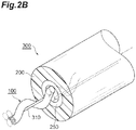
- Fig. 2B is a diagram showing an example of a structure example of the MCF cable according to the embodiment.
- the MCF cable 300 includes a support member 310, and the plurality of MCFs 100 wound on the support member 310 that serves as a center axis at predetermined pitches so as to be helically twisted around the support member 310, a reinforcing member 250 wound on the plurality of MCFs 100 so as to maintain the wound state, and a cable jacket 200 covering the periphery of the reinforcing member 250.
- the MCF cable 300 holds four MCFs 100.
- each of the plurality of MCFs 100 is wound on the support member 310 along its longitudinal direction at the predetermined pitches, so that bending with a constant radius of curvature CR is applied to each of the plurality of MCFs 100.
- the cable jacket 200 covers the whole of the reinforcing member 250 so as to protect the MCFs 100 against external force.
- the reinforcing member 250 may be, for example, an aramid fiber ("Kevlar” (registered trademark) manufactured by Du Pont-Toray Co., Ltd. or "Technora” (registered trademark) manufactured by Teijin Limited).
- the reinforcing member 250 thus provided can not only reduce elongation strain applied to the MCFs 100 when the MCF cable 300 is pulled, but also play a role of protecting the MCFs 100 against external impact by means of a cushioning effect.
- the support member 310 may be a metal material such as a tension member or an anti-shrink material that resists shrinkage of the cable jacket 200. Note that, in the example shown in Fig. 2B , only one MCF 100 is shown for the sake of simple description, but in reality, all the MCFs 100 included in the MCF cable 300 are wound on the support member 310.
- the cores may have a uniform structure or different structures.
- the number of cores in the cross section of each MCF100, and the cross-sectional diameter (glass diameter) of the MCF100 and the outer diameter of coating resin provided on the outer peripheral surface of the common cladding are appropriately set in a manner that depends on the number of cores to be included.
- the table shown in Fig. 3 lists various types of refractive index profile applicable to a region including one core and a part of cladding around the core.
- a profile shape represented by (shape of the refractive index profile of each core)/(shape of the refractive index profile of the optical cladding that covers the core) may be of any type of step/matched type (type a), recessed-tip step/matched type (type b), raised-tip step/matched type (type c), graded/matched type (type d), step/depressed type (type e), double step/matched type (type f), step/trench type (type g), or the like, and the refractive index profile of the core and the refractive index profile of the cladding can be freely combined.
- each core may have a structure based on a single mode operation in which only a single mode propagates through the core, or a structure based on a multi-mode operation in which a plurality of modes propagate.
- the coefficient of power coupling between the cores making up each coupled core group 110 corresponds to the coefficient of power coupling between LP01 of each core.
- Figs. 4A and 4B are graphs showing evaluation results of a 20 dB full width of an impulse response, mode coupling coefficient, and power coupling coefficient for a plurality of samples prepared as the coupled core group of the MCF 100 according to the embodiment.
- Fig. 4A is a graph showing a relationship between the 20 dB full width [ns] of the impulse response (pulse full time width 20 dB lower than the maximum value) and the mode coupling coefficient [m -1 ]
- Fig. 4B shows a relationship between the 20 dB full width [ns] of the impulse response and the power coupling coefficient [m -1 ].
- Each of the prepared samples 1 to 6 is an MCF including six coupled core groups 110, and each coupled core group 110 includes two cores. Further, the relative refractive index difference ⁇ of each core relative to the common cladding 120 is 0.41%, and the core diameter of each core is 9.0 ⁇ m.
- the core center-to-center distance A of the sample 1 is 12.5 ⁇ m
- the core center-to-center distance A of the sample 2 is 15.0 ⁇ m
- the core center-to-center distance A of the sample 3 is 17.5 ⁇ m
- the core center-to-center distance A of the sample 4 is 20.0 ⁇ m
- the core center-to-center distance of the sample 5 A is 25.0 ⁇ m
- the core center-to-center distance A of the sample 6 is 27.5 ⁇ m. Note that, in each of the samples 1 to 6, the six coupled core groups 110 are separated from each other by the distance D so as to sufficiently ensure the non-coupled state.
- the fiber length is set to 66 m, and the 20 dB full width of the impulse response at the wavelength of 1550 nm between cores in each coupled core group 110 is evaluated by using optical frequency domain reflectometry (OFDR). Note that, in this OFDR, light is incident from one end of each of the samples 1 to 6 wound on a bobbin with a radius of 140 mm, and the peak of Fresnel reflection at the other end is measured.
- OFDR optical frequency domain reflectometry
- the mode coupling coefficients of the prepared samples 1 to 6 fall within a range of from 1 ⁇ 10 -1 [m
- the mode coupling coefficients of the prepared samples 1 to 6 fall within a range of from 1x10 -1 [m -1 ] to 1 ⁇ 10 3 [m -1 ], but under specific conditions, it is possible to narrow down the mode coupling coefficient and the power coupling coefficient. That is, as can be seen from Figs. 4A and 4B , for the coupled core group of the sample 6, the 20 dB full width of the impulse response sharply increases.
- the mode coupling coefficient fall within a range of from 2.6 ⁇ 10 0 [m -1 ] to 1.6 ⁇ 10 2 [m -1 ] and that the power coupling coefficient fall within a range of from 1.3 ⁇ 10 -3 [m -1 ] to 8.1 ⁇ 10 [m -1 ].
- the core center-to-center distance A of each coupled core group 110 can be set so as to satisfy the above-described limited range of the mode coupling coefficient or the power coupling coefficient.
- the MCF 100 according to the embodiment be suitably bent. Further, it is desirable that torsion about the center of the common cladding (the center in the cross section of the common cladding 120 orthogonal to the longitudinal direction of the MCF 100) serving as a turning axis be applied to the MCF 100 according to the embodiment. Such torsion may be applied when glass is melted during optical fiber drawing, or may be applied in a state where the glass is solidified after the optical fiber drawing.
- the inventor has checked, by random simulation calculation, what value b has when the constant of proportionality a is set to a DGD scaling factor and, b is set to a DGD growth rate.
- the simulations are made using a mode-coupling equation for core modes.
- ⁇ ⁇ z E 1 ⁇ z E 2 ⁇ z ⁇ j ⁇ 1 ⁇ 1 + ⁇ 2 C z cos ⁇ z ⁇ ⁇ ⁇ ⁇ ⁇ 2 ⁇ 1 ⁇ ⁇ 2 C z cos ⁇ z E 1 ⁇ z E 2 ⁇ z
- ⁇ represents the coefficient of mode coupling between cores
- ⁇ represents the propagation constant of each core
- A represents the core center-to-center distance (center-to-center distance between cores)
- C represents the fiber curvature (the reciprocal of the bending radius)
- ⁇ represents the fiber turning angle with respect to the bending direction based on a certain standard.
- the transfer matrix T is transformed into the form of a group-delay operator described in Non-Patent Document 3 to obtain an eigenvalue of the group-delay operator matrix, and the DGD between spatial modes can be simulated by using a difference between the maximum value and minimum value of the eigenvalue.
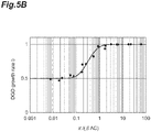
- Fig. 5B shows a result of calculation of change rates of A, C, and ⁇ for z at a plurality of levels in the wavelength band of from 1530 nm to 1625 nm.
- the coefficient of mode coupling between adjacent cores is ⁇
- the propagation constant of each of the adjacent cores is ⁇ (here, it is assumed that two cores have the same propagation constant)
- the core center-to-center distance is A. From the result shown in Fig. 5B , it is shown that the DGD growth rate b shows a clear dependence on ⁇ /( ⁇ C).
- ⁇ to be a numerator of ⁇ /( ⁇ C) denotes coupling of electric field amplitudes of two adjacent cores as known from that ⁇ is included in non-diagonal elements of the above-described Expression (5) and ( ⁇ C) to be a denominator denotes a maximum value of a difference of equivalent propagation constants affected by bending to be a diagonal element (in other words, perturbation applied by fiber bending to the core mode propagation constant).
- ⁇ /( ⁇ C) is 0.1 or less
- b takes a value near 0.5
- ⁇ /( ⁇ C) it is necessary to adjust the core structure and core arrangement to make ⁇ /( ⁇ C) 0.1 or less. That is, it is desirable that ⁇ /( ⁇ C) be 0.1 or less in order to reduce DGD between spatial modes.
- ⁇ /( ⁇ C avg ) is preferably 0.01 or more. Note that, at this time, C avg may be average curvature applied to the MCF after sufficiently control, or may be average curvature including curvature that is unintentionally applied.
- C avg preferably falls within a range of from 0.1 [m -1 ] to 20 [m -1 ], with no bending applied to the cable. Further, C avg only needs to fall within at least one of a first range of 0.3 [m -1 ] or more with no bending is applied to the cable or a second range of 10 [m -1 ] or less with no bending applied to the cable.
- ⁇ /( ⁇ C f ) is preferably 0.01 or more.
- the sample prototyped as the MCF according to the embodiment includes two to seven cores each having ring-type refractive index profile, a common optical cladding that covers the cores, and a physical cladding that covers the optical cladding and has an outer diameter of 125 ⁇ m.
- each core has an outer diameter of about 11.3 ⁇ m, and ⁇ represents a relative refractive index difference based on the refractive index of pure silica
- a difference between ⁇ of the average area of the core and ⁇ of the optical cladding is about 0.34%
- ⁇ of the physical cladding is higher than the ⁇ of the optical cladding
- a difference between the ⁇ of the physical cladding and the ⁇ of the optical cladding falls within a range of from 0.05% to 0.1%.
- D J / a ⁇ 7.68 ⁇ 10 ⁇ 2 ⁇ log 10 D offset / a 2 ⁇ 2.21 ⁇ 10 ⁇ 1 ⁇ log 10 D offset / a + 3.15 or D J / a ⁇ 7.57 ⁇ 10 ⁇ 2 ⁇ log 10 D offset / a 2 ⁇ 2.25 ⁇ 10 ⁇ 1 ⁇ log 10 D offset / a + 3.40 is satisfied, where D J represents the shortest distance between the physical cladding and the center of a core closest to the physical cladding, a represents the radius of the closest core, and D offset represents a distance between the center of the closest core and the center of the optical cladding.
- the cores and the common cladding are preferably made of glass or silica glass. Further, the common cladding may be covered with a protective member made of, for example, resin, metal, or carbon. A trace amount of alkali metal may be added to glass of each core.
- the transmission loss during all-mode excitation is preferably 0.20 dB/km or less, 0.18 dB/km or less, 0.16 dB/km or less, or 0.15 dB/km or less, in the wavelength band of from 1530 nm to 1565 nm or the wavelength band of from 1460 nm to 1625 nm.
- the mode average of chromatic dispersion is preferably 16 ps/(nm ⁇ km) or more.
- the bending loss when wound on a mandrel with a diameter of 30 mm for one turn is preferably 0.2 dB or less at the wavelength of 1550 nm.
- the bending loss when wound on a mandrel with a diameter of 20 mm is preferably 20 dB/m or less at the wavelength of 1550 nm.
- the bending loss when wound on a mandrel with a radius of 30 mm for 100 turns is preferably 0.5 dB or less at the wavelength of 1550 nm.
- the average of mode-dependent loss is preferably 0.01 dB/km 1/2 or less.
- the average of maximum DGD between spatial modes at each wavelength is preferably 10 ps/km 1/2 or less.
- the MCF cable including a plurality of MCFs each having the above-described characteristics has, in its entirety, an average of spatial mode dispersion is 10 ps/km 1/2 or less in the wavelength band of from 1530 nm to 1565 nm or the wavelength band of from 1460 nm to 1625 nm.
- the effective area of spatial mode localized in each be 60 ⁇ m 2 or more and 180 ⁇ m 2 or less in all spatial modes in order to increase the optical signal-to-noise ratio during long-haul transmission.
- the common cladding include a common optical cladding that covers all the plurality of cores making up the coupled core group and a physical cladding that covers the periphery of the optical cladding.
- the outer diameter of each of the plurality of cores be 6 ⁇ m or more and 15 ⁇ m or less.
- the difference between ⁇ of the area-weighted average of each of the plurality of cores and ⁇ of the optical cladding fall within a range of from 0.2% to 0.5%, that ⁇ of the physical cladding be greater than the ⁇ of the optical cladding, and that a difference between the ⁇ of the physical cladding and the ⁇ of the optical cladding fall within a range of from 0.0% to 1%, a range of from 0.0% to 0.5%, or a range of from 0.0% to 0.35%.
- the MCF according to the embodiment having the core structure as described above preferably has the following structure in order to increase the number of cores in the physical cladding having an outer diameter of 125 ⁇ m. That is, the coupled core group includes 2 to 7 cores, or 8 to 15 cores.
- the outer diameter of the physical cladding is 125 ⁇ 1 ⁇ m (a range of from 124 ⁇ m to 126 ⁇ m).
- D J / a ⁇ 7.68 ⁇ 10 ⁇ 2 ⁇ log 10 D offset / a 2 ⁇ 2.21 ⁇ 10 ⁇ 1 ⁇ log 10 D offset / a + 3.15 or D J / a ⁇ 7.57 ⁇ 10 ⁇ 2 ⁇ log 10 D offset / a 2 ⁇ 2.25 ⁇ 10 ⁇ 1 ⁇ log 10 D offset / a + 3.40 be satisfied, where D J represents the shortest distance between the physical cladding and the center of a core closest to the physical cladding, a represents the radius of the closest core, and D offset represents the distance between the center of the optical cladding and the center of the closest core.
- the optical fiber is represented by a series of minute uniform sections.
- power coupling between eigenmodes occurs due to a mismatch of electric field distribution between connection points of the sections caused by a change in eigenmode electric field distribution between adjacent sections.
- the power coupling is maximized at a longitudinal position (phase matching point) of the fiber where a line segment connecting the cores is orthogonal to the fiber bending radius direction.
- the power coupling coefficient between eigenmodes is maximized at the phase matching point, as has been made clear in existing document such as Non-Patent Document 6 described above.
- FIG. 6 represents a relationship between ⁇ C/(2 ⁇ ) and ⁇ /f twist , where the random coupling most frequently occurs, obtained by numerical simulation, and the solid line is a line plotted in accordance with the empirically-obtained Expression described above (Empirical fitting). As can be seen from Fig. 6 , it is possible to uniquely represent the condition under which the random mode coupling most frequently occurs independently of a difference in the average torsion f twist or the like.
- the simulation result when f twist 0.1 [turn/m] is plotted in a section between the position of arrow a1 and the position of arrow a2.
- the simulation result when f twist 1 [turn/m] is plotted in a section between the position of arrow b1 and the position of arrow b2.
- the simulation result when f twist 2 [turn/m] is plotted in a section between the position of arrow c1 and the position of arrow c2.
- the simulation result when f twist 10 [turn/m] is plotted in a section between the position of arrow d1 and the position of arrow d2.
- optical fiber transmission system 10 ... transmitting station; 11 ... transmitter (TX 1 to TX N ); 12 ... connector; 20 ... receiving station; 21 ... receiver (RX 1 to RX N ); 100 ... multicore optical fiber (MCF); 110 ... coupled core group; 120 ... common cladding; and 300 ... multicore optical fiber cable (MCF cable).
- MCF multicore optical fiber
- MCF cable multicore optical fiber cable
Landscapes
- Physics & Mathematics (AREA)
- General Physics & Mathematics (AREA)
- Optics & Photonics (AREA)
- Optical Communication System (AREA)
- Optical Fibers, Optical Fiber Cores, And Optical Fiber Bundles (AREA)
Applications Claiming Priority (2)
| Application Number | Priority Date | Filing Date | Title |
|---|---|---|---|
| JP2018074674 | 2018-04-09 | ||
| PCT/JP2019/007637 WO2019198365A1 (ja) | 2018-04-09 | 2019-02-27 | マルチコア光ファイバおよびマルチコア光ファイバケーブル |
Publications (3)
| Publication Number | Publication Date |
|---|---|
| EP3779543A1 true EP3779543A1 (de) | 2021-02-17 |
| EP3779543A4 EP3779543A4 (de) | 2021-05-12 |
| EP3779543B1 EP3779543B1 (de) | 2026-01-07 |
Family
ID=68163146
Family Applications (1)
| Application Number | Title | Priority Date | Filing Date |
|---|---|---|---|
| EP19786054.7A Active EP3779543B1 (de) | 2018-04-09 | 2019-02-27 | Mehradrige optische faser und mehradriges faseroptisches kabel |
Country Status (6)
| Country | Link |
|---|---|
| US (1) | US11256026B2 (de) |
| EP (1) | EP3779543B1 (de) |
| JP (1) | JP7268677B2 (de) |
| CN (1) | CN112219145B (de) |
| DK (1) | DK3779543T3 (de) |
| WO (1) | WO2019198365A1 (de) |
Families Citing this family (9)
| Publication number | Priority date | Publication date | Assignee | Title |
|---|---|---|---|---|
| WO2020209170A1 (ja) * | 2019-04-08 | 2020-10-15 | 日本電気株式会社 | 光増幅装置、光伝送システム、および光増幅方法 |
| JP6715372B1 (ja) * | 2019-04-25 | 2020-07-01 | 日本電信電話株式会社 | マルチコア光ファイバ及び設計方法 |
| US20230333312A1 (en) * | 2020-09-24 | 2023-10-19 | Sumitomo Electric Industries, Ltd. | Multicore optical fiber and optical transmission system |
| CN114650095B (zh) * | 2020-12-21 | 2024-05-14 | 华为技术有限公司 | 一种多芯光纤、传输系统和多芯光纤扩容方法 |
| US12242115B2 (en) * | 2020-12-25 | 2025-03-04 | Sumitomo Electric Industries, Ltd. | Cable with connector |
| US11726257B2 (en) | 2021-03-05 | 2023-08-15 | Corning Incorporated | Multicore optical fiber |
| JP7586329B2 (ja) * | 2021-08-02 | 2024-11-19 | 日本電信電話株式会社 | コア間の電力結合係数を算出する装置、方法及びシステム |
| WO2025196942A1 (ja) * | 2024-03-19 | 2025-09-25 | Ntt株式会社 | 光ファイバケーブル及びその製造方法 |
| WO2025203217A1 (ja) * | 2024-03-26 | 2025-10-02 | Ntt株式会社 | 光ファイバケーブル及びその製造方法 |
Family Cites Families (9)
| Publication number | Priority date | Publication date | Assignee | Title |
|---|---|---|---|---|
| EP3144709B1 (de) * | 2012-04-26 | 2022-10-26 | Sumitomo Electric Industries, Ltd. | Mehradrige glasfaser, mehradriges glasfaserkabel und übertragungssystem mit mehradriger glasfaser |
| JP6226905B2 (ja) * | 2015-03-30 | 2017-11-08 | 株式会社フジクラ | マルチコア光ファイバ、及び、マルチコア光ファイバの製造方法 |
| JP6453166B2 (ja) * | 2015-06-17 | 2019-01-16 | 日本電信電話株式会社 | マルチコア光ファイバ、光ファイバの製造方法、光ファイバケーブルの製造方法 |
| WO2017061184A1 (ja) * | 2015-10-08 | 2017-04-13 | 住友電気工業株式会社 | マルチコア光ファイバ、マルチコア光ファイバケーブルおよび光ファイバ伝送システム |
| CN105425335B (zh) * | 2015-12-17 | 2019-04-16 | 长飞光纤光缆股份有限公司 | 一种通信用抗弯多芯光纤 |
| US10234344B2 (en) * | 2016-02-04 | 2019-03-19 | Ofs Fitel, Llc | Compact multicore fiberoptic device for sensing components of force |
| JP6611250B2 (ja) * | 2016-03-14 | 2019-11-27 | 日本電信電話株式会社 | マルチコア光ファイバ及びマルチコア光ファイバの設計方法 |
| EP3457184A4 (de) * | 2016-05-10 | 2019-05-22 | Sumitomo Electric Industries, Ltd. | Mehradrige gekoppelte optische faser und optisches übertragungssystem damit |
| JP6798250B2 (ja) | 2016-10-26 | 2020-12-09 | 村田機械株式会社 | 走行車 |
-
2019
- 2019-02-27 CN CN201980024262.2A patent/CN112219145B/zh active Active
- 2019-02-27 EP EP19786054.7A patent/EP3779543B1/de active Active
- 2019-02-27 JP JP2020513108A patent/JP7268677B2/ja active Active
- 2019-02-27 DK DK19786054.7T patent/DK3779543T3/da active
- 2019-02-27 WO PCT/JP2019/007637 patent/WO2019198365A1/ja not_active Ceased
-
2020
- 2020-09-18 US US17/025,792 patent/US11256026B2/en active Active
Also Published As
| Publication number | Publication date |
|---|---|
| EP3779543A4 (de) | 2021-05-12 |
| DK3779543T3 (da) | 2026-02-09 |
| US11256026B2 (en) | 2022-02-22 |
| JPWO2019198365A1 (ja) | 2021-04-15 |
| JP7268677B2 (ja) | 2023-05-08 |
| WO2019198365A1 (ja) | 2019-10-17 |
| US20210003774A1 (en) | 2021-01-07 |
| CN112219145A (zh) | 2021-01-12 |
| CN112219145B (zh) | 2022-12-20 |
| EP3779543B1 (de) | 2026-01-07 |
Similar Documents
| Publication | Publication Date | Title |
|---|---|---|
| US11256026B2 (en) | Multicore optical fiber and multicore optical fiber cable | |
| JP6943302B2 (ja) | マルチコア光ファイバ、マルチコア光ファイバケーブルおよび光ファイバ伝送システム | |
| US9952382B2 (en) | Multi-core optical fiber, multi-core optical fiber cable, and optical fiber transmission system | |
| JP6372598B2 (ja) | マルチコア光ファイバ、マルチコア光ファイバケーブル、および、マルチコア光ファイバ伝送システム | |
| US10139559B2 (en) | Multi-core optical fiber, optical cable, and optical connector | |
| US9014525B2 (en) | Trench-assisted multimode optical fiber | |
| US20170285257A1 (en) | Optical fiber | |
| US6621965B2 (en) | Optical fiber cable with controlled helix-plus-EFL values and methods therefor | |
| AU2010213493B2 (en) | Duplex cables and zipcord cables and breakout cables incorporating duplex cables | |
| EP4667985A1 (de) | Mehrkernfaser | |
| Ishida et al. | Ultra-high core-density cable with multicore fiber | |
| WO2023176085A1 (ja) | マルチコア光ファイバ、光コンバイナ、およびファイバ特性測定方法 |
Legal Events
| Date | Code | Title | Description |
|---|---|---|---|
| STAA | Information on the status of an ep patent application or granted ep patent |
Free format text: STATUS: THE INTERNATIONAL PUBLICATION HAS BEEN MADE |
|
| PUAI | Public reference made under article 153(3) epc to a published international application that has entered the european phase |
Free format text: ORIGINAL CODE: 0009012 |
|
| STAA | Information on the status of an ep patent application or granted ep patent |
Free format text: STATUS: REQUEST FOR EXAMINATION WAS MADE |
|
| 17P | Request for examination filed |
Effective date: 20201013 |
|
| AK | Designated contracting states |
Kind code of ref document: A1 Designated state(s): AL AT BE BG CH CY CZ DE DK EE ES FI FR GB GR HR HU IE IS IT LI LT LU LV MC MK MT NL NO PL PT RO RS SE SI SK SM TR |
|
| AX | Request for extension of the european patent |
Extension state: BA ME |
|
| A4 | Supplementary search report drawn up and despatched |
Effective date: 20210412 |
|
| RIC1 | Information provided on ipc code assigned before grant |
Ipc: G02B 6/44 20060101AFI20210406BHEP Ipc: G02B 6/02 20060101ALI20210406BHEP |
|
| DAV | Request for validation of the european patent (deleted) | ||
| DAX | Request for extension of the european patent (deleted) | ||
| STAA | Information on the status of an ep patent application or granted ep patent |
Free format text: STATUS: EXAMINATION IS IN PROGRESS |
|
| 17Q | First examination report despatched |
Effective date: 20230324 |
|
| GRAP | Despatch of communication of intention to grant a patent |
Free format text: ORIGINAL CODE: EPIDOSNIGR1 |
|
| STAA | Information on the status of an ep patent application or granted ep patent |
Free format text: STATUS: GRANT OF PATENT IS INTENDED |
|
| INTG | Intention to grant announced |
Effective date: 20250918 |
|
| GRAS | Grant fee paid |
Free format text: ORIGINAL CODE: EPIDOSNIGR3 |
|
| GRAA | (expected) grant |
Free format text: ORIGINAL CODE: 0009210 |
|
| STAA | Information on the status of an ep patent application or granted ep patent |
Free format text: STATUS: THE PATENT HAS BEEN GRANTED |
|
| P01 | Opt-out of the competence of the unified patent court (upc) registered |
Free format text: CASE NUMBER: UPC_APP_0014237_3779543/2025 Effective date: 20251121 |
|
| AK | Designated contracting states |
Kind code of ref document: B1 Designated state(s): AL AT BE BG CH CY CZ DE DK EE ES FI FR GB GR HR HU IE IS IT LI LT LU LV MC MK MT NL NO PL PT RO RS SE SI SK SM TR |
|
| REG | Reference to a national code |
Ref country code: CH Ref legal event code: F10 Free format text: ST27 STATUS EVENT CODE: U-0-0-F10-F00 (AS PROVIDED BY THE NATIONAL OFFICE) Effective date: 20260107 Ref country code: GB Ref legal event code: FG4D |
|
| REG | Reference to a national code |
Ref country code: DE Ref legal event code: R096 Ref document number: 602019080142 Country of ref document: DE |
|
| REG | Reference to a national code |
Ref country code: IE Ref legal event code: FG4D |
|
| REG | Reference to a national code |
Ref country code: DK Ref legal event code: T3 Effective date: 20260204 |
|
| PGFP | Annual fee paid to national office [announced via postgrant information from national office to epo] |
Ref country code: GB Payment date: 20260219 Year of fee payment: 8 |
|
| PGFP | Annual fee paid to national office [announced via postgrant information from national office to epo] |
Ref country code: DE Payment date: 20260218 Year of fee payment: 8 Ref country code: DK Payment date: 20260225 Year of fee payment: 8 |
|
| PGFP | Annual fee paid to national office [announced via postgrant information from national office to epo] |
Ref country code: FR Payment date: 20260223 Year of fee payment: 8 |