EP3779378B1 - Schwingungsmesser - Google Patents
Schwingungsmesser Download PDFInfo
- Publication number
- EP3779378B1 EP3779378B1 EP18913903.3A EP18913903A EP3779378B1 EP 3779378 B1 EP3779378 B1 EP 3779378B1 EP 18913903 A EP18913903 A EP 18913903A EP 3779378 B1 EP3779378 B1 EP 3779378B1
- Authority
- EP
- European Patent Office
- Prior art keywords
- inspection target
- phase
- laser beam
- displacement
- point
- Prior art date
- Legal status (The legal status is an assumption and is not a legal conclusion. Google has not performed a legal analysis and makes no representation as to the accuracy of the status listed.)
- Active
Links
Images


Classifications
-
- G—PHYSICS
- G01—MEASURING; TESTING
- G01H—MEASUREMENT OF MECHANICAL VIBRATIONS OR ULTRASONIC, SONIC OR INFRASONIC WAVES
- G01H9/00—Measuring mechanical vibrations or ultrasonic, sonic or infrasonic waves by using radiation-sensitive means, e.g. optical means
- G01H9/002—Measuring mechanical vibrations or ultrasonic, sonic or infrasonic waves by using radiation-sensitive means, e.g. optical means for representing acoustic field distribution
-
- G—PHYSICS
- G01—MEASURING; TESTING
- G01N—INVESTIGATING OR ANALYSING MATERIALS BY DETERMINING THEIR CHEMICAL OR PHYSICAL PROPERTIES
- G01N21/00—Investigating or analysing materials by the use of optical means, i.e. using sub-millimetre waves, infrared, visible or ultraviolet light
- G01N21/84—Systems specially adapted for particular applications
- G01N21/88—Investigating the presence of flaws or contamination
- G01N21/8806—Specially adapted optical and illumination features
-
- G—PHYSICS
- G01—MEASURING; TESTING
- G01B—MEASURING LENGTH, THICKNESS OR SIMILAR LINEAR DIMENSIONS; MEASURING ANGLES; MEASURING AREAS; MEASURING IRREGULARITIES OF SURFACES OR CONTOURS
- G01B9/00—Measuring instruments characterised by the use of optical techniques
- G01B9/02—Interferometers
- G01B9/02001—Interferometers characterised by controlling or generating intrinsic radiation properties
- G01B9/02012—Interferometers characterised by controlling or generating intrinsic radiation properties using temporal intensity variation
- G01B9/02014—Interferometers characterised by controlling or generating intrinsic radiation properties using temporal intensity variation by using pulsed light
-
- G—PHYSICS
- G01—MEASURING; TESTING
- G01B—MEASURING LENGTH, THICKNESS OR SIMILAR LINEAR DIMENSIONS; MEASURING ANGLES; MEASURING AREAS; MEASURING IRREGULARITIES OF SURFACES OR CONTOURS
- G01B9/00—Measuring instruments characterised by the use of optical techniques
- G01B9/02—Interferometers
- G01B9/02055—Reduction or prevention of errors; Testing; Calibration
- G01B9/02062—Active error reduction, i.e. varying with time
- G01B9/02067—Active error reduction, i.e. varying with time by electronic control systems, i.e. using feedback acting on optics or light
-
- G—PHYSICS
- G01—MEASURING; TESTING
- G01B—MEASURING LENGTH, THICKNESS OR SIMILAR LINEAR DIMENSIONS; MEASURING ANGLES; MEASURING AREAS; MEASURING IRREGULARITIES OF SURFACES OR CONTOURS
- G01B9/00—Measuring instruments characterised by the use of optical techniques
- G01B9/02—Interferometers
- G01B9/02094—Speckle interferometers, i.e. for detecting changes in speckle pattern
- G01B9/02095—Speckle interferometers, i.e. for detecting changes in speckle pattern detecting deformation from original shape
-
- G—PHYSICS
- G01—MEASURING; TESTING
- G01B—MEASURING LENGTH, THICKNESS OR SIMILAR LINEAR DIMENSIONS; MEASURING ANGLES; MEASURING AREAS; MEASURING IRREGULARITIES OF SURFACES OR CONTOURS
- G01B9/00—Measuring instruments characterised by the use of optical techniques
- G01B9/02—Interferometers
- G01B9/02097—Self-interferometers
- G01B9/02098—Shearing interferometers
-
- G—PHYSICS
- G01—MEASURING; TESTING
- G01M—TESTING STATIC OR DYNAMIC BALANCE OF MACHINES OR STRUCTURES; TESTING OF STRUCTURES OR APPARATUS, NOT OTHERWISE PROVIDED FOR
- G01M5/00—Investigating the elasticity of structures, e.g. deflection of bridges or air-craft wings
- G01M5/0033—Investigating the elasticity of structures, e.g. deflection of bridges or air-craft wings by determining damage, crack or wear
-
- G—PHYSICS
- G01—MEASURING; TESTING
- G01M—TESTING STATIC OR DYNAMIC BALANCE OF MACHINES OR STRUCTURES; TESTING OF STRUCTURES OR APPARATUS, NOT OTHERWISE PROVIDED FOR
- G01M5/00—Investigating the elasticity of structures, e.g. deflection of bridges or air-craft wings
- G01M5/0041—Investigating the elasticity of structures, e.g. deflection of bridges or air-craft wings by determining deflection or stress
- G01M5/005—Investigating the elasticity of structures, e.g. deflection of bridges or air-craft wings by determining deflection or stress by means of external apparatus, e.g. test benches or portable test systems
-
- G—PHYSICS
- G01—MEASURING; TESTING
- G01M—TESTING STATIC OR DYNAMIC BALANCE OF MACHINES OR STRUCTURES; TESTING OF STRUCTURES OR APPARATUS, NOT OTHERWISE PROVIDED FOR
- G01M5/00—Investigating the elasticity of structures, e.g. deflection of bridges or air-craft wings
- G01M5/0066—Investigating the elasticity of structures, e.g. deflection of bridges or air-craft wings by exciting or detecting vibration or acceleration
-
- G—PHYSICS
- G01—MEASURING; TESTING
- G01M—TESTING STATIC OR DYNAMIC BALANCE OF MACHINES OR STRUCTURES; TESTING OF STRUCTURES OR APPARATUS, NOT OTHERWISE PROVIDED FOR
- G01M5/00—Investigating the elasticity of structures, e.g. deflection of bridges or air-craft wings
- G01M5/0091—Investigating the elasticity of structures, e.g. deflection of bridges or air-craft wings by using electromagnetic excitation or detection
-
- G—PHYSICS
- G01—MEASURING; TESTING
- G01N—INVESTIGATING OR ANALYSING MATERIALS BY DETERMINING THEIR CHEMICAL OR PHYSICAL PROPERTIES
- G01N29/00—Investigating or analysing materials by the use of ultrasonic, sonic or infrasonic waves; Visualisation of the interior of objects by transmitting ultrasonic or sonic waves through the object
- G01N29/22—Details, e.g. general constructional or apparatus details
- G01N29/24—Probes
- G01N29/2418—Probes using optoacoustic interaction with the material, e.g. laser radiation, photoacoustics
-
- G—PHYSICS
- G01—MEASURING; TESTING
- G01N—INVESTIGATING OR ANALYSING MATERIALS BY DETERMINING THEIR CHEMICAL OR PHYSICAL PROPERTIES
- G01N21/00—Investigating or analysing materials by the use of optical means, i.e. using sub-millimetre waves, infrared, visible or ultraviolet light
- G01N21/84—Systems specially adapted for particular applications
- G01N21/88—Investigating the presence of flaws or contamination
- G01N21/8806—Specially adapted optical and illumination features
- G01N2021/8838—Stroboscopic illumination; synchronised illumination
-
- G—PHYSICS
- G01—MEASURING; TESTING
- G01N—INVESTIGATING OR ANALYSING MATERIALS BY DETERMINING THEIR CHEMICAL OR PHYSICAL PROPERTIES
- G01N2201/00—Features of devices classified in G01N21/00
- G01N2201/06—Illumination; Optics
- G01N2201/061—Sources
- G01N2201/06113—Coherent sources; lasers
-
- G—PHYSICS
- G01—MEASURING; TESTING
- G01N—INVESTIGATING OR ANALYSING MATERIALS BY DETERMINING THEIR CHEMICAL OR PHYSICAL PROPERTIES
- G01N2201/00—Features of devices classified in G01N21/00
- G01N2201/06—Illumination; Optics
- G01N2201/063—Illuminating optical parts
- G01N2201/0635—Structured illumination, e.g. with grating
-
- G—PHYSICS
- G01—MEASURING; TESTING
- G01N—INVESTIGATING OR ANALYSING MATERIALS BY DETERMINING THEIR CHEMICAL OR PHYSICAL PROPERTIES
- G01N2291/00—Indexing codes associated with group G01N29/00
- G01N2291/02—Indexing codes associated with the analysed material
- G01N2291/023—Solids
- G01N2291/0232—Glass, ceramics, concrete or stone
-
- G—PHYSICS
- G01—MEASURING; TESTING
- G01N—INVESTIGATING OR ANALYSING MATERIALS BY DETERMINING THEIR CHEMICAL OR PHYSICAL PROPERTIES
- G01N2291/00—Indexing codes associated with group G01N29/00
- G01N2291/02—Indexing codes associated with the analysed material
- G01N2291/023—Solids
- G01N2291/0234—Metals, e.g. steel
Definitions
- the present invention relates to a vibration measurement device capable of being used for detecting defects of an object, such as, e.g., a concrete structure and a steel structure.
- a laser ultrasonic method is one of the techniques to detect defects on a surface and an inside of an object, such as, e.g., a concrete structure and a steel structure.
- vibrations of elastic waves are excited to an inspection target.
- a laser beam is irradiated to the inspection target.
- the reflected light is detected by a laser interferometer to measure the surface displacement. Since the displacement due to vibrations changes discontinuously at the location of a defect, the defect can be detected by measuring the distribution of the displacement.
- the detection laser (probe laser) of the laser interferometer is in a dot-shape, it is necessary to scan over the entire inspection region of the inspection target, causing a problem that it takes time.
- a defect detection device using speckle interferometry or speckle-sharing interferometer has been proposed.
- the laser beam from the laser beam source is branched into illumination light and reference light, and stroboscopic illumination to the inspection region is performed using the illumination light. Then, the interference pattern by the light which is the illumination light reflected at each point on the surface of the inspection target in the inspection region and the reference light is obtained.
- stroboscopic illumination to the inspection region is performed using a laser beam from a laser beam source (reference light is not branched) to obtain the interference pattern due to the light reflected from two points close to the surface of the inspection target in the inspection region.
- defect detection devices elastic waves are input from the excitation source to the inspection target. And, the image of the interference pattern is captured with a CCD camera or the like before and after the input. Then, the displacement or the distribution of the relative displacement of the inspection region in the back-and-forth direction (out-of-plane direction) is calculated from those two images. Since the displacement or the relative displacement at the location of the defect becomes discontinuous, it is possible to detect the defect present in the inspection region. In these methods, however, only one state of the elastic wave is observed. Therefore, when the wavelength of the elastic wave is smaller than the inspection region, it is easy to detect the defect if the defect happens to be in a portion where the amplitude of the wave is large. However, the detection becomes difficult when the defect is present in a portion where the amplitude is small. That is, the defect inspection capability differs depending on the location in the inspection region.
- Patent Document 1 describes a defect detection device using speckle interferometry or speckle-sharing interferometer.
- the detect detection device while exciting a continuous wave of an elastic wave from an excitation source to an inspection target, the image of the interference pattern is captured by performing stroboscopic illumination from a pulsed laser beam source at each of at least three different phases of the continuous wave, and the displacement at each point (speckle interferometry) or the relative displacement between two adjacent points (speckle-sharing interferometer) is measured.
- the full vibration state of the elastic wave can be reproduced at any position in the inspection region, and defects can be accurately detected regardless of the position in the inspection region.
- the defect detection device described in Patent Document 1 it is necessary to perform stroboscopic illumination synchronized with the phase of the excitation elastic wave.
- a method for controlling the timing of the stroboscopic illumination there are a direct modulation method for controlling the driving current of the laser and an external modulation method in which a continuous wave laser and a modulator are combined.
- the external modulation method can be applied regardless of the laser type, the direct modulation method is preferable in the viewpoint of device miniaturization.
- the direct modulation method using a semiconductor laser also has the advantage of low cost.
- an event may occur in which the interference image cannot be obtained when the surface of the inspection region has large irregularities.
- the defect detection has been described as an example.
- the same problem occurs when measuring the vibration due to the elastic wave excited to the inspection target using speckle interferometry or speckle-sharing interferometer.
- An object of the present invention solving the problems is to provide a vibration measurement device capable of obtaining an interference image more assuredly to measure vibrations even when inspecting an inspection target having large surface irregularities using a semiconductor laser.
- a vibration measurement device made to solve the above-described problems, includes:
- the optical path difference between the illumination light and the reference light needs to be shorter than the coherence length over the entire measurement region.
- the optical path difference between the light reflected from the two points close to each other on the surface of the inspection target in the measurement region needs to be shorter than the coherence length over the entire measurement region.
- the optical path difference becomes longer than the coherence length in a part of the measurement region. As a result, an interference image cannot be obtained in the entire measurement region.
- the vibration measurement device by using the wavelength stabilized laser beam source as the beam source of the illumination unit, it is possible to prevent the change of the oscillation wavelength during lighting, thereby preventing shortening of the coherence length.
- the displacement measurement unit can perform an accurate batch measurement of displacement of each point in the back-and-forth direction in the measurement region.
- a wavelength stabilized laser beam source which repeats the operation in which an oscillation laser beam generated by a semiconductor laser is introduced to a grating provided outside the semiconductor laser (where less susceptible to temperature changes), the light of a wavelength band narrower than the wavelength band of the oscillation laser beam from the semiconductor laser is selectively returned (feedbacked) to the semiconductor laser by the grating (e.g., see Patent Document 2).
- a wavelength stabilized laser beam source equipped with a mechanism for controlling the temperature of the semiconductor laser and a mechanism for detecting the wavelength of the oscillation laser beam generated by the semiconductor laser and configured to control the temperature of the semiconductor laser in accordance with the deviation of the wavelength of the oscillation laser beam from a predetermined wavelength (e.g., see Patent Document 3).
- a phase shift method of changing the phase of the light from two points to at least three different states is used. Specifically, the light from one of the two points is passed through the phase shifter to change the shift amount by the phase shifter to at least three different values. It is needless to say that the light from two points may be passed through a phase shifter to relatively change both the phases. Thus, in the entire measurement region, the relative displacement between the two adjacent points is measured in at least three mutually different phases of the elastic wave.
- the displacement measurement unit controls a phase of the elastic wave and timing of the stroboscopic illumination in the speckle-sharing interferometer to collectively measure the displacement of each point in the measurement region in the back-and-forth direction in at least three mutually different phases of the elastic wave.
- the displacement measurement unit preferably detects n th harmonic components of the elastic wave from the displacement of each point in the measuring area in the back-and-forth direction, wherein the number of phase states in the at least three phases is equal to or greater than (2n+1), and the number n is a natural number equal to or greater than 2.
- the number of phase states in the at least three phases is equal to or greater than (2n+1)
- the number n is a natural number equal to or greater than 2.
- FIG. 1 to FIG. 3 An embodiment of a vibration measurement device according to the present invention will be described with reference to FIG. 1 to FIG. 3 .
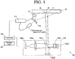
- the vibration measurement device 10 of this embodiment functions as a defect detection device for detecting a defect D (see FIG. 1 ) present on a surface of an inspection target S.
- the vibration measurement device 10 is provided with a signal generator 11, a vibrator 12, a wavelength stabilized laser beam source 13, an illumination light lens 14, a speckle-sharing interferometer 15, a controller 16, and a storage unit 17.
- the signal generator 11 is connected to the vibrator 12 by a cable.
- the signal generator 11 generates an alternating electrical signal and transmits the signal to the vibrator 12.
- the vibrator 12 is used so as to be brought into contact with the inspection target S.
- the vibrator 12 receives an alternating electrical signal from the signal generator 11, converts it into mechanical vibrations, and applies the mechanical vibrations to the inspection target S. As a result, an elastic wave is excited to the inspection target S.
- the signal generator 11 and the vibrator 12 correspond to the above-described excitation unit.
- the signal generator 11 is also connected to the wavelength stabilized laser beam source 13 by a cable separate from the cable connected to the vibrator 12.
- the signal generator 11 transmits a pulsed electrical signal (pulse signal) to the wavelength stabilized laser beam source 13 at a timing at which the alternating electrical signal becomes a predetermined phase.
- the wavelength stabilized laser beam source 13 for emitting a laser beam at a stable oscillation wavelength by performing feedback is used.
- the light of a wavelength band obtained by narrowing the oscillation laser beam generated by the semiconductor laser than the wavelength band of the oscillation laser beam is selectively returned to the semiconductor laser by a grating provided outside the semiconductor laser.
- VHG volume holographic grating
- a medium such as, e.g., a silica glass and a silicate glass
- the illumination light lens 14 is arranged between the wavelength stabilized laser beam source 13 and the inspection target S and is composed of a concave lens.
- the illumination light lens 14 has a role of expanding the pulsed laser beam from the wavelength stabilized laser beam source 13 over the entire measurement region of the surface of the inspection target S.
- the wavelength stabilized laser beam source 13 and the illumination light lens 14 are for performing stroboscopic illumination to the measurement region of the surface of the inspection target S. They correspond to the illumination unit described above.
- the speckle-sharing interferometer 15 corresponds to the above-described displacement measurement unit. It includes a beam splitter 151, a first reflecting mirror 1521, a second reflecting mirror 1522, a phase shifter 153, a condenser lens 154, and an image sensor 155.
- the beam splitter 151 is a half mirror arranged at a position where the illumination light reflected at the measurement region on the surface of the inspection target S is incident.
- the first reflecting mirror 1521 is arranged on the optical path of the illumination light reflected by the beam splitter 151, and the second reflecting mirror 1522 is arranged on the optical path of the illumination light transmitted through the beam splitter 151.
- the phase shifter 153 is arranged between the beam splitter 151 and the first reflecting mirror 1521 to change (shift) the phase of the light passing through the phase shifter 153.
- the image sensor 155 is arranged on the optical path of the illumination light reflected by the first reflecting mirror 1521 after being reflected by the beam splitter 151 and transmitted through the beam splitter 151, and the illumination light reflected by the second reflecting mirror 1522 after being transmitted through the beam splitter 151 and reflected by the beam splitter 151.
- the condenser lens 154 is arranged between the beam splitter 151 and the image sensor 155.
- the first reflecting mirror 1521 is arranged so that its reflecting surface is at an angle of 45° with respect to the reflecting surface of the beam splitter 151.
- the second reflecting mirror 1522 is arranged so that its reflecting surface is at an angle slightly inclined from 45° with respect to the reflecting surface of the beam splitter 151.
- the image sensor 155 has a number of detecting elements and detects the light incident on the image sensor 155 through the first reflecting mirror 1521 and the phase shifter 153 from a number of points on the surface of the inspection target S by respectively different detecting elements.
- the first reflecting mirror 1521 and the second reflecting mirror 1522 are arranged as described above. Therefore, in the image sensor 155, the illumination light reflected by the point A on the surface of the inspection target S and the first reflecting mirror 1521 (see the dashed line in FIG. 1 ), and the illumination light reflected by the point B slightly deviated from the point A on the surface and the second reflecting mirror 1522 (see the dashed line in FIG,.1 ) are incident on the same position of the image sensor 155 and interfere to each other.
- FIG. 1 when irregularities exist on the surface of the inspection target S, at a part of the surface, the optical path difference between the illumination light reflected at a point and the illumination light reflected at the adjacent point becomes long.
- the wavelength stabilized laser beam source 13 is used to prevent the shortening of the coherence length, which makes it possible to interfere with these two illumination light.
- the controller 16 controls the signal generator 11 and performs data processing based on the detection signal obtained from each detecting element of the image sensor 155.
- the storage unit 17 stores a detection signal obtained from each detecting element of the image sensor 155 and the data processed by the controller 16.
- the surface displacement is measured m max ⁇ 3 times in which the phase of the vibration of the vibrator 12 differs.
- the "phase of vibration of the vibrator 12" is the phase of the alternating electrical signal transmitted from the signal generator 11 to the vibrator 12, and corresponds to the phase of the elastic wave excited to the inspection target S at the point where the vibrator 12 is in contact.
- each measurement of the surface displacement is represented as "k th measurement” using the numerical value k (any natural number between 1 and m max ).
- k any natural number between 1 and m max
- Step S1 the initial value of k is set to 1 (Step S1), an alternating electrical signal is transmitted from the signal generator 11 to the vibrator 12 to initiate the application of vibration from the vibrator 12 to the inspection target S (Step S2). As a result, the elastic wave is excited in the inspection target S.
- the wavelength stabilized laser beam source 13 repeatedly emits illumination light which is a pulsed laser beam at a stable wavelength by feedback using the grating described above at each time when receiving a pulse signal.
- the diameter of the illumination light is enlarged by the illumination light lens 14, and the entire measurement region on the surface of the inspection target S is irradiated with the illumination light (Step S3).
- the illumination light is reflected on the surface of the inspection target S and incident on the beam splitter 151 of the speckle-sharing interferometer 15.
- a portion of the illumination light is reflected by the beam splitter 151 and reflected by the first reflecting mirror 1521 after passing through the phase shifter 153.
- a portion of the illumination light passes through the beam splitter 151 after passing through the phase shifter 153 again, and incident on the image sensor 155.
- the remainder of the illumination light incident on the beam splitter 151 is transmitted through the beam splitter 151 and reflected by the second reflecting mirror 1522.
- a portion thereof is reflected by the beam splitter 151 and incident on the image sensor 155.
- the illumination light reflected at a number of points on the surface of the inspection target S is detected by different detecting elements.
- the phase shifter 153 changes (shifts) the phase of the illumination light (i.e., the illumination light reflected at the point A) passing through the phase shifter 153 while the illumination light, which is a pulsed laser beam, is repeatedly output.
- the phase difference between the illumination light reflected at the point A and the illumination light reflected at the point B varies.
- each detecting element of the image sensor 155 detects the intensity of the interference light in which these two illumination light interferes (Step S4).
- the use of the wavelength stabilized laser beam source 13 prevents the shortening of the coherence length, thereby allowing the interference of the two illumination light.
- FIG. 3 an example is shown in which the shift amount of the phase by the phase shifter 153 and the intensity of the interference light detected by the detecting element of the image sensor 155, which are obtained when the phase of the vibration of the vibrator 12 is ⁇ 0 , are shown graphically.
- the relationship in which the detection intensity varies sinusoidally with respect to the phase shift amount is shown by a continuous curve.
- the above-described continuous sine waveform reproduces by a least squares method or the like from the observed data. For this purpose, it is necessary to detect the intensities in at least three different phase shift amounts.
- the process returns to Step S3.
- the signal generator 11 transmits a pulse signal to the wavelength stabilized laser beam source 13, and the wavelength stabilized laser beam source 13 repeatedly emits illumination light which is a pulsed laser beam to the surface of the inspection target S at the timing when the pulse signal is received.
- each detecting element of the image sensor 155 detects the intensity of the interference light of the illumination light reflected at the point A and passed through the phase shifter 153, etc., and the illumination light reflected at the point B (Step S4).
- the phase shift amount of the phase by the phase shifter 153 and the intensity of the interference light detected by the detecting element of the image sensor 155, which are obtained when the phase of the vibration of the vibrator 12 is ⁇ 1 are shown graphically. Contrasting the middle diagram and the upper diagram in FIG. 3 , the peak positions of the intensities of the interference light are shifted by ⁇ 1 - ⁇ 0 . This shift indicates that the phase difference between the optical path from the point A and the optical path from the point B changed due to the phase difference of the vibration of the vibrator 12 at the time of detection. The change in the phase difference of the optical path indicates that the relative displacement of the point A and the point B in the out-of-plane direction is changing.
- Step S5 since the value of k is 3 and the value has reached m max , it is determined as "YES”, and the process proceeds to Step S7.
- Step S7 the transmission of the alternating electrical signal from the signal generator 11 to the vibrator 12 is stopped. Thereby, the vibrator 12 stops the vibration.
- Steps S8 and S9 the vibration state (the amplitude and the phase) of the elastic wave at each point in the measurement region is obtained by the following operations.
- the maximum output phase shift amounts ⁇ 0 , ⁇ 1 , and ⁇ 2 in which the output of the detecting element maximizes while the phase shift amount by the phase shifter 153 is changed in the phases ⁇ 0 , ⁇ 1 , and ⁇ 2 of each vibration are obtained (see the upper, middle, and lower diagrams in FIG. 3 ).
- Step S8 the difference between these three maximum output phase shift amounts shows three sets of relative displacements of the point A and the point B in the out-of-plane direction by two data different in the phase of the vibration of the vibrator 12 (i.e. different in time).
- three parameter values i.e., the amplitude of vibration, the phase of vibration, and the center value of vibration (DC component), at each point in the measurement region are obtained (Step S9).
- Step S10 Based on the values of the amplitude and the phase at each point thus obtained, an image is generated (Step S10). For example, by configuring such that the larger the amplitude of the measurement point, the higher the brightness of the pixel corresponding to the measurement point, it is possible to express the difference in the amplitude of the vibration by the difference in the light and darkness of the image.
- a defect D on the surface of the inspection target S is detected (Step S11). For example, a defect is detected where the brightness of the pixel changes suddenly with the movement of the position on the image. Note that instead of performing the image processing, the defect may be detected by visually viewing the image by an inspector. Alternatively, the defect in the measurement region may be detected by detecting, for example, a discontinuous point without generating an image.
- Step S11 all Steps of the defect detecting method using the vibration measurement device 10 of the present embodiment are completed.
- the present invention is not limited to the above-described embodiment.
- m max 3, by selecting m max so as to be larger than the number represented by [2n+1] (n is a natural number of 2 or more), it is possible to detect up to the n th component (n th harmonic component) of the elastic wave excited on the inspection target S.
- the wavelength stabilized laser beam source 13 for stabilizing the wavelength by performing feedback by a volume holographic grating is used.
- a wavelength stabilized laser having another grating may be used.
- a laser for stabilizing the wavelength by a technique other than feedback by a grating may be used.
- Such a laser is exemplified by a wavelength stabilized laser equipped with a mechanism for controlling the temperature of the semiconductor laser and a mechanism for detecting the wavelength of the oscillation laser beam generated by the semiconductor laser and configured to control the temperature of the semiconductor laser in accordance with the deviation of the wavelength of the oscillation laser beam from a predetermined wavelength.
- the signal generator 11 and the vibrator 12 are connected by a cable (wired), and the signal generator 11 and the wavelength stabilized laser beam source 13 are connected by a cable (wired).
- these may be connected wirelessly.
- the vibrator 12 configured to be used by bringing into contact with the surface of the inspection target S is used.
- a speaker or the like placed at a position not in contact with the surface of the inspection target S may be used as the vibrator. This configuration is advantageous when an inspection target S is inspected at a position or a height at which it is difficult to bring the vibrator into contact with the surface.
- speckle-sharing interferometer 15 is used in the above-described embodiment, a speckle interferometer may be used instead.
Landscapes
- Physics & Mathematics (AREA)
- General Physics & Mathematics (AREA)
- Engineering & Computer Science (AREA)
- Aviation & Aerospace Engineering (AREA)
- Pathology (AREA)
- Health & Medical Sciences (AREA)
- Biochemistry (AREA)
- General Health & Medical Sciences (AREA)
- Chemical & Material Sciences (AREA)
- Immunology (AREA)
- Life Sciences & Earth Sciences (AREA)
- Analytical Chemistry (AREA)
- Optics & Photonics (AREA)
- Electromagnetism (AREA)
- Automation & Control Theory (AREA)
- Radar, Positioning & Navigation (AREA)
- Remote Sensing (AREA)
- Investigating Or Analyzing Materials By The Use Of Ultrasonic Waves (AREA)
- Length Measuring Devices By Optical Means (AREA)
- Investigating Materials By The Use Of Optical Means Adapted For Particular Applications (AREA)
- Measurement Of Mechanical Vibrations Or Ultrasonic Waves (AREA)
Claims (2)
- Schwingungsmesser, aufweisend:eine Anregungseinheit, welche dazu konfiguriert ist, eine elastische Welle an einem Untersuchungsziel anzuregen;eine Beleuchtungseinheit, welche dazu konfiguriert ist, stroboskopische Beleuchtung in einem Messbereich einer Oberfläche des Untersuchungsziels unter Verwendung einer wellenlängenstabilisierten Laserstrahlquelle durchzuführen, die einen Halbleiterlaser aufweist, versehen mit einem holographischen Volumengitter, wobei das holographische Volumengitter dazu konfiguriert ist, selektiv Licht, das ein schmaleres Wellenlängenband hat als ein Wellenlängenband eines Oszillationslaserstrahls von dem Halbleiterlaser zu dem Halbleiterlaser zurückzuführen; undeine Verschiebungsmessungseinheit, welche dazu konfiguriert ist, kollektiv eine Verschiebung von jedem Punkt des Messbereichs in einer vor-und-zurück-Richtung von einem Speckle-teilenden Interferometer in mindestens drei voneinander verschiedenen Phasen der elastischen Welle durch Steuern einer Phase der elastischen Welle und Timen der stroboskopischen Beleuchtung zu messen.
- Schwingungsmesser nach Anspruch 1,
wobei die Verschiebungsmessungseinheit nte harmonische Komponenten der elastischen Welle aus der Verschiebung eines jeden Punktes in der Messregion in der vor-und-zurück-Richtung erkennt, wobei die Anzahl der Phasenzustände in den mindestens drei Phasen gleich oder größer (2n+1) ist als und die Zahl n eine natürliche Zahl ist, die größer als oder gleich 2 ist.
Applications Claiming Priority (2)
| Application Number | Priority Date | Filing Date | Title |
|---|---|---|---|
| JP2018073165 | 2018-04-05 | ||
| PCT/JP2018/045902 WO2019193788A1 (ja) | 2018-04-05 | 2018-12-13 | 振動計測装置 |
Publications (3)
| Publication Number | Publication Date |
|---|---|
| EP3779378A1 EP3779378A1 (de) | 2021-02-17 |
| EP3779378A4 EP3779378A4 (de) | 2021-06-16 |
| EP3779378B1 true EP3779378B1 (de) | 2022-05-11 |
Family
ID=68100568
Family Applications (1)
| Application Number | Title | Priority Date | Filing Date |
|---|---|---|---|
| EP18913903.3A Active EP3779378B1 (de) | 2018-04-05 | 2018-12-13 | Schwingungsmesser |
Country Status (5)
| Country | Link |
|---|---|
| US (1) | US12111266B2 (de) |
| EP (1) | EP3779378B1 (de) |
| JP (1) | JP7315535B2 (de) |
| CN (1) | CN112005086A (de) |
| WO (1) | WO2019193788A1 (de) |
Families Citing this family (2)
| Publication number | Priority date | Publication date | Assignee | Title |
|---|---|---|---|---|
| KR102811974B1 (ko) * | 2021-01-21 | 2025-05-22 | 야마하 로보틱스 홀딩스 가부시키가이샤 | 불량 검출 장치 및 불량 검출 방법 |
| CN113406003B (zh) * | 2021-04-24 | 2023-05-05 | 南京理工大学 | 基于环形光束激光超声合成孔径聚焦成像装置及方法 |
Family Cites Families (26)
| Publication number | Priority date | Publication date | Assignee | Title |
|---|---|---|---|---|
| US4352565A (en) * | 1981-01-12 | 1982-10-05 | Rowe James M | Speckle pattern interferometer |
| JPH01127911A (ja) * | 1987-11-12 | 1989-05-19 | Keyence Corp | スペックルパターン干渉計 |
| US4913547A (en) * | 1988-01-29 | 1990-04-03 | Moran Steven E | Optically phased-locked speckle pattern interferometer |
| JPH01195302A (ja) * | 1988-01-29 | 1989-08-07 | Keyence Corp | スペックルパターン干渉計 |
| DE3928488A1 (de) * | 1989-08-29 | 1991-03-07 | Standard Elektrik Lorenz Ag | Interferometrisches messsystem |
| US5691989A (en) * | 1991-07-26 | 1997-11-25 | Accuwave Corporation | Wavelength stabilized laser sources using feedback from volume holograms |
| US5286313A (en) * | 1991-10-31 | 1994-02-15 | Surface Combustion, Inc. | Process control system using polarizing interferometer |
| US5604592A (en) * | 1994-09-19 | 1997-02-18 | Textron Defense Systems, Division Of Avco Corporation | Laser ultrasonics-based material analysis system and method using matched filter processing |
| US6057927A (en) * | 1998-02-25 | 2000-05-02 | American Iron And Steel Institute | Laser-ultrasound spectroscopy apparatus and method with detection of shear resonances for measuring anisotropy, thickness, and other properties |
| US6175411B1 (en) * | 1998-02-25 | 2001-01-16 | Bechtel Bwxt Idaho, Llc | Apparatus and method for measuring and imaging traveling waves |
| US20030179382A1 (en) * | 2002-02-05 | 2003-09-25 | Millipore Corporation | Use of electronic speckle interferometry for defect detection in fabricated devices |
| JP3955513B2 (ja) * | 2002-09-04 | 2007-08-08 | 株式会社日立製作所 | 欠陥検査装置及び欠陥検査方法 |
| KR100693213B1 (ko) * | 2005-08-19 | 2007-03-13 | 한국타이어 주식회사 | 레이저 스페클 전단간섭법을 이용한 타이어 접지형상측정장치 |
| CA2651341C (en) * | 2006-05-10 | 2017-01-24 | National Research Council Of Canada | Method of assessing bond integrity in bonded structures |
| JP2009081321A (ja) | 2007-09-27 | 2009-04-16 | Anritsu Corp | 波長安定化レーザ装置および方法,ならびに波長安定化レーザ装置を備えたラマン増幅器 |
| TWI371574B (en) * | 2008-08-05 | 2012-09-01 | Univ Nat Taipei Technology | Vibration resistant interferometric scanning system and method thereof |
| GB0900705D0 (en) * | 2009-01-16 | 2009-03-04 | Univ Huddersfield | Surface measurement system |
| JP5949384B2 (ja) | 2012-09-24 | 2016-07-06 | 株式会社島津製作所 | レーザ装置の製造方法 |
| CN104457581B (zh) * | 2014-08-28 | 2017-03-22 | 深圳奥比中光科技有限公司 | 一种全场z向位移测量系统 |
| US9839365B1 (en) * | 2014-11-24 | 2017-12-12 | Verily Life Sciences Llc | Applications of vasculature mapping using laser speckle imaging |
| US9931040B2 (en) * | 2015-01-14 | 2018-04-03 | Verily Life Sciences Llc | Applications of hyperspectral laser speckle imaging |
| JP6451695B2 (ja) | 2016-06-02 | 2019-01-16 | 株式会社島津製作所 | 欠陥検査方法及び欠陥検査装置 |
| IL248274B (en) * | 2016-10-09 | 2018-06-28 | Lev Aner | Optical remote sensing of vibrations |
| JP6805930B2 (ja) * | 2017-03-29 | 2020-12-23 | 株式会社島津製作所 | 振動測定装置 |
| JP6791029B2 (ja) * | 2017-06-12 | 2020-11-25 | 株式会社島津製作所 | 欠陥検出方法及び欠陥検出装置 |
| US10420469B2 (en) * | 2017-11-22 | 2019-09-24 | Hi Llc | Optical detection system for determining neural activity in brain based on water concentration |
-
2018
- 2018-12-13 US US17/044,571 patent/US12111266B2/en active Active
- 2018-12-13 JP JP2020511594A patent/JP7315535B2/ja active Active
- 2018-12-13 EP EP18913903.3A patent/EP3779378B1/de active Active
- 2018-12-13 WO PCT/JP2018/045902 patent/WO2019193788A1/ja not_active Ceased
- 2018-12-13 CN CN201880092070.0A patent/CN112005086A/zh active Pending
Also Published As
| Publication number | Publication date |
|---|---|
| EP3779378A4 (de) | 2021-06-16 |
| WO2019193788A1 (ja) | 2019-10-10 |
| EP3779378A1 (de) | 2021-02-17 |
| CN112005086A (zh) | 2020-11-27 |
| US12111266B2 (en) | 2024-10-08 |
| JPWO2019193788A1 (ja) | 2021-04-15 |
| JP7315535B2 (ja) | 2023-07-26 |
| US20210096085A1 (en) | 2021-04-01 |
Similar Documents
| Publication | Publication Date | Title |
|---|---|---|
| JP6451695B2 (ja) | 欠陥検査方法及び欠陥検査装置 | |
| US10429172B2 (en) | Defect detection method and defect detection device | |
| JP6805930B2 (ja) | 振動測定装置 | |
| US11193887B2 (en) | Defect detection method and device | |
| US10942152B2 (en) | Defect inspection device and method | |
| EP3819633A1 (de) | Defekterkennungsvorrichtung | |
| EP3779378B1 (de) | Schwingungsmesser | |
| JP7760946B2 (ja) | 欠陥検出装置及び欠陥検出方法 | |
| JP4998738B2 (ja) | 寸法測定装置及び寸法測定方法 | |
| CN116026833B (zh) | 缺陷检测装置及缺陷检测方法 | |
| JP7282882B2 (ja) | 管状体の接合部の検査方法及び装置 | |
| JP7746861B2 (ja) | 欠陥検出装置及び欠陥検出方法 | |
| JPH11160065A (ja) | 光波測距儀 |
Legal Events
| Date | Code | Title | Description |
|---|---|---|---|
| STAA | Information on the status of an ep patent application or granted ep patent |
Free format text: STATUS: THE INTERNATIONAL PUBLICATION HAS BEEN MADE |
|
| PUAI | Public reference made under article 153(3) epc to a published international application that has entered the european phase |
Free format text: ORIGINAL CODE: 0009012 |
|
| STAA | Information on the status of an ep patent application or granted ep patent |
Free format text: STATUS: REQUEST FOR EXAMINATION WAS MADE |
|
| 17P | Request for examination filed |
Effective date: 20201027 |
|
| AK | Designated contracting states |
Kind code of ref document: A1 Designated state(s): AL AT BE BG CH CY CZ DE DK EE ES FI FR GB GR HR HU IE IS IT LI LT LU LV MC MK MT NL NO PL PT RO RS SE SI SK SM TR |
|
| AX | Request for extension of the european patent |
Extension state: BA ME |
|
| A4 | Supplementary search report drawn up and despatched |
Effective date: 20210517 |
|
| RIC1 | Information provided on ipc code assigned before grant |
Ipc: G01H 9/00 20060101AFI20210510BHEP Ipc: G01B 11/00 20060101ALI20210510BHEP Ipc: G01B 11/30 20060101ALI20210510BHEP Ipc: G01J 9/02 20060101ALI20210510BHEP Ipc: G01N 21/88 20060101ALI20210510BHEP |
|
| DAV | Request for validation of the european patent (deleted) | ||
| DAX | Request for extension of the european patent (deleted) | ||
| REG | Reference to a national code |
Ref country code: DE Ref legal event code: R079 Ref document number: 602018035633 Country of ref document: DE Free format text: PREVIOUS MAIN CLASS: G01H0009000000 Ipc: G01B0009020010 |
|
| GRAP | Despatch of communication of intention to grant a patent |
Free format text: ORIGINAL CODE: EPIDOSNIGR1 |
|
| STAA | Information on the status of an ep patent application or granted ep patent |
Free format text: STATUS: GRANT OF PATENT IS INTENDED |
|
| RIC1 | Information provided on ipc code assigned before grant |
Ipc: G01N 29/24 20060101ALI20220201BHEP Ipc: G01H 9/00 20060101ALI20220201BHEP Ipc: G01B 9/02098 20220101ALI20220201BHEP Ipc: G01B 9/02055 20220101ALI20220201BHEP Ipc: G01M 5/00 20060101ALI20220201BHEP Ipc: G01B 9/02001 20220101AFI20220201BHEP |
|
| INTG | Intention to grant announced |
Effective date: 20220218 |
|
| GRAS | Grant fee paid |
Free format text: ORIGINAL CODE: EPIDOSNIGR3 |
|
| GRAA | (expected) grant |
Free format text: ORIGINAL CODE: 0009210 |
|
| STAA | Information on the status of an ep patent application or granted ep patent |
Free format text: STATUS: THE PATENT HAS BEEN GRANTED |
|
| AK | Designated contracting states |
Kind code of ref document: B1 Designated state(s): AL AT BE BG CH CY CZ DE DK EE ES FI FR GB GR HR HU IE IS IT LI LT LU LV MC MK MT NL NO PL PT RO RS SE SI SK SM TR |
|
| REG | Reference to a national code |
Ref country code: GB Ref legal event code: FG4D |
|
| REG | Reference to a national code |
Ref country code: CH Ref legal event code: EP |
|
| REG | Reference to a national code |
Ref country code: AT Ref legal event code: REF Ref document number: 1491752 Country of ref document: AT Kind code of ref document: T Effective date: 20220515 |
|
| REG | Reference to a national code |
Ref country code: DE Ref legal event code: R096 Ref document number: 602018035633 Country of ref document: DE |
|
| REG | Reference to a national code |
Ref country code: IE Ref legal event code: FG4D |
|
| REG | Reference to a national code |
Ref country code: LT Ref legal event code: MG9D |
|
| REG | Reference to a national code |
Ref country code: NL Ref legal event code: MP Effective date: 20220511 |
|
| REG | Reference to a national code |
Ref country code: AT Ref legal event code: MK05 Ref document number: 1491752 Country of ref document: AT Kind code of ref document: T Effective date: 20220511 |
|
| PG25 | Lapsed in a contracting state [announced via postgrant information from national office to epo] |
Ref country code: SE Free format text: LAPSE BECAUSE OF FAILURE TO SUBMIT A TRANSLATION OF THE DESCRIPTION OR TO PAY THE FEE WITHIN THE PRESCRIBED TIME-LIMIT Effective date: 20220511 Ref country code: PT Free format text: LAPSE BECAUSE OF FAILURE TO SUBMIT A TRANSLATION OF THE DESCRIPTION OR TO PAY THE FEE WITHIN THE PRESCRIBED TIME-LIMIT Effective date: 20220912 Ref country code: NO Free format text: LAPSE BECAUSE OF FAILURE TO SUBMIT A TRANSLATION OF THE DESCRIPTION OR TO PAY THE FEE WITHIN THE PRESCRIBED TIME-LIMIT Effective date: 20220811 Ref country code: NL Free format text: LAPSE BECAUSE OF FAILURE TO SUBMIT A TRANSLATION OF THE DESCRIPTION OR TO PAY THE FEE WITHIN THE PRESCRIBED TIME-LIMIT Effective date: 20220511 Ref country code: LT Free format text: LAPSE BECAUSE OF FAILURE TO SUBMIT A TRANSLATION OF THE DESCRIPTION OR TO PAY THE FEE WITHIN THE PRESCRIBED TIME-LIMIT Effective date: 20220511 Ref country code: HR Free format text: LAPSE BECAUSE OF FAILURE TO SUBMIT A TRANSLATION OF THE DESCRIPTION OR TO PAY THE FEE WITHIN THE PRESCRIBED TIME-LIMIT Effective date: 20220511 Ref country code: GR Free format text: LAPSE BECAUSE OF FAILURE TO SUBMIT A TRANSLATION OF THE DESCRIPTION OR TO PAY THE FEE WITHIN THE PRESCRIBED TIME-LIMIT Effective date: 20220812 Ref country code: FI Free format text: LAPSE BECAUSE OF FAILURE TO SUBMIT A TRANSLATION OF THE DESCRIPTION OR TO PAY THE FEE WITHIN THE PRESCRIBED TIME-LIMIT Effective date: 20220511 Ref country code: BG Free format text: LAPSE BECAUSE OF FAILURE TO SUBMIT A TRANSLATION OF THE DESCRIPTION OR TO PAY THE FEE WITHIN THE PRESCRIBED TIME-LIMIT Effective date: 20220811 Ref country code: AT Free format text: LAPSE BECAUSE OF FAILURE TO SUBMIT A TRANSLATION OF THE DESCRIPTION OR TO PAY THE FEE WITHIN THE PRESCRIBED TIME-LIMIT Effective date: 20220511 |
|
| PG25 | Lapsed in a contracting state [announced via postgrant information from national office to epo] |
Ref country code: RS Free format text: LAPSE BECAUSE OF FAILURE TO SUBMIT A TRANSLATION OF THE DESCRIPTION OR TO PAY THE FEE WITHIN THE PRESCRIBED TIME-LIMIT Effective date: 20220511 Ref country code: PL Free format text: LAPSE BECAUSE OF FAILURE TO SUBMIT A TRANSLATION OF THE DESCRIPTION OR TO PAY THE FEE WITHIN THE PRESCRIBED TIME-LIMIT Effective date: 20220511 Ref country code: LV Free format text: LAPSE BECAUSE OF FAILURE TO SUBMIT A TRANSLATION OF THE DESCRIPTION OR TO PAY THE FEE WITHIN THE PRESCRIBED TIME-LIMIT Effective date: 20220511 Ref country code: IS Free format text: LAPSE BECAUSE OF FAILURE TO SUBMIT A TRANSLATION OF THE DESCRIPTION OR TO PAY THE FEE WITHIN THE PRESCRIBED TIME-LIMIT Effective date: 20220911 |
|
| PG25 | Lapsed in a contracting state [announced via postgrant information from national office to epo] |
Ref country code: SM Free format text: LAPSE BECAUSE OF FAILURE TO SUBMIT A TRANSLATION OF THE DESCRIPTION OR TO PAY THE FEE WITHIN THE PRESCRIBED TIME-LIMIT Effective date: 20220511 Ref country code: SK Free format text: LAPSE BECAUSE OF FAILURE TO SUBMIT A TRANSLATION OF THE DESCRIPTION OR TO PAY THE FEE WITHIN THE PRESCRIBED TIME-LIMIT Effective date: 20220511 Ref country code: RO Free format text: LAPSE BECAUSE OF FAILURE TO SUBMIT A TRANSLATION OF THE DESCRIPTION OR TO PAY THE FEE WITHIN THE PRESCRIBED TIME-LIMIT Effective date: 20220511 Ref country code: ES Free format text: LAPSE BECAUSE OF FAILURE TO SUBMIT A TRANSLATION OF THE DESCRIPTION OR TO PAY THE FEE WITHIN THE PRESCRIBED TIME-LIMIT Effective date: 20220511 Ref country code: EE Free format text: LAPSE BECAUSE OF FAILURE TO SUBMIT A TRANSLATION OF THE DESCRIPTION OR TO PAY THE FEE WITHIN THE PRESCRIBED TIME-LIMIT Effective date: 20220511 Ref country code: DK Free format text: LAPSE BECAUSE OF FAILURE TO SUBMIT A TRANSLATION OF THE DESCRIPTION OR TO PAY THE FEE WITHIN THE PRESCRIBED TIME-LIMIT Effective date: 20220511 Ref country code: CZ Free format text: LAPSE BECAUSE OF FAILURE TO SUBMIT A TRANSLATION OF THE DESCRIPTION OR TO PAY THE FEE WITHIN THE PRESCRIBED TIME-LIMIT Effective date: 20220511 |
|
| REG | Reference to a national code |
Ref country code: DE Ref legal event code: R097 Ref document number: 602018035633 Country of ref document: DE |
|
| PLBE | No opposition filed within time limit |
Free format text: ORIGINAL CODE: 0009261 |
|
| STAA | Information on the status of an ep patent application or granted ep patent |
Free format text: STATUS: NO OPPOSITION FILED WITHIN TIME LIMIT |
|
| PG25 | Lapsed in a contracting state [announced via postgrant information from national office to epo] |
Ref country code: AL Free format text: LAPSE BECAUSE OF FAILURE TO SUBMIT A TRANSLATION OF THE DESCRIPTION OR TO PAY THE FEE WITHIN THE PRESCRIBED TIME-LIMIT Effective date: 20220511 |
|
| 26N | No opposition filed |
Effective date: 20230214 |
|
| PG25 | Lapsed in a contracting state [announced via postgrant information from national office to epo] |
Ref country code: SI Free format text: LAPSE BECAUSE OF FAILURE TO SUBMIT A TRANSLATION OF THE DESCRIPTION OR TO PAY THE FEE WITHIN THE PRESCRIBED TIME-LIMIT Effective date: 20220511 |
|
| REG | Reference to a national code |
Ref country code: CH Ref legal event code: PL |
|
| GBPC | Gb: european patent ceased through non-payment of renewal fee |
Effective date: 20221213 |
|
| REG | Reference to a national code |
Ref country code: BE Ref legal event code: MM Effective date: 20221231 |
|
| PG25 | Lapsed in a contracting state [announced via postgrant information from national office to epo] |
Ref country code: LU Free format text: LAPSE BECAUSE OF NON-PAYMENT OF DUE FEES Effective date: 20221213 |
|
| PG25 | Lapsed in a contracting state [announced via postgrant information from national office to epo] |
Ref country code: CH Free format text: LAPSE BECAUSE OF NON-PAYMENT OF DUE FEES Effective date: 20221231 Ref country code: LI Free format text: LAPSE BECAUSE OF NON-PAYMENT OF DUE FEES Effective date: 20221231 Ref country code: IE Free format text: LAPSE BECAUSE OF NON-PAYMENT OF DUE FEES Effective date: 20221213 Ref country code: GB Free format text: LAPSE BECAUSE OF NON-PAYMENT OF DUE FEES Effective date: 20221213 |
|
| PG25 | Lapsed in a contracting state [announced via postgrant information from national office to epo] |
Ref country code: FR Free format text: LAPSE BECAUSE OF NON-PAYMENT OF DUE FEES Effective date: 20221231 Ref country code: BE Free format text: LAPSE BECAUSE OF NON-PAYMENT OF DUE FEES Effective date: 20221231 |
|
| PG25 | Lapsed in a contracting state [announced via postgrant information from national office to epo] |
Ref country code: IT Free format text: LAPSE BECAUSE OF FAILURE TO SUBMIT A TRANSLATION OF THE DESCRIPTION OR TO PAY THE FEE WITHIN THE PRESCRIBED TIME-LIMIT Effective date: 20220511 |
|
| PG25 | Lapsed in a contracting state [announced via postgrant information from national office to epo] |
Ref country code: CY Free format text: LAPSE BECAUSE OF FAILURE TO SUBMIT A TRANSLATION OF THE DESCRIPTION OR TO PAY THE FEE WITHIN THE PRESCRIBED TIME-LIMIT Effective date: 20220511 |
|
| PG25 | Lapsed in a contracting state [announced via postgrant information from national office to epo] |
Ref country code: MK Free format text: LAPSE BECAUSE OF FAILURE TO SUBMIT A TRANSLATION OF THE DESCRIPTION OR TO PAY THE FEE WITHIN THE PRESCRIBED TIME-LIMIT Effective date: 20220511 Ref country code: HU Free format text: LAPSE BECAUSE OF FAILURE TO SUBMIT A TRANSLATION OF THE DESCRIPTION OR TO PAY THE FEE WITHIN THE PRESCRIBED TIME-LIMIT; INVALID AB INITIO Effective date: 20181213 |
|
| PG25 | Lapsed in a contracting state [announced via postgrant information from national office to epo] |
Ref country code: MC Free format text: LAPSE BECAUSE OF FAILURE TO SUBMIT A TRANSLATION OF THE DESCRIPTION OR TO PAY THE FEE WITHIN THE PRESCRIBED TIME-LIMIT Effective date: 20220511 |
|
| PG25 | Lapsed in a contracting state [announced via postgrant information from national office to epo] |
Ref country code: TR Free format text: LAPSE BECAUSE OF FAILURE TO SUBMIT A TRANSLATION OF THE DESCRIPTION OR TO PAY THE FEE WITHIN THE PRESCRIBED TIME-LIMIT Effective date: 20220511 Ref country code: MC Free format text: LAPSE BECAUSE OF FAILURE TO SUBMIT A TRANSLATION OF THE DESCRIPTION OR TO PAY THE FEE WITHIN THE PRESCRIBED TIME-LIMIT Effective date: 20220511 |
|
| PG25 | Lapsed in a contracting state [announced via postgrant information from national office to epo] |
Ref country code: MT Free format text: LAPSE BECAUSE OF FAILURE TO SUBMIT A TRANSLATION OF THE DESCRIPTION OR TO PAY THE FEE WITHIN THE PRESCRIBED TIME-LIMIT Effective date: 20220511 |
|
| PG25 | Lapsed in a contracting state [announced via postgrant information from national office to epo] |
Ref country code: BG Free format text: LAPSE BECAUSE OF FAILURE TO SUBMIT A TRANSLATION OF THE DESCRIPTION OR TO PAY THE FEE WITHIN THE PRESCRIBED TIME-LIMIT Effective date: 20220511 |
|
| PG25 | Lapsed in a contracting state [announced via postgrant information from national office to epo] |
Ref country code: BG Free format text: LAPSE BECAUSE OF FAILURE TO SUBMIT A TRANSLATION OF THE DESCRIPTION OR TO PAY THE FEE WITHIN THE PRESCRIBED TIME-LIMIT Effective date: 20220511 |
|
| PGFP | Annual fee paid to national office [announced via postgrant information from national office to epo] |
Ref country code: DE Payment date: 20251028 Year of fee payment: 8 |