EP3779367B1 - Vorrichtung zur messung der winkelstellung einer welle - Google Patents
Vorrichtung zur messung der winkelstellung einer welle Download PDFInfo
- Publication number
- EP3779367B1 EP3779367B1 EP20189289.0A EP20189289A EP3779367B1 EP 3779367 B1 EP3779367 B1 EP 3779367B1 EP 20189289 A EP20189289 A EP 20189289A EP 3779367 B1 EP3779367 B1 EP 3779367B1
- Authority
- EP
- European Patent Office
- Prior art keywords
- shaft
- housing part
- sensor
- housing
- projection
- Prior art date
- Legal status (The legal status is an assumption and is not a legal conclusion. Google has not performed a legal analysis and makes no representation as to the accuracy of the status listed.)
- Active
Links
Images


Classifications
-
- G—PHYSICS
- G01—MEASURING; TESTING
- G01D—MEASURING NOT SPECIALLY ADAPTED FOR A SPECIFIC VARIABLE; ARRANGEMENTS FOR MEASURING TWO OR MORE VARIABLES NOT COVERED IN A SINGLE OTHER SUBCLASS; TARIFF METERING APPARATUS; MEASURING OR TESTING NOT OTHERWISE PROVIDED FOR
- G01D5/00—Mechanical means for transferring the output of a sensing member; Means for converting the output of a sensing member to another variable where the form or nature of the sensing member does not constrain the means for converting; Transducers not specially adapted for a specific variable
- G01D5/12—Mechanical means for transferring the output of a sensing member; Means for converting the output of a sensing member to another variable where the form or nature of the sensing member does not constrain the means for converting; Transducers not specially adapted for a specific variable using electric or magnetic means
- G01D5/14—Mechanical means for transferring the output of a sensing member; Means for converting the output of a sensing member to another variable where the form or nature of the sensing member does not constrain the means for converting; Transducers not specially adapted for a specific variable using electric or magnetic means influencing the magnitude of a current or voltage
- G01D5/142—Mechanical means for transferring the output of a sensing member; Means for converting the output of a sensing member to another variable where the form or nature of the sensing member does not constrain the means for converting; Transducers not specially adapted for a specific variable using electric or magnetic means influencing the magnitude of a current or voltage using Hall-effect devices
- G01D5/145—Mechanical means for transferring the output of a sensing member; Means for converting the output of a sensing member to another variable where the form or nature of the sensing member does not constrain the means for converting; Transducers not specially adapted for a specific variable using electric or magnetic means influencing the magnitude of a current or voltage using Hall-effect devices influenced by the relative movement between the Hall device and magnetic fields
-
- G—PHYSICS
- G01—MEASURING; TESTING
- G01D—MEASURING NOT SPECIALLY ADAPTED FOR A SPECIFIC VARIABLE; ARRANGEMENTS FOR MEASURING TWO OR MORE VARIABLES NOT COVERED IN A SINGLE OTHER SUBCLASS; TARIFF METERING APPARATUS; MEASURING OR TESTING NOT OTHERWISE PROVIDED FOR
- G01D5/00—Mechanical means for transferring the output of a sensing member; Means for converting the output of a sensing member to another variable where the form or nature of the sensing member does not constrain the means for converting; Transducers not specially adapted for a specific variable
- G01D5/12—Mechanical means for transferring the output of a sensing member; Means for converting the output of a sensing member to another variable where the form or nature of the sensing member does not constrain the means for converting; Transducers not specially adapted for a specific variable using electric or magnetic means
- G01D5/244—Mechanical means for transferring the output of a sensing member; Means for converting the output of a sensing member to another variable where the form or nature of the sensing member does not constrain the means for converting; Transducers not specially adapted for a specific variable using electric or magnetic means influencing characteristics of pulses or pulse trains; generating pulses or pulse trains
- G01D5/245—Mechanical means for transferring the output of a sensing member; Means for converting the output of a sensing member to another variable where the form or nature of the sensing member does not constrain the means for converting; Transducers not specially adapted for a specific variable using electric or magnetic means influencing characteristics of pulses or pulse trains; generating pulses or pulse trains using a variable number of pulses in a train
-
- G—PHYSICS
- G01—MEASURING; TESTING
- G01B—MEASURING LENGTH, THICKNESS OR SIMILAR LINEAR DIMENSIONS; MEASURING ANGLES; MEASURING AREAS; MEASURING IRREGULARITIES OF SURFACES OR CONTOURS
- G01B7/00—Measuring arrangements characterised by the use of electric or magnetic techniques
- G01B7/003—Measuring arrangements characterised by the use of electric or magnetic techniques for measuring position, not involving coordinate determination
-
- G—PHYSICS
- G01—MEASURING; TESTING
- G01D—MEASURING NOT SPECIALLY ADAPTED FOR A SPECIFIC VARIABLE; ARRANGEMENTS FOR MEASURING TWO OR MORE VARIABLES NOT COVERED IN A SINGLE OTHER SUBCLASS; TARIFF METERING APPARATUS; MEASURING OR TESTING NOT OTHERWISE PROVIDED FOR
- G01D11/00—Component parts of measuring arrangements not specially adapted for a specific variable
- G01D11/30—Supports specially adapted for an instrument; Supports specially adapted for a set of instruments
-
- G—PHYSICS
- G01—MEASURING; TESTING
- G01D—MEASURING NOT SPECIALLY ADAPTED FOR A SPECIFIC VARIABLE; ARRANGEMENTS FOR MEASURING TWO OR MORE VARIABLES NOT COVERED IN A SINGLE OTHER SUBCLASS; TARIFF METERING APPARATUS; MEASURING OR TESTING NOT OTHERWISE PROVIDED FOR
- G01D5/00—Mechanical means for transferring the output of a sensing member; Means for converting the output of a sensing member to another variable where the form or nature of the sensing member does not constrain the means for converting; Transducers not specially adapted for a specific variable
- G01D5/12—Mechanical means for transferring the output of a sensing member; Means for converting the output of a sensing member to another variable where the form or nature of the sensing member does not constrain the means for converting; Transducers not specially adapted for a specific variable using electric or magnetic means
- G01D5/14—Mechanical means for transferring the output of a sensing member; Means for converting the output of a sensing member to another variable where the form or nature of the sensing member does not constrain the means for converting; Transducers not specially adapted for a specific variable using electric or magnetic means influencing the magnitude of a current or voltage
-
- G—PHYSICS
- G01—MEASURING; TESTING
- G01P—MEASURING LINEAR OR ANGULAR SPEED, ACCELERATION, DECELERATION, OR SHOCK; INDICATING PRESENCE, ABSENCE, OR DIRECTION, OF MOVEMENT
- G01P1/00—Details of instruments
- G01P1/02—Housings
- G01P1/026—Housings for speed measuring devices, e.g. pulse generator
-
- G—PHYSICS
- G01—MEASURING; TESTING
- G01P—MEASURING LINEAR OR ANGULAR SPEED, ACCELERATION, DECELERATION, OR SHOCK; INDICATING PRESENCE, ABSENCE, OR DIRECTION, OF MOVEMENT
- G01P3/00—Measuring linear or angular speed; Measuring differences of linear or angular speeds
- G01P3/42—Devices characterised by the use of electric or magnetic means
- G01P3/44—Devices characterised by the use of electric or magnetic means for measuring angular speed
- G01P3/48—Devices characterised by the use of electric or magnetic means for measuring angular speed by measuring frequency of generated current or voltage
- G01P3/481—Devices characterised by the use of electric or magnetic means for measuring angular speed by measuring frequency of generated current or voltage of pulse signals
- G01P3/487—Devices characterised by the use of electric or magnetic means for measuring angular speed by measuring frequency of generated current or voltage of pulse signals delivered by rotating magnets
-
- H—ELECTRICITY
- H02—GENERATION; CONVERSION OR DISTRIBUTION OF ELECTRIC POWER
- H02K—DYNAMO-ELECTRIC MACHINES
- H02K11/00—Structural association of dynamo-electric machines with electric components or with devices for shielding, monitoring or protection
- H02K11/20—Structural association of dynamo-electric machines with electric components or with devices for shielding, monitoring or protection for measuring, monitoring, testing, protecting or switching
- H02K11/21—Devices for sensing speed or position, or actuated thereby
- H02K11/215—Magnetic effect devices, e.g. Hall-effect or magneto-resistive elements
Definitions
- the present description concerns the field of angle measuring systems, which can be used, for example, to measure the angular position of shafts.
- measuring systems are required to measure the angular position of the motor shaft.
- Such measuring systems are often based on the detection of a rotating magnetic field and usually contain (among other things) one or more permanent magnets that are connected to the shaft and therefore rotate with it, as well as one or more magnetic field sensors for detecting the resulting magnetic field.
- One object underlying the invention can be seen in making existing sensor systems more efficient (e.g. with regard to costs, assembly, number of parts, reduction of installation space or similar).
- Angle measuring devices for electric motors are known, for example, from the publications DE 10 2017 104 206 A1 , DE 10 2017 212 039 and DE 102 12 859A1 A1 known.
- the device has a first housing part and a shaft arranged in the first housing part and rotatable about a rotation axis.
- the shaft has a bore that extends from one end of the shaft along the rotation axis into the shaft.
- the mentioned bore is a through hole.
- the device further comprises a magnet unit with at least one permanent magnet which is arranged within the bore and fastened to the shaft, a second housing part with a projection which extends into the bore along the axis of rotation, and a sensor unit which comprises a magnetic field sensor element arranged on a carrier, wherein the carrier is arranged inside the projection of the second housing part.
- the projection is an integral part of the second housing part.
- the projection is hollow and the magnetic field sensor element is arranged in the hollow projection.
- the second housing part forms a housing cover for the first housing part and has a central opening through which the sensor unit can be inserted.
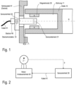
- Fig. 1 describes a sensor system coupled to a shaft for measuring the angular position and/or the rotational speed ( angular velocity ) of a shaft mounted in a housing, in particular a motor shaft of an electric motor.
- the electric motor can be, for example, a permanent magnet synchronous motor (PMSM), which is often also referred to as a brushless DC motor.
- PMSM permanent magnet synchronous motor
- the structure of such motors is basically known and therefore in Fig. 1 not shown to keep the illustration simple.
- Fig. 1 shows a shaft 10 arranged in a housing, which is mounted so as to be rotatable about a rotation axis R (for example the motor shaft of an electric motor).
- the shaft 10 has an axial bore 11, i.e. the bore 11 extends along the rotation axis R from the front side of the shaft 11 into the shaft 11.
- the bore 11 can be a blind hole or a through hole.
- the shaft 10 is a hollow shaft.
- a magnet unit 20 is arranged within the bore 11, which is attached to the shaft 10 and thus rotates with it.
- the magnet unit 20 has at least one permanent magnet.
- a housing cover 41 which lies approximately in a plane that is at right angles to the axis of rotation.
- a small gap (gap width t) between the front side of the shaft 10 and the inside of the housing cover.
- the housing cover 41 has a central opening through which a sensor unit 30 can be inserted.
- a part of the sensor unit 30 has an elongated shape (e.g. a cylindrical shape). This part lies approximately on the axis of rotation.
- the sensor unit 30 can be attached to the housing cover 41.
- the sensor unit is glued to the housing cover 41 or attached using screws.
- the sensor unit 30 can contain sensor electronics for controlling the sensor elements 31 and for (pre-)processing the sensor signals (which, however, does not necessarily have to be the case).
- the sensor unit 30 has a socket with electrical contacts 33, which enable a plug connection with a plug 402. With the help of the plug 40, a cable 41 can be connected to the sensor electronics inside the sensor unit 30.
- the sensor system comprising the sensor unit 30 and the magnet unit 20 rotating with the shaft 10 allows a measurement of the angular position of the shaft 10. The angular velocity and/or the angular acceleration of the shaft can be derived from measured angular positions.
- the block diagram in Fig. 2 schematically illustrates an electric motor M with a sensor unit 30 for measuring the angular position ⁇ of the motor shaft.
- the sensor unit 30 is connected via the cable 41 to the control unit 50, which contains the electronics for controlling the electric motor M.
- the electronics for controlling the electric motor M include, for example, a power converter (e.g. a 3-phase inverter), gate driver circuits for controlling the power transistors contained in the power converter, a microcontroller for generating the control signals for the gate driver circuits (among other things based on the information received from the sensor unit 30 about the angular position ⁇ of the motor shaft), etc.
- Fig. 3 illustrates an embodiment of a sensor unit integrated in the motor housing for measuring the angular position ⁇ of a shaft 10.
- the shaft 10 is drawn relatively large in relation to the housing.
- the Fig. 3 The elements shown are not to scale. Similar to the example from Fig. 1 the shaft 10 has an axial bore 11 along the axis of rotation R, and inside the bore 11 a magnet unit 20 is mounted, which rotates with the shaft 10 and consequently generates a magnetic field that rotates with the shaft.
- the magnet unit 20 comprises at least one permanent magnet, which generates, for example, a diametrically extending magnetic field (the direction of the field is in Fig. 3 indicated by the arrows).
- the electric motor is arranged in a first housing part 40, which can be closed laterally by means of a second housing part 41.
- the second housing part 41 is referred to below as the housing cover.
- the housing cover can have a cavity 42 and has an elongated, e.g. prism-shaped (or cylindrical) and hollow projection 43 which, when the housing cover 41 is mounted on the housing part 40, extends along the axis of rotation into the bore 11.
- the elongated projection 43 is also referred to as a tower-shaped element or a "sensor dome”.
- a carrier 34 is arranged inside the hollow projection 43, on which one or more sensor elements 31 are mounted.
- the sensor elements 31 on the carrier 34 are sensitive to magnetic fields.
- the carrier 34 can be a printed circuit board (PCB ), a lead frame, a stamped grid or the like.
- a circuit board 35 is arranged in the cavity 42 of the housing cover 41, on which the sensor electronics 32 are arranged.
- the carrier 34 is also connected to the circuit board 35 and thus enables an electrical connection of the sensor elements 31 to the sensor electronics 32.
- the carrier 34 protrudes approximately at a right angle from the circuit board 35.
- the sensor electronics 32 is designed to control the sensor elements 31 and to process the signals supplied by the sensor elements 31 in order to generate one or more measurement signals which indicate the angular position or the rotational movement of the shaft 10. Suitable sensor elements such as Hall sensors or magnetoresistive sensors as well as suitable sensor electronics are known per se and will therefore not be discussed further here.
- the sensor electronics 32 can have a socket with plug contacts in order to be able to connect a cable 41 to the sensor electronics 32 by means of a plug 40.
- the cable 41 connects (see also Fig. 2 ) the sensor electronics 32 with a control unit 50 for the electric motor.
- the elongated projection 43 (the sensor dome) may be an integral part of the housing cover 41.
- the elongated projection is fixedly connected to the main part of the housing cover 41 (in which the cavity 43 is located), e.g. by means of an adhesive or screw connection.
- the elongated projection 43 and the housing cover 41 may be made from one part (e.g. as an injection molded part from plastic).
- Fig. 4 illustrates a further embodiment which makes it possible to omit the cable 41 and the associated plug connection between the sensor electronics 32 and the control unit 50 for the electric motor M.
- the electronics used to control the electric motor cf. Fig. 2 , control unit 50
- a power converter (3-phase inverter) and the like together with the sensor electronics 32 (cf. Fig. 3 ) is integrated into the housing part 41, which simultaneously serves as the housing cover.
- the example from Fig. 5 illustrates a modification of the example from Fig. 4 , in which the housing part 41 is a conventional housing cover with a central opening. Alternatively, the housing part 41 can also be part of the housing part 40 (motor housing).
- the control unit 50 with the control electronics 51 for the electric motor and the sensor electronics is a module with a separate housing, which (like the housing cover in the previous examples) has a hollow projection 43, which is also referred to as a sensor dome.
- the projection 43 is a tower-shaped element in which the sensor element 31 is arranged on a carrier (similar to Fig. 3 ).
- control electronics 51 for the electric motor and the sensor electronics including the sensor element 31 are arranged in the same module, and a cable with a plug connector between the sensor electronics and the control electronics 51 is not required.
- the sensor element 31 is (electrically) coupled to the control electronics 51 inside the control unit 50.
- the sensor element can be arranged on a carrier (e.g. a carrier board), as is the case in the example from Fig. 3 shown.
- a hollow shaft 10' is used. It goes without saying that in all other embodiments described here, a hollow shaft can also be used instead of a solid shaft with an axial bore.
Landscapes
- Physics & Mathematics (AREA)
- General Physics & Mathematics (AREA)
- Engineering & Computer Science (AREA)
- Microelectronics & Electronic Packaging (AREA)
- Power Engineering (AREA)
Description
- Die vorliegende Beschreibung betrifft das Gebiet der Winkelmesssysteme, die beispielsweise zur Messung der Winkelposition von Wellen eingesetzt werden können.
- Beispielsweise für die Steuerung von Elektromotoren werden Messsysteme zur Messung der Winkelstellung der Motorwelle benötigt. Derartige Messsysteme basierend häufig auf der Detektion eines rotierenden Magnetfelds und beinhalten üblicherweise (unter anderem) einen oder mehrere Permanentmagneten, welche mit der Welle verbunden sind und daher mit dieser mitrotieren, sowie einen oder mehrere Magnetfeldsensoren zur Erfassung des resultierenden Magnetfeldes. Eine der Erfindung zugrunde liegende Aufgabe kann darin gesehen werden, bestehende Sensorsysteme effizienter zu gestalten (z.B. im Hinblick auf Kosten, Montage, Zahl der Teile, Reduktion des Bauraumes oder ähnliches).
- Drehwinkelmesseinrichtungen für Elektromotoren sind beispielweise aus den Publikationen
DE 10 2017 104 206 A1 ,DE 10 2017 212 039 undDE 102 12 859A1 A1 bekannt. - Die oben genannte Aufgabe wird durch eine Vorrichtung gemäß Anspruch 1 gelöst. Verschiedene Ausführungsformen und Weiterentwicklungen sind Gegenstand der abhängigen Ansprüche.
- Im Folgenden wird eine Vorrichtung zur Messung der Winkelstellung oder der Drehbewegung einer Welle beschrieben. Gemäß einem Ausführungsbeispiel weist die Vorrichtung ein erstes Gehäuseteil sowie eine in dem ersten Gehäuseteil angeordnete und um eine Rotationsachse drehbare Welle auf. Die Welle weist eine Bohrung auf, die sich von einer Stirnseite der Welle entlang der Rotationsachse in die Welle hinein erstreckt. Im Falle einer Hohlwelle ist die erwähnte Bohrung ein Durchgangsloch. Die Vorrichtung umfasst weiter eine Magneteinheit mit mindestens einem Permanentmagneten, der innerhalb der Bohrung angeordnet und an der Welle befestigt ist, ein zweites Gehäuseteil mit einem Vorsprung, der sich entlang der Rotationsachse in die Bohrung hinein erstreckt, sowie eine Sensoreinheit, die ein auf einem Träger angeordnetes Magnetfeld-Sensorelement umfasst, wobei der Träger im Inneren des Vorsprungs des zweiten Gehäuseteils angeordnet ist. Der Vorsprung ist ein integraler Bestandteil des zweiten Gehäuseteils. Der Vorsprung ist hohl und das Magnetfeld-Sensorelement ist in dem hohlen Vorsprung angeordnet. Das zweite Gehäuseteil bildet einen Gehäusedeckel für das erste Gehäuseteil und weist eine zentrale Öffnung auf, durch welche die Sensoreinheit gesteckt werden kann.
- Nachfolgend werden Ausführungsbeispiele anhand von Abbildungen näher erläutert. Die Darstellungen sind nicht zwangsläufig maßstabsgetreu und die Ausführungsbeispiele sind nicht nur auf die dargestellten Aspekte beschränkt. Vielmehr wird Wert darauf gelegt, die den Ausführungsbeispielen zugrunde liegenden Prinzipien darzustellen. Zu den Abbildungen:
-
Figur 1 illustriert ein Beispiel eines magnetischen Sensors, der am Ende einer Welle in einer zentralen axialen Bohrung der Welle angeordnet ist; der Sensor kann durch eine Öffnung im Gehäuse in die zentrale axiale Bohrung eingeschoben werden. -
Figur 2 ist ein Blockschaltbild, das exemplarisch eine Ansteuereinheit für einen Elektromotor zeigt, beispielsweise einen Stromrichter für einen bürstenlosen Gleichstrommotor. -
Figur 3 illustriert ein Ausführungsbeispiel mit in einem Gehäusedeckel integrierten magnetischen Sensor. -
Figur 4 illustriert ein Ausführungsbeispiel ähnlich wieFig. 3 , jedoch dient in diesem Fall die Ansteuereinheit für den Elektromotor als Gehäusedeckel, was eine noch kompaktere Bauweise ermöglicht. -
Figur 5 illustriert eine Modifikation des Beispiels ausFig. 4 , welche nicht durch die Ansprüche gedeckt ist. -
Fig. 1 beschreibt ein mit einer Welle gekoppeltes Sensorsystem zur Messung der Winkelstellung (angular position) und/oder der Drehgeschwindigkeit (angular velocity) einer in einem Gehäuse gelagerten Welle, insbesondere einer Motorwelle eines Elektromotors. Der Elektromotor kann beispielsweise ein Permanentmagnet-Synchronmotor (PMSM) sein, der oft auch als bürstenloser Gleichstrommotor (brushless DC motor) bezeichnet wird. Der Aufbau derartiger Motoren ist grundsätzlich bekannt und deshalb inFig. 1 nicht dargestellt, um die Darstellung einfach zu halten. -
Fig. 1 zeigt eine, in einem Gehäuse angeordnete Welle 10, die um eine Rotationsachse R drehbar gelagert ist (beispielsweise die Motorwelle eines Elektromotors). Die Welle 10 weist eine axiale Bohrung 11 auf, d.h. die Bohrung 11 erstreckt sich entlang der Rotationsachse R ausgehend von der Stirnseite der Welle 11 in die Welle 11 hinein. Die Bohrung 11 kann ein Sackloch oder ein Durchgangsloch sein. Im Falle eines Durchgangslochs ist die Welle 10 eine Hohlwelle. Innerhalb der Bohrung 11 ist eine Magneteinheit 20 angeordnet, welche an der Welle 10 befestigt ist und somit mit dieser mitrotiert. Die Magneteinheit 20 weist mindestens einen Permanentmagneten auf. InFig. 1 ist nur ein Teil des Gehäuses dargestellt, nämlich ein Gehäusedeckel 41, welcher ungefähr ein einer Ebene liegt, die rechtwinklig auf die Rotationsachse steht. Zwischen der Stirnseite der Welle 10 und der Innenseite des Gehäusedeckels kann ein kleiner Spalt liegen (Spaltbreite t). Es sind verschiedene Bauform der Magneteinheit 20 an sich bekannt. Für die hier beschriebenen Beispiele ist die konkrete Implementierung der Magneteinheit 20 an sich bekannt und wird daher hier nicht weiter diskutiert. - Der Gehäusedeckel 41 weist eine zentrale Öffnung auf, durch die eine Sensoreinheit 30 gesteckt werden kann. Ein Teil der Sensoreinheit 30 weist eine längliche Form auf (z.B. eine zylindrische Form). Dieser Teil liegt ungefähr auf der Rotationsachse Rund wird beim Durchstecken der Sensoreinheit 30 durch die Öffnung im Gehäusedeckel 41 in die Bohrung 11 eingeführt. Die Sensoreinheit 30 kann am Gehäusedeckel 41 befestigt werden. Beispielsweise wird die Sensoreinheit mit dem Gehäusedeckel 41 verklebt oder mittels Schrauben befestigt.
- Im Inneren der Sensoreinheit 30 befinden sich ein oder mehrere Sensorelemente 31, welche empfindlich auf das von der Magneteinheit 21 erzeugte Magnetfeld sind, welches mit der Welle 10 mitrotiert. Des Weiteren kann die Sensoreinheit 30 Sensorelektronik zur Ansteuerung der Sensorelemente 31 und zur (Vor-) Verarbeitung der Sensorsignale enthalten (was jedoch nicht notwendigerweise der Fall sein muss). In dem in
Fig. 1 dargestellten Beispiel weist die Sensoreinheit 30 eine Buchse mit elektrischen Kontakten 33 auf, die eine Steckverbindung mit einem Stecker 402 ermöglichen. Mit Hilfe des Steckers 40 kann ein Kabel 41 mit der Sensorelektronik im Inneren der Sensoreinheit 30 verbunden werden. Das Sensorsystem umfassend die Sensoreinheit 30 und die mit der Welle 10 mitrotierende Magneteinheit 20 erlaubt eine Messung der Winkelposition der Welle 10. Aus gemessenen Winkelpositionen kann die Winkelgeschwindigkeit und/oder die Winkelbeschleunigung der Welle abgeleitet werden. - Das Blockschaltbild in
Fig. 2 illustriert schematisch einen Elektromotor M mit einer Sensoreinheit 30 zur Messung der Winkelstellung φ der Motorwelle. Die Sensoreinheit 30 ist über das Kabel 41 mit der Ansteuereinheit 50 verbunden, die die Elektronik zur Ansteuerung des Elektromotors M enthält. Die Elektronik zur Ansteuerung des Elektromotors M beinhaltet beispielsweise einen Stromrichter (z.B. einen 3-Phasen-Inverter), Gate-Treiberschaltungen zum Ansteuern der in dem Stromrichter enthaltenen Leistungstransistoren, einen Mikrocontroller zur Erzeugung der Steuersignale für die Gate-Treiberschaltungen (u.a. basierend auf den von der Sensoreinheit 30 empfangenen Informationen über die Winkelstellung φ des Motorwelle), etc. -
Fig. 3 illustriert ein Ausführungsbeispiel einer in das Motorgehäuse integrierten Sensoreinheit zur Messung der Winkelstellung φ einer Welle 10. An dieser Stelle sei vorausgeschickt dass aus Gründen einer einfachen Darstellung inFig. 3 die Welle 10 in Relation zum Gehäuse relativ groß gezeichnet ist. Die inFig. 3 dargestellten Elemente sind nicht maßstabsgetreu. Ähnlich wie in dem Beispiel ausFig. 1 weist die Welle 10 eine axiale Bohrung 11 entlang der Rotationsache R auf, und im Inneren der Bohrung 11 ist eine Magneteinheit 20 montiert, die mit der Welle 10 mitrotiert und folglich ein mit der Welle mitrotierendes Magnetfeld erzeugt. Die Magneteinheit 20 umfasst mindestens einen Permanentmagneten, der beispielsweise ein diametral verlaufendes Magnetfeld erzeugt (die Richtung des Feldes ist inFig. 3 durch die Pfeile angedeutet). - Der Elektromotor ist in einem ersten Gehäuseteil 40 angeordnet, welches seitlich mittels eines zweiten Gehäuseteils 41 verschlossen werden kann. Das zweite Gehäuseteil 41 wird im Folgenden als Gehäusedeckel bezeichnet. Der Gehäusedeckel kann einen Hohlraum 42 aufweisen, und weist einen langgestreckten, z.B. prismenförmigen (oder zylinderförmigen) und hohlen Vorsprung 43 auf, der, wenn der Gehäusedeckel 41 am Gehäuseteil 40 montiert ist, sich entlang der Rotationsachse in die Bohrung 11 hinein erstreckt. Der langgestreckte Vorsprung 43 wird auch als turmförmiges Element oder als "Sensor-Dom" bezeichnet. Im Inneren des hohlen Vorsprungs 43 ist ein Träger 34 angeordnet, auf dem ein oder mehrere Sensorelemente 31 montiert sind. Die auf dem Träger 34 Sensorelemente 31 sind empfindlich auf Magnetfelder. Der Träger 34 kann eine Platine (printed circuit board, PCB), ein Lead-Frame, ein Stanzgitter oder ähnliches sein.
- In dem Hohlraum 42 des Gehäusedeckels 41 ist eine Platine 35 angeordnet, auf der die Sensorelektronik 32 angeordnet ist. Der Träger 34 ist ebenfalls mit der Platine 35 verbunden und ermöglicht somit eine elektrische Verbindung der Sensorelemente 31 mit der Sensorelektronik 32. Der Träger 34 steht annähernd im rechten Winkel von der Platine 35 ab. Die Sensorelektronik 32 ist dazu ausgebildet, die Sensorelemente 31 anzusteuern und die von den Sensorelementen 31 gelieferten Signale zu verarbeiten, um ein oder mehrere Messsignale zu erzeugen, welches die Winkelstellung oder die Drehbewegung der Welle 10 anzeigt. Geeignete Sensorelemente wie z.B. Hall-Sensoren oder magnetoresistive Sensoren sowie geeignete Sensorelektronik sind an sich bekannt und werden daher hier nicht weiter diskutiert. Die Sensorelektronik 32 kann eine Buchse mit Steckkontakten aufweisen, um mittels eines Steckers 40 ein Kabel 41 mit der Sensorelektronik 32 verbinden zu können. Das Kabel 41 verbindet (siehe auch
Fig. 2 ) die Sensorelektronik 32 mit einer Ansteuereinheit 50 für den Elektromotor. - Der langgestreckte Vorsprung 43 (der Sensor-Dom) kann ein integraler Bestandteil des Gehäusedeckels 41 sein. In einem Beispiel ist der langgestreckte Vorsprung mit dem Hauptteil des Gehäusedeckels 41 (in dem sich der Hohlraum 43 befindet) fest verbunden, z.B. mittels einer Klebe- oder Schraubverbindung. Das Weiteren können der langgestreckte Vorsprung 43 und der Gehäusedeckel 41 aus einem Teil gefertigt sein (beispielsweise als Spritzgussteil aus Kunststoff).
-
Fig. 4 illustriert ein weiteres Ausführungsbeispiel, welches es ermöglicht, das Kabel 41 und die zugehörigen Steckverbindung zwischen Sensorelektronik 32 und der Ansteuereinheit 50 für den Elektromotor M wegzulassen. In diesem Beispiel ist die für die Ansteuerung des Elektronmotors verwendete Elektronik (vgl.Fig. 2 , Ansteuereinheit 50) wie z.B. ein Stromrichter (3-Phasen-Inverter) und dergleichen zusammen mit der Sensorelektronik 32 (vgl.Fig. 3 ) in das Gehäuseteil 41 integriert, welches gleichzeitig als Gehäusedeckel dient. - Das Beispiel aus
Fig. 5 illustriert eine Modifikation des Beispiels ausFig. 4 , bei den das Gehäuseteil 41 ein gewöhnlicher Gehäusedeckel mit einer zentralen Öffnung ist. Alternativ kann das Gehäuseteil 41 auch Teil des Gehäuseteils 40 sein (Motorgehäuse). Die Ansteuereinheit 50 mit der Ansteuerelektronik 51 für den Elektromotor sowie die Sensorelektronik ist ein Modul mit einem separaten Gehäuse, welches (wie in den vorherigen Beispielen der Gehäusedeckel) einen hohlen Vorsprung 43 auf, der auch als Sensor-Dom bezeichnet wird. Der Vorsprung 43 ist ein turmförmiges Element, in dem das Sensorelement 31 auf einem Träger angeordnet ist (ähnlich wie inFig. 3 ). Auch in diesem Beispiel sind Ansteuerelektronik 51 für den Elektromotor und Sensorelektronik samt Sensorelement 31 in demselben Modul angeordnet, und ein Kabel mit Steckverbinder zwischen Sensorelektronik und Ansteuerelektronik 51 wird nicht benötigt. Das Sensorelement 31 ist im Inneren der Ansteuereinheit 50 mit der Ansteuerelektronik 51 (elektrisch) gekoppelt. Dabei kann das Sensorelement auf einem Träger (z.B. einer Trägerplatine) angeordnet sein, wie dies z.B. in dem Beispiel ausFig. 3 gezeigt ist. - Anders als in den vorherigen Beispielen wird gemäß
Fig. 5 statt einer Welle mit Bohrung eine Hohlwelle 10' verwendet. Es versteht sich, dass auch in allen anderen, hier beschriebenen Ausführungsbeispielen statt einer Vollwelle mit axialer Bohrung eine Hohlwelle verwendet werden kann.
Claims (5)
- Vorrichtung zur Messung einer Winkelposition einer Welle, wobei die Vorrichtung aufweist:ein Gehäuse, das ein erstes Gehäuseteil (40) und ein zweites Gehäuseteil (41) umfasst,eine in dem ersten Gehäuseteil (40) angeordnete und um eine Rotationsachse drehbare Welle (10), die eine Bohrung (11) aufweist, die sich von einer Stirnseite der Welle (10) entlang der Rotationsachse erstreckt;eine Magneteinheit (20) mit mindestens einem Permanentmagneten, der innerhalb der Bohrung (11) angeordnet und an der Welle (10) befestigt ist;wobei das zweite Gehäuseteil (41) einen Vorsprung (43) aufweist, der sich entlang der Rotationsachse in die Bohrung (11) hinein erstreckt;wobei die Vorrichtung weiter eine Sensoreinheit (30) aufweist, die ein auf einem Träger (34) angeordnetes Magnetfeld-Sensorelement (31) umfasst, wobei der Träger (34) im Inneren des Vorsprungs (43) des zweiten Gehäuseteils (41) angeordnet ist,wobei der Vorsprung (43) ein integraler Bestandteil des zweiten Gehäuseteils (41) ist, wobei der Vorsprung (43) hohl ist und das Magnetfeld-Sensorelement (31) in dem hohlen Vorsprung (43) angeordnet ist,wobei das zweite Gehäuseteil (41) einen Gehäusedeckel für das erste Gehäuseteil (40) bildet,wobei das zweite Gehäuseteil (41) eine zentrale Öffnung aufweist, durch welche die Sensoreinheit (30) gesteckt werden kann.
- Die Vorrichtung gemäß Anspruch 1,
wobei im Inneren des zweiten Gehäuseteils (41) eine Trägerplatine (35) mit Sensorelektronik angeordnet ist. - Die Vorrichtung gemäß Anspruch 1 oder 2,
wobei die Welle (10) die Motorwelle eines Elektromotors ist. - Die Vorrichtung gemäß Anspruch 3,
wobei im Inneren des zweiten Gehäuseteils (41) eine Ansteuereinheit (50) zur Ansteuerung des Elektromotors angeordnet ist. - Die Vorrichtung gemäß einem der Ansprüche 1 bis 4,
wobei die Bohrung (11) ein Durchgangsloch und folglich die Welle (10) eine Hohlwelle ist.
Applications Claiming Priority (1)
| Application Number | Priority Date | Filing Date | Title |
|---|---|---|---|
| DE102019122046.7A DE102019122046A1 (de) | 2019-08-16 | 2019-08-16 | Vorrichtung zur messung der winkelstellung einer welle |
Publications (2)
| Publication Number | Publication Date |
|---|---|
| EP3779367A1 EP3779367A1 (de) | 2021-02-17 |
| EP3779367B1 true EP3779367B1 (de) | 2024-12-18 |
Family
ID=71948442
Family Applications (1)
| Application Number | Title | Priority Date | Filing Date |
|---|---|---|---|
| EP20189289.0A Active EP3779367B1 (de) | 2019-08-16 | 2020-08-04 | Vorrichtung zur messung der winkelstellung einer welle |
Country Status (4)
| Country | Link |
|---|---|
| US (1) | US11353339B2 (de) |
| EP (1) | EP3779367B1 (de) |
| CN (1) | CN112398286B (de) |
| DE (1) | DE102019122046A1 (de) |
Families Citing this family (8)
| Publication number | Priority date | Publication date | Assignee | Title |
|---|---|---|---|---|
| EP3835792B1 (de) * | 2019-12-11 | 2024-06-12 | Treon Oy | Beschleunigungsaufnehmer und verfahren zur messung von beschleunigungsdaten |
| JP7420017B2 (ja) * | 2020-08-31 | 2024-01-23 | 株式会社プロテリアル | 回転検出装置 |
| DE202021100495U1 (de) | 2021-02-02 | 2022-05-03 | Air-Tec-Vogel GmbH | Druckluftmotor |
| CN116202633A (zh) * | 2021-12-01 | 2023-06-02 | 斯凯孚公司 | 温度传感器组件、温度感测系统及其使用方法 |
| DE102021214471A1 (de) | 2021-12-15 | 2023-06-15 | Mahle International Gmbh | Rotorwelle und Rotor |
| DE102022114476A1 (de) | 2022-02-14 | 2023-08-17 | Schaeffler Technologies AG & Co. KG | Elektrische Axialflussmaschine und elektrischer Achsantriebsstrang |
| DE102022134622A1 (de) * | 2022-12-22 | 2024-06-27 | Dr. Fritz Faulhaber GmbH & Co.KG | Motor mit Drehgeber und Trägerelement für einen Motor mit Drehgeber |
| DE102023120120B4 (de) * | 2023-07-28 | 2025-08-21 | Schaeffler Technologies AG & Co. KG | Sensoranordnung, elektrische Maschine und elektrisch betreibbarer Antriebsstrang für ein Kraftfahrzeug |
Citations (1)
| Publication number | Priority date | Publication date | Assignee | Title |
|---|---|---|---|---|
| DE10212859A1 (de) * | 2001-03-23 | 2002-10-17 | Aisin Seiki | Verschiebungssensor |
Family Cites Families (14)
| Publication number | Priority date | Publication date | Assignee | Title |
|---|---|---|---|---|
| CA2476464C (en) * | 2002-02-14 | 2011-05-03 | Bvr Technologies Company | Methods and apparatus for sensing angular position of a rotatable shaft |
| US10704933B2 (en) * | 2014-09-02 | 2020-07-07 | Infineon Technologies Ag | Integrated angle sensing device |
| DE102009034664B4 (de) * | 2009-07-24 | 2014-05-08 | Brose Fahrzeugteile Gmbh & Co. Kommanditgesellschaft, Hallstadt | Verfahren und Vorrichtung zur Ermittlung der Stellposition eines Verstellelements eines Kraftfahrzeugs |
| DE102009048389B4 (de) * | 2009-10-06 | 2019-12-19 | Asm Automation Sensorik Messtechnik Gmbh | Anordnung zur Erfassung mehr als einer Umdrehung mitels Magneten als Positionsgeber |
| DE102013011532B4 (de) * | 2013-07-10 | 2016-08-25 | Audi Ag | Drehzahlmessvorrichtung für ein Getriebe und Verfahren zur Drehzahlmessung |
| DE102014200365A1 (de) * | 2013-11-26 | 2015-05-28 | Continental Teves Ag & Co. Ohg | Sensoranordnung und Magnetisierungsvorrichtung sowie Verwendung der Sensoranordnung in einem Kraftfahrzeugsteuergerät |
| US10704926B2 (en) | 2014-09-02 | 2020-07-07 | Infineon Technologies Ag | Shaft-integrated angle sensing device |
| DE102015002562B4 (de) * | 2015-02-27 | 2019-02-14 | Brose Fahrzeugteile GmbH & Co. Kommanditgesellschaft, Würzburg | Elektrische Maschine |
| US10476341B2 (en) | 2015-02-27 | 2019-11-12 | Brose Fahrzeugteile Gmbh & Co. Kommanditgesellschaft, Wuerzburg | Motor assembly |
| JP6593625B2 (ja) * | 2015-05-25 | 2019-10-23 | 株式会社ジェイテクト | 回転角検出装置 |
| DE102017104206A1 (de) * | 2016-03-02 | 2017-09-07 | Infineon Technologies Ag | Wellenintegriertes winkelerfassungsbauelement |
| DE102016002417B4 (de) * | 2016-03-02 | 2017-12-14 | Infineon Technologies Ag | Winkelsensoranordnung und Elektrofahrrad mit einer solchen Winkelsensoranordnung |
| DE102017212039B4 (de) * | 2017-07-13 | 2021-01-21 | Hartmann-exact KG | Drehwinkelmesseinrichtung |
| DE102017216664A1 (de) * | 2017-09-20 | 2019-03-21 | Continental Teves Ag & Co. Ohg | Elektrischer Hohlwellenmotor |
-
2019
- 2019-08-16 DE DE102019122046.7A patent/DE102019122046A1/de active Pending
-
2020
- 2020-07-29 CN CN202010742545.5A patent/CN112398286B/zh active Active
- 2020-08-04 EP EP20189289.0A patent/EP3779367B1/de active Active
- 2020-08-11 US US16/990,467 patent/US11353339B2/en active Active
Patent Citations (1)
| Publication number | Priority date | Publication date | Assignee | Title |
|---|---|---|---|---|
| DE10212859A1 (de) * | 2001-03-23 | 2002-10-17 | Aisin Seiki | Verschiebungssensor |
Also Published As
| Publication number | Publication date |
|---|---|
| EP3779367A1 (de) | 2021-02-17 |
| US11353339B2 (en) | 2022-06-07 |
| CN112398286A (zh) | 2021-02-23 |
| US20210048317A1 (en) | 2021-02-18 |
| DE102019122046A1 (de) | 2021-02-18 |
| CN112398286B (zh) | 2025-06-06 |
Similar Documents
| Publication | Publication Date | Title |
|---|---|---|
| EP3779367B1 (de) | Vorrichtung zur messung der winkelstellung einer welle | |
| DE102005059538B4 (de) | Scharnier-Sensor | |
| EP0452556B1 (de) | Messwertaufnehmer für eine elektromotorisch angetriebene Servolenkung | |
| DE102007034099A1 (de) | Vorrichtung zur berührungslosen Erfassung von Relativpositionen zweier zueinander bewegbarer Teile | |
| DE102004059181A1 (de) | Maschine mit integriertem Drehgeber | |
| DE4213979A1 (de) | Vorrichtung zur messung von drehbewegungen | |
| DE102005040647A1 (de) | Elektromotorischer Hilfsantrieb für Fahrzeuge | |
| DE102012202676A1 (de) | Anordnung zum Erfassen eines Winkels mindestens einer Welle und Verfahren zum Erfassen eines Winkels mindestens einer Welle | |
| DE102010017007B4 (de) | Scharnier mit Bewegungssensor | |
| DE102020120250A1 (de) | Führungselement für einen Elektromotor | |
| EP3583681B1 (de) | Elektrische maschine | |
| DE102014223731A1 (de) | Sensorvorrichtung, Hydraulikaggregat zum Zusammenwirken mit der Sensorvorrichtung, Bremssystem und Verfahren zur Montage der Sensorvorrichtung | |
| DE102007052467A1 (de) | Displayrotationsvorrichtung | |
| DE102015007375B4 (de) | Lineare sensorvorrichtung für ein fahrzeug | |
| EP2348618A2 (de) | Aktuator | |
| EP2189763A2 (de) | Vorrichtung und Verfahren zum Anordnen eines Gehäuses in einer vorgegebenen Lage relativ zu einem Referenzobjekt | |
| DE10008540A1 (de) | Messvorrichtung zur berührungslosen Erfassung eines Drehwinkels | |
| EP1802942B1 (de) | Verfahren und vorrichtung zur berührungslosen drehwinkelerfassung | |
| EP0751279A2 (de) | Vorrichtung zur Erfassung der Bewegung eines Antriebsgurts für einen Rolladenpanzer | |
| DE10244102B4 (de) | Sensoranordnung zum Erfassen einer umdrehungsbezogenen Grösse eines elektrischen Motors | |
| DE102013000145A1 (de) | Lenksystem für ein Kraftfahrzeug sowie Kraftfahrzeug mit einem derartigen Lenksystem | |
| EP2897263B1 (de) | Elektromotor mit Drehpositionsgeber | |
| DE102011116910A1 (de) | Vorrichtung zur Erfassung von Drehwinkeln einer Welle größer als 360° | |
| EP1866606B1 (de) | Lagesensorsystem | |
| WO2013072219A2 (de) | Steuermodul für einen antriebsmotor |
Legal Events
| Date | Code | Title | Description |
|---|---|---|---|
| PUAI | Public reference made under article 153(3) epc to a published international application that has entered the european phase |
Free format text: ORIGINAL CODE: 0009012 |
|
| STAA | Information on the status of an ep patent application or granted ep patent |
Free format text: STATUS: THE APPLICATION HAS BEEN PUBLISHED |
|
| AK | Designated contracting states |
Kind code of ref document: A1 Designated state(s): AL AT BE BG CH CY CZ DE DK EE ES FI FR GB GR HR HU IE IS IT LI LT LU LV MC MK MT NL NO PL PT RO RS SE SI SK SM TR |
|
| AX | Request for extension of the european patent |
Extension state: BA ME |
|
| STAA | Information on the status of an ep patent application or granted ep patent |
Free format text: STATUS: REQUEST FOR EXAMINATION WAS MADE |
|
| 17P | Request for examination filed |
Effective date: 20210817 |
|
| RBV | Designated contracting states (corrected) |
Designated state(s): AL AT BE BG CH CY CZ DE DK EE ES FI FR GB GR HR HU IE IS IT LI LT LU LV MC MK MT NL NO PL PT RO RS SE SI SK SM TR |
|
| STAA | Information on the status of an ep patent application or granted ep patent |
Free format text: STATUS: EXAMINATION IS IN PROGRESS |
|
| 17Q | First examination report despatched |
Effective date: 20220304 |
|
| GRAP | Despatch of communication of intention to grant a patent |
Free format text: ORIGINAL CODE: EPIDOSNIGR1 |
|
| STAA | Information on the status of an ep patent application or granted ep patent |
Free format text: STATUS: GRANT OF PATENT IS INTENDED |
|
| INTG | Intention to grant announced |
Effective date: 20240802 |
|
| P01 | Opt-out of the competence of the unified patent court (upc) registered |
Free format text: CASE NUMBER: APP_51434/2024 Effective date: 20240911 |
|
| GRAS | Grant fee paid |
Free format text: ORIGINAL CODE: EPIDOSNIGR3 |
|
| GRAA | (expected) grant |
Free format text: ORIGINAL CODE: 0009210 |
|
| STAA | Information on the status of an ep patent application or granted ep patent |
Free format text: STATUS: THE PATENT HAS BEEN GRANTED |
|
| AK | Designated contracting states |
Kind code of ref document: B1 Designated state(s): AL AT BE BG CH CY CZ DE DK EE ES FI FR GB GR HR HU IE IS IT LI LT LU LV MC MK MT NL NO PL PT RO RS SE SI SK SM TR |
|
| REG | Reference to a national code |
Ref country code: CH Ref legal event code: EP |
|
| REG | Reference to a national code |
Ref country code: DE Ref legal event code: R096 Ref document number: 502020009984 Country of ref document: DE |
|
| REG | Reference to a national code |
Ref country code: IE Ref legal event code: FG4D Free format text: LANGUAGE OF EP DOCUMENT: GERMAN |
|
| REG | Reference to a national code |
Ref country code: DE Ref legal event code: R084 Ref document number: 502020009984 Country of ref document: DE |
|
| REG | Reference to a national code |
Ref country code: LT Ref legal event code: MG9D |
|
| PG25 | Lapsed in a contracting state [announced via postgrant information from national office to epo] |
Ref country code: HR Free format text: LAPSE BECAUSE OF FAILURE TO SUBMIT A TRANSLATION OF THE DESCRIPTION OR TO PAY THE FEE WITHIN THE PRESCRIBED TIME-LIMIT Effective date: 20241218 |
|
| PG25 | Lapsed in a contracting state [announced via postgrant information from national office to epo] |
Ref country code: FI Free format text: LAPSE BECAUSE OF FAILURE TO SUBMIT A TRANSLATION OF THE DESCRIPTION OR TO PAY THE FEE WITHIN THE PRESCRIBED TIME-LIMIT Effective date: 20241218 |
|
| PG25 | Lapsed in a contracting state [announced via postgrant information from national office to epo] |
Ref country code: BG Free format text: LAPSE BECAUSE OF FAILURE TO SUBMIT A TRANSLATION OF THE DESCRIPTION OR TO PAY THE FEE WITHIN THE PRESCRIBED TIME-LIMIT Effective date: 20241218 |
|
| PG25 | Lapsed in a contracting state [announced via postgrant information from national office to epo] |
Ref country code: NO Free format text: LAPSE BECAUSE OF FAILURE TO SUBMIT A TRANSLATION OF THE DESCRIPTION OR TO PAY THE FEE WITHIN THE PRESCRIBED TIME-LIMIT Effective date: 20250318 |
|
| REG | Reference to a national code |
Ref country code: NL Ref legal event code: MP Effective date: 20241218 |
|
| PG25 | Lapsed in a contracting state [announced via postgrant information from national office to epo] |
Ref country code: LV Free format text: LAPSE BECAUSE OF FAILURE TO SUBMIT A TRANSLATION OF THE DESCRIPTION OR TO PAY THE FEE WITHIN THE PRESCRIBED TIME-LIMIT Effective date: 20241218 Ref country code: GR Free format text: LAPSE BECAUSE OF FAILURE TO SUBMIT A TRANSLATION OF THE DESCRIPTION OR TO PAY THE FEE WITHIN THE PRESCRIBED TIME-LIMIT Effective date: 20250319 |
|
| PG25 | Lapsed in a contracting state [announced via postgrant information from national office to epo] |
Ref country code: RS Free format text: LAPSE BECAUSE OF FAILURE TO SUBMIT A TRANSLATION OF THE DESCRIPTION OR TO PAY THE FEE WITHIN THE PRESCRIBED TIME-LIMIT Effective date: 20250318 |
|
| PG25 | Lapsed in a contracting state [announced via postgrant information from national office to epo] |
Ref country code: NL Free format text: LAPSE BECAUSE OF FAILURE TO SUBMIT A TRANSLATION OF THE DESCRIPTION OR TO PAY THE FEE WITHIN THE PRESCRIBED TIME-LIMIT Effective date: 20241218 |
|
| PG25 | Lapsed in a contracting state [announced via postgrant information from national office to epo] |
Ref country code: SM Free format text: LAPSE BECAUSE OF FAILURE TO SUBMIT A TRANSLATION OF THE DESCRIPTION OR TO PAY THE FEE WITHIN THE PRESCRIBED TIME-LIMIT Effective date: 20241218 |
|
| PG25 | Lapsed in a contracting state [announced via postgrant information from national office to epo] |
Ref country code: PL Free format text: LAPSE BECAUSE OF FAILURE TO SUBMIT A TRANSLATION OF THE DESCRIPTION OR TO PAY THE FEE WITHIN THE PRESCRIBED TIME-LIMIT Effective date: 20241218 |
|
| PG25 | Lapsed in a contracting state [announced via postgrant information from national office to epo] |
Ref country code: ES Free format text: LAPSE BECAUSE OF FAILURE TO SUBMIT A TRANSLATION OF THE DESCRIPTION OR TO PAY THE FEE WITHIN THE PRESCRIBED TIME-LIMIT Effective date: 20241218 |
|
| PG25 | Lapsed in a contracting state [announced via postgrant information from national office to epo] |
Ref country code: IS Free format text: LAPSE BECAUSE OF FAILURE TO SUBMIT A TRANSLATION OF THE DESCRIPTION OR TO PAY THE FEE WITHIN THE PRESCRIBED TIME-LIMIT Effective date: 20250418 |
|
| PG25 | Lapsed in a contracting state [announced via postgrant information from national office to epo] |
Ref country code: PT Free format text: LAPSE BECAUSE OF FAILURE TO SUBMIT A TRANSLATION OF THE DESCRIPTION OR TO PAY THE FEE WITHIN THE PRESCRIBED TIME-LIMIT Effective date: 20250421 |
|
| PG25 | Lapsed in a contracting state [announced via postgrant information from national office to epo] |
Ref country code: EE Free format text: LAPSE BECAUSE OF FAILURE TO SUBMIT A TRANSLATION OF THE DESCRIPTION OR TO PAY THE FEE WITHIN THE PRESCRIBED TIME-LIMIT Effective date: 20241218 |
|
| PG25 | Lapsed in a contracting state [announced via postgrant information from national office to epo] |
Ref country code: RO Free format text: LAPSE BECAUSE OF FAILURE TO SUBMIT A TRANSLATION OF THE DESCRIPTION OR TO PAY THE FEE WITHIN THE PRESCRIBED TIME-LIMIT Effective date: 20241218 |
|
| PG25 | Lapsed in a contracting state [announced via postgrant information from national office to epo] |
Ref country code: SK Free format text: LAPSE BECAUSE OF FAILURE TO SUBMIT A TRANSLATION OF THE DESCRIPTION OR TO PAY THE FEE WITHIN THE PRESCRIBED TIME-LIMIT Effective date: 20241218 |
|
| PG25 | Lapsed in a contracting state [announced via postgrant information from national office to epo] |
Ref country code: CZ Free format text: LAPSE BECAUSE OF FAILURE TO SUBMIT A TRANSLATION OF THE DESCRIPTION OR TO PAY THE FEE WITHIN THE PRESCRIBED TIME-LIMIT Effective date: 20241218 |
|
| PG25 | Lapsed in a contracting state [announced via postgrant information from national office to epo] |
Ref country code: IT Free format text: LAPSE BECAUSE OF FAILURE TO SUBMIT A TRANSLATION OF THE DESCRIPTION OR TO PAY THE FEE WITHIN THE PRESCRIBED TIME-LIMIT Effective date: 20241218 |
|
| PG25 | Lapsed in a contracting state [announced via postgrant information from national office to epo] |
Ref country code: SE Free format text: LAPSE BECAUSE OF FAILURE TO SUBMIT A TRANSLATION OF THE DESCRIPTION OR TO PAY THE FEE WITHIN THE PRESCRIBED TIME-LIMIT Effective date: 20241218 |
|
| REG | Reference to a national code |
Ref country code: DE Ref legal event code: R097 Ref document number: 502020009984 Country of ref document: DE |
|
| PG25 | Lapsed in a contracting state [announced via postgrant information from national office to epo] |
Ref country code: DK Free format text: LAPSE BECAUSE OF FAILURE TO SUBMIT A TRANSLATION OF THE DESCRIPTION OR TO PAY THE FEE WITHIN THE PRESCRIBED TIME-LIMIT Effective date: 20241218 |
|
| PGFP | Annual fee paid to national office [announced via postgrant information from national office to epo] |
Ref country code: FR Payment date: 20250828 Year of fee payment: 6 |
|
| PLBE | No opposition filed within time limit |
Free format text: ORIGINAL CODE: 0009261 |
|
| STAA | Information on the status of an ep patent application or granted ep patent |
Free format text: STATUS: NO OPPOSITION FILED WITHIN TIME LIMIT |
|
| 26N | No opposition filed |
Effective date: 20250919 |
|
| PGFP | Annual fee paid to national office [announced via postgrant information from national office to epo] |
Ref country code: DE Payment date: 20251021 Year of fee payment: 6 |