EP3779293A1 - Klimaanlage - Google Patents
Klimaanlage Download PDFInfo
- Publication number
- EP3779293A1 EP3779293A1 EP18929878.9A EP18929878A EP3779293A1 EP 3779293 A1 EP3779293 A1 EP 3779293A1 EP 18929878 A EP18929878 A EP 18929878A EP 3779293 A1 EP3779293 A1 EP 3779293A1
- Authority
- EP
- European Patent Office
- Prior art keywords
- air intake
- air
- air conditioner
- intake plate
- filter screen
- Prior art date
- Legal status (The legal status is an assumption and is not a legal conclusion. Google has not performed a legal analysis and makes no representation as to the accuracy of the status listed.)
- Granted
Links
Images




Classifications
-
- F—MECHANICAL ENGINEERING; LIGHTING; HEATING; WEAPONS; BLASTING
- F24—HEATING; RANGES; VENTILATING
- F24F—AIR-CONDITIONING; AIR-HUMIDIFICATION; VENTILATION; USE OF AIR CURRENTS FOR SCREENING
- F24F1/00—Room units for air-conditioning, e.g. separate or self-contained units or units receiving primary air from a central station
- F24F1/0007—Indoor units, e.g. fan coil units
- F24F1/0071—Indoor units, e.g. fan coil units with means for purifying supplied air
- F24F1/0073—Indoor units, e.g. fan coil units with means for purifying supplied air characterised by the mounting or arrangement of filters
-
- F—MECHANICAL ENGINEERING; LIGHTING; HEATING; WEAPONS; BLASTING
- F24—HEATING; RANGES; VENTILATING
- F24F—AIR-CONDITIONING; AIR-HUMIDIFICATION; VENTILATION; USE OF AIR CURRENTS FOR SCREENING
- F24F1/00—Room units for air-conditioning, e.g. separate or self-contained units or units receiving primary air from a central station
- F24F1/0007—Indoor units, e.g. fan coil units
-
- F—MECHANICAL ENGINEERING; LIGHTING; HEATING; WEAPONS; BLASTING
- F24—HEATING; RANGES; VENTILATING
- F24F—AIR-CONDITIONING; AIR-HUMIDIFICATION; VENTILATION; USE OF AIR CURRENTS FOR SCREENING
- F24F13/00—Details common to, or for air-conditioning, air-humidification, ventilation or use of air currents for screening
- F24F13/08—Air-flow control members, e.g. louvres, grilles, flaps or guide plates
- F24F13/082—Grilles, registers or guards
- F24F13/085—Grilles, registers or guards including an air filter
-
- F—MECHANICAL ENGINEERING; LIGHTING; HEATING; WEAPONS; BLASTING
- F24—HEATING; RANGES; VENTILATING
- F24F—AIR-CONDITIONING; AIR-HUMIDIFICATION; VENTILATION; USE OF AIR CURRENTS FOR SCREENING
- F24F13/00—Details common to, or for air-conditioning, air-humidification, ventilation or use of air currents for screening
- F24F13/08—Air-flow control members, e.g. louvres, grilles, flaps or guide plates
- F24F13/10—Air-flow control members, e.g. louvres, grilles, flaps or guide plates movable, e.g. dampers
- F24F13/14—Air-flow control members, e.g. louvres, grilles, flaps or guide plates movable, e.g. dampers built up of tilting members, e.g. louvre
-
- F—MECHANICAL ENGINEERING; LIGHTING; HEATING; WEAPONS; BLASTING
- F24—HEATING; RANGES; VENTILATING
- F24F—AIR-CONDITIONING; AIR-HUMIDIFICATION; VENTILATION; USE OF AIR CURRENTS FOR SCREENING
- F24F13/00—Details common to, or for air-conditioning, air-humidification, ventilation or use of air currents for screening
- F24F13/08—Air-flow control members, e.g. louvres, grilles, flaps or guide plates
- F24F13/10—Air-flow control members, e.g. louvres, grilles, flaps or guide plates movable, e.g. dampers
- F24F13/14—Air-flow control members, e.g. louvres, grilles, flaps or guide plates movable, e.g. dampers built up of tilting members, e.g. louvre
- F24F13/1426—Air-flow control members, e.g. louvres, grilles, flaps or guide plates movable, e.g. dampers built up of tilting members, e.g. louvre characterised by actuating means
-
- F—MECHANICAL ENGINEERING; LIGHTING; HEATING; WEAPONS; BLASTING
- F24—HEATING; RANGES; VENTILATING
- F24F—AIR-CONDITIONING; AIR-HUMIDIFICATION; VENTILATION; USE OF AIR CURRENTS FOR SCREENING
- F24F13/00—Details common to, or for air-conditioning, air-humidification, ventilation or use of air currents for screening
- F24F13/28—Arrangement or mounting of filters
-
- F—MECHANICAL ENGINEERING; LIGHTING; HEATING; WEAPONS; BLASTING
- F24—HEATING; RANGES; VENTILATING
- F24F—AIR-CONDITIONING; AIR-HUMIDIFICATION; VENTILATION; USE OF AIR CURRENTS FOR SCREENING
- F24F13/00—Details common to, or for air-conditioning, air-humidification, ventilation or use of air currents for screening
- F24F13/08—Air-flow control members, e.g. louvres, grilles, flaps or guide plates
- F24F13/10—Air-flow control members, e.g. louvres, grilles, flaps or guide plates movable, e.g. dampers
- F24F13/14—Air-flow control members, e.g. louvres, grilles, flaps or guide plates movable, e.g. dampers built up of tilting members, e.g. louvre
- F24F13/1426—Air-flow control members, e.g. louvres, grilles, flaps or guide plates movable, e.g. dampers built up of tilting members, e.g. louvre characterised by actuating means
- F24F2013/1446—Air-flow control members, e.g. louvres, grilles, flaps or guide plates movable, e.g. dampers built up of tilting members, e.g. louvre characterised by actuating means with gearings
Definitions
- the present invention relates to the field of air conditioning technology, and more particularly relates to an air conditioner.
- the size of the air conditioner may affect the performance of the air conditioner.
- a size of an air inlet of the air conditioner cannot be too small in order to ensure the amount of intake air.
- a filter screen needs to be additionally provided to prevent abnormalities, such as dust, from entering the air inlet.
- the addition of the filter screen greatly affects the amount of the intake air, so that the size of the air inlet has to be increased, which may unfavorably affect the appearance of the air conditioner as well.
- the area of the air inlet can be increased when the requirement for the intake air amount is relatively large, and area of the air inlet can be reduced when the air conditioner is not being used, or when the requirement for the intake air amount is relatively small, without affecting the appearance of the air conditioner.
- An object of the present invention is to provide an air conditioner to solve the problem that the air intake area of the existing air conditioner cannot be adjusted.
- An air conditioner includes an air conditioner body, air intake plates, and a filter screen.
- the air conditioner body is provided with an air inlet and an air outlet.
- the air intake plates cover the air inlet and each has an air intake grid.
- the air intake plates are hingedly connected to the air conditioner body and are capable of being switched between an expanded state and a closed state.
- the filter screen is disposed between the air intake plates and the air inlet, and the filter screen is configured to filter air entering the air conditioner body from the air intake grid.
- the air intake plates are designed to be a structure capable of expanding and closing.
- air is taken in through the entire air inlet instead of from the air intake grid, thereby increasing the air intake area.
- the air intake plates are in the closed state, the air intake area is reduced, but the amount of the intake air reaches a certain extent, without affecting the appearance of the air conditioner.
- the air conditioner according to the above-mentioned embodiment of the present invention can include additional technical features as follows.
- the number of the air intake plates are two.
- the two air intake plates are respectively mounted on two sides of the air conditioner body.
- the two air intake plates are respectively a first air intake plate and a second air intake plate.
- One side of the first air intake plate is hingedly connected to the air conditioner body via a first rotating mechanism.
- another side of the first air intake plate is detachably connected to the air conditioner body via a connecting mechanism.
- the connecting mechanism is a snap-fit structure.
- the first rotating mechanism includes a gear and a toothed fixing member meshed with each other.
- the toothed fixing member has a plurality of teeth evenly spaced and distributed along a circular arc.
- the gear is mounted on the air conditioner body.
- the toothed fixing member is disposed on an inner side of the first air intake plate.
- two toothed fixing members are respectively disposed at an upper end and a lower end of the inner side of the first air intake plate.
- the air conditioner body is provided with two gears mating with the two toothed fixing members.
- a central angle corresponding to the circular arc is 90 degrees.
- one side of the second air intake plate is hingedly connected to the air conditioner body via a second rotating mechanism.
- the second rotating mechanism is a hinge.
- another side of the second air intake plate is connected to the air conditioner body via a push-pull mechanism configured to make the other side of the second air intake plate distant from and adjacent to the air conditioner body.
- the push-pull mechanism includes a linear reciprocal moving mechanism
- the linear reciprocal moving mechanism includes a fixing portion and a linear moving portion connected with each other.
- the fixing portion is mounted on the air conditioner body.
- the linear moving portion is connected to the second air intake plate.
- the push-pull mechanism includes a gear and a rack.
- the gear is mounted on the air conditioner body.
- the rack is respectively connected to the gear and the second air intake plate.
- the first air intake plate and the second air intake plate are respectively located at the two sides of the air conditioner body, and the two sides are adjacent to each other.
- the first air intake plate and the second air intake plate rotate in opposite directions during expanding.
- the filter screen is a flexible filter screen.
- the filter screen includes a first filter screen body, a second filter screen body, and a third filter screen body.
- the first filter screen body is connected to the air conditioner body and the first air intake plate.
- the second filter screen body is connected to the first air intake plate and the second air intake plate.
- the third filter screen body is connected to the air conditioner body and the second air intake plate.
- the first filter screen body includes a first portion and a second portion. Two opposite sides of the first portion are respectively connected to the air conditioner body and an upper end of the first air intake plate. Two opposite sides of the second portion are respectively connected to the air conditioner body and a lower end of the first air intake plate.
- the second filter screen body includes a third portion and a fourth portion. Two opposite sides of the third portion are respectively connected to the air conditioner body and an upper end of the second air intake plate. Two opposite sides of the fourth portion are respectively connected to the air conditioner body and a lower end of the second air intake plate.
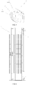
- air conditioner body 2. first air intake plate; 3. second air intake plate; 4. toothed fixing member; 5. push-pull mechanism; 6. mating portion; 7. first filter screen body; 8. second filter screen body; 9. air intake grid; 10. room.
- the air conditioner includes an air conditioner body 1, air intake plates, and a filter screen.
- the air conditioner body 1 is provided with an air inlet and an air outlet (not shown). Specifically, the air inlet and the air outlet are disposed on a housing of the air conditioner body 1.
- the air intake plate covers the air inlet.
- the air intake plate has an air intake grid 9 through which an external air flow enters the air conditioner body 1.
- the air intake grid 9 is also provided with a filter screen.
- the air intake plates are hingedly connected to the air conditioner body 1, so that the air intake plates are capable of being switched between an expanded state and a closed state.
- the filter screen is disposed between the air intake plates and the air inlet, and the filter screen is configured to filter air entering the air conditioner body 1 from the air intake grids 9.
- the air intake plates are designed to be a structure capable of expanding and closing.
- air is taken in through the entire air inlet instead of only from the air intake grids 9, increasing the air intake area.
- the air intake plates are in the closed state, the air intake area is reduced, but the amount of the intake air reaches a certain extent, without affecting the appearance of the air conditioner.
- the number of the air intake plates is two.
- the two air intake plates are respectively mounted on two sides of the air conditioner body 1.
- the two air intake plates are respectively a first air intake plate 2 and a second air intake plate 3, as shown in the drawings.
- One side of the first air intake plate 2 is hingedly connected to the air conditioner body 1 via a first rotating mechanism.
- Another side of the first air intake plate 2 is detachably connected to the air conditioner body 1 via a connecting mechanism.
- the first air intake plate 2 is capable of being expanded and closed through the first rotating mechanism, and a connection relationship between the first air intake plate 2 and the air conditioner body 1 can be ensured in the closed state, thereby improving the connection stability therebetween.
- the connecting mechanism is a snap-fit structure (not shown).
- the snap-fit structure includes a snap-fit clip and a snap-fit slot capable of mating with each other.
- the first air intake plate 2 is provided with one of the snap-fit clip and the snap-fit slot
- the air conditioner body 1 is provided with another of the snap-fit clip and the snap-fit slot. This configuration facilitates the connection and the disconnection between the air conditioner body 1 and the first air intake plate 2 and reduces the cost.
- the first rotating mechanism includes a gear (not shown) and a toothed fixing member 4 meshed with each other.
- the toothed fixing member has a plurality of teeth evenly spaced and distributed along a circular arc.
- the gear is mounted on the air conditioner body 1.
- the toothed fixing member 4 is disposed on an inner side of the first air intake plate 2.
- two toothed fixing members 4 are respectively disposed at an upper end and a lower end of the inner side of the first air intake plate 2.
- the air conditioner body 1 is provided with two gears mating with the two toothed fixing members 4.
- a central angle corresponding to the above-mentioned circular arc is preferably 90 degrees; that is, the circular arc corresponds to the quarter-circular plate as shown in FIG 1 .
- the plurality of teeth are evenly spaced and distributed on the circular arc surface of the quarter-circular plate.
- one side of the second air intake plate 3 is hingedly connected to the air conditioner body 1 via a second rotating mechanism (not shown).
- the second rotating mechanism can be a hinge.
- the hinges in various types can be used so long as the second air intake plate 3 can be rotated with respect to the air conditioner body 1. Since the structure of the hinge is well known in the related art, the specific structure thereof is not described in the present embodiment.
- another side of the second air intake plate 3 is connected to the air conditioner body 1 via a push-pull mechanism 5.
- the push-pull mechanism 5 is configured to make the other side of the second air intake plate 3 distant from and adjacent to the air conditioner body 1.
- the push-pull mechanism 5 includes a linear reciprocal moving mechanism.
- the linear reciprocal moving mechanism includes a fixing portion and a linear moving portion connected with each other.
- the fixing portion is mounted on the air conditioner body 1.
- the linear moving portion is connected to the second air intake plate 3.
- the linear reciprocal moving mechanism in various types and structures, such as an air cylinder, an electric cylinder, a ball bearing screw, and the like, can be used.
- the push-pull mechanism 5 is preferably a gear and a rack with simple structures.
- the gear is mounted on the air conditioner body 1, and the rack is respectively connected to the gear and the second air intake plate 3.
- a mating portion 6 is disposed on the second air intake plate 3 and mated with the rack.
- the rack is detachably connected to the mating portion 6.
- the gear of the first rotating mechanism and the gear of the linear reciprocal moving mechanism are different gears, and both can be driven to rotate by a driving mechanism (not shown).
- the driving mechanism is controlled by a control device.
- the driving mechanism can be actuated by the control device to drive the gears or one of the gears to rotate, thereby realizing the rotations of the first air intake plate 2 and the second air intake plate 3.
- the driving mechanism and the control device can be omitted, and thus the above-mentioned first air intake plate 2 and the second air intake plate 3 can be expanded manually; and in this case, both gears are driven gears.
- the structure of the filter screen is improved on the basis of the above-mentioned structure.
- a conventional filter screen is fixedly disposed between an air intake plate and an air inlet. Air enters the air conditioner through meshes of the conventional filter screen, so that the air entered the air conditioner from the air intake grid 9 is filtered.
- the diameters and the number of the meshes of the conventional filter screen are constant; thus, the air intake area is constant.
- the filter screen is designed to be variable, and the air intake area of the filter screen can be maximized by unfolding the folded filter screen.
- the first air intake plate 2 and the second air intake plate 3 are respectively located at two adjacent sides of the air conditioner body 1.
- the first air intake plate 2 and the second air intake plate 3 rotate in opposite directions during the expending. In other words, a distance between a position at which the first air intake plate 2 is hinged to the air conditioner body 1 and a position at which the second air intake plate 3 is hinged to the air conditioner body 1 is the farthest.
- the filter screen is designed to be a flexible filter screen, which is a filter screen with a variable and foldable structure.
- the filter screen includes three parts: a first filter screen body 7 connected to the air conditioner body 1 and the first air intake plate 2, a second filter screen body 8 connected to the first air intake plate 2 and the second air intake plate 3, and a third filter screen body (not shown) connected to the air conditioner body 1 and the second air intake plate 3.
- the first filter screen body 7, the second filter screen body 8, the third filter screen body, the first air intake plate 2, and the second air intake plate 3 jointly form a screen cover covering the air inlet, thereby maximizing the air intake area.
- the first filter screen body 7 includes a first portion located at an upper position and a second portion located at a lower position. Two opposite sides of the first portion are respectively connected to the air conditioner body 1 and an upper end of the first air intake plate 2. Two opposite sides of the second portion are respectively connected to the air conditioner body 1 and a lower end of the first air intake plate 2.
- the second filter screen body 8 includes a third portion located at an upper position and a fourth portion located at a lower position. Two opposite sides of the third portion are respectively connected to the air conditioner body 1 and an upper end of the second air intake plate 3. Two opposite sides of the fourth portion are respectively connected to the air conditioner body 1 and a lower end of the second air intake plate 3.
- the filter screen is unfolded when the first air intake plate 2 and the second air intake plate 3 are expanded, such that the filter screen is completely in an unfolded state, thereby increasing the air intake area.
- the first air intake plate 2 and the second air intake plate 3 can be closed to have the filter screen in the folded state without affecting the air intake effect.
- two air conditioners of the present embodiment are respectively mounted at two opposite corners of a room 10. There is a distance between the air inlet, at the side perpendicular to the wall-mounting surface, and a wall.
- the air conditioner When the air conditioner is turned on, both the first air intake plate 2 and the second air intake plate 3 are opened to a preset angle, and the flexible filter screen is in the unfold state.
- first, second or the like are used only for the purpose of description and should not be understood as indicating or implying a relative importance or implicitly indicating the number of technical features in question. Therefore, a feature which is defined by the term “first” or “second” may explicitly or implicitly include one or more of the features.
- a plurality of' means two or more, unless otherwise specifically stated.
- the terms “mount”, “connect”, “engage” and the like should be interpreted broadly, unless otherwise specified and limited.
- the “connect” can be “fixedly connect” “detachable connect”, “integrate with” or the like.
- the specific meaning of the above terms can be understood in the present invention based on the specific situations.
Landscapes
- Engineering & Computer Science (AREA)
- Chemical & Material Sciences (AREA)
- Combustion & Propulsion (AREA)
- Mechanical Engineering (AREA)
- General Engineering & Computer Science (AREA)
- Air Filters, Heat-Exchange Apparatuses, And Housings Of Air-Conditioning Units (AREA)
Applications Claiming Priority (2)
| Application Number | Priority Date | Filing Date | Title |
|---|---|---|---|
| CN201810928212.4A CN108954526B (zh) | 2018-08-15 | 2018-08-15 | 一种空调器 |
| PCT/CN2018/120957 WO2020034508A1 (zh) | 2018-08-15 | 2018-12-13 | 一种空调器 |
Publications (3)
| Publication Number | Publication Date |
|---|---|
| EP3779293A1 true EP3779293A1 (de) | 2021-02-17 |
| EP3779293A4 EP3779293A4 (de) | 2021-06-02 |
| EP3779293B1 EP3779293B1 (de) | 2025-09-03 |
Family
ID=64470123
Family Applications (1)
| Application Number | Title | Priority Date | Filing Date |
|---|---|---|---|
| EP18929878.9A Active EP3779293B1 (de) | 2018-08-15 | 2018-12-13 | Klimaanlage |
Country Status (3)
| Country | Link |
|---|---|
| EP (1) | EP3779293B1 (de) |
| CN (1) | CN108954526B (de) |
| WO (1) | WO2020034508A1 (de) |
Families Citing this family (2)
| Publication number | Priority date | Publication date | Assignee | Title |
|---|---|---|---|---|
| CN108954526B (zh) * | 2018-08-15 | 2023-11-10 | 珠海格力电器股份有限公司 | 一种空调器 |
| CN110553312A (zh) * | 2019-08-26 | 2019-12-10 | 珠海格力电器股份有限公司 | 一种空调及其控制方法 |
Family Cites Families (13)
| Publication number | Priority date | Publication date | Assignee | Title |
|---|---|---|---|---|
| JP3967029B2 (ja) * | 1999-02-15 | 2007-08-29 | 株式会社富士通ゼネラル | 空気調和機 |
| JP2001116345A (ja) * | 1999-10-20 | 2001-04-27 | Fujitsu General Ltd | 空気調和機 |
| JP2002061877A (ja) * | 2000-08-10 | 2002-02-28 | Hitachi Ltd | 空気調和機 |
| JP2003156225A (ja) * | 2001-11-20 | 2003-05-30 | Fujitsu General Ltd | 空気調和機 |
| JP2003207160A (ja) * | 2002-01-18 | 2003-07-25 | Fujitsu General Ltd | 空気調和機 |
| KR101214793B1 (ko) * | 2012-02-15 | 2012-12-24 | 삼우시스템 (주) | 에너지 절감형 공기조화기 |
| CN105650731B (zh) * | 2014-11-28 | 2018-08-31 | 青岛海尔空调器有限总公司 | 一种空调室内机及其气流控制方法 |
| CN105841327B (zh) * | 2016-05-13 | 2018-10-30 | 珠海格力电器股份有限公司 | 一种空调面板装置及空调设备 |
| CN105841324B (zh) * | 2016-05-13 | 2018-10-30 | 珠海格力电器股份有限公司 | 一种空调面板装置及空调设备 |
| CN206176696U (zh) * | 2016-09-26 | 2017-05-17 | 珠海格力电器股份有限公司 | 过滤网装置及空气调节设备 |
| CN108036420B (zh) * | 2017-12-08 | 2023-09-12 | 珠海格力电器股份有限公司 | 一种空调进风组件和空调器 |
| CN108954526B (zh) * | 2018-08-15 | 2023-11-10 | 珠海格力电器股份有限公司 | 一种空调器 |
| CN208901507U (zh) * | 2018-08-15 | 2019-05-24 | 珠海格力电器股份有限公司 | 一种空调器 |
-
2018
- 2018-08-15 CN CN201810928212.4A patent/CN108954526B/zh active Active
- 2018-12-13 WO PCT/CN2018/120957 patent/WO2020034508A1/zh not_active Ceased
- 2018-12-13 EP EP18929878.9A patent/EP3779293B1/de active Active
Also Published As
| Publication number | Publication date |
|---|---|
| EP3779293A4 (de) | 2021-06-02 |
| WO2020034508A1 (zh) | 2020-02-20 |
| CN108954526A (zh) | 2018-12-07 |
| EP3779293B1 (de) | 2025-09-03 |
| CN108954526B (zh) | 2023-11-10 |
Similar Documents
| Publication | Publication Date | Title |
|---|---|---|
| CN111508367B (zh) | 可折叠显示装置 | |
| JP3885845B2 (ja) | 空気調和機 | |
| EP3779293B1 (de) | Klimaanlage | |
| CN104279625A (zh) | 空调器 | |
| CN210569098U (zh) | 一种导风板驱动结构及空调室内机 | |
| JP2005106386A (ja) | 空気調和機の室内機 | |
| JPH1172265A (ja) | 空気調和機 | |
| CN103822342A (zh) | 面板运动机构及具有其的空调器室内机 | |
| CN203375543U (zh) | 空调器 | |
| CN213480389U (zh) | 一种挡风板组件、空调室内机及空调器 | |
| EP2180272B1 (de) | Stützstruktur für die frontplatte einer innenraumeinheit einer klimaanlage | |
| WO2024060716A1 (zh) | 新风装置及空调器室内机 | |
| KR20170046325A (ko) | 형상 가변형 필터프레임 및 이를 포함하는 공기청정기 | |
| CN208901507U (zh) | 一种空调器 | |
| CN217057715U (zh) | 隐藏式通风装置 | |
| JP2001174043A (ja) | 天井埋込型空気調和機 | |
| CN207763061U (zh) | 空调室内机及空调器 | |
| CN106642355B (zh) | 一种多功能壁挂式空调器 | |
| CN213777905U (zh) | 空调器室内机 | |
| CN213019915U (zh) | 空调器及其壳体 | |
| CN113137736A (zh) | 可转动连接机构及新风取暖器 | |
| CN111076289A (zh) | 一种室内机及空调器 | |
| CN107543247A (zh) | 空调室内机和空调器 | |
| JP3440969B2 (ja) | 空気調和機 | |
| KR20090020962A (ko) | 덕트형 공기조화기 |
Legal Events
| Date | Code | Title | Description |
|---|---|---|---|
| STAA | Information on the status of an ep patent application or granted ep patent |
Free format text: STATUS: THE INTERNATIONAL PUBLICATION HAS BEEN MADE |
|
| PUAI | Public reference made under article 153(3) epc to a published international application that has entered the european phase |
Free format text: ORIGINAL CODE: 0009012 |
|
| STAA | Information on the status of an ep patent application or granted ep patent |
Free format text: STATUS: REQUEST FOR EXAMINATION WAS MADE |
|
| 17P | Request for examination filed |
Effective date: 20201111 |
|
| AK | Designated contracting states |
Kind code of ref document: A1 Designated state(s): AL AT BE BG CH CY CZ DE DK EE ES FI FR GB GR HR HU IE IS IT LI LT LU LV MC MK MT NL NO PL PT RO RS SE SI SK SM TR |
|
| AX | Request for extension of the european patent |
Extension state: BA ME |
|
| A4 | Supplementary search report drawn up and despatched |
Effective date: 20210506 |
|
| RIC1 | Information provided on ipc code assigned before grant |
Ipc: F24F 1/00 20190101AFI20210429BHEP Ipc: F24F 13/14 20060101ALI20210429BHEP Ipc: F24F 13/28 20060101ALI20210429BHEP Ipc: F24F 1/0007 20190101ALI20210429BHEP Ipc: F24F 1/0073 20190101ALI20210429BHEP Ipc: F24F 13/08 20060101ALI20210429BHEP |
|
| DAV | Request for validation of the european patent (deleted) | ||
| DAX | Request for extension of the european patent (deleted) | ||
| STAA | Information on the status of an ep patent application or granted ep patent |
Free format text: STATUS: EXAMINATION IS IN PROGRESS |
|
| 17Q | First examination report despatched |
Effective date: 20230403 |
|
| P01 | Opt-out of the competence of the unified patent court (upc) registered |
Effective date: 20230530 |
|
| GRAP | Despatch of communication of intention to grant a patent |
Free format text: ORIGINAL CODE: EPIDOSNIGR1 |
|
| STAA | Information on the status of an ep patent application or granted ep patent |
Free format text: STATUS: GRANT OF PATENT IS INTENDED |
|
| INTG | Intention to grant announced |
Effective date: 20250512 |
|
| GRAS | Grant fee paid |
Free format text: ORIGINAL CODE: EPIDOSNIGR3 |
|
| GRAA | (expected) grant |
Free format text: ORIGINAL CODE: 0009210 |
|
| STAA | Information on the status of an ep patent application or granted ep patent |
Free format text: STATUS: THE PATENT HAS BEEN GRANTED |
|
| AK | Designated contracting states |
Kind code of ref document: B1 Designated state(s): AL AT BE BG CH CY CZ DE DK EE ES FI FR GB GR HR HU IE IS IT LI LT LU LV MC MK MT NL NO PL PT RO RS SE SI SK SM TR |
|
| REG | Reference to a national code |
Ref country code: GB Ref legal event code: FG4D |
|
| REG | Reference to a national code |
Ref country code: CH Ref legal event code: EP |
|
| REG | Reference to a national code |
Ref country code: DE Ref legal event code: R096 Ref document number: 602018085358 Country of ref document: DE |
|
| REG | Reference to a national code |
Ref country code: IE Ref legal event code: FG4D |
|
| REG | Reference to a national code |
Ref country code: NL Ref legal event code: MP Effective date: 20250903 |
|
| PGFP | Annual fee paid to national office [announced via postgrant information from national office to epo] |
Ref country code: DE Payment date: 20251212 Year of fee payment: 8 |
|
| PG25 | Lapsed in a contracting state [announced via postgrant information from national office to epo] |
Ref country code: NO Free format text: LAPSE BECAUSE OF FAILURE TO SUBMIT A TRANSLATION OF THE DESCRIPTION OR TO PAY THE FEE WITHIN THE PRESCRIBED TIME-LIMIT Effective date: 20251203 |
|
| REG | Reference to a national code |
Ref country code: LT Ref legal event code: MG9D |
|
| PG25 | Lapsed in a contracting state [announced via postgrant information from national office to epo] |
Ref country code: FI Free format text: LAPSE BECAUSE OF FAILURE TO SUBMIT A TRANSLATION OF THE DESCRIPTION OR TO PAY THE FEE WITHIN THE PRESCRIBED TIME-LIMIT Effective date: 20250903 |
|
| PG25 | Lapsed in a contracting state [announced via postgrant information from national office to epo] |
Ref country code: HR Free format text: LAPSE BECAUSE OF FAILURE TO SUBMIT A TRANSLATION OF THE DESCRIPTION OR TO PAY THE FEE WITHIN THE PRESCRIBED TIME-LIMIT Effective date: 20250903 |
|
| PG25 | Lapsed in a contracting state [announced via postgrant information from national office to epo] |
Ref country code: GR Free format text: LAPSE BECAUSE OF FAILURE TO SUBMIT A TRANSLATION OF THE DESCRIPTION OR TO PAY THE FEE WITHIN THE PRESCRIBED TIME-LIMIT Effective date: 20251204 |
|
| PG25 | Lapsed in a contracting state [announced via postgrant information from national office to epo] |
Ref country code: SE Free format text: LAPSE BECAUSE OF FAILURE TO SUBMIT A TRANSLATION OF THE DESCRIPTION OR TO PAY THE FEE WITHIN THE PRESCRIBED TIME-LIMIT Effective date: 20250903 |
|
| PG25 | Lapsed in a contracting state [announced via postgrant information from national office to epo] |
Ref country code: LV Free format text: LAPSE BECAUSE OF FAILURE TO SUBMIT A TRANSLATION OF THE DESCRIPTION OR TO PAY THE FEE WITHIN THE PRESCRIBED TIME-LIMIT Effective date: 20250903 |
|
| PG25 | Lapsed in a contracting state [announced via postgrant information from national office to epo] |
Ref country code: BG Free format text: LAPSE BECAUSE OF FAILURE TO SUBMIT A TRANSLATION OF THE DESCRIPTION OR TO PAY THE FEE WITHIN THE PRESCRIBED TIME-LIMIT Effective date: 20250903 Ref country code: PL Free format text: LAPSE BECAUSE OF FAILURE TO SUBMIT A TRANSLATION OF THE DESCRIPTION OR TO PAY THE FEE WITHIN THE PRESCRIBED TIME-LIMIT Effective date: 20250903 |
|
| PG25 | Lapsed in a contracting state [announced via postgrant information from national office to epo] |
Ref country code: RS Free format text: LAPSE BECAUSE OF FAILURE TO SUBMIT A TRANSLATION OF THE DESCRIPTION OR TO PAY THE FEE WITHIN THE PRESCRIBED TIME-LIMIT Effective date: 20251203 |
|
| PG25 | Lapsed in a contracting state [announced via postgrant information from national office to epo] |
Ref country code: ES Free format text: LAPSE BECAUSE OF FAILURE TO SUBMIT A TRANSLATION OF THE DESCRIPTION OR TO PAY THE FEE WITHIN THE PRESCRIBED TIME-LIMIT Effective date: 20250903 |
|
| REG | Reference to a national code |
Ref country code: AT Ref legal event code: MK05 Ref document number: 1833452 Country of ref document: AT Kind code of ref document: T Effective date: 20250903 |
|
| PG25 | Lapsed in a contracting state [announced via postgrant information from national office to epo] |
Ref country code: NL Free format text: LAPSE BECAUSE OF FAILURE TO SUBMIT A TRANSLATION OF THE DESCRIPTION OR TO PAY THE FEE WITHIN THE PRESCRIBED TIME-LIMIT Effective date: 20250903 |
|
| PG25 | Lapsed in a contracting state [announced via postgrant information from national office to epo] |
Ref country code: SM Free format text: LAPSE BECAUSE OF FAILURE TO SUBMIT A TRANSLATION OF THE DESCRIPTION OR TO PAY THE FEE WITHIN THE PRESCRIBED TIME-LIMIT Effective date: 20250903 |
|
| PG25 | Lapsed in a contracting state [announced via postgrant information from national office to epo] |
Ref country code: AT Free format text: LAPSE BECAUSE OF FAILURE TO SUBMIT A TRANSLATION OF THE DESCRIPTION OR TO PAY THE FEE WITHIN THE PRESCRIBED TIME-LIMIT Effective date: 20250903 |
|
| PG25 | Lapsed in a contracting state [announced via postgrant information from national office to epo] |
Ref country code: RO Free format text: LAPSE BECAUSE OF FAILURE TO SUBMIT A TRANSLATION OF THE DESCRIPTION OR TO PAY THE FEE WITHIN THE PRESCRIBED TIME-LIMIT Effective date: 20250903 Ref country code: IT Free format text: LAPSE BECAUSE OF FAILURE TO SUBMIT A TRANSLATION OF THE DESCRIPTION OR TO PAY THE FEE WITHIN THE PRESCRIBED TIME-LIMIT Effective date: 20250903 |
|
| PG25 | Lapsed in a contracting state [announced via postgrant information from national office to epo] |
Ref country code: IS Free format text: LAPSE BECAUSE OF FAILURE TO SUBMIT A TRANSLATION OF THE DESCRIPTION OR TO PAY THE FEE WITHIN THE PRESCRIBED TIME-LIMIT Effective date: 20260103 |
|
| PG25 | Lapsed in a contracting state [announced via postgrant information from national office to epo] |
Ref country code: CZ Free format text: LAPSE BECAUSE OF FAILURE TO SUBMIT A TRANSLATION OF THE DESCRIPTION OR TO PAY THE FEE WITHIN THE PRESCRIBED TIME-LIMIT Effective date: 20250903 Ref country code: PT Free format text: LAPSE BECAUSE OF FAILURE TO SUBMIT A TRANSLATION OF THE DESCRIPTION OR TO PAY THE FEE WITHIN THE PRESCRIBED TIME-LIMIT Effective date: 20260105 |
|
| PG25 | Lapsed in a contracting state [announced via postgrant information from national office to epo] |
Ref country code: SK Free format text: LAPSE BECAUSE OF FAILURE TO SUBMIT A TRANSLATION OF THE DESCRIPTION OR TO PAY THE FEE WITHIN THE PRESCRIBED TIME-LIMIT Effective date: 20250903 Ref country code: EE Free format text: LAPSE BECAUSE OF FAILURE TO SUBMIT A TRANSLATION OF THE DESCRIPTION OR TO PAY THE FEE WITHIN THE PRESCRIBED TIME-LIMIT Effective date: 20250903 |