EP3779252A1 - Multiport valve for water quality analyzer - Google Patents
Multiport valve for water quality analyzer Download PDFInfo
- Publication number
- EP3779252A1 EP3779252A1 EP19778397.0A EP19778397A EP3779252A1 EP 3779252 A1 EP3779252 A1 EP 3779252A1 EP 19778397 A EP19778397 A EP 19778397A EP 3779252 A1 EP3779252 A1 EP 3779252A1
- Authority
- EP
- European Patent Office
- Prior art keywords
- valve head
- rotor
- water quality
- stator
- quality analyzer
- Prior art date
- Legal status (The legal status is an assumption and is not a legal conclusion. Google has not performed a legal analysis and makes no representation as to the accuracy of the status listed.)
- Granted
Links
Images


Classifications
-
- F—MECHANICAL ENGINEERING; LIGHTING; HEATING; WEAPONS; BLASTING
- F16—ENGINEERING ELEMENTS AND UNITS; GENERAL MEASURES FOR PRODUCING AND MAINTAINING EFFECTIVE FUNCTIONING OF MACHINES OR INSTALLATIONS; THERMAL INSULATION IN GENERAL
- F16K—VALVES; TAPS; COCKS; ACTUATING-FLOATS; DEVICES FOR VENTING OR AERATING
- F16K11/00—Multiple-way valves, e.g. mixing valves; Pipe fittings incorporating such valves
- F16K11/02—Multiple-way valves, e.g. mixing valves; Pipe fittings incorporating such valves with all movable sealing faces moving as one unit
- F16K11/06—Multiple-way valves, e.g. mixing valves; Pipe fittings incorporating such valves with all movable sealing faces moving as one unit comprising only sliding valves, i.e. sliding closure elements
- F16K11/072—Multiple-way valves, e.g. mixing valves; Pipe fittings incorporating such valves with all movable sealing faces moving as one unit comprising only sliding valves, i.e. sliding closure elements with pivoted closure members
- F16K11/074—Multiple-way valves, e.g. mixing valves; Pipe fittings incorporating such valves with all movable sealing faces moving as one unit comprising only sliding valves, i.e. sliding closure elements with pivoted closure members with flat sealing faces
- F16K11/0743—Multiple-way valves, e.g. mixing valves; Pipe fittings incorporating such valves with all movable sealing faces moving as one unit comprising only sliding valves, i.e. sliding closure elements with pivoted closure members with flat sealing faces with both the supply and the discharge passages being on one side of the closure plates
-
- F—MECHANICAL ENGINEERING; LIGHTING; HEATING; WEAPONS; BLASTING
- F16—ENGINEERING ELEMENTS AND UNITS; GENERAL MEASURES FOR PRODUCING AND MAINTAINING EFFECTIVE FUNCTIONING OF MACHINES OR INSTALLATIONS; THERMAL INSULATION IN GENERAL
- F16K—VALVES; TAPS; COCKS; ACTUATING-FLOATS; DEVICES FOR VENTING OR AERATING
- F16K25/00—Details relating to contact between valve members and seats
- F16K25/005—Particular materials for seats or closure elements
-
- G—PHYSICS
- G01—MEASURING; TESTING
- G01N—INVESTIGATING OR ANALYSING MATERIALS BY DETERMINING THEIR CHEMICAL OR PHYSICAL PROPERTIES
- G01N30/00—Investigating or analysing materials by separation into components using adsorption, absorption or similar phenomena or using ion-exchange, e.g. chromatography or field flow fractionation
- G01N30/02—Column chromatography
- G01N30/04—Preparation or injection of sample to be analysed
- G01N30/16—Injection
- G01N30/20—Injection using a sampling valve
-
- G—PHYSICS
- G01—MEASURING; TESTING
- G01N—INVESTIGATING OR ANALYSING MATERIALS BY DETERMINING THEIR CHEMICAL OR PHYSICAL PROPERTIES
- G01N30/00—Investigating or analysing materials by separation into components using adsorption, absorption or similar phenomena or using ion-exchange, e.g. chromatography or field flow fractionation
- G01N30/02—Column chromatography
- G01N30/88—Integrated analysis systems specially adapted therefor, not covered by a single one of the groups G01N30/04 - G01N30/86
-
- G—PHYSICS
- G01—MEASURING; TESTING
- G01N—INVESTIGATING OR ANALYSING MATERIALS BY DETERMINING THEIR CHEMICAL OR PHYSICAL PROPERTIES
- G01N35/00—Automatic analysis not limited to methods or materials provided for in any single one of groups G01N1/00 - G01N33/00; Handling materials therefor
- G01N35/10—Devices for transferring samples or any liquids to, in, or from, the analysis apparatus, e.g. suction devices, injection devices
- G01N35/1095—Devices for transferring samples or any liquids to, in, or from, the analysis apparatus, e.g. suction devices, injection devices for supplying the samples to flow-through analysers
- G01N35/1097—Devices for transferring samples or any liquids to, in, or from, the analysis apparatus, e.g. suction devices, injection devices for supplying the samples to flow-through analysers characterised by the valves
-
- F—MECHANICAL ENGINEERING; LIGHTING; HEATING; WEAPONS; BLASTING
- F16—ENGINEERING ELEMENTS AND UNITS; GENERAL MEASURES FOR PRODUCING AND MAINTAINING EFFECTIVE FUNCTIONING OF MACHINES OR INSTALLATIONS; THERMAL INSULATION IN GENERAL
- F16K—VALVES; TAPS; COCKS; ACTUATING-FLOATS; DEVICES FOR VENTING OR AERATING
- F16K31/00—Actuating devices; Operating means; Releasing devices
- F16K31/02—Actuating devices; Operating means; Releasing devices electric; magnetic
- F16K31/04—Actuating devices; Operating means; Releasing devices electric; magnetic using a motor
- F16K31/041—Actuating devices; Operating means; Releasing devices electric; magnetic using a motor for rotating valves
-
- G—PHYSICS
- G01—MEASURING; TESTING
- G01N—INVESTIGATING OR ANALYSING MATERIALS BY DETERMINING THEIR CHEMICAL OR PHYSICAL PROPERTIES
- G01N30/00—Investigating or analysing materials by separation into components using adsorption, absorption or similar phenomena or using ion-exchange, e.g. chromatography or field flow fractionation
- G01N30/02—Column chromatography
- G01N30/04—Preparation or injection of sample to be analysed
- G01N30/16—Injection
- G01N30/20—Injection using a sampling valve
- G01N2030/201—Injection using a sampling valve multiport valves, i.e. having more than two ports
-
- G—PHYSICS
- G01—MEASURING; TESTING
- G01N—INVESTIGATING OR ANALYSING MATERIALS BY DETERMINING THEIR CHEMICAL OR PHYSICAL PROPERTIES
- G01N30/00—Investigating or analysing materials by separation into components using adsorption, absorption or similar phenomena or using ion-exchange, e.g. chromatography or field flow fractionation
- G01N30/02—Column chromatography
- G01N30/04—Preparation or injection of sample to be analysed
- G01N30/16—Injection
- G01N30/20—Injection using a sampling valve
- G01N2030/202—Injection using a sampling valve rotary valves
Definitions
- the present invention relates to a multiport valve used for a water quality analyzer.
- processing such as, e.g., collection of a sample, suction of a reagent, addition of a reagent to a sample, delivery of a sample to an oxidation reaction section, and delivery of the sample to a measurement section, is performed using a syringe pump.
- the processing is performed by switching the flow paths communicating with the syringe pump by a multiport valve (see Patent Document 1).
- a highly corrosive reagent such as, e.g., strong acid and strong alkali, is frequently used in a water quality analyzer. Therefore, all of the components configuring the water quality analyzer that come into contact with a reagent must be configured by a material having corrosion resistance against a reagent. For this reason, in a multiport value for a water quality analyzer is configured such that the metallic portions do not come into contact with a reagent.
- a multiport valve is composed of a valve body, a valve head, a rotor, a stator, etc.
- the valve head is a metallic member attached to the tip of the valve body.
- the valve head is provided with a plurality of female threaded holes for securing piping.
- the stator is assembled to the valve head and has flow paths therein to communicate with piping connected to the female threaded holes of the valve head.
- the rotor includes a groove for communicating between flow paths formed in the stator to switch the flow paths of the stator by rotating while sliding with the stator.
- Patent Document 1 Japanese Unexamined Patent Application Publication No. 2013-015387
- the piping In a multiple port valve used for a water quality analyzer, to prevent highly corrosive chemicals from coming into contact with a metallic valve head, the piping is fixed to the female threads in a state in which the tip end of the piping is pressed against the stator with a strong force to seal the connecting part between the flow path and the stator. With the structure, the tip ends of the plurality of piping are pressed against the stator from a plurality of directions. In particular, when the stresses are uneven, the stator may be deformed or the ferrule attached to the tip of the piping may be deformed, resulting in a liquid leakage in the multiple port value.
- the metallic valve head When a liquid leakage occurs in the multiport valve, the metallic valve head may corrode or rust, causing problems such as poor water sampling, crystallization of the reagent, and sticking of joint components. This may cause the stator to stick to the valve head. In the worst case, it becomes impossible to replace the stator.
- the present invention aims to prevent a liquid leakage in a multiport valve due to stresses being applied from a plurality of directions to a stator.
- a multiport valve used for a water quality analyzer according to the present invention is provided with:
- the tip end of the piping is not configured to be pressed against the stator.
- the valve head is configured by a material having corrosion resistance and piping is connected to the flow paths provided in the valve head.
- it is not configured such that the ends of piping are pressed against the stator from a plurality of directions.
- stator fixed to the valve head side may be interposed between the flat surface of the rotor formed with the groove and the connection surface of the valve head.
- the sliding surfaces thereof may sometime be polished and adhered to each other, resulting in adhesion of the rotor and the stator. Therefore, the rotor and the stator may be configured by materials different in hardness from each other. This configuration can prevent the adhesion of the rotor and the stator. Further, one of the rotor and the stator is configured by a material softer than the other, so that the one configured by a softer material is elastically deformed, which improves the sealing performance between them.
- no stator may be interposed between the valve head and the rotor. That is, the flat surface of the rotor in which the groove is formed may be in direct contact with the connection surface of the valve head.
- the rotor may be configured by a resin material softer than the valve head. With this configuration, the rotor is more easily worn than the valve head due to the sliding between the valve head and the rotor, which can suppress the wear of the valve head.
- a fluorine resin may be used as the material of the valve head.
- fluorine resin polytetrafluoroethylene (PTFE) and polychlorotrifluoroethylene (PCTFE) can be exemplified.
- the stator fixed to the valve head side may be interposed between the flat surface of the rotor in which the groove is formed and the connection surface of the valve head.
- at least one of the rotor and the stator may be configured by a resin material. In this configuration, the resin material is easily elastically deformed, so the sealing between the rotor and the stator can be enhanced.
- the material of the rotor may be a fluorine resin.
- the material of the stator may be a fluorine resin
- the valve head is configured by a material having corrosion resistance and piping is connected to the flow paths provided in the valve head. Therefore, the stator is not configured to be pressed by the tip ends of piping from several directions, and consequently, no liquid leakage occurs due to such a configuration.
- a multiport valve 1 for a water quality analyzer is provided with a valve body 2 and a valve head 4.
- the valve head 4 is attached to the tip end of the valve body 2.
- a plurality of ports 6 is provided on the outer surface of the valve head 4.
- Each port 6 is a female screw hole for connecting piping to the outer surface of the valve head 4.
- the plurality of ports 6 is in communication with the respective flow paths 8 formed in the valve head 4, and the ends of the flow paths 8 are arranged on the flat surface 4a of the valve head 4 forming the rearmost surface of the inner space of the valve body 2.
- the flat surface 4a of the valve head 4 forms a connection surface in which the ends of the flow paths 8 communicating with the respective ports 6 are arranged on the same plane.
- the stator 10 is attached to the flat surface 4a of the valve head 4.
- the stator 10 is interposed between the valve head 4 and the rotor 14, which will be described later, to slide with the rotor 10.
- the stator 10 has through-holes 12 at positions corresponding to the ends of the flow paths 8 provided on the flat surface 4a.
- the rotor 14 is held at the tip end portion 18a of the rotor shaft 18.
- the rotor 14 has a flat surface facing the flat surface 4a of the valve head 4, and a groove 16 for communicating between the ends of the respective flow paths 8 is formed on the flat surface.
- the rotor 14 is provided a flat surface in which the groove 16 is formed, and the flat surface is in contact with the stator 12. The rotor 14 rotates in accordance with the rotation of the rotor shaft 18 while sliding with the stator 12 to switch between the ends of the flow paths 8 to communicate them.
- the rotor shaft 18 is biased toward the valve head 4 side by an elastic member such as a coil spring, thereby constantly pressing the rotor 14 against the stator 10.
- the rotor shaft 18 is rotated by a stepping motor 22.
- the rotor shaft 18 and the stepping motor 22 form a drive mechanism for rotating the rotor 14.
- the valve head 4, the stator 10, and the rotor 14 are configured by a material having corrosion resistance against a reagent that can be used in a water quality analyzer.
- a material having corrosion resistance against a reagent that can be used in a water quality analyzer.
- PPS polyphenylene sulfide
- PEEK polyether ether ketone
- PTFE polytetrafluoroethylene
- PCTFE polychlorotrifluoroethylene
- valve head 4 is configured by a corrosion resistance material as described above, and therefore it is possible to flow chemicals with high corrosion resistance, such as, e.g., strong acid and strong alkali, through the flow paths 8 in the valve head 4. Therefore, there is no need to seal by pressing piping through which those chemicals flow against a member (e.g., stator) different from the valve head 4.
- a corrosion resistance material as described above, and therefore it is possible to flow chemicals with high corrosion resistance, such as, e.g., strong acid and strong alkali, through the flow paths 8 in the valve head 4. Therefore, there is no need to seal by pressing piping through which those chemicals flow against a member (e.g., stator) different from the valve head 4.
- the sealing surfaces in the valve 1 are limited to the plane between the valve head 4 and the stator 10 and the plane between the stator 10 and the rotor 14, so that stress is applied only in a direction perpendicular to the sealing surfaces. That is, the fastening force of the joint for connecting piping acts only on the valve head 4, and no stress is applied from directions other than the direction perpendicular to the sealing surface in the valve 1.
- stator 10 and the rotor 14 are preferably configured by materials different in hardness (e.g., ceramics and PEEK, etc.). With this configuration, the member configured by a softer material is elastically deformed, so the sealing between the stator 10 and the rotor 14 is improved.
- the rotor 14 is a replaceable consumable member, and therefore the rotor 14 is more preferably configured by a material (e.g., PEEK) softer than the stator 10.
- the rotor 14 may be in direct contact with the valve head 4.
- the rotor 14 is preferably configured by a material softer than the valve head 4.
- the valve head 4 may be configured by PPS and the rotor 14 may be configured by PEEK.
- the sealing surface in the valve 1' is only the surface between the valve head 4 and the rotor 14, and the fastening force of the joint for connecting piping acts only on the valve head 4. Therefore, the stress is applied only in a direction perpendicular to the sealing surface of the valve 1'.
Landscapes
- Engineering & Computer Science (AREA)
- General Engineering & Computer Science (AREA)
- Chemical & Material Sciences (AREA)
- Physics & Mathematics (AREA)
- Health & Medical Sciences (AREA)
- Life Sciences & Earth Sciences (AREA)
- Analytical Chemistry (AREA)
- Biochemistry (AREA)
- General Health & Medical Sciences (AREA)
- General Physics & Mathematics (AREA)
- Immunology (AREA)
- Pathology (AREA)
- Mechanical Engineering (AREA)
- Multiple-Way Valves (AREA)
- Valve Housings (AREA)
Abstract
Description
- The present invention relates to a multiport valve used for a water quality analyzer.
- In a water quality analyzer, processing, such as, e.g., collection of a sample, suction of a reagent, addition of a reagent to a sample, delivery of a sample to an oxidation reaction section, and delivery of the sample to a measurement section, is performed using a syringe pump. The processing is performed by switching the flow paths communicating with the syringe pump by a multiport valve (see Patent Document 1).
- A highly corrosive reagent, such as, e.g., strong acid and strong alkali, is frequently used in a water quality analyzer. Therefore, all of the components configuring the water quality analyzer that come into contact with a reagent must be configured by a material having corrosion resistance against a reagent. For this reason, in a multiport value for a water quality analyzer is configured such that the metallic portions do not come into contact with a reagent.
- Specifically, a multiport valve is composed of a valve body, a valve head, a rotor, a stator, etc. The valve head is a metallic member attached to the tip of the valve body. The valve head is provided with a plurality of female threaded holes for securing piping. The stator is assembled to the valve head and has flow paths therein to communicate with piping connected to the female threaded holes of the valve head. The rotor includes a groove for communicating between flow paths formed in the stator to switch the flow paths of the stator by rotating while sliding with the stator.
- Patent Document 1: Japanese Unexamined Patent Application Publication No.
2013-015387 - In a multiple port valve used for a water quality analyzer, to prevent highly corrosive chemicals from coming into contact with a metallic valve head, the piping is fixed to the female threads in a state in which the tip end of the piping is pressed against the stator with a strong force to seal the connecting part between the flow path and the stator. With the structure, the tip ends of the plurality of piping are pressed against the stator from a plurality of directions. In particular, when the stresses are uneven, the stator may be deformed or the ferrule attached to the tip of the piping may be deformed, resulting in a liquid leakage in the multiple port value.
- When a liquid leakage occurs in the multiport valve, the metallic valve head may corrode or rust, causing problems such as poor water sampling, crystallization of the reagent, and sticking of joint components. This may cause the stator to stick to the valve head. In the worst case, it becomes impossible to replace the stator.
- Therefore, the present invention aims to prevent a liquid leakage in a multiport valve due to stresses being applied from a plurality of directions to a stator.
- A multiport valve used for a water quality analyzer according to the present invention is provided with:
- a valve head having a plurality of ports for receiving pipings for connections therebetween, the ports being provided on an outer surface of the valve head, the valve head including a connection surface in which ends of flow paths communicating with the respective ports are arranged in the same plane, the valve head being made by a resin material having corrosion resistance against a chemical used in the water quality analyzer;
- a rotor having a flat surface provided with a groove for switching a connection state between the ends of the flow paths arranged on the connection surface, the flat surface being arranged so as to face the connection surface; and
- a drive mechanism configured to rotate the rotor.
- That is, in the multiport valve for a water quality analyzer according to the present invention, the tip end of the piping is not configured to be pressed against the stator. The valve head is configured by a material having corrosion resistance and piping is connected to the flow paths provided in the valve head. In short, in the multiport valve for a water quality analyzer according to the present invention, it is not configured such that the ends of piping are pressed against the stator from a plurality of directions.
- In the present invention, the stator fixed to the valve head side may be interposed between the flat surface of the rotor formed with the groove and the connection surface of the valve head.
- In the above-described case, in cases where the rotor and the stator are configured by the same material, the sliding surfaces thereof may sometime be polished and adhered to each other, resulting in adhesion of the rotor and the stator. Therefore, the rotor and the stator may be configured by materials different in hardness from each other. This configuration can prevent the adhesion of the rotor and the stator. Further, one of the rotor and the stator is configured by a material softer than the other, so that the one configured by a softer material is elastically deformed, which improves the sealing performance between them.
- In the present invention, no stator may be interposed between the valve head and the rotor. That is, the flat surface of the rotor in which the groove is formed may be in direct contact with the connection surface of the valve head.
- In the above-described case, the rotor may be configured by a resin material softer than the valve head. With this configuration, the rotor is more easily worn than the valve head due to the sliding between the valve head and the rotor, which can suppress the wear of the valve head.
- A fluorine resin may be used as the material of the valve head. As the fluorine resin, polytetrafluoroethylene (PTFE) and polychlorotrifluoroethylene (PCTFE) can be exemplified.
- The stator fixed to the valve head side may be interposed between the flat surface of the rotor in which the groove is formed and the connection surface of the valve head. In that case, at least one of the rotor and the stator may be configured by a resin material. In this configuration, the resin material is easily elastically deformed, so the sealing between the rotor and the stator can be enhanced.
- In the above-described cases, the material of the rotor may be a fluorine resin.
- Further, the material of the stator may be a fluorine resin
- In the multiport valve for a water quality analyzer according to the present invention, the valve head is configured by a material having corrosion resistance and piping is connected to the flow paths provided in the valve head. Therefore, the stator is not configured to be pressed by the tip ends of piping from several directions, and consequently, no liquid leakage occurs due to such a configuration.
-
-
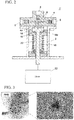
FIG. 1 is a cross-sectional configuration diagram showing an example of a multiport valve for a water quality analyzer. -
FIG. 2 is a cross-sectional diagram showing another example of a multiport valve for a water quality analyzer. -
FIG. 3 is an image showing a state of flow paths when a valve head made of PPS has been used for a long time. -
FIG. 4 shows a state of flow paths when a valve head made of PCTFE has been used for a long time. - Hereinafter, an embodiment of a multiport valve for a water quality analyzer will be described with reference to the attached drawings.
- A
multiport valve 1 for a water quality analyzer according to one example is provided with avalve body 2 and avalve head 4. Thevalve head 4 is attached to the tip end of thevalve body 2. A plurality ofports 6 is provided on the outer surface of thevalve head 4. Eachport 6 is a female screw hole for connecting piping to the outer surface of thevalve head 4. The plurality ofports 6 is in communication with therespective flow paths 8 formed in thevalve head 4, and the ends of theflow paths 8 are arranged on theflat surface 4a of thevalve head 4 forming the rearmost surface of the inner space of thevalve body 2. Theflat surface 4a of thevalve head 4 forms a connection surface in which the ends of theflow paths 8 communicating with therespective ports 6 are arranged on the same plane. - The
stator 10 is attached to theflat surface 4a of thevalve head 4. Thestator 10 is interposed between thevalve head 4 and therotor 14, which will be described later, to slide with therotor 10. Thestator 10 has through-holes 12 at positions corresponding to the ends of theflow paths 8 provided on theflat surface 4a. - In the
valve body 2, therotor 14 is held at thetip end portion 18a of therotor shaft 18. Therotor 14 has a flat surface facing theflat surface 4a of thevalve head 4, and agroove 16 for communicating between the ends of therespective flow paths 8 is formed on the flat surface. Therotor 14 is provided a flat surface in which thegroove 16 is formed, and the flat surface is in contact with thestator 12. Therotor 14 rotates in accordance with the rotation of therotor shaft 18 while sliding with thestator 12 to switch between the ends of theflow paths 8 to communicate them. - The
rotor shaft 18 is biased toward thevalve head 4 side by an elastic member such as a coil spring, thereby constantly pressing therotor 14 against thestator 10. Therotor shaft 18 is rotated by a steppingmotor 22. Therotor shaft 18 and the steppingmotor 22 form a drive mechanism for rotating therotor 14. - In the
multiport valve 1 for a water quality analyzer of this example, at least thevalve head 4, thestator 10, and therotor 14 are configured by a material having corrosion resistance against a reagent that can be used in a water quality analyzer. As such materials, PPS (polyphenylene sulfide), PEEK (polyether ether ketone), PTFE (polytetrafluoroethylene), PCTFE (polychlorotrifluoroethylene), and ceramics, can be exemplified. - In particular, by using a fluorine resin, such as, e.g., PTFE and PCTFE, as the corrosion resistance material, it is possible to prevent flow path closure due to rust, dissolution and/or erosion of the material. The present inventor verified the durability of the
valve head 4 when PPS was used as the material for thevalve head 4 and when PCTFE was used as the material for thevalve head 4. When thevalve head 4 made of PPS was used for a long time, as shown inFIG. 3 , blockage of a flow path formed in thevalve head 4 occurred. In contrast, even when thevalve head 4 made of PCTFE was used for a long time, as shown inFIG. 4 , no blockage of the flow paths formed in thevalve head 4 occurred. Therefore, when a fluorine resin, such as, e.g., PCTFE , is used as the material for thestator 10 and therotor 10 in addition to thevalve head 4, it is possible to effectively prevent flow path blockage due to melting and/or erosion of a material. - In particular, the
valve head 4 is configured by a corrosion resistance material as described above, and therefore it is possible to flow chemicals with high corrosion resistance, such as, e.g., strong acid and strong alkali, through theflow paths 8 in thevalve head 4. Therefore, there is no need to seal by pressing piping through which those chemicals flow against a member (e.g., stator) different from thevalve head 4. - With such a structure, the sealing surfaces in the
valve 1 are limited to the plane between thevalve head 4 and thestator 10 and the plane between thestator 10 and therotor 14, so that stress is applied only in a direction perpendicular to the sealing surfaces. That is, the fastening force of the joint for connecting piping acts only on thevalve head 4, and no stress is applied from directions other than the direction perpendicular to the sealing surface in thevalve 1. - Note that the
stator 10 and therotor 14 are preferably configured by materials different in hardness (e.g., ceramics and PEEK, etc.). With this configuration, the member configured by a softer material is elastically deformed, so the sealing between thestator 10 and therotor 14 is improved. In particular, therotor 14 is a replaceable consumable member, and therefore therotor 14 is more preferably configured by a material (e.g., PEEK) softer than thestator 10. - Note that as in the multiport valve 1' for a water quality analyzer shown in
FIG. 2 , without interposing a stator between thevalve head 4 and therotor 14, therotor 14 may be in direct contact with thevalve head 4. In this case, in order to suppress the wear of thevalve head 4, therotor 14 is preferably configured by a material softer than thevalve head 4. For example, thevalve head 4 may be configured by PPS and therotor 14 may be configured by PEEK. - With the configuration as shown in
FIG. 2 , the sealing surface in the valve 1' is only the surface between thevalve head 4 and therotor 14, and the fastening force of the joint for connecting piping acts only on thevalve head 4. Therefore, the stress is applied only in a direction perpendicular to the sealing surface of the valve 1'. -
- 1, 1':
- Multiport valve for a water quality analyzer
- 2:
- Valve body
- 4:
- Valve head
- 6:
- Port
- 8:
- Flow path
- 10:
- Stator
- 12:
- Through-hole
- 14:
- Rotor
- 16:
- Groove
- 18:
- Rotor shaft
- 20:
- Elastic member
- 22:
- Stepping motor
Claims (9)
- A multiport valve used for a water quality analyzer comprising:a valve head having a plurality of ports for receiving pipings for connections therebetween, the ports being provided on an outer surface of the valve head, the valve head including a connection surface in which ends of flow paths communicating with the respective ports are arranged in the same plane, the valve head being made of a resin material having corrosion resistance against a chemical used in the water quality analyzer;a rotor having a flat surface provided with a groove for switching a connection state between the ends of the flow paths arranged on the connection surface, the flat surface being arranged so as to face the connection surface; anda drive mechanism configured to rotate the rotor.
- The multiport valve used for a water quality analyzer as recited in claim 1, further comprising:
a stator fixed to the valve head, the stator being interposed between the flat surface of the rotor formed with the groove and the connection surface of the valve head. - The multiport valve used for a water quality analyzer as recited in claim 2,
wherein the rotor and the stator are configured by materials different in hardness from each other. - The multiport valve used for a water quality analyzer as recited in claim 1,
wherein the flat surface of the rotor formed with the groove is in contact with the connection surface of the valve head. - The multiport valve used for a water quality analyzer as recited in claim 4,
wherein the rotor is configured by a resin material softer than the valve head. - The multiport valve used for a water quality analyzer as recited in claim 1,
wherein the material of the valve head is a fluorine resin. - The multiport valve used for a water quality analyzer as recited in claim 6, further comprising:a stator fixed to the valve head, the stator being interposed between the flat surface of the rotor formed with the groove and the connection surface of the valve head, andwherein at least one of the rotor and the stator is configured by a resin material.
- The multiport valve used for a water quality analyzer as recited in claim 7,
wherein the material of the rotor is a fluorine resin. - The multiport valve used for a water quality analyzer as recited in claim 7,
wherein the material of the stator is a fluorine resin.
Applications Claiming Priority (2)
| Application Number | Priority Date | Filing Date | Title |
|---|---|---|---|
| PCT/JP2018/012409 WO2019186690A1 (en) | 2018-03-27 | 2018-03-27 | Multiport valve for water quality analyzer |
| PCT/JP2019/008352 WO2019188011A1 (en) | 2018-03-27 | 2019-03-04 | Multiport valve for water quality analyzer |
Publications (3)
| Publication Number | Publication Date |
|---|---|
| EP3779252A1 true EP3779252A1 (en) | 2021-02-17 |
| EP3779252A4 EP3779252A4 (en) | 2022-01-05 |
| EP3779252B1 EP3779252B1 (en) | 2026-05-06 |
Family
ID=68059024
Family Applications (1)
| Application Number | Title | Priority Date | Filing Date |
|---|---|---|---|
| EP19778397.0A Active EP3779252B1 (en) | 2018-03-27 | 2019-03-04 | Multiport valve for water quality analyzer |
Country Status (6)
| Country | Link |
|---|---|
| US (1) | US11781660B2 (en) |
| EP (1) | EP3779252B1 (en) |
| JP (2) | JPWO2019188011A1 (en) |
| CN (1) | CN111886431B (en) |
| TW (1) | TWI746931B (en) |
| WO (2) | WO2019186690A1 (en) |
Families Citing this family (5)
| Publication number | Priority date | Publication date | Assignee | Title |
|---|---|---|---|---|
| US20200362973A1 (en) * | 2019-05-14 | 2020-11-19 | Tecan Trading Ag | Non-sticking rotary valve |
| CN112483679A (en) * | 2020-11-18 | 2021-03-12 | 深圳垦拓流体控制有限公司 | Rotary cutting valve with long service life structure |
| US12297931B2 (en) | 2021-02-08 | 2025-05-13 | Schivo Medical Limited | Centering electronic rotary valve |
| US12320441B1 (en) * | 2021-02-08 | 2025-06-03 | Schivo Medical Limited | Centering electronic rotary valve |
| JP7659472B2 (en) * | 2021-08-27 | 2025-04-09 | 株式会社アルバック | Rotary valve for refrigerator |
Family Cites Families (44)
| Publication number | Priority date | Publication date | Assignee | Title |
|---|---|---|---|---|
| US3297053A (en) * | 1963-12-30 | 1967-01-10 | Carle Instr Inc | Selector valve |
| US3384118A (en) * | 1965-10-23 | 1968-05-21 | Pneumo Dynamics Corp | Fuel control valve |
| US3426796A (en) * | 1966-10-14 | 1969-02-11 | Pneumo Dynamics Corp | Control valve pressurizing port |
| GB1195913A (en) * | 1967-04-13 | 1970-06-24 | Bp Chem Int Ltd | Multiport Valve. |
| US3533295A (en) * | 1968-12-30 | 1970-10-13 | Phillips Petroleum Co | Sample valve |
| JPS4825722Y1 (en) * | 1970-05-11 | 1973-07-26 | ||
| US3752167A (en) * | 1970-07-07 | 1973-08-14 | Shimadzu Corp | Fluid switching device |
| JPS5545511B2 (en) * | 1971-08-05 | 1980-11-18 | ||
| US4156437A (en) * | 1978-02-21 | 1979-05-29 | The Perkin-Elmer Corporation | Computer controllable multi-port valve |
| US4243071A (en) * | 1978-08-23 | 1981-01-06 | Altex Scientific, Inc. | Sample injection valve |
| US4444066A (en) * | 1981-06-29 | 1984-04-24 | Beckman Instruments, Inc. | High pressure sample injector valve |
| JPH01307575A (en) * | 1988-06-03 | 1989-12-12 | Shimadzu Corp | Change-over valve |
| US5419208A (en) * | 1993-01-29 | 1995-05-30 | Upchurch Scientific, Inc. | Multiport selection valve |
| US5441071A (en) | 1994-05-04 | 1995-08-15 | Mclane Research Laboratories, Inc. | Automated water sample collecting system |
| US5465748A (en) * | 1994-05-24 | 1995-11-14 | Millipore Corporation | Sanitizable slider diaphragm valve |
| US6202698B1 (en) * | 1997-06-18 | 2001-03-20 | Valco Instruments Company, Inc. | Multiple port diaphragm valve |
| JP4067685B2 (en) * | 1999-03-26 | 2008-03-26 | 山善株式会社 | Injection device |
| US6267143B1 (en) * | 1999-06-29 | 2001-07-31 | Upchurch Scientific, Inc. | Selection valve with ferrule cluster |
| US6431202B1 (en) | 1999-12-01 | 2002-08-13 | Calgon Carbon Corporation | Fluid-directing multiport rotary valve |
| JP4182331B2 (en) | 2002-08-20 | 2008-11-19 | Nok株式会社 | Multiway valve |
| JP4019372B2 (en) * | 2003-06-18 | 2007-12-12 | 王子製紙株式会社 | Liquid sample injection device |
| JP4764348B2 (en) * | 2003-11-10 | 2011-08-31 | ウオーターズ・テクノロジーズ・コーポレイシヨン | Device and method for controlling fluid flow in a conduit |
| CN2830828Y (en) * | 2005-03-25 | 2006-10-25 | 黄兴耀 | Full-automatic rotating shaft type multi-way control valve |
| CN2854257Y (en) | 2005-11-24 | 2007-01-03 | 江苏江分电分析仪器有限公司 | Multipurpose corrosion-resistant valve |
| US8016264B2 (en) * | 2006-05-02 | 2011-09-13 | Teijin Pharma Limited | Rotary-valve and adsorption separation system |
| JP4825722B2 (en) | 2007-04-27 | 2011-11-30 | アイシン・エィ・ダブリュ株式会社 | Route guidance system, navigation device, and route guidance method |
| CN101896750A (en) * | 2008-02-14 | 2010-11-24 | 株式会社岛津制作所 | flow switching valve |
| JP2010271029A (en) * | 2009-04-23 | 2010-12-02 | Sumitomo Heavy Ind Ltd | Cooling storage type refrigerating machine, method of manufacturing rotary valve for the cooling storage type refrigerating machine and method of manufacturing the cooling storage type refrigerating machine |
| US8438910B2 (en) * | 2009-05-07 | 2013-05-14 | Agilent Technologies, Inc. | Shear valve with DLC comprising multi-layer coated member |
| CA2767364C (en) * | 2009-07-13 | 2017-05-16 | Idex Health & Science Llc | Rotary shear valve assembly with hard-on-hard seal surfaces |
| DE102011000104B4 (en) * | 2011-01-12 | 2013-02-07 | Dionex Softron Gmbh | High pressure switching valve for high performance liquid chromatography |
| JP5659968B2 (en) | 2011-07-04 | 2015-01-28 | 株式会社島津製作所 | Water quality analyzer |
| US9200715B2 (en) | 2011-11-11 | 2015-12-01 | Shimadzu Corporation | Passage-switching valve |
| US9671376B2 (en) * | 2011-12-26 | 2017-06-06 | Shimadzu Corporation | Flow path switching valve |
| DE102012107380B4 (en) * | 2012-08-10 | 2017-03-09 | Dionex Softron Gmbh | Switching valve, in particular high-pressure switching valve for high-performance liquid chromatography |
| US9063114B2 (en) * | 2012-08-10 | 2015-06-23 | Dionex Softron Gmbh | Switching valve for liquid chromatography |
| US9388930B2 (en) | 2012-09-14 | 2016-07-12 | Idex Health & Science Llc | Fluidic interface valve assembly with elastomeric ferrule device |
| CN202992266U (en) * | 2012-11-16 | 2013-06-12 | 安徽省碧水电子技术有限公司 | Multi-channel corrosion-resisting high-temperature-resisting rotary valve |
| JP5999252B2 (en) | 2013-03-11 | 2016-09-28 | 株式会社島津製作所 | Flow path switching valve |
| TWI534381B (en) | 2013-04-25 | 2016-05-21 | 和正豐科技股份有限公司 | Method and structure for preventing pull-off of a fluor-resin tube fitting |
| WO2016049004A1 (en) | 2014-09-23 | 2016-03-31 | Idex Health & Science Llc | Spring-less multi-position micro-fluidic valve assembly |
| TWI666398B (en) * | 2016-07-13 | 2019-07-21 | 台達電子國際(新加坡)私人有限公司 | Fluid control device |
| JP6965502B2 (en) | 2016-08-30 | 2021-11-10 | 株式会社島津製作所 | Water quality analyzer |
| CN106382391A (en) | 2016-11-04 | 2017-02-08 | 上海化工研究院 | Three-way planar reversing valve |
-
2018
- 2018-03-27 WO PCT/JP2018/012409 patent/WO2019186690A1/en not_active Ceased
-
2019
- 2019-02-13 TW TW108104832A patent/TWI746931B/en active
- 2019-03-04 US US17/041,375 patent/US11781660B2/en active Active
- 2019-03-04 CN CN201980018606.9A patent/CN111886431B/en active Active
- 2019-03-04 JP JP2020509750A patent/JPWO2019188011A1/en active Pending
- 2019-03-04 EP EP19778397.0A patent/EP3779252B1/en active Active
- 2019-03-04 WO PCT/JP2019/008352 patent/WO2019188011A1/en not_active Ceased
-
2022
- 2022-11-24 JP JP2022187457A patent/JP7655300B2/en active Active
Also Published As
| Publication number | Publication date |
|---|---|
| TW201942501A (en) | 2019-11-01 |
| JP7655300B2 (en) | 2025-04-02 |
| US11781660B2 (en) | 2023-10-10 |
| CN111886431A (en) | 2020-11-03 |
| JP2023022160A (en) | 2023-02-14 |
| EP3779252A4 (en) | 2022-01-05 |
| WO2019186690A1 (en) | 2019-10-03 |
| EP3779252B1 (en) | 2026-05-06 |
| JPWO2019188011A1 (en) | 2021-02-12 |
| US20210123537A1 (en) | 2021-04-29 |
| WO2019188011A1 (en) | 2019-10-03 |
| TWI746931B (en) | 2021-11-21 |
| CN111886431B (en) | 2022-09-09 |
Similar Documents
| Publication | Publication Date | Title |
|---|---|---|
| US11781660B2 (en) | Multiport valve for water quality analyzer | |
| US8322374B2 (en) | Channel switching valve | |
| US7553139B2 (en) | Progressing cavity pump with wobble stator and magnetic drive | |
| JP2008215494A (en) | Flow path switching valve | |
| EP2610493B1 (en) | Stator seal structure for single-shaft eccentric screw pump | |
| US20100276617A1 (en) | Flow channel switching valve | |
| US20160082439A1 (en) | Spring-less multi-position micro-fluidic valve assembly | |
| US12158452B2 (en) | Flow passage switching valve and liquid chromatograph having the same | |
| US11371502B2 (en) | Sealed drive for connecting progressive cavity pump rotors to universal joints | |
| US20160025690A1 (en) | Flow path switching valve | |
| EP3369973B1 (en) | Regulating valve | |
| WO2012173908A1 (en) | Rotary shear valve with a two-pin drive shaft for liquid chromatography applications | |
| US20140271264A1 (en) | Piston pump drive train anti-backlash | |
| CN110578675B (en) | Peristaltic pump | |
| WO2003014602A1 (en) | A mechanical seal without elastomers | |
| KR100419308B1 (en) | Single Axial Eccentric Screw Pump | |
| US20170089335A1 (en) | A gear pump having through-shaft bearing weepage control | |
| KR101852324B1 (en) | Centrifugal pump |
Legal Events
| Date | Code | Title | Description |
|---|---|---|---|
| STAA | Information on the status of an ep patent application or granted ep patent |
Free format text: STATUS: THE INTERNATIONAL PUBLICATION HAS BEEN MADE |
|
| PUAI | Public reference made under article 153(3) epc to a published international application that has entered the european phase |
Free format text: ORIGINAL CODE: 0009012 |
|
| STAA | Information on the status of an ep patent application or granted ep patent |
Free format text: STATUS: REQUEST FOR EXAMINATION WAS MADE |
|
| 17P | Request for examination filed |
Effective date: 20201017 |
|
| AK | Designated contracting states |
Kind code of ref document: A1 Designated state(s): AL AT BE BG CH CY CZ DE DK EE ES FI FR GB GR HR HU IE IS IT LI LT LU LV MC MK MT NL NO PL PT RO RS SE SI SK SM TR |
|
| AX | Request for extension of the european patent |
Extension state: BA ME |
|
| DAV | Request for validation of the european patent (deleted) | ||
| DAX | Request for extension of the european patent (deleted) | ||
| A4 | Supplementary search report drawn up and despatched |
Effective date: 20211203 |
|
| RIC1 | Information provided on ipc code assigned before grant |
Ipc: F16K 11/074 20060101ALI20211129BHEP Ipc: G01N 35/10 20060101ALI20211129BHEP Ipc: G01N 30/20 20060101ALI20211129BHEP Ipc: F16K 25/00 20060101ALI20211129BHEP Ipc: F16K 11/06 20060101AFI20211129BHEP |
|
| STAA | Information on the status of an ep patent application or granted ep patent |
Free format text: STATUS: EXAMINATION IS IN PROGRESS |
|
| 17Q | First examination report despatched |
Effective date: 20230626 |
|
| GRAP | Despatch of communication of intention to grant a patent |
Free format text: ORIGINAL CODE: EPIDOSNIGR1 |
|
| STAA | Information on the status of an ep patent application or granted ep patent |
Free format text: STATUS: GRANT OF PATENT IS INTENDED |
|
| INTG | Intention to grant announced |
Effective date: 20250724 |
|
| GRAJ | Information related to disapproval of communication of intention to grant by the applicant or resumption of examination proceedings by the epo deleted |
Free format text: ORIGINAL CODE: EPIDOSDIGR1 |
|
| STAA | Information on the status of an ep patent application or granted ep patent |
Free format text: STATUS: EXAMINATION IS IN PROGRESS |
|
| GRAP | Despatch of communication of intention to grant a patent |
Free format text: ORIGINAL CODE: EPIDOSNIGR1 |
|
| STAA | Information on the status of an ep patent application or granted ep patent |
Free format text: STATUS: GRANT OF PATENT IS INTENDED |
|
| INTC | Intention to grant announced (deleted) | ||
| INTG | Intention to grant announced |
Effective date: 20251204 |
|
| GRAS | Grant fee paid |
Free format text: ORIGINAL CODE: EPIDOSNIGR3 |
|
| GRAA | (expected) grant |
Free format text: ORIGINAL CODE: 0009210 |
|
| STAA | Information on the status of an ep patent application or granted ep patent |
Free format text: STATUS: THE PATENT HAS BEEN GRANTED |