EP3779209B1 - Self-propelled working machine on a solid floor surface with hydraulic unit mounted on a chassis - Google Patents
Self-propelled working machine on a solid floor surface with hydraulic unit mounted on a chassis Download PDFInfo
- Publication number
- EP3779209B1 EP3779209B1 EP19405013.4A EP19405013A EP3779209B1 EP 3779209 B1 EP3779209 B1 EP 3779209B1 EP 19405013 A EP19405013 A EP 19405013A EP 3779209 B1 EP3779209 B1 EP 3779209B1
- Authority
- EP
- European Patent Office
- Prior art keywords
- container
- fluid
- machine according
- closure plate
- hydraulic
- Prior art date
- Legal status (The legal status is an assumption and is not a legal conclusion. Google has not performed a legal analysis and makes no representation as to the accuracy of the status listed.)
- Active
Links
Images


Classifications
-
- F—MECHANICAL ENGINEERING; LIGHTING; HEATING; WEAPONS; BLASTING
- F15—FLUID-PRESSURE ACTUATORS; HYDRAULICS OR PNEUMATICS IN GENERAL
- F15B—SYSTEMS ACTING BY MEANS OF FLUIDS IN GENERAL; FLUID-PRESSURE ACTUATORS, e.g. SERVOMOTORS; DETAILS OF FLUID-PRESSURE SYSTEMS, NOT OTHERWISE PROVIDED FOR
- F15B1/00—Installations or systems with accumulators; Supply reservoir or sump assemblies
- F15B1/26—Supply reservoir or sump assemblies
-
- B—PERFORMING OPERATIONS; TRANSPORTING
- B66—HOISTING; LIFTING; HAULING
- B66F—HOISTING, LIFTING, HAULING OR PUSHING, NOT OTHERWISE PROVIDED FOR, e.g. DEVICES WHICH APPLY A LIFTING OR PUSHING FORCE DIRECTLY TO THE SURFACE OF A LOAD
- B66F9/00—Devices for lifting or lowering bulky or heavy goods for loading or unloading purposes
- B66F9/06—Devices for lifting or lowering bulky or heavy goods for loading or unloading purposes movable, with their loads, on wheels or the like, e.g. fork-lift trucks
- B66F9/075—Constructional features or details
- B66F9/07513—Details concerning the chassis
- B66F9/07518—Fuel or oil tank arrangements
-
- B—PERFORMING OPERATIONS; TRANSPORTING
- B66—HOISTING; LIFTING; HAULING
- B66F—HOISTING, LIFTING, HAULING OR PUSHING, NOT OTHERWISE PROVIDED FOR, e.g. DEVICES WHICH APPLY A LIFTING OR PUSHING FORCE DIRECTLY TO THE SURFACE OF A LOAD
- B66F9/00—Devices for lifting or lowering bulky or heavy goods for loading or unloading purposes
- B66F9/06—Devices for lifting or lowering bulky or heavy goods for loading or unloading purposes movable, with their loads, on wheels or the like, e.g. fork-lift trucks
- B66F9/075—Constructional features or details
- B66F9/07572—Propulsion arrangements
-
- F—MECHANICAL ENGINEERING; LIGHTING; HEATING; WEAPONS; BLASTING
- F04—POSITIVE - DISPLACEMENT MACHINES FOR LIQUIDS; PUMPS FOR LIQUIDS OR ELASTIC FLUIDS
- F04B—POSITIVE-DISPLACEMENT MACHINES FOR LIQUIDS; PUMPS
- F04B17/00—Pumps characterised by combination with, or adaptation to, specific driving engines or motors
- F04B17/03—Pumps characterised by combination with, or adaptation to, specific driving engines or motors driven by electric motors
-
- F—MECHANICAL ENGINEERING; LIGHTING; HEATING; WEAPONS; BLASTING
- F04—POSITIVE - DISPLACEMENT MACHINES FOR LIQUIDS; PUMPS FOR LIQUIDS OR ELASTIC FLUIDS
- F04B—POSITIVE-DISPLACEMENT MACHINES FOR LIQUIDS; PUMPS
- F04B23/00—Pumping installations or systems
- F04B23/02—Pumping installations or systems having reservoirs
- F04B23/025—Pumping installations or systems having reservoirs the pump being located directly adjacent the reservoir
- F04B23/028—Pumping installations or systems having reservoirs the pump being located directly adjacent the reservoir the pump being mounted on top of the reservoir
-
- F—MECHANICAL ENGINEERING; LIGHTING; HEATING; WEAPONS; BLASTING
- F15—FLUID-PRESSURE ACTUATORS; HYDRAULICS OR PNEUMATICS IN GENERAL
- F15B—SYSTEMS ACTING BY MEANS OF FLUIDS IN GENERAL; FLUID-PRESSURE ACTUATORS, e.g. SERVOMOTORS; DETAILS OF FLUID-PRESSURE SYSTEMS, NOT OTHERWISE PROVIDED FOR
- F15B21/00—Common features of fluid actuator systems; Fluid-pressure actuator systems or details thereof, not covered by any other group of this subclass
- F15B21/005—Filling or draining of fluid systems
-
- F—MECHANICAL ENGINEERING; LIGHTING; HEATING; WEAPONS; BLASTING
- F15—FLUID-PRESSURE ACTUATORS; HYDRAULICS OR PNEUMATICS IN GENERAL
- F15B—SYSTEMS ACTING BY MEANS OF FLUIDS IN GENERAL; FLUID-PRESSURE ACTUATORS, e.g. SERVOMOTORS; DETAILS OF FLUID-PRESSURE SYSTEMS, NOT OTHERWISE PROVIDED FOR
- F15B21/00—Common features of fluid actuator systems; Fluid-pressure actuator systems or details thereof, not covered by any other group of this subclass
- F15B21/04—Special measures taken in connection with the properties of the fluid
- F15B21/042—Controlling the temperature of the fluid
- F15B21/0423—Cooling
-
- F—MECHANICAL ENGINEERING; LIGHTING; HEATING; WEAPONS; BLASTING
- F15—FLUID-PRESSURE ACTUATORS; HYDRAULICS OR PNEUMATICS IN GENERAL
- F15B—SYSTEMS ACTING BY MEANS OF FLUIDS IN GENERAL; FLUID-PRESSURE ACTUATORS, e.g. SERVOMOTORS; DETAILS OF FLUID-PRESSURE SYSTEMS, NOT OTHERWISE PROVIDED FOR
- F15B21/00—Common features of fluid actuator systems; Fluid-pressure actuator systems or details thereof, not covered by any other group of this subclass
- F15B21/04—Special measures taken in connection with the properties of the fluid
- F15B21/048—Arrangements for compressed air preparation, e.g. comprising air driers, air condensers, filters, lubricators or pressure regulators
-
- F—MECHANICAL ENGINEERING; LIGHTING; HEATING; WEAPONS; BLASTING
- F15—FLUID-PRESSURE ACTUATORS; HYDRAULICS OR PNEUMATICS IN GENERAL
- F15B—SYSTEMS ACTING BY MEANS OF FLUIDS IN GENERAL; FLUID-PRESSURE ACTUATORS, e.g. SERVOMOTORS; DETAILS OF FLUID-PRESSURE SYSTEMS, NOT OTHERWISE PROVIDED FOR
- F15B2211/00—Circuits for servomotor systems
- F15B2211/20—Fluid pressure source, e.g. accumulator or variable axial piston pump
- F15B2211/205—Systems with pumps
- F15B2211/20507—Type of prime mover
- F15B2211/20515—Electric motor
-
- F—MECHANICAL ENGINEERING; LIGHTING; HEATING; WEAPONS; BLASTING
- F15—FLUID-PRESSURE ACTUATORS; HYDRAULICS OR PNEUMATICS IN GENERAL
- F15B—SYSTEMS ACTING BY MEANS OF FLUIDS IN GENERAL; FLUID-PRESSURE ACTUATORS, e.g. SERVOMOTORS; DETAILS OF FLUID-PRESSURE SYSTEMS, NOT OTHERWISE PROVIDED FOR
- F15B2211/00—Circuits for servomotor systems
- F15B2211/60—Circuit components or control therefor
- F15B2211/615—Filtering means
-
- F—MECHANICAL ENGINEERING; LIGHTING; HEATING; WEAPONS; BLASTING
- F15—FLUID-PRESSURE ACTUATORS; HYDRAULICS OR PNEUMATICS IN GENERAL
- F15B—SYSTEMS ACTING BY MEANS OF FLUIDS IN GENERAL; FLUID-PRESSURE ACTUATORS, e.g. SERVOMOTORS; DETAILS OF FLUID-PRESSURE SYSTEMS, NOT OTHERWISE PROVIDED FOR
- F15B2211/00—Circuits for servomotor systems
- F15B2211/60—Circuit components or control therefor
- F15B2211/62—Cooling or heating means
Definitions
- the invention relates to a work machine that is self-propelled on a solid ground surface and has a hydraulic unit mounted on a chassis for operating the work machine by pumped hydraulic fluid as a power transmission means, the hydraulic unit consisting of a liquid tank provided for receiving the hydraulic fluid and at least one for removing it from the latter and returning the hydraulic fluid via a liquid return line of the hydraulic fluid into the liquid tank, preferably electrically driven feed pump, as well as a switching valve arrangement that can be controlled between the feed pump and at least one rotary and / or linearly driven consumer of the work machine, which are arranged on the liquid tank, the liquid tank being formed from a container that is open at the top is and the feed pump and the switching valve arrangement connected to it, the connecting lines of the unit components and a liquid filling opening are arranged as a unit on a closure plate that closes the container opening, the closure plate being formed from a metallic material, preferably from structural steel, and the container being formed in one piece.
- the motor pump unit is attached directly/immediately to the tank via a tank opening
- the return filter which has an elongated filter housing for a filter element with a filter cartridge, is inserted into a tank opening intended for it in the tank and has a hose connection and an outlet opening , wherein the filter element is arranged in the flow path between the hose connection and the outlet opening, and a return hose that connects the motor pump unit and the hose connection within the tank.
- Liquid tanks made of metal primarily structural steel, are known as hydraulic units and are formed by welding with feed pumps, valve blocks and filters as well as a filler neck.
- a built-up hydraulic unit with a sheet metal tank made of structural steel is relatively heavy and, with complex chassis and body shapes such as those formed on the outer contour of a vehicle, for example in the wheel arch area, very expensive to produce.
- a welded liquid tank is susceptible to corrosion, particularly after damage to the surface, and stresses around the weld seams lead to leaks.
- a plastic tank has a significant disadvantage when integrating attached aggregation components, such as motors, pumps and valve combinations, especially since the required fastening structures, for example insert frames, can only be implemented in narrow dimensions due to the different expansion coefficients of metal and plastic, because temperature fluctuations lead to a reduction in stability and loss of rigidity , lead to leaks between the insert frames and the plastic tank and weaken the existing strength.
- WO 2017/005338 A1 discloses a hydraulic unit, the electric motor and the hydraulic pump of which are flanged to a first structural unit serving as a supporting device.
- the latter is formed by a metallic molded body which is accommodated in a seat which is formed in the top of a second structural unit formed by a plate-like plastic body.
- This forms a kind of tank cap for the upper open side of the tank of the hydraulic unit.
- the material of the tank is not specified.
- WO 99/13229 A1 discloses an embodiment of a hydraulic unit in which the tank is open at the top and closed by a tank cap. The material of these two parts is not specified.
- the tank is made in one piece from plastic with a connection opening for a housing part of the pump.
- the tank made of plastic is formed in one piece, with the pump lines being connected through a circular pipe socket formed on the upper top wall of the tank.
- DE 10 2016 101 662 A1 relates to a flow line for a pump device of a motor vehicle with flow elements arranged in the flow line. Also revealed US 6,116,454 A a hydraulic oil tank for a work machine with a flow guide element arranged in the tank.
- the present invention has set itself the task of developing a hydraulic unit that has a high level of reliability in use, allows easy assembly when setting up the affected unit components and proves to be robust over a long period of use, and it is intended the susceptibility to wear and the risk of leakage can be largely eliminated.
- the object was achieved in that the container is manufactured with plastic using the rotational molding or injection molding process and the container is box-shaped and has a container end shaped according to a section of a wheel arch of the mobile work machine.
- the solution according to the invention is intended to provide the hydraulic unit with a high quality of functions and greater precision among the aggregation components as well as simple assembly of the unit components built on the closure plate.
- the unit components can be assembled away from the container and tested for function and then installed together on the closure plate of the liquid tank in the container or removed from it individually or together for maintenance and/or repair.
- the hydraulic fluid flowing back into the fluid tank after use is returned via a fluid return line, which is preferably provided with a return filter at the end.
- an outer wall of the container can form a supplementary part of the vehicle body (body part) of the work machine.
- the closure plate which also serves as a cover for the container, is made of a metallic material, preferably made of structural steel, for example a sheet steel or the like, for high stability of the hydraulic unit on the chassis of the work machine and provides a large-area, torsion-resistant connection to the liquid container.
- the upper end or The connecting end of the container to the closure plate is formed by a fastening device provided for sealing between the container and the closure plate.
- the open edge of which can be reinforced for a tight connection to the attached closure plate.
- the feed pump(s), which form a unit and form a unit, the switching valve arrangement, the liquid filter protruding into the liquid tank, the connecting lines and screw connections and other fittings as well as a liquid filler neck are advantageously attached to the closure plate and thus facilitate assembly and disassembly as a unit maintenance work and controls.
- the container is designed in one piece, but also fulfills its relevant function and task in a two-part design.
- the container can also be made from plastic using a different process, which proves to be a durable material and resistant to corrosion and impact situations.
- the liquid filling opening is preferably formed by a filling and venting filter which projects into the liquid-free space of the liquid tank and is attached to the underside of the closure plate.
- the container is box-like and is equipped with a container end shaped like a section of a wheel arch of the mobile work machine, so that it can be attached to the chassis in a space- and weight-saving manner and is easily accessible from the outside.
- a filling and venting filter is preferably arranged in the liquid tank above a certain liquid level so that it can optimally develop its effect.
- the container below the feed pump(s) immersed in the liquid has a container constriction that connects the container into two container spaces, which protrudes from the bottom of the container upwards into the container and ends approximately below the aggregate components, whereby in the container spaces a mixing of the stored cooled liquid with the returned warmer liquid quantity can be achieved.
- the container constriction is formed by at least one flow threshold that distinguishes/divides the liquid tank into a liquid return flow and a container space assigned to the liquid suction, through which a laminar mixture of the returned and the resting hydraulic liquid is achieved.
- the flow threshold(s) can be provided on a rear wall of a cavity placed in the container and thus promote a heat balancing effect.
- a suction opening of the suction line connected to the feed pump(s) is advantageously arranged in the container space at a lower liquid temperature than in the other container space of the liquid tank.
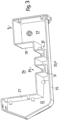
- Fig. 1 shows a spatially represented hydraulic unit 2 built on a chassis of a self-propelled work machine 1 for generating work force/performance by means of a circulating hydraulic fluid.
- the hydraulic unit 2 consists of a container 3 intended to hold the hydraulic fluid, made of plastic, for example made of fiber-crosslinked polyethylene, polyamide or similar material, which is produced in a rotational molding or injection molding process, advantageously in more complex shapes that are closer to the purpose, more cost-effective and with lower weight and appropriate rigidity compared to a tank made of welded steel sheets.
- At least one feed pump 11, 12 is provided, which is arranged inside the fluid tank and is screwed onto a preferably flat closure plate 6 which is fastened to the upper opening of the container 3 and forms a closed fluid tank 5.
- This serves to position and fasten the actuating elements or components of the hydraulic unit 2 as a furnishing unit and can be placed on the container edge 7 defining the upper opening of the container 3 and fastened to hold the liquid tank 5 tightly.
- screws 8 or comparable similar fastening elements are provided, which are anchored at the front in the container edge 7.
- FIG. 1 and 2 show Fig. 1 and 2 a switching valve arrangement 13 attached to the closure plate 6 for controlling the hydraulic fluid or of the unit components, and opposite, laterally offset from the electric motor of the feed pumps 11, 12, a filling and venting filter 14, which projects into the liquid tank 5 and is designed for filling the latter, and a service cover 15, respectively.
- closing flange to which a return filter 20 which projects into the liquid tank 5 and is connected to the liquid return line 18 is attached.
- the closure plate 6 which is made of a metallic material, for example structural steel, offers a high level of rigidity over the plate extension and, together with the container 3, exerts robust stability and rigidity on the liquid tank 5. In terms of manufacturing technology, the closure plate does not pose any high demands.
- the flat extension/extension of the closure plate 6 allows a simple design and arrangement of the unit components, the construction of which can be carried out on the closure plate 6 using simple machine elements and work equipment.
- the shape of the closure plate 6 is suitable for a tight connection with the container 3 at the container edge 7.
- the unit components can be easily detached/removed from the locking plate 6 for maintenance, repair or replacement.
- the container 3 is made in one piece and is manufactured with plastic using rotational molding or an injection molding process.
- a container 3 made of sheet steel can also be used.
- the container 3 is box-shaped so that it can be installed in a space-saving manner on/into the chassis 16 of the self-propelled machine and is easily accessible.
- the container 3 of the liquid tank 5 is in the immediate vicinity of a wheel arch 17 of a rigid or a steerable front or rear axle of the mobile work machine 1, based on the geometry of the wheel arch shape. concentric to the wheel axis ( Fig. 2 ).
- the unit components 11, 12, 13, 14, 15 as well as the liquid lines of the system can be individually removed from the closure plate 6, be it for maintenance, repair or replacement.
- the return filter 20 is preferably part of the equipment of the hydraulic unit 2 and is attached to the closure plate 6 so that it projects into the liquid tank 5, the liquid return line 18, preferably at its end opening into the liquid tank 5, having an outlet opening, for example below the liquid level 19, is trained.
- the return filter 20, equipped with a filter cartridge, is connected at the upper end to the liquid return line 18 (see Fig. 2 ).
- the in Fig. 1 The illustrated service cover (flange) 15 for replacing or maintaining the return filter 20 lies above an invisible filling opening, which is usually extended by a filler neck projecting into the liquid tank 5.
- the liquid tank 5 is divided into two unseparated container spaces 22, 23 by a constriction provided in the container 3 by means of a threshold arrangement 21.
- a threshold arrangement 21 This is in the Fig. 2 and 3 It can be seen that a lower wall part of the rear container wall 24 is offset towards the front wall 25 of the container 3 and extends to a height below the aggregate components or the liquid level 19, and thus forms a cavity 26.
- the side walls 27, 28 and roof-like ceiling elements 29, 30 complete the cavity 26, on the back of which, container wall part 24, a pair of laterally spaced, strip-like flow thresholds 31, 32 protruding against the front container wall 25 are arranged.
- the hydraulic fluid flowing back from the working devices of the working machine 1 into the liquid tank 5 only flows to a small part of the container space 22 via the threshold device 31, 32 into the laterally adjacent container space 23 which is assigned to the suction line 34 of the feed pump (s) 11, 12.
- the larger part flows into the upper common area and mixes with the oil calmed in the liquid tank 5 and cools down slightly, with the suction opening 34 being arranged in the container space 23 with the lower liquid temperature.
- the flow thresholds 31, 32 are attached parallel to each other and running upwards on the back of the rear container wall 24.
- Fig. 2 Additionally, it conveys the routing of the hydraulic fluid among the unit components and the consumers (not shown).
- the already mentioned suction line 34 carries the hydraulic fluid by means of feed pumps 11, 12 separately through the pressure lines 36, 37 via the controllable switching valve arrangement 13 to the consumers or working devices of the work machine 1 and from there via the switching valve arrangement 13 and liquid return line 18 and return filter 20 into the container space 22 respectively. the liquid tank 5.
Landscapes
- Engineering & Computer Science (AREA)
- Transportation (AREA)
- Structural Engineering (AREA)
- Mechanical Engineering (AREA)
- Civil Engineering (AREA)
- Life Sciences & Earth Sciences (AREA)
- Geology (AREA)
- General Engineering & Computer Science (AREA)
- Physics & Mathematics (AREA)
- Fluid Mechanics (AREA)
- Chemical & Material Sciences (AREA)
- Combustion & Propulsion (AREA)
- Supply Devices, Intensifiers, Converters, And Telemotors (AREA)
Description
Die Erfindung betrifft eine auf einer festen Bodenoberfläche selbstfahrende Arbeitsmaschine mit einem auf einem Fahrgestell aufgebauten Hydraulikaggregat zum Betrieb der Arbeitsmaschine durch geförderte Hydraulikflüssigkeit als Kraftübertragungsmittel, wobei das Hydraulikaggregat besteht aus einem zur Aufnahme der Hydraulikflüssigkeit vorgesehenen Flüssigkeitstank und wenigstens einer zur Entnahme aus Letzterem und Rückführung der Hydraulikflüssigkeit über eine Flüssigkeitsrückflussleitung der Hydraulikflüssigkeit in den Flüssigkeitstank verbundenen, vorzugsweise elektrisch angetriebenen Förderpumpe, sowie einer zwischen Förderpumpe und wenigstens einem drehend und/oder linear angetriebenen Verbraucher der Arbeitsmaschine steuerbaren Schaltventilanordnung, die auf dem Flüssigkeitstank angeordnet sind, wobei der Flüssigkeitstank aus einem oben offenen Behälter gebildet ist und die Förderpumpe und die mit ihr leitungsverbundene Schaltventilanordnung, die Verbindungsleitungen der Aggregatskomponenten sowie eine Flüssigkeitseinfüllöffnung als Einheit an einer die Behälteröffnung verschließenden Verschlussplatte angeordnet sind, wobei die Verschlussplatte aus einem metallischen Werkstoff, vorzugsweise aus Baustahl gebildet ist, und der Behälter einteilig ausgebildet ist.The invention relates to a work machine that is self-propelled on a solid ground surface and has a hydraulic unit mounted on a chassis for operating the work machine by pumped hydraulic fluid as a power transmission means, the hydraulic unit consisting of a liquid tank provided for receiving the hydraulic fluid and at least one for removing it from the latter and returning the hydraulic fluid via a liquid return line of the hydraulic fluid into the liquid tank, preferably electrically driven feed pump, as well as a switching valve arrangement that can be controlled between the feed pump and at least one rotary and / or linearly driven consumer of the work machine, which are arranged on the liquid tank, the liquid tank being formed from a container that is open at the top is and the feed pump and the switching valve arrangement connected to it, the connecting lines of the unit components and a liquid filling opening are arranged as a unit on a closure plate that closes the container opening, the closure plate being formed from a metallic material, preferably from structural steel, and the container being formed in one piece.
Bei einem Hydraulikaggregat für ein Flurförderzeug nach der bekanntgewordenen
Es sind aus Metall, vornehmlich aus Baustahl durch Schweißen gebildete Flüssigkeitstanks mit aufgebauten Förderpumpen, Ventilblöcken und Filtern sowie einem Einfüllstutzen als Hydraulikaggregate bekannt.Liquid tanks made of metal, primarily structural steel, are known as hydraulic units and are formed by welding with feed pumps, valve blocks and filters as well as a filler neck.
Bei einer mobilen/fahrbaren Anwendung ist ein aufgebautes Hydraulikaggregat mit einem Blechtank aus Baustahl relativ schwer und bei aufwändigen Fahrgestell- und Karosserieformen, wie sie bei einer Fahrzeugaussenkontur gebildet sind, beispielsweise im Radkastenbereich, sehr teuer in der Herstellung.In a mobile/mobile application, a built-up hydraulic unit with a sheet metal tank made of structural steel is relatively heavy and, with complex chassis and body shapes such as those formed on the outer contour of a vehicle, for example in the wheel arch area, very expensive to produce.
Überdies ist ein geschweißter Flüssigkeitstank anfällig auf Korrosion, insbesondere nach einer Beschädigung an der Oberfläche, und Spannungen im Bereich der Schweißnähte führen zu Leckagen.Furthermore, a welded liquid tank is susceptible to corrosion, particularly after damage to the surface, and stresses around the weld seams lead to leaks.
Ein Kunststofftank weist einen erheblichen Nachteil bei der Integration von angebauten Aggregationskomponenten, wie Motoren, Pumpen und Ventilkombinationen auf, zumal die erforderlichen Befestigungskonstruktionen, beispielsweise Einlegerahmen, aufgrund der unterschiedlichen Ausdehnungskoeffizienten von Metall und Kunststoff nur in engen Abmessungen realisierbar sind, weil Temperaturschwankungen zu Stabilitätsminderung, Steifigkeitsverlust, zu Leckagen zwischen den Einlegerahmen und dem Kunststofftank führen und die vorhandene Festigkeit schwächen.A plastic tank has a significant disadvantage when integrating attached aggregation components, such as motors, pumps and valve combinations, especially since the required fastening structures, for example insert frames, can only be implemented in narrow dimensions due to the different expansion coefficients of metal and plastic, because temperature fluctuations lead to a reduction in stability and loss of rigidity , lead to leaks between the insert frames and the plastic tank and weaken the existing strength.
Gleichermaßen ist in
Aus diesen Nachteilen resp. Erwartungen im Arbeitseinsatz hat sich an die vorliegende Erfindung die Aufgabe gestellt, ein Hydraulikaggregat zu entwickeln, das über eine hohe Zuverlässigkeit beim Gebrauch verfügt, eine einfache Montage beim Aufbau der betroffenen Aggregatskomponenten gestattet und sich als robust über eine lange Gebrauchsdauer erweist, und es sollen damit die Verschleißanfälligkeit und die Leckagegefahr weitgehend beseitigt werden können.From these disadvantages or Expectations in work use, the present invention has set itself the task of developing a hydraulic unit that has a high level of reliability in use, allows easy assembly when setting up the affected unit components and proves to be robust over a long period of use, and it is intended the susceptibility to wear and the risk of leakage can be largely eliminated.
Erfindungsgemäß wurde die Aufgabe dadurch gelöst, dass der Behälter nach dem Rotationsform- oder Spritzgießverfahren mit Kunststoff hergestellt ist und der Behälter kastenförmig und mit einem nach einem Teilabschnitt eines Radkastens der fahrbaren Arbeitsmaschine geformten Behälterende ausgebildet ist.According to the invention, the object was achieved in that the container is manufactured with plastic using the rotational molding or injection molding process and the container is box-shaped and has a container end shaped according to a section of a wheel arch of the mobile work machine.
Durch die erfindungsgemäße Lösung soll dem Hydraulikaggregat eine hohe Qualität der Funktionen und grössere Präzision unter den Aggregationskomponenten sowie eine einfache Montage der auf der Verschlussplatte aufgebauten Aggregatskomponenten beigemessen werden. Die Aggregatskomponenten können schon nach einer Vormontage auf der Verschlussplatte entfernt vom Behälter aufgebaut und funktionsgeprüft und anschliessend gemeinsam auf der Verschlussplatte des Flüssigkeitstanks in den Behälter eingebaut oder von diesem einzeln oder gemeinsam zur Wartung und/oder Reparatur abgenommen werden können. Die nach dem Gebrauch in den Flüssigkeitstank zurückfließende Hydraulikflüssigkeit wird über am Ende vorzugsweise mit einem Rücklauffilter versehene eine Flüssigkeitsrückflussleitung zurückgeführt.The solution according to the invention is intended to provide the hydraulic unit with a high quality of functions and greater precision among the aggregation components as well as simple assembly of the unit components built on the closure plate. After pre-assembly on the closure plate, the unit components can be assembled away from the container and tested for function and then installed together on the closure plate of the liquid tank in the container or removed from it individually or together for maintenance and/or repair. The hydraulic fluid flowing back into the fluid tank after use is returned via a fluid return line, which is preferably provided with a return filter at the end.
Aufgrund der notwendigen günstigen Zugänglichkeit kann eine Außenwand des Behälters einen ergänzenden Teil des Fahrzeugaufbaus (Karosserieteil) der Arbeitsmaschine bilden.Due to the necessary favorable accessibility, an outer wall of the container can form a supplementary part of the vehicle body (body part) of the work machine.
Erfindungsgemäß ist die auch als Abdeckung des Behälters dienende Verschlussplatte für eine hohe Stabilität des Hydraulikaggregats auf dem Fahrgestell der Arbeitsmaschine aus einem metallischen Werkstoff, vorzugsweise aus Baustahl, beispielsweise einem Stahlblech oder dgl. ausgebildet und vermittelt eine großflächige, verwindungssteife Verbindung mit dem Flüssigkeitsbehälter.According to the invention, the closure plate, which also serves as a cover for the container, is made of a metallic material, preferably made of structural steel, for example a sheet steel or the like, for high stability of the hydraulic unit on the chassis of the work machine and provides a large-area, torsion-resistant connection to the liquid container.
Es ist alternativ möglich, dass das obere Ende resp. Verbindungsende des Behälters zur Verschlussplatte durch eine zur Abdichtung zwischen Behälter und Verschlussplatte vorgesehene Befestigungsvorrichtung ausgebildet ist.Alternatively, it is possible that the upper end or The connecting end of the container to the closure plate is formed by a fastening device provided for sealing between the container and the closure plate.
Es kann zur Begünstigung der Festigkeit und Stabilität des Flüssigkeitstanks und des Behälters, dessen offener Rand zur dichten Verbindung mit der aufgesetzten Verschlussplatte verstärkt sein.To promote the strength and stability of the liquid tank and the container, the open edge of which can be reinforced for a tight connection to the attached closure plate.
Die zu den Aggregatskomponenten zählenden, eine Einheit bildenden Förderpumpe(n), die Schaltventilanordnung, der in den Flüssigkeitstank hineinragende Flüssigkeitsfilter, die Verbindungsleitungen und Verschraubungen und andere Armaturen sowie ein Flüssigkeitseinfüllstutzen sind vorteilhaft an der Verschlussplatte befestigt und erleichtern damit die Montage und Demontage als Einheit sowie die Unterhaltsarbeiten und Kontrollen.The feed pump(s), which form a unit and form a unit, the switching valve arrangement, the liquid filter protruding into the liquid tank, the connecting lines and screw connections and other fittings as well as a liquid filler neck are advantageously attached to the closure plate and thus facilitate assembly and disassembly as a unit maintenance work and controls.
Der Behälter ist erfindungsgemäß einteilig ausgebildet, erfüllt seine diesbezügliche Funktion und Aufgabe jedoch auch in zweiteiliger Ausführung.According to the invention, the container is designed in one piece, but also fulfills its relevant function and task in a two-part design.
Der Behälter kann bei nicht erfindungsgemäßer mehrteiliger Ausführung auch in einem anderen Verfahren aus Kunststoff hergestellt sein, der sich als beständiger Werkstoff und resistent gegen Korrosion und in Anstosssituationen erweist.If the multi-part design is not according to the invention, the container can also be made from plastic using a different process, which proves to be a durable material and resistant to corrosion and impact situations.
Vorzugsweise ist die Flüssigkeitseinfüllöffnung durch einen in den flüssigkeitsfreien Raum des Flüssigkeitstanks ragenden, an der Unterseite der Verschlussplatte befestigten Einfüll- und Entlüftungsfilter ausgebildet.The liquid filling opening is preferably formed by a filling and venting filter which projects into the liquid-free space of the liquid tank and is attached to the underside of the closure plate.
Der Behälter ist kastenartig und mit einem nach einem Teilabschnitt eines Radkastens der fahrbaren Arbeitsmaschine geformten Behälterende ausgestattet, sodass er raum- und gewichtssparend und von außen leicht zugänglich am Fahrgestell befestigt werden kann.The container is box-like and is equipped with a container end shaped like a section of a wheel arch of the mobile work machine, so that it can be attached to the chassis in a space- and weight-saving manner and is easily accessible from the outside.
Es erweist sich als günstig, wenn die erwähnten Aggregatskomponenten an der Verschlussplatte jeweils lösbar befestigt sind, sodass sie im Einzelfall an der Verschlussplatte austauschbar sind.It proves to be advantageous if the assembly components mentioned are each detachably attached to the closure plate, so that they can be replaced on the closure plate in individual cases.
Vorzugsweise ist im Flüssigkeitstank oberhalb eines bestimmten Flüssigkeitsniveaus ein Einfüll- und Entlüftungsfilter angeordnet, sodass er seine Wirkung optimal entfalten kann.A filling and venting filter is preferably arranged in the liquid tank above a certain liquid level so that it can optimally develop its effect.
Es erweist sich als einfach, wenn der Behälter unterhalb der in die Flüssigkeit eingetauchten Förderpumpe(n) eine den Behälter in zwei Behälterräume verbindende Behälterverengung aufweist, die vom Behälterboden aus nach oben in den Behälter ragt und etwa unterhalb der Aggregatskomponenten endet, wodurch in den Behälterräumen eine Durchmischung der lagernden abgekühlten mit der zurückgeführten wärmeren Flüssigkeitsmenge erreicht werden kann.It proves to be simple if the container below the feed pump(s) immersed in the liquid has a container constriction that connects the container into two container spaces, which protrudes from the bottom of the container upwards into the container and ends approximately below the aggregate components, whereby in the container spaces a mixing of the stored cooled liquid with the returned warmer liquid quantity can be achieved.
Hierzu ist vorgesehen, dass die Behälterverengung durch wenigstens eine den Flüssigkeitstank in einen dem Flüssigkeitsrückfluss und eine dem Flüssigkeitsansaug zugeordnete Behälterräume unterscheidende/unterteilende Strömungsschwelle ausgebildet ist, durch welche eine laminare Mischung der zurückgeführten und der ruhenden Hydraulikflüssigkeit erzielt wird.For this purpose, it is provided that the container constriction is formed by at least one flow threshold that distinguishes/divides the liquid tank into a liquid return flow and a container space assigned to the liquid suction, through which a laminar mixture of the returned and the resting hydraulic liquid is achieved.
Die Strömungsschwelle(n) kann an einer Rückwand eines in den Behälter versetzten Hohlraumes vorgesehen sein und so eine Wärmeausgleichswirkung begünstigen.The flow threshold(s) can be provided on a rear wall of a cavity placed in the container and thus promote a heat balancing effect.
Vorteilhaft ist eine Saugöffnung der mit der(n) Förderpumpe(n) verbundenen Saugleitung im Behälterraum einer geringeren Flüssigkeitstemperatur als im anderen Behälterraum des Flüssigkeitstanks angeordnet.A suction opening of the suction line connected to the feed pump(s) is advantageously arranged in the container space at a lower liquid temperature than in the other container space of the liquid tank.
Nachfolgend wird die Erfindung unter Bezugnahme auf den zitierten bzw. den zitierenden Stand der Technik und die Zeichnung, auf die bezüglich aller in der Beschreibung nicht näher erwähnten Einzelheiten verwiesen wird, anhand eines Ausführungsbeispiels erläutert. In der Zeichnung zeigen:
- Fig. 1
- eine räumliche Darstellung eines Hydraulikaggregats einer erfindungsgemäßen selbstfahrenden Arbeitsmaschine,
- Fig. 2
- eine Schnittebene durch das in
Fig. 1 dargestellte Hydraulikaggregat gemäß Linie II - II, - Fig. 3
- eine Schnittebene durch das in
Fig. 2 dargestellte Hydraulikaggregat gemäß Linie III - III.
- Fig. 1
- a spatial representation of a hydraulic unit of a self-propelled work machine according to the invention,
- Fig. 2
- a cutting plane through the in
Fig. 1 hydraulic unit shown according to line II - II, - Fig. 3
- a cutting plane through the in
Fig. 2 Hydraulic unit shown according to line III - III.
Zur Entnahme von Hydraulikflüssigkeit aus dem Behälter 3 ist wenigstens eine innerhalb des Flüssigkeitstanks angeordnete Förderpumpe 11, 12 vorgesehen, die auf einer die obere Öffnung des Behälters 3, einen geschlossenen Flüssigkeitstank 5 bildend befestigten, vorzugsweise flachen Verschlussplatte 6 festgeschraubt ist. Diese dient der Positionierung und Befestigung der Betätigungsorgane oder Komponenten des Hydraulikaggregats 2 als Einrichtungseinheit und kann auf den die obere Öffnung des Behälters 3 bestimmenden Behälterrand 7 aufgelegt und den Flüssigkeitstank 5 dicht haltend befestigt werden.To remove hydraulic fluid from the
Zur Befestigung der Verschlussplatte 6 oder Anschlussplatte oder Deckelplatte sind Schrauben 8 oder vergleichbar ähnliche Befestigungselemente vorgesehen, die im Behälterrand 7 stirnseitig verankert sind.To fasten the
Die Förderpumpen 11, 12, es könnte auch eine sein, die durch einen Elektromotor 9 gemeinsam angetrieben sind, sind über einen am Elektromotor vorgesehenen Befestigungsflansch an der Oberseite der Verschlussplatte 6 festgeschraubt und ragen hängend in den Flüssigkeitstank 5 (siehe
Weiterhin zeigen die
Durch die ausschließlich an der Verschlussplatte 6 befestigten Komponenten des Hydraulikaggregats 2 kann dieses nach dem Loslösen der Verschlussplatte 6 von dem Behälter 3 gesamthaft getrennt resp. abgehoben werden.Due to the components of the hydraulic unit 2 that are attached exclusively to the
Die aus einem metallischen Werkstoff, beispielsweise Baustahl bestehende Verschlussplatte 6 bietet eine hohe Steifigkeit über die Plattenerstreckung und übt mit dem Behälter 3 eine robuste Stabilität und Steifigkeit auf den Flüssigkeitstank 5 aus. Fertigungstechnisch stellt die Verschlussplatte keine hohen Anforderungen.The
Die flache Ausdehnung/Erstreckung der Verschlussplatte 6 erlaubt eine einfache Ausbildung und Anordnung der Aggregatskomponenten, deren Aufbau an der Verschlussplatte 6 mit einfachen Maschinenelementen und Arbeitsmitteln aus- und durchführbar ist.The flat extension/extension of the
Die Form der Verschlussplatte 6 eignet sich für eine dichte Verbindung mit dem Behälter 3 am Behälterrand 7.The shape of the
Die Aggregatskomponenten lassen sich zum Unterhalt und Reparieren oder Ersetzen jeweils einfach von der Verschlussplatte 6 lösen/abnehmen.The unit components can be easily detached/removed from the locking
Der Behälter 3 ist einteilig ausgebildet, nach dem Rotationsform- oder einem Spritzgießverfahren mit Kunststoff hergestellt.The
Nicht erfindungsgemäß kann auch ein Behälter 3 aus Stahlblech verwendet werden.Not according to the invention, a
Der Behälter 3 ist kastenförmig ausgebildet, so dass er raumsparend angepasst auf/in das Fahrgestell 16 der selbstfahrenden Arbeitsmaschine und leicht zugänglich einbaubar ist.The
Der Behälter 3 des Flüssigkeitstanks 5 ist in unmittelbarer Nähe eines Radkastens 17 einer starren oder einer lenkbaren Vorder- oder Hinterachse der fahrbaren Arbeitsmaschine 1, angelehnt an die Geometrie der Radkastenform resp. konzentrisch zur Radachse (
Wie aus den
Wie schon erwähnt, gehört der Rücklauffilter 20 vorzugsweise zur Ausrüstung des Hydraulikaggregats 2 und ist an der Verschlussplatte 6 in den Flüssigkeitstank 5 ragend befestigt, wobei die Flüssigkeitsrücklaufleitung 18, vorzugsweise an ihrem in den Flüssigkeitstank 5 mündenden Ende, mit einer Auslassöffnung, beispielsweise unterhalb des Flüssigkeitsspiegels 19, ausgebildet ist.As already mentioned, the
Der mit einer Filterpatrone ausgerüstete Rücklauffilter 20 ist mit dem oberen Ende mit der Flüssigkeitsrückflussleitung 18 verbunden (siehe
Der in
Unterhalb eines Flüssigkeitsspiegels 19 resp. der in den Flüssigkeitstank 5 ragenden Aggregatskomponenten ist der Flüssigkeitstank 5 durch eine im Behälter 3 mittels einer Schwellenanordnung 21 vorgesehene Verengung in zwei ungetrennte Behälterräume 22, 23 unterteilt. Hierzu ist in den
Die Seitenwände 27, 28 und dachartig angeordnete Deckenelemente 29, 30 vervollständigen den Hohlraum 26, an dessen Rückseite, Behälterwandteil 24, ein Paar seitlich beabstandete, gegen die vordere Behälterwand 25 vorstehende, leistenartige Strömungsschwellen 31, 32 angeordnet sind. Dadurch strömt die von den Arbeitseinrichtungen der Arbeitsmaschine 1 in den Flüssigkeitstank 5 zurückströmende Hydraulikflüssigkeit nur zu einem kleinen Teil von Behälterraum 22 über die Schwellenvorrichtung 31, 32 in den seitlich benachbarten Behälterraum 23 der der Saugleitung 34 der Förderpumpe(n) 11, 12 zugeordnet ist. Der größere Teil fließt in den oberen gemeinsamen Bereich und vermengt sich mit dem im Flüssigkeitstank 5 beruhigten Öl und kühlt sich dabei etwas ab, wobei die Saugöffnung 34 im Behälterraum 23 mit der niedrigeren Flüssigkeitstemperatur angeordnet ist. Die Strömungsschwellen 31, 32 sind parallel nebeneinander nach oben verlaufend an der Rückseite der hinteren Behälterwand 24 befestigt.The
Claims (14)
- A machine (1) that is self-propelled on a solid ground surface, comprising a hydraulic unit (2) built on a chassis (16) for operating the machine (1) using a pumped hydraulic fluid as a power transmission medium, wherein the hydraulic unit (2) consists of: a fluid tank (5) provided for receiving the hydraulic fluid, and at least one connected feed pump (11, 12), preferably electrically driven, for withdrawing the hydraulic fluid therefrom and returning it via a fluid return line (18) to the fluid tank (5), as well as a switching valve arrangement (13) controllable between the feed pump (11, 12) and at least one rotationally and/or linearly driven consumer of the machine (1), which are arranged on the fluid tank (5), wherein the fluid tank (5) is formed from a container (3) which is open at the top, and wherein the feed pump (11, 12), the switching valve arrangement (13) connected to it by means of a line, the connecting lines of the hydraulic unit components and a fluid filling opening (15) are arranged as a unit on a closure plate (6) which closes the container opening, wherein the closure plate (6) is formed from a metallic material, preferably from structural steel and the container (3) is formed as a single piece, characterised in that the container (3) is manufactured from plastic using the rotary moulding or injection moulding process and the container (3) is box-shaped and has a container end shaped according to a partial section of a wheel housing of the propelled machine (1).
- The machine according to claim 1, characterised in that the upper end of the container (3) has a container edge (7) designed for a tight connection between the closure plate (6) and the container (3).
- The machine according to claim 1 or 2, characterised in that the unit components (4, 11, 12, 13, 14, 15, 18, 34, 36, 37) are attached to the closure plate (6).
- The machine according to one of the preceding claims, characterised in that the end of the container facing the wheel housing is arranged on the chassis (16) approximately concentrically to the affected wheel of the machine (1).
- The machine according to one of claims 1 to 4, characterised in that the fluid filling opening (15) is formed though a filling and venting filter (14) protruding into the fluid-free space of the fluid tank (5).
- The machine according to one of the preceding claims 1 to 5, characterised in that each of the unit components is detachably attached to the closure plate (6).
- The machine according to claim 5, characterised in that the filling and venting filter (14) in the fluid tank (5) is arranged above a fluid level (19) of the hydraulic fluid in the hydraulic fluid tank (5).
- The machine according to one of claims 1 to 7, characterised in that the fluid return line (18) ends in a reverse-flow filter (20).
- The machine according to claim 8, characterised in that the reverse-flow filter (20) is attached to a flange-like cover (15) which closes a service opening on the closure plate (6).
- The machine according to one of claims 1 to 9, characterised in that the container (3) has, underneath the feed pump (11, 12) which is submerged in the fluid, a container constriction (33) connecting the container (3) in two container spaces (22, 23), extends from the bottom of the container up into the container (3) and ends approximately below the unit components.
- The machine according to claim 10, characterised in that the container constriction (33) is formed by at least one flow threshold (31, 32) which differentiates the fluid tank (5) into two container spaces (22, 23): one of which is assigned to fluid return and the other of which is assigned to fluid consumption.
- The machine according to claim 11, characterised in that the flow threshold (31, 32) is provided on a rear wall of the cavity (26) protruding into the container (3).
- The machine according to claims 10 to 12, characterised in that a suction opening (35) of a suction line (34) connected to the feed pump (11, 12) is arranged in the container space (23) having a lower fluid temperature.
- The machine according to claims 10 to 13, characterised in that fluid lines (18, 35, 36) connecting the components of the hydraulic unit (2) are suspended on the underside of the closure plate (6).
Priority Applications (2)
| Application Number | Priority Date | Filing Date | Title |
|---|---|---|---|
| EP19405013.4A EP3779209B1 (en) | 2019-08-16 | 2019-08-16 | Self-propelled working machine on a solid floor surface with hydraulic unit mounted on a chassis |
| ES19405013T ES2958107T3 (en) | 2019-08-16 | 2019-08-16 | Self-propelled work machine on a firm ground surface, with a hydraulic unit mounted on a frame to power the work machine |
Applications Claiming Priority (1)
| Application Number | Priority Date | Filing Date | Title |
|---|---|---|---|
| EP19405013.4A EP3779209B1 (en) | 2019-08-16 | 2019-08-16 | Self-propelled working machine on a solid floor surface with hydraulic unit mounted on a chassis |
Publications (2)
| Publication Number | Publication Date |
|---|---|
| EP3779209A1 EP3779209A1 (en) | 2021-02-17 |
| EP3779209B1 true EP3779209B1 (en) | 2023-09-20 |
Family
ID=67777274
Family Applications (1)
| Application Number | Title | Priority Date | Filing Date |
|---|---|---|---|
| EP19405013.4A Active EP3779209B1 (en) | 2019-08-16 | 2019-08-16 | Self-propelled working machine on a solid floor surface with hydraulic unit mounted on a chassis |
Country Status (2)
| Country | Link |
|---|---|
| EP (1) | EP3779209B1 (en) |
| ES (1) | ES2958107T3 (en) |
Cited By (1)
| Publication number | Priority date | Publication date | Assignee | Title |
|---|---|---|---|---|
| WO2025110913A1 (en) * | 2023-11-21 | 2025-05-30 | Husqvarna Ab | Construction equipment |
Families Citing this family (3)
| Publication number | Priority date | Publication date | Assignee | Title |
|---|---|---|---|---|
| GB2604609B (en) * | 2021-03-08 | 2025-04-09 | Bamford Excavators Ltd | Hydraulic pump system |
| EP4306724A1 (en) | 2022-07-15 | 2024-01-17 | Yanmar Holdings Co., Ltd. | Electric work machine |
| US20240240658A1 (en) * | 2023-01-17 | 2024-07-18 | Narendra Gupta | Hydraulic power pack module |
Family Cites Families (6)
| Publication number | Priority date | Publication date | Assignee | Title |
|---|---|---|---|---|
| DE19739233A1 (en) * | 1997-09-09 | 1999-03-11 | Mannesmann Rexroth Ag | Hydraulic unit |
| US6116454A (en) * | 1998-10-01 | 2000-09-12 | Caterpillar Inc. | Hydraulic oil tank with integral baffle |
| DE102004032256B3 (en) | 2004-07-03 | 2005-12-15 | Jungheinrich Ag | Hydraulic unit for industrial trucks |
| DE102008030715A1 (en) * | 2008-06-27 | 2009-12-31 | Hydac Fluidtechnik Gmbh | hydraulic power unit |
| DE102015008837A1 (en) * | 2015-07-08 | 2017-01-12 | Hydac Fluidtechnik Gmbh | hydraulic power unit |
| DE102016101662A1 (en) * | 2016-01-29 | 2017-08-03 | Schwäbische Hüttenwerke Automotive GmbH | flow line |
-
2019
- 2019-08-16 EP EP19405013.4A patent/EP3779209B1/en active Active
- 2019-08-16 ES ES19405013T patent/ES2958107T3/en active Active
Cited By (1)
| Publication number | Priority date | Publication date | Assignee | Title |
|---|---|---|---|---|
| WO2025110913A1 (en) * | 2023-11-21 | 2025-05-30 | Husqvarna Ab | Construction equipment |
Also Published As
| Publication number | Publication date |
|---|---|
| ES2958107T3 (en) | 2024-02-01 |
| EP3779209A1 (en) | 2021-02-17 |
Similar Documents
| Publication | Publication Date | Title |
|---|---|---|
| EP3779209B1 (en) | Self-propelled working machine on a solid floor surface with hydraulic unit mounted on a chassis | |
| DE19824246B4 (en) | fuel supply | |
| EP2876209B1 (en) | Self-propelled construction vehicle | |
| EP2463227B1 (en) | Hydraulic tank for an industrial truck | |
| EP2629874B1 (en) | Filter device | |
| EP1210519B1 (en) | Gear pump with a drive and a hydraulic tank | |
| DE102015008328B4 (en) | Filter connection device and filter device | |
| DE102014016561A1 (en) | Liquid filter, functional module, connection part, filter element and filter module of a liquid filter | |
| EP3738813B1 (en) | Fuel tank arrangement with at least two separate tank bodies | |
| EP1756434B1 (en) | Modular unit | |
| WO2009009810A1 (en) | Hydraulic oil tank for work machines | |
| EP3320210B1 (en) | Hydraulic unit | |
| EP2714231B1 (en) | Oil filter for a motor vehicle gearbox | |
| EP1279588A2 (en) | Motorcycle frame | |
| DE102013020286A1 (en) | Filter device for fluid and carrier element for at least one filter element | |
| DE102016008732A1 (en) | Fluid housing of a fluid treatment system and fluid treatment system | |
| DE102012024631A1 (en) | Motor vehicle body structure and method for producing a motor vehicle body structure | |
| DE102015217763A1 (en) | Tank for storage and delivery of liquids with functional components arranged on the tank wall | |
| DE9403745U1 (en) | high pressure cleaner | |
| EP2426277B1 (en) | Front or rear vehicle section | |
| WO2006100261A1 (en) | Rack-and-pinion steering with lines welded thereto | |
| WO1999039802A1 (en) | Filter for fluids | |
| EP2683494B1 (en) | Mobile high-pressure cleaning device | |
| DE10324779B4 (en) | Device for supplying an internal combustion engine with fuel | |
| DE102017210988A1 (en) | Tank system for an additive |
Legal Events
| Date | Code | Title | Description |
|---|---|---|---|
| PUAI | Public reference made under article 153(3) epc to a published international application that has entered the european phase |
Free format text: ORIGINAL CODE: 0009012 |
|
| STAA | Information on the status of an ep patent application or granted ep patent |
Free format text: STATUS: THE APPLICATION HAS BEEN PUBLISHED |
|
| AK | Designated contracting states |
Kind code of ref document: A1 Designated state(s): AL AT BE BG CH CY CZ DE DK EE ES FI FR GB GR HR HU IE IS IT LI LT LU LV MC MK MT NL NO PL PT RO RS SE SI SK SM TR |
|
| AX | Request for extension of the european patent |
Extension state: BA ME |
|
| 19U | Interruption of proceedings before grant |
Effective date: 20201128 |
|
| 19W | Proceedings resumed before grant after interruption of proceedings |
Effective date: 20210226 |
|
| STAA | Information on the status of an ep patent application or granted ep patent |
Free format text: STATUS: REQUEST FOR EXAMINATION WAS MADE |
|
| 17P | Request for examination filed |
Effective date: 20210311 |
|
| RBV | Designated contracting states (corrected) |
Designated state(s): AL AT BE BG CH CY CZ DE DK EE ES FI FR GB GR HR HU IE IS IT LI LT LU LV MC MK MT NL NO PL PT RO RS SE SI SK SM TR |
|
| STAA | Information on the status of an ep patent application or granted ep patent |
Free format text: STATUS: EXAMINATION IS IN PROGRESS |
|
| 17Q | First examination report despatched |
Effective date: 20220411 |
|
| GRAP | Despatch of communication of intention to grant a patent |
Free format text: ORIGINAL CODE: EPIDOSNIGR1 |
|
| STAA | Information on the status of an ep patent application or granted ep patent |
Free format text: STATUS: GRANT OF PATENT IS INTENDED |
|
| INTG | Intention to grant announced |
Effective date: 20230509 |
|
| P01 | Opt-out of the competence of the unified patent court (upc) registered |
Effective date: 20230526 |
|
| GRAS | Grant fee paid |
Free format text: ORIGINAL CODE: EPIDOSNIGR3 |
|
| GRAA | (expected) grant |
Free format text: ORIGINAL CODE: 0009210 |
|
| STAA | Information on the status of an ep patent application or granted ep patent |
Free format text: STATUS: THE PATENT HAS BEEN GRANTED |
|
| AK | Designated contracting states |
Kind code of ref document: B1 Designated state(s): AL AT BE BG CH CY CZ DE DK EE ES FI FR GB GR HR HU IE IS IT LI LT LU LV MC MK MT NL NO PL PT RO RS SE SI SK SM TR |
|
| REG | Reference to a national code |
Ref country code: GB Ref legal event code: FG4D Free format text: NOT ENGLISH |
|
| REG | Reference to a national code |
Ref country code: CH Ref legal event code: EP |
|
| REG | Reference to a national code |
Ref country code: DE Ref legal event code: R096 Ref document number: 502019009409 Country of ref document: DE |
|
| REG | Reference to a national code |
Ref country code: IE Ref legal event code: FG4D Free format text: LANGUAGE OF EP DOCUMENT: GERMAN |
|
| REG | Reference to a national code |
Ref country code: LT Ref legal event code: MG9D |
|
| PG25 | Lapsed in a contracting state [announced via postgrant information from national office to epo] |
Ref country code: GR Free format text: LAPSE BECAUSE OF FAILURE TO SUBMIT A TRANSLATION OF THE DESCRIPTION OR TO PAY THE FEE WITHIN THE PRESCRIBED TIME-LIMIT Effective date: 20231221 |
|
| REG | Reference to a national code |
Ref country code: NL Ref legal event code: MP Effective date: 20230920 |
|
| PG25 | Lapsed in a contracting state [announced via postgrant information from national office to epo] |
Ref country code: SE Free format text: LAPSE BECAUSE OF FAILURE TO SUBMIT A TRANSLATION OF THE DESCRIPTION OR TO PAY THE FEE WITHIN THE PRESCRIBED TIME-LIMIT Effective date: 20230920 Ref country code: RS Free format text: LAPSE BECAUSE OF FAILURE TO SUBMIT A TRANSLATION OF THE DESCRIPTION OR TO PAY THE FEE WITHIN THE PRESCRIBED TIME-LIMIT Effective date: 20230920 Ref country code: NO Free format text: LAPSE BECAUSE OF FAILURE TO SUBMIT A TRANSLATION OF THE DESCRIPTION OR TO PAY THE FEE WITHIN THE PRESCRIBED TIME-LIMIT Effective date: 20231220 Ref country code: LV Free format text: LAPSE BECAUSE OF FAILURE TO SUBMIT A TRANSLATION OF THE DESCRIPTION OR TO PAY THE FEE WITHIN THE PRESCRIBED TIME-LIMIT Effective date: 20230920 Ref country code: LT Free format text: LAPSE BECAUSE OF FAILURE TO SUBMIT A TRANSLATION OF THE DESCRIPTION OR TO PAY THE FEE WITHIN THE PRESCRIBED TIME-LIMIT Effective date: 20230920 Ref country code: HR Free format text: LAPSE BECAUSE OF FAILURE TO SUBMIT A TRANSLATION OF THE DESCRIPTION OR TO PAY THE FEE WITHIN THE PRESCRIBED TIME-LIMIT Effective date: 20230920 Ref country code: GR Free format text: LAPSE BECAUSE OF FAILURE TO SUBMIT A TRANSLATION OF THE DESCRIPTION OR TO PAY THE FEE WITHIN THE PRESCRIBED TIME-LIMIT Effective date: 20231221 Ref country code: FI Free format text: LAPSE BECAUSE OF FAILURE TO SUBMIT A TRANSLATION OF THE DESCRIPTION OR TO PAY THE FEE WITHIN THE PRESCRIBED TIME-LIMIT Effective date: 20230920 |
|
| REG | Reference to a national code |
Ref country code: ES Ref legal event code: FG2A Ref document number: 2958107 Country of ref document: ES Kind code of ref document: T3 Effective date: 20240201 |
|
| PG25 | Lapsed in a contracting state [announced via postgrant information from national office to epo] |
Ref country code: NL Free format text: LAPSE BECAUSE OF FAILURE TO SUBMIT A TRANSLATION OF THE DESCRIPTION OR TO PAY THE FEE WITHIN THE PRESCRIBED TIME-LIMIT Effective date: 20230920 |
|
| PG25 | Lapsed in a contracting state [announced via postgrant information from national office to epo] |
Ref country code: IS Free format text: LAPSE BECAUSE OF FAILURE TO SUBMIT A TRANSLATION OF THE DESCRIPTION OR TO PAY THE FEE WITHIN THE PRESCRIBED TIME-LIMIT Effective date: 20240120 |
|
| PG25 | Lapsed in a contracting state [announced via postgrant information from national office to epo] |
Ref country code: SM Free format text: LAPSE BECAUSE OF FAILURE TO SUBMIT A TRANSLATION OF THE DESCRIPTION OR TO PAY THE FEE WITHIN THE PRESCRIBED TIME-LIMIT Effective date: 20230920 Ref country code: RO Free format text: LAPSE BECAUSE OF FAILURE TO SUBMIT A TRANSLATION OF THE DESCRIPTION OR TO PAY THE FEE WITHIN THE PRESCRIBED TIME-LIMIT Effective date: 20230920 Ref country code: IS Free format text: LAPSE BECAUSE OF FAILURE TO SUBMIT A TRANSLATION OF THE DESCRIPTION OR TO PAY THE FEE WITHIN THE PRESCRIBED TIME-LIMIT Effective date: 20240120 Ref country code: EE Free format text: LAPSE BECAUSE OF FAILURE TO SUBMIT A TRANSLATION OF THE DESCRIPTION OR TO PAY THE FEE WITHIN THE PRESCRIBED TIME-LIMIT Effective date: 20230920 Ref country code: CZ Free format text: LAPSE BECAUSE OF FAILURE TO SUBMIT A TRANSLATION OF THE DESCRIPTION OR TO PAY THE FEE WITHIN THE PRESCRIBED TIME-LIMIT Effective date: 20230920 Ref country code: SK Free format text: LAPSE BECAUSE OF FAILURE TO SUBMIT A TRANSLATION OF THE DESCRIPTION OR TO PAY THE FEE WITHIN THE PRESCRIBED TIME-LIMIT Effective date: 20230920 Ref country code: PT Free format text: LAPSE BECAUSE OF FAILURE TO SUBMIT A TRANSLATION OF THE DESCRIPTION OR TO PAY THE FEE WITHIN THE PRESCRIBED TIME-LIMIT Effective date: 20240122 |
|
| PG25 | Lapsed in a contracting state [announced via postgrant information from national office to epo] |
Ref country code: PL Free format text: LAPSE BECAUSE OF FAILURE TO SUBMIT A TRANSLATION OF THE DESCRIPTION OR TO PAY THE FEE WITHIN THE PRESCRIBED TIME-LIMIT Effective date: 20230920 |
|
| REG | Reference to a national code |
Ref country code: DE Ref legal event code: R097 Ref document number: 502019009409 Country of ref document: DE |
|
| PG25 | Lapsed in a contracting state [announced via postgrant information from national office to epo] |
Ref country code: DK Free format text: LAPSE BECAUSE OF FAILURE TO SUBMIT A TRANSLATION OF THE DESCRIPTION OR TO PAY THE FEE WITHIN THE PRESCRIBED TIME-LIMIT Effective date: 20230920 |
|
| PLBE | No opposition filed within time limit |
Free format text: ORIGINAL CODE: 0009261 |
|
| STAA | Information on the status of an ep patent application or granted ep patent |
Free format text: STATUS: NO OPPOSITION FILED WITHIN TIME LIMIT |
|
| PG25 | Lapsed in a contracting state [announced via postgrant information from national office to epo] |
Ref country code: DK Free format text: LAPSE BECAUSE OF FAILURE TO SUBMIT A TRANSLATION OF THE DESCRIPTION OR TO PAY THE FEE WITHIN THE PRESCRIBED TIME-LIMIT Effective date: 20230920 |
|
| 26N | No opposition filed |
Effective date: 20240621 |
|
| PGFP | Annual fee paid to national office [announced via postgrant information from national office to epo] |
Ref country code: DE Payment date: 20240808 Year of fee payment: 6 Ref country code: IE Payment date: 20240812 Year of fee payment: 6 |
|
| PGFP | Annual fee paid to national office [announced via postgrant information from national office to epo] |
Ref country code: GB Payment date: 20240823 Year of fee payment: 6 |
|
| PGFP | Annual fee paid to national office [announced via postgrant information from national office to epo] |
Ref country code: FR Payment date: 20240814 Year of fee payment: 6 |
|
| PGFP | Annual fee paid to national office [announced via postgrant information from national office to epo] |
Ref country code: ES Payment date: 20240902 Year of fee payment: 6 |
|
| PG25 | Lapsed in a contracting state [announced via postgrant information from national office to epo] |
Ref country code: SI Free format text: LAPSE BECAUSE OF FAILURE TO SUBMIT A TRANSLATION OF THE DESCRIPTION OR TO PAY THE FEE WITHIN THE PRESCRIBED TIME-LIMIT Effective date: 20230920 |
|
| PG25 | Lapsed in a contracting state [announced via postgrant information from national office to epo] |
Ref country code: SI Free format text: LAPSE BECAUSE OF FAILURE TO SUBMIT A TRANSLATION OF THE DESCRIPTION OR TO PAY THE FEE WITHIN THE PRESCRIBED TIME-LIMIT Effective date: 20230920 |
|
| PGFP | Annual fee paid to national office [announced via postgrant information from national office to epo] |
Ref country code: IT Payment date: 20240822 Year of fee payment: 6 |
|
| PG25 | Lapsed in a contracting state [announced via postgrant information from national office to epo] |
Ref country code: BG Free format text: LAPSE BECAUSE OF FAILURE TO SUBMIT A TRANSLATION OF THE DESCRIPTION OR TO PAY THE FEE WITHIN THE PRESCRIBED TIME-LIMIT Effective date: 20230920 |
|
| PG25 | Lapsed in a contracting state [announced via postgrant information from national office to epo] |
Ref country code: BG Free format text: LAPSE BECAUSE OF FAILURE TO SUBMIT A TRANSLATION OF THE DESCRIPTION OR TO PAY THE FEE WITHIN THE PRESCRIBED TIME-LIMIT Effective date: 20230920 |
|
| PGFP | Annual fee paid to national office [announced via postgrant information from national office to epo] |
Ref country code: CH Payment date: 20241112 Year of fee payment: 6 |
|
| PG25 | Lapsed in a contracting state [announced via postgrant information from national office to epo] |
Ref country code: LU Free format text: LAPSE BECAUSE OF NON-PAYMENT OF DUE FEES Effective date: 20240816 |
|
| PG25 | Lapsed in a contracting state [announced via postgrant information from national office to epo] |
Ref country code: MC Free format text: LAPSE BECAUSE OF FAILURE TO SUBMIT A TRANSLATION OF THE DESCRIPTION OR TO PAY THE FEE WITHIN THE PRESCRIBED TIME-LIMIT Effective date: 20230920 |