EP3779110B1 - Joining structure for two door-bodies forming door for opening and closing exit/entrance of aircraft lavatory unit - Google Patents
Joining structure for two door-bodies forming door for opening and closing exit/entrance of aircraft lavatory unit Download PDFInfo
- Publication number
- EP3779110B1 EP3779110B1 EP19785638.8A EP19785638A EP3779110B1 EP 3779110 B1 EP3779110 B1 EP 3779110B1 EP 19785638 A EP19785638 A EP 19785638A EP 3779110 B1 EP3779110 B1 EP 3779110B1
- Authority
- EP
- European Patent Office
- Prior art keywords
- shaft
- pair
- portions
- cover
- shaft receiving
- Prior art date
- Legal status (The legal status is an assumption and is not a legal conclusion. Google has not performed a legal analysis and makes no representation as to the accuracy of the status listed.)
- Active
Links
Images


Classifications
-
- E—FIXED CONSTRUCTIONS
- E05—LOCKS; KEYS; WINDOW OR DOOR FITTINGS; SAFES
- E05D—HINGES OR SUSPENSION DEVICES FOR DOORS, WINDOWS OR WINGS
- E05D11/00—Additional features or accessories of hinges
- E05D11/0054—Covers, e.g. for protection
-
- E—FIXED CONSTRUCTIONS
- E06—DOORS, WINDOWS, SHUTTERS, OR ROLLER BLINDS IN GENERAL; LADDERS
- E06B—FIXED OR MOVABLE CLOSURES FOR OPENINGS IN BUILDINGS, VEHICLES, FENCES OR LIKE ENCLOSURES IN GENERAL, e.g. DOORS, WINDOWS, BLINDS, GATES
- E06B3/00—Window sashes, door leaves, or like elements for closing wall or like openings; Layout of fixed or moving closures, e.g. windows in wall or like openings; Features of rigidly-mounted outer frames relating to the mounting of wing frames
- E06B3/32—Arrangements of wings characterised by the manner of movement; Arrangements of movable wings in openings; Features of wings or frames relating solely to the manner of movement of the wing
- E06B3/48—Wings connected at their edges, e.g. foldable wings
- E06B3/481—Wings foldable in a zig-zag manner or bi-fold wings
-
- B—PERFORMING OPERATIONS; TRANSPORTING
- B64—AIRCRAFT; AVIATION; COSMONAUTICS
- B64C—AEROPLANES; HELICOPTERS
- B64C1/00—Fuselages; Constructional features common to fuselages, wings, stabilising surfaces or the like
- B64C1/14—Windows; Doors; Hatch covers or access panels; Surrounding frame structures; Canopies; Windscreens accessories therefor, e.g. pressure sensors, water deflectors, hinges, seals, handles, latches, windscreen wipers
- B64C1/1407—Doors; surrounding frames
- B64C1/1461—Structures of doors or surrounding frames
-
- B—PERFORMING OPERATIONS; TRANSPORTING
- B64—AIRCRAFT; AVIATION; COSMONAUTICS
- B64D—EQUIPMENT FOR FITTING IN OR TO AIRCRAFT; FLIGHT SUITS; PARACHUTES; ARRANGEMENT OR MOUNTING OF POWER PLANTS OR PROPULSION TRANSMISSIONS IN AIRCRAFT
- B64D11/00—Passenger or crew accommodation; Flight-deck installations not otherwise provided for
- B64D11/02—Toilet fittings
-
- E—FIXED CONSTRUCTIONS
- E05—LOCKS; KEYS; WINDOW OR DOOR FITTINGS; SAFES
- E05D—HINGES OR SUSPENSION DEVICES FOR DOORS, WINDOWS OR WINGS
- E05D15/00—Suspension arrangements for wings
- E05D15/26—Suspension arrangements for wings for folding wings
-
- E—FIXED CONSTRUCTIONS
- E05—LOCKS; KEYS; WINDOW OR DOOR FITTINGS; SAFES
- E05D—HINGES OR SUSPENSION DEVICES FOR DOORS, WINDOWS OR WINGS
- E05D3/00—Hinges with pins
- E05D3/02—Hinges with pins with one pin
-
- E—FIXED CONSTRUCTIONS
- E05—LOCKS; KEYS; WINDOW OR DOOR FITTINGS; SAFES
- E05D—HINGES OR SUSPENSION DEVICES FOR DOORS, WINDOWS OR WINGS
- E05D5/00—Construction of single parts, e.g. the parts for attachment
- E05D5/02—Parts for attachment, e.g. flaps
- E05D5/06—Bent flaps
-
- E—FIXED CONSTRUCTIONS
- E05—LOCKS; KEYS; WINDOW OR DOOR FITTINGS; SAFES
- E05D—HINGES OR SUSPENSION DEVICES FOR DOORS, WINDOWS OR WINGS
- E05D7/00—Hinges or pivots of special construction
- E05D7/009—Elongate hinges, e.g. piano-hinges
-
- E—FIXED CONSTRUCTIONS
- E05—LOCKS; KEYS; WINDOW OR DOOR FITTINGS; SAFES
- E05F—DEVICES FOR MOVING WINGS INTO OPEN OR CLOSED POSITION; CHECKS FOR WINGS; WING FITTINGS NOT OTHERWISE PROVIDED FOR, CONCERNED WITH THE FUNCTIONING OF THE WING
- E05F1/00—Closers or openers for wings, not otherwise provided for in this subclass
- E05F1/08—Closers or openers for wings, not otherwise provided for in this subclass spring-actuated, e.g. for horizontally sliding wings
- E05F1/10—Closers or openers for wings, not otherwise provided for in this subclass spring-actuated, e.g. for horizontally sliding wings for swinging wings, e.g. counterbalance
- E05F1/12—Mechanisms in the shape of hinges or pivots, operated by springs
- E05F1/1207—Mechanisms in the shape of hinges or pivots, operated by springs with a coil spring parallel with the pivot axis
- E05F1/1215—Mechanisms in the shape of hinges or pivots, operated by springs with a coil spring parallel with the pivot axis with a canted-coil torsion spring
-
- E—FIXED CONSTRUCTIONS
- E05—LOCKS; KEYS; WINDOW OR DOOR FITTINGS; SAFES
- E05Y—INDEXING SCHEME ASSOCIATED WITH SUBCLASSES E05D AND E05F, RELATING TO CONSTRUCTION ELEMENTS, ELECTRIC CONTROL, POWER SUPPLY, POWER SIGNAL OR TRANSMISSION, USER INTERFACES, MOUNTING OR COUPLING, DETAILS, ACCESSORIES, AUXILIARY OPERATIONS NOT OTHERWISE PROVIDED FOR, APPLICATION THEREOF
- E05Y2201/00—Constructional elements; Accessories therefor
- E05Y2201/10—Covers; Housings
- E05Y2201/11—Covers
-
- E—FIXED CONSTRUCTIONS
- E05—LOCKS; KEYS; WINDOW OR DOOR FITTINGS; SAFES
- E05Y—INDEXING SCHEME ASSOCIATED WITH SUBCLASSES E05D AND E05F, RELATING TO CONSTRUCTION ELEMENTS, ELECTRIC CONTROL, POWER SUPPLY, POWER SIGNAL OR TRANSMISSION, USER INTERFACES, MOUNTING OR COUPLING, DETAILS, ACCESSORIES, AUXILIARY OPERATIONS NOT OTHERWISE PROVIDED FOR, APPLICATION THEREOF
- E05Y2201/00—Constructional elements; Accessories therefor
- E05Y2201/40—Motors; Magnets; Springs; Weights; Accessories therefor
- E05Y2201/47—Springs
- E05Y2201/484—Torsion springs
-
- E—FIXED CONSTRUCTIONS
- E05—LOCKS; KEYS; WINDOW OR DOOR FITTINGS; SAFES
- E05Y—INDEXING SCHEME ASSOCIATED WITH SUBCLASSES E05D AND E05F, RELATING TO CONSTRUCTION ELEMENTS, ELECTRIC CONTROL, POWER SUPPLY, POWER SIGNAL OR TRANSMISSION, USER INTERFACES, MOUNTING OR COUPLING, DETAILS, ACCESSORIES, AUXILIARY OPERATIONS NOT OTHERWISE PROVIDED FOR, APPLICATION THEREOF
- E05Y2600/00—Mounting or coupling arrangements for elements provided for in this subclass
- E05Y2600/40—Mounting location; Visibility of the elements
- E05Y2600/46—Mounting location; Visibility of the elements in or on the wing
-
- E—FIXED CONSTRUCTIONS
- E05—LOCKS; KEYS; WINDOW OR DOOR FITTINGS; SAFES
- E05Y—INDEXING SCHEME ASSOCIATED WITH SUBCLASSES E05D AND E05F, RELATING TO CONSTRUCTION ELEMENTS, ELECTRIC CONTROL, POWER SUPPLY, POWER SIGNAL OR TRANSMISSION, USER INTERFACES, MOUNTING OR COUPLING, DETAILS, ACCESSORIES, AUXILIARY OPERATIONS NOT OTHERWISE PROVIDED FOR, APPLICATION THEREOF
- E05Y2800/00—Details, accessories and auxiliary operations not otherwise provided for
- E05Y2800/10—Additional functions
- E05Y2800/12—Sealing
-
- E—FIXED CONSTRUCTIONS
- E05—LOCKS; KEYS; WINDOW OR DOOR FITTINGS; SAFES
- E05Y—INDEXING SCHEME ASSOCIATED WITH SUBCLASSES E05D AND E05F, RELATING TO CONSTRUCTION ELEMENTS, ELECTRIC CONTROL, POWER SUPPLY, POWER SIGNAL OR TRANSMISSION, USER INTERFACES, MOUNTING OR COUPLING, DETAILS, ACCESSORIES, AUXILIARY OPERATIONS NOT OTHERWISE PROVIDED FOR, APPLICATION THEREOF
- E05Y2800/00—Details, accessories and auxiliary operations not otherwise provided for
- E05Y2800/40—Physical or chemical protection
- E05Y2800/41—Physical or chemical protection against finger injury
-
- E—FIXED CONSTRUCTIONS
- E05—LOCKS; KEYS; WINDOW OR DOOR FITTINGS; SAFES
- E05Y—INDEXING SCHEME ASSOCIATED WITH SUBCLASSES E05D AND E05F, RELATING TO CONSTRUCTION ELEMENTS, ELECTRIC CONTROL, POWER SUPPLY, POWER SIGNAL OR TRANSMISSION, USER INTERFACES, MOUNTING OR COUPLING, DETAILS, ACCESSORIES, AUXILIARY OPERATIONS NOT OTHERWISE PROVIDED FOR, APPLICATION THEREOF
- E05Y2900/00—Application of doors, windows, wings or fittings thereof
- E05Y2900/10—Application of doors, windows, wings or fittings thereof for buildings or parts thereof
- E05Y2900/112—Application of doors, windows, wings or fittings thereof for buildings or parts thereof for restrooms
-
- E—FIXED CONSTRUCTIONS
- E05—LOCKS; KEYS; WINDOW OR DOOR FITTINGS; SAFES
- E05Y—INDEXING SCHEME ASSOCIATED WITH SUBCLASSES E05D AND E05F, RELATING TO CONSTRUCTION ELEMENTS, ELECTRIC CONTROL, POWER SUPPLY, POWER SIGNAL OR TRANSMISSION, USER INTERFACES, MOUNTING OR COUPLING, DETAILS, ACCESSORIES, AUXILIARY OPERATIONS NOT OTHERWISE PROVIDED FOR, APPLICATION THEREOF
- E05Y2900/00—Application of doors, windows, wings or fittings thereof
- E05Y2900/50—Application of doors, windows, wings or fittings thereof for vehicles
- E05Y2900/502—Application of doors, windows, wings or fittings thereof for vehicles for aircraft or spacecraft
Definitions
- the present invention relates to a joining structure of two door members that form a door for entrance opening and closing of an aircraft lavatory unit.
- the door for entrance opening and closing of an aircraft lavatory unit has a first door member and a second door member that are foldably joined to each other, and these two door members are configured to close the entrance in an extended state and configured to open the entrance in a folded state in a convex shape toward the lavatory side.
- the door for entrance opening and closing is required by each airline company to have a predetermined durability performance and also required to have no light leakage when the lavatory is used and to have a good appearance.
- a cover made of a flexible material such as rubber or the like between the end portions of two doors facing each other.
- Further solutions known from JP H08 13933 A , US 9 297 190 B2 , US 2011/214355 A1 and JP 2013-224525 A , propose different cover arrangements for similar purposes.
- the present invention has been devised in view of the above circumstances, and an object of the present invention is to provide a joining structure of two door members that form a door for entrance opening and closing of an aircraft lavatory unit having excellent opening and closing operability and able to meet the requirements of durability performance, light leakage, and appearance.
- the present invention is a joining structure of two door members forming a door for entrance opening and closing of an aircraft lavatory unit including:
- the pair of covers with the first door member and the second door member being in a folded state, is housed in a space between the mounting plate portions, the upright portions, and the bent portions of the pair of brackets.
- the pair of covers includes:
- joining sections of a pair of brackets and joining sections of a pair of covers all have a pivotal structure, so two door members may be smoothly folded and extended without the occurrence of resistance, which is advantageous in improving the opening and closing operability of a door for entrance opening and closing and improving the durability performance of the door for entrance opening and closing.
- the pair of covers covers a section of the pair of brackets around a bracket joining shaft over the entire length in a vertical direction from the outside of a lavatory, so this is advantageous in effectively preventing light leakage from the lavatory during use and is also advantageous in improving appearance.
- the entrance being in a closed state by the door for entrance opening and closing, only mounting plate portions and upright portions of the pair of brackets may be seen from the inside of the lavatory, and most of the sections where the pair of brackets are joined by the bracket joining shaft are hidden by the upright portions of the pair of brackets, so this is advantageous in improving the appearance from the inside of the lavatory.
- the pair of covers is housed in the space between the mounting plate portions, the upright portions, and bent portions of the pair of brackets, so this is advantageous in that the pair of door members may be folded smoothly.
- a torsion spring for applying a bias force to the pair of door members in an extended state may be arranged at a location hidden by the pair of covers, which is advantageous in improving the appearance of the door for entrance opening and closing.
- outer circumferential surfaces of main body plate portions of the pair of covers are cylindrical surfaces continuous in the vertical direction, so this is even more advantageous in improving the appearance of the door for entrance opening and closing.
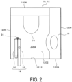
- a body 12 of the aircraft lavatory unit 10 includes: a floor plate 1202; a front wall 1204 and a rear wall 1206 standing upright from the floor plate 1202 and facing each other; a pair of side walls 1208 standing upright from the floor plate 1202 and connecting both sides of the front wall 1204 and the rear wall 1206; and a ceiling 1210, a toilet 14 is provided at a section on the floor plate 1202 near the rear wall 1206, a sink 16 is provided on one side wall 1208 of the pair of side walls 1208, and the inside of the body 12 is a lavatory 1002.
- An entrance 1212 of the lavatory 1002 is provided in the front wall 1204.
- a door member for entrance opening and closing 18 that opens and closes the entrance 1212 is formed by two door members, a first door member 20 and a second door member 22 that are foldably joined to each other.
- the first door member 20 and the second door member 22 are foldably joined by a joining structure 24, where the entrance 1212 is closed, with the first door member 20 and the second door member 22 being in an extended state, or in other words, in a state in which these door members 20, 22 extend along the same straight line when viewed in a plan view, and the entrance 1212 is open, with the first door member 20 and the second door member 22 being in a folded state in a convex shape toward the lavatory 1002 side.
- a shaft 2002 is provided so as to be movable up and down on upper and lower end surfaces of an end portion of the first door member 20 located opposite to the second door member 22, the shaft 2002 is inserted into a hole of a mounting frame (not illustrated) provided in the entrance 1212, and in the entrance 1212, the first door member 20 is arranged swingably around the shaft 2002.
- a sliding member 2202 is provided on upper and lower end surfaces of an end portion of the second door member 22 located opposite to the first door member 20, this sliding member 2202 is engaged with a guide rail of the mounting frame (not illustrated) provided at the entrance 1212, and the sliding member 2202 moves along the guide rail when the entrance 1212 is opened and closed.
- a reference sign 2004 denotes an indicator portion configured to indicate that the first door member 20 is to be pressed by hand
- a reference sign 2006 denotes a rubber base that cushions the impact when the first door member 20 and the second door member 22 are folded
- a reference sign 2204 denotes a lamp that indicates that the lavatory 1002 is in use.
- a damper (not illustrated) is provided that slows down the movement of the first door member 20 and the second door member 22 when transitioning from a folded state to an extended state and suppresses the impact noise when closing the entrance 1212.
- the joining structure 24 of the two door members 20, 22 that form the door member for entrance opening and closing 18 is configured to include a pair of brackets 26, a bracket joining shaft 28, a pair of covers 30, a cover joining shaft 32, bracket cover joining shafts 34, and torsion springs 36.
- the pair of brackets 26 includes: a first bracket 26A attached to an end portion of the first door member 20 on the second door member 22 side; and a second bracket 26B attached to an end portion of the second door member 22 on the first door member 20 side, and the first bracket 26A and the second bracket 26B are joined swingably by the bracket joining shaft 28.
- the pair of covers 30 includes: a first cover 30A and a second cover 30B, where one end of the first cover 30A is joined to the first bracket 26A swingably by a bracket cover joining shaft 34A, and one end of the second cover 30B is joined to the second bracket 26B swingably by the bracket cover joining shaft 34B.
- the other end of the first cover 30A and the other end of the second cover 30B are joined swingably by the cover joining shaft 32.
- the first bracket 26A and the second bracket 26B satisfy the requirements for durability and appearance of the joining structure 24, so they are formed of a lightweight metal material with strength and rigidity such as an aluminum alloy or the like, and the first cover 30A and the second cover 30B do not receive the load of the door member for entrance opening and closing 18, so they are formed of a lightweight metal material such as an aluminum alloy or the like; or a synthetic resin.
- the bracket joining shaft 28, the cover joining shaft 32, and the bracket cover joining shafts 34A, 34B are made of a steel rod material such as piano wire or the like.
- the first bracket 26A has: a mounting plate portion 38 attached to an end portion of the first door member 20; and a hinge portion 40 protruding from the mounting plate portion 38.
- the mounting plate portion 38 has: a base portion 3802 that comes into contact with an end surface of the end portion of the first door member 20; and a pair of flanges 3804 that stand up from both sides of the base portion 3802 and that are fitted to a side surface of the first door member 20, where the base portion 3802 and the pair of flanges 3804 have a length extending over the entire length in a vertical direction of the end portion of the first door member 20.
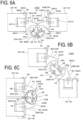
- Mounting holes 3806 are formed at a plurality of sections at intervals in the vertical direction from the mounting plate portion 38, and as illustrated in FIG. 6A , screws N1 inserted into the mounting holes 3806 are screwed into female screw members 2010 embedded in the end portion of the first door member 20 to attach the first bracket 26A to the end portion of the first door member 20.
- the first bracket 26A may be attached to the first door member 20 by using an adhesive instead of the screws N1.
- the hinge portion 40 has an upright portion 4002 that stands up from the mounting plate portion 38 at a substantially right angle and, as illustrated in FIG. 6A , has a bent portion 4004 that extends in a direction away from the lavatory 1002 from a tip portion of the upright portion 4002, with the entrance 1212 being in a closed state, and the upright portion 4002 and the bent portion 4004 have a length extending over the entire length in the vertical direction of the end portion of the first door member 20.
- a first shaft receiving portion 42 that supports the bracket joining shaft 28 is provided at a tip portion of the bent portion 4004, and a second shaft receiving portion 44 that supports the bracket cover joining shaft 34A is provided at a section on the base portion 3802 side of the bent portion 4004.
- the first shaft receiving portion 42 is configured to include: a shaft receiving hole 4202 that supports the bracket joining shaft 28; and a cutout portion 4204 that allows the bracket joining shaft 28 to be inserted into and removed from the shaft receiving hole 4202.
- a plurality of the first shaft receiving portions 42 are provided at intervals in an extending direction of the first bracket 26A, and between the first shaft receiving portions 42 are cutout portions 43 where first shaft receiving portions 42 are not provided, with a section above the uppermost first shaft receiving portion 42 also being the cutout portion 43 where the first shaft receiving portion 42 is not provided.
- the second shaft receiving portion 44 is configured to include: a shaft receiving hole 4402 that supports the bracket cover joining shaft 34A; and a cutout portion 4404 that allows the bracket cover joining shaft 34A to be inserted into and removed from the shaft receiving hole 4402.
- a cutout portion 46 into which a sixth shaft receiving portion 74 of the first cover 30A is inserted, which will be described later, is formed on the mounting plate portion 38 side in an open state, at a section where the second shaft receiving portion 44 faces the mounting plate portion 38.
- the second bracket 26B has: a mounting plate portion 48 attached to an end portion of the second door member 22; and a hinge portion 50 protruding from the mounting plate portion 48.
- the mounting plate portion 48 has: a base portion 4802 that comes into contact with an end surface of the end portion of the second door member 22; and a pair of flanges 4804 that stand up from both sides of the base portion 4802 and that are fitted to a side surface of the second door member 22, where the base portion 4802 and the pair of flanges 4804 have a length extending over the entire length in the vertical direction of the end portion of the second door member 22.
- Mounting holes 4806 are formed at a plurality of sections at intervals in the vertical direction from the mounting plate portion 48, and as illustrated in FIG. 6A , screws N2 inserted through the mounting hole 4806 are screwed into female screw members 2210 embedded in the end portion of the second door member 22 to attach the second bracket 26B to the end portion of the second door member 22. Note that the second bracket 26B may be attached to the second door member 22 by using an adhesive instead of the screws N2.
- the hinge portion 50 has an upright portion 5002 that stands up from the mounting plate portion 48 at a substantially right angle and has a bent portion 5004 that extends in a direction away from the lavatory 1002 from a tip portion of the upright portion 5002, with the entrance 1212 being in a closed state; and the upright portion 5002 and the bent portion 5004 have a length extending over the entire length in the vertical direction of the end portion of the first door member 20.
- a third shaft receiving portion 54 that supports the bracket joining shaft 28 is provided at a tip portion of the bent portion 5004, and a fourth shaft receiving portion 56 that supports the bracket cover joining shaft 34 is provided at a section on the base portion 4802 side of the bent portion 5004.
- the third shaft receiving portion 54 is configured to include: a shaft receiving hole 5402 that supports the bracket joining shaft 28; and a cutout portion 5404 that allows the bracket joining shaft 28 to be inserted into and removed from the shaft receiving hole 5402.
- a plurality of the third shaft receiving portions 54 are provided at intervals in the extending direction of the second bracket 26B, and between the third shaft receiving portions 54 are cutout portions 52 where the third shaft receiving portions 54 are not provided.
- the fourth shaft receiving portion 56 is configured to include: a shaft receiving hole 5602 that supports the bracket cover joining shaft 34B; and a cutout portion 5604 that allows the bracket cover joining shaft 34B to be inserted into and removed from the shaft receiving hole 5602.
- a cutout portion 58 into which an eighth shaft receiving portion 82 of the second cover 30B is inserted, which will be described later, is formed on the mounting plate portion 48 side in an open state, at a section where the fourth shaft receiving portion 56 faces the mounting plate portion 48.
- the uppermost third shaft receiving portion 54 of the second bracket 26B is located at an upper end of the second bracket 26B, a lower end surface 5410 of the third shaft receiving portion 54 is fitted with an upper end surface 4210 of the first shaft receiving portion 42 located at the highest position of the first bracket 26A, so in this way the third shaft receiving portion 54 and the first shaft receiving portion 42 are alternately arranged in the vertical direction, and the first bracket 26A and the second bracket 26B are joined swingably by the bracket joining shaft 28 inserted through the shaft receiving hole 5402 from the cutout portions 5404, 4204 of the third shaft receiving portions 54 and the first shaft receiving portions 42.
- bracket joining shaft 28 is joined to one of the shaft receiving holes 5402 or 4202 of the third shaft receiving portions 54 and the first shaft receiving portions 42 so as not to be movable in the vertical direction and not rotatable and is joined to the other shaft receiving holes 5402 or 4202 of the third shaft receiving portions 54 and the first shaft receiving portions 42 so as to be rotatable; or such that the bracket joining shaft 28 is joined in a manner that a large-diameter portion larger than the shaft receiving holes 5402, 4202 provided at the upper end of the bracket joining shaft 28 is locked to the upper end surface of the third shaft receiving portion 54 located at the uppermost position, so the bracket joining shaft 28 is able to rotate in the shaft receiving holes 5402 of both the third shaft receiving portions 54 and the first shaft receiving portions 42.
- the end surfaces of the third shaft receiving portions 54 come in contact with the end surfaces of the first shaft receiving portions 42 that are opposed to each other in the vertical direction, except for a section where the torsion springs 36 are disposed.
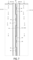
- the third shaft receiving portions 54 of the second bracket 26B and the first shaft receiving portions 42 of the first bracket 26A are vertically arranged in this way; however, as illustrated in FIG. 7 , at the plurality of sections where these shaft receiving portions 54, 42 are arranged, spaces 60 extending in the vertical direction are maintained between the lower end surfaces of the first shaft receiving portions 42 and the upper end surfaces of the third shaft receiving portions 54, via the cutout portions 43, 52, and the torsion spring 36 is disposed in the spaces 60.
- the torsion springs 36 apply a bias force to the first door member 20 and the second door member 22 in an extended state.
- each torsion spring 36 has a coil portion 3602 and rod-like portions 3604 protruding from both ends of the coil portion 3602.
- the coil portion 3602 is disposed between the lower end surface of a first shaft receiving portion 42 and the upper end surface of a third shaft receiving portion 54, and the bracket joining shaft 28 is inserted through the inner portion of the coil portion 3602.
- one rod-like portion 3604 is abutted against a recess portion 64 of the first bracket 26A by a tip portion 6204 of a pressing piece 62, and a base portion 6202 of the pressing piece 62 is attached to the upright portion 4002 by screws N3.
- the recess portion 64 is formed so as to extend from a section of the bent portion 4004 between the upper and lower first shaft receiving portions 42 toward a section of a rear surface of the second shaft receiving portion 44, and a groove 6402 that can be locked to the rod-like portion 3604 is formed in the central portion of a bottom surface of the recess portion 64 so that the rod-like portion 3604 may be easily pressed.
- the other rod-like portion 3604 is abutted against a recess portion 66 of the second bracket 26B by the tip portion 6204 of the pressing piece 62, and the base portion 6202 of the pressing piece 62 is attached to the upright portion 5002 by screws N4.
- the recess portion 66 is formed so as to extend from a section of the bent portion 5004 between the upper and lower third shaft receiving portions 54 toward a section of a rear surface of the fourth shaft receiving portion 44, and a groove 6602 that can be locked to the rod-like portion 3604 is formed in the central portion of a bottom surface of the recess portion 66 so that the rod-like portion 3604 may be easily pressed.
- the first cover 30A includes: a main body plate portion 68 having an arc-shaped outer circumferential surface 6802; a fifth shaft receiving portion 70 that is provided at one end in an arc direction of an inner circumferential surface 6804 of the main body plate portion 68 and that supports the cover joining shaft 32; a leg portion 72 protruding from the other end in the arc direction of the inner circumferential surface 6804 of the main body plate portion 68; and the sixth shaft receiving portion 74 that is provided at a tip end of the leg portion 72 and that supports the bracket cover joining shaft 34A.
- the main body plate portion 68 has a length extending over the entire length in the vertical direction of the end portions of the first and second door members 20, 22, and the outer circumferential surface 6802 of the main body plate portion 68 is formed as a cylindrical surface.
- the fifth shaft receiving portion 70 is configured to include: a shaft receiving hole 7002 that supports the cover joining shaft 32; and cutout portions 7004 that allow the cover joining shaft 32 to be inserted in or removed from the shaft receiving hole 7002, with a plurality of the fifth shaft receiving portions 70 being provided at intervals in the extending direction of the main body plate portion 68, and as illustrated in FIG. 4 , the length in the arc direction of the main body plate portion 68 in a section where the fifth shaft receiving portion 70 is provided is larger than the length of the main body plate portion 68 in a section where the fifth shaft receiving portion 70 is not provided.
- the cover joining shaft 32 is disposed at a section farther away from the lavatory 1002 than the bracket joining shaft 28, with the first door member 20 and the second door member 22 being in an extended state.
- the sixth shaft receiving portion 74 is configured to include: a shaft receiving hole 7402 that supports the bracket cover joining shaft 34A; and a cutout portion 7404 that allows the bracket cover joining shaft 34A to be inserted into and removed from the shaft receiving hole 7402, and a plurality of the sixth shaft receiving portions 74 are provided at intervals in the extending direction of the main body plate portion 68 having a size so as to be insertable into the cutout portions 46 of the first bracket 26A.
- the second cover 30B includes: a main body plate portion 76 having an arc-shaped outer circumferential surface 7602; a seventh shaft receiving portion 78 that is provided at one end in the arc direction of an inner circumferential surface 7604 of the main body plate portion 76 and that supports the cover joining shaft 32; a leg portion 80 protruding from the other end in the arc direction of the inner circumferential surface 7604 of the main body plate portion 76; and the eighth shaft receiving portion 82 that is provided at a tip end of the leg portion 80 and that supports the bracket cover joining shaft 34B.
- the main body plate portion 76 has a length extending over the entire length in the vertical direction of the end portions of the first and second door members 20, 22, and the outer circumferential surface 7602 of the main body plate portion 76 is formed as a cylindrical surface having an identical diameter as the outer circumferential surface 6802 of the first cover 30A.
- the seventh shaft receiving portion 78 is configured to include: a shaft receiving hole 7802 that supports the cover joining shaft 32; and a cutout portion 7804 that allows the cover joining shaft 32 to be inserted into or removed from the shaft receiving hole 7802, a plurality of the seventh shaft receiving portions 78 are provided at intervals in the extending direction of the main body plate portion 76, and as illustrated in FIG. 4 , the length in the arc direction of the main body plate portion 76 in a section where the seventh shaft receiving portion 78 is provided is larger than the length of the main body plate portion 76 in a section where the seventh shaft receiving portion 78 is not provided.
- the eighth shaft receiving portion 82 is configured to include: a shaft receiving hole 8202 that supports the bracket cover joining shaft 34B; and a cutout portion 8204 that allows the bracket cover joining shaft 34B to be inserted into and removed from the shaft receiving hole 8202, and a plurality of the eighth shaft receiving portions 82 are provided at intervals in the extending direction of the main body plate portion 76 having a size so as to be insertable into the cutout portions 58 of the second bracket 26B.
- the seventh shaft receiving portion 78 located at the uppermost position of the second cover 30B is located at an upper end of the second cover 30B, and an upper end surface 7010 of the fifth shaft receiving portion 70 located at the uppermost position of the first cover 30A is fitted to a lower end surface 7810 of the seventh shaft receiving portion 78, in this way, the seventh shaft receiving portion 78 and the fifth shaft receiving portion 70 are alternately arranged in the vertical direction, and the first cover 30A and the second cover 30B are joined swingably by the cover joining shaft 32 inserted through the shaft receiving holes 7802, 7002 from cutout portions 7804, 7004 of the seventh shaft receiving portions 78 and the fifth shaft receiving portions 70.
- the sixth shaft receiving portions 74 of the first cover 30A are inserted into the cutout portions 46 of the first bracket 26A, and the sixth shaft receiving portions 74 of the first cover 30A and the second shaft receiving portions 44 of the first bracket 26A are joined swingably by the bracket cover joining shaft 34A that is inserted through the shaft receiving holes 7402 of the sixth shaft receiving portions 74 and the shaft receiving holes 4402 of the second shaft receiving portions 44 of the first bracket 26A.
- the eight shaft receiving portions 82 of the second cover 30B are inserted into the cutout portions 58 of the second bracket 26B, and the eighth shaft receiving portions 82 of the second cover 30B and the fourth shaft receiving portions 56 of the second bracket 26B are joined swingably by the bracket cover joining shaft 34B that is inserted through the shaft receiving holes 8202 of the eighth shaft receiving portions 82 and the shaft receiving holes 5602 of the fourth shaft receiving portions 56 of the second bracket 26B.
- the vertical length of the main body plate portion 76 where the uppermost seventh shaft receiving portion 78 of the second cover 30B is located is short, arranged below, the vertical lengths of: the main body plate portion 68 where the fifth shaft receiving portion 70 of the first cover 30A is located; and the main body plate portion 76 where the seventh shaft receiving portion 78 of the second cover 30B is located are large, and the vertical length of the main body plate portion 68 where the lowermost fifth shaft receiving portion 70 of the first cover 30A is located is also short.
- an end portion 7602A in the arc direction of the outer circumferential surface 7602 of the main body plate portion 76 where the seventh shaft receiving portion 78 of the second cover 30B is located is substantially in contact with an end portion 68A in the arc direction of the main body plate portion 68 where the fifth shaft receiving portion 70 of the first cover 30A is not provided, similarly, as illustrated in FIG.
- an end portion 6802A in the arc direction of the outer circumferential surface 6802 of the main body plate portion 68 where the fifth shaft receiving portion 70 of the first cover 30A is located is substantially in contact with an end portion 76A in the arc direction of the main body plate portion 76 where the seventh shaft receiving portion 78 of the second cover 30B is not provided, and further, facing each other in the vertical direction, the end surface of the seventh shaft receiving portion 78 of the second cover 30B and the end surface of the fifth shaft receiving portion 70 of the first cover 30A are substantially in contact with each other.
- a cylindrical surface that is in a convex shape and continuous in the vertical direction without gaps is formed on the outside of the lavatory 1002, by the outer circumferential surface 6802 of the main body plate portion 68 of the first cover 30A and the outer circumferential surface 7602 of the main body plate portion 76 of the second cover 30B, which is more advantageous in improving the appearance.
- the pair of covers 30 is housed in a space S between the mounting plate portions 38, 48 of the pair of brackets 26, the upright portions 4002, 5002, and the bent portions 4004, 5004, and thus folding of the first door member 20 and the second door member 22 may be performed smoothly.
- the pair of brackets 26 provided on the pair of door members 20, 22 are joined swingably by the bracket joining shaft 28, and furthermore, together with one ends of the pair of covers 30 being joined swingably to the cover joining shaft 32, the other ends of the pair of covers 30 are joined to the respective pair of brackets 26 swingably by the bracket cover joining shafts 34A, 34B.
- all of the joining sections have a pivotal structure, so compared with a conventional case in which a cover made of a flexible material such as rubber is interposed between the end portions of two doors for deformation, this structure is advantageous in that the two door members may be smoothly folded and extended without the occurrence of resistance, the opening and closing operability of the door member for entrance opening and closing 18 is improved, and the durability performance of the door member for entrance opening and closing 18 is improved.
- the pair of covers 30 covers a section of the pair of brackets 26 around the bracket joining shaft 28 over the entire length in the vertical direction from the outside of lavatory, so this is advantageous in effectively preventing light leakage from the lavatory 1002 during use and is advantageous in improving the appearance.
- the bracket 26 has: the mounting plate portions 38, 48 that are attached to the opposite end portions of the door members 20, 22; the upright portions 4002, 5002 standing upright from the mounting plate portions 38, 48; and the bent portions 4004, 5004 extending from the tip portions of the upright portions 4002. 5002 in directions away from the lavatory 1002.
- first to fourth shaft receiving portions 42, 44, 54, 56 are provided at the tip portions of the bent portions 4004, 5004, with the entrance 1212 being in a closed state by the door member for entrance opening and closing 18, only the mounting plate portions 38, 48 of the pair of brackets 26 and the upright portions 4002, 5002 may be seen from the inside of the lavatory 1002, and most of the first to fourth shaft receiving portions 42, 44, 54, 56 are hidden by the upright portions 4002, 5002 of the pair of brackets 26, so this is advantageous in improving the appearance from the inside of the lavatory 1002.
Landscapes
- Engineering & Computer Science (AREA)
- Mechanical Engineering (AREA)
- Aviation & Aerospace Engineering (AREA)
- Civil Engineering (AREA)
- Structural Engineering (AREA)
- Extensible Doors And Revolving Doors (AREA)
- Wing Frames And Configurations (AREA)
- Support Devices For Sliding Doors (AREA)
- Closing And Opening Devices For Wings, And Checks For Wings (AREA)
Description
- The present invention relates to a joining structure of two door members that form a door for entrance opening and closing of an aircraft lavatory unit.
- The door for entrance opening and closing of an aircraft lavatory unit has a first door member and a second door member that are foldably joined to each other, and these two door members are configured to close the entrance in an extended state and configured to open the entrance in a folded state in a convex shape toward the lavatory side.
The door for entrance opening and closing is required by each airline company to have a predetermined durability performance and also required to have no light leakage when the lavatory is used and to have a good appearance.
In the related art, such as inUS 2016/083092 A1 , in order to prevent light leakage when using a lavatory, it has been proposed to provide a cover made of a flexible material such as rubber or the like between the end portions of two doors facing each other. Further solutions, known fromJP H08 13933 A US 9 297 190 B2 US 2011/214355 A1 andJP 2013-224525 A -
- Patent Document 1:
JP H08 13933 A - Patent Document 2:
US 9 297 190 B2 - Patent Document 3:
US 2011/214355 A1 - Patent Document 4:
US 2016/083092 A1 - Patent Document 5:
JP 2013-224525 A - However, the cover is folded and deformed when opening and closing the entrance, so the cover becomes a resistance when the two door members are folded, and there is room for improvement in terms of opening and closing operability of the door for entrance opening and closing, and there is also room for improvement in terms of appearance. The present invention has been devised in view of the above circumstances, and an object of the present invention is to provide a joining structure of two door members that form a door for entrance opening and closing of an aircraft lavatory unit having excellent opening and closing operability and able to meet the requirements of durability performance, light leakage, and appearance.
- In order to achieve the object described above, the present invention is a joining structure of two door members forming a door for entrance opening and closing of an aircraft lavatory unit including:
- a door member for entrance opening and closing for opening and closing an entrance of a lavatory of an aircraft lavatory unit;
- the door member for entrance opening and closing including a first door member and a second door member that are foldably joined to each other,
- the two door members being configured to close the entrance in an extended state and being configured to open the entrance in a folded state in a convex shape toward a side of the lavatory;
- the joining structure including:
- a pair of brackets respectively protruding from opposite end portions of the first door member and the second door member;
- a bracket joining shaft that joins tip portions of the pair of brackets swingably; and
- a pair of covers, one end of each being joined to a section of the pair of brackets around the bracket joining shaft swingably by a bracket cover joining shaft, an other end of each being joined swingably by a cover joining shaft, at a section farther away from the lavatory than the bracket joining shaft;
- the pair of covers, with the first door member and the second door member being in an extended state, covering sections of the pair of brackets around the bracket joining shaft over the entire length in a vertical direction from the outside of the lavatory.
- mounting plate portions attached to opposite end portions of the first door member and the second door member in an extended state;
- upright portions standing upright from the mounting plate portions; and bent portions extending from tip portions of the upright portions in directions away from the lavatory;
- shaft receiving portions that support the bracket joining shaft are provided at tip portions of the bent portions; and
- shaft receiving portions that support the bracket cover joining shaft are provided at sections of the tip portions the bent portions that face the mounting plate portions, at sections nearer to the mounting plate portions than the shaft receiving portions.
- In addition, in the present invention, the pair of covers, with the first door member and the second door member being in a folded state, is housed in a space between the mounting plate portions, the upright portions, and the bent portions of the pair of brackets.
- Furthermore, in the present invention,
- a plurality of shaft receiving portions that support the bracket joining shaft of the pair of brackets are provided at intervals in a vertical direction of the mounting plate portion;
- the plurality of shaft receiving portions of the pair of brackets are arranged alternately in the vertical direction; and
- a torsion spring for applying a bias force to the first door member and the second door member in an extended state; wherein
- the torsion spring includes a coil portion and a pair of rod-like portions protruding from both ends of the coil portion; and
- in the torsion spring, the coil portion is disposed between shaft receiving portions of the pair of brackets, the bracket joining shaft is inserted through an inside of the coil portion, and one of the pair of rod-like portions is abutted against one bracket of the pair of brackets, and an other of the pair of rod-like portions is abutted against an other bracket of the pair of brackets.
- Moreover, in the present invention, the pair of covers includes:
- a main body plate portion, an outer circumferential surface of which is arc shaped and extends in the vertical direction;
- a shaft receiving portion that is provided at one end in an arc direction of an inner circumferential surface of the main body plate portion and supports the cover joining shaft; and
- a shaft receiving portion that is provided on an other end in the arc direction of the inner circumferential surface of the main body plate portion and supports the bracket cover joining shaft;
- a plurality of the shaft receiving portions that support the cover joining shaft are provided at intervals in an extending direction of the main body plate portion;
- a length in the arc direction of a section of the main body plate portion where the shaft receiving portion that supports the cover joining shaft is provided is larger, compared to a section of the main body plate portion where the shaft receiving portion is not provided;
- a shaft receiving portion, supporting the cover joining shaft, of one cover of the pair of covers and a shaft receiving portion, supporting the cover joining shaft, of an other cover of the pair of covers are alternately arranged in the vertical direction;
- an end portion in the arc direction of the main body plate portion provided with a shaft receiving portion, supporting the cover joining shaft, of one cover of the pair of covers comes in contact with an end portion in the arc direction of the main body plate portion where the shaft receiving portion, supporting the cover joining shaft, of an other cover of the pair of covers is not provided;
- an end portion in the arc direction of the main body plate portion provided with a shaft receiving portion, supporting the cover joining shaft, of an other cover of the pair of covers comes in contact with an end portion in the arc direction of the main body plate portion where the shaft receiving portion, supporting the cover joining shaft, of one cover of the pair of covers is not provided;
- facing each other in the vertical direction, an end surface of a shaft receiving portion, supporting the cover joining shaft, of one cover of the pair of covers comes in contact with an end surface of a shaft receiving portion, supporting the cover joining shaft, of an other cover of the pair of covers; and
- with the first door member and the second door member being in an extended state, the outer circumferential surfaces of the main body plate portions of the pair of covers are cylindrical surfaces continuous in the vertical direction.
- According to the present invention, joining sections of a pair of brackets and joining sections of a pair of covers all have a pivotal structure, so two door members may be smoothly folded and extended without the occurrence of resistance, which is advantageous in improving the opening and closing operability of a door for entrance opening and closing and improving the durability performance of the door for entrance opening and closing.
- In addition, with an entrance being in a closed state by the door for entrance opening and closing, the pair of covers covers a section of the pair of brackets around a bracket joining shaft over the entire length in a vertical direction from the outside of a lavatory, so this is advantageous in effectively preventing light leakage from the lavatory during use and is also advantageous in improving appearance.
- Moreover, with the entrance being in a closed state by the door for entrance opening and closing, only mounting plate portions and upright portions of the pair of brackets may be seen from the inside of the lavatory, and most of the sections where the pair of brackets are joined by the bracket joining shaft are hidden by the upright portions of the pair of brackets, so this is advantageous in improving the appearance from the inside of the lavatory. Furthermore, with the entrance being in an opened state by folding a pair of door members, the pair of covers is housed in the space between the mounting plate portions, the upright portions, and bent portions of the pair of brackets, so this is advantageous in that the pair of door members may be folded smoothly.
- In addition, a torsion spring for applying a bias force to the pair of door members in an extended state may be arranged at a location hidden by the pair of covers, which is advantageous in improving the appearance of the door for entrance opening and closing.
- Moreover, with the entrance being in a closed state by the door for entrance opening and closing, outer circumferential surfaces of main body plate portions of the pair of covers are cylindrical surfaces continuous in the vertical direction, so this is even more advantageous in improving the appearance of the door for entrance opening and closing.
-
- FIG. 1
- is a front view of an aircraft lavatory unit, with an entrance of a lavatory being in a closed state.
- FIG. 2
- is a plan view of an aircraft lavatory unit, with the entrance of the lavatory being in an opened state.
- FIG. 3
- is a front view of a door for entrance opening and closing, with a first door member and a second door member being in an extended state.
- FIG. 4
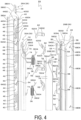
- is a perspective view of each component viewed from the outside of the lavatory, with each component constituting a joining structure of the first door member and the second door member removed from a door member.
- FIG. 5
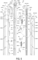
- is a perspective view of each component viewed from the inside of the lavatory with each component constituting the joining structure of the first door member and the second door member removed from the door member.
- FIGS.
- 6A to 6C are plan views illustrating an extended state and a bent state of the joining structure of the first door member and the second door member.
- FIG. 7
- is a front view, as seen from the outside of the lavatory, of an upper portion of the joining structure of the first door member and the second door member in an extended state where the cover is removed.
- FIG. 8
- is a cross-sectional view taken along A-A in
FIG. 7 . - FIG. 9
- is a cross-sectional view taken along B-B in
FIG. 7 . - FIG. 10
- is a cross-sectional view taken along C-C in
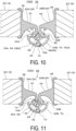
FIG. 7 . - FIG. 11
- is a cross-sectional view taken along D-D in
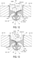
FIG. 7 . - FIG. 12
- is a cross-sectional view taken along E-E in
FIG. 7 . - FIG. 13
- is a cross-sectional view taken along F-F in
FIG. 7 . - Hereinafter, embodiments of the present invention will be described. As illustrated in
FIGS. 1 and2 , a body 12 of the aircraft lavatory unit 10 includes: afloor plate 1202; afront wall 1204 and arear wall 1206 standing upright from thefloor plate 1202 and facing each other; a pair ofside walls 1208 standing upright from thefloor plate 1202 and connecting both sides of thefront wall 1204 and therear wall 1206; and aceiling 1210, atoilet 14 is provided at a section on thefloor plate 1202 near therear wall 1206, asink 16 is provided on oneside wall 1208 of the pair ofside walls 1208, and the inside of the body 12 is alavatory 1002. Anentrance 1212 of thelavatory 1002 is provided in thefront wall 1204. A door member for entrance opening and closing 18 that opens and closes theentrance 1212 is formed by two door members, afirst door member 20 and asecond door member 22 that are foldably joined to each other. Thefirst door member 20 and thesecond door member 22 are foldably joined by a joiningstructure 24, where theentrance 1212 is closed, with thefirst door member 20 and thesecond door member 22 being in an extended state, or in other words, in a state in which thesedoor members entrance 1212 is open, with thefirst door member 20 and thesecond door member 22 being in a folded state in a convex shape toward thelavatory 1002 side. - As illustrated in
FIG. 3 , ashaft 2002 is provided so as to be movable up and down on upper and lower end surfaces of an end portion of thefirst door member 20 located opposite to thesecond door member 22, theshaft 2002 is inserted into a hole of a mounting frame (not illustrated) provided in theentrance 1212, and in theentrance 1212, thefirst door member 20 is arranged swingably around theshaft 2002. - Moreover, a sliding
member 2202 is provided on upper and lower end surfaces of an end portion of thesecond door member 22 located opposite to thefirst door member 20, this slidingmember 2202 is engaged with a guide rail of the mounting frame (not illustrated) provided at theentrance 1212, and the slidingmember 2202 moves along the guide rail when theentrance 1212 is opened and closed. - Note that in
FIG. 3 , areference sign 2004 denotes an indicator portion configured to indicate that thefirst door member 20 is to be pressed by hand, areference sign 2006 denotes a rubber base that cushions the impact when thefirst door member 20 and thesecond door member 22 are folded, and areference sign 2204 denotes a lamp that indicates that thelavatory 1002 is in use. - In addition, a damper (not illustrated) is provided that slows down the movement of the
first door member 20 and thesecond door member 22 when transitioning from a folded state to an extended state and suppresses the impact noise when closing theentrance 1212. - As illustrated in
FIGS. 4 ,5 , and6 , the joiningstructure 24 of the twodoor members brackets 26, abracket joining shaft 28, a pair ofcovers 30, acover joining shaft 32, bracket cover joining shafts 34, and torsion springs 36. - The pair of
brackets 26 includes: afirst bracket 26A attached to an end portion of thefirst door member 20 on thesecond door member 22 side; and asecond bracket 26B attached to an end portion of thesecond door member 22 on thefirst door member 20 side, and thefirst bracket 26A and thesecond bracket 26B are joined swingably by thebracket joining shaft 28. - The pair of
covers 30 includes: afirst cover 30A and asecond cover 30B, where one end of thefirst cover 30A is joined to thefirst bracket 26A swingably by a bracketcover joining shaft 34A, and one end of thesecond cover 30B is joined to thesecond bracket 26B swingably by the bracketcover joining shaft 34B. - The other end of the
first cover 30A and the other end of thesecond cover 30B are joined swingably by thecover joining shaft 32. - The
first bracket 26A and thesecond bracket 26B satisfy the requirements for durability and appearance of the joiningstructure 24, so they are formed of a lightweight metal material with strength and rigidity such as an aluminum alloy or the like, and thefirst cover 30A and thesecond cover 30B do not receive the load of the door member for entrance opening and closing 18, so they are formed of a lightweight metal material such as an aluminum alloy or the like; or a synthetic resin. - From the perspective of durability, the
bracket joining shaft 28, thecover joining shaft 32, and the bracketcover joining shafts - As illustrated in
FIGS. 4 and5 , thefirst bracket 26A has: a mountingplate portion 38 attached to an end portion of thefirst door member 20; and ahinge portion 40 protruding from the mountingplate portion 38. - The mounting
plate portion 38 has: abase portion 3802 that comes into contact with an end surface of the end portion of thefirst door member 20; and a pair offlanges 3804 that stand up from both sides of thebase portion 3802 and that are fitted to a side surface of thefirst door member 20, where thebase portion 3802 and the pair offlanges 3804 have a length extending over the entire length in a vertical direction of the end portion of thefirst door member 20. - Mounting
holes 3806 are formed at a plurality of sections at intervals in the vertical direction from the mountingplate portion 38, and as illustrated inFIG. 6A , screws N1 inserted into the mountingholes 3806 are screwed intofemale screw members 2010 embedded in the end portion of thefirst door member 20 to attach thefirst bracket 26A to the end portion of thefirst door member 20. Note that thefirst bracket 26A may be attached to thefirst door member 20 by using an adhesive instead of the screws N1. - The
hinge portion 40 has anupright portion 4002 that stands up from the mountingplate portion 38 at a substantially right angle and, as illustrated inFIG. 6A , has abent portion 4004 that extends in a direction away from thelavatory 1002 from a tip portion of theupright portion 4002, with theentrance 1212 being in a closed state, and theupright portion 4002 and thebent portion 4004 have a length extending over the entire length in the vertical direction of the end portion of thefirst door member 20. - A first
shaft receiving portion 42 that supports thebracket joining shaft 28 is provided at a tip portion of thebent portion 4004, and a secondshaft receiving portion 44 that supports the bracketcover joining shaft 34A is provided at a section on thebase portion 3802 side of thebent portion 4004. - As illustrated in
FIG. 4 , the firstshaft receiving portion 42 is configured to include: ashaft receiving hole 4202 that supports thebracket joining shaft 28; and acutout portion 4204 that allows thebracket joining shaft 28 to be inserted into and removed from theshaft receiving hole 4202. - A plurality of the first
shaft receiving portions 42 are provided at intervals in an extending direction of thefirst bracket 26A, and between the firstshaft receiving portions 42 arecutout portions 43 where firstshaft receiving portions 42 are not provided, with a section above the uppermost firstshaft receiving portion 42 also being thecutout portion 43 where the firstshaft receiving portion 42 is not provided. - As illustrated in
FIGS. 4 and5 , the secondshaft receiving portion 44 is configured to include: ashaft receiving hole 4402 that supports the bracketcover joining shaft 34A; and acutout portion 4404 that allows the bracketcover joining shaft 34A to be inserted into and removed from theshaft receiving hole 4402. - Moreover, as illustrated in
FIGS. 4 and11 , at each section of the secondshaft receiving section 44 provided with the firstshaft receiving portion 42, acutout portion 46, into which a sixthshaft receiving portion 74 of thefirst cover 30A is inserted, which will be described later, is formed on the mountingplate portion 38 side in an open state, at a section where the secondshaft receiving portion 44 faces the mountingplate portion 38. - As illustrated in
FIGS. 4 and5 , thesecond bracket 26B has: a mountingplate portion 48 attached to an end portion of thesecond door member 22; and ahinge portion 50 protruding from the mountingplate portion 48. - The mounting
plate portion 48 has: abase portion 4802 that comes into contact with an end surface of the end portion of thesecond door member 22; and a pair offlanges 4804 that stand up from both sides of thebase portion 4802 and that are fitted to a side surface of thesecond door member 22, where thebase portion 4802 and the pair offlanges 4804 have a length extending over the entire length in the vertical direction of the end portion of thesecond door member 22. - Mounting
holes 4806 are formed at a plurality of sections at intervals in the vertical direction from the mountingplate portion 48, and as illustrated inFIG. 6A , screws N2 inserted through the mountinghole 4806 are screwed intofemale screw members 2210 embedded in the end portion of thesecond door member 22 to attach thesecond bracket 26B to the end portion of thesecond door member 22. Note that thesecond bracket 26B may be attached to thesecond door member 22 by using an adhesive instead of the screws N2. - The
hinge portion 50 has anupright portion 5002 that stands up from the mountingplate portion 48 at a substantially right angle and has abent portion 5004 that extends in a direction away from thelavatory 1002 from a tip portion of theupright portion 5002, with theentrance 1212 being in a closed state; and theupright portion 5002 and thebent portion 5004 have a length extending over the entire length in the vertical direction of the end portion of thefirst door member 20. - A third
shaft receiving portion 54 that supports thebracket joining shaft 28 is provided at a tip portion of thebent portion 5004, and a fourthshaft receiving portion 56 that supports the bracket cover joining shaft 34 is provided at a section on thebase portion 4802 side of thebent portion 5004. - The third
shaft receiving portion 54 is configured to include: ashaft receiving hole 5402 that supports thebracket joining shaft 28; and acutout portion 5404 that allows thebracket joining shaft 28 to be inserted into and removed from theshaft receiving hole 5402. - A plurality of the third
shaft receiving portions 54 are provided at intervals in the extending direction of thesecond bracket 26B, and between the thirdshaft receiving portions 54 arecutout portions 52 where the thirdshaft receiving portions 54 are not provided. - The fourth
shaft receiving portion 56 is configured to include: ashaft receiving hole 5602 that supports the bracketcover joining shaft 34B; and acutout portion 5604 that allows the bracketcover joining shaft 34B to be inserted into and removed from theshaft receiving hole 5602. - In addition, as illustrated in
FIGS. 4 and9 , at each section of a fourthshaft receiving portion 56 provided with a thirdshaft receiving portion 54, acutout portion 58, into which an eighthshaft receiving portion 82 of thesecond cover 30B is inserted, which will be described later, is formed on the mountingplate portion 48 side in an open state, at a section where the fourthshaft receiving portion 56 faces the mountingplate portion 48. - As illustrated in
FIGS. 4 and5 , the uppermost thirdshaft receiving portion 54 of thesecond bracket 26B is located at an upper end of thesecond bracket 26B, alower end surface 5410 of the thirdshaft receiving portion 54 is fitted with anupper end surface 4210 of the firstshaft receiving portion 42 located at the highest position of thefirst bracket 26A, so in this way the thirdshaft receiving portion 54 and the firstshaft receiving portion 42 are alternately arranged in the vertical direction, and thefirst bracket 26A and thesecond bracket 26B are joined swingably by thebracket joining shaft 28 inserted through theshaft receiving hole 5402 from thecutout portions shaft receiving portions 54 and the firstshaft receiving portions 42. - Note that conventionally known configurations, in which shaft receiving holes of two members are joined to one support shaft, may also be employed, such that the
bracket joining shaft 28 is joined to one of theshaft receiving holes shaft receiving portions 54 and the firstshaft receiving portions 42 so as not to be movable in the vertical direction and not rotatable and is joined to the othershaft receiving holes shaft receiving portions 54 and the firstshaft receiving portions 42 so as to be rotatable; or such that thebracket joining shaft 28 is joined in a manner that a large-diameter portion larger than theshaft receiving holes bracket joining shaft 28 is locked to the upper end surface of the thirdshaft receiving portion 54 located at the uppermost position, so thebracket joining shaft 28 is able to rotate in theshaft receiving holes 5402 of both the thirdshaft receiving portions 54 and the firstshaft receiving portions 42. - In addition, the end surfaces of the third
shaft receiving portions 54 come in contact with the end surfaces of the firstshaft receiving portions 42 that are opposed to each other in the vertical direction, except for a section where the torsion springs 36 are disposed. - The third
shaft receiving portions 54 of thesecond bracket 26B and the firstshaft receiving portions 42 of thefirst bracket 26A are vertically arranged in this way; however, as illustrated inFIG. 7 , at the plurality of sections where theseshaft receiving portions spaces 60 extending in the vertical direction are maintained between the lower end surfaces of the firstshaft receiving portions 42 and the upper end surfaces of the thirdshaft receiving portions 54, via thecutout portions torsion spring 36 is disposed in thespaces 60. - The torsion springs 36 apply a bias force to the
first door member 20 and thesecond door member 22 in an extended state. - As illustrated in
FIGS. 4 and5 , eachtorsion spring 36 has acoil portion 3602 and rod-like portions 3604 protruding from both ends of thecoil portion 3602. - As illustrated in
FIGS. 7 ,12, and 13 , in thetorsion spring 36, thecoil portion 3602 is disposed between the lower end surface of a firstshaft receiving portion 42 and the upper end surface of a thirdshaft receiving portion 54, and thebracket joining shaft 28 is inserted through the inner portion of thecoil portion 3602. - As illustrated in
FIG. 13 , one rod-like portion 3604 is abutted against arecess portion 64 of thefirst bracket 26A by atip portion 6204 of apressing piece 62, and abase portion 6202 of thepressing piece 62 is attached to theupright portion 4002 by screws N3. As illustrated inFIG. 4 , therecess portion 64 is formed so as to extend from a section of thebent portion 4004 between the upper and lower firstshaft receiving portions 42 toward a section of a rear surface of the secondshaft receiving portion 44, and agroove 6402 that can be locked to the rod-like portion 3604 is formed in the central portion of a bottom surface of therecess portion 64 so that the rod-like portion 3604 may be easily pressed. - As illustrated in
FIG. 12 , the other rod-like portion 3604 is abutted against arecess portion 66 of thesecond bracket 26B by thetip portion 6204 of thepressing piece 62, and thebase portion 6202 of thepressing piece 62 is attached to theupright portion 5002 by screws N4. As illustrated inFIG. 5 , therecess portion 66 is formed so as to extend from a section of thebent portion 5004 between the upper and lower thirdshaft receiving portions 54 toward a section of a rear surface of the fourthshaft receiving portion 44, and agroove 6602 that can be locked to the rod-like portion 3604 is formed in the central portion of a bottom surface of therecess portion 66 so that the rod-like portion 3604 may be easily pressed. - As illustrated in
FIGS. 4 and5 , thefirst cover 30A includes: a mainbody plate portion 68 having an arc-shaped outercircumferential surface 6802; a fifthshaft receiving portion 70 that is provided at one end in an arc direction of an innercircumferential surface 6804 of the mainbody plate portion 68 and that supports thecover joining shaft 32; aleg portion 72 protruding from the other end in the arc direction of the innercircumferential surface 6804 of the mainbody plate portion 68; and the sixthshaft receiving portion 74 that is provided at a tip end of theleg portion 72 and that supports the bracketcover joining shaft 34A. - The main
body plate portion 68 has a length extending over the entire length in the vertical direction of the end portions of the first andsecond door members circumferential surface 6802 of the mainbody plate portion 68 is formed as a cylindrical surface. - The fifth
shaft receiving portion 70 is configured to include: ashaft receiving hole 7002 that supports thecover joining shaft 32; andcutout portions 7004 that allow thecover joining shaft 32 to be inserted in or removed from theshaft receiving hole 7002, with a plurality of the fifthshaft receiving portions 70 being provided at intervals in the extending direction of the mainbody plate portion 68, and as illustrated inFIG. 4 , the length in the arc direction of the mainbody plate portion 68 in a section where the fifthshaft receiving portion 70 is provided is larger than the length of the mainbody plate portion 68 in a section where the fifthshaft receiving portion 70 is not provided. - Note that as illustrated in
FIG. 8 , thecover joining shaft 32 is disposed at a section farther away from thelavatory 1002 than thebracket joining shaft 28, with thefirst door member 20 and thesecond door member 22 being in an extended state. - As illustrated in
FIGS. 5 and11 , the sixthshaft receiving portion 74 is configured to include: ashaft receiving hole 7402 that supports the bracketcover joining shaft 34A; and acutout portion 7404 that allows the bracketcover joining shaft 34A to be inserted into and removed from theshaft receiving hole 7402, and a plurality of the sixthshaft receiving portions 74 are provided at intervals in the extending direction of the mainbody plate portion 68 having a size so as to be insertable into thecutout portions 46 of thefirst bracket 26A. - As illustrated in
FIGS. 4 and5 , thesecond cover 30B includes: a mainbody plate portion 76 having an arc-shaped outercircumferential surface 7602; a seventhshaft receiving portion 78 that is provided at one end in the arc direction of an innercircumferential surface 7604 of the mainbody plate portion 76 and that supports thecover joining shaft 32; aleg portion 80 protruding from the other end in the arc direction of the innercircumferential surface 7604 of the mainbody plate portion 76; and the eighthshaft receiving portion 82 that is provided at a tip end of theleg portion 80 and that supports the bracketcover joining shaft 34B. The mainbody plate portion 76 has a length extending over the entire length in the vertical direction of the end portions of the first andsecond door members circumferential surface 7602 of the mainbody plate portion 76 is formed as a cylindrical surface having an identical diameter as the outercircumferential surface 6802 of thefirst cover 30A. - The seventh
shaft receiving portion 78 is configured to include: ashaft receiving hole 7802 that supports thecover joining shaft 32; and acutout portion 7804 that allows thecover joining shaft 32 to be inserted into or removed from theshaft receiving hole 7802, a plurality of the seventhshaft receiving portions 78 are provided at intervals in the extending direction of the mainbody plate portion 76, and as illustrated inFIG. 4 , the length in the arc direction of the mainbody plate portion 76 in a section where the seventhshaft receiving portion 78 is provided is larger than the length of the mainbody plate portion 76 in a section where the seventhshaft receiving portion 78 is not provided. - As illustrated in
FIGS. 5 and9 , the eighthshaft receiving portion 82 is configured to include: ashaft receiving hole 8202 that supports the bracketcover joining shaft 34B; and acutout portion 8204 that allows the bracketcover joining shaft 34B to be inserted into and removed from theshaft receiving hole 8202, and a plurality of the eighthshaft receiving portions 82 are provided at intervals in the extending direction of the mainbody plate portion 76 having a size so as to be insertable into thecutout portions 58 of thesecond bracket 26B. - As illustrated in
FIGS. 4 and5 , the seventhshaft receiving portion 78 located at the uppermost position of thesecond cover 30B is located at an upper end of thesecond cover 30B, and anupper end surface 7010 of the fifthshaft receiving portion 70 located at the uppermost position of thefirst cover 30A is fitted to alower end surface 7810 of the seventhshaft receiving portion 78, in this way, the seventhshaft receiving portion 78 and the fifthshaft receiving portion 70 are alternately arranged in the vertical direction, and thefirst cover 30A and thesecond cover 30B are joined swingably by thecover joining shaft 32 inserted through theshaft receiving holes cutout portions shaft receiving portions 78 and the fifthshaft receiving portions 70. - Note that conventionally known configurations, in which shaft receiving holes of two members are joined to one support shaft, may also be employed, such that the
cover joining shaft 32 is joined to one of theshaft receiving holes shaft receiving portion 78 and the fifthshaft receiving portions 70 so as not to be movable in the vertical direction and not rotatable and is joined to the othershaft receiving holes shaft receiving portions 78 and the fifthshaft receiving portions 70 so as to rotatable; or such that thecover joining shaft 32 is joined in a manner that a large-diameter portion larger than theshaft receiving holes cover joining shaft 32 is locked to the upper end surface of the seventhshaft receiving portion 78 located at the uppermost position, so thecover joining shaft 32 is able to rotate in theshaft receiving holes shaft receiving portions 78 and the fifthshaft receiving portions 70. - As illustrated in
FIGS. 4 ,5 , and11 , the sixthshaft receiving portions 74 of thefirst cover 30A are inserted into thecutout portions 46 of thefirst bracket 26A, and the sixthshaft receiving portions 74 of thefirst cover 30A and the secondshaft receiving portions 44 of thefirst bracket 26A are joined swingably by the bracketcover joining shaft 34A that is inserted through theshaft receiving holes 7402 of the sixthshaft receiving portions 74 and theshaft receiving holes 4402 of the secondshaft receiving portions 44 of thefirst bracket 26A. - As illustrated in
FIGS. 4 ,5 , and9 , the eightshaft receiving portions 82 of thesecond cover 30B are inserted into thecutout portions 58 of thesecond bracket 26B, and the eighthshaft receiving portions 82 of thesecond cover 30B and the fourthshaft receiving portions 56 of thesecond bracket 26B are joined swingably by the bracketcover joining shaft 34B that is inserted through theshaft receiving holes 8202 of the eighthshaft receiving portions 82 and theshaft receiving holes 5602 of the fourthshaft receiving portions 56 of thesecond bracket 26B. - Note that various conventionally known configurations may be adopted such that, similar to as described above, the shaft receiving holes of the two members are joined to one support shaft, for the case of joining of the bracket
cover joining shaft 34A with respect to the sixthshaft receiving portions 74 of thefirst cover 30A and the secondshaft receiving portions 44 of thefirst bracket 26A; and for the case of joining of the bracketcover joining shaft 34B with respect to the eighthshaft receiving portions 82 of thesecond cover 30B and the fourthshaft receiving portions 56 of thesecond bracket 26B. - In this way, with the
entrance 1212 being in a closed state in which the pair ofcovers 30 is joined to the pair ofbrackets 26 and in which thefirst door member 20 and thesecond door member 22 are extended, as illustrated inFIGS. 3 and6A , due to the pair ofcovers 30, the section of the pair ofbrackets 26 around thebracket joining shaft 28, or in other words, thebent portions brackets 26, is hidden by thebody plate portions covers 30 over the entire length in the vertical direction. - Note that, as illustrated in
FIG. 3 , the vertical length of the mainbody plate portion 76 where the uppermost seventhshaft receiving portion 78 of thesecond cover 30B is located is short, arranged below, the vertical lengths of: the mainbody plate portion 68 where the fifthshaft receiving portion 70 of thefirst cover 30A is located; and the mainbody plate portion 76 where the seventhshaft receiving portion 78 of thesecond cover 30B is located are large, and the vertical length of the mainbody plate portion 68 where the lowermost fifthshaft receiving portion 70 of thefirst cover 30A is located is also short. - Moreover, as illustrated in
FIG. 9 , anend portion 7602A in the arc direction of the outercircumferential surface 7602 of the mainbody plate portion 76 where the seventhshaft receiving portion 78 of thesecond cover 30B is located is substantially in contact with anend portion 68A in the arc direction of the mainbody plate portion 68 where the fifthshaft receiving portion 70 of thefirst cover 30A is not provided, similarly, as illustrated inFIG. 10 , anend portion 6802A in the arc direction of the outercircumferential surface 6802 of the mainbody plate portion 68 where the fifthshaft receiving portion 70 of thefirst cover 30A is located is substantially in contact with anend portion 76A in the arc direction of the mainbody plate portion 76 where the seventhshaft receiving portion 78 of thesecond cover 30B is not provided, and further, facing each other in the vertical direction, the end surface of the seventhshaft receiving portion 78 of thesecond cover 30B and the end surface of the fifthshaft receiving portion 70 of thefirst cover 30A are substantially in contact with each other. - Therefore, with the
entrance 1212 being in a closed state in which thefirst door member 20 and thesecond door member 22 are extended, a cylindrical surface that is in a convex shape and continuous in the vertical direction without gaps is formed on the outside of thelavatory 1002, by the outercircumferential surface 6802 of the mainbody plate portion 68 of thefirst cover 30A and the outercircumferential surface 7602 of the mainbody plate portion 76 of thesecond cover 30B, which is more advantageous in improving the appearance. - Moreover, with the
entrance 1212 being in a state in which thefirst door member 20 and thesecond door member 22 are folded, as illustrated inFIG. 6C , the pair ofcovers 30 is housed in a space S between the mountingplate portions brackets 26, theupright portions bent portions first door member 20 and thesecond door member 22 may be performed smoothly. - With the joining
structure 24 of two door members that form the door member for entrance opening and closing 18 of an aircraft lavatory unit 10 of the present embodiment, the pair ofbrackets 26 provided on the pair ofdoor members bracket joining shaft 28, and furthermore, together with one ends of the pair ofcovers 30 being joined swingably to thecover joining shaft 32, the other ends of the pair ofcovers 30 are joined to the respective pair ofbrackets 26 swingably by the bracketcover joining shafts - Moreover, with the
entrance 1212 being in a closed state by the door member for entrance opening and closing 18, the pair ofcovers 30 covers a section of the pair ofbrackets 26 around thebracket joining shaft 28 over the entire length in the vertical direction from the outside of lavatory, so this is advantageous in effectively preventing light leakage from thelavatory 1002 during use and is advantageous in improving the appearance. Moreover, with the pair ofdoor members bracket 26 has: the mountingplate portions door members upright portions plate portions bent portions upright portions 4002. 5002 in directions away from thelavatory 1002. Since the first to fourthshaft receiving portions bent portions entrance 1212 being in a closed state by the door member for entrance opening and closing 18, only the mountingplate portions brackets 26 and theupright portions lavatory 1002, and most of the first to fourthshaft receiving portions upright portions brackets 26, so this is advantageous in improving the appearance from the inside of thelavatory 1002. -
- 10 Aircraft lavatory unit
- 1002 Lavatory
- 1212 Entrance
- 18 Door member for entrance opening and closing
- 20 First door member
- 22 Second door member
- 24 Joining structure
- 26 Pair of brackets
- 26A First Bracket
- 26B Second Bracket
- 28 Bracket joining shaft
- 30 Pair of covers
- 30A First cover
- 30B Second cover
- 32 Cover joining shaft
- 34A, 34B Bracket cover joining shaft
- 36 Torsion spring
- 3602 Coil portion
- 3604 Rod-like portion
- 38 Mounting plate portion
- 4002 Upright portion
- 4004 Bent portion
- 42 First shaft receiving portion
- 44 Second shaft receiving portion
- 5002 Upright portion
- 5004 Bent portion
- 54 Third shaft receiving portion
- 56 Fourth shaft receiving portion
- 68 Main body plate portion
- 70 Fifth shaft receiving portion
- 74 Sixth shaft receiving portion
- 76 Main body plate portion
- 78 Seventh shaft receiving portion
- 82 Eighth shaft receiving portion
- S Space
Claims (5)
- A joining structure (24) for joining two door members (20, 22) forming a door for entrance opening and closing of an aircraft lavatory unit (10), said door comprising:a door member for entrance opening and closing (18) for opening and closing an entrance (1212) of a lavatory (1002) of an aircraft lavatory unit (10);the door member for entrance opening and closing (18) comprising a first door member (20) and a second door member (22) that are foldably joined to each other, the two door members (20, 22) being configured to close the entrance (1212) in an extended state and being configured to open the entrance (1212) in a folded state in a convex shape toward a side of the lavatory (1002),the joining structure (24) comprising:
a pair of brackets (26) being protrudingly mountable from opposite end portions of the first door member (20) and the second door member (22); anda bracket joining shaft (28) that joins tip portions of the pair of brackets (26) swingably;the joining structure (24) being characterized in that it further comprises
a pair of covers (30), one end of each being joined to a section of the pair of brackets (26) around the bracket joining shaft (28) swingably by a bracket cover joining shaft (34A, 34B), an other end of each being joined swingably by a cover joining shaft (32), PHwhich, when the joining structure (24) is mounted to the door members (20, 22), is at a section farther away from the lavatory (1002) than the bracket joining shaft (28);the pair of covers (30) with the first door member (20) and the second door member (22) being in an extended state, covering sections of the pair of brackets (26) around the bracket joining shaft (28) over the entire length in a vertical direction from an outside of the lavatory (1002). - The joining structure (24) according to claim 1, wherein
the pair of brackets (26) comprises:mounting plate portions (38) attached to opposite end portions of the first door member (20) and the second door member (22) in an extended state;upright portions (4002, 5002) standing upright from the mounting plate portions (38); andbent portions (4004, 5004) extending from tip portions of the upright portions (4002, 5002) in directions away from the lavatory (1002);shaft receiving portions (42, 54) that support the bracket joining shaft (28) are provided at tip portions of the bent portions (4004, 5004); andshaft receiving portions (44, 74, 56, 82) that support the bracket cover joining shaft (34a, 34b) are provided at sections of the tip portions the bent portions (4004, 5004) that face the mounting plate portions (38, 48), at sections nearer to the mounting plate portions (38, 48) than the shaft receiving portions (44, 74, 56, 82). - The joining structure (24) according to claim 1, wherein
the pair of covers (30), with the first door member (20) and the second door member (22) being in a folded state, is housed in a space between the mounting plate portions (38, 48), the upright portions (4002, 5002), and the bent portions (4004, 5004) of the pair of brackets (26). - The joining structure (24) according to claim 2 or 3 further comprising:a plurality of shaft receiving portions (42, 54) that support the bracket joining shaft (28) of the pair of brackets (26) are provided at intervals in a vertical direction of the mounting plate portion (38, 48); the plurality of shaft receiving portions (42, 54) of the pair of brackets (26) are arranged alternately in the vertical direction; anda torsion spring (36) for applying a bias force to the first door member (20) and the second door member (22) in an extended state; whereinthe torsion spring (36) comprises a coil portion (3602) and a pair of rod-like portions (3604) protruding from both ends of the coil portion (3602); andin the torsion spring (36), the coil portion (3602) is disposed between shaft receiving portions (42, 54) of the pair of brackets (26), the bracket joining shaft (28) is inserted through an inside of the coil portion (3602), and one of the pair of rod-like portions (3604) is abutted against one bracket (26A) of the pair of brackets (26), and an other of the pair of rod-like portions (3604) is abutted against an other bracket (26B) of the pair of brackets (26).
- The joining structure (24) according to any one of claims 2 to 4, wherein the pair of covers (30) comprises:a main body plate portion (68, 76), an outer circumferential surface (6802, 7602) of which is arc shaped and extends in the vertical direction;a shaft receiving portion (70, 78) that is provided at one end in an arc direction of an inner circumferential surface of the main body plate portion (68, 76) and supports the cover joining shaft (32); anda shaft receiving portion (74, 82) that is provided on an other end in the arc direction of the inner circumferential surface of the main body plate portion (68, 76) and supports the bracket cover joining shaft (34A, 34B);a plurality of the shaft receiving portions (70, 78) that support the cover joining shaft (32) are provided at intervals in an extending direction of the main body plate portion (68, 76);a length in the arc direction of a section of the main body plate portion (68, 76) where the shaft receiving portion (70, 78) that supports the cover joining shaft (32) is provided is larger, compared to a section of the main body plate portion (68, 76) where the shaft receiving portion (70, 78) is not provided;a shaft receiving portion (70), supporting the cover joining shaft (32), of one cover (30A) of the pair of covers (30) and a shaft receiving portion (78), supporting the cover joining shaft (32), of an other cover (30B) of the pair of covers (30) are alternately arranged in the vertical direction;an end portion (7602A) in the arc direction of the main body plate portion (76) provided with a shaft receiving portion (78), supporting the cover joining shaft (32), of one cover (30B) of the pair of covers comes (30) in contact with an end portion (68A) in the arc direction of the main body plate portion (68) where the shaft receiving portion (70), supporting the cover joining shaft (32), of an other cover (30A) of the pair of covers (30) is not provided;an end portion 6802A in the arc direction of the main body plate portion (68) provided with a shaft receiving portion (70), supporting the cover joining shaft (32), of an other cover (30A) of the pair of covers (30) comes in contact with an end portion (76A) in the arc direction of the main body plate portion (76) where the shaft receiving portion (78), supporting the cover joining shaft (32), of one cover (30B) of the pair of covers (30) is not provided;facing each other in the vertical direction, an end surface of a shaft receiving portion (78), supporting the cover joining shaft (32), of one cover (30B) of the pair of covers (30) comes in contact with an end surface of a shaft receiving portion (70), supporting the cover joining shaft (32), of an other cover (30A) of the pair of covers (30); andwith the first door member (20) and the second door member (22) being in an extended state, the outer circumferential surfaces (6802) of the main body plate portions (68) of the pair of covers (30) are cylindrical surfaces continuous in the vertical direction.
Applications Claiming Priority (2)
| Application Number | Priority Date | Filing Date | Title |
|---|---|---|---|
| JP2018077481A JP6544460B1 (en) | 2018-04-13 | 2018-04-13 | Joint structure of two doors constituting the door for opening and closing the entrance and exit of the aircraft restroom unit |
| PCT/JP2019/015817 WO2019198798A1 (en) | 2018-04-13 | 2019-04-11 | Joining structure for two door-bodies forming door for opening and closing exit/entrance of aircraft lavatory unit |
Publications (3)
| Publication Number | Publication Date |
|---|---|
| EP3779110A1 EP3779110A1 (en) | 2021-02-17 |
| EP3779110A4 EP3779110A4 (en) | 2022-01-05 |
| EP3779110B1 true EP3779110B1 (en) | 2024-01-24 |
Family
ID=67297529
Family Applications (1)
| Application Number | Title | Priority Date | Filing Date |
|---|---|---|---|
| EP19785638.8A Active EP3779110B1 (en) | 2018-04-13 | 2019-04-11 | Joining structure for two door-bodies forming door for opening and closing exit/entrance of aircraft lavatory unit |
Country Status (4)
| Country | Link |
|---|---|
| US (1) | US11047158B2 (en) |
| EP (1) | EP3779110B1 (en) |
| JP (1) | JP6544460B1 (en) |
| WO (1) | WO2019198798A1 (en) |
Families Citing this family (11)
| Publication number | Priority date | Publication date | Assignee | Title |
|---|---|---|---|---|
| AT519908B1 (en) * | 2017-05-11 | 2020-07-15 | Blum Gmbh Julius | Furniture and arrangement for use in furniture |
| AT521814B1 (en) * | 2018-11-13 | 2023-04-15 | Blum Gmbh Julius | furniture hinge |
| USD936459S1 (en) * | 2019-10-14 | 2021-11-23 | Dirtt Environmental Solutions Ltd. | Door and ceiling frame component |
| USD974149S1 (en) * | 2019-10-16 | 2023-01-03 | Dirtt Environmental Solutions Ltd. | Ceiling hanger |
| GB202002074D0 (en) * | 2020-02-14 | 2020-04-01 | Kingsway Enterprises Uk Ltd | Hinge |
| CA3111699A1 (en) * | 2020-03-10 | 2021-09-10 | Eckel Industries Of Canada Limited | Door hinge |
| US11542736B2 (en) * | 2020-12-21 | 2023-01-03 | B/E Aerospace, Inc. | Piano hinges |
| US12227941B2 (en) * | 2021-07-11 | 2025-02-18 | Kadeya Enterprise Co. , Ltd | Folding dividing screen structure |
| US11920391B2 (en) * | 2021-09-10 | 2024-03-05 | Dee Zee, Inc. | Hinge covers for exposed vehicle door hinges |
| JP7230999B1 (en) | 2021-12-02 | 2023-03-01 | 横浜ゴム株式会社 | Airplane lavatory unit door opening/closing mechanism |
| JP7231000B1 (en) | 2021-12-02 | 2023-03-01 | 横浜ゴム株式会社 | Airplane lavatory unit door opening/closing mechanism |
Family Cites Families (26)
| Publication number | Priority date | Publication date | Assignee | Title |
|---|---|---|---|---|
| US2910741A (en) * | 1956-11-02 | 1959-11-03 | George W Houlsby Jr | Safety device for swinging doors |
| US3949801A (en) * | 1974-11-29 | 1976-04-13 | Giichi Sasaki | Device for automatically closing a folding door |
| FR2523199B1 (en) * | 1982-03-15 | 1986-07-11 | Jouve Guy | ARTICULATED PROTECTION PLATE, ADAPTABLE TO DOOR OPENING |
| JPH0349271Y2 (en) * | 1984-12-10 | 1991-10-21 | ||
| US5001862A (en) * | 1987-12-18 | 1991-03-26 | Abraham Albenda | Safety attachment for hinged side of doors |
| JPH0430691A (en) | 1990-05-24 | 1992-02-03 | Matsushita Electric Ind Co Ltd | Color signal processing unit |
| JPH0430691U (en) * | 1990-07-09 | 1992-03-12 | ||
| US5224240A (en) * | 1991-07-15 | 1993-07-06 | Smith David C | Hinge masking device and method |
| JPH0813933A (en) * | 1994-06-28 | 1996-01-16 | Ota Seisakusho:Kk | Folding door gap cover device |
| US6276026B1 (en) * | 1997-03-10 | 2001-08-21 | The Boeing Company | Aircraft hinge |
| DE50001870D1 (en) * | 1999-03-02 | 2003-05-28 | Phoenix Ag | Gap covering |
| US6434888B1 (en) * | 2001-03-26 | 2002-08-20 | William Shaw | Door gap finger guard |
| US20030205001A1 (en) * | 2002-05-03 | 2003-11-06 | Williams Wendy Christman | Fastened door gap cover and technique for covering the gap between open door and door frame on hinge side of door |
| GB0217580D0 (en) * | 2002-07-30 | 2002-09-11 | Webb Stephen R | Door safety device |
| US6877695B2 (en) * | 2002-12-13 | 2005-04-12 | The Boeing Company | Hinge cover integration into door seal edges |
| DE102004034903A1 (en) * | 2004-07-19 | 2006-02-16 | Airbus Deutschland Gmbh | Covering device for door hinge of aircraft, includes flexible covering set across gap between two hinge pieces of door hinge and which can adjust between stretched and unstretched conditions based on size of gap between hinge pieces |
| US7520022B2 (en) * | 2005-04-07 | 2009-04-21 | Bobrick Washroom Equipment, Inc. | Spring and hinge assembly for installing a door on toilet partitions |
| US20090151264A1 (en) * | 2007-12-18 | 2009-06-18 | Safety Door International, Llc | Safety door assembly and method for child door safety |
| US20100088962A1 (en) * | 2008-10-13 | 2010-04-15 | Integrated Capital Properties, Llc | Door safety shield |
| US7861465B1 (en) * | 2009-09-21 | 2011-01-04 | Joseph Christ | Flexible door guard |
| KR101084286B1 (en) * | 2010-03-05 | 2011-11-17 | 에스 김 제임스 | Door gap protector |
| JP5949084B2 (en) | 2012-04-20 | 2016-07-06 | 横浜ゴム株式会社 | Door opening and closing device |
| GB2505720B (en) * | 2012-09-11 | 2018-08-01 | Finger Clear Ltd | Protective cover device including expansion panels for covering the angle formed between the edge of a hinged door and a door frame |
| CN104420751B (en) * | 2013-08-20 | 2016-12-28 | 李祯祥 | Hinge devices for folding doors |
| EP3122979B1 (en) | 2014-03-27 | 2019-05-15 | C&D Zodiac, Inc. | Bi-fold door module |
| US9181749B1 (en) * | 2015-03-05 | 2015-11-10 | Raymond E Davis | Deformable hinge gap blocker for the protection of hands and fingers |
-
2018
- 2018-04-13 JP JP2018077481A patent/JP6544460B1/en active Active
-
2019
- 2019-04-11 US US17/047,378 patent/US11047158B2/en active Active
- 2019-04-11 WO PCT/JP2019/015817 patent/WO2019198798A1/en not_active Ceased
- 2019-04-11 EP EP19785638.8A patent/EP3779110B1/en active Active
Also Published As
| Publication number | Publication date |
|---|---|
| WO2019198798A1 (en) | 2019-10-17 |
| US20210115716A1 (en) | 2021-04-22 |
| US11047158B2 (en) | 2021-06-29 |
| EP3779110A1 (en) | 2021-02-17 |
| JP6544460B1 (en) | 2019-07-17 |
| EP3779110A4 (en) | 2022-01-05 |
| JP2019183537A (en) | 2019-10-24 |
Similar Documents
| Publication | Publication Date | Title |
|---|---|---|
| EP3779110B1 (en) | Joining structure for two door-bodies forming door for opening and closing exit/entrance of aircraft lavatory unit | |
| AU2010285684B2 (en) | Door opening/closing system and catch therefor | |
| JP7401783B2 (en) | Connection structure of lavatory door body of aircraft lavatory unit | |
| US20140310915A1 (en) | Holding hinge assembly | |
| JP2013511455A (en) | Elevator car emergency escape door | |
| US20110271485A1 (en) | Control motion hinge with torsion spring | |
| US20170198511A1 (en) | Multi-directional rotational sliding door self-closing device | |
| CN115126364A (en) | Concealed external hinge rotating at 180 degrees | |
| US8393056B2 (en) | Control motion hinge | |
| JP6034088B2 (en) | Anti-finger structure in door body | |
| JP4277932B2 (en) | Door structure | |
| JP2005299253A (en) | Invisible hinge | |
| JP6838914B2 (en) | door | |
| EP2453089B1 (en) | Door wing sliding supporting device | |
| US20240337141A1 (en) | Fitting for movably mounting a pivoting element | |
| AU2019207655C1 (en) | Furniture hinge, furniture panel, and furniture body | |
| KR102582609B1 (en) | Functionality Folding Door | |
| JP7221820B2 (en) | door | |
| JP2589363Y2 (en) | Hinge | |
| JP6662598B2 (en) | Joinery | |
| KR101651746B1 (en) | Apparatus for pretecting deflection of midddle frame in windows and doors | |
| JP7548758B2 (en) | Arc-shaped door device | |
| JP7117003B2 (en) | Bottom door stopper for top hanging type sliding door | |
| JP6489456B2 (en) | Lower end holding tool and door device provided with the same | |
| RU2278936C2 (en) | Door hinge |
Legal Events
| Date | Code | Title | Description |
|---|---|---|---|
| STAA | Information on the status of an ep patent application or granted ep patent |
Free format text: STATUS: THE INTERNATIONAL PUBLICATION HAS BEEN MADE |
|
| PUAI | Public reference made under article 153(3) epc to a published international application that has entered the european phase |
Free format text: ORIGINAL CODE: 0009012 |
|
| STAA | Information on the status of an ep patent application or granted ep patent |
Free format text: STATUS: REQUEST FOR EXAMINATION WAS MADE |
|
| 17P | Request for examination filed |
Effective date: 20201007 |
|
| AK | Designated contracting states |
Kind code of ref document: A1 Designated state(s): AL AT BE BG CH CY CZ DE DK EE ES FI FR GB GR HR HU IE IS IT LI LT LU LV MC MK MT NL NO PL PT RO RS SE SI SK SM TR |
|
| AX | Request for extension of the european patent |
Extension state: BA ME |
|
| DAV | Request for validation of the european patent (deleted) | ||
| DAX | Request for extension of the european patent (deleted) | ||
| A4 | Supplementary search report drawn up and despatched |
Effective date: 20211203 |
|
| RIC1 | Information provided on ipc code assigned before grant |
Ipc: E05D 7/00 20060101ALI20211129BHEP Ipc: E05D 11/00 20060101ALI20211129BHEP Ipc: E06B 3/48 20060101ALI20211129BHEP Ipc: E05F 1/12 20060101ALI20211129BHEP Ipc: B64D 11/02 20060101ALI20211129BHEP Ipc: E05D 15/26 20060101AFI20211129BHEP |
|
| RIC1 | Information provided on ipc code assigned before grant |
Ipc: E05D 7/00 20060101ALI20230314BHEP Ipc: E05D 11/00 20060101ALI20230314BHEP Ipc: E06B 3/48 20060101ALI20230314BHEP Ipc: E05F 1/12 20060101ALI20230314BHEP Ipc: B64D 11/02 20060101ALI20230314BHEP Ipc: E05D 15/26 20060101AFI20230314BHEP |
|
| GRAP | Despatch of communication of intention to grant a patent |
Free format text: ORIGINAL CODE: EPIDOSNIGR1 |
|
| STAA | Information on the status of an ep patent application or granted ep patent |
Free format text: STATUS: GRANT OF PATENT IS INTENDED |
|
| INTG | Intention to grant announced |
Effective date: 20230504 |
|
| GRAJ | Information related to disapproval of communication of intention to grant by the applicant or resumption of examination proceedings by the epo deleted |
Free format text: ORIGINAL CODE: EPIDOSDIGR1 |
|
| STAA | Information on the status of an ep patent application or granted ep patent |
Free format text: STATUS: REQUEST FOR EXAMINATION WAS MADE |
|
| INTC | Intention to grant announced (deleted) | ||
| GRAP | Despatch of communication of intention to grant a patent |
Free format text: ORIGINAL CODE: EPIDOSNIGR1 |
|
| STAA | Information on the status of an ep patent application or granted ep patent |
Free format text: STATUS: GRANT OF PATENT IS INTENDED |
|
| INTG | Intention to grant announced |
Effective date: 20230926 |
|
| RAP3 | Party data changed (applicant data changed or rights of an application transferred) |
Owner name: THE YOKOHAMA RUBBER CO., LTD. |
|
| GRAS | Grant fee paid |
Free format text: ORIGINAL CODE: EPIDOSNIGR3 |
|
| GRAA | (expected) grant |
Free format text: ORIGINAL CODE: 0009210 |
|
| STAA | Information on the status of an ep patent application or granted ep patent |
Free format text: STATUS: THE PATENT HAS BEEN GRANTED |
|
| AK | Designated contracting states |
Kind code of ref document: B1 Designated state(s): AL AT BE BG CH CY CZ DE DK EE ES FI FR GB GR HR HU IE IS IT LI LT LU LV MC MK MT NL NO PL PT RO RS SE SI SK SM TR |
|
| REG | Reference to a national code |
Ref country code: GB Ref legal event code: FG4D |
|
| REG | Reference to a national code |
Ref country code: CH Ref legal event code: EP |
|
| REG | Reference to a national code |
Ref country code: DE Ref legal event code: R096 Ref document number: 602019045651 Country of ref document: DE |
|
| REG | Reference to a national code |
Ref country code: IE Ref legal event code: FG4D |
|
| P01 | Opt-out of the competence of the unified patent court (upc) registered |
Effective date: 20240221 |
|
| REG | Reference to a national code |
Ref country code: LT Ref legal event code: MG9D |
|
| REG | Reference to a national code |
Ref country code: NL Ref legal event code: MP Effective date: 20240124 |
|
| PG25 | Lapsed in a contracting state [announced via postgrant information from national office to epo] |
Ref country code: NL Free format text: LAPSE BECAUSE OF FAILURE TO SUBMIT A TRANSLATION OF THE DESCRIPTION OR TO PAY THE FEE WITHIN THE PRESCRIBED TIME-LIMIT Effective date: 20240124 |
|
| PG25 | Lapsed in a contracting state [announced via postgrant information from national office to epo] |
Ref country code: NL Free format text: LAPSE BECAUSE OF FAILURE TO SUBMIT A TRANSLATION OF THE DESCRIPTION OR TO PAY THE FEE WITHIN THE PRESCRIBED TIME-LIMIT Effective date: 20240124 |
|
| PG25 | Lapsed in a contracting state [announced via postgrant information from national office to epo] |
Ref country code: IS Free format text: LAPSE BECAUSE OF FAILURE TO SUBMIT A TRANSLATION OF THE DESCRIPTION OR TO PAY THE FEE WITHIN THE PRESCRIBED TIME-LIMIT Effective date: 20240524 |
|
| PG25 | Lapsed in a contracting state [announced via postgrant information from national office to epo] |
Ref country code: LT Free format text: LAPSE BECAUSE OF FAILURE TO SUBMIT A TRANSLATION OF THE DESCRIPTION OR TO PAY THE FEE WITHIN THE PRESCRIBED TIME-LIMIT Effective date: 20240124 |
|
| PG25 | Lapsed in a contracting state [announced via postgrant information from national office to epo] |
Ref country code: GR Free format text: LAPSE BECAUSE OF FAILURE TO SUBMIT A TRANSLATION OF THE DESCRIPTION OR TO PAY THE FEE WITHIN THE PRESCRIBED TIME-LIMIT Effective date: 20240425 |
|
| REG | Reference to a national code |
Ref country code: AT Ref legal event code: MK05 Ref document number: 1652333 Country of ref document: AT Kind code of ref document: T Effective date: 20240124 |
|
| PG25 | Lapsed in a contracting state [announced via postgrant information from national office to epo] |
Ref country code: HR Free format text: LAPSE BECAUSE OF FAILURE TO SUBMIT A TRANSLATION OF THE DESCRIPTION OR TO PAY THE FEE WITHIN THE PRESCRIBED TIME-LIMIT Effective date: 20240124 Ref country code: RS Free format text: LAPSE BECAUSE OF FAILURE TO SUBMIT A TRANSLATION OF THE DESCRIPTION OR TO PAY THE FEE WITHIN THE PRESCRIBED TIME-LIMIT Effective date: 20240424 |
|
| PG25 | Lapsed in a contracting state [announced via postgrant information from national office to epo] |
Ref country code: ES Free format text: LAPSE BECAUSE OF FAILURE TO SUBMIT A TRANSLATION OF THE DESCRIPTION OR TO PAY THE FEE WITHIN THE PRESCRIBED TIME-LIMIT Effective date: 20240124 |
|
| PG25 | Lapsed in a contracting state [announced via postgrant information from national office to epo] |
Ref country code: AT Free format text: LAPSE BECAUSE OF FAILURE TO SUBMIT A TRANSLATION OF THE DESCRIPTION OR TO PAY THE FEE WITHIN THE PRESCRIBED TIME-LIMIT Effective date: 20240124 |
|
| PG25 | Lapsed in a contracting state [announced via postgrant information from national office to epo] |
Ref country code: RS Free format text: LAPSE BECAUSE OF FAILURE TO SUBMIT A TRANSLATION OF THE DESCRIPTION OR TO PAY THE FEE WITHIN THE PRESCRIBED TIME-LIMIT Effective date: 20240424 Ref country code: NO Free format text: LAPSE BECAUSE OF FAILURE TO SUBMIT A TRANSLATION OF THE DESCRIPTION OR TO PAY THE FEE WITHIN THE PRESCRIBED TIME-LIMIT Effective date: 20240424 Ref country code: LT Free format text: LAPSE BECAUSE OF FAILURE TO SUBMIT A TRANSLATION OF THE DESCRIPTION OR TO PAY THE FEE WITHIN THE PRESCRIBED TIME-LIMIT Effective date: 20240124 Ref country code: IS Free format text: LAPSE BECAUSE OF FAILURE TO SUBMIT A TRANSLATION OF THE DESCRIPTION OR TO PAY THE FEE WITHIN THE PRESCRIBED TIME-LIMIT Effective date: 20240524 Ref country code: HR Free format text: LAPSE BECAUSE OF FAILURE TO SUBMIT A TRANSLATION OF THE DESCRIPTION OR TO PAY THE FEE WITHIN THE PRESCRIBED TIME-LIMIT Effective date: 20240124 Ref country code: GR Free format text: LAPSE BECAUSE OF FAILURE TO SUBMIT A TRANSLATION OF THE DESCRIPTION OR TO PAY THE FEE WITHIN THE PRESCRIBED TIME-LIMIT Effective date: 20240425 Ref country code: FI Free format text: LAPSE BECAUSE OF FAILURE TO SUBMIT A TRANSLATION OF THE DESCRIPTION OR TO PAY THE FEE WITHIN THE PRESCRIBED TIME-LIMIT Effective date: 20240124 Ref country code: ES Free format text: LAPSE BECAUSE OF FAILURE TO SUBMIT A TRANSLATION OF THE DESCRIPTION OR TO PAY THE FEE WITHIN THE PRESCRIBED TIME-LIMIT Effective date: 20240124 Ref country code: BG Free format text: LAPSE BECAUSE OF FAILURE TO SUBMIT A TRANSLATION OF THE DESCRIPTION OR TO PAY THE FEE WITHIN THE PRESCRIBED TIME-LIMIT Effective date: 20240124 Ref country code: AT Free format text: LAPSE BECAUSE OF FAILURE TO SUBMIT A TRANSLATION OF THE DESCRIPTION OR TO PAY THE FEE WITHIN THE PRESCRIBED TIME-LIMIT Effective date: 20240124 |
|
| PG25 | Lapsed in a contracting state [announced via postgrant information from national office to epo] |
Ref country code: PL Free format text: LAPSE BECAUSE OF FAILURE TO SUBMIT A TRANSLATION OF THE DESCRIPTION OR TO PAY THE FEE WITHIN THE PRESCRIBED TIME-LIMIT Effective date: 20240124 Ref country code: PT Free format text: LAPSE BECAUSE OF FAILURE TO SUBMIT A TRANSLATION OF THE DESCRIPTION OR TO PAY THE FEE WITHIN THE PRESCRIBED TIME-LIMIT Effective date: 20240524 |
|
| RAP4 | Party data changed (patent owner data changed or rights of a patent transferred) |
Owner name: THE YOKOHAMA RUBBER CO., LTD. |
|
| PG25 | Lapsed in a contracting state [announced via postgrant information from national office to epo] |
Ref country code: SE Free format text: LAPSE BECAUSE OF FAILURE TO SUBMIT A TRANSLATION OF THE DESCRIPTION OR TO PAY THE FEE WITHIN THE PRESCRIBED TIME-LIMIT Effective date: 20240124 Ref country code: PT Free format text: LAPSE BECAUSE OF FAILURE TO SUBMIT A TRANSLATION OF THE DESCRIPTION OR TO PAY THE FEE WITHIN THE PRESCRIBED TIME-LIMIT Effective date: 20240524 Ref country code: PL Free format text: LAPSE BECAUSE OF FAILURE TO SUBMIT A TRANSLATION OF THE DESCRIPTION OR TO PAY THE FEE WITHIN THE PRESCRIBED TIME-LIMIT Effective date: 20240124 Ref country code: LV Free format text: LAPSE BECAUSE OF FAILURE TO SUBMIT A TRANSLATION OF THE DESCRIPTION OR TO PAY THE FEE WITHIN THE PRESCRIBED TIME-LIMIT Effective date: 20240124 |
|
| PG25 | Lapsed in a contracting state [announced via postgrant information from national office to epo] |
Ref country code: DK Free format text: LAPSE BECAUSE OF FAILURE TO SUBMIT A TRANSLATION OF THE DESCRIPTION OR TO PAY THE FEE WITHIN THE PRESCRIBED TIME-LIMIT Effective date: 20240124 |
|
| PG25 | Lapsed in a contracting state [announced via postgrant information from national office to epo] |
Ref country code: SM Free format text: LAPSE BECAUSE OF FAILURE TO SUBMIT A TRANSLATION OF THE DESCRIPTION OR TO PAY THE FEE WITHIN THE PRESCRIBED TIME-LIMIT Effective date: 20240124 |
|
| PG25 | Lapsed in a contracting state [announced via postgrant information from national office to epo] |
Ref country code: CZ Free format text: LAPSE BECAUSE OF FAILURE TO SUBMIT A TRANSLATION OF THE DESCRIPTION OR TO PAY THE FEE WITHIN THE PRESCRIBED TIME-LIMIT Effective date: 20240124 Ref country code: EE Free format text: LAPSE BECAUSE OF FAILURE TO SUBMIT A TRANSLATION OF THE DESCRIPTION OR TO PAY THE FEE WITHIN THE PRESCRIBED TIME-LIMIT Effective date: 20240124 |
|
| REG | Reference to a national code |
Ref country code: DE Ref legal event code: R097 Ref document number: 602019045651 Country of ref document: DE |
|
| PG25 | Lapsed in a contracting state [announced via postgrant information from national office to epo] |
Ref country code: SK Free format text: LAPSE BECAUSE OF FAILURE TO SUBMIT A TRANSLATION OF THE DESCRIPTION OR TO PAY THE FEE WITHIN THE PRESCRIBED TIME-LIMIT Effective date: 20240124 |
|
| PG25 | Lapsed in a contracting state [announced via postgrant information from national office to epo] |
Ref country code: SM Free format text: LAPSE BECAUSE OF FAILURE TO SUBMIT A TRANSLATION OF THE DESCRIPTION OR TO PAY THE FEE WITHIN THE PRESCRIBED TIME-LIMIT Effective date: 20240124 Ref country code: SK Free format text: LAPSE BECAUSE OF FAILURE TO SUBMIT A TRANSLATION OF THE DESCRIPTION OR TO PAY THE FEE WITHIN THE PRESCRIBED TIME-LIMIT Effective date: 20240124 Ref country code: EE Free format text: LAPSE BECAUSE OF FAILURE TO SUBMIT A TRANSLATION OF THE DESCRIPTION OR TO PAY THE FEE WITHIN THE PRESCRIBED TIME-LIMIT Effective date: 20240124 Ref country code: DK Free format text: LAPSE BECAUSE OF FAILURE TO SUBMIT A TRANSLATION OF THE DESCRIPTION OR TO PAY THE FEE WITHIN THE PRESCRIBED TIME-LIMIT Effective date: 20240124 Ref country code: CZ Free format text: LAPSE BECAUSE OF FAILURE TO SUBMIT A TRANSLATION OF THE DESCRIPTION OR TO PAY THE FEE WITHIN THE PRESCRIBED TIME-LIMIT Effective date: 20240124 |
|
| PG25 | Lapsed in a contracting state [announced via postgrant information from national office to epo] |
Ref country code: MC Free format text: LAPSE BECAUSE OF FAILURE TO SUBMIT A TRANSLATION OF THE DESCRIPTION OR TO PAY THE FEE WITHIN THE PRESCRIBED TIME-LIMIT Effective date: 20240124 |
|
| PG25 | Lapsed in a contracting state [announced via postgrant information from national office to epo] |
Ref country code: MC Free format text: LAPSE BECAUSE OF FAILURE TO SUBMIT A TRANSLATION OF THE DESCRIPTION OR TO PAY THE FEE WITHIN THE PRESCRIBED TIME-LIMIT Effective date: 20240124 |
|
| PLBE | No opposition filed within time limit |
Free format text: ORIGINAL CODE: 0009261 |
|
| REG | Reference to a national code |
Ref country code: CH Ref legal event code: PL |
|
| STAA | Information on the status of an ep patent application or granted ep patent |
Free format text: STATUS: NO OPPOSITION FILED WITHIN TIME LIMIT |
|
| PG25 | Lapsed in a contracting state [announced via postgrant information from national office to epo] |
Ref country code: IT Free format text: LAPSE BECAUSE OF FAILURE TO SUBMIT A TRANSLATION OF THE DESCRIPTION OR TO PAY THE FEE WITHIN THE PRESCRIBED TIME-LIMIT Effective date: 20240124 |
|
| PG25 | Lapsed in a contracting state [announced via postgrant information from national office to epo] |
Ref country code: LU Free format text: LAPSE BECAUSE OF NON-PAYMENT OF DUE FEES Effective date: 20240411 |
|
| GBPC | Gb: european patent ceased through non-payment of renewal fee |
Effective date: 20240424 |
|
| REG | Reference to a national code |
Ref country code: BE Ref legal event code: MM Effective date: 20240430 |
|
| PG25 | Lapsed in a contracting state [announced via postgrant information from national office to epo] |
Ref country code: LU Free format text: LAPSE BECAUSE OF NON-PAYMENT OF DUE FEES Effective date: 20240411 Ref country code: IT Free format text: LAPSE BECAUSE OF FAILURE TO SUBMIT A TRANSLATION OF THE DESCRIPTION OR TO PAY THE FEE WITHIN THE PRESCRIBED TIME-LIMIT Effective date: 20240124 |
|
| 26N | No opposition filed |
Effective date: 20241025 |
|
| PG25 | Lapsed in a contracting state [announced via postgrant information from national office to epo] |
Ref country code: BE Free format text: LAPSE BECAUSE OF NON-PAYMENT OF DUE FEES Effective date: 20240430 |
|
| PG25 | Lapsed in a contracting state [announced via postgrant information from national office to epo] |
Ref country code: GB Free format text: LAPSE BECAUSE OF NON-PAYMENT OF DUE FEES Effective date: 20240424 |
|
| PG25 | Lapsed in a contracting state [announced via postgrant information from national office to epo] |
Ref country code: GB Free format text: LAPSE BECAUSE OF NON-PAYMENT OF DUE FEES Effective date: 20240424 Ref country code: BE Free format text: LAPSE BECAUSE OF NON-PAYMENT OF DUE FEES Effective date: 20240430 Ref country code: CH Free format text: LAPSE BECAUSE OF NON-PAYMENT OF DUE FEES Effective date: 20240430 |
|
| PG25 | Lapsed in a contracting state [announced via postgrant information from national office to epo] |
Ref country code: IE Free format text: LAPSE BECAUSE OF NON-PAYMENT OF DUE FEES Effective date: 20240411 |
|
| PG25 | Lapsed in a contracting state [announced via postgrant information from national office to epo] |
Ref country code: SI Free format text: LAPSE BECAUSE OF FAILURE TO SUBMIT A TRANSLATION OF THE DESCRIPTION OR TO PAY THE FEE WITHIN THE PRESCRIBED TIME-LIMIT Effective date: 20240124 |
|
| PGFP | Annual fee paid to national office [announced via postgrant information from national office to epo] |
Ref country code: DE Payment date: 20250305 Year of fee payment: 7 |
|
| PG25 | Lapsed in a contracting state [announced via postgrant information from national office to epo] |
Ref country code: RO Free format text: LAPSE BECAUSE OF FAILURE TO SUBMIT A TRANSLATION OF THE DESCRIPTION OR TO PAY THE FEE WITHIN THE PRESCRIBED TIME-LIMIT Effective date: 20240124 |
|
| PG25 | Lapsed in a contracting state [announced via postgrant information from national office to epo] |
Ref country code: CY Free format text: LAPSE BECAUSE OF FAILURE TO SUBMIT A TRANSLATION OF THE DESCRIPTION OR TO PAY THE FEE WITHIN THE PRESCRIBED TIME-LIMIT; INVALID AB INITIO Effective date: 20190411 |
|
| PG25 | Lapsed in a contracting state [announced via postgrant information from national office to epo] |
Ref country code: HU Free format text: LAPSE BECAUSE OF FAILURE TO SUBMIT A TRANSLATION OF THE DESCRIPTION OR TO PAY THE FEE WITHIN THE PRESCRIBED TIME-LIMIT; INVALID AB INITIO Effective date: 20190411 |
|
| PGFP | Annual fee paid to national office [announced via postgrant information from national office to epo] |
Ref country code: FR Payment date: 20260309 Year of fee payment: 8 |