EP3778266A1 - Tire structure for externally mounted device - Google Patents
Tire structure for externally mounted device Download PDFInfo
- Publication number
- EP3778266A1 EP3778266A1 EP20198106.5A EP20198106A EP3778266A1 EP 3778266 A1 EP3778266 A1 EP 3778266A1 EP 20198106 A EP20198106 A EP 20198106A EP 3778266 A1 EP3778266 A1 EP 3778266A1
- Authority
- EP
- European Patent Office
- Prior art keywords
- tire
- sidewall
- mold
- mounting
- segment
- Prior art date
- Legal status (The legal status is an assumption and is not a legal conclusion. Google has not performed a legal analysis and makes no representation as to the accuracy of the status listed.)
- Pending
Links
Images






Classifications
-
- B—PERFORMING OPERATIONS; TRANSPORTING
- B29—WORKING OF PLASTICS; WORKING OF SUBSTANCES IN A PLASTIC STATE IN GENERAL
- B29D—PRODUCING PARTICULAR ARTICLES FROM PLASTICS OR FROM SUBSTANCES IN A PLASTIC STATE
- B29D30/00—Producing pneumatic or solid tyres or parts thereof
- B29D30/0061—Accessories, details or auxiliary operations not otherwise provided for
-
- B—PERFORMING OPERATIONS; TRANSPORTING
- B29—WORKING OF PLASTICS; WORKING OF SUBSTANCES IN A PLASTIC STATE IN GENERAL
- B29D—PRODUCING PARTICULAR ARTICLES FROM PLASTICS OR FROM SUBSTANCES IN A PLASTIC STATE
- B29D30/00—Producing pneumatic or solid tyres or parts thereof
- B29D30/06—Pneumatic tyres or parts thereof (e.g. produced by casting, moulding, compression moulding, injection moulding, centrifugal casting)
- B29D30/0601—Vulcanising tyres; Vulcanising presses for tyres
- B29D30/0606—Vulcanising moulds not integral with vulcanising presses
-
- B—PERFORMING OPERATIONS; TRANSPORTING
- B29—WORKING OF PLASTICS; WORKING OF SUBSTANCES IN A PLASTIC STATE IN GENERAL
- B29D—PRODUCING PARTICULAR ARTICLES FROM PLASTICS OR FROM SUBSTANCES IN A PLASTIC STATE
- B29D30/00—Producing pneumatic or solid tyres or parts thereof
- B29D30/06—Pneumatic tyres or parts thereof (e.g. produced by casting, moulding, compression moulding, injection moulding, centrifugal casting)
- B29D30/72—Side-walls
-
- B—PERFORMING OPERATIONS; TRANSPORTING
- B60—VEHICLES IN GENERAL
- B60C—VEHICLE TYRES; TYRE INFLATION; TYRE CHANGING; CONNECTING VALVES TO INFLATABLE ELASTIC BODIES IN GENERAL; DEVICES OR ARRANGEMENTS RELATED TO TYRES
- B60C13/00—Tyre sidewalls; Protecting, decorating, marking, or the like, thereof
- B60C13/001—Decorating, marking or the like
-
- B—PERFORMING OPERATIONS; TRANSPORTING
- B60—VEHICLES IN GENERAL
- B60C—VEHICLE TYRES; TYRE INFLATION; TYRE CHANGING; CONNECTING VALVES TO INFLATABLE ELASTIC BODIES IN GENERAL; DEVICES OR ARRANGEMENTS RELATED TO TYRES
- B60C13/00—Tyre sidewalls; Protecting, decorating, marking, or the like, thereof
- B60C13/04—Tyre sidewalls; Protecting, decorating, marking, or the like, thereof having annular inlays or covers, e.g. white sidewalls
-
- B—PERFORMING OPERATIONS; TRANSPORTING
- B60—VEHICLES IN GENERAL
- B60C—VEHICLE TYRES; TYRE INFLATION; TYRE CHANGING; CONNECTING VALVES TO INFLATABLE ELASTIC BODIES IN GENERAL; DEVICES OR ARRANGEMENTS RELATED TO TYRES
- B60C23/00—Devices for measuring, signalling, controlling, or distributing tyre pressure or temperature, specially adapted for mounting on vehicles; Arrangement of tyre inflating devices on vehicles, e.g. of pumps or of tanks; Tyre cooling arrangements
-
- B—PERFORMING OPERATIONS; TRANSPORTING
- B60—VEHICLES IN GENERAL
- B60C—VEHICLE TYRES; TYRE INFLATION; TYRE CHANGING; CONNECTING VALVES TO INFLATABLE ELASTIC BODIES IN GENERAL; DEVICES OR ARRANGEMENTS RELATED TO TYRES
- B60C23/00—Devices for measuring, signalling, controlling, or distributing tyre pressure or temperature, specially adapted for mounting on vehicles; Arrangement of tyre inflating devices on vehicles, e.g. of pumps or of tanks; Tyre cooling arrangements
- B60C23/02—Signalling devices actuated by tyre pressure
- B60C23/04—Signalling devices actuated by tyre pressure mounted on the wheel or tyre
- B60C23/0408—Signalling devices actuated by tyre pressure mounted on the wheel or tyre transmitting the signals by non-mechanical means from the wheel or tyre to a vehicle body mounted receiver
- B60C23/0422—Signalling devices actuated by tyre pressure mounted on the wheel or tyre transmitting the signals by non-mechanical means from the wheel or tyre to a vehicle body mounted receiver characterised by the type of signal transmission means
- B60C23/0433—Radio signals
-
- B—PERFORMING OPERATIONS; TRANSPORTING
- B29—WORKING OF PLASTICS; WORKING OF SUBSTANCES IN A PLASTIC STATE IN GENERAL
- B29D—PRODUCING PARTICULAR ARTICLES FROM PLASTICS OR FROM SUBSTANCES IN A PLASTIC STATE
- B29D30/00—Producing pneumatic or solid tyres or parts thereof
- B29D30/0061—Accessories, details or auxiliary operations not otherwise provided for
- B29D2030/0072—Attaching fasteners to tyres, e.g. patches, in order to connect devices to tyres
-
- B—PERFORMING OPERATIONS; TRANSPORTING
- B29—WORKING OF PLASTICS; WORKING OF SUBSTANCES IN A PLASTIC STATE IN GENERAL
- B29D—PRODUCING PARTICULAR ARTICLES FROM PLASTICS OR FROM SUBSTANCES IN A PLASTIC STATE
- B29D30/00—Producing pneumatic or solid tyres or parts thereof
- B29D30/0061—Accessories, details or auxiliary operations not otherwise provided for
- B29D2030/0077—Directly attaching monitoring devices to tyres before or after vulcanization, e.g. microchips
-
- B—PERFORMING OPERATIONS; TRANSPORTING
- B29—WORKING OF PLASTICS; WORKING OF SUBSTANCES IN A PLASTIC STATE IN GENERAL
- B29D—PRODUCING PARTICULAR ARTICLES FROM PLASTICS OR FROM SUBSTANCES IN A PLASTIC STATE
- B29D30/00—Producing pneumatic or solid tyres or parts thereof
- B29D30/06—Pneumatic tyres or parts thereof (e.g. produced by casting, moulding, compression moulding, injection moulding, centrifugal casting)
- B29D30/0601—Vulcanising tyres; Vulcanising presses for tyres
- B29D30/0606—Vulcanising moulds not integral with vulcanising presses
- B29D2030/0607—Constructional features of the moulds
-
- B—PERFORMING OPERATIONS; TRANSPORTING
- B29—WORKING OF PLASTICS; WORKING OF SUBSTANCES IN A PLASTIC STATE IN GENERAL
- B29D—PRODUCING PARTICULAR ARTICLES FROM PLASTICS OR FROM SUBSTANCES IN A PLASTIC STATE
- B29D30/00—Producing pneumatic or solid tyres or parts thereof
- B29D30/06—Pneumatic tyres or parts thereof (e.g. produced by casting, moulding, compression moulding, injection moulding, centrifugal casting)
- B29D30/72—Side-walls
- B29D2030/728—Decorating or marking the sidewalls after tyre vulcanization
-
- B—PERFORMING OPERATIONS; TRANSPORTING
- B60—VEHICLES IN GENERAL
- B60C—VEHICLE TYRES; TYRE INFLATION; TYRE CHANGING; CONNECTING VALVES TO INFLATABLE ELASTIC BODIES IN GENERAL; DEVICES OR ARRANGEMENTS RELATED TO TYRES
- B60C23/00—Devices for measuring, signalling, controlling, or distributing tyre pressure or temperature, specially adapted for mounting on vehicles; Arrangement of tyre inflating devices on vehicles, e.g. of pumps or of tanks; Tyre cooling arrangements
- B60C23/02—Signalling devices actuated by tyre pressure
- B60C23/04—Signalling devices actuated by tyre pressure mounted on the wheel or tyre
- B60C23/0408—Signalling devices actuated by tyre pressure mounted on the wheel or tyre transmitting the signals by non-mechanical means from the wheel or tyre to a vehicle body mounted receiver
- B60C23/0422—Signalling devices actuated by tyre pressure mounted on the wheel or tyre transmitting the signals by non-mechanical means from the wheel or tyre to a vehicle body mounted receiver characterised by the type of signal transmission means
- B60C23/0433—Radio signals
- B60C23/0447—Wheel or tyre mounted circuits
-
- Y—GENERAL TAGGING OF NEW TECHNOLOGICAL DEVELOPMENTS; GENERAL TAGGING OF CROSS-SECTIONAL TECHNOLOGIES SPANNING OVER SEVERAL SECTIONS OF THE IPC; TECHNICAL SUBJECTS COVERED BY FORMER USPC CROSS-REFERENCE ART COLLECTIONS [XRACs] AND DIGESTS
- Y10—TECHNICAL SUBJECTS COVERED BY FORMER USPC
- Y10T—TECHNICAL SUBJECTS COVERED BY FORMER US CLASSIFICATION
- Y10T152/00—Resilient tires and wheels
- Y10T152/10—Tires, resilient
- Y10T152/10495—Pneumatic tire or inner tube
-
- Y—GENERAL TAGGING OF NEW TECHNOLOGICAL DEVELOPMENTS; GENERAL TAGGING OF CROSS-SECTIONAL TECHNOLOGIES SPANNING OVER SEVERAL SECTIONS OF THE IPC; TECHNICAL SUBJECTS COVERED BY FORMER USPC CROSS-REFERENCE ART COLLECTIONS [XRACs] AND DIGESTS
- Y10—TECHNICAL SUBJECTS COVERED BY FORMER USPC
- Y10T—TECHNICAL SUBJECTS COVERED BY FORMER US CLASSIFICATION
- Y10T156/00—Adhesive bonding and miscellaneous chemical manufacture
- Y10T156/10—Methods of surface bonding and/or assembly therefor
Definitions
- the present disclosure relates to the field of attaching an object to a tire. More particularly, the present disclosure relates to tire structure for externally mounting an object to the tire.
- an object it is sometimes desirable to attach an object to a tire.
- an electronic device package such as a radio device
- the radio device is a radio frequency identification (RFID) tag or chip to a tire.
- RFID radio frequency identification
- a device package may be embedded in the sidewall or other location of a tire, such that the chip is not visible to an observer.
- a device package may be attached to an external or internal surface of the tire.
- the device package is attached to an external surface of a sidewall using an adhesive.
- a tire has a circumferential tread and a pair of beads, including a first bead and a second bead.
- the tire further includes a pair of sidewalls, including a first sidewall extending from the first bead to the circumferential tread, and a second sidewall extending from the second bead to the circumferential tread.
- a tire electronic device package is mounted to an external side of the first sidewall, at a location between the first bead and the circumferential tread. The tire electronic device package is exposed, such that the tire electronic device package is visible.
- a distance from an equatorial plane of the tire to a point on the sidewall proximate to the tire electronic device package is at least as great as a distance from the equatorial plane of the tire to a point on an external surface of the tire electronic device package.
- a tire mold in another embodiment, includes a circumferential tread forming portion and a pair of sidewall forming portions.
- One of the sidewall forming portions includes a segment configured to receive an object.
- the tire mold further includes means for retaining the object against the segment such that at least a portion of the object is disposed inward from at least a portion of the segment configured to receive the object.
- a method of mounting an object on a tire includes providing a tire having a sidewall, wherein the sidewall includes a mounting portion configured to receive an object. The method further includes mounting the object on the mounting portion of the sidewall, such that the object is visible without extending outwardly beyond the mounting portion.
- a method of mounting an object on a tire includes providing a green tire having a sidewall and mounting the object on an external surface of the sidewall, such that the object is visible. The method further includes curing the green tire and the object together.
- Axial or “axially” refer to a direction that is parallel to the axis of rotation of a tire.
- Bead refers to the part of the tire that contacts the wheel and defines a boundary of the sidewall.
- “Circumferential” and “circumferentially” refer to a direction extending along the perimeter of the surface of the tread perpendicular to the axial direction.
- Equatorial plane refers to the plane that is perpendicular to the tire's axis of rotation and passes through the center of the tire's tread.
- Ring and radially refer to a direction perpendicular to the axis of rotation of a tire.
- “Sidewall” refers to that portion of the tire between the tread and the bead.
- Thread refers to that portion of the tire that comes into contact with the road under normal inflation and load.
- inward and outwardly refer to a general direction towards the equatorial plane of the tire
- outward and outwardly refer to a general direction away from the equatorial plane of the tire and towards the sidewall of the tire.
- relative directional terms such as “inner” and “outer” are used in connection with an element, the “inner” element is spaced closer to the equatorial plane of the tire than the “outer” element.
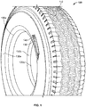
- Figure 1 illustrates a perspective view of one embodiment of a tire 100.
- the tire 100 has a circumferential tread 110 and a pair of beads 120, including a first bead 120a and a second bead 120b.
- a first sidewall 130a extends from the first bead 120a to the circumferential tread 110, and a second sidewall 130b extends from the second bead 120b to the circumferential tread 110.
- the first sidewall 130a includes external geometry configured for receiving an object.
- the external geometry is a rib 140 having a geometric shape that surrounds a flat portion 150.
- the rib only partially surrounds the flat portion. While the rib is shown as a substantially oval (or stadium) shape, having a plurality of circumferentially extending wings, it should be understood that any geometric shape may be employed.
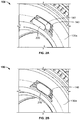
- Figures 2A and 2B illustrate partial perspective views of the tire 100 receiving an object 200.
- the object 200 is mounted in the flat portion 150 such that it is proximate to the rib 140.
- the object 200 may be any object.
- the object conveys information, such as through a visual indication, or through a bar code or other readable representation of data.
- the object is a tire electronic device such as an RFID chip or a sensor.
- the tire electronic device may be embedded in a polymeric material.
- An embedded electronic device may be referred to as a "tire electronic device package.”
- the tire electronic device is embedded in rubber.
- the tire electronic device is embedded in rubber having a substantially similar composition as the sidewall of the tire.
- a tire electronic device package need not include embedding material.
- the object 200 when the object 200 is mounted on the first sidewall 130a in the flat portion 150, the object 200 is exposed such that it is visible to an observer.
- the object 200 is a tire electronic device package that includes rubber that is substantially similar to the sidewall rubber, the object may not be immediately discernible as different from the surrounding sidewall, even though the object is visible.
- Figure 2C illustrates a partial side view of the tire 100.
- the rib 140 extends axially outward, beyond an outermost point of the object 200.
- the outermost point of the object 200 is a distance D 1 from an equatorial plane E of the tire 100
- an outer surface of the rib 140 is a distance D 2 from the equatorial plane E of the tire 100
- D 1 ⁇ D 2 the rib extends axially outward, beyond at least a portion of the object.
- the rib is flush with an outer surface of the object.
- the object protrudes beyond the rib.
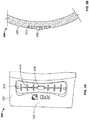
- Figure 3A illustrates a partial front view of an alternative embodiment of a tire 300 having a recess for receiving an object 400.
- Figures 3B-D are schematic drawings of partial cross sections of other alternative embodiments of a tire having a recess for receiving an object. While Figures 3A and 3B-D are not meant to be views of the same tire, they should be understood to illustrate similar features of the same concept.
- the tire 300 includes a recess 310 in a sidewall 320.
- the recess 310 has a shape configured to receive the object 400.
- both the recess 310 and the object 400 have a substantially dog bone shape.
- the recess and the object may have any geometric shape. It should also be understood that the shape of the object need not be the same as the shape of the recess.
- the object 400 is received in the recess 310 such that the sidewall 320 is flush with a portion of an outer surface of the object, while a portion of the object 400 protrudes beyond the sidewall 320.
- the object 400 is received in the recess 310 such that a portion of the sidewall proximate to the object 400 extends beyond the object. In other words, a distance from an equatorial plane of the tire 300 to a point on the object 400 is less than a distance from the equatorial plane of the tire 300 to a point on the sidewall 320 proximate to the object 400.
- the object 400 is completely flush with the sidewall 320. It should be understood that various portions of the object may be flush, recessed, or protrude from the sidewall of the tire.
- the object 400 may be any object, and may convey information through visual indication, a bar code, or other readable representation of data.
- the object 400 may also be a tire electronic device package and include an RFID chip or a sensor.
- the object 400 includes indicia 410 to indicate the purpose of the object to a user.
- the sidewall 320 of the tire 300 also includes indicia 330 to further indicate the purpose of the object to a user.
- both the object indicia 410 and the sidewall indicia 330 include symbols and/or lettering to indicate that the object includes an RFID tag, thereby informing the user where an RFID reader should be placed to obtain information.
- indicia may be employed to indicate communication information, such as the RF frequency, the RF protocol, the data format, or other information about the RFID tag. It should be understood that different indicia may be employed for other purposes.
- the object 400 when the object 400 is mounted on the sidewall 320, the object 400 is exposed such that it is visible to an observer.
- the object 400 is a tire electronic device package that includes rubber that is substantially similar to the sidewall rubber, the object may not be immediately discernible as different from the surrounding sidewall, even though the object is visible.
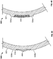
- Figure 4A illustrates a partial front view of an alternative embodiment of a tire 500 having a recess 510 for receiving an object 400 in a sidewall 520, as well as a pair of external ribs 530.
- Figure 4B is a schematic drawing of a partial cross section of another alternative embodiment of a tire 500 having a recess 510 for receiving an object 400, as well as a pair of external ribs 530.
- the tire 500 includes a recess 510 in a sidewall 520.
- the recess 510 has a shape configured to receive the object 400.
- both the recess 510 and the object 400 have a substantially dog bone shape.
- the recess and the object may have any geometric shape. It should also be understood that the shape of the object need not be the same as the shape of the recess.
- a pair of ribs 530 are disposed proximate to the recess 510, and are therefore proximate to the object 400.
- the pair of ribs 530 includes a first rib 530a proximate to a first side of the recess 510 and a second rib 530b proximate to a second side of the recess 510 opposite the first side of the recess.
- the ribs 530 extend outward beyond at least a portion of the object 400. In other words, a distance from an equatorial plane of the tire 500 to a point on the object 400 is less than a distance from the equatorial plane of the tire 500 to a point on the ribs 530.
- the ribs are flush with an outer surface of the object.
- the object protrudes beyond the ribs.
- the object 400 includes indicia 410 to indicate the purpose of the object to a user.
- the sidewall 520 of the tire 500 also includes indicia 540 to further indicate the purpose of the object to a user.
- both the object indicia 410 and the sidewall indicia 540 include symbols and/or lettering to indicate that the object includes an RFID chip, thereby informing the user where an RFID reader should be placed to obtain information. It should be understood that different indicia may be employed to indicate this, or other purposes.
- the object 400 when the object 400 is mounted on the sidewall 520, the object 400 is exposed such that it is visible to an observer.
- the object 400 is a tire electronic device package that includes rubber that is substantially similar to the sidewall rubber
- the object may not be immediately discernible as different from the surrounding sidewall, even though the object is visible.
- the object may include rubber, and is cured at the same time as the tire, the rubber of the object and the rubber of the sidewall may flow together such that there is no visible boundary between the object and the sidewall.
- Such an object may include an electronic device embedded therein. The object may still be said to be visible even if it the rubber of the object is indistinguishable from the rubber of the sidewall, and even if the embedded device is not visible.
- the object may be mounted on the side wall using one of a number of different methods.
- the tire is a cured tire, and the object is mounted in the recess or between the ribs using an adhesive, such as a solvent based adhesive, a polymer dispersion adhesive, a pressure sensitive adhesive, a contact adhesive, a thermoplastic, or a reactive adhesive.
- the object is press fit between the geometric ribs or the side walls of the recess.
- the tire is a green tire
- the object is placed in a recess in the mold or on the sidewall, and the tire and object are cured in a vulcanization mold such that the object adheres to the tire.
- Figures 5A-B illustrate an example of this method. It should be understood by those skilled in the art that a green tire is an assembled tire that has not been cured.
- Figure 5A illustrates a partial side view of one embodiment of a tire mold 600 having a sidewall forming portion 610.
- the sidewall forming portion 610 includes a segment 620 configured to receive the object 400.
- the mold 600 further includes geometry for forming corresponding features on a tire.
- mold 600 includes grooves 630 that form corresponding ribs on a tire.
- Alternative configurations may include recess forming portions, or both grooves and recess forming portions for creating other geometries in a tire for a receiving an object, such as the geometries shown in Figures 3-4 , or other geometries.
- the object 400 is retained against the segment 620 in a recess 640.
- a vacuum (not shown) is employed to provide suction through vacuum paths 650 to retain the object 400 against the segment 620.
- other mechanical or structural means are used to retain the object 400 against the segment 620.
- the object 400 may be disposed in a recess, between ribs, between posts, or between retractable grippers.
- one or more magnets (not shown) retain the object 400 against the segment 620.
- suction or electrostatics may be employed to retain the object 400 against the segment.
- the object may be placed on the green tire prior to curing, and the green tire is positioned such that the object aligns with appropriate geometry of the mold.
- adhesive may be employed to affix the object to the green tire.
- the green tire may be sufficiently tacky, such that adhesive is not required.
- the mold does not include any special geometry or means for retaining an object.
- the mold is oriented substantially horizontally, and the object may simply be positioned at a desired location on the mold. The object will remain in place due to gravity.
- the object may be placed on the green tire prior to curing
- Figure 5B illustrates a partial side view of one embodiment of a green tire 700 that is received in the tire mold 600.
- the green tire 700 includes a sidewall 710.
- a portion of the sidewall 710 contacts the object 400.
- the sidewall 710 and the object 400 are cured together such that the object 400 adheres to the sidewall 710.
- rubber also flows into the grooves 630 of the sidewall forming portion 610 of the mold 600, thereby forming ribs 720 on the sidewall 710 of the tire 700.
- Figure 6A illustrates a partial side view of a tire mold 800 having a sidewall forming portion 810.
- the sidewall forming portion 810 includes a pair of posts 820a,b configured to be received by slots in the object 400.
- the posts 820a,b thereby retain the object against a surface of the sidewall forming portion 810.
- the posts may be omitted.
- the sidewall forming portion 810 further includes indicia forming elements 830.
- the indicia forming elements 830 imprint corresponding indicia on a tire during the vulcanization process. Such indicia forming elements may be omitted.
- Figure 6B is a partial side view of a tire 900 that received the object 400 from the tire mold 800 during a vulcanization process.
- the tire 900 includes a sidewall 910 with a recess 920 formed therein.
- the object 400 is disposed in the recess 920 and has been affixed in this position through the curing process.
- the tire 900 further includes indicia 930 that were formed by the indicia forming elements 830 of the tire mold 800.
- the segment configured to receive the object is a removable segment that can be replaced with an alternative segment.
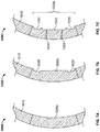
- Figures 7A-C are side views of one embodiment of a tire mold 1000 that utilizes one of a plurality of removable segments.
- the tire mold 1000 includes a sidewall forming portion 1010 having a removable segment 1020.
- a first removable segment 1020a has a plain face so that no geometric features would be formed on the green tire.
- a second removable segment 1020b includes grooves 1030 configured to form corresponding ribs on a green tire.
- the resulting tire would include geometry configured for receiving an object, such as the tire 100 shown in Figures 1-2 .
- Alternative configurations may include recess forming portions, or both grooves and recess forming portions for creating other geometries in a tire for a receiving an object, such as the geometries shown in Figures 3-4 , or other geometries.
- a third removable segment 1020c includes grooves 1030 configured to form corresponding ribs on a green tire, and further includes a recess 1040 for receiving an object.
- the third removable segment further includes vacuum paths 1050 for a vacuum (not shown) to provide suction to retain an object against the segment 1020c.
- other retention means may be employed, such as those described above with reference to Figures 5A-B .
- other forming portions may be employed for creating other geometries in a tire for a receiving an object, such as the geometries shown in Figures 3-4 , or other geometries.
- Figures 8A-B illustrate side views of an alternative embodiment of a tire 1100 having external geometry for receiving an object 1200.
- the tire 1100 has a sidewall 1110 with outer ribs 1120 and flexible inner ribs 1130 configured to receive the object.
- the object 1200 includes barbs 1210.
- the flexible inner ribs 1130 are spaced such that the introduction of the object 1200 causes the flexible inner ribs 1130 to separate.
- the material properties of the flexible inner ribs 1130 bias them towards each other when separated.
- the barbs 1210 engage the flexible inner ribs 1130, thereby causing a force fit.
Landscapes
- Engineering & Computer Science (AREA)
- Mechanical Engineering (AREA)
- Tires In General (AREA)
- Moulds For Moulding Plastics Or The Like (AREA)
- Portable Nailing Machines And Staplers (AREA)
- Measuring Fluid Pressure (AREA)
Abstract

Description
- The present disclosure relates to the field of attaching an object to a tire. More particularly, the present disclosure relates to tire structure for externally mounting an object to the tire.
- It is sometimes desirable to attach an object to a tire. For example, it may be desirable to attach an electronic device package, such as a radio device, to a tire. In one such embodiment, the radio device is a radio frequency identification (RFID) tag or chip to a tire. Such a device package may be embedded in the sidewall or other location of a tire, such that the chip is not visible to an observer. Alternatively, a device package may be attached to an external or internal surface of the tire. In one known embodiment, the device package is attached to an external surface of a sidewall using an adhesive.
- In one embodiment, a tire has a circumferential tread and a pair of beads, including a first bead and a second bead. The tire further includes a pair of sidewalls, including a first sidewall extending from the first bead to the circumferential tread, and a second sidewall extending from the second bead to the circumferential tread. A tire electronic device package is mounted to an external side of the first sidewall, at a location between the first bead and the circumferential tread. The tire electronic device package is exposed, such that the tire electronic device package is visible. A distance from an equatorial plane of the tire to a point on the sidewall proximate to the tire electronic device package is at least as great as a distance from the equatorial plane of the tire to a point on an external surface of the tire electronic device package.
- In another embodiment, a tire mold includes a circumferential tread forming portion and a pair of sidewall forming portions. One of the sidewall forming portions includes a segment configured to receive an object. The tire mold further includes means for retaining the object against the segment such that at least a portion of the object is disposed inward from at least a portion of the segment configured to receive the object.
- In yet another embodiment, a method of mounting an object on a tire includes providing a tire having a sidewall, wherein the sidewall includes a mounting portion configured to receive an object. The method further includes mounting the object on the mounting portion of the sidewall, such that the object is visible without extending outwardly beyond the mounting portion.
- In still another embodiment, a method of mounting an object on a tire includes providing a green tire having a sidewall and mounting the object on an external surface of the sidewall, such that the object is visible. The method further includes curing the green tire and the object together.
- In the accompanying drawings, structures are illustrated that, together with the detailed description provided below, describe exemplary embodiments of the claimed invention. Like elements are identified with the same reference numerals. It should be understood that elements shown as a single component may be replaced with multiple components, and elements shown as multiple components may be replaced with a single component. The drawings are not to scale and the proportion of certain elements may be exaggerated for the purpose of illustration.
-
Figure 1 is a perspective view of one embodiment of atire 100 having external geometry configured for receiving an object; -
Figures 2A-B are partial perspective views of thetire 100 receiving an object; -
Figure 2C is a partial side view of thetire 100; -
Figure 3A is a partial front view of an alternative embodiment of a tire having a recess for receiving an object; -
Figures 3B-D are schematic drawings of partial cross sections of other alternative embodiments of a tire having a recess for receiving an object; -
Figure 4A is a partial front view of an alternative embodiment of a tire having a pair of external ribs and a recess for receiving an object; -
Figures 4B-D are schematic drawings of partial cross sections of other alternative embodiments of a tire having a pair of external ribs and a recess for receiving an object; -
Figure 5A is a partial side view of one embodiment of atire mold 600 having internal geometry configured for receiving an object; -
Figure 5B is a partial side view of one embodiment of a tire having external geometry configured for receiving the object from thetire mold 600; -
Figure 6A is a partial side view of an alternative embodiment of atire mold 800 and an object received by internal geometry of the mold; -
Figure 6B is a partial side view of an alternative embodiment of a tire that received an object from thetire mold 800 during a vulcanization process; -
Figures 7A-C are a side views of one embodiment of a tire mold that utilizes a plurality of removable segments; and -
Figures 8A-B are side views of an alternative embodiment of a tire having external geometry for receiving an object. - The following includes definitions of selected terms employed herein. The definitions include various examples or forms of components that fall within the scope of a term and that may be used for implementation. The examples are not intended to be limiting. Both singular and plural forms of terms may be within the definitions. Where the definitions include a reference to a tire, it should be understood to also reference a tire mold.
- "Axial" or "axially" refer to a direction that is parallel to the axis of rotation of a tire.
- "Bead" refers to the part of the tire that contacts the wheel and defines a boundary of the sidewall.
- "Circumferential" and "circumferentially" refer to a direction extending along the perimeter of the surface of the tread perpendicular to the axial direction.
- "Equatorial plane" refers to the plane that is perpendicular to the tire's axis of rotation and passes through the center of the tire's tread.
- "Radial" and "radially" refer to a direction perpendicular to the axis of rotation of a tire.
- "Sidewall" refers to that portion of the tire between the tread and the bead.
- "Tread" refers to that portion of the tire that comes into contact with the road under normal inflation and load.
- Directions are stated herein with reference to the axis of rotation of the tire. The terms "upward" and "upwardly" refer to a general direction towards the tread of the tire, whereas "downward" and "downwardly" refer to the general direction towards the axis of rotation of the tire. Thus, when relative directional terms such as "upper" and "lower" or "top" and "bottom" are used in connection with an element, the "upper" or "top" element is spaced closer to the tread than the "lower" or "bottom" element. Additionally, when relative directional terms such as "above" or "below" are used in connection with an element, an element that is "above" another element is closer to the tread than the other element.
- The terms "inward" and "inwardly" refer to a general direction towards the equatorial plane of the tire, whereas "outward" and "outwardly" refer to a general direction away from the equatorial plane of the tire and towards the sidewall of the tire. Thus, when relative directional terms such as "inner" and "outer" are used in connection with an element, the "inner" element is spaced closer to the equatorial plane of the tire than the "outer" element.
-
Figure 1 illustrates a perspective view of one embodiment of atire 100. Thetire 100 has acircumferential tread 110 and a pair of beads 120, including afirst bead 120a and asecond bead 120b. Afirst sidewall 130a extends from thefirst bead 120a to thecircumferential tread 110, and asecond sidewall 130b extends from thesecond bead 120b to thecircumferential tread 110. - The
first sidewall 130a includes external geometry configured for receiving an object. In the illustrated embodiment, the external geometry is arib 140 having a geometric shape that surrounds aflat portion 150. In an alternative embodiment (not shown), the rib only partially surrounds the flat portion. While the rib is shown as a substantially oval (or stadium) shape, having a plurality of circumferentially extending wings, it should be understood that any geometric shape may be employed. -
Figures 2A and 2B illustrate partial perspective views of thetire 100 receiving anobject 200. As can be seen from these figures, theobject 200 is mounted in theflat portion 150 such that it is proximate to therib 140. - The
object 200 may be any object. In one known embodiment, the object conveys information, such as through a visual indication, or through a bar code or other readable representation of data. In another known embodiment, the object is a tire electronic device such as an RFID chip or a sensor. The tire electronic device may be embedded in a polymeric material. An embedded electronic device may be referred to as a "tire electronic device package." In one embodiment, the tire electronic device is embedded in rubber. In one specific embodiment, the tire electronic device is embedded in rubber having a substantially similar composition as the sidewall of the tire. However, it should be understood that a tire electronic device package need not include embedding material. - As can be seen in
Figure 2B , when theobject 200 is mounted on thefirst sidewall 130a in theflat portion 150, theobject 200 is exposed such that it is visible to an observer. However, it should be understood that in the case where theobject 200 is a tire electronic device package that includes rubber that is substantially similar to the sidewall rubber, the object may not be immediately discernible as different from the surrounding sidewall, even though the object is visible. -
Figure 2C illustrates a partial side view of thetire 100. As can be seen from this view, in the illustrated embodiment, therib 140 extends axially outward, beyond an outermost point of theobject 200. In other words, the outermost point of theobject 200 is a distance D1 from an equatorial plane E of thetire 100, an outer surface of therib 140 is a distance D2 from the equatorial plane E of thetire 100, and D1 < D2 . In an alternative embodiment (not shown), the rib extends axially outward, beyond at least a portion of the object. In another alternative embodiment (not shown), the rib is flush with an outer surface of the object. In yet another alternative embodiment (not shown), the object protrudes beyond the rib. -
Figure 3A illustrates a partial front view of an alternative embodiment of atire 300 having a recess for receiving anobject 400. Additionally,Figures 3B-D are schematic drawings of partial cross sections of other alternative embodiments of a tire having a recess for receiving an object. WhileFigures 3A and3B-D are not meant to be views of the same tire, they should be understood to illustrate similar features of the same concept. - In the illustrated embodiment, the
tire 300 includes arecess 310 in asidewall 320. Therecess 310 has a shape configured to receive theobject 400. In the illustrated embodiment, both therecess 310 and theobject 400 have a substantially dog bone shape. However, it should be understood that the recess and the object may have any geometric shape. It should also be understood that the shape of the object need not be the same as the shape of the recess. - In one embodiment, shown in
Figure 3B , theobject 400 is received in therecess 310 such that thesidewall 320 is flush with a portion of an outer surface of the object, while a portion of theobject 400 protrudes beyond thesidewall 320. In another embodiment, shown inFigure 3C , theobject 400 is received in therecess 310 such that a portion of the sidewall proximate to theobject 400 extends beyond the object. In other words, a distance from an equatorial plane of thetire 300 to a point on theobject 400 is less than a distance from the equatorial plane of thetire 300 to a point on thesidewall 320 proximate to theobject 400. In yet another embodiment, shown inFigure 3D , theobject 400 is completely flush with thesidewall 320. It should be understood that various portions of the object may be flush, recessed, or protrude from the sidewall of the tire. - Like the embodiment shown in
Figures 1 and2 , theobject 400 may be any object, and may convey information through visual indication, a bar code, or other readable representation of data. Theobject 400 may also be a tire electronic device package and include an RFID chip or a sensor. In the illustrated embodiment, theobject 400 includesindicia 410 to indicate the purpose of the object to a user. Thesidewall 320 of thetire 300 also includesindicia 330 to further indicate the purpose of the object to a user. In the illustrated example, both theobject indicia 410 and thesidewall indicia 330 include symbols and/or lettering to indicate that the object includes an RFID tag, thereby informing the user where an RFID reader should be placed to obtain information. Additionally, or in the alternative, indicia may be employed to indicate communication information, such as the RF frequency, the RF protocol, the data format, or other information about the RFID tag. It should be understood that different indicia may be employed for other purposes. - In the illustrated embodiment, when the
object 400 is mounted on thesidewall 320, theobject 400 is exposed such that it is visible to an observer. However, it should be understood that in the case where theobject 400 is a tire electronic device package that includes rubber that is substantially similar to the sidewall rubber, the object may not be immediately discernible as different from the surrounding sidewall, even though the object is visible. -
Figure 4A illustrates a partial front view of an alternative embodiment of atire 500 having arecess 510 for receiving anobject 400 in asidewall 520, as well as a pair of external ribs 530.Figure 4B is a schematic drawing of a partial cross section of another alternative embodiment of atire 500 having arecess 510 for receiving anobject 400, as well as a pair of external ribs 530. - In the illustrated embodiment, the
tire 500 includes arecess 510 in asidewall 520. Therecess 510 has a shape configured to receive theobject 400. In the illustrated embodiment, both therecess 510 and theobject 400 have a substantially dog bone shape. However, it should be understood that the recess and the object may have any geometric shape. It should also be understood that the shape of the object need not be the same as the shape of the recess. - Additionally, a pair of ribs 530 are disposed proximate to the
recess 510, and are therefore proximate to theobject 400. The pair of ribs 530 includes afirst rib 530a proximate to a first side of therecess 510 and asecond rib 530b proximate to a second side of therecess 510 opposite the first side of the recess. The ribs 530 extend outward beyond at least a portion of theobject 400. In other words, a distance from an equatorial plane of thetire 500 to a point on theobject 400 is less than a distance from the equatorial plane of thetire 500 to a point on the ribs 530. In an alternative embodiment (not shown), the ribs are flush with an outer surface of the object. In yet another alternative embodiment (not shown), the object protrudes beyond the ribs. - In the illustrated embodiment, the
object 400 includesindicia 410 to indicate the purpose of the object to a user. Thesidewall 520 of thetire 500 also includesindicia 540 to further indicate the purpose of the object to a user. In the illustrated example, both theobject indicia 410 and thesidewall indicia 540 include symbols and/or lettering to indicate that the object includes an RFID chip, thereby informing the user where an RFID reader should be placed to obtain information. It should be understood that different indicia may be employed to indicate this, or other purposes. - In the illustrated embodiment, when the
object 400 is mounted on thesidewall 520, theobject 400 is exposed such that it is visible to an observer. However, it should be understood that in the case where theobject 400 is a tire electronic device package that includes rubber that is substantially similar to the sidewall rubber, the object may not be immediately discernible as different from the surrounding sidewall, even though the object is visible. Indeed, if the object includes rubber, and is cured at the same time as the tire, the rubber of the object and the rubber of the sidewall may flow together such that there is no visible boundary between the object and the sidewall. Such an object may include an electronic device embedded therein. The object may still be said to be visible even if it the rubber of the object is indistinguishable from the rubber of the sidewall, and even if the embedded device is not visible. - In each of the above described embodiments shown in
Figures 1-4 , the object may be mounted on the side wall using one of a number of different methods. In one embodiment, the tire is a cured tire, and the object is mounted in the recess or between the ribs using an adhesive, such as a solvent based adhesive, a polymer dispersion adhesive, a pressure sensitive adhesive, a contact adhesive, a thermoplastic, or a reactive adhesive. In another alternative embodiment, the object is press fit between the geometric ribs or the side walls of the recess. - In an alternative embodiment, the tire is a green tire, and the object is placed in a recess in the mold or on the sidewall, and the tire and object are cured in a vulcanization mold such that the object adheres to the tire.
Figures 5A-B illustrate an example of this method. It should be understood by those skilled in the art that a green tire is an assembled tire that has not been cured. -
Figure 5A illustrates a partial side view of one embodiment of atire mold 600 having asidewall forming portion 610. Thesidewall forming portion 610 includes asegment 620 configured to receive theobject 400. Themold 600 further includes geometry for forming corresponding features on a tire. For example,mold 600 includesgrooves 630 that form corresponding ribs on a tire. Alternative configurations may include recess forming portions, or both grooves and recess forming portions for creating other geometries in a tire for a receiving an object, such as the geometries shown inFigures 3-4 , or other geometries. - In the illustrated embodiment, the
object 400 is retained against thesegment 620 in arecess 640. In the illustrated embodiment, a vacuum (not shown) is employed to provide suction through vacuum paths 650 to retain theobject 400 against thesegment 620. In an alternative embodiment, other mechanical or structural means are used to retain theobject 400 against thesegment 620. For example, theobject 400 may be disposed in a recess, between ribs, between posts, or between retractable grippers. In another alternative embodiment, one or more magnets (not shown) retain theobject 400 against thesegment 620. In yet another alternative embodiment, suction or electrostatics may be employed to retain theobject 400 against the segment. - In an alternative embodiment, the object may be placed on the green tire prior to curing, and the green tire is positioned such that the object aligns with appropriate geometry of the mold. In such an embodiment, adhesive may be employed to affix the object to the green tire. Alternatively, the green tire may be sufficiently tacky, such that adhesive is not required.
- In an alternative embodiment (not shown), the mold does not include any special geometry or means for retaining an object. Instead, in one embodiment, the mold is oriented substantially horizontally, and the object may simply be positioned at a desired location on the mold. The object will remain in place due to gravity. In an alternative embodiment, the object may be placed on the green tire prior to curing
-
Figure 5B illustrates a partial side view of one embodiment of agreen tire 700 that is received in thetire mold 600. Thegreen tire 700 includes asidewall 710. When thegreen tire 700 is placed in the mold, a portion of thesidewall 710 contacts theobject 400. During vulcanization of thegreen tire 700, thesidewall 710 and theobject 400 are cured together such that theobject 400 adheres to thesidewall 710. During the vulcanization process, rubber also flows into thegrooves 630 of thesidewall forming portion 610 of themold 600, thereby formingribs 720 on thesidewall 710 of thetire 700. - One specific example of a tire and tire mold is shown in
Figures 6A-B. Figure 6A illustrates a partial side view of atire mold 800 having asidewall forming portion 810. Thesidewall forming portion 810 includes a pair ofposts 820a,b configured to be received by slots in theobject 400. Theposts 820a,b thereby retain the object against a surface of thesidewall forming portion 810. In an alternative embodiment (not shown) the posts may be omitted. - In the illustrated embodiment, the
sidewall forming portion 810 further includesindicia forming elements 830. Theindicia forming elements 830 imprint corresponding indicia on a tire during the vulcanization process. Such indicia forming elements may be omitted. -
Figure 6B is a partial side view of atire 900 that received theobject 400 from thetire mold 800 during a vulcanization process. As can be seen from this illustration, thetire 900 includes asidewall 910 with arecess 920 formed therein. Theobject 400 is disposed in therecess 920 and has been affixed in this position through the curing process. Thetire 900 further includesindicia 930 that were formed by theindicia forming elements 830 of thetire mold 800. - It may be desirable for a manufacturer to produce different batches of the same tire model, with different features in the sidewall. For example, a first market may not desire to have an object on a sidewall, a second market may desire to mount an existing object on a tire sidewall, and a third market may desire tires that already have objects mounted on the sidewall. Therefore, in one embodiment of the tire mold, the segment configured to receive the object is a removable segment that can be replaced with an alternative segment.
-
Figures 7A-C are side views of one embodiment of atire mold 1000 that utilizes one of a plurality of removable segments. In each figure, thetire mold 1000 includes asidewall forming portion 1010 having a removable segment 1020. In a first configuration, shown inFigure 7A , a firstremovable segment 1020a has a plain face so that no geometric features would be formed on the green tire. In a second configuration, shown inFigure 7B , a secondremovable segment 1020b includesgrooves 1030 configured to form corresponding ribs on a green tire. When the secondremovable segment 1020b is employed, the resulting tire would include geometry configured for receiving an object, such as thetire 100 shown inFigures 1-2 . Alternative configurations may include recess forming portions, or both grooves and recess forming portions for creating other geometries in a tire for a receiving an object, such as the geometries shown inFigures 3-4 , or other geometries. - In a third configuration, shown in
Figure 7C , a thirdremovable segment 1020c includesgrooves 1030 configured to form corresponding ribs on a green tire, and further includes arecess 1040 for receiving an object. The third removable segment further includesvacuum paths 1050 for a vacuum (not shown) to provide suction to retain an object against thesegment 1020c. Alternatively, other retention means may be employed, such as those described above with reference toFigures 5A-B . Additionally, other forming portions may be employed for creating other geometries in a tire for a receiving an object, such as the geometries shown inFigures 3-4 , or other geometries. -
Figures 8A-B illustrate side views of an alternative embodiment of atire 1100 having external geometry for receiving anobject 1200. Thetire 1100 has asidewall 1110 withouter ribs 1120 and flexibleinner ribs 1130 configured to receive the object. In the illustrated embodiment, theobject 1200 includesbarbs 1210. The flexibleinner ribs 1130 are spaced such that the introduction of theobject 1200 causes the flexibleinner ribs 1130 to separate. The material properties of the flexibleinner ribs 1130 bias them towards each other when separated. Thebarbs 1210 engage the flexibleinner ribs 1130, thereby causing a force fit. - To the extent that the term "includes" or "including" is used in the specification or the claims, it is intended to be inclusive in a manner similar to the term "comprising" as that term is interpreted when employed as a transitional word in a claim. Furthermore, to the extent that the term "or" is employed (e.g., A or B) it is intended to mean "A or B or both." When the applicants intend to indicate "only A or B but not both" then the term "only A or B but not both" will be employed. Thus, use of the term "or" herein is the inclusive, and not the exclusive use. See, Bryan A. Garner, A Dictionary of Modern Legal Usage 624 (2d. Ed. 1995). Also, to the extent that the terms "in" or "into" are used in the specification or the claims, it is intended to additionally mean "on" or "onto." Furthermore, to the extent the term "connect" is used in the specification or claims, it is intended to mean not only "directly connected to," but also "indirectly connected to" such as connected through another component or components.
- While the present application has been illustrated by the description of embodiments thereof, and while the embodiments have been described in considerable detail, it is not the intention of the applicants to restrict or in any way limit the scope of the appended claims to such detail. Additional advantages and modifications will readily appear to those skilled in the art. Therefore, the application, in its broader aspects, is not limited to the specific details, the representative apparatus and method, and illustrative examples shown and described. Accordingly, departures may be made from such details without departing from the spirit or scope of the applicant's general inventive concept.
- Further embodiments of the present invention are set out in the following clauses:
- (1) A tire comprising:
- a circumferential tread;
- a pair of beads, including a first bead and a second bead;
- a pair of sidewalls, including a first sidewall extending from the first bead to the circumferential tread, and a second sidewall extending from the second bead to the circumferential tread;
- a tire electronic device package mounted to an external side of the first sidewall, at a location between the first bead and the circumferential tread,
- wherein the tire electronic device package is exposed, such that the tire electronic device package is visible, and
- wherein a distance from an equatorial plane of the tire to a point on the first sidewall proximate to the tire electronic device package is at least as great as a distance from the equatorial plane of the tire to a point on an external surface of the tire electronic device package.
- (2) The tire of clause 1, wherein the tire electronic device package is mounted in a recess of the first sidewall.
- (3) The tire of clause 2, wherein the first sidewall further includes at least one rib proximate to the recess.
- (4) The tire of clause 3, wherein the at least one rib has a geometric shape and at least partially surrounds the recess.
- (5) The tire of clause 3, wherein the at least one rib includes a first rib proximate to a first side of the recess and a second rib proximate to a second side of the recess opposite the first side of the recess.
- (6) The tire of clause 1, wherein the first sidewall further includes at least one rib proximate to the tire electronic device package.
- (7) The tire of clause 6, wherein the at least one rib has a geometric shape and at least partially surrounds the tire electronic device package.
- (8) The tire of clause 6, wherein the at least one rib includes a first rib proximate to a first side of the tire electronic device package and a second rib proximate to a second side of the tire electronic device package opposite the first side of the tire electronic device package.
- (9) A tire mold comprising:
- a circumferential tread forming portion; and
- a pair of sidewall forming portions, wherein one of the sidewall forming portions includes a segment configured to receive an object;
- means for retaining the object against the segment such that at least a portion of the object is disposed inward from at least a portion of the segment configured to receive the object.
- (10) The tire mold of clause 9, wherein the segment configured to receive the object is a removable segment.
- (11) The tire mold of clause 10, further comprising a replacement segment incapable of receiving an object.
- (12) The tire mold of clause 9, wherein the means for retaining the object is a magnetic means for retaining the object.
- (13) The tire mold of clause 9, wherein the means for retaining the object is a mechanical means for retaining the object.
- (14) The tire mold of clause 9, wherein the tire mold is configured to receive a green tire in a manner such that the object contacts the green tire.
- (15) A method of mounting an object on a tire comprising:
- providing a tire having a sidewall, the sidewall including a mounting portion configured to receive the object;
- mounting the object on the mounting portion of the sidewall, such that the object is visible without extending outwardly beyond the mounting portion.
- (16) The method of clause 15, wherein the tire is a cured tire and wherein the mounting the object on the mounting portion of the sidewall includes using adhesive to mount the object to the mounting portion of the sidewall.
- (17) A method of mounting an object on a tire comprising:
- providing a green tire having a sidewall;
- mounting the object on an external surface of the sidewall, such that the object is visible; and
- curing the green tire and the object together.
- (18) The method of clause 17, wherein the mounting the object on the sidewall includes positioning the object on a sidewall forming portion of a mold, and placing the green tire in the mold such that the sidewall contacts the object.
- (19) The method of clause 18, wherein the positioning the object on the sidewall forming portion of the mold includes retaining the object on the sidewall forming portion of the mold with a magnet.
- (20) The method of clause 17, wherein the object is placed on the green tire prior to placing the green tire in a mold.
- (21) The method of clause 20, further comprising positioning the green tire in the mold such that the object is aligned with a sidewall geometry forming portion of the mold.
Claims (9)
- A tire mold comprising:a circumferential tread forming portion; anda pair of sidewall forming portions, wherein one of the sidewall forming portions includes a segment configured to receive an object;means for retaining the object against the segment such that at least a portion of the object is disposed inward from at least a portion of the segment configured to receive the object.
- The tire mold of claim 1, wherein the segment configured to receive the object is a removable segment, optionally wherein the tire mold further comprises a replacement segment incapable of receiving an object.
- The tire mold of claim 1, wherein the means for retaining the object is a magnetic means for retaining the object, or wherein the means for retaining the object is a mechanical means for retaining the object.
- The tire mold of claim 1, wherein the tire mold is configured to receive a green tire in a manner such that the object contacts the green tire.
- A method of mounting an object on a tire comprising:providing a tire having a sidewall, the sidewall including a mounting portion configured to receive the object;mounting the object on the mounting portion of the sidewall, such that the object is visible without extending outwardly beyond the mounting portion.
- The method of claim 5, wherein the tire is a cured tire and wherein the mounting the object on the mounting portion of the sidewall includes using adhesive to mount the object to the mounting portion of the sidewall.
- A method of mounting an object on a tire comprising:providing a green tire having a sidewall;mounting the object on an external surface of the sidewall, such that the object is visible; andcuring the green tire and the object together.
- The method of claim 7, wherein the mounting the object on the sidewall includes positioning the object on a sidewall forming portion of a mold, and placing the green tire in the mold such that the sidewall contacts the object, optionally wherein the positioning the object on the sidewall forming portion of the mold includes retaining the object on the sidewall forming portion of the mold with a magnet.
- The method of claim 7, wherein the object is placed on the green tire prior to placing the green tire in a mold, optionally wherein the method further comprises positioning the green tire in the mold such that the object is aligned with a sidewall geometry forming portion of the mold.
Applications Claiming Priority (3)
| Application Number | Priority Date | Filing Date | Title |
|---|---|---|---|
| US14/028,699 US9827724B2 (en) | 2013-09-17 | 2013-09-17 | Tire structure for externally mounted device |
| EP14845260.0A EP3046782B1 (en) | 2013-09-17 | 2014-07-31 | Tire structure for externally mounted device |
| PCT/US2014/049004 WO2015041756A1 (en) | 2013-09-17 | 2014-07-31 | Tire structure for externally mounted device |
Related Parent Applications (2)
| Application Number | Title | Priority Date | Filing Date |
|---|---|---|---|
| EP14845260.0A Division EP3046782B1 (en) | 2013-09-17 | 2014-07-31 | Tire structure for externally mounted device |
| EP14845260.0A Division-Into EP3046782B1 (en) | 2013-09-17 | 2014-07-31 | Tire structure for externally mounted device |
Publications (1)
| Publication Number | Publication Date |
|---|---|
| EP3778266A1 true EP3778266A1 (en) | 2021-02-17 |
Family
ID=52666878
Family Applications (2)
| Application Number | Title | Priority Date | Filing Date |
|---|---|---|---|
| EP14845260.0A Active EP3046782B1 (en) | 2013-09-17 | 2014-07-31 | Tire structure for externally mounted device |
| EP20198106.5A Pending EP3778266A1 (en) | 2013-09-17 | 2014-07-31 | Tire structure for externally mounted device |
Family Applications Before (1)
| Application Number | Title | Priority Date | Filing Date |
|---|---|---|---|
| EP14845260.0A Active EP3046782B1 (en) | 2013-09-17 | 2014-07-31 | Tire structure for externally mounted device |
Country Status (11)
| Country | Link |
|---|---|
| US (2) | US9827724B2 (en) |
| EP (2) | EP3046782B1 (en) |
| JP (1) | JP6328771B2 (en) |
| KR (1) | KR20160044544A (en) |
| CN (1) | CN105555552B (en) |
| AR (1) | AR097674A1 (en) |
| BR (1) | BR112016005676B1 (en) |
| CA (1) | CA2923687C (en) |
| MX (1) | MX2016003399A (en) |
| RU (1) | RU2016109029A (en) |
| WO (1) | WO2015041756A1 (en) |
Cited By (1)
| Publication number | Priority date | Publication date | Assignee | Title |
|---|---|---|---|---|
| FR3130198A1 (en) * | 2021-12-14 | 2023-06-16 | Compagnie Generale Des Etablissements Michelin | TIRE FEATURING AN IMPROVED STYLING SIDEWALL |
Families Citing this family (32)
| Publication number | Priority date | Publication date | Assignee | Title |
|---|---|---|---|---|
| KR102255579B1 (en) | 2012-11-13 | 2021-05-25 | 쿠퍼 타이어 앤드 러버 캄파니 | Product such as a tire with rfid tag with rubber, elastomer, or polymer antenna |
| DE102014214139A1 (en) * | 2014-07-21 | 2016-01-21 | Benchmark Drives GmbH & Co. KG | Tires, in particular two-wheeled tires, with a device for generating rotation-dependent signals, method for its production and system for controlling a two-wheel drive with such a tire |
| EP3411222B1 (en) * | 2016-02-03 | 2020-10-28 | Cooper Tire & Rubber Company | Rfid tagged tire curing bladders |
| USD798226S1 (en) * | 2016-09-28 | 2017-09-26 | Bridgestone Americas Tire Operatons, Llc | Tire tread |
| JP6747932B2 (en) * | 2016-10-11 | 2020-08-26 | Toyo Tire株式会社 | Pneumatic tire |
| US11548329B2 (en) * | 2017-05-23 | 2023-01-10 | Shandong Linglong Tyre Co., Ltd. | Intelligent tire |
| US20190135011A1 (en) * | 2017-11-03 | 2019-05-09 | The Goodyear Tire & Rubber Company | Quiet zone for digital code pattern on a rubber article |
| US20190244074A1 (en) * | 2018-02-02 | 2019-08-08 | FineLine Technologies | Foam-based rfid label |
| US11679571B2 (en) * | 2018-05-17 | 2023-06-20 | Compagnie Generale Des Etablissements Michelin | Method for producing a tire provided with a radiofrequency communications module |
| CN112469577A (en) * | 2018-07-24 | 2021-03-09 | 横滨橡胶株式会社 | Pneumatic tire and method for manufacturing same |
| US10919348B2 (en) * | 2018-09-05 | 2021-02-16 | The Goodyear Tire & Rubber Company | Tire with RFID locator |
| WO2020075469A1 (en) * | 2018-10-10 | 2020-04-16 | 株式会社梅垣ラベルサービス | Rf tag label and rubber product equipped with rf tag label |
| WO2020075732A1 (en) * | 2018-10-10 | 2020-04-16 | 株式会社フェニックスソリューション | Rf tag for embedding in tire, and rf-tagged tire |
| JP7410488B2 (en) * | 2019-06-24 | 2024-01-10 | 株式会社Uls | RF tag labels and rubber products with RF tag labels |
| US11235625B2 (en) * | 2018-10-29 | 2022-02-01 | International Business Machines Corporation | Implementing tire tread depth and wear patterns monitoring with RFID |
| KR102080442B1 (en) * | 2019-06-28 | 2020-02-21 | 한국타이어앤테크놀로지 주식회사 | Tire integrated with electronic device and manufacturing method thereof |
| US12187001B2 (en) * | 2019-12-19 | 2025-01-07 | Compagnie Generale Des Etablissements Michelin | Method of molding a container into a tire |
| FR3114772B1 (en) * | 2020-10-01 | 2022-10-07 | Michelin & Cie | Tire including a sidewall insert |
| FR3114773B1 (en) * | 2020-10-01 | 2023-04-21 | Michelin & Cie | Tire including a sidewall insert |
| KR102503810B1 (en) | 2021-02-04 | 2023-02-24 | 한국타이어앤테크놀로지 주식회사 | Electronic tire with electronic device attached, method of attaching electronic device thereof, and method of interlocking with cloud thereof |
| USD1001726S1 (en) * | 2021-04-19 | 2023-10-17 | Continental Reifen Deustschland Gmbh | Sidewall of a tire with graphic symbol |
| JP7656505B2 (en) * | 2021-06-30 | 2025-04-03 | 株式会社ブリヂストン | tire |
| JP7671658B2 (en) * | 2021-09-13 | 2025-05-02 | 株式会社ブリヂストン | tire |
| JP7701867B2 (en) * | 2021-12-09 | 2025-07-02 | 株式会社ブリヂストン | tire |
| JP7695182B2 (en) * | 2021-12-13 | 2025-06-18 | 株式会社ブリヂストン | tire |
| EP4197768B1 (en) * | 2021-12-15 | 2026-02-11 | Continental Reifen Deutschland GmbH | Rubber product for moving applications with a sensor |
| JP2024015903A (en) * | 2022-07-25 | 2024-02-06 | 株式会社ブリヂストン | Tire manufacturing method and tires |
| KR102756120B1 (en) * | 2022-10-13 | 2025-01-21 | 넥센타이어 주식회사 | Tire wiht detachable rfid tags |
| FR3147145A1 (en) * | 2023-03-29 | 2024-10-04 | Compagnie Generale Des Etablissements Michelin | Pneumatic tire including a sidewall insert |
| FR3150141A1 (en) * | 2023-06-20 | 2024-12-27 | Compagnie Generale Des Etablissements Michelin | Pneumatic tire including a sidewall insert |
| FR3150142A1 (en) * | 2023-06-20 | 2024-12-27 | Compagnie Generale Des Etablissements Michelin | Method of installing a sidewall insert on a tire |
| WO2025085297A1 (en) * | 2023-10-19 | 2025-04-24 | Compagnie Generale Des Etablissements Michelin | Method for use in molding a container into a tire |
Citations (6)
| Publication number | Priority date | Publication date | Assignee | Title |
|---|---|---|---|---|
| EP0213478A2 (en) * | 1985-08-16 | 1987-03-11 | The Firestone Tire & Rubber Company | Apparatus for introducing appliques to the sidewall of a tire |
| EP0249918A2 (en) * | 1986-06-17 | 1987-12-23 | The Firestone Tire & Rubber Company | Premolded tire sidewall appliques and process for applying same |
| DE4429216A1 (en) * | 1994-08-18 | 1996-02-22 | Uniroyal Englebert Gmbh | Tyre with non-permanently attached data carrier |
| EP0689950B1 (en) * | 1994-06-03 | 1999-04-28 | BRIDGESTONE/FIRESTONE, Inc. | Method of monitoring conditions of vehicle tires and tires containing a monitoring device therein |
| WO2009007790A1 (en) * | 2007-07-11 | 2009-01-15 | Pirelli Tyre S.P.A. | Process and apparatus for vulcanization and moulding of vehicles tyres |
| JP2013107460A (en) * | 2011-11-18 | 2013-06-06 | Sumitomo Rubber Ind Ltd | Pneumatic tire |
Family Cites Families (47)
| Publication number | Priority date | Publication date | Assignee | Title |
|---|---|---|---|---|
| US1458629A (en) * | 1922-11-20 | 1923-06-12 | Goodrich Co B F | Vehicle tire |
| JPS516712A (en) * | 1974-07-06 | 1976-01-20 | Aiwa Co | Johosaisei kirokusochi |
| JPS59165180A (en) * | 1983-03-10 | 1984-09-18 | Yokohama Rubber Co Ltd:The | Reading method of bar code for tire selection |
| JPS6181207A (en) * | 1984-09-28 | 1986-04-24 | Yokohama Rubber Co Ltd:The | Pneumatic tire |
| US4851809A (en) * | 1988-11-07 | 1989-07-25 | Suzanne Goggans | Tire inflation indicator |
| JPH0899508A (en) * | 1994-09-30 | 1996-04-16 | Bridgestone Corp | Pneumatic tire |
| US6030478A (en) | 1998-02-10 | 2000-02-29 | Bridgestone/Firestone, Inc. | Method and apparatus for removably inserting an electric tire tag into a tire |
| US6581657B1 (en) | 1999-08-16 | 2003-06-24 | The Goodyear Tire & Rubber Company | Disposition of transponder coupling elements in tires |
| EP1617197B8 (en) | 2001-07-10 | 2009-04-15 | Commissariat A L'energie Atomique | Tyre incorporating a force measuring device |
| US20040095244A1 (en) | 2002-05-10 | 2004-05-20 | Kevin Conwell | Tire identification label and tire label film with integrated barrier |
| JP4107381B2 (en) * | 2002-08-23 | 2008-06-25 | 横浜ゴム株式会社 | Pneumatic tire |
| JP4183032B2 (en) | 2002-08-30 | 2008-11-19 | 横浜ゴム株式会社 | Pneumatic tire equipped with a film-like electronic device and method for attaching the film-like electronic device |
| US20040134578A1 (en) * | 2002-12-23 | 2004-07-15 | Kleckner James P. | Tire with tire tag |
| US6798140B2 (en) * | 2003-01-03 | 2004-09-28 | Michelin Recherche Et Technique S.A. | Tire having an electroluminescent device |
| WO2004068769A2 (en) | 2003-01-21 | 2004-08-12 | Continental Tire North America, Inc. | Wireless communications device for use in tires |
| JP2004352035A (en) * | 2003-05-28 | 2004-12-16 | Yokohama Rubber Co Ltd:The | Pneumatic tire and tire abnormal deformation notifying utensil |
| US20050076982A1 (en) | 2003-10-09 | 2005-04-14 | Metcalf Arthur Richard | Post patch assembly for mounting devices in a tire interior |
| US20060000533A1 (en) | 2004-07-01 | 2006-01-05 | Hendrie William S | Tire |
| EP1765607B8 (en) | 2004-07-01 | 2008-08-06 | Société de Technologie MICHELIN | Fixing a surface element on a tyre via a fabric |
| JP4188334B2 (en) | 2004-07-30 | 2008-11-26 | 株式会社台和 | Thermosetting resin molding method |
| KR101091895B1 (en) * | 2004-08-21 | 2011-12-08 | 삼성테크윈 주식회사 | RFID tag for mounting vehicle tire |
| JP2006082572A (en) * | 2004-09-14 | 2006-03-30 | Yokohama Rubber Co Ltd:The | Tire wheel support ring assembly, and method for mounting run-flat display means on the same |
| JP2006123704A (en) * | 2004-10-28 | 2006-05-18 | Yokohama Rubber Co Ltd:The | Pneumatic tire |
| US7348878B2 (en) | 2005-09-29 | 2008-03-25 | International Truck Intellectual Property Company, Llc | Tire pressure monitoring system with permanent tire identification |
| US20070097698A1 (en) | 2005-10-31 | 2007-05-03 | Han-Seok Song | Light emitting device for tire sidewall and tire equipped with the light emitting device |
| US20070256771A1 (en) * | 2006-05-08 | 2007-11-08 | Balogh George F | Tire having sidewall with integral colored marking composite |
| JP4914179B2 (en) | 2006-11-07 | 2012-04-11 | 住友ゴム工業株式会社 | Pneumatic tire and method for detecting force acting on it |
| CN200988401Y (en) | 2006-11-29 | 2007-12-12 | 上海保隆汽车科技股份有限公司 | Combined device of stepless adjustable tire pressure monitoring sensor signal box |
| JP2008201384A (en) * | 2007-02-22 | 2008-09-04 | Toyo Tire & Rubber Co Ltd | Pneumatic tire |
| KR100845474B1 (en) | 2007-03-13 | 2008-07-10 | 아시아나아이디티 주식회사 | LF ID tag for tire laying |
| JP5027549B2 (en) | 2007-04-06 | 2012-09-19 | 住友ゴム工業株式会社 | Pneumatic tire and method for detecting force acting on it |
| JP4928352B2 (en) | 2007-05-29 | 2012-05-09 | 住友ゴム工業株式会社 | Detection method of longitudinal force acting on tire |
| DE102007055434A1 (en) * | 2007-11-21 | 2009-05-28 | Continental Aktiengesellschaft | Vehicle tires |
| JP5106170B2 (en) | 2008-02-21 | 2012-12-26 | 株式会社ブリヂストン | Tire vulcanizing method and tire vulcanizing mold |
| WO2010011615A2 (en) | 2008-07-20 | 2010-01-28 | Southern Research Institute | A direct contact force measurement system |
| FR2936185B1 (en) | 2008-09-25 | 2011-09-23 | Michelin Soc Tech | PNEUMATIC HAVING A DELETED ANTENNA ORGAN |
| US20100123584A1 (en) | 2008-11-18 | 2010-05-20 | Robert Edward Lionetti | Method of embedding an electronic device in a tire |
| JP2010269670A (en) * | 2009-05-20 | 2010-12-02 | Bridgestone Corp | Radio communication device and tire including the same |
| JP2011084144A (en) * | 2009-10-14 | 2011-04-28 | Bridgestone Corp | Run flat tire |
| CN201532645U (en) | 2009-11-09 | 2010-07-21 | 青岛高校软控股份有限公司 | Patch Type RFID Tire Electronic Tag Device |
| JP5735768B2 (en) * | 2010-07-08 | 2015-06-17 | 株式会社ブリヂストン | Pneumatic tire |
| JP5216110B2 (en) | 2011-02-03 | 2013-06-19 | 住友ゴム工業株式会社 | Tire vulcanization mold |
| JP2012250592A (en) | 2011-06-01 | 2012-12-20 | Sumitomo Rubber Ind Ltd | Pneumatic tire |
| JP2013010295A (en) * | 2011-06-30 | 2013-01-17 | Bridgestone Corp | Decoration method of side face of tire and pneumatic tire |
| WO2013006562A1 (en) | 2011-07-05 | 2013-01-10 | Tire Tattoo, Inc. | Tire label |
| JP2013107634A (en) * | 2011-11-21 | 2013-06-06 | Goodyear Tire & Rubber Co:The | Tire with label |
| US8869854B2 (en) | 2011-11-21 | 2014-10-28 | The Goodyear Tire & Rubber Company | Tire with label |
-
2013
- 2013-09-17 US US14/028,699 patent/US9827724B2/en active Active
-
2014
- 2014-07-31 KR KR1020167007043A patent/KR20160044544A/en not_active Ceased
- 2014-07-31 RU RU2016109029A patent/RU2016109029A/en not_active Application Discontinuation
- 2014-07-31 BR BR112016005676-0A patent/BR112016005676B1/en active IP Right Grant
- 2014-07-31 MX MX2016003399A patent/MX2016003399A/en unknown
- 2014-07-31 JP JP2016541969A patent/JP6328771B2/en active Active
- 2014-07-31 EP EP14845260.0A patent/EP3046782B1/en active Active
- 2014-07-31 CN CN201480051327.XA patent/CN105555552B/en active Active
- 2014-07-31 EP EP20198106.5A patent/EP3778266A1/en active Pending
- 2014-07-31 WO PCT/US2014/049004 patent/WO2015041756A1/en not_active Ceased
- 2014-07-31 CA CA2923687A patent/CA2923687C/en not_active Expired - Fee Related
- 2014-09-16 AR ARP140103442A patent/AR097674A1/en unknown
-
2017
- 2017-11-06 US US15/803,978 patent/US20180117865A1/en not_active Abandoned
Patent Citations (6)
| Publication number | Priority date | Publication date | Assignee | Title |
|---|---|---|---|---|
| EP0213478A2 (en) * | 1985-08-16 | 1987-03-11 | The Firestone Tire & Rubber Company | Apparatus for introducing appliques to the sidewall of a tire |
| EP0249918A2 (en) * | 1986-06-17 | 1987-12-23 | The Firestone Tire & Rubber Company | Premolded tire sidewall appliques and process for applying same |
| EP0689950B1 (en) * | 1994-06-03 | 1999-04-28 | BRIDGESTONE/FIRESTONE, Inc. | Method of monitoring conditions of vehicle tires and tires containing a monitoring device therein |
| DE4429216A1 (en) * | 1994-08-18 | 1996-02-22 | Uniroyal Englebert Gmbh | Tyre with non-permanently attached data carrier |
| WO2009007790A1 (en) * | 2007-07-11 | 2009-01-15 | Pirelli Tyre S.P.A. | Process and apparatus for vulcanization and moulding of vehicles tyres |
| JP2013107460A (en) * | 2011-11-18 | 2013-06-06 | Sumitomo Rubber Ind Ltd | Pneumatic tire |
Non-Patent Citations (1)
| Title |
|---|
| BRYAN A. GARNER: "A Dictionary of Modern Legal Usage", 1995, pages: 624 |
Cited By (2)
| Publication number | Priority date | Publication date | Assignee | Title |
|---|---|---|---|---|
| FR3130198A1 (en) * | 2021-12-14 | 2023-06-16 | Compagnie Generale Des Etablissements Michelin | TIRE FEATURING AN IMPROVED STYLING SIDEWALL |
| WO2023110498A1 (en) * | 2021-12-14 | 2023-06-22 | Compagnie Generale Des Etablissements Michelin | Tyre having a sidewall with improved design |
Also Published As
| Publication number | Publication date |
|---|---|
| WO2015041756A1 (en) | 2015-03-26 |
| BR112016005676A2 (en) | 2017-08-01 |
| CA2923687A1 (en) | 2015-03-26 |
| US20180117865A1 (en) | 2018-05-03 |
| CA2923687C (en) | 2019-01-15 |
| US20150075693A1 (en) | 2015-03-19 |
| EP3046782A4 (en) | 2017-09-13 |
| EP3046782B1 (en) | 2020-11-18 |
| EP3046782A1 (en) | 2016-07-27 |
| AR097674A1 (en) | 2016-04-06 |
| RU2016109029A (en) | 2017-09-19 |
| JP6328771B2 (en) | 2018-05-23 |
| JP2016533968A (en) | 2016-11-04 |
| CN105555552B (en) | 2018-03-30 |
| BR112016005676B1 (en) | 2021-11-16 |
| US9827724B2 (en) | 2017-11-28 |
| CN105555552A (en) | 2016-05-04 |
| KR20160044544A (en) | 2016-04-25 |
| MX2016003399A (en) | 2016-06-21 |
Similar Documents
| Publication | Publication Date | Title |
|---|---|---|
| EP3046782B1 (en) | Tire structure for externally mounted device | |
| CN110290947B (en) | Device for securing electronic components to pneumatic tires | |
| US10460226B2 (en) | Tire having radio frequency identification device for monitoring structural health | |
| EP2524818A3 (en) | Embedded transponder and tire assembly and method of construction thereof | |
| KR102080442B1 (en) | Tire integrated with electronic device and manufacturing method thereof | |
| EP2509809B1 (en) | Device for monitoring a vehicle wheel | |
| EP3620312A1 (en) | Tire with rfid locator | |
| JP2016539047A (en) | Tire with electronic device in lower sidewall | |
| WO2019107296A1 (en) | Pneumatic tire, tire wear information acquisition system, and method for acquiring wear information of pneumatic tire | |
| US20210023885A1 (en) | Tire with electronic device having a reinforcing cord antenna | |
| CN106794648A (en) | Tires with embedded electronics secured with adhesive | |
| US20200164696A1 (en) | Method and apparatus for utilizing preprinted labels and appliqués on a tire | |
| CN103561973A (en) | Pneumatic tire | |
| JP2005178753A (en) | System and method for post-cure application of electronic parts to tire | |
| JP6318515B2 (en) | Pneumatic tire and manufacturing method thereof | |
| JP2005178746A (en) | Apparatus and method for incorporating annular antenna and electronic parts into tire | |
| EP3050723B1 (en) | Pneumatic tire | |
| CN110300671B (en) | Device for securing electronic components to tire casings | |
| US10639948B2 (en) | Assembly for attaching an electronics package to a tire | |
| CN211088080U (en) | Encapsulating canned type condenser | |
| US20260014765A1 (en) | Method for producing tire and tire | |
| CN205890414U (en) | Tire with trafficability characteristic can sign chi |
Legal Events
| Date | Code | Title | Description |
|---|---|---|---|
| PUAI | Public reference made under article 153(3) epc to a published international application that has entered the european phase |
Free format text: ORIGINAL CODE: 0009012 |
|
| STAA | Information on the status of an ep patent application or granted ep patent |
Free format text: STATUS: REQUEST FOR EXAMINATION WAS MADE |
|
| 17P | Request for examination filed |
Effective date: 20200924 |
|
| AC | Divisional application: reference to earlier application |
Ref document number: 3046782 Country of ref document: EP Kind code of ref document: P |
|
| AK | Designated contracting states |
Kind code of ref document: A1 Designated state(s): AL AT BE BG CH CY CZ DE DK EE ES FI FR GB GR HR HU IE IS IT LI LT LU LV MC MK MT NL NO PL PT RO RS SE SI SK SM TR |
|
| STAA | Information on the status of an ep patent application or granted ep patent |
Free format text: STATUS: EXAMINATION IS IN PROGRESS |
|
| 17Q | First examination report despatched |
Effective date: 20221222 |
|
| REG | Reference to a national code |
Ref country code: DE Ref legal event code: R079 Free format text: PREVIOUS MAIN CLASS: B60C0013000000 Ipc: B60C0013040000 |