EP3778131A1 - Gehäuse für ein elektrohandwerkzeuggerät - Google Patents
Gehäuse für ein elektrohandwerkzeuggerät Download PDFInfo
- Publication number
- EP3778131A1 EP3778131A1 EP20190270.7A EP20190270A EP3778131A1 EP 3778131 A1 EP3778131 A1 EP 3778131A1 EP 20190270 A EP20190270 A EP 20190270A EP 3778131 A1 EP3778131 A1 EP 3778131A1
- Authority
- EP
- European Patent Office
- Prior art keywords
- handle
- housing part
- main housing
- area
- damping element
- Prior art date
- Legal status (The legal status is an assumption and is not a legal conclusion. Google has not performed a legal analysis and makes no representation as to the accuracy of the status listed.)
- Granted
Links
Images


Classifications
-
- B—PERFORMING OPERATIONS; TRANSPORTING
- B25—HAND TOOLS; PORTABLE POWER-DRIVEN TOOLS; MANIPULATORS
- B25F—COMBINATION OR MULTI-PURPOSE TOOLS NOT OTHERWISE PROVIDED FOR; DETAILS OR COMPONENTS OF PORTABLE POWER-DRIVEN TOOLS NOT PARTICULARLY RELATED TO THE OPERATIONS PERFORMED AND NOT OTHERWISE PROVIDED FOR
- B25F5/00—Details or components of portable power-driven tools not particularly related to the operations performed and not otherwise provided for
- B25F5/006—Vibration damping means
-
- B—PERFORMING OPERATIONS; TRANSPORTING
- B25—HAND TOOLS; PORTABLE POWER-DRIVEN TOOLS; MANIPULATORS
- B25D—PERCUSSIVE TOOLS
- B25D17/00—Details of, or accessories for, portable power-driven percussive tools
- B25D17/04—Handles; Handle mountings
- B25D17/043—Handles resiliently mounted relative to the hammer housing
-
- B—PERFORMING OPERATIONS; TRANSPORTING
- B25—HAND TOOLS; PORTABLE POWER-DRIVEN TOOLS; MANIPULATORS
- B25D—PERCUSSIVE TOOLS
- B25D2216/00—Details of portable percussive machines with superimposed rotation, the rotational movement of the output shaft of a motor being modified to generate axial impacts on the tool bit
-
- B—PERFORMING OPERATIONS; TRANSPORTING
- B25—HAND TOOLS; PORTABLE POWER-DRIVEN TOOLS; MANIPULATORS
- B25D—PERCUSSIVE TOOLS
- B25D2222/00—Materials of the tool or the workpiece
- B25D2222/54—Plastics
- B25D2222/57—Elastomers, e.g. rubber
Definitions
- the invention relates to a housing for an electric hand tool device with a main housing part and with a handle firmly connected to the main housing part in a connection area according to the type defined in more detail in the preamble of claim 1.
- the invention also relates to an electric hand tool device with such a housing.
- a generic housing for an electric hand tool device is from DE 10 2006 059 348 A1 known.
- the handle is molded onto the housing in one area by means of a material bridge, whereas in an area spaced apart therefrom there is an intermediate space between the housing and the handle.
- damping of the vibrations emanating from the tool or an impact mechanism integrated into the device is intended to be dampened or isolated from the handle.
- such a vibration damping can be achieved with the described device, but the design of the material bridge forming the connection between the handle and the housing are very narrow, since the desired vibration damping is not achieved if the cross-section is too large in this area.
- the housing according to the invention has a recess in an area between the connection area and the movement area in which the handle is spaced from the main housing part, whereby the housing can deform and the vibrations introduced into the handle via the connection area in a relative movement between the Handle and the main housing part can be converted. In this way, the handle is decoupled from a tool connected to the electric hand tool device.
- a damping element which has a greater elasticity than the material of the main housing part, is inserted into the recess according to the invention.
- This damping element can be deformed when the handle moves relative to the main housing part, so that it does not hinder the desired movements which serve to reduce or dampen vibrations.
- Another advantage of the solution according to the invention is that no additional installation space is required since the damping element in principle forms part of the main housing part and thus of the entire housing.
- the recess is arranged on the diametrically opposite side of the movement area. In this way, the best possible freedom of movement for the movement of the handle with respect to the main housing part in the movement area is achieved.
- the damping element consists of an elastomer, in particular a thermoplastic elastomer, this results in particularly good elasticity, which means that the handle is very mobile in the area in which the damping element is located.
- the recess of the handle is designed as a slot protruding into the handle in an outer wall of the handle.
- the handle can deform particularly well in order to improve its movement with respect to the main housing part.
- a very simple way of producing the housing according to the invention arises when the damping element is connected to the main housing part by means of multi-component injection molding. It is particularly advantageous that there are no additional costs for producing the damping element, since in most cases further areas or components of the housing are manufactured using multi-component technology anyway.
- the main housing part is movably supported in relation to the handle in the range of motion by means of a connecting web connected to the main housing part. This results in a certain connection between the handle and the main housing part, while still ensuring mobility between these two components.
- the connecting web is movably supported in a guide of the handle and is guided in the lateral direction, and that the handle has at least one stop element to limit the movement of the connecting web relative to the Has handle. In this way, a limitation of the relative movement between the handle and the main housing part is also achieved.
- An electric hand tool device with a housing according to the invention is specified in claim 9.
- Such an electric hand tool device uses the advantages described in connection with the housing, so that the vibrations generated by the electric hand tool device are passed on to the handle in a greatly reduced manner.
- the solution according to the invention can be used advantageously in particular when the electric hand tool device is designed as a drill, in particular as a hammer drill.
- FIG 1 shows a side view of an electric hand tool device 1, in the present case a drill or a hammer drill.
- the electric hand tool device 1 has a housing 2 in which the essential components of the electric hand tool device 1 are accommodated.
- a drive device 3 a gear 4 and control electronics 5 are arranged within the housing 2, each shown by means of dashed lines.
- the drive device 3, which can be designed as an electric motor, for example, is used to drive a tool 6, which is accommodated in a chuck 7 of the electric hand tool device 1.
- a battery 8, which can be connected to the housing 2 in a manner known per se, is used to supply power to the drive device 3 and the control electronics 5.
- a so-called hammer mechanism can be integrated into the transmission 4, as is customary in hammer drills or rotary hammers. Be through the striking mechanism Vibrations introduced into the housing 2 of the electric hand tool device 1, which can be unpleasant for a user of the same. In order to reduce or dampen these vibrations as much as possible, the housing 2 is designed as described below.
- the housing 2 has a main housing part 2a in which, among other things, the drive device 3, the transmission 4 and the control electronics 5 are accommodated.
- the chuck 7 is attached to the transmission 4.
- the housing 2 has a handle 9, which is firmly connected to the main housing part 2a in a connection area 10.
- the main housing part 2a merges directly into the handle 9 in the connection area 10.
- the handle 9 and the main housing part 2a are therefore connected components.
- the handle 9 and the housing main part 2a are manufactured in one operation, for example by injection molding.
- an intermediate space 12 is provided between the handle 9 and the main housing part 2a.
- the handle 9 can move in this movement range 11 relative to the main housing part 2a.
- Such movements of the handle 9 with respect to the main housing part 2a can result from the vibrations which are introduced into the handle 9 via the connecting area 10 from the main housing part 2a.
- the arrangement of the handle 9 with respect to the main housing part 2a in the movement area 11 is a floating bearing.
- the shape of the handle 9 corresponds to the general shape of a so-called D-handle, whereby, in contrast to known solutions, the space 12 is present between the handle 9 and the main housing part 2a.
- the handle 9 is, as described above, connected in one piece to the main housing part 2a.
- the handle 9 has a recess 13 into which a damping element 14 is inserted, which has a greater elasticity than the material of the main housing part 2a.
- the recess 13 which in the present case is designed as a slot protruding into the handle 9 in an outer wall of the handle 9, the cross section of the handle 9 is greatly reduced in this area, so that the handle 9 can deform in this area, which enables the above-described movements of the handle 9 relative to the main housing part 2a.
- These deformations are almost not inhibited by the damping element 14. Rather, the damping element 14 can also deform due to its high elasticity and only forms a closed outer contour of the handle 9.
- the depth of the recess 12 is approximately half the width of the handle 9 in this area and extends in a direction perpendicular to the drawing plane through the entire handle 9.
- the damping element 14 can for example consist of an elastomer, in particular a thermoplastic elastomer.
- the main housing part 2a consists of a suitable, hard plastic such as polyamide.
- the handle 9 can consist of the same material as the housing main part 2a. Of course, other materials are conceivable both for the main housing part 2a and the handle 9 and for the damping element 14.
- the damping element 14 can be connected to the main housing part 2a by means of the known method of multi-component injection molding.
- the recess 13 in the present case has two lateral extensions into which the material of the damping element 14 can flow during the multi-component injection molding process, so that the damping element 14 is clamped to the handle 9.
- the recess 13 with the damping element 14 arranged therein acts like a joint around which the deformation of the handle 9 can take place. It will the resilient effect that results from the choice of the material of the handle 9 is used.
- the recess 13 is arranged in the present case on the diametrically opposite side of the movement area 11. In principle, however, other locations for accommodating the recess 13 with the damping element 14 arranged therein would also be conceivable.
- the damping element 14 has at least one, in the present case a plurality of internal recesses 15.
- the recesses 15 are preferably not filled, ie there is air in the recesses 15.
- the flexibility or elasticity of the damping element 14 can be adjusted through the inner recesses 15 and the webs that remain between the inner recesses 15.
- the elasticity of the damping element 14 is reduced by an enlargement of the inner recesses 15 and / or a reduction in the size of the webs or increased by a reduction in the size of the internal recesses 15 and / or an enlargement of the webs.
- a softer material can also be used for the same.
- the damping element 14 is designed in the form of a honeycomb structure in the illustrated embodiment. If necessary, however, a significantly smaller number of inner recess 15 or only one inner recess 15 could be provided.
- FIG. 3 the embodiment of the movement area 11 between the main housing part 2a and the handle 9 is shown more clearly.
- the main housing part 2a is movably supported in relation to the handle 9 in the movement area 11 by means of a connecting web 16 connected to the main housing part 2a.
- the connecting web 16 is, as in particular in FIG Figure 4 can be seen, mounted movably in a guide 17 of the handle 9 and guided in the lateral direction. This is achieved in that the connecting web 16 is widened on its side facing away from the main housing part 2a 16a, and that the width of the guide 17 in this area is slightly greater than the width of the widening 16a.
- the handle 9 has a stop element 18 which limits the movement of the connecting web 16 with respect to the handle 9.
- the stop element 18 is formed by the guide 17 and generates a stop for the movements of the handle 9 in both possible directions of movement of the connecting web 16 designated by "x". This results in a path limitation for the movement of the handle 9 relative to the main housing part 2a in both directions. Furthermore, lateral movements of the handle 9 are avoided by the design of the guide 17.
- the connecting web 16 can consist, for example, of aluminum and be connected to a part of the transmission 4 which is arranged in the main housing part 2a. As in Figure 5 As can be seen, the intermediate space 12, which is provided in the movement area 11, is covered by means of a bellows 19.
Landscapes
- Engineering & Computer Science (AREA)
- Mechanical Engineering (AREA)
- Percussive Tools And Related Accessories (AREA)
Abstract
Description
- Die Erfindung betrifft ein Gehäuse für ein Elektrohandwerkzeuggerät mit einem Gehäusehauptteil und mit einem mit dem Gehäusehauptteil in einem Verbindungsbereich fest verbundenen Handgriff nach der im Oberbegriff von Anspruch 1 näher definierten Art. Des Weiteren betrifft die Erfindung ein Elektrohandwerkzeuggerät mit einem solchen Gehäuse.
- Ein gattungsgemäßes Gehäuse für ein Elektrohandwerkzeuggerät ist aus der
DE 10 2006 059 348 A1 bekannt. Dabei ist der Handgriff in einem Bereich über eine Materialbrücke an dem Gehäuse angeformt, wohingegen in einem davon beabstandeten Bereich ein Zwischenraum zwischen dem Gehäuse und dem Handgriff vorhanden ist. Auf diese Weise soll eine Dämpfung der von dem Werkzeug bzw. einem in das Gerät integrierten Schlagwerk ausgehenden Vibrationen gedämpft bzw. von dem Handgriff isoliert werden. Grundsätzlich kann eine solche Schwingungsdämpfung bei dem beschriebenen Gerät erreicht werden, allerdings sind der Ausführung der die Verbindung zwischen dem Handgriff und dem Gehäuse bildenden Materialbrücke sehr enge Grenzen gesetzt, da bei einem zu großen Querschnitt in diesem Bereich die gewünschte Schwingungsdämpfung nicht erreicht wird. - Andere, aus dem allgemeinen Stand der Technik bekannte Lösungen sehen Gelenke im Bereich des Handgriffs vor, die jedoch einen sehr hohen Kostenaufwand verursachen.
- Es ist daher Aufgabe der vorliegenden Erfindung, ein Gehäuse für ein Elektrohandwerkzeuggerät und ein Elektrohandwerkzeuggerät zu schaffen, die eine Vibrationsdämpfung bzw. -entkopplung zwischen dem Handgriff und dem Gehäusehauptteil sicherstellen.
- Erfindungsgemäß wird diese Aufgabe durch die in Anspruch 1 genannten Merkmale gelöst.
- Das erfindungsgemäße Gehäuse weist eine Ausnehmung in einem Bereich zwischen dem Verbindungsbereich und dem Bewegungsbereich, in dem der Handgriff von dem Gehäusehauptteil beabstandet ist, auf, wodurch sich das Gehäuse verformen kann und die durch über den Verbindungsbereich in den Handgriff eingeleiteten Vibrationen in eine Relativbewegung zwischen dem Handgriff und dem Gehäusehauptteil umgewandelt werden können. Auf diese Weise wird eine Entkopplung des Handgriffs von einem mit dem Elektrohandwerkzeuggerät verbundenen Werkzeug erreicht.
- Um in diesem Bereich dennoch eine konstruktive Freiheit zu haben und einen für die Handhabung des Gehäuses zu geringen Querschnitt zu vermeiden, ist erfindungsgemäß ein Dämpfungselement, das eine größere Elastizität als das Material des Gehäusehauptteils aufweist, in die Ausnehmung eingesetzt. Dieses Dämpfungselement kann bei einer Relativbewegung des Handgriffs gegenüber dem Gehäusehauptteil verformt werden, so dass es die gewünschten Bewegungen, die zur Vibrationsminderung bzw. -dämpfung dienen, nicht behindert.
- Ein weiterer Vorteil der erfindungsgemäßen Lösung besteht darin, dass keinerlei zusätzlicher Bauraum erforderlich ist, da das Dämpfungselement im Prinzip einen Teil des Gehäusehauptteils und somit des gesamten Gehäuses bildet.
- In einer sehr vorteilhaften Weiterbildung der Erfindung kann vorgesehen sein, dass die Ausnehmung auf der diametral gegenüberliegenden Seite des Bewegungsbereichs angeordnet ist. Auf diese Weise wird die bestmögliche Bewegungsfreiheit für die Bewegung des Handgriffs gegenüber dem Gehäusehauptteil in dem Bewegungsbereich erreicht.
- Wenn in einer weiteren vorteilhaften Ausgestaltung der Erfindung das Dämpfungselement aus einem Elastomer, insbesondere einem thermoplastischen Elastomer, besteht, so ergibt sich eine besonders gute Elastizität desselben, wodurch eine sehr gute Beweglichkeit des Handgriffs in dem Bereich gegeben ist, in dem sich das Dämpfungselement befindet.
- Diese Beweglichkeit des Handgriffs und dadurch die Vibrationsminderungswirkung können noch erhöht werden, wenn das Dämpfungselement wenigstens eine innere Ausnehmung aufweist.
- Des Weiteren kann vorgesehen sein, dass die Ausnehmung des Handgriffs als in den Handgriff ragender Schlitz in einer Außenwandung des Handgriffs ausgebildet ist. Dadurch kann sich der Handgriff besonders gut verformen, um die Bewegung desselben gegenüber dem Gehäusehauptteil zu verbessern.
- Eine sehr einfache Möglichkeit zur Herstellung des erfindungsgemäßen Gehäuses ergibt sich, wenn das Dämpfungselement mittels Mehrkomponenten-Spritzgießen mit dem Gehäusehauptteil verbunden ist. Besonders vorteilhaft ist dabei, dass für die Erzeugung des Dämpfungselements keinerlei zusätzliche Kosten auftreten, da in den meisten Fällen ohnehin weitere Bereiche bzw. Bauteile des Gehäuses in Mehrkomponententechnik gefertigt sind.
- In einer weiteren vorteilhaften Ausgestaltung der Erfindung kann vorgesehen sein, dass das Gehäusehauptteil in dem Bewegungsbereich mittels eines mit dem Gehäusehauptteil verbundenen Verbindungsstegs beweglich gegenüber dem Handgriff gelagert ist. Dadurch ergibt sich eine gewisse Verbindung des Handgriffs mit dem Gehäusehauptteil, wobei dennoch die Beweglichkeit zwischen diesen beiden Bauteilen gewährleistet ist.
- Um eine gewisse Führung des Handgriffs gegenüber dem Gehäusehauptteil zu erreichen, kann des Weiteren vorgesehen sein, dass der Verbindungssteg in einer Führung des Handgriffs beweglich gelagert und in seitlicher Richtung geführt ist, und dass der Handgriff wenigstens ein Anschlagelement zur Begrenzung der Bewegung des Verbindungsstegs gegenüber dem Handgriff aufweist. Auf diese Weise wird außerdem eine Begrenzung der Relativbewegung zwischen dem Handgriff und dem Gehäusehauptteil erreicht.
- Ein Elektrohandwerkzeuggerät mit einem erfindungsgemäßen Gehäuse ist in Anspruch 9 angegeben.
- Ein derartiges Elektrohandwerkzeuggerät nutzt die in Verbindung mit dem Gehäuse beschriebenen Vorteile, so dass die durch das Elektrohandwerkzeuggerät erzeugten Vibrationen nur stark vermindert an den Handgriff weitergeleitet werden.
- Die erfindungsgemäße Lösung lässt sich insbesondere dann vorteilhaft einsetzen, wenn das Elektrohandwerkzeuggerät als Bohrmaschine, insbesondere als Bohrhammer, ausgebildet ist.
- Ergänzend sei darauf hingewiesen, dass Begriffe, wie "umfassend" "aufweisen" oder "mit" keine anderen Merkmale oder Schritte ausschließen. Ferner schließen Begriffe "ein" oder "das", die auf einer Einzahl von Schritten oder Merkmalen hinweisen, keine Mehrzahl von Merkmalen oder Schritten aus und umgekehrt.
- Weitere Merkmale und Vorteile der Erfindung ergeben sich aus der nachfolgenden Beschreibung eines Ausführungsbeispiels der Erfindung. Die Figuren zeigen mehrere Merkmale der Erfindung in Kombination miteinander. Selbstverständlich vermag der Fachmann diese jedoch auch losgelöst voneinander zu betrachten und gegebenenfalls zu weiteren sinnvollen Unterkombinationen zu kombinieren, ohne dass hierfür erfinderisch tätig werden zu müssen.
- Es zeigen schematisch:
- Figur 1
- eine Seitenansicht eines erfindungsgemäßen Elektrohandwerkzeuggeräts mit einem erfindungsgemäßen Gehäuse;
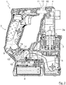
- Figur 2
- einen Schnitt durch das Gehäuse aus
Figur 1 ; - Figur 3
- eine perspektivische Ansicht eines Bewegungsbereichs zwischen einem Handgriff und einem Gehäusehauptteil des erfindungsgemäßen Gehäuses;
- Figur 4
- einen ersten Schnitt durch den in
Figur 3 dargestellten Bereich; und - Figur 5
- einen zweiten Schnitt durch den in
Figur 3 dargestellten Bereich. -
Figur 1 zeigt eine Seitenansicht eines Elektrohandwerkzeuggeräts 1, im vorliegenden Fall einer Bohrmaschine bzw. eines Bohrhammers. Das Elektrohandwerkzeuggerät 1 weist ein Gehäuse 2 auf, in dem die wesentlichen Komponenten des Elektrohandwerkzeuggeräts 1 untergebracht sind. Im vorliegenden Fall sind innerhalb des Gehäuses 2, jeweils mittels gestrichelter Linien dargestellt, eine Antriebseinrichtung 3, ein Getriebe 4 und eine Steuerungselektronik 5 angeordnet. Die Antriebseinrichtung 3, die beispielsweise als Elektromotor ausgebildet sein kann, dient zum Antrieb eines Werkzeugs 6, das in einem Spannfutter 7 des Elektrohandwerkzeuggeräts 1 aufgenommen ist. Zur Stromversorgung der Antriebseinrichtung 3 und der Steuerungselektronik 5 dient ein Akku 8, der in an sich bekannter Weise mit dem Gehäuse 2 verbunden sein kann. - In das Getriebe 4 kann ein sogenanntes Schlagwerk integriert sein, wie dies bei Schlagbohrmaschinen bzw. Bohrhämmern üblich ist. Durch das Schlagwerk werden Vibrationen in das Gehäuse 2 des Elektrohandwerkzeuggeräts 1 eingeleitet, die für einen Benutzer desselben unangenehm sein können. Um diese Vibrationen so gut wie möglich zu mindern bzw. zu dämpfen, ist das Gehäuse 2, wie nachfolgend beschrieben, ausgeführt.
- Das Gehäuse 2 weist ein Gehäusehauptteil 2a auf, in dem unter anderem die Antriebseinrichtung 3, das Getriebe 4 und die Steuerungselektronik 5 untergebracht sind. An dem Getriebe 4 ist das Spannfutter 7 angebracht. Des Weiteren weist das Gehäuse 2 einen Handgriff 9 auf, der in einem Verbindungsbereich 10 fest mit dem Gehäusehauptteil 2a verbunden ist. Im vorliegenden Fall geht das Gehäusehauptteil 2a in dem Verbindungsbereich 10 direkt in den Handgriff 9 über. Der Handgriff 9 und das Gehäusehauptteil 2a sind demnach zusammenhängende Bauteile. Bei der Herstellung des Gehäuses 2 werden der Handgriff 9 und das Gehäusehauptteil 2a beispielsweise durch Spritzgießen in einem Arbeitsgang hergestellt. In einem von dem Verbindungsbereich 10 beabstandeten Bereich, der nachfolgend als Bewegungsbereich 11 bezeichnet wird, ist zwischen dem Handgriff 9 und dem Gehäusehauptteil 2a ein Zwischenraum 12 vorgesehen. Dadurch kann sich der Handgriff 9 in diesem Bewegungsbereich 11 relativ zu dem Gehäusehauptteil 2a bewegen. Solche Bewegungen des Handgriffs 9 gegenüber dem Gehäusehauptteil 2a können sich durch die Vibrationen ergeben, die über den Verbindungsbereich 10 von dem Gehäusehauptteil 2a in den Handgriff 9 eingeleitet werden. Im Prinzip handelt es sich bei der Anordnung des Handgriffs 9 gegenüber dem Gehäusehauptteil 2a in dem Bewegungsbereich 11 um ein Loslager. Die Form des Handgriffs 9 entspricht der allgemeinen Form eines sogenannten D-Handgriffs, wobei im Gegensatz zu bekannten Lösungen der Zwischenraum 12 zwischen dem Handgriff 9 und dem Gehäusehauptteil 2a vorhanden ist. Trotz des Vorhandenseins des Zwischenraums 12, der sich im vorliegenden Fall im oberen Bereich des Gehäusehauptteils 2a befindet, ist der Handgriff 9, wie oben beschrieben, einteilig mit dem Gehäusehauptteil 2a verbunden.
- In einem Bereich zwischen dem Verbindungsbereich 10 und dem Bewegungsbereich 11 weist der Handgriff 9 eine Ausnehmung 13 auf, in die ein Dämpfungselement 14 eingesetzt ist, das eine größere Elastizität als das Material des Gehäusehauptteils 2a aufweist. Durch die Ausnehmung 13, die im vorliegenden Fall als in den Handgriff 9 ragender Schlitz in einer Außenwandung des Handgriffs 9 ausgebildet ist, wird der Querschnitt des Handgriffs 9 in diesem Bereich stark verringert, so dass sich der Handgriff 9 in diesem Bereich verformen kann, was die oben beschriebenen Bewegungen des Handgriffs 9 gegenüber dem Gehäusehauptteil 2a ermöglicht. Diese Verformungen werden durch das Dämpfungselement 14 annähernd nicht gehemmt. Vielmehr kann sich das Dämpfungselement 14 durch seine hohe Elastizität ebenso verformen und bildet lediglich eine geschlossene Außenkontur des Handgriffs 9. Im vorliegenden Fall beträgt die Tiefe der Ausnehmung 12 ungefähr die Hälfte der Breite des Handgriffs 9 in diesem Bereich und erstreckt sich in einer Richtung senkrecht zu der Zeichenebene durch den gesamten Handgriff 9.
- Das Dämpfungselement 14 kann beispielsweise aus einem Elastomer, insbesondere einem thermoplastischen Elastomer bestehen. Das Gehäusehauptteil 2a besteht im vorliegenden Fall aus einem geeigneten, harten Kunststoff, wie beispielsweise Polyamid. Der Handgriff 9 kann aus demselben Material bestehen wie das Gehäusehauptteil 2a. Selbstverständlich sind sowohl für das Gehäusehauptteil 2a und den Handgriff 9 als auch für das Dämpfungselement 14 andere Materialien denkbar. Das Dämpfungselement 14 kann mittels des an sich bekannten Verfahrens des Mehrkomponenten-Spritzgießens mit dem Gehäusehauptteil 2a verbunden werden. Die Ausnehmung 13 weist hierzu im vorliegenden Fall zwei seitliche Erweiterungen auf, in die das Material des Dämpfungselements 14 bei dem Mehrkomponenten-Spritzgießvorgang einströmen kann, so dass sich das Dämpfungselement 14 mit dem Handgriff 9 verklammert.
- Die Ausnehmung 13 mit dem darin angeordneten Dämpfungselement 14 wirkt dabei wie ein Gelenk, um das die Verformung des Handgriffs 9 stattfinden kann. Dabei wird die federnde Wirkung, die sich durch die Wahl des Materials des Handgriffs 9 ergibt, genutzt. Um die sich durch die Ausnehmung 13 ergebende Verformbarkeit des Handgriffs 9 zu maximieren, ist die Ausnehmung 13 im vorliegenden Fall auf der diametral gegenüberliegenden Seite des Bewegungsbereichs 11 angeordnet. Grundsätzlich wären jedoch auch andere Stellen zur Unterbringung der Ausnehmung 13 mit dem darin angeordneten Dämpfungselement 14 denkbar.
- Wie in den
Figuren 1 und2 zu erkennen ist, weist das Dämpfungselement 14 wenigstens eine, im vorliegenden Fall eine Vielzahl an inneren Ausnehmungen 15 auf. Die Ausnehmungen 15 sind vorzugsweise nicht gefüllt, d. h. es befindet sich Luft in den Ausnehmungen 15. Durch die inneren Ausnehmungen 15 und die Stege, die zwischen den inneren Ausnehmungen 15 verbleiben, kann die Flexibilität bzw. Elastizität des Dämpfungselements 14 eingestellt werden. Beispielsweise wird die Elastizität des Dämpfungselements 14 durch eine Vergrößerung der inneren Ausnehmungen 15 und/oder eine Verkleinerung der Stege verringert bzw. durch eine Verkleinerung der inneren Ausnehmungen 15 und/oder eine Vergrößerung der Stege erhöht. Zur Erhöhung der Elastizität des Dämpfungselements 14 kann außerdem auch ein weicherer Werkstoff für dasselbe verwendet werden. Das Dämpfungselement 14 ist im dargestellten Ausführungsbeispiel in Form einer Wabenstruktur ausgeführt. Gegebenenfalls könnte jedoch auch eine deutlich geringere Anzahl an inneren Ausnehmung 15 bzw. lediglich eine innere Ausnehmung 15 vorgesehen sein. - In den
Figuren 3, 4 und 5 ist die Ausführung des Bewegungsbereichs 11 zwischen dem Gehäusehauptteil 2a und dem Handgriff 9 deutlicher dargestellt. Dabei ist zu erkennen, dass das Gehäusehauptteil 2a in dem Bewegungsbereich 11 mittels eines mit dem Gehäusehauptteil 2a verbundenen Verbindungsstegs 16 beweglich gegenüber dem Handgriff 9 gelagert ist. Der Verbindungssteg 16 ist dabei, wie insbesondere inFigur 4 zu erkennen ist, in einer Führung 17 des Handgriffs 9 beweglich gelagert und in seitlicher Richtung geführt. Dies wird dadurch erreicht, dass der Verbindungssteg 16 an seiner dem Gehäusehauptteil 2a abgewandten Seite eine Verbreiterung 16a aufweist, und dass die Breite der Führung 17 in diesem Bereich geringfügig größer ist als die Breite der Verbreiterung 16a. Des Weiteren weist der Handgriff 9 ein Anschlagelement 18 auf, das die Bewegung des Verbindungsstegs 16 gegenüber dem Handgriff 9 begrenzt. Das Anschlagelement 18 ist durch die Führung 17 gebildet und erzeugt in beiden möglichen, mit "x" bezeichneten Bewegungsrichtungen des Verbindungsstegs 16 einen Anschlag für die Bewegungen des Handgriffs 9. Auf diese Weise ergibt sich eine Wegbegrenzung für die Bewegung des Handgriffs 9 gegenüber dem Gehäusehauptteil 2a in beiden Richtungen. Des Weiteren werden durch die Ausgestaltung der Führung 17 seitliche Bewegungen des Handgriffs 9 vermieden. Der Verbindungssteg 16 kann beispielsweise aus Aluminium bestehen und mit einem Teil des Getriebes 4, das in dem Gehäusehauptteil 2a angeordnet ist, verbunden sein. Wie inFigur 5 zu erkennen ist, ist der Zwischenraum 12, der in dem Bewegungsbereich 11 vorgesehen ist, mittels eines Faltenbalgs 19 abgedeckt.
Claims (10)
- Gehäuse (2) für ein Elektrohandwerkzeuggerät (1) mit einem Gehäusehauptteil (2a) und mit einem mit dem Gehäusehauptteil (2a) in einem Verbindungsbereich (10) fest verbundenen Handgriff (9), wobei in einem von dem Verbindungsbereich (10) beabstandeten Bewegungsbereich (11) ein Zwischenraum (12) zwischen dem Handgriff (9) und dem Gehäusehauptteil (2a) vorgesehen ist,
dadurch gekennzeichnet, dass der Handgriff (9) in einem Bereich zwischen dem Verbindungsbereich (10) und dem Bewegungsbereich (11) eine Ausnehmung (13) aufweist, in die ein Dämpfungselement (14) eingesetzt ist, das eine größere Elastizität als das Material des Gehäusehauptteils (2a) aufweist. - Gehäuse nach Anspruch 1,
dadurch gekennzeichnet, dass die Ausnehmung (13) auf der diametral gegenüberliegenden Seite des Bewegungsbereichs (11) angeordnet ist. - Gehäuse nach Anspruch 1 oder 2,
dadurch gekennzeichnet, dass das Dämpfungselement (14) aus einem Elastomer, insbesondere einem thermoplastischen Elastomer, besteht. - Gehäuse nach Anspruch 1, 2 oder 3,
dadurch gekennzeichnet, dass das Dämpfungselement (14) wenigstens eine innere Ausnehmung (15) aufweist. - Gehäuse nach einem der Ansprüche 1 bis 4,
dadurch gekennzeichnet, dass die Ausnehmung (13) des Handgriffs (9) als in den Handgriff (9) ragender Schlitz in einer Außenwandung des Handgriffs (9) ausgebildet ist. - Gehäuse nach einem der Ansprüche 1 bis 5,
dadurch gekennzeichnet, dass das Dämpfungselement (14) mittels Mehrkomponenten-Spritzgießen mit dem Gehäusehauptteil (2a) verbunden ist. - Gehäuse nach einem der Ansprüche 1 bis 6,
dadurch gekennzeichnet, dass das Gehäusehauptteil (2a) in dem Bewegungsbereich (11) mittels eines mit dem Gehäusehauptteil (2a) verbundenen Verbindungsstegs (10) beweglich gegenüber dem Handgriff (9) gelagert ist. - Gehäuse nach Anspruch 7,
dadurch gekennzeichnet, dass der Verbindungssteg (16) in einer Führung (17) des Handgriffs (9) beweglich gelagert und in seitlicher Richtung geführt ist, und dass der Handgriff (9) wenigstens ein Anschlagelement (18) zur Begrenzung der Bewegung des Verbindungsstegs (16) gegenüber dem Handgriff (9) aufweist. - Elektrohandwerkzeuggerät (1) mit einem Gehäuse (2) nach einem der Ansprüche 1 bis 8.
- Elektrohandwerkzeuggerät nach Anspruch 9,
dadurch gekennzeichnet, es als Bohrmaschine, insbesondere als Bohrhammer, ausgebildet ist.
Applications Claiming Priority (1)
| Application Number | Priority Date | Filing Date | Title |
|---|---|---|---|
| DE102019121700.8A DE102019121700A1 (de) | 2019-08-12 | 2019-08-12 | Gehäuse für ein Elektrohandwerkzeuggerät |
Publications (2)
| Publication Number | Publication Date |
|---|---|
| EP3778131A1 true EP3778131A1 (de) | 2021-02-17 |
| EP3778131B1 EP3778131B1 (de) | 2024-04-03 |
Family
ID=72039415
Family Applications (1)
| Application Number | Title | Priority Date | Filing Date |
|---|---|---|---|
| EP20190270.7A Active EP3778131B1 (de) | 2019-08-12 | 2020-08-10 | Gehäuse für ein elektrohandwerkzeuggerät |
Country Status (2)
| Country | Link |
|---|---|
| EP (1) | EP3778131B1 (de) |
| DE (1) | DE102019121700A1 (de) |
Cited By (1)
| Publication number | Priority date | Publication date | Assignee | Title |
|---|---|---|---|---|
| US12257671B2 (en) | 2022-06-16 | 2025-03-25 | Milwaukee Electric Tool Corporation | Power tool with battery vibration mitigation |
Citations (7)
| Publication number | Priority date | Publication date | Assignee | Title |
|---|---|---|---|---|
| EP0928669A2 (de) * | 1998-01-13 | 1999-07-14 | Lord Corporation | Kraftbetriebenes Werkzeug und Vibrationsdämpfer dafür |
| EP1867442A2 (de) * | 2006-06-16 | 2007-12-19 | Hitachi Koki Co., Ltd. | Werkzeugmaschine |
| DE102006059348A1 (de) | 2006-12-15 | 2008-07-03 | Robert Bosch Gmbh | Handwerkzeugmaschine mit schwingungsentkoppeltem Handgriff |
| EP2119537A1 (de) * | 2008-05-17 | 2009-11-18 | Metabowerke GmbH | Elektrohandwerkzeuggerät |
| EP2181810A1 (de) * | 2008-10-30 | 2010-05-05 | AEG Electric Tools GmbH | Vibrationsgedämpftes Elektrowerkzeug |
| EP2202034A1 (de) * | 2007-09-18 | 2010-06-30 | Makita Corporation | Tragbares arbeitswerkzeug |
| WO2011001979A1 (ja) * | 2009-07-02 | 2011-01-06 | 株式会社マキタ | 作業工具 |
Family Cites Families (4)
| Publication number | Priority date | Publication date | Assignee | Title |
|---|---|---|---|---|
| JPS5834271B2 (ja) * | 1980-07-18 | 1983-07-26 | 日立工機株式会社 | 振動工具のハンドル防振装置 |
| JPH08126975A (ja) * | 1994-10-28 | 1996-05-21 | Hitachi Koki Co Ltd | 電気ハンマの防振ハンドル |
| US9849577B2 (en) * | 2012-02-03 | 2017-12-26 | Milwaukee Electric Tool Corporation | Rotary hammer |
| JP6095460B2 (ja) * | 2013-04-17 | 2017-03-15 | 株式会社マキタ | ハンドルおよび動力工具 |
-
2019
- 2019-08-12 DE DE102019121700.8A patent/DE102019121700A1/de not_active Withdrawn
-
2020
- 2020-08-10 EP EP20190270.7A patent/EP3778131B1/de active Active
Patent Citations (7)
| Publication number | Priority date | Publication date | Assignee | Title |
|---|---|---|---|---|
| EP0928669A2 (de) * | 1998-01-13 | 1999-07-14 | Lord Corporation | Kraftbetriebenes Werkzeug und Vibrationsdämpfer dafür |
| EP1867442A2 (de) * | 2006-06-16 | 2007-12-19 | Hitachi Koki Co., Ltd. | Werkzeugmaschine |
| DE102006059348A1 (de) | 2006-12-15 | 2008-07-03 | Robert Bosch Gmbh | Handwerkzeugmaschine mit schwingungsentkoppeltem Handgriff |
| EP2202034A1 (de) * | 2007-09-18 | 2010-06-30 | Makita Corporation | Tragbares arbeitswerkzeug |
| EP2119537A1 (de) * | 2008-05-17 | 2009-11-18 | Metabowerke GmbH | Elektrohandwerkzeuggerät |
| EP2181810A1 (de) * | 2008-10-30 | 2010-05-05 | AEG Electric Tools GmbH | Vibrationsgedämpftes Elektrowerkzeug |
| WO2011001979A1 (ja) * | 2009-07-02 | 2011-01-06 | 株式会社マキタ | 作業工具 |
Cited By (1)
| Publication number | Priority date | Publication date | Assignee | Title |
|---|---|---|---|---|
| US12257671B2 (en) | 2022-06-16 | 2025-03-25 | Milwaukee Electric Tool Corporation | Power tool with battery vibration mitigation |
Also Published As
| Publication number | Publication date |
|---|---|
| EP3778131B1 (de) | 2024-04-03 |
| DE102019121700A1 (de) | 2021-02-18 |
Similar Documents
| Publication | Publication Date | Title |
|---|---|---|
| DE3121882C2 (de) | Vibrationswerkzeug mit einem vibrationsfesten Befestigungsmechanismus für den Handgriff | |
| EP0949988B1 (de) | Aufbruch- und/oder bohrhammer mit gegen das hammergehäuse abgefedertem handgriff | |
| DE102007022115B4 (de) | Handgeführte Motorsäge | |
| EP2305438B1 (de) | Arbeitsgerät | |
| DE102007048887A1 (de) | Handgeführtes Arbeitsgerät | |
| DE202014101503U1 (de) | Vorrichtung zur Bewegungsdämpfung | |
| WO2008034668A1 (de) | Elektrowerkzeugmaschine mit schwingungsentkoppeltem griffelement | |
| DE102005046407A1 (de) | Motorabdeckung | |
| DE102012108679A1 (de) | Flexible Schutzführung, die lange Elemente intern hält | |
| DE10347533B4 (de) | Lineare Führungsvorrichtung und Verfahren zur Montage derselben | |
| DE10035024A1 (de) | Hydraulisch dämpfendes Elastomerlager | |
| DE112016005460T5 (de) | Bewegungsführungsvorrichtung und Aktuator | |
| EP4331774A1 (de) | Werkzeugmaschine mit einer entkopplungsvorrichtung | |
| EP2050328A1 (de) | Handgeführtes Arbeitsgerät | |
| DE10236135B4 (de) | Tragbares, handgeführtes Werkzeug | |
| EP1691954B1 (de) | Aufbruch- und/oder bohrhammer mit linear geführter griffeinrichtung | |
| EP3778131B1 (de) | Gehäuse für ein elektrohandwerkzeuggerät | |
| DE102014008653B4 (de) | Stichsäge | |
| DE102009005549B4 (de) | Pneumatischer Lineargreifer | |
| DE102007012167A1 (de) | Drillelastisches und biegesteifes Stabelement zum Lagern und Führen einer beweglichen Klappe gegenüber einem Flügel eines Luftfahrzeugs | |
| WO2017140760A1 (de) | Dämpfung von schwingungen einer maschine | |
| EP2822734B1 (de) | Handwerkzeugmaschinenvorrichtung | |
| DE102015105181A1 (de) | Axialdämpfer | |
| DE10138123A1 (de) | Handwerkzeugmaschine mit vibrationsgedämpftem Handgriff | |
| EP1703168A2 (de) | Energieführungskette |
Legal Events
| Date | Code | Title | Description |
|---|---|---|---|
| PUAI | Public reference made under article 153(3) epc to a published international application that has entered the european phase |
Free format text: ORIGINAL CODE: 0009012 |
|
| STAA | Information on the status of an ep patent application or granted ep patent |
Free format text: STATUS: THE APPLICATION HAS BEEN PUBLISHED |
|
| AK | Designated contracting states |
Kind code of ref document: A1 Designated state(s): AL AT BE BG CH CY CZ DE DK EE ES FI FR GB GR HR HU IE IS IT LI LT LU LV MC MK MT NL NO PL PT RO RS SE SI SK SM TR |
|
| AX | Request for extension of the european patent |
Extension state: BA ME |
|
| STAA | Information on the status of an ep patent application or granted ep patent |
Free format text: STATUS: REQUEST FOR EXAMINATION WAS MADE |
|
| 17P | Request for examination filed |
Effective date: 20210319 |
|
| RBV | Designated contracting states (corrected) |
Designated state(s): AL AT BE BG CH CY CZ DE DK EE ES FI FR GB GR HR HU IE IS IT LI LT LU LV MC MK MT NL NO PL PT RO RS SE SI SK SM TR |
|
| STAA | Information on the status of an ep patent application or granted ep patent |
Free format text: STATUS: EXAMINATION IS IN PROGRESS |
|
| 17Q | First examination report despatched |
Effective date: 20221011 |
|
| GRAJ | Information related to disapproval of communication of intention to grant by the applicant or resumption of examination proceedings by the epo deleted |
Free format text: ORIGINAL CODE: EPIDOSDIGR1 |
|
| STAA | Information on the status of an ep patent application or granted ep patent |
Free format text: STATUS: GRANT OF PATENT IS INTENDED |
|
| GRAP | Despatch of communication of intention to grant a patent |
Free format text: ORIGINAL CODE: EPIDOSNIGR1 |
|
| INTG | Intention to grant announced |
Effective date: 20231121 |
|
| GRAS | Grant fee paid |
Free format text: ORIGINAL CODE: EPIDOSNIGR3 |
|
| GRAA | (expected) grant |
Free format text: ORIGINAL CODE: 0009210 |
|
| STAA | Information on the status of an ep patent application or granted ep patent |
Free format text: STATUS: THE PATENT HAS BEEN GRANTED |
|
| AK | Designated contracting states |
Kind code of ref document: B1 Designated state(s): AL AT BE BG CH CY CZ DE DK EE ES FI FR GB GR HR HU IE IS IT LI LT LU LV MC MK MT NL NO PL PT RO RS SE SI SK SM TR |
|
| REG | Reference to a national code |
Ref country code: CH Ref legal event code: EP |
|
| REG | Reference to a national code |
Ref country code: IE Ref legal event code: FG4D Free format text: LANGUAGE OF EP DOCUMENT: GERMAN |
|
| REG | Reference to a national code |
Ref country code: DE Ref legal event code: R096 Ref document number: 502020007518 Country of ref document: DE |
|
| REG | Reference to a national code |
Ref country code: LT Ref legal event code: MG9D |
|
| REG | Reference to a national code |
Ref country code: NL Ref legal event code: MP Effective date: 20240403 |
|
| PG25 | Lapsed in a contracting state [announced via postgrant information from national office to epo] |
Ref country code: NL Free format text: LAPSE BECAUSE OF FAILURE TO SUBMIT A TRANSLATION OF THE DESCRIPTION OR TO PAY THE FEE WITHIN THE PRESCRIBED TIME-LIMIT Effective date: 20240403 |
|
| PG25 | Lapsed in a contracting state [announced via postgrant information from national office to epo] |
Ref country code: NL Free format text: LAPSE BECAUSE OF FAILURE TO SUBMIT A TRANSLATION OF THE DESCRIPTION OR TO PAY THE FEE WITHIN THE PRESCRIBED TIME-LIMIT Effective date: 20240403 |
|
| PG25 | Lapsed in a contracting state [announced via postgrant information from national office to epo] |
Ref country code: IS Free format text: LAPSE BECAUSE OF FAILURE TO SUBMIT A TRANSLATION OF THE DESCRIPTION OR TO PAY THE FEE WITHIN THE PRESCRIBED TIME-LIMIT Effective date: 20240803 |
|
| PG25 | Lapsed in a contracting state [announced via postgrant information from national office to epo] |
Ref country code: BG Free format text: LAPSE BECAUSE OF FAILURE TO SUBMIT A TRANSLATION OF THE DESCRIPTION OR TO PAY THE FEE WITHIN THE PRESCRIBED TIME-LIMIT Effective date: 20240403 |
|
| PG25 | Lapsed in a contracting state [announced via postgrant information from national office to epo] |
Ref country code: FI Free format text: LAPSE BECAUSE OF FAILURE TO SUBMIT A TRANSLATION OF THE DESCRIPTION OR TO PAY THE FEE WITHIN THE PRESCRIBED TIME-LIMIT Effective date: 20240403 Ref country code: HR Free format text: LAPSE BECAUSE OF FAILURE TO SUBMIT A TRANSLATION OF THE DESCRIPTION OR TO PAY THE FEE WITHIN THE PRESCRIBED TIME-LIMIT Effective date: 20240403 |
|
| PG25 | Lapsed in a contracting state [announced via postgrant information from national office to epo] |
Ref country code: GR Free format text: LAPSE BECAUSE OF FAILURE TO SUBMIT A TRANSLATION OF THE DESCRIPTION OR TO PAY THE FEE WITHIN THE PRESCRIBED TIME-LIMIT Effective date: 20240704 |
|
| PG25 | Lapsed in a contracting state [announced via postgrant information from national office to epo] |
Ref country code: PT Free format text: LAPSE BECAUSE OF FAILURE TO SUBMIT A TRANSLATION OF THE DESCRIPTION OR TO PAY THE FEE WITHIN THE PRESCRIBED TIME-LIMIT Effective date: 20240805 |
|
| PG25 | Lapsed in a contracting state [announced via postgrant information from national office to epo] |
Ref country code: ES Free format text: LAPSE BECAUSE OF FAILURE TO SUBMIT A TRANSLATION OF THE DESCRIPTION OR TO PAY THE FEE WITHIN THE PRESCRIBED TIME-LIMIT Effective date: 20240403 |
|
| PG25 | Lapsed in a contracting state [announced via postgrant information from national office to epo] |
Ref country code: CZ Free format text: LAPSE BECAUSE OF FAILURE TO SUBMIT A TRANSLATION OF THE DESCRIPTION OR TO PAY THE FEE WITHIN THE PRESCRIBED TIME-LIMIT Effective date: 20240403 |
|
| PG25 | Lapsed in a contracting state [announced via postgrant information from national office to epo] |
Ref country code: PL Free format text: LAPSE BECAUSE OF FAILURE TO SUBMIT A TRANSLATION OF THE DESCRIPTION OR TO PAY THE FEE WITHIN THE PRESCRIBED TIME-LIMIT Effective date: 20240403 |
|
| PG25 | Lapsed in a contracting state [announced via postgrant information from national office to epo] |
Ref country code: LV Free format text: LAPSE BECAUSE OF FAILURE TO SUBMIT A TRANSLATION OF THE DESCRIPTION OR TO PAY THE FEE WITHIN THE PRESCRIBED TIME-LIMIT Effective date: 20240403 |
|
| PG25 | Lapsed in a contracting state [announced via postgrant information from national office to epo] |
Ref country code: PT Free format text: LAPSE BECAUSE OF FAILURE TO SUBMIT A TRANSLATION OF THE DESCRIPTION OR TO PAY THE FEE WITHIN THE PRESCRIBED TIME-LIMIT Effective date: 20240805 Ref country code: PL Free format text: LAPSE BECAUSE OF FAILURE TO SUBMIT A TRANSLATION OF THE DESCRIPTION OR TO PAY THE FEE WITHIN THE PRESCRIBED TIME-LIMIT Effective date: 20240403 Ref country code: NO Free format text: LAPSE BECAUSE OF FAILURE TO SUBMIT A TRANSLATION OF THE DESCRIPTION OR TO PAY THE FEE WITHIN THE PRESCRIBED TIME-LIMIT Effective date: 20240703 Ref country code: LV Free format text: LAPSE BECAUSE OF FAILURE TO SUBMIT A TRANSLATION OF THE DESCRIPTION OR TO PAY THE FEE WITHIN THE PRESCRIBED TIME-LIMIT Effective date: 20240403 Ref country code: IS Free format text: LAPSE BECAUSE OF FAILURE TO SUBMIT A TRANSLATION OF THE DESCRIPTION OR TO PAY THE FEE WITHIN THE PRESCRIBED TIME-LIMIT Effective date: 20240803 Ref country code: HR Free format text: LAPSE BECAUSE OF FAILURE TO SUBMIT A TRANSLATION OF THE DESCRIPTION OR TO PAY THE FEE WITHIN THE PRESCRIBED TIME-LIMIT Effective date: 20240403 Ref country code: GR Free format text: LAPSE BECAUSE OF FAILURE TO SUBMIT A TRANSLATION OF THE DESCRIPTION OR TO PAY THE FEE WITHIN THE PRESCRIBED TIME-LIMIT Effective date: 20240704 Ref country code: FI Free format text: LAPSE BECAUSE OF FAILURE TO SUBMIT A TRANSLATION OF THE DESCRIPTION OR TO PAY THE FEE WITHIN THE PRESCRIBED TIME-LIMIT Effective date: 20240403 Ref country code: ES Free format text: LAPSE BECAUSE OF FAILURE TO SUBMIT A TRANSLATION OF THE DESCRIPTION OR TO PAY THE FEE WITHIN THE PRESCRIBED TIME-LIMIT Effective date: 20240403 Ref country code: CZ Free format text: LAPSE BECAUSE OF FAILURE TO SUBMIT A TRANSLATION OF THE DESCRIPTION OR TO PAY THE FEE WITHIN THE PRESCRIBED TIME-LIMIT Effective date: 20240403 Ref country code: BG Free format text: LAPSE BECAUSE OF FAILURE TO SUBMIT A TRANSLATION OF THE DESCRIPTION OR TO PAY THE FEE WITHIN THE PRESCRIBED TIME-LIMIT Effective date: 20240403 Ref country code: RS Free format text: LAPSE BECAUSE OF FAILURE TO SUBMIT A TRANSLATION OF THE DESCRIPTION OR TO PAY THE FEE WITHIN THE PRESCRIBED TIME-LIMIT Effective date: 20240703 |
|
| REG | Reference to a national code |
Ref country code: DE Ref legal event code: R097 Ref document number: 502020007518 Country of ref document: DE |
|
| PG25 | Lapsed in a contracting state [announced via postgrant information from national office to epo] |
Ref country code: DK Free format text: LAPSE BECAUSE OF FAILURE TO SUBMIT A TRANSLATION OF THE DESCRIPTION OR TO PAY THE FEE WITHIN THE PRESCRIBED TIME-LIMIT Effective date: 20240403 |
|
| PG25 | Lapsed in a contracting state [announced via postgrant information from national office to epo] |
Ref country code: EE Free format text: LAPSE BECAUSE OF FAILURE TO SUBMIT A TRANSLATION OF THE DESCRIPTION OR TO PAY THE FEE WITHIN THE PRESCRIBED TIME-LIMIT Effective date: 20240403 |
|
| PG25 | Lapsed in a contracting state [announced via postgrant information from national office to epo] |
Ref country code: RO Free format text: LAPSE BECAUSE OF FAILURE TO SUBMIT A TRANSLATION OF THE DESCRIPTION OR TO PAY THE FEE WITHIN THE PRESCRIBED TIME-LIMIT Effective date: 20240403 Ref country code: SK Free format text: LAPSE BECAUSE OF FAILURE TO SUBMIT A TRANSLATION OF THE DESCRIPTION OR TO PAY THE FEE WITHIN THE PRESCRIBED TIME-LIMIT Effective date: 20240403 |
|
| PG25 | Lapsed in a contracting state [announced via postgrant information from national office to epo] |
Ref country code: SM Free format text: LAPSE BECAUSE OF FAILURE TO SUBMIT A TRANSLATION OF THE DESCRIPTION OR TO PAY THE FEE WITHIN THE PRESCRIBED TIME-LIMIT Effective date: 20240403 |
|
| PG25 | Lapsed in a contracting state [announced via postgrant information from national office to epo] |
Ref country code: SM Free format text: LAPSE BECAUSE OF FAILURE TO SUBMIT A TRANSLATION OF THE DESCRIPTION OR TO PAY THE FEE WITHIN THE PRESCRIBED TIME-LIMIT Effective date: 20240403 Ref country code: SK Free format text: LAPSE BECAUSE OF FAILURE TO SUBMIT A TRANSLATION OF THE DESCRIPTION OR TO PAY THE FEE WITHIN THE PRESCRIBED TIME-LIMIT Effective date: 20240403 Ref country code: RO Free format text: LAPSE BECAUSE OF FAILURE TO SUBMIT A TRANSLATION OF THE DESCRIPTION OR TO PAY THE FEE WITHIN THE PRESCRIBED TIME-LIMIT Effective date: 20240403 Ref country code: EE Free format text: LAPSE BECAUSE OF FAILURE TO SUBMIT A TRANSLATION OF THE DESCRIPTION OR TO PAY THE FEE WITHIN THE PRESCRIBED TIME-LIMIT Effective date: 20240403 Ref country code: DK Free format text: LAPSE BECAUSE OF FAILURE TO SUBMIT A TRANSLATION OF THE DESCRIPTION OR TO PAY THE FEE WITHIN THE PRESCRIBED TIME-LIMIT Effective date: 20240403 |
|
| PLBE | No opposition filed within time limit |
Free format text: ORIGINAL CODE: 0009261 |
|
| STAA | Information on the status of an ep patent application or granted ep patent |
Free format text: STATUS: NO OPPOSITION FILED WITHIN TIME LIMIT |
|
| 26N | No opposition filed |
Effective date: 20250106 |
|
| REG | Reference to a national code |
Ref country code: CH Ref legal event code: PL |
|
| PG25 | Lapsed in a contracting state [announced via postgrant information from national office to epo] |
Ref country code: LU Free format text: LAPSE BECAUSE OF NON-PAYMENT OF DUE FEES Effective date: 20240810 |
|
| GBPC | Gb: european patent ceased through non-payment of renewal fee |
Effective date: 20240810 |
|
| PG25 | Lapsed in a contracting state [announced via postgrant information from national office to epo] |
Ref country code: SI Free format text: LAPSE BECAUSE OF FAILURE TO SUBMIT A TRANSLATION OF THE DESCRIPTION OR TO PAY THE FEE WITHIN THE PRESCRIBED TIME-LIMIT Effective date: 20240403 Ref country code: CH Free format text: LAPSE BECAUSE OF NON-PAYMENT OF DUE FEES Effective date: 20240831 Ref country code: MC Free format text: LAPSE BECAUSE OF FAILURE TO SUBMIT A TRANSLATION OF THE DESCRIPTION OR TO PAY THE FEE WITHIN THE PRESCRIBED TIME-LIMIT Effective date: 20240403 |
|
| REG | Reference to a national code |
Ref country code: BE Ref legal event code: MM Effective date: 20240831 |
|
| PG25 | Lapsed in a contracting state [announced via postgrant information from national office to epo] |
Ref country code: GB Free format text: LAPSE BECAUSE OF NON-PAYMENT OF DUE FEES Effective date: 20240810 |
|
| PG25 | Lapsed in a contracting state [announced via postgrant information from national office to epo] |
Ref country code: BE Free format text: LAPSE BECAUSE OF NON-PAYMENT OF DUE FEES Effective date: 20240831 |
|
| PG25 | Lapsed in a contracting state [announced via postgrant information from national office to epo] |
Ref country code: IE Free format text: LAPSE BECAUSE OF NON-PAYMENT OF DUE FEES Effective date: 20240810 |
|
| PG25 | Lapsed in a contracting state [announced via postgrant information from national office to epo] |
Ref country code: SE Free format text: LAPSE BECAUSE OF FAILURE TO SUBMIT A TRANSLATION OF THE DESCRIPTION OR TO PAY THE FEE WITHIN THE PRESCRIBED TIME-LIMIT Effective date: 20240403 |
|
| PGFP | Annual fee paid to national office [announced via postgrant information from national office to epo] |
Ref country code: DE Payment date: 20250819 Year of fee payment: 6 |
|
| PGFP | Annual fee paid to national office [announced via postgrant information from national office to epo] |
Ref country code: FR Payment date: 20250821 Year of fee payment: 6 Ref country code: AT Payment date: 20251020 Year of fee payment: 5 |
|
| PG25 | Lapsed in a contracting state [announced via postgrant information from national office to epo] |
Ref country code: IT Free format text: LAPSE BECAUSE OF FAILURE TO SUBMIT A TRANSLATION OF THE DESCRIPTION OR TO PAY THE FEE WITHIN THE PRESCRIBED TIME-LIMIT Effective date: 20240403 Ref country code: CY Free format text: LAPSE BECAUSE OF FAILURE TO SUBMIT A TRANSLATION OF THE DESCRIPTION OR TO PAY THE FEE WITHIN THE PRESCRIBED TIME-LIMIT; INVALID AB INITIO Effective date: 20200810 |
|
| PG25 | Lapsed in a contracting state [announced via postgrant information from national office to epo] |
Ref country code: HU Free format text: LAPSE BECAUSE OF FAILURE TO SUBMIT A TRANSLATION OF THE DESCRIPTION OR TO PAY THE FEE WITHIN THE PRESCRIBED TIME-LIMIT; INVALID AB INITIO Effective date: 20200810 |