EP3777986B1 - Multi-dimensional building block toy building component and set capable of being built freely on front and back sides - Google Patents
Multi-dimensional building block toy building component and set capable of being built freely on front and back sides Download PDFInfo
- Publication number
- EP3777986B1 EP3777986B1 EP19785743.6A EP19785743A EP3777986B1 EP 3777986 B1 EP3777986 B1 EP 3777986B1 EP 19785743 A EP19785743 A EP 19785743A EP 3777986 B1 EP3777986 B1 EP 3777986B1
- Authority
- EP
- European Patent Office
- Prior art keywords
- module
- coupling
- coupling posts
- posts
- front side
- Prior art date
- Legal status (The legal status is an assumption and is not a legal conclusion. Google has not performed a legal analysis and makes no representation as to the accuracy of the status listed.)
- Active
Links
Images





Classifications
-
- A—HUMAN NECESSITIES
- A63—SPORTS; GAMES; AMUSEMENTS
- A63H—TOYS, e.g. TOPS, DOLLS, HOOPS OR BUILDING BLOCKS
- A63H33/00—Other toys
- A63H33/04—Building blocks, strips, or similar building parts
- A63H33/06—Building blocks, strips, or similar building parts to be assembled without the use of additional elements
- A63H33/08—Building blocks, strips, or similar building parts to be assembled without the use of additional elements provided with complementary holes, grooves, or protuberances, e.g. dovetails
- A63H33/086—Building blocks, strips, or similar building parts to be assembled without the use of additional elements provided with complementary holes, grooves, or protuberances, e.g. dovetails with primary projections fitting by friction in complementary spaces between secondary projections, e.g. sidewalls
-
- A—HUMAN NECESSITIES
- A63—SPORTS; GAMES; AMUSEMENTS
- A63H—TOYS, e.g. TOPS, DOLLS, HOOPS OR BUILDING BLOCKS
- A63H33/00—Other toys
- A63H33/04—Building blocks, strips, or similar building parts
- A63H33/06—Building blocks, strips, or similar building parts to be assembled without the use of additional elements
- A63H33/08—Building blocks, strips, or similar building parts to be assembled without the use of additional elements provided with complementary holes, grooves, or protuberances, e.g. dovetails
Definitions
- the present invention relates to the field of building block toy construction sets, and more particularly, to a multidimensional freely-buildable building block toy construction element and set.
- Building block toy is a toy for building a plurality of building blocks together to realize a creative idea of a builder.
- a module A is provided with a plurality of protruding coupling short posts h on a front side.
- the module A is provided with a concave surface on a back side; one or more protruding coupling short posts i are disposed on the concave surface; and a plurality of ribs are disposed on a side wall of the concave surface.
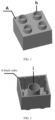
- FIG. 1 a module A is provided with a plurality of protruding coupling short posts h on a front side.
- the module A is provided with a concave surface on a back side; one or more protruding coupling short posts i are disposed on the concave surface; and a plurality of ribs are disposed on a side wall of the concave surface.
- a module B is provided with a plurality of protruding coupling short posts j on a front side; as shown in FIG. 4 , the module B is provided with a concave surface on a back side, and one or more protruding coupling short posts k are disposed on the concave surface.
- the building block building methods in the prior art are three: The building of the module A itself: the building blocks are built by coupling the coupling short posts h on the front side of the module A, the coupling short posts i on the back side, and the ribs on the side wall on the back side to form friction.
- the building between the front side of the module A and the back side of the module B the building blocks are built by coupling the coupling short posts k and the coupling short posts h to form friction.
- the building between the back side of the module A and the front side of the module B the building blocks are built by coupling the coupling short posts j of the module B and the ribs on the side wall on the back side of the module A to form friction.
- the methods have a lot of limitations; as shown in FIG. 5 and 6 , the sizes of the coupling posts on the front side of the module B and on the back side of the module A are inappropriate, and the coupling posts cannot be well coupled.
- CN 106 955 495 discloses a multidimensional front-and-back-sides-freely-buildable building block toy construction element according to the preamble of claim 1.
- the existing building block toy construction set can only provide three building methods, and cannot provide a building method for the building between the back side of the module A and the back side of the module B; furthermore, the method constrainedly provided for the building between the back side of the module A and the front side of the module B has a lot of limitations.
- using a building block toy construction set to build a multidimensional and multi-degree-of-freedom toy is greatly limited, and the creative idea of the builder cannot be freely realized.
- the object of the present invention is to provide a multidimensional front-and-back-sides-freely-buildable building block toy construction element and set, so as to ensure the degree of freedom in multidimensional building block building.
- the present invention provides a multidimensional front-and-back-sides-freely-buildable building block toy construction element according to claim 1.
- the present invention has the following advantages and beneficial effects: Apart from the building of a module C itself and the free building of conventional building blocks, the present invention provides freer building capability and building hand feeling in the following various building methods:
- the present invention provides a multidimensional front-and-back-sides-freely-buildable building block toy construction set, which improves the degree of freedom in building block building.
- FIG. 7 is a schematic view of the front side of the module C (first module) according to the present invention.
- the module C is provided with multiple columns of coupling short posts r; and the coupling short post r is a cylinder penetrating the module C, and is provided with the hole E in the middle.
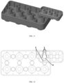
- FIG. 8 is a schematic view of the back side of the module C according to the present invention.
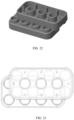
- the module C is provided with a concave surface; multiple columns of protruding coupling short posts t are disposed on the concave surface; and a plurality of ribs are disposed on a side wall of the concave surface.
- the distribution of the coupling short posts t on the back side of the module C is designed as follows: columns: uniformly distributed in the same columns as the coupling short posts r on the front side, and in the middle equally dividing two adjacent columns; rows: in the same columns as the coupling short posts r on the front side, each of the coupling short posts t is alternately arranged with the coupling short posts r, and is located in the middle equally dividing two coupling short posts r. Therefore, in such columns, the number of the coupling short posts t is one less than the number of the coupling short posts r.
- each coupling short post t is located at the middle position equally dividing two coupling short posts r in the same row. Therefore, in such columns, the number of the coupling short posts t is the same as the number of the coupling short posts r.
- FIG. 9 is a schematic view of the front side of the module D (second module). As shown in FIG. 9 , the module D is provided with multiple columns of coupling short posts s; and the coupling short post s is a cylinder penetrating the module D. The number of the coupling short posts s is the same as the number of the coupling short posts r of the module C.
- FIG. 10 is a schematic view of the back side of the module D according to the present invention.
- the module D is provided with a concave surface; the protruding coupling short posts u are disposed on the concave surface; and a plurality of ribs directly opposite to the coupling short posts u are disposed on the four side walls of the concave surface.
- the distribution of the coupling short posts u on the back side of the module D is designed as follows: columns: located in the middle equally dividing two adjacent columns of the coupling short posts s on the front side; rows: each coupling short post u is located in the middle equally dividing two coupling short posts s. Therefore, in each column, the number of the coupling short posts u is one less than the number of the coupling short posts s.
- the outer diameter of the first coupling short post r is a first size; the outer diameter of the second coupling short post t, the outer diameter of the third coupling short post s and the outer diameter of the fourth coupling short post u are all a second size; the module C and the module D are adapted to be inserted into each other.
- the first size is different from the second size. In another embodiment, the first size is greater than the second size.
- the nearest distance between the peripheries of two adjacent coupling short posts r on the front side of the module C is the second size.
- the nearest distance between the peripheries of two adjacent coupling short posts t located in the same row on the back side of the module C is the first size; and the nearest distance between the peripheries of two adjacent coupling short posts t located in the same column is the first size.
- the nearest distance between the peripheries of two diagonally adjacent third coupling short posts s on the front side of the module D is the second size; the nearest distance between the peripheries of two diagonally adjacent fourth coupling short posts u on the back side of the module D is the second size; and the front side of the module D is adapted to be inserted into the back side of another module D.
- the front side of the module D is also adapted to be inserted into the front side of another module D.
- FIG. 22 FIG. 23 are schematic views showing the coupling between the front side of the module D and the front side of another module D.
- the nearest distance between the peripheries of two coupling short posts s spaced apart by one third coupling short post s in the same row or column on the front side of the module D is the first size; and the front side of the module C is adapted to be inserted into the front side of the module D.
- the nearest distance between the peripheries of two coupling short posts u spaced apart by one fourth coupling short post u in the same row or column on the back side of the module D is the first size; and the front side of the module C is adapted to be inserted into the back side of the module D.
- the nearest distance between two second coupling short posts t in a diagonal direction on the back side of the module C is the second size; the back side of the module C is adapted to be inserted into the back side of the module D; and the back side of the module C is adapted to be inserted into the front side of the module D.
- a plurality of ribs are disposed on a side wall of the concave surface on the back side of the module C.
- a plurality of ribs are disposed on a side wall of the concave surface on the back side of the module D.
- the ribs on the back side of the module D are perpendicular to the side wall, and are arranged in rows or columns directly opposite to the fourth coupling short posts u.
- the width or length of the module C is two times that of the module D.
- the relationship between the outer diameter of the second coupling short post t, the outer diameter of the third coupling short post s and the outer diameter of the fourth coupling short post u and the width size of the module D is:
- the diameter d(r) of the first coupling short post r is equal to the distance f between circle centers of two adjacent second coupling short posts t minus d(t); and the distance f between the circle centers of two adjacent second coupling short posts t is the same as the width of the module D.
- the width of the module D is 20 mm; the thickness g of the side wall of the module D is 1.2 mm; the thickness h of the ribs on the side wall of the module D is 0.25 mm; and the outer diameter d(s) of the second coupling short post s equals the outer diameter d(t) of the third coupling short post t, equals the outer diameter d(u) of the fourth coupling short post u, and equals 7.1 mm.
- the actual diameter d(r) and the actual diameter d(s, t, u) will be slightly greater than 12.9 mm and 7.1 mm, respectively, for example, 0.01-0.10 mm greater than 12.9 mm and 7.1 mm, respectively.
- FIG. 11 is a schematic view showing the coupling between the back side of the module C and the front side of the module D.
- FIG. 12 schematically shows the coupling principle of the coupling relationship in FIG. 11 , which illustrates that the coupling succeeds owing to the designs of the coupling short posts r, s, t, and u on the module C and the module D.
- FIG. 13 is a schematic view showing the coupling between the back side of the module C and the front side of the module D at a randomly changed position.
- FIG. 14 schematically shows the coupling principle of the coupling relationship in FIG. 13 .
- the module D can be freely and successfully coupled to the module C whether they are coupled at any position, owing to the designs of the coupling short posts r, s, t, and u on the module C and the module D.
- FIG. 15 is a schematic view showing the coupling between the back side of the module C and the back side of the module D according to the present invention.
- FIG. 16 schematically shows the coupling principle of the coupling relationship in FIG. 15 .
- the coupling is free and succeeds owing to the designs of the coupling short posts r, s, t, and u on the module C and the module D.
- FIG. 17 is a schematic view showing the coupling between the front side of the module C and the front side of the module D according to the present invention.
- FIG. 18 schematically shows the coupling principle of the coupling relationship in FIG. 17 .
- the coupling is free and succeeds owing to the designs of the coupling short posts r, s, t, and u on the module C and the module D.
- FIG. 19 is a schematic view showing the coupling between the back side of the module C and the front side of the module L according to the present invention.
- the coupling is free and succeeds owing to the designs of the coupling short posts r and t on the front side and back side of the module C.
- the present invention provides freer building capability and building hand feeling in the following various building methods:
- FIG. 20 is a schematic view of the module K, and shows that the module K can be inserted in a through hole of the module C via the post head v.
- the post head v on the module K is in an interference fit with an inner hole of the coupling short post r.
- the diameter d(L) of the cruciform post head v is 10.8 mm
- the diameter d(E) of the inner hole of the inserted short post r is designed to be 10.7 mm
- the friction is provided by means of excess interference.
- the building block modules of the present invention are further smartly designed as follows:
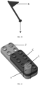
- the edges of the modules are all rounded corners; the coupling posts of the modules and the U-shaped rounded corners at the edge have the same center of circle; therefore, a plurality of unit modules C, J, and L can be built to form a uniform matched curved surface U, thereby obtaining a more comfortable hand feeling, and a more uniform appearance after building.
- the above introduction shows that in the present invention, by means of the smart structural design of the building block toy construction set, five free building modes, including the coupling between the front side of the module C and the back side of the module D, the coupling between the back side of the module C and the front side of the module D, the coupling between the back side of the module C and the back side of the module D, the coupling between the front side of the module C and the front side of the module D, and the coupling between the back side of the module C and the front side of the module L, are realized.
- the building of any components and modules are freer and safer, and provides a good hand feeling. It is easier to build different series and different designs of toys by using the building block toy construction set.
- the present invention has a uniform appearance and a comfortable hand feeling, and is easy to realize the creative idea of the builder, which has inestimable economic value.
Landscapes
- Toys (AREA)
Description
- The present invention relates to the field of building block toy construction sets, and more particularly, to a multidimensional freely-buildable building block toy construction element and set.
- Building block toy is a toy for building a plurality of building blocks together to realize a creative idea of a builder. In order to build diversified toys, generally a plurality of modules designed in different standards are provided, for example, as shown in
FIG. 1 , a module A is provided with a plurality of protruding coupling short posts h on a front side. As shown inFIG. 2 , the module A is provided with a concave surface on a back side; one or more protruding coupling short posts i are disposed on the concave surface; and a plurality of ribs are disposed on a side wall of the concave surface. As shown inFIG. 3 , a module B is provided with a plurality of protruding coupling short posts j on a front side; as shown inFIG. 4 , the module B is provided with a concave surface on a back side, and one or more protruding coupling short posts k are disposed on the concave surface. - The building block building methods in the prior art are three:
The building of the module A itself: the building blocks are built by coupling the coupling short posts h on the front side of the module A, the coupling short posts i on the back side, and the ribs on the side wall on the back side to form friction. - The building between the front side of the module A and the back side of the module B: the building blocks are built by coupling the coupling short posts k and the coupling short posts h to form friction.
- The building between the back side of the module A and the front side of the module B: the building blocks are built by coupling the coupling short posts j of the module B and the ribs on the side wall on the back side of the module A to form friction. The methods have a lot of limitations; as shown in
FIG. 5 and 6 , the sizes of the coupling posts on the front side of the module B and on the back side of the module A are inappropriate, and the coupling posts cannot be well coupled. -
CN 106 955 495 discloses a multidimensional front-and-back-sides-freely-buildable building block toy construction element according to the preamble of claim 1. - As described above, the existing building block toy construction set can only provide three building methods, and cannot provide a building method for the building between the back side of the module A and the back side of the module B; furthermore, the method constrainedly provided for the building between the back side of the module A and the front side of the module B has a lot of limitations. With the defects, using a building block toy construction set to build a multidimensional and multi-degree-of-freedom toy is greatly limited, and the creative idea of the builder cannot be freely realized.
- The object of the present invention is to provide a multidimensional front-and-back-sides-freely-buildable building block toy construction element and set, so as to ensure the degree of freedom in multidimensional building block building.
- The present invention provides a multidimensional front-and-back-sides-freely-buildable building block toy construction element according to claim 1.
- Beneficial effects:
Compared with the prior art, the present invention has the following advantages and beneficial effects:
Apart from the building of a module C itself and the free building of conventional building blocks, the present invention provides freer building capability and building hand feeling in the following various building methods: - I. The coupling between a front side of the module C and a back side of a module D: the coupling short posts r are coupled to the coupling short posts u and the side wall of the module D to generate friction. The deformation of the side wall is little, such method can better control coupling friction and experience hand feeling.
- II. The coupling between a back side of the module C and a front side of the module D: a side wall of the module C and the coupling short posts t are coupled to the coupling short posts s on the front side of the module D to generate friction. The design of the present invention can realize coupling at any place.
- III. The coupling between the back side of the module C and the back side of the module D: the coupling short posts s, t, and u have the same diameter; and therefore, the back side of the module C and the back side of the module D can be coupled and built at will.
- IV. The coupling between the front side of the module C and the front side of the module D: in the present invention, the coupling short posts s and u on the front side and back side of the module have the same diameter; therefore, besides that the back side of the module D can be coupled to the front side of the module C, the front side thereof can also be coupled to the front side of the module C at will; the feature will be more prominent especially when the module C is a very large flat board component (for example, 50CM*50CM) (
Fig. 17 and 18 ). - V. The coupling between the front side of the module D and the front side of the module D:
- VI. The coupling between the front side of the module D and the back side of the module D:
- VII. The coupling between the front side of the module C and the front side of the module C:
- VIII. The coupling between the back side of the module C and a front side of a module L: the module L is an implementation case of the module C, and is provided with only one coupling short post on the front side; furthermore, the diameter of the coupling short post is the same as r; therefore, the module L can be coupled to any position on the back side of the module C, thereby providing quite a lot of changes and design space.
- IX. The coupling short posts on the front side of the module C/D are not limited to 8; the figure in the document is only exemplary; the coupling short posts can be numerous such as 1, 2, 3...5...10...20...50... and the like, thereby providing imaginable building pleasure. Rounded corners at the edges of the modules are such designed that the coupling posts of the modules and the rounded corners at the edge have the same center of circle; a plurality of unit modules can be built to form a uniform matched curved surface, thereby having a more comfortable hand feeling; the built appearance is more uniform, freer, safer, and have better hand feeling; the modules are easier to build different series and different designs of toys, thereby realizing rich creative ideas of a builder.
- The present invention will be described in detail hereafter in combination with the drawings and specific embodiments.
-
FIG. 1 is a schematic view of the front side of the module A of the existing building block construction set; -
FIG. 2 is a schematic view of the back side of the module A of the existing building block construction set; -
FIG. 3 is a schematic view of the front side of the module B of the existing building block construction set; -
FIG. 4 is a schematic view of the back side of the module B of the existing building block construction set; -
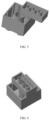
FIG. 5 is a schematic view showing the building between the back side of the module A and the front side of the module B; -
FIG. 6 is a schematic view showing the building between the back side of the module A and the front side of the module B; -
FIG. 7 is a schematic view of the front side of the module C (first module) according to the present invention; -
FIG. 8 is a schematic view of the back side of the module C according to the present invention; -
FIG. 9 is a schematic view of the front side of the module D (second module) according to the present invention; -
FIG. 10 is a schematic view of the back side of the module D according to the present invention; -
FIG. 11 is a schematic view showing the coupling between the back side of the module C and the front side of the module D according to the present invention; -
FIG. 12 schematically shows the coupling principle of the coupling relationship inFIG. 11 according to the present invention; -
FIG. 13 is a schematic view showing the coupling between the back side of the module C and the front side of the module D at a randomly changed position; -
FIG. 14 schematically shows the coupling principle of the coupling relationship inFIG. 13 ; -
FIG. 15 is a schematic view showing the coupling between the back side of the module C and the back side of the module D according to the present invention; -
FIG. 16 schematically shows the coupling principle of the coupling relationship inFIG. 15 ; -
FIG. 17 is a schematic view showing the coupling between the front side of the module C and the front side of the module D according to the present invention; -
FIG. 18 schematically shows the coupling principle of the coupling relationship inFIG. 17 ; -
FIG. 19 is a schematic view showing the coupling between the module C and the module L are coupled; -
FIG. 20 is a schematic view of a module K, and shows that the module k can be inserted in a through hole of the module C via a post head v; -
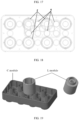
FIG. 21 shows that a plurality of unit modules C, L and J are built to form a uniform matched curved surface; -
FIG. 22 is a schematic view showing the coupling between the front sides of two modules D according to the present invention; and -
FIG. 23 is a schematic view of the size relationship between the short posts, the gap and the ribs when the front sides of two module D are coupled as shown inFIG. 22 . - The present invention provides a multidimensional front-and-back-sides-freely-buildable building block toy construction set, which improves the degree of freedom in building block building.
- In order to easily understand the measures, creative features, objectives to be achieved, and effects realized by the technology of the present invention, the present invention will be further described hereafter in combination with specific figures.
-
FIG. 7 is a schematic view of the front side of the module C (first module) according to the present invention. As shown inFIG. 7 , the module C is provided with multiple columns of coupling short posts r; and the coupling short post r is a cylinder penetrating the module C, and is provided with the hole E in the middle. -
FIG. 8 is a schematic view of the back side of the module C according to the present invention. As shown inFIG. 8 , the module C is provided with a concave surface; multiple columns of protruding coupling short posts t are disposed on the concave surface; and a plurality of ribs are disposed on a side wall of the concave surface. The distribution of the coupling short posts t on the back side of the module C is designed as follows: columns: uniformly distributed in the same columns as the coupling short posts r on the front side, and in the middle equally dividing two adjacent columns; rows: in the same columns as the coupling short posts r on the front side, each of the coupling short posts t is alternately arranged with the coupling short posts r, and is located in the middle equally dividing two coupling short posts r. Therefore, in such columns, the number of the coupling short posts t is one less than the number of the coupling short posts r. In the column located at the middle position equally dividing two adjacent columns of coupling short posts r, each coupling short post t is located at the middle position equally dividing two coupling short posts r in the same row. Therefore, in such columns, the number of the coupling short posts t is the same as the number of the coupling short posts r. -
FIG. 9 is a schematic view of the front side of the module D (second module). As shown inFIG. 9 , the module D is provided with multiple columns of coupling short posts s; and the coupling short post s is a cylinder penetrating the module D. The number of the coupling short posts s is the same as the number of the coupling short posts r of the module C. -
FIG. 10 is a schematic view of the back side of the module D according to the present invention. As shown inFIG. 10 , the module D is provided with a concave surface; the protruding coupling short posts u are disposed on the concave surface; and a plurality of ribs directly opposite to the coupling short posts u are disposed on the four side walls of the concave surface. The distribution of the coupling short posts u on the back side of the module D is designed as follows: columns: located in the middle equally dividing two adjacent columns of the coupling short posts s on the front side; rows: each coupling short post u is located in the middle equally dividing two coupling short posts s. Therefore, in each column, the number of the coupling short posts u is one less than the number of the coupling short posts s. - The outer diameter of the first coupling short post r is a first size; the outer diameter of the second coupling short post t, the outer diameter of the third coupling short post s and the outer diameter of the fourth coupling short post u are all a second size; the module C and the module D are adapted to be inserted into each other.
- In one embodiment of the present invention, the first size is different from the second size. In another embodiment, the first size is greater than the second size.
- In one embodiment of the present invention, the nearest distance between the peripheries of two adjacent coupling short posts r on the front side of the module C is the second size. The nearest distance between the peripheries of two adjacent coupling short posts t located in the same row on the back side of the module C is the first size; and the nearest distance between the peripheries of two adjacent coupling short posts t located in the same column is the first size. In this way, the modules can be inserted freely in the following insertion modes: the front side of the module C is inserted into the back side of another module C.
- In one embodiment of the present invention, the nearest distance between the peripheries of two diagonally adjacent third coupling short posts s on the front side of the module D is the second size; the nearest distance between the peripheries of two diagonally adjacent fourth coupling short posts u on the back side of the module D is the second size; and the front side of the module D is adapted to be inserted into the back side of another module D. In the present embodiment, the front side of the module D is also adapted to be inserted into the front side of another module D.
FIG. 22 FIG. 23 are schematic views showing the coupling between the front side of the module D and the front side of another module D. - In one embodiment of the present invention, the nearest distance between the peripheries of two coupling short posts s spaced apart by one third coupling short post s in the same row or column on the front side of the module D is the first size; and the front side of the module C is adapted to be inserted into the front side of the module D.
- In one embodiment of the present invention, the nearest distance between the peripheries of two coupling short posts u spaced apart by one fourth coupling short post u in the same row or column on the back side of the module D is the first size; and the front side of the module C is adapted to be inserted into the back side of the module D.
- In one embodiment of the present invention, the nearest distance between two second coupling short posts t in a diagonal direction on the back side of the module C is the second size; the back side of the module C is adapted to be inserted into the back side of the module D; and the back side of the module C is adapted to be inserted into the front side of the module D.
- In one embodiment of the present invention, a plurality of ribs are disposed on a side wall of the concave surface on the back side of the module C. A plurality of ribs are disposed on a side wall of the concave surface on the back side of the module D. The ribs on the back side of the module D are perpendicular to the side wall, and are arranged in rows or columns directly opposite to the fourth coupling short posts u.
- In one embodiment of the present invention, when the number of the first coupling short posts r on the front side of the module C is the same as the number of the rows or columns of the third coupling short posts s on the front side of the module D, the width or length of the module C is two times that of the module D.
- In one embodiment of the present invention, when the module D is provided with two third coupling short posts s in the same row, the relationship between the outer diameter of the second coupling short post t, the outer diameter of the third coupling short post s and the outer diameter of the fourth coupling short post u and the width size of the module D is:
- The outer diameter of the coupling short post is: d(t)=d(s)=d(u)=X/2-g*2-h*2;
- wherein X is the width of the module D; g is the thickness of the side wall of the module D; and h is the thickness of the ribs on the side wall of the module D.
- The diameter d(r) of the first coupling short post r is equal to the distance f between circle centers of two adjacent second coupling short posts t minus d(t); and the distance f between the circle centers of two adjacent second coupling short posts t is the same as the width of the module D.
- For example, the width of the module D is 20 mm; the thickness g of the side wall of the module D is 1.2 mm; the thickness h of the ribs on the side wall of the module D is 0.25 mm; and the outer diameter d(s) of the second coupling short post s equals the outer diameter d(t) of the third coupling short post t, equals the outer diameter d(u) of the fourth coupling short post u, and equals 7.1 mm.
- The diameter d(r) of the first coupling short post (r) is equal to the distance f between the circle centers of two adjacent second coupling short posts t minus d(t), i.e., 20-7.1=12.9 mm.
- During practical design, in order to generate friction, the actual diameter d(r) and the actual diameter d(s, t, u) will be slightly greater than 12.9 mm and 7.1 mm, respectively, for example, 0.01-0.10 mm greater than 12.9 mm and 7.1 mm, respectively.
- Such a smart design endows the present invention a multidimensional freely-buildable attribute.
FIG. 11 is a schematic view showing the coupling between the back side of the module C and the front side of the module D.FIG. 12 schematically shows the coupling principle of the coupling relationship inFIG. 11 , which illustrates that the coupling succeeds owing to the designs of the coupling short posts r, s, t, and u on the module C and the module D. -
FIG. 13 is a schematic view showing the coupling between the back side of the module C and the front side of the module D at a randomly changed position.FIG. 14 schematically shows the coupling principle of the coupling relationship inFIG. 13 . The module D can be freely and successfully coupled to the module C whether they are coupled at any position, owing to the designs of the coupling short posts r, s, t, and u on the module C and the module D. -
FIG. 15 is a schematic view showing the coupling between the back side of the module C and the back side of the module D according to the present invention.FIG. 16 schematically shows the coupling principle of the coupling relationship inFIG. 15 . The coupling is free and succeeds owing to the designs of the coupling short posts r, s, t, and u on the module C and the module D. -
FIG. 17 is a schematic view showing the coupling between the front side of the module C and the front side of the module D according to the present invention.FIG. 18 schematically shows the coupling principle of the coupling relationship inFIG. 17 . The coupling is free and succeeds owing to the designs of the coupling short posts r, s, t, and u on the module C and the module D. -
FIG. 19 is a schematic view showing the coupling between the back side of the module C and the front side of the module L according to the present invention. The coupling is free and succeeds owing to the designs of the coupling short posts r and t on the front side and back side of the module C. - It can be seen from the description above that, by using the multidimensional front-and-back-sides-freely-buildable building block toy construction set of the present invention, apart from the building of the module C itself and the free building of conventional building blocks, the present invention provides freer building capability and building hand feeling in the following various building methods:
- I. The coupling between the front side of the module C and the back side of the module D: the coupling short posts r are coupled to the coupling short posts u and the side wall of the module D to generate friction. Since the deformation of the side wall is small, such a method can better control the coupling friction and provide an experience with improved hand feeling.
- II. The coupling between the back side of the module C and the front side of the module D: the side wall of the module C and the coupling short posts t are coupled to the coupling short posts s on the front side of the module D to generate friction. The design of the present invention can realize coupling at any position.
- III. The coupling between the back side of the module C and the back side of the module D: the coupling short posts s, t, and u have the same diameter; and therefore, the back side of the module C and the back side of the module D can be coupled and built arbitrarily.
- IV. The coupling between the front side of the module C and the front side of the module D: as shown in
FIG. 17 and FIG. 18 , the coupling short posts s and u on the front side and back side of the module D have the same diameter; therefore, besides the coupling between the back side of the module D and the front side of the module C, the front side of the module D can also be coupled to the front side of the module C arbitrarily; and this feature will be more prominent especially when the module C is a very large flat board component (for example, with a size of 50 CM*50 CM). - V. The coupling between the back side of the module C and the front side of the module L: as shown in
FIG. 19 , the module L is an implementation case of the module C, and is provided with only one coupling short post on the front side; furthermore, the diameter of the coupling short post is the same as r; therefore, the module L can be coupled to any position on the back side of the module C, thereby providing a lot of space for changes and design. - VI. The number of the coupling short posts on the front side of the module C/D is not limited to 8; the figure in the present invention is only illustrative; and the coupling short posts can be numerous such as 1, 2, 3...5...10...20...50... and so on in number, thereby providing imaginable building pleasure.
- In addition, the present invention further provides some components having special structures for freely and stably building the modules.
FIG. 20 is a schematic view of the module K, and shows that the module K can be inserted in a through hole of the module C via the post head v. - The post head v on the module K is in an interference fit with an inner hole of the coupling short post r. For example, the diameter d(L) of the cruciform post head v is 10.8 mm; the diameter d(E) of the inner hole of the inserted short post r is designed to be 10.7 mm; and the friction is provided by means of excess interference.
- As shown in
FIG. 21 , in order to obtain a good building hand feeling and improve safety, the building block modules of the present invention are further smartly designed as follows:
The edges of the modules are all rounded corners; the coupling posts of the modules and the U-shaped rounded corners at the edge have the same center of circle; therefore, a plurality of unit modules C, J, and L can be built to form a uniform matched curved surface U, thereby obtaining a more comfortable hand feeling, and a more uniform appearance after building. - The above introduction shows that in the present invention, by means of the smart structural design of the building block toy construction set, five free building modes, including the coupling between the front side of the module C and the back side of the module D, the coupling between the back side of the module C and the front side of the module D, the coupling between the back side of the module C and the back side of the module D, the coupling between the front side of the module C and the front side of the module D, and the coupling between the back side of the module C and the front side of the module L, are realized. The building of any components and modules are freer and safer, and provides a good hand feeling. It is easier to build different series and different designs of toys by using the building block toy construction set. Furthermore, the present invention has a uniform appearance and a comfortable hand feeling, and is easy to realize the creative idea of the builder, which has inestimable economic value.
Claims (7)
- A multidimensional front-and-back-sides-freely-buildable building block toy construction element, comprising a second module (D);whereinthe second module is adapted to be coupled into a first module (C);a front side of the first module is provided with a plurality of first coupling posts (r), and a back side of the first module is provided with a plurality of second coupling posts (t);a front side of the second module is provided with a plurality of third coupling posts (s);each third coupling post (s) of the plurality of third coupling posts is a cylinder penetrating the second module;a back side of the second module is provided with a concave surface;a plurality of fourth coupling posts (u) are disposed on and protrude from the concave surface;the plurality of fourth coupling posts are distributed in columns located in a middle equally dividing two adjacent columns of the plurality of third coupling posts (s);each of the plurality of fourth coupling posts (u) is located in a middle equally dividing two third coupling posts (s) of the plurality of third coupling posts;an outer diameter of each first coupling post (r) of the plurality of first coupling posts is a first size;an outer diameter of each second coupling post (t) of the plurality of second coupling posts, an outer diameter of each third coupling post (s) of the plurality of third coupling posts and an outer diameter of each fourth coupling post (u) of the plurality of fourth coupling posts are all a second size, characterized in thata nearest distance between peripheries of two diagonally adjacent third coupling posts (s) of the plurality of third coupling posts on the front side of the second module is the second size;a nearest distance between peripheries of two diagonally adjacent fourth coupling posts (u) of the plurality of fourth coupling posts on the back side of the second module is the second size; andthe front side of the second module is adapted to be coupled into a back side of an adjacent second module; and a front side of the second module is adapted to be coupled into the front side of the adjacent second module.
- The multidimensional front-and-back-sides-freely-buildable building block toy construction element according to claim 1, whereinthe back side of the first module is provided with a concave surface; the plurality of second coupling posts (t) are disposed in columns on the concave surface and protrudes from the concave surface of the first module;the plurality of second coupling posts are uniformly distributed in the columns identical to columns of the plurality of first coupling posts (r), and in a middle equally dividing two adjacent columns of the columns of the plurality of first coupling posts;in the columns of the plurality of first coupling posts (r), each of the plurality of second coupling posts (t) is alternately arranged with the plurality of first coupling posts (r), and is located in a middle equally dividing two first coupling posts (r) of the plurality of first coupling posts;in a column located at the middle equally dividing the two adjacent columns of the plurality of first coupling posts (r), each of the plurality of second coupling posts (t) is located at a middle position equally dividing two first coupling posts (r) of the plurality of first coupling posts in one row; anda nearest distance between peripheries of two adjacent first coupling posts (r) of the plurality of first coupling posts on the front side of the first module is the second size.
- The multidimensional front-and-back-sides-freely-buildable building block toy construction element according to claim 2, whereina nearest distance between peripheries of two third coupling posts (s) spaced apart by one third coupling post (s) in one row or column on the front side of the second module is the first size or a nearest distance between peripheries of two fourth coupling posts (u) spaced apart by one fourth coupling post (u) in one row or column on the back side of the second module is the first size; andthe front side of the first module is adapted to be coupled into the front side of the second module.
- The multidimensional front-and-back-sides-freely-buildable building block toy construction element according to claim 2, whereina nearest distance between two second coupling posts (t) of the plurality of second coupling posts in a diagonal direction on the back side of the first module is the second size; andthe back side of the first module is adapted to be coupled into the back side of the second module; and the back side of the first module is adapted to be coupled into the front side of the second module.
- A multidimensional front-and-back-sides-freely-buildable building block toy construction set comprising the multidimensional front-and-back-sides-freely-buildable building block toy construction element according to claim 1 in combination with a multidimensional front-and-back-sides-freely-buildable building block toy construction element comprising a first module (C), whereina front side of the first module is provided with a plurality of first coupling posts (r), and a back side of the first module is provided with a concave surface;a plurality of second coupling posts (t) are disposed in columns on the concave surface and protrudes from the concave surface;the plurality of second coupling posts are uniformly distributed in the columns identical to columns of the plurality of first coupling posts (r), and in a middle equally dividing two adjacent columns of the columns of the plurality of first coupling posts;in the columns of the plurality of first coupling posts (r), the plurality of second coupling posts (t) are alternately arranged with the plurality of first coupling posts (r), and are located in a middle equally dividing two first coupling posts (r) of the plurality of first coupling posts;in a column located at the middle equally dividing the two adjacent columns of the plurality of first coupling posts (r), each of the plurality of second coupling posts (t) is located at a middle position equally dividing two first coupling posts (r) of the plurality of first coupling posts in one row;an outer diameter of each first coupling post (r) of the plurality of first coupling posts on the front side of the first module is a first size;a nearest distance between peripheries of two adjacent first coupling posts (r) of the plurality of first coupling posts on the front side is a second size;an outer diameter of each second coupling post (t) of the plurality of second coupling posts on the back side of the first module is the second size;a nearest distance between peripheries of two adjacent second coupling posts (t) in one row is the first size;a nearest distance between peripheries of two adjacent second coupling posts (t) in one column is the first size;the front side of the first module is adapted to be coupled into a back side of an adjacent first module; andthe first module is adapted to be coupled into the second module;a nearest distance between two second coupling posts (t) of the plurality of second coupling posts in a diagonal direction on the back side of the first module is the second size; andthe back side of the first module is adapted to be coupled into the back side of the second module; and the back side of the first module is adapted to be coupled into the front side of the second module.
- The multidimensional front-and-back-sides-freely-buildable building block toy construction set according to claim 5 wherein the first size is different from the second size.
- The multidimensional front-and-back-sides-freely-buildable building block toy construction set according to claim 6 wherein the first size is greater than the second size.
Applications Claiming Priority (3)
| Application Number | Priority Date | Filing Date | Title |
|---|---|---|---|
| CN201710227672.XA CN106955495A (en) | 2017-04-10 | 2017-04-10 | A kind of various dimensions, can the block toy building set freely built of positive and negative |
| CN201810313213.8A CN108325220B (en) | 2017-04-10 | 2018-04-09 | Multi-dimensional building block toy construction element capable of being freely built on front side and back side and kit |
| PCT/CN2019/078062 WO2019196591A1 (en) | 2017-04-10 | 2019-03-14 | Multi-dimensional building block toy building component and set capable of being built freely on front and back sides |
Publications (4)
| Publication Number | Publication Date |
|---|---|
| EP3777986A1 EP3777986A1 (en) | 2021-02-17 |
| EP3777986A4 EP3777986A4 (en) | 2021-09-29 |
| EP3777986C0 EP3777986C0 (en) | 2023-06-14 |
| EP3777986B1 true EP3777986B1 (en) | 2023-06-14 |
Family
ID=59484347
Family Applications (2)
| Application Number | Title | Priority Date | Filing Date |
|---|---|---|---|
| EP17905261.8A Active EP3608005B8 (en) | 2017-04-10 | 2017-09-12 | Multi-dimensional building block toy building set capable of being built freely on front and back sides |
| EP19785743.6A Active EP3777986B1 (en) | 2017-04-10 | 2019-03-14 | Multi-dimensional building block toy building component and set capable of being built freely on front and back sides |
Family Applications Before (1)
| Application Number | Title | Priority Date | Filing Date |
|---|---|---|---|
| EP17905261.8A Active EP3608005B8 (en) | 2017-04-10 | 2017-09-12 | Multi-dimensional building block toy building set capable of being built freely on front and back sides |
Country Status (7)
| Country | Link |
|---|---|
| US (2) | US10786748B2 (en) |
| EP (2) | EP3608005B8 (en) |
| JP (2) | JP7059305B2 (en) |
| KR (2) | KR102336502B1 (en) |
| CN (2) | CN106955495A (en) |
| DK (1) | DK3608005T3 (en) |
| WO (2) | WO2018188263A1 (en) |
Families Citing this family (12)
| Publication number | Priority date | Publication date | Assignee | Title |
|---|---|---|---|---|
| CN106955495A (en) * | 2017-04-10 | 2017-07-18 | 上海葡萄纬度科技有限公司 | A kind of various dimensions, can the block toy building set freely built of positive and negative |
| CN107441734A (en) * | 2017-08-24 | 2017-12-08 | 上海葡萄纬度科技有限公司 | It is a kind of can the building blocks external member built of various dimensions |
| CN108704323A (en) * | 2018-07-25 | 2018-10-26 | 上海葡萄纬度科技有限公司 | Toy building sets |
| JP6616031B1 (en) * | 2019-02-27 | 2019-12-04 | 高原木材株式会社 | Block member set |
| USD940795S1 (en) * | 2020-01-22 | 2022-01-11 | Costas Sisamos | Snap-lock construction toy beam unit |
| USD959568S1 (en) * | 2020-07-03 | 2022-08-02 | Sangchul Gil | Brick for construction toys |
| USD982096S1 (en) * | 2020-08-17 | 2023-03-28 | Matthew Andersen | Building block |
| US20230311016A1 (en) * | 2022-03-31 | 2023-10-05 | Laltitude Llc | Toy construction kit and tile |
| US12678703B2 (en) * | 2022-04-15 | 2026-07-14 | Hyochan JUN | Block-type art kit |
| USD1098297S1 (en) * | 2023-12-20 | 2025-10-14 | Lego A/S | Interlocking tray toy brick with arched bottom |
| USD1105280S1 (en) * | 2023-12-20 | 2025-12-09 | Lego A/S | Interlocking tray toy brick with flat bottom |
| USD1080753S1 (en) * | 2024-02-26 | 2025-06-24 | Yongkang Hongle Industry And Trade Co., Ltd | Set of building blocks |
Family Cites Families (55)
| Publication number | Priority date | Publication date | Assignee | Title |
|---|---|---|---|---|
| BE460827A (en) * | ||||
| FR563746A (en) * | 1922-06-21 | 1923-12-12 | Constuctions Electr De Delle A | Rolling bearing |
| US3005282A (en) * | 1958-01-28 | 1961-10-24 | Interlego Ag | Toy building brick |
| FR1206687A (en) | 1958-01-28 | 1960-02-11 | element for construction toy | |
| DK107858C (en) * | 1960-07-06 | 1967-07-10 | Godtfred Kirk Christiansen | Toy building element. |
| DE1603573A1 (en) * | 1966-08-12 | 1970-06-04 | Erwin Seckelmann | Construction toys |
| JPS4521638Y1 (en) * | 1966-12-30 | 1970-08-28 | ||
| US3528192A (en) * | 1967-10-09 | 1970-09-15 | Kevin F Meates | Toy construction kit comprising integrable structural elements of different types |
| JPS4511321Y1 (en) * | 1967-11-18 | 1970-05-20 | ||
| NL160491C (en) * | 1967-11-29 | 1979-11-15 | Interlego Ag | TOY BUILDING BOX, INCLUDING ONE-SIDED OPEN BOX, TAP-FACED BUILDING ELEMENTS, AND DUAL DIMENSION BUILDING ELEMENT SUITABLE FOR USE IN SUCH A TOY BUILDING BOX. |
| JPS4942157Y1 (en) * | 1969-12-22 | 1974-11-18 | ||
| ES383688A1 (en) * | 1970-09-16 | 1973-06-01 | Arnau Pibet | Toy construction systems |
| JPS6020296U (en) * | 1983-07-19 | 1985-02-12 | エクシン−ラインズ・ブロス,ソシエダツド・アノニマ | Detachable construction toy |
| JPS6185296U (en) * | 1984-11-13 | 1986-06-04 | ||
| US4744780A (en) * | 1986-02-06 | 1988-05-17 | Tyco Industries, Inc. | Adapter block |
| US5683283A (en) * | 1994-03-18 | 1997-11-04 | Ideal Ideas, Inc. | Construction blocks for extended support structures |
| DK112194A (en) * | 1994-09-29 | 1996-03-30 | Lego As | Stacking block system |
| CA2176073A1 (en) * | 1995-06-26 | 1996-12-27 | Henry Hung Lai Chung | Construction toy support base |
| USD378838S (en) * | 1995-09-14 | 1997-04-15 | Interlego Ag | Toy building element |
| USD378837S (en) * | 1995-09-14 | 1997-04-15 | Interlego Ag | Toy building element |
| TW328526B (en) * | 1996-09-17 | 1998-03-21 | Interlego Ag | A toy building set |
| KR100537395B1 (en) | 1996-09-17 | 2005-12-21 | 레고 에이/에스 | A toy building set |
| TW436310B (en) * | 1999-01-15 | 2001-05-28 | Interlego Ag | A building element for a toy building set |
| TW443939B (en) * | 1999-08-27 | 2001-07-01 | Interlego Ag | A toy building set |
| DE20111071U1 (en) * | 2001-07-04 | 2001-11-15 | HJB Rolling Mill Technology GmbH, 75417 Mühlacker | Building block |
| JP2005342166A (en) | 2004-06-02 | 2005-12-15 | Sakamoto Co Ltd | Articles that can be connected to and removed from a plurality of articles in the form of a block toy, and miniature model articles that are structured to be detachable using convex portions or concave portions formed on the articles. |
| JP4516543B2 (en) | 2006-04-10 | 2010-08-04 | 不二プラスチック株式会社 | Connected block |
| US7347028B1 (en) * | 2007-03-07 | 2008-03-25 | Inspired Child, Inc. | Modular construction system utilizing versatile construction elements with multi-directional connective surfaces and releasable interconnect elements |
| US8690631B2 (en) * | 2008-09-12 | 2014-04-08 | Texas Instruments Incorporated | Toy building block with embedded integrated circuit |
| JP2010172568A (en) | 2009-01-30 | 2010-08-12 | Kawada Co Ltd | Block toy |
| US20100203796A1 (en) * | 2009-02-07 | 2010-08-12 | Beg Ajmal M M | Constructional building set comprising building elements for person with color vision deficiency, and such building elements |
| US20120071061A1 (en) * | 2010-09-18 | 2012-03-22 | Scott Smith | Toy building block |
| CA2806494C (en) * | 2010-10-21 | 2019-01-08 | Lego A/S | A toy building set |
| JP5698385B2 (en) | 2011-12-08 | 2015-04-08 | ジェッカ リミテッド | Building blocks and building block fixtures |
| CN202490448U (en) * | 2012-03-21 | 2012-10-17 | 郭伟伦 | Toy building block |
| US8771032B2 (en) * | 2012-03-23 | 2014-07-08 | Delsun Co., Ltd. | Block assembly |
| CN202637989U (en) * | 2012-04-12 | 2013-01-02 | 汕头市沛利玩具实业有限公司 | Square-shaped building block toy element |
| US20140011422A1 (en) * | 2012-07-06 | 2014-01-09 | David Samuel Channin | Element for a toy interlocking construction block set |
| US8905812B2 (en) * | 2013-02-11 | 2014-12-09 | Cheng Pai-Chen | Toy block |
| US9737826B2 (en) * | 2013-03-10 | 2017-08-22 | Pai-Chen Cheng | Pairing block set and toy block thereof |
| JP3185708U (en) | 2013-06-18 | 2013-08-29 | 貴史 伊藤 | Block toys |
| BR102013024049A2 (en) * | 2013-09-19 | 2015-11-24 | Vilma da Silva Araujo Baptista | security seal for functional block-shaped cover, and, security seal manufacturing process |
| CN104623908A (en) * | 2013-11-13 | 2015-05-20 | 张衡 | Inserting plastic building block |
| US9345981B1 (en) * | 2014-02-24 | 2016-05-24 | Hasbro, Inc. | Multidimensional alignment spacing for toy building elements |
| US20150314209A1 (en) * | 2014-04-30 | 2015-11-05 | Hasbro, Inc. | Transformation toy construction system |
| US20150321114A1 (en) * | 2014-05-07 | 2015-11-12 | Dixie Toys Llc | Method For Attaching Toys To Each Other Using Retrofitted Accessory |
| DE202015002996U1 (en) * | 2015-04-21 | 2015-06-22 | Joachim Peiler | Flat connectable game building blocks |
| CN105833541A (en) * | 2016-04-06 | 2016-08-10 | 苏州乐派特机器人有限公司 | Building block spliced structural unit |
| CN205586577U (en) | 2016-04-06 | 2016-09-21 | 苏州乐派特机器人有限公司 | Building blocks mosaic structure unit |
| US20180256997A1 (en) * | 2017-03-08 | 2018-09-13 | Dustin A. Barwald | Vertical and lateral stackable brick assembly |
| CN106955495A (en) * | 2017-04-10 | 2017-07-18 | 上海葡萄纬度科技有限公司 | A kind of various dimensions, can the block toy building set freely built of positive and negative |
| US20190022543A1 (en) * | 2017-07-20 | 2019-01-24 | Lec, Inc. | Toy block structure |
| US20190358558A1 (en) * | 2018-05-24 | 2019-11-28 | Brian's Toys Inc. | Toy Building Brick System |
| CN108704323A (en) * | 2018-07-25 | 2018-10-26 | 上海葡萄纬度科技有限公司 | Toy building sets |
| JP6616031B1 (en) * | 2019-02-27 | 2019-12-04 | 高原木材株式会社 | Block member set |
-
2017
- 2017-04-10 CN CN201710227672.XA patent/CN106955495A/en active Pending
- 2017-09-12 EP EP17905261.8A patent/EP3608005B8/en active Active
- 2017-09-12 WO PCT/CN2017/101443 patent/WO2018188263A1/en not_active Ceased
- 2017-09-12 KR KR1020197033131A patent/KR102336502B1/en active Active
- 2017-09-12 DK DK17905261.8T patent/DK3608005T3/en active
- 2017-09-12 JP JP2019555667A patent/JP7059305B2/en active Active
- 2017-09-12 US US16/604,456 patent/US10786748B2/en active Active
-
2018
- 2018-04-09 CN CN201810313213.8A patent/CN108325220B/en active Active
-
2019
- 2019-03-14 WO PCT/CN2019/078062 patent/WO2019196591A1/en not_active Ceased
- 2019-03-14 US US17/044,717 patent/US11273386B2/en active Active
- 2019-03-14 KR KR1020207032043A patent/KR102536665B1/en active Active
- 2019-03-14 EP EP19785743.6A patent/EP3777986B1/en active Active
- 2019-03-14 JP JP2020555162A patent/JP2021520874A/en active Pending
Also Published As
| Publication number | Publication date |
|---|---|
| WO2018188263A1 (en) | 2018-10-18 |
| JP2020516385A (en) | 2020-06-11 |
| US20200147509A1 (en) | 2020-05-14 |
| US10786748B2 (en) | 2020-09-29 |
| EP3777986C0 (en) | 2023-06-14 |
| EP3608005A1 (en) | 2020-02-12 |
| KR20200016212A (en) | 2020-02-14 |
| EP3777986A4 (en) | 2021-09-29 |
| DK3608005T3 (en) | 2021-11-01 |
| US11273386B2 (en) | 2022-03-15 |
| EP3608005B1 (en) | 2021-08-11 |
| CN108325220B (en) | 2020-04-17 |
| US20210205728A1 (en) | 2021-07-08 |
| CN108325220A (en) | 2018-07-27 |
| JP7059305B2 (en) | 2022-04-25 |
| CN106955495A (en) | 2017-07-18 |
| WO2019196591A1 (en) | 2019-10-17 |
| EP3608005B8 (en) | 2021-09-22 |
| KR102536665B1 (en) | 2023-05-24 |
| EP3608005A4 (en) | 2020-04-08 |
| JP2021520874A (en) | 2021-08-26 |
| EP3777986A1 (en) | 2021-02-17 |
| KR20210018213A (en) | 2021-02-17 |
| KR102336502B1 (en) | 2021-12-06 |
Similar Documents
| Publication | Publication Date | Title |
|---|---|---|
| US11273386B2 (en) | Multi-dimensional building block toy building component and set capable of being built freely on front and back sides | |
| DE1625370B2 (en) | Pluggable toy building block | |
| US20160263489A1 (en) | Multidimensional alignment spacing for toy building elements | |
| JP2020516385A5 (en) | ||
| US20230302379A1 (en) | Multiple piece wooden block assembly | |
| WO2018222542A1 (en) | Cube based building block system | |
| US20170173487A1 (en) | Modular Cube Building System | |
| US4901672A (en) | Animal containment structure | |
| EP3431160B1 (en) | Interlocking block | |
| JP6695212B2 (en) | Chair connecting blocks | |
| CN103818180A (en) | Composite picture | |
| CN205434988U (en) | Building blocks that can present different images | |
| KR20090007665A (en) | Prefabricated maze device for traveling robot | |
| JP3067954B2 (en) | Mask staggered grid and method of assembling it | |
| US20160263475A1 (en) | Multi-trench 3d magic ball | |
| CN203230697U (en) | Peripheral special hook fastening bolt | |
| CN203735757U (en) | Optionally combinable bookshelf | |
| CN216505630U (en) | Variable-angle punching combined die | |
| CN102949853A (en) | Manufacturing method of magnetic building block | |
| CN109847385A (en) | A kind of interlocking building block | |
| JP3189809U (en) | Magic square puzzle | |
| CN202179848U (en) | Two-color puzzle | |
| JP2001098667A (en) | Builtup material | |
| JPS628300Y2 (en) | ||
| KR20090121262A (en) | Multi-directional three-dimensional fitting method that connects the solid interior space made of sheet material to endure a lot of load without wall, jaw or protruding connection |
Legal Events
| Date | Code | Title | Description |
|---|---|---|---|
| STAA | Information on the status of an ep patent application or granted ep patent |
Free format text: STATUS: THE INTERNATIONAL PUBLICATION HAS BEEN MADE |
|
| PUAI | Public reference made under article 153(3) epc to a published international application that has entered the european phase |
Free format text: ORIGINAL CODE: 0009012 |
|
| STAA | Information on the status of an ep patent application or granted ep patent |
Free format text: STATUS: REQUEST FOR EXAMINATION WAS MADE |
|
| 17P | Request for examination filed |
Effective date: 20201109 |
|
| AK | Designated contracting states |
Kind code of ref document: A1 Designated state(s): AL AT BE BG CH CY CZ DE DK EE ES FI FR GB GR HR HU IE IS IT LI LT LU LV MC MK MT NL NO PL PT RO RS SE SI SK SM TR |
|
| AX | Request for extension of the european patent |
Extension state: BA ME |
|
| DAV | Request for validation of the european patent (deleted) | ||
| DAX | Request for extension of the european patent (deleted) | ||
| A4 | Supplementary search report drawn up and despatched |
Effective date: 20210826 |
|
| RIC1 | Information provided on ipc code assigned before grant |
Ipc: A63H 33/08 20060101AFI20210820BHEP |
|
| STAA | Information on the status of an ep patent application or granted ep patent |
Free format text: STATUS: EXAMINATION IS IN PROGRESS |
|
| 17Q | First examination report despatched |
Effective date: 20220602 |
|
| GRAP | Despatch of communication of intention to grant a patent |
Free format text: ORIGINAL CODE: EPIDOSNIGR1 |
|
| STAA | Information on the status of an ep patent application or granted ep patent |
Free format text: STATUS: GRANT OF PATENT IS INTENDED |
|
| INTG | Intention to grant announced |
Effective date: 20230104 |
|
| GRAS | Grant fee paid |
Free format text: ORIGINAL CODE: EPIDOSNIGR3 |
|
| GRAA | (expected) grant |
Free format text: ORIGINAL CODE: 0009210 |
|
| STAA | Information on the status of an ep patent application or granted ep patent |
Free format text: STATUS: THE PATENT HAS BEEN GRANTED |
|
| RAP3 | Party data changed (applicant data changed or rights of an application transferred) |
Owner name: SHANGHAI BLOCKS TECHNOLOGY GROUP CO., LTD. |
|
| AK | Designated contracting states |
Kind code of ref document: B1 Designated state(s): AL AT BE BG CH CY CZ DE DK EE ES FI FR GB GR HR HU IE IS IT LI LT LU LV MC MK MT NL NO PL PT RO RS SE SI SK SM TR |
|
| REG | Reference to a national code |
Ref country code: CH Ref legal event code: EP |
|
| REG | Reference to a national code |
Ref country code: DE Ref legal event code: R096 Ref document number: 602019031108 Country of ref document: DE |
|
| REG | Reference to a national code |
Ref country code: AT Ref legal event code: REF Ref document number: 1578808 Country of ref document: AT Kind code of ref document: T Effective date: 20230715 |
|
| U01 | Request for unitary effect filed |
Effective date: 20230710 |
|
| U07 | Unitary effect registered |
Designated state(s): AT BE BG DE DK EE FI FR IT LT LU LV MT NL PT SE SI Effective date: 20230720 |
|
| REG | Reference to a national code |
Ref country code: LT Ref legal event code: MG9D |
|
| PG25 | Lapsed in a contracting state [announced via postgrant information from national office to epo] |
Ref country code: NO Free format text: LAPSE BECAUSE OF FAILURE TO SUBMIT A TRANSLATION OF THE DESCRIPTION OR TO PAY THE FEE WITHIN THE PRESCRIBED TIME-LIMIT Effective date: 20230914 Ref country code: ES Free format text: LAPSE BECAUSE OF FAILURE TO SUBMIT A TRANSLATION OF THE DESCRIPTION OR TO PAY THE FEE WITHIN THE PRESCRIBED TIME-LIMIT Effective date: 20230614 |
|
| PG25 | Lapsed in a contracting state [announced via postgrant information from national office to epo] |
Ref country code: RS Free format text: LAPSE BECAUSE OF FAILURE TO SUBMIT A TRANSLATION OF THE DESCRIPTION OR TO PAY THE FEE WITHIN THE PRESCRIBED TIME-LIMIT Effective date: 20230614 Ref country code: HR Free format text: LAPSE BECAUSE OF FAILURE TO SUBMIT A TRANSLATION OF THE DESCRIPTION OR TO PAY THE FEE WITHIN THE PRESCRIBED TIME-LIMIT Effective date: 20230614 Ref country code: GR Free format text: LAPSE BECAUSE OF FAILURE TO SUBMIT A TRANSLATION OF THE DESCRIPTION OR TO PAY THE FEE WITHIN THE PRESCRIBED TIME-LIMIT Effective date: 20230915 |
|
| PG25 | Lapsed in a contracting state [announced via postgrant information from national office to epo] |
Ref country code: SK Free format text: LAPSE BECAUSE OF FAILURE TO SUBMIT A TRANSLATION OF THE DESCRIPTION OR TO PAY THE FEE WITHIN THE PRESCRIBED TIME-LIMIT Effective date: 20230614 |
|
| PG25 | Lapsed in a contracting state [announced via postgrant information from national office to epo] |
Ref country code: IS Free format text: LAPSE BECAUSE OF FAILURE TO SUBMIT A TRANSLATION OF THE DESCRIPTION OR TO PAY THE FEE WITHIN THE PRESCRIBED TIME-LIMIT Effective date: 20231014 |
|
| PG25 | Lapsed in a contracting state [announced via postgrant information from national office to epo] |
Ref country code: SM Free format text: LAPSE BECAUSE OF FAILURE TO SUBMIT A TRANSLATION OF THE DESCRIPTION OR TO PAY THE FEE WITHIN THE PRESCRIBED TIME-LIMIT Effective date: 20230614 Ref country code: SK Free format text: LAPSE BECAUSE OF FAILURE TO SUBMIT A TRANSLATION OF THE DESCRIPTION OR TO PAY THE FEE WITHIN THE PRESCRIBED TIME-LIMIT Effective date: 20230614 Ref country code: RO Free format text: LAPSE BECAUSE OF FAILURE TO SUBMIT A TRANSLATION OF THE DESCRIPTION OR TO PAY THE FEE WITHIN THE PRESCRIBED TIME-LIMIT Effective date: 20230614 Ref country code: IS Free format text: LAPSE BECAUSE OF FAILURE TO SUBMIT A TRANSLATION OF THE DESCRIPTION OR TO PAY THE FEE WITHIN THE PRESCRIBED TIME-LIMIT Effective date: 20231014 Ref country code: CZ Free format text: LAPSE BECAUSE OF FAILURE TO SUBMIT A TRANSLATION OF THE DESCRIPTION OR TO PAY THE FEE WITHIN THE PRESCRIBED TIME-LIMIT Effective date: 20230614 |
|
| PG25 | Lapsed in a contracting state [announced via postgrant information from national office to epo] |
Ref country code: PL Free format text: LAPSE BECAUSE OF FAILURE TO SUBMIT A TRANSLATION OF THE DESCRIPTION OR TO PAY THE FEE WITHIN THE PRESCRIBED TIME-LIMIT Effective date: 20230614 |
|
| REG | Reference to a national code |
Ref country code: DE Ref legal event code: R097 Ref document number: 602019031108 Country of ref document: DE |
|
| U20 | Renewal fee for the european patent with unitary effect paid |
Year of fee payment: 6 Effective date: 20240226 |
|
| U1N | Appointed representative for the unitary patent procedure changed after the registration of the unitary effect |
Representative=s name: BAYRAMOGLU ET AL.; TR |
|
| PLBE | No opposition filed within time limit |
Free format text: ORIGINAL CODE: 0009261 |
|
| STAA | Information on the status of an ep patent application or granted ep patent |
Free format text: STATUS: NO OPPOSITION FILED WITHIN TIME LIMIT |
|
| 26N | No opposition filed |
Effective date: 20240315 |
|
| REG | Reference to a national code |
Ref country code: CH Ref legal event code: PL |
|
| PG25 | Lapsed in a contracting state [announced via postgrant information from national office to epo] |
Ref country code: MC Free format text: LAPSE BECAUSE OF FAILURE TO SUBMIT A TRANSLATION OF THE DESCRIPTION OR TO PAY THE FEE WITHIN THE PRESCRIBED TIME-LIMIT Effective date: 20230614 |
|
| PG25 | Lapsed in a contracting state [announced via postgrant information from national office to epo] |
Ref country code: MC Free format text: LAPSE BECAUSE OF FAILURE TO SUBMIT A TRANSLATION OF THE DESCRIPTION OR TO PAY THE FEE WITHIN THE PRESCRIBED TIME-LIMIT Effective date: 20230614 |
|
| PG25 | Lapsed in a contracting state [announced via postgrant information from national office to epo] |
Ref country code: IE Free format text: LAPSE BECAUSE OF NON-PAYMENT OF DUE FEES Effective date: 20240314 |
|
| PG25 | Lapsed in a contracting state [announced via postgrant information from national office to epo] |
Ref country code: IE Free format text: LAPSE BECAUSE OF NON-PAYMENT OF DUE FEES Effective date: 20240314 Ref country code: CH Free format text: LAPSE BECAUSE OF NON-PAYMENT OF DUE FEES Effective date: 20240331 |
|
| U20 | Renewal fee for the european patent with unitary effect paid |
Year of fee payment: 7 Effective date: 20250225 |
|
| PG25 | Lapsed in a contracting state [announced via postgrant information from national office to epo] |
Ref country code: CY Free format text: LAPSE BECAUSE OF FAILURE TO SUBMIT A TRANSLATION OF THE DESCRIPTION OR TO PAY THE FEE WITHIN THE PRESCRIBED TIME-LIMIT; INVALID AB INITIO Effective date: 20190314 |
|
| PG25 | Lapsed in a contracting state [announced via postgrant information from national office to epo] |
Ref country code: HU Free format text: LAPSE BECAUSE OF FAILURE TO SUBMIT A TRANSLATION OF THE DESCRIPTION OR TO PAY THE FEE WITHIN THE PRESCRIBED TIME-LIMIT; INVALID AB INITIO Effective date: 20190314 |
|
| PG25 | Lapsed in a contracting state [announced via postgrant information from national office to epo] |
Ref country code: TR Free format text: LAPSE BECAUSE OF FAILURE TO SUBMIT A TRANSLATION OF THE DESCRIPTION OR TO PAY THE FEE WITHIN THE PRESCRIBED TIME-LIMIT Effective date: 20230614 |
|
| U20 | Renewal fee for the european patent with unitary effect paid |
Year of fee payment: 8 Effective date: 20260226 |
|
| PGFP | Annual fee paid to national office [announced via postgrant information from national office to epo] |
Ref country code: GB Payment date: 20260323 Year of fee payment: 8 |