EP3777129B1 - Luftbildsensor zur aufnahme von matrixbildern durch zeitliche verschiebung und multispektrale summation - Google Patents
Luftbildsensor zur aufnahme von matrixbildern durch zeitliche verschiebung und multispektrale summation Download PDFInfo
- Publication number
- EP3777129B1 EP3777129B1 EP19712233.6A EP19712233A EP3777129B1 EP 3777129 B1 EP3777129 B1 EP 3777129B1 EP 19712233 A EP19712233 A EP 19712233A EP 3777129 B1 EP3777129 B1 EP 3777129B1
- Authority
- EP
- European Patent Office
- Prior art keywords
- image
- matrix
- image sensor
- detecting
- sensor according
- Prior art date
- Legal status (The legal status is an assumption and is not a legal conclusion. Google has not performed a legal analysis and makes no representation as to the accuracy of the status listed.)
- Active
Links
- 239000011159 matrix material Substances 0.000 title claims description 76
- 230000002123 temporal effect Effects 0.000 title claims 2
- 238000001914 filtration Methods 0.000 claims description 47
- 230000003595 spectral effect Effects 0.000 claims description 38
- 230000005540 biological transmission Effects 0.000 claims description 27
- 230000003287 optical effect Effects 0.000 claims description 19
- 230000033001 locomotion Effects 0.000 claims description 15
- 239000013598 vector Substances 0.000 claims description 4
- 238000001514 detection method Methods 0.000 description 42
- 239000003086 colorant Substances 0.000 description 5
- 238000000034 method Methods 0.000 description 3
- 244000007853 Sarothamnus scoparius Species 0.000 description 2
- 238000006073 displacement reaction Methods 0.000 description 2
- 230000000694 effects Effects 0.000 description 2
- 230000004927 fusion Effects 0.000 description 2
- 238000003491 array Methods 0.000 description 1
- 238000012550 audit Methods 0.000 description 1
- 230000000903 blocking effect Effects 0.000 description 1
- 238000004364 calculation method Methods 0.000 description 1
- 230000000295 complement effect Effects 0.000 description 1
- 230000001419 dependent effect Effects 0.000 description 1
- 229940082150 encore Drugs 0.000 description 1
- 235000021183 entrée Nutrition 0.000 description 1
- 230000001747 exhibiting effect Effects 0.000 description 1
- 238000003384 imaging method Methods 0.000 description 1
- 230000010354 integration Effects 0.000 description 1
- 238000004519 manufacturing process Methods 0.000 description 1
- 244000045947 parasite Species 0.000 description 1
- 230000000737 periodic effect Effects 0.000 description 1
- 238000009877 rendering Methods 0.000 description 1
- 238000005070 sampling Methods 0.000 description 1
- 239000004065 semiconductor Substances 0.000 description 1
- 238000001228 spectrum Methods 0.000 description 1
Images


Classifications
-
- G—PHYSICS
- G01—MEASURING; TESTING
- G01J—MEASUREMENT OF INTENSITY, VELOCITY, SPECTRAL CONTENT, POLARISATION, PHASE OR PULSE CHARACTERISTICS OF INFRARED, VISIBLE OR ULTRAVIOLET LIGHT; COLORIMETRY; RADIATION PYROMETRY
- G01J3/00—Spectrometry; Spectrophotometry; Monochromators; Measuring colours
- G01J3/28—Investigating the spectrum
- G01J3/2803—Investigating the spectrum using photoelectric array detector
-
- G—PHYSICS
- G01—MEASURING; TESTING
- G01J—MEASUREMENT OF INTENSITY, VELOCITY, SPECTRAL CONTENT, POLARISATION, PHASE OR PULSE CHARACTERISTICS OF INFRARED, VISIBLE OR ULTRAVIOLET LIGHT; COLORIMETRY; RADIATION PYROMETRY
- G01J3/00—Spectrometry; Spectrophotometry; Monochromators; Measuring colours
- G01J3/28—Investigating the spectrum
- G01J3/30—Measuring the intensity of spectral lines directly on the spectrum itself
- G01J3/36—Investigating two or more bands of a spectrum by separate detectors
-
- H—ELECTRICITY
- H04—ELECTRIC COMMUNICATION TECHNIQUE
- H04N—PICTORIAL COMMUNICATION, e.g. TELEVISION
- H04N23/00—Cameras or camera modules comprising electronic image sensors; Control thereof
- H04N23/10—Cameras or camera modules comprising electronic image sensors; Control thereof for generating image signals from different wavelengths
-
- H—ELECTRICITY
- H04—ELECTRIC COMMUNICATION TECHNIQUE
- H04N—PICTORIAL COMMUNICATION, e.g. TELEVISION
- H04N25/00—Circuitry of solid-state image sensors [SSIS]; Control thereof
- H04N25/70—SSIS architectures; Circuits associated therewith
- H04N25/71—Charge-coupled device [CCD] sensors; Charge-transfer registers specially adapted for CCD sensors
- H04N25/711—Time delay and integration [TDI] registers; TDI shift registers
-
- H—ELECTRICITY
- H04—ELECTRIC COMMUNICATION TECHNIQUE
- H04N—PICTORIAL COMMUNICATION, e.g. TELEVISION
- H04N25/00—Circuitry of solid-state image sensors [SSIS]; Control thereof
- H04N25/70—SSIS architectures; Circuits associated therewith
- H04N25/76—Addressed sensors, e.g. MOS or CMOS sensors
- H04N25/768—Addressed sensors, e.g. MOS or CMOS sensors for time delay and integration [TDI]
-
- G—PHYSICS
- G01—MEASURING; TESTING
- G01J—MEASUREMENT OF INTENSITY, VELOCITY, SPECTRAL CONTENT, POLARISATION, PHASE OR PULSE CHARACTERISTICS OF INFRARED, VISIBLE OR ULTRAVIOLET LIGHT; COLORIMETRY; RADIATION PYROMETRY
- G01J3/00—Spectrometry; Spectrophotometry; Monochromators; Measuring colours
- G01J3/28—Investigating the spectrum
- G01J3/2803—Investigating the spectrum using photoelectric array detector
- G01J2003/2806—Array and filter array
Definitions
- the invention relates to imagers comprising matrix detectors.
- linear detectors When shooting, airborne or space instruments generally use linear detectors operating as a “comb” (or “Push Broom”). These detectors acquire an image line by line.
- linear detectors with time shift and summation (“Time Delay Integration”, TDI) are used to improve the signal-to-noise ratio.
- Push Broom detectors have special areas of application. Their development is therefore often specific and costly. It is therefore interesting to take an interest in matrix sensors which are more generic. These sensors also offer the advantage of producing “rigid” images, the rows of the matrix being acquired at the same instant. This feature gives the advantage of producing images whose geometry is well controlled, which facilitates many applications.
- panchromatic image and the multi-spectral image are acquired at resolutions that may be different, typically with a factor of 4 between the pitch of the ground pixel of the multi-spectral image and the pitch of the ground pixel of the panchromatic image ( C. Latry et al., “Restoration technique for Pleiades-HR panchromatic images”, Proc. Arch. Photogramm. Remote Sens., 39: 555-560, 2012 ).
- the fusion of the images is for example carried out by an image fusion ground processing.
- the color image of the scene to be observed is conventionally produced by spatial sampling of three colors: red, blue and green (RBG) using a filter.
- the Bayer filter US 1976/3971065
- the Sparce CFA filter ON Semiconductor, “Sparse Color Filter Pattern Overview”, Information Notice AND9180/D) are generally used.
- the Bayer filter is present on most of the color cameras of the trade.
- the Sparse CFA filter is a variant of the Bayer filter providing better rendering of dark images.
- Sensors fitted with a Bayer filter or Sparse CFA filter are used on low-cost observation satellites, because the sensor is integrated into a commercial camera, known as an off-the-shell camera. They make it possible to take instantaneous views (Snapshot) in two dimensions by blocking the movement of the satellite during image acquisition. Nevertheless, with these filters, it is necessary to perform a demosaicing or demosaicing step to create a colored image for each spectral band (blue, green, red and possibly panchromatic) transmitted by the filter. Moreover, the effective resolution of the images depends on the spectral band considered.
- demosaicing gives unsatisfactory results in this case.
- the demosaicing algorithm is therefore implemented on board, which requires additional calculation resources.
- the volume of images acquired is then greater, since it comprises three colors per pixel whereas a conventional solution comprises a panchromatic pixel and the color on multi-spectral pixels four times larger.
- the Bayer filter is limited to three colors, which does not always satisfy the needs of space observation missions which may require more than three spectral bands.
- CMOS sensor comprising a multi-spectral filter having several filtering colors making it possible to acquire color images.
- the document DE 3819828 discloses a particular optical arrangement comprising a prism for abutting two image sensors.
- the document EP 2150039 discloses a method of imaging objects in motion relative to each other.
- the invention aims to overcome the aforementioned drawbacks and limitations of the prior art. More specifically, it aims to provide an image sensor comprising time-shifting and summation detection arrays, enabling continuous TDI array shots, and a multi-spectral filter comprising multiple filter elements, requiring no on-board demosaicing processing and providing access to more than three spectral bands transmitted by the filtering elements.
- the image sensor comprises a reflecting prism placed between two detection matrices in the direction of movement of said wearer so that the two detection matrices are abutted along the lines of said detection matrices; more particularly it comprises at least a third detection matrix which is placed between said reflecting prism and one of the two first detection matrices in the direction of movement of said wearer, this third matrix being placed in height under said prism, so as to increase the number of spectral bands filtered by said multi-spectral filters placed in front of each of the detection matrices; and even more particularly it comprises at least one dichroic plate placed between said reflecting prism and said third detection matrix in the direction of movement of the wearer so as to minimize the optical field of said sensor.
- the signal processing circuit is a programmable digital circuit.
- the invention also relates to a spatial or airborne optical instrument for acquiring images, comprising an image sensor according to one embodiment of the invention.
- the figure 1 illustrates the principle of operation, according to the prior art ( US 2016/9357145 ), of a matrix image sensor CI comprising a matrix zone for detection by time shift for summation of rows, this matrix zone comprises at least one detection matrix M.
- the matrix detection zone comprises pixels PX, arranged by rows and by columns. The charges generated by these pixels are accumulated in the detection matrix M.
- the rows are numbered from 1 to N and the columns are numbered from 1 to MC.
- the carrier in which this sensor CI is embedded moves with a speed V in the direction perpendicular to the lines. Consequently, the image of the scene to be observed, formed on the detection matrix zone M by an optical system not shown, scrolls in the same direction, with the orientation opposite to V.
- the interval ⁇ t depends both on the desired spatial resolution (a function of the magnification of the optical system and the size of the pixels) and on the speed of movement V of the wearer relative to the ground.
- An electronic processing circuit CT adds the signals generated by the different lines of pixels PX of the matrix M and corresponding to the same line of the image.
- the circuit CT supplies image data vectors VD, each being representative of a line of the optical image, integrated over a time equal to N int ⁇ ⁇ t, N int being the number of lines added for obtain a line of the optical image.
- This summation of the signals makes it possible to increase the signal-to-noise ratio of the image data acquired by the sensor.
- the vectors VD form an image data matrix having NN int rows making it possible to obtain an optical image of the scene to be observed.
- the picture 2 illustrates the operating principle of an image sensor according to a first embodiment of the invention.
- a multi-spectral filter comprising several filtering elements is placed in front of the detection matrix M.
- the filtering elements are arranged in the form of rows and columns corresponding to the rows and columns of pixels of the detection matrix M. They are chosen from a plurality of filter element types characterized by respective transmission spectral bands whose union optionally determines a panchromatic spectral band of the filter.
- Each column of the multi-spectral filter comprises an alternation of filtering elements of different types, such that the union of their transmission spectral bands determines said panchromatic band of the filter.
- the filtering elements can be arranged in parallel horizontal bands B1, B2, ..., BM.
- the strips include at least two rows of filtering elements, which corresponds to a minimum height of three pixels.
- the filtering elements can for example be configured so as to have several spectral transmission bands within the same band or so as to have the same spectral transmission band within the same band.
- the processing circuit CT will output a data matrix MD comprising at most N+1-Lint rows, where Lint is the number of summations performed during the acquisition of an image, Lint being an integer less than or equal to N and greater than or equal to 2.
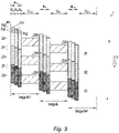
- the picture 3 illustrates more precisely the principle of operation of an image sensor according to a second embodiment of the invention. Only the detection matrix M is shown in this figure. For reasons of simplicity, only one column of the matrix M is represented, but the principle applies for each column of pixels of the matrix.
- the filtering elements of the filter are arranged in three horizontal and parallel bands B1, B2 and B3.
- the filtering elements of the same strip have the same spectral transmission band, which is different from the other spectral transmission bands of the filtering elements present on the other strips.
- An acquisition period ta therefore has the duration of the exposure phase te and of the read phase t1.
- This exposure phase is divided into several elementary exposures of a duration ⁇ te.
- the duration ⁇ te corresponds to the scrolling of the scene to be observed over a pixel.
- the signal detected on each pixel is stored then added electronically, after time shift, to the signals generated by other pixels, on the same scene at different instants.
- pixel PX3 detects a signal which is added by the processing circuit CT to the signal detected by the pixel PX2 at the second elementary exposure, then the sum is added by the circuit CT to the signal detected by the pixel PX1 at the third elementary exposure. The same is true for all the pixels constituting the detection matrix M.
- the elementary exposure number corresponds to the summation number of a signal detected on a given pixel of the scene to be observed.
- the typical number of summations, Lint is 20.
- This useful area is delimited by the first and the last line of pixels of the same band having been integrated as many times as the number of elementary exposures, and constitutes a data matrix, having a maximum number of lines equal to N+ 1-Lint, where N is the number of lines of pixels of the detection matrix and Lint is the number of elementary exposures made during the acquisition, this data matrix being supplied at the output of the processing circuit for this instant of acquisition.
- the heights of the useful zones ZU depend on the size of the detection matrix M, the number of bands and the height of the lost zones ZP.
- image K-1, image K, image K+1, ... so as to have an overlap zone ZR between two successive images.
- the images K-1, K, K+1, etc... are images obtained from the data matrices provided at the output of the processing circuit and having at most N+1-Lint rows, Lint being the number of elementary exposures for an instant of acquisition, that is to say the number of summations carried out during an instant of acquisition.
- the overlap zone ZR depends on the image frequency, i.e. the relative displacement of the matrix between an image K and an image K+1 along the horizontal direction representing time t (i.e.
- the slow motion of the carrier that is to say the relative displacement of the matrix between the images K and K+1 in the vertical direction representing the scrolling P, and the heights of the useful zones ZU.
- the slow motion of the carrier that is to say the relative displacement of the matrix between the images K and K+1 in the vertical direction representing the scrolling P, and the heights of the useful zones ZU.
- the filter advantageously comprises a band whose filtering elements have a panchromatic transmission spectral band.
- the multi-spectral filter is arranged on several detection matrices.
- the processing circuit CT is configured to carry out a coupled reading of the pixels (“binning” in English) belonging to the same column, called vertical pixels. This coupled reading is performed on the pixels exhibiting a multi-spectral filtering, that is to say a non-panchromatic filtering. It is also possible to configure the processing circuit CT to carry out a coupled reading of the pixels belonging to the same line, called horizontal pixels, having a multi-spectral filtering to reduce the video bit rate.
- the coupled reading of the horizontal and vertical pixels makes it possible to balance the signal-to-noise ratio of the panchromatic and multi-spectral channels, and thus reduce the amount of data to be stored. In addition, this allows a gain on the reading frequency of the rows of the matrix M, as well as on the video bit rate.
- the matrices are butted. Nevertheless, due to the dimensions of the boxes containing the detection matrices, the staggered abutment usually made for linear detectors is not always achievable, because the boxes can touch each other and this abutment can lead to a significant increase in the field of the focusing optics.
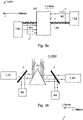
- the figures 4a to 5b present several embodiments of the invention for abutting the detection matrices and thus arranging the focal plane of the optical instrument comprising an image sensor according to the invention.
- the figures 4a and 4b present a first arrangement of the focal plane.
- Two matrices P_MS1 and P_MS2 are face to face in the running direction of the wearer, and offset in the direction of the swath (width of the shot).
- Matrix P_MS1 “sees” only part of matrix P_MS2, this part corresponding to zone ZR2 of the figure. This zone is called the overlap zone.
- a reflective prism PR is placed between the two matrices in the direction of travel, it thus allows abutment of the two matrices P_MS1 and P_MS2 in the direction of the swath, that is to say along the lines of the detection matrices.
- the field in the running direction of the carrier is thus minimized and this allows the abutment of the matrices in the fields following the running speed (ALT fields, "A Long Track”) or in the fields perpendicular to the running speed (ACT , “A Cross Track”).
- the figure 6a presents a fifth embodiment of the invention, in which the filtering elements of the filter are arranged so as to have a regular and periodic filtering pattern on the rows and columns of the filter, this pattern being called sub-pattern SM.
- the sub-pattern comprises an alternation of filter elements of different types, such that the union of their transmission spectral bands determines a panchromatic spectral band of the filter.
- the spectral transmission bands of the filtering elements of the sub-pattern are complementary in the spectrum.
- the filtering element for pixel 1 PX1 is dedicated to the blue spectral band, that of pixel 2 PX2 is dedicated to the green band, that of pixel 3 PX3 to that of red and that of pixel 4 PX4 to near infrared.
- the processing circuit CT is then configured to integrate the signals from the pixels so as to successively produce a multi-spectral image and a panchromatic image.
- the panchromatic image is produced by summing, on the same column, all the signals of the pixels belonging to several complete sub-patterns, while the multi-spectral image is produced by summing, on the same column, the signals pixels modulo the width of the subpattern. For example, for a sub-pattern 4 pixels wide, the panchromatic image will be obtained by summing over the same column the signals generated by the pixels PX1, PX2, PX3 and PX4, whereas the multi-spectral image will be obtained by summing on the same column the signals generated by the pixels PX1, PX5, PX9, etc ....
- panchromatic images at full resolution, as well as multi-spectral images sub-sampled according to the sub-pattern of the filter multi spectral.
- the alternation of panchromatic and multi-spectral images, associated with the overlap between two consecutive images according to the acquisition frequency of the sensor and the movement of the wearer, makes it possible to acquire the entire scene to be observed in all the spectral channels.
- panchromatic band image at full resolution and of optimal quality allows the use of PAN-sharpening type algorithms ( C. Latry et al., “Restoration technique for Pleiades-HR panchromatic images”, Proc. Int. Arch. Photogramm. Remote Sens., 39: 555-560, 2012 ) to generate full resolution colored images.
- the full resolution corresponds to the resolution of the detection matrix M alone, that is to say the resolution of the matrix M without taking into account the multi-spectral filter placed in front of this matrix.
- the number of summations carried out for the “TDI” effect is therefore dependent on the width of the sub-pattern.
- the presence of a filtering sub-pattern on the filter makes it possible to have a regular filtering pattern over the entire detection matrix, to have a variable number of spectral bands and not to dedicate an area of the matrix to the panchromatic spectral band.
- the panchromatic spectral band makes it possible to generate a full resolution image of good quality, but it is not useful as a real image product. It is therefore an equivalent loss of useful area at the level of the image sensor.
- the periodicity of the sub-pattern on the rows and columns of the detection matrix M makes it possible to reduce the Moiré effects during the reconstruction of the scene to be observed in colors. Nevertheless, it is possible to have a subpattern in which the filter elements are placed periodically only along the columns of the detection matrix M ( figure 6b ). This facilitates the summation of the signals generated by the pixels within the same column.
- the processing circuit CT is a programmable digital circuit.
- the figure 7 very schematically illustrates a SAT carrier, for example a spacecraft, and more particularly a satellite, equipped with an optical image acquisition instrument IO.
- This optical instrument IO comprises a conventional optical system SO, for example a telescope, coupled to an image sensor CI according to one embodiment of the invention.
Landscapes
- Engineering & Computer Science (AREA)
- Multimedia (AREA)
- Signal Processing (AREA)
- Physics & Mathematics (AREA)
- Spectroscopy & Molecular Physics (AREA)
- General Physics & Mathematics (AREA)
- Color Television Image Signal Generators (AREA)
- Transforming Light Signals Into Electric Signals (AREA)
- Image Processing (AREA)
Claims (15)
- Bildsensor (CI), konfiguriert zum Aufnehmen einer zu beobachtenden Szene, wenn sich der Sensor linear zu der Szene in einer Bewegungsrichtung p bewegt, wobei der Sensor Folgendes umfasst:- mindestens eine Matrix (M) zur Bilderkennung durch Zeitverschiebung zur Summierung; und- eine Signalverarbeitungsschaltung (CT) mit mindestens einem Eingang, der mit einem Datenausgang der Bilderkennungsmatrix verbunden ist;wobei die oder jede Bilderkennungsmatrix N > 1 Reihen und MC > 1 Spalten von lichtempfindlichen Pixeln (PX) umfasst, wobei die Reihen parallel zueinander und lotrecht zu den Spalten und der Bewegungsrichtung sind, und wobei die oder jede Erkennungsmatrix so konfiguriert ist, dass sie die Verarbeitungsschaltung mit Bilddaten versorgt, die von den N Reihen und MC Spalten von Pixeln der oder jeder Erkennungsmatrix erzeugt werden, die Regionen der zu beobachtenden Szene entsprechen, und wobei die Verarbeitungsschaltung zum Aufnehmen von Bildern in aufeinanderfolgenden Perioden, Aufnahmeperioden (ta) genannt, konfiguriert ist, wobei jede Aufnahmeperiode (ta) eine Belichtungsphase (te) umfasst, die aus einer Folge von elementaren Belichtungszeitpunkten (δte) besteht, und an ihrem Ausgang für jede Aufnahmeperiode (ta) eines Bildes einer Region der zu beobachtenden Szene des Bildsensors eine Bilddatenmatrix (MD) liefert, die höchstens N+1-Lint Reihen besitzt, wobei die Reihen der Bilddatenmatrix durch Summieren von Bilddaten erhalten werden, die von Lint Pixelreihen der oder jeder Erkennungsmatrix erzeugt werden, wobei Lint die Anzahl der elementaren Belichtungszeitpunkte (δte) während einer Aufnahmeperiode (ta) ist und Lint eine ganze Zahl gleich oder kleiner als N und gleich oder größer als 2 ist;dadurch gekennzeichnet, dass ein Multispektralfilter vor der oder jeder Erkennungsmatrix platziert ist, wobei das Filter mehrere in Reihen und Spalten angeordnete Filterelemente umfasst, die aus einer Vielzahl von Filterelementtypen ausgewählt sind, die durch jeweilige Transmissionsspektralbänder gekennzeichnet sind, und jede Spalte der Erkennungsmatrix mindestens ein Filterelement jedes über das gesamte Multispektralfilter vorhandenen Filterelementtyps umfasst.
- Bildsensor nach Anspruch 1, wobei die Filterelementreihen des Filters in einer Vielzahl von parallelen Streifen (B1, B2, BM) angeordnet sind, wobei die Filterelemente eines selben Streifens mindestens drei Pixelreihen der Erkennungsmatrix filtern.
- Bildsensor nach Anspruch 2, wobei die Filterelemente eines selben Streifens dasselbe Transmissionsspektralband haben.
- Bildsensor nach Anspruch 3, wobei sich das Transmissionsspektralband der Filterelemente eines selben Streifens von den Transmissionsspektralbändern der Filterelemente der anderen Streifen unterscheidet.
- Bildsensor nach einem der Ansprüche 3 und 4, wobei die Verarbeitungsschaltung zum Durchführen einer gekoppelten Auslesung mehrerer Pixel konfiguriert ist, die zu einer selben Spalte der Erkennungsmatrix gehören.
- Bildsensor nach einem der Ansprüche 3 bis 5, wobei die Verarbeitungsschaltung zum gekoppelten Auslesen mehrerer Pixel konfiguriert ist, die zu einer selben Reihe der Erkennungsmatrix gehören.
- Bildsensor nach einem der vorhergehenden Ansprüche, wobei die Filterelemente des Filters ein panchromatisches Transmissionsspektralband aufweisen.
- Bildsensor nach Anspruch 1, wobei die Filterelemente des Filters zum Bilden eines selben Filtermusters, Submuster (SM) genannt, ausgelegt ist, das periodisch in den Reihen und Spalten des Filters reproduziert wird.
- Bildsensor nach Anspruch 8, wobei die Verarbeitungsschaltung zum Summieren der von der Erkennungsmatrix gelieferten Bilddatenvektoren konfiguriert ist, um abwechselnd ein Multispektralbild und ein panchromatisches Bild der zu beobachtenden Szene aufzunehmen.
- Bildsensor nach Anspruch 9, wobei die Verarbeitungsschaltung zum Summieren der von den Pixeln einer selben Spalte der oder jeder Erkennungsmatrix erzeugten Bilddaten konfiguriert ist, um ein panchromatisches Bild der zu beobachtenden Szene mit voller Auflösung zu erhalten.
- Bildsensor nach einem der vorhergehenden Ansprüche, der ein reflektierendes Prisma (PR) umfasst, das zwischen zwei Erkennungsmatrizen in der Bewegungsrichtung des Trägers so angeordnet ist, dass die beiden Erkennungsmatrizen Ende-an-Ende entlang der Reihen der Erkennungsmatrizen aneinander liegen.
- Bildsensor nach Anspruch 11, wobei mindestens eine dritte Erkennungsmatrix zwischen dem reflektierenden Prisma und einer der beiden ersten Erkennungsmatrizen in Bewegungsrichtung des Trägers angeordnet ist, wobei diese dritte Matrix höhenmäßig unter dem Prisma angeordnet ist, um die Anzahl der Spektralbänder zu erhöhen, die von den vor jeder der Erkennungsmatrizen angeordneten multispektralen Filtern platziert sind.
- Bildsensor nach Anspruch 12, wobei mindestens eine dichroitische Lamelle (L) zwischen dem reflektierenden Prisma und der dritten Erkennungsmatrix in der Bewegungsrichtung des Trägers angeordnet ist, um das optische Feld des Sensors zu minimieren.
- Bildsensor nach einem der vorhergehenden Ansprüche, wobei die Signalverarbeitungsschaltung eine programmierbare digitale Schaltung ist.
- Weltraum- oder flugzeuggestütztes optisches Bildaufnahmeinstrument (10) mit einem Bildsensor nach einem der Ansprüche 1 bis 14.
Applications Claiming Priority (2)
| Application Number | Priority Date | Filing Date | Title |
|---|---|---|---|
| FR1800259A FR3079707B1 (fr) | 2018-03-29 | 2018-03-29 | Capteur d'images aeroporte realisant des prises de vue matricielle par decalage temporel et sommation multi-spectrales |
| PCT/EP2019/057711 WO2019185707A1 (fr) | 2018-03-29 | 2019-03-27 | Capteur d'images aeroporte realisant des prises de vue matricielle par decalage temporel et sommation multi-spectrales |
Publications (2)
| Publication Number | Publication Date |
|---|---|
| EP3777129A1 EP3777129A1 (de) | 2021-02-17 |
| EP3777129B1 true EP3777129B1 (de) | 2022-10-12 |
Family
ID=63209447
Family Applications (1)
| Application Number | Title | Priority Date | Filing Date |
|---|---|---|---|
| EP19712233.6A Active EP3777129B1 (de) | 2018-03-29 | 2019-03-27 | Luftbildsensor zur aufnahme von matrixbildern durch zeitliche verschiebung und multispektrale summation |
Country Status (5)
| Country | Link |
|---|---|
| EP (1) | EP3777129B1 (de) |
| KR (1) | KR20200136385A (de) |
| ES (1) | ES2929223T3 (de) |
| FR (1) | FR3079707B1 (de) |
| WO (1) | WO2019185707A1 (de) |
Families Citing this family (1)
| Publication number | Priority date | Publication date | Assignee | Title |
|---|---|---|---|---|
| KR102683377B1 (ko) | 2022-11-25 | 2024-07-10 | 인천대학교 산학협력단 | 항공 영상을 위한 딥러닝 기반 초해상도 처리 장치 |
Family Cites Families (4)
| Publication number | Priority date | Publication date | Assignee | Title |
|---|---|---|---|---|
| DE3819828A1 (de) * | 1988-06-10 | 1989-12-21 | Messerschmitt Boelkow Blohm | Strahlenteilung fuer opto-elektronische bildaufnahme |
| US7009163B2 (en) * | 2001-06-22 | 2006-03-07 | Orbotech Ltd. | High-sensitivity optical scanning using memory integration |
| EP2150039A1 (de) * | 2008-07-28 | 2010-02-03 | Basler AG | Verfahren zur Bilderfassung von relativ bewegten Objekten |
| US9357145B2 (en) * | 2014-07-11 | 2016-05-31 | Imperx, Inc. | Area scan interline transfer CCD imaging device and apparatus with TDI scanning mode |
-
2018
- 2018-03-29 FR FR1800259A patent/FR3079707B1/fr active Active
-
2019
- 2019-03-27 WO PCT/EP2019/057711 patent/WO2019185707A1/fr active Application Filing
- 2019-03-27 EP EP19712233.6A patent/EP3777129B1/de active Active
- 2019-03-27 ES ES19712233T patent/ES2929223T3/es active Active
- 2019-03-27 KR KR1020207025702A patent/KR20200136385A/ko not_active Application Discontinuation
Also Published As
| Publication number | Publication date |
|---|---|
| ES2929223T3 (es) | 2022-11-25 |
| KR20200136385A (ko) | 2020-12-07 |
| EP3777129A1 (de) | 2021-02-17 |
| WO2019185707A1 (fr) | 2019-10-03 |
| FR3079707B1 (fr) | 2020-02-28 |
| FR3079707A1 (fr) | 2019-10-04 |
Similar Documents
| Publication | Publication Date | Title |
|---|---|---|
| EP2567537B1 (de) | Polychromatisches bildgebungsverfahren | |
| EP0738074B1 (de) | Detektionsverfahren mit verteilten Integrations- und Ausleseperioden für eine Abtastungskamera, und entsprechende Detektoranordnung | |
| EP2515335B1 (de) | Bildgebender integrierter Schaltkreis, und Vorrichtung zur Erfassung von Stereobildern | |
| CA2592293C (fr) | Procede de traitement d'images mettant en oeuvre le georeferencement automatique d'images issues d'un couple d'images pris dans le meme plan focal | |
| EP2735901B1 (de) | Bildgebungsgerät mit mehreren Erkennungseinheiten, die auf einer Brennebene angeordnet sind | |
| EP1206130A1 (de) | Verfahren und Gerät zum Erzeugen eines niedrigauflösenden Bildes ausgehend von einem spärlich abgetasteten Bildes mit erweitertem Dynamikbereich | |
| FR2696843A1 (fr) | Appareil de prise de vues à distance, à haute résolution, pour porteur aérien. | |
| FR2692423A1 (fr) | Caméra d'observation multistandard et système de surveillance utilisant une telle caméra. | |
| EP3777129B1 (de) | Luftbildsensor zur aufnahme von matrixbildern durch zeitliche verschiebung und multispektrale summation | |
| NL2015804B1 (en) | Hyperspectral 2D imaging device. | |
| FR2920869A1 (fr) | Procede d'augmentation de resolution d'images multi-spectrales | |
| JP6677696B2 (ja) | 位相シフトのホログラムを用いたレンズフリーイメージセンサ | |
| WO2011138542A1 (fr) | Procede d'imagerie | |
| EP3217649B1 (de) | Bilderfassungssensor mit erweiterter zeitverzögerung und integration | |
| EP3839814B1 (de) | Bordseitiges optisches beobachtungsinstrument mit variabler räumlicher und spektraler auflösung | |
| EP2093602A1 (de) | Bildgebungsvorrichtung mit mehreren Strahlablenkern | |
| CA3231635A1 (fr) | Procede pour l'acquisition d'images multispectrales et d'imagettes panchromatiques | |
| JP3274704B2 (ja) | 固体撮像素子 | |
| FR2860119A1 (fr) | Dispositif et procede pour produire la representation d'une scene objet | |
| WO2023110922A1 (fr) | Camera multispectrale a acquisition " snapshot " (instantanee) | |
| CA2017042C (fr) | Ensemble de detection pour systeme de veille infrarouge | |
| WO2024133158A1 (fr) | Méthode de prise de vues défilantes hyperspectrales et panchromatiques combinees au moyen d'un imageur spatial | |
| EP0516543B1 (de) | Laufende, optoelektronische Bildaufnahmevorrichtung | |
| Verhoeven | Pixels: so basic but so confusing | |
| EP2002226A1 (de) | Spektrumbildungseinrichtung auf einem optischen sensor mit räumlicher sperrung |
Legal Events
| Date | Code | Title | Description |
|---|---|---|---|
| STAA | Information on the status of an ep patent application or granted ep patent |
Free format text: STATUS: UNKNOWN |
|
| STAA | Information on the status of an ep patent application or granted ep patent |
Free format text: STATUS: THE INTERNATIONAL PUBLICATION HAS BEEN MADE |
|
| PUAI | Public reference made under article 153(3) epc to a published international application that has entered the european phase |
Free format text: ORIGINAL CODE: 0009012 |
|
| STAA | Information on the status of an ep patent application or granted ep patent |
Free format text: STATUS: REQUEST FOR EXAMINATION WAS MADE |
|
| 17P | Request for examination filed |
Effective date: 20200924 |
|
| AK | Designated contracting states |
Kind code of ref document: A1 Designated state(s): AL AT BE BG CH CY CZ DE DK EE ES FI FR GB GR HR HU IE IS IT LI LT LU LV MC MK MT NL NO PL PT RO RS SE SI SK SM TR |
|
| AX | Request for extension of the european patent |
Extension state: BA ME |
|
| DAV | Request for validation of the european patent (deleted) | ||
| DAX | Request for extension of the european patent (deleted) | ||
| GRAP | Despatch of communication of intention to grant a patent |
Free format text: ORIGINAL CODE: EPIDOSNIGR1 |
|
| STAA | Information on the status of an ep patent application or granted ep patent |
Free format text: STATUS: GRANT OF PATENT IS INTENDED |
|
| INTG | Intention to grant announced |
Effective date: 20220527 |
|
| RIN1 | Information on inventor provided before grant (corrected) |
Inventor name: CHAMBON, THOMAS Inventor name: ISRABIAN, CLAUDE Inventor name: BLANC, JEAN-FRANCOIS |
|
| GRAS | Grant fee paid |
Free format text: ORIGINAL CODE: EPIDOSNIGR3 |
|
| GRAA | (expected) grant |
Free format text: ORIGINAL CODE: 0009210 |
|
| STAA | Information on the status of an ep patent application or granted ep patent |
Free format text: STATUS: THE PATENT HAS BEEN GRANTED |
|
| AK | Designated contracting states |
Kind code of ref document: B1 Designated state(s): AL AT BE BG CH CY CZ DE DK EE ES FI FR GB GR HR HU IE IS IT LI LT LU LV MC MK MT NL NO PL PT RO RS SE SI SK SM TR |
|
| REG | Reference to a national code |
Ref country code: GB Ref legal event code: FG4D Free format text: NOT ENGLISH |
|
| REG | Reference to a national code |
Ref country code: CH Ref legal event code: EP |
|
| REG | Reference to a national code |
Ref country code: DE Ref legal event code: R096 Ref document number: 602019020524 Country of ref document: DE |
|
| REG | Reference to a national code |
Ref country code: IE Ref legal event code: FG4D Free format text: LANGUAGE OF EP DOCUMENT: FRENCH |
|
| REG | Reference to a national code |
Ref country code: AT Ref legal event code: REF Ref document number: 1524875 Country of ref document: AT Kind code of ref document: T Effective date: 20221115 |
|
| REG | Reference to a national code |
Ref country code: DE Ref legal event code: R079 Ref document number: 602019020524 Country of ref document: DE Free format text: PREVIOUS MAIN CLASS: H04N0005374000 Ipc: H04N0025760000 Ref country code: ES Ref legal event code: FG2A Ref document number: 2929223 Country of ref document: ES Kind code of ref document: T3 Effective date: 20221125 |
|
| REG | Reference to a national code |
Ref country code: LT Ref legal event code: MG9D |
|
| REG | Reference to a national code |
Ref country code: NL Ref legal event code: MP Effective date: 20221012 |
|
| REG | Reference to a national code |
Ref country code: AT Ref legal event code: MK05 Ref document number: 1524875 Country of ref document: AT Kind code of ref document: T Effective date: 20221012 |
|
| PG25 | Lapsed in a contracting state [announced via postgrant information from national office to epo] |
Ref country code: NL Free format text: LAPSE BECAUSE OF FAILURE TO SUBMIT A TRANSLATION OF THE DESCRIPTION OR TO PAY THE FEE WITHIN THE PRESCRIBED TIME-LIMIT Effective date: 20221012 |
|
| PG25 | Lapsed in a contracting state [announced via postgrant information from national office to epo] |
Ref country code: SE Free format text: LAPSE BECAUSE OF FAILURE TO SUBMIT A TRANSLATION OF THE DESCRIPTION OR TO PAY THE FEE WITHIN THE PRESCRIBED TIME-LIMIT Effective date: 20221012 Ref country code: PT Free format text: LAPSE BECAUSE OF FAILURE TO SUBMIT A TRANSLATION OF THE DESCRIPTION OR TO PAY THE FEE WITHIN THE PRESCRIBED TIME-LIMIT Effective date: 20230213 Ref country code: NO Free format text: LAPSE BECAUSE OF FAILURE TO SUBMIT A TRANSLATION OF THE DESCRIPTION OR TO PAY THE FEE WITHIN THE PRESCRIBED TIME-LIMIT Effective date: 20230112 Ref country code: LT Free format text: LAPSE BECAUSE OF FAILURE TO SUBMIT A TRANSLATION OF THE DESCRIPTION OR TO PAY THE FEE WITHIN THE PRESCRIBED TIME-LIMIT Effective date: 20221012 Ref country code: FI Free format text: LAPSE BECAUSE OF FAILURE TO SUBMIT A TRANSLATION OF THE DESCRIPTION OR TO PAY THE FEE WITHIN THE PRESCRIBED TIME-LIMIT Effective date: 20221012 Ref country code: AT Free format text: LAPSE BECAUSE OF FAILURE TO SUBMIT A TRANSLATION OF THE DESCRIPTION OR TO PAY THE FEE WITHIN THE PRESCRIBED TIME-LIMIT Effective date: 20221012 |
|
| PG25 | Lapsed in a contracting state [announced via postgrant information from national office to epo] |
Ref country code: RS Free format text: LAPSE BECAUSE OF FAILURE TO SUBMIT A TRANSLATION OF THE DESCRIPTION OR TO PAY THE FEE WITHIN THE PRESCRIBED TIME-LIMIT Effective date: 20221012 Ref country code: PL Free format text: LAPSE BECAUSE OF FAILURE TO SUBMIT A TRANSLATION OF THE DESCRIPTION OR TO PAY THE FEE WITHIN THE PRESCRIBED TIME-LIMIT Effective date: 20221012 Ref country code: LV Free format text: LAPSE BECAUSE OF FAILURE TO SUBMIT A TRANSLATION OF THE DESCRIPTION OR TO PAY THE FEE WITHIN THE PRESCRIBED TIME-LIMIT Effective date: 20221012 Ref country code: IS Free format text: LAPSE BECAUSE OF FAILURE TO SUBMIT A TRANSLATION OF THE DESCRIPTION OR TO PAY THE FEE WITHIN THE PRESCRIBED TIME-LIMIT Effective date: 20230212 Ref country code: HR Free format text: LAPSE BECAUSE OF FAILURE TO SUBMIT A TRANSLATION OF THE DESCRIPTION OR TO PAY THE FEE WITHIN THE PRESCRIBED TIME-LIMIT Effective date: 20221012 Ref country code: GR Free format text: LAPSE BECAUSE OF FAILURE TO SUBMIT A TRANSLATION OF THE DESCRIPTION OR TO PAY THE FEE WITHIN THE PRESCRIBED TIME-LIMIT Effective date: 20230113 |
|
| REG | Reference to a national code |
Ref country code: DE Ref legal event code: R097 Ref document number: 602019020524 Country of ref document: DE |
|
| PG25 | Lapsed in a contracting state [announced via postgrant information from national office to epo] |
Ref country code: SM Free format text: LAPSE BECAUSE OF FAILURE TO SUBMIT A TRANSLATION OF THE DESCRIPTION OR TO PAY THE FEE WITHIN THE PRESCRIBED TIME-LIMIT Effective date: 20221012 Ref country code: RO Free format text: LAPSE BECAUSE OF FAILURE TO SUBMIT A TRANSLATION OF THE DESCRIPTION OR TO PAY THE FEE WITHIN THE PRESCRIBED TIME-LIMIT Effective date: 20221012 Ref country code: EE Free format text: LAPSE BECAUSE OF FAILURE TO SUBMIT A TRANSLATION OF THE DESCRIPTION OR TO PAY THE FEE WITHIN THE PRESCRIBED TIME-LIMIT Effective date: 20221012 Ref country code: DK Free format text: LAPSE BECAUSE OF FAILURE TO SUBMIT A TRANSLATION OF THE DESCRIPTION OR TO PAY THE FEE WITHIN THE PRESCRIBED TIME-LIMIT Effective date: 20221012 Ref country code: CZ Free format text: LAPSE BECAUSE OF FAILURE TO SUBMIT A TRANSLATION OF THE DESCRIPTION OR TO PAY THE FEE WITHIN THE PRESCRIBED TIME-LIMIT Effective date: 20221012 |
|
| PLBE | No opposition filed within time limit |
Free format text: ORIGINAL CODE: 0009261 |
|
| STAA | Information on the status of an ep patent application or granted ep patent |
Free format text: STATUS: NO OPPOSITION FILED WITHIN TIME LIMIT |
|
| PG25 | Lapsed in a contracting state [announced via postgrant information from national office to epo] |
Ref country code: SK Free format text: LAPSE BECAUSE OF FAILURE TO SUBMIT A TRANSLATION OF THE DESCRIPTION OR TO PAY THE FEE WITHIN THE PRESCRIBED TIME-LIMIT Effective date: 20221012 Ref country code: AL Free format text: LAPSE BECAUSE OF FAILURE TO SUBMIT A TRANSLATION OF THE DESCRIPTION OR TO PAY THE FEE WITHIN THE PRESCRIBED TIME-LIMIT Effective date: 20221012 |
|
| 26N | No opposition filed |
Effective date: 20230713 |
|
| PG25 | Lapsed in a contracting state [announced via postgrant information from national office to epo] |
Ref country code: MC Free format text: LAPSE BECAUSE OF FAILURE TO SUBMIT A TRANSLATION OF THE DESCRIPTION OR TO PAY THE FEE WITHIN THE PRESCRIBED TIME-LIMIT Effective date: 20221012 |
|
| REG | Reference to a national code |
Ref country code: CH Ref legal event code: PL |
|
| PG25 | Lapsed in a contracting state [announced via postgrant information from national office to epo] |
Ref country code: SI Free format text: LAPSE BECAUSE OF FAILURE TO SUBMIT A TRANSLATION OF THE DESCRIPTION OR TO PAY THE FEE WITHIN THE PRESCRIBED TIME-LIMIT Effective date: 20221012 |
|
| REG | Reference to a national code |
Ref country code: BE Ref legal event code: MM Effective date: 20230331 |
|
| PG25 | Lapsed in a contracting state [announced via postgrant information from national office to epo] |
Ref country code: LU Free format text: LAPSE BECAUSE OF NON-PAYMENT OF DUE FEES Effective date: 20230327 |
|
| REG | Reference to a national code |
Ref country code: IE Ref legal event code: MM4A |
|
| PG25 | Lapsed in a contracting state [announced via postgrant information from national office to epo] |
Ref country code: LI Free format text: LAPSE BECAUSE OF NON-PAYMENT OF DUE FEES Effective date: 20230331 Ref country code: IE Free format text: LAPSE BECAUSE OF NON-PAYMENT OF DUE FEES Effective date: 20230327 Ref country code: CH Free format text: LAPSE BECAUSE OF NON-PAYMENT OF DUE FEES Effective date: 20230331 |
|
| PG25 | Lapsed in a contracting state [announced via postgrant information from national office to epo] |
Ref country code: BE Free format text: LAPSE BECAUSE OF NON-PAYMENT OF DUE FEES Effective date: 20230331 |
|
| PGFP | Annual fee paid to national office [announced via postgrant information from national office to epo] |
Ref country code: DE Payment date: 20240213 Year of fee payment: 6 Ref country code: GB Payment date: 20240215 Year of fee payment: 6 |
|
| PGFP | Annual fee paid to national office [announced via postgrant information from national office to epo] |
Ref country code: IT Payment date: 20240227 Year of fee payment: 6 Ref country code: FR Payment date: 20240223 Year of fee payment: 6 |
|
| PGFP | Annual fee paid to national office [announced via postgrant information from national office to epo] |
Ref country code: ES Payment date: 20240404 Year of fee payment: 6 |