EP3777102B1 - Datenübertragung von einer verwaltungseinheit zu einem intelligenten stromzähler - Google Patents
Datenübertragung von einer verwaltungseinheit zu einem intelligenten stromzähler Download PDFInfo
- Publication number
- EP3777102B1 EP3777102B1 EP19713792.0A EP19713792A EP3777102B1 EP 3777102 B1 EP3777102 B1 EP 3777102B1 EP 19713792 A EP19713792 A EP 19713792A EP 3777102 B1 EP3777102 B1 EP 3777102B1
- Authority
- EP
- European Patent Office
- Prior art keywords
- management entity
- communication network
- electricity meter
- smart electricity
- data
- Prior art date
- Legal status (The legal status is an assumption and is not a legal conclusion. Google has not performed a legal analysis and makes no representation as to the accuracy of the status listed.)
- Active
Links
- 230000005611 electricity Effects 0.000 title claims description 155
- 230000005540 biological transmission Effects 0.000 title claims description 9
- 238000004891 communication Methods 0.000 claims description 201
- 238000012546 transfer Methods 0.000 claims description 35
- 238000000034 method Methods 0.000 claims description 16
- 238000004590 computer program Methods 0.000 claims description 6
- 238000007726 management method Methods 0.000 description 95
- 239000000969 carrier Substances 0.000 description 14
- 238000012544 monitoring process Methods 0.000 description 3
- RYGMFSIKBFXOCR-UHFFFAOYSA-N Copper Chemical compound [Cu] RYGMFSIKBFXOCR-UHFFFAOYSA-N 0.000 description 2
- 238000012790 confirmation Methods 0.000 description 2
- 229910052802 copper Inorganic materials 0.000 description 2
- 239000010949 copper Substances 0.000 description 2
- 238000010616 electrical installation Methods 0.000 description 2
- 238000005259 measurement Methods 0.000 description 2
- 238000012545 processing Methods 0.000 description 2
- 238000012795 verification Methods 0.000 description 2
- KNMAVSAGTYIFJF-UHFFFAOYSA-N 1-[2-[(2-hydroxy-3-phenoxypropyl)amino]ethylamino]-3-phenoxypropan-2-ol;dihydrochloride Chemical compound Cl.Cl.C=1C=CC=CC=1OCC(O)CNCCNCC(O)COC1=CC=CC=C1 KNMAVSAGTYIFJF-UHFFFAOYSA-N 0.000 description 1
- 230000008878 coupling Effects 0.000 description 1
- 238000010168 coupling process Methods 0.000 description 1
- 238000005859 coupling reaction Methods 0.000 description 1
- 125000004122 cyclic group Chemical group 0.000 description 1
- 238000013523 data management Methods 0.000 description 1
- 230000000694 effects Effects 0.000 description 1
- 230000007774 longterm Effects 0.000 description 1
- 230000003071 parasitic effect Effects 0.000 description 1
- 230000004044 response Effects 0.000 description 1
- 230000011664 signaling Effects 0.000 description 1
Images

Classifications
-
- H—ELECTRICITY
- H04—ELECTRIC COMMUNICATION TECHNIQUE
- H04L—TRANSMISSION OF DIGITAL INFORMATION, e.g. TELEGRAPHIC COMMUNICATION
- H04L41/00—Arrangements for maintenance, administration or management of data switching networks, e.g. of packet switching networks
- H04L41/08—Configuration management of networks or network elements
- H04L41/0803—Configuration setting
- H04L41/0813—Configuration setting characterised by the conditions triggering a change of settings
- H04L41/082—Configuration setting characterised by the conditions triggering a change of settings the condition being updates or upgrades of network functionality
-
- G—PHYSICS
- G01—MEASURING; TESTING
- G01R—MEASURING ELECTRIC VARIABLES; MEASURING MAGNETIC VARIABLES
- G01R22/00—Arrangements for measuring time integral of electric power or current, e.g. electricity meters
- G01R22/06—Arrangements for measuring time integral of electric power or current, e.g. electricity meters by electronic methods
- G01R22/061—Details of electronic electricity meters
- G01R22/063—Details of electronic electricity meters related to remote communication
-
- H—ELECTRICITY
- H04—ELECTRIC COMMUNICATION TECHNIQUE
- H04B—TRANSMISSION
- H04B3/00—Line transmission systems
- H04B3/54—Systems for transmission via power distribution lines
-
- H—ELECTRICITY
- H04—ELECTRIC COMMUNICATION TECHNIQUE
- H04B—TRANSMISSION
- H04B3/00—Line transmission systems
- H04B3/54—Systems for transmission via power distribution lines
- H04B3/544—Setting up communications; Call and signalling arrangements
-
- H—ELECTRICITY
- H04—ELECTRIC COMMUNICATION TECHNIQUE
- H04L—TRANSMISSION OF DIGITAL INFORMATION, e.g. TELEGRAPHIC COMMUNICATION
- H04L67/00—Network arrangements or protocols for supporting network services or applications
- H04L67/01—Protocols
- H04L67/06—Protocols specially adapted for file transfer, e.g. file transfer protocol [FTP]
-
- H—ELECTRICITY
- H04—ELECTRIC COMMUNICATION TECHNIQUE
- H04L—TRANSMISSION OF DIGITAL INFORMATION, e.g. TELEGRAPHIC COMMUNICATION
- H04L67/00—Network arrangements or protocols for supporting network services or applications
- H04L67/01—Protocols
- H04L67/12—Protocols specially adapted for proprietary or special-purpose networking environments, e.g. medical networks, sensor networks, networks in vehicles or remote metering networks
-
- H—ELECTRICITY
- H04—ELECTRIC COMMUNICATION TECHNIQUE
- H04L—TRANSMISSION OF DIGITAL INFORMATION, e.g. TELEGRAPHIC COMMUNICATION
- H04L67/00—Network arrangements or protocols for supporting network services or applications
- H04L67/34—Network arrangements or protocols for supporting network services or applications involving the movement of software or configuration parameters
-
- H—ELECTRICITY
- H04—ELECTRIC COMMUNICATION TECHNIQUE
- H04Q—SELECTING
- H04Q9/00—Arrangements in telecontrol or telemetry systems for selectively calling a substation from a main station, in which substation desired apparatus is selected for applying a control signal thereto or for obtaining measured values therefrom
-
- H—ELECTRICITY
- H04—ELECTRIC COMMUNICATION TECHNIQUE
- H04W—WIRELESS COMMUNICATION NETWORKS
- H04W4/00—Services specially adapted for wireless communication networks; Facilities therefor
- H04W4/70—Services for machine-to-machine communication [M2M] or machine type communication [MTC]
-
- H—ELECTRICITY
- H04—ELECTRIC COMMUNICATION TECHNIQUE
- H04Q—SELECTING
- H04Q2209/00—Arrangements in telecontrol or telemetry systems
- H04Q2209/40—Arrangements in telecontrol or telemetry systems using a wireless architecture
-
- H—ELECTRICITY
- H04—ELECTRIC COMMUNICATION TECHNIQUE
- H04Q—SELECTING
- H04Q2209/00—Arrangements in telecontrol or telemetry systems
- H04Q2209/60—Arrangements in telecontrol or telemetry systems for transmitting utility meters data, i.e. transmission of data from the reader of the utility meter
-
- H—ELECTRICITY
- H04—ELECTRIC COMMUNICATION TECHNIQUE
- H04Q—SELECTING
- H04Q2213/00—Indexing scheme relating to selecting arrangements in general and for multiplex systems
- H04Q2213/05—Software aspects
-
- Y—GENERAL TAGGING OF NEW TECHNOLOGICAL DEVELOPMENTS; GENERAL TAGGING OF CROSS-SECTIONAL TECHNOLOGIES SPANNING OVER SEVERAL SECTIONS OF THE IPC; TECHNICAL SUBJECTS COVERED BY FORMER USPC CROSS-REFERENCE ART COLLECTIONS [XRACs] AND DIGESTS
- Y04—INFORMATION OR COMMUNICATION TECHNOLOGIES HAVING AN IMPACT ON OTHER TECHNOLOGY AREAS
- Y04S—SYSTEMS INTEGRATING TECHNOLOGIES RELATED TO POWER NETWORK OPERATION, COMMUNICATION OR INFORMATION TECHNOLOGIES FOR IMPROVING THE ELECTRICAL POWER GENERATION, TRANSMISSION, DISTRIBUTION, MANAGEMENT OR USAGE, i.e. SMART GRIDS
- Y04S40/00—Systems for electrical power generation, transmission, distribution or end-user application management characterised by the use of communication or information technologies, or communication or information technology specific aspects supporting them
- Y04S40/18—Network protocols supporting networked applications, e.g. including control of end-device applications over a network
Definitions
- the present invention relates to data transmission to smart electric meters from a management entity of a communication system to which said electric meters belong.
- a plurality of such data concentrator devices is typically geographically deployed so as to distribute the remote management load of a multitude of smart electricity meters, each data concentrator device then being connected to a same management entity of the AMM type system which is managed by the operator of the electricity supply network to which said smart electricity meters are connected.
- Such line carrier communications must deal with interference related to crosstalk phenomena, and/or unreliability of certain communication links in the line carrier communication network (eg range limit due to to the length of the cables), and/or to noises of different kinds (white noises, colored noises, mainly impulsive noises), and/or to impedance mismatches.
- crosstalk is a phenomenon that allows signals, typically by capacitive coupling, to propagate without passing through actual copper pairs, but through non-visible parasitic links. This phenomenon is unstable, because it can vary according to the temperature or the activity on the communication network by power line carriers.
- the document EP 3 122 061 Al describes a system comprising smart electric meters connected to a concentrator device via a first network by in-line powerline carriers and connected to a collection gateway via a second network of the LPWAN type.
- the invention relates to a method for transmitting data from a management entity in a communication system further comprising at least one data concentrator device to which smart electricity meters are attached via a first communication network by power line carriers, each data concentrator device being connected to the management entity via a second communication network.
- the method being such that, to transmit data from the management entity to a said smart electric meter, said smart electric meter receives, from the management entity, via the first communication network by power line carriers, a message indicating that a data transfer is pending with the management entity.
- said smart electricity meter comprising a wireless communication interface adapted to communicate via a third local wireless communication network with a residential gateway connected to the management entity via a fourth communication network, said smart electricity meter obtains said data from the management entity via the third local wireless communication network.
- said smart electricity meter upon receipt of the message indicating that the data transfer is pending with the management entity, performs the following steps: determining whether said smart electricity meter has a connection, via said third wireless local communication network, with said residential gateway allowing it to communicate with the management entity through it; obtaining said data from the management entity via the third local wireless communication network when said smart electric meter has a connection, via said third local wireless communication network, with said residential gateway; and obtaining said data from the management entity via the first power line communication network when said smart electric meter does not have a connection, via said third local wireless communication network, with said residential gateway .
- said smart electricity meter also checks whether or not the quantity of data to be transferred from the management entity is greater than a first predefined threshold beyond which the transmission of this quantity of data by the network carrier communication network has a probability greater than a second predefined threshold of undergoing a reconfiguration of the powerline communication network. Then, said smart electric meter obtains said data from the management entity via the third local wireless communication network when said smart electric meter has a connection, via said third local wireless communication network, with said residential gateway and further that the quantity of data to be transferred is greater than said first predefined threshold.
- said smart electricity meter also checks whether or not the quantity of data to be transferred from the management entity is less than a value, called the limit value, obtained from a predefined curve linking quantities of data to be downloaded at values representative of probabilities of success of a download carried out via the power line communication network and of a probability of success provided by the management entity representative of a probability that the communication network by carrier currents in line does not undergo a reconfiguration at the time when the electric meter intelligent will start said downloading, said intelligent electricity meter obtaining said data from the management entity via the power line communication network when the amount of data to be transferred is less than the limit value.
- the limit value obtained from a predefined curve linking quantities of data to be downloaded at values representative of probabilities of success of a download carried out via the power line communication network and of a probability of success provided by the management entity representative of a probability that the communication network by carrier currents in line does not undergo a reconfiguration at the time when the electric meter intelligent will start said downloading
- said smart electricity meter exports, via its wireless communication interface, an entry web page to allow entry of a network name and a password, and said smart electricity meter connects to said residential gateway using the network name and password entered via said entry web page.
- said smart electricity meter exports the entry web page only when said smart electricity meter does not have a network name and password allowing its wireless communication interface to be used to communicate with the management entity.
- said smart electricity meter after having obtained said data from the management entity via the third local wireless communication network, said smart electricity meter performs successful transfer confirmation exchanges with the management entity, said exchanges taking place via the first communication network by power line carriers.
- the wireless communication interface is of the Wi-Fi type.
- the invention also relates to a smart electricity meter configured to receive data from a management entity in a communication system further comprising at least one data concentrator device to which at least said smart electricity meter is attached via a first communication network by carrier currents online, each data concentrator device being connected to the management entity via a second communication network.
- said smart electricity meter comprises means for receiving, from the management entity, via the first powerline communication network, a message indicating that a data transfer is pending with the management entity.
- said smart electricity meter comprises a wireless communication interface suitable for communicating via a third wireless local communication network with a residential gateway connected to the management entity via a fourth communication network, and means for get said data from the management entity via the third local wireless communication network.
- the invention also relates to a computer program, which can be stored on a medium and/or downloaded from a communication network, in order to be read by a processor.
- This computer program includes instructions for implementing the method mentioned above, when said program is executed by the processor.
- the invention also relates to storage means comprising such a computer program.
- the Fig. 1A schematically illustrates a communication system in the context of remote automated management of smart electricity meters, in one embodiment of the invention.
- the communications system of the Fig. 1A comprises an MDM (“Meter Data Management”) management entity 130 of said system and a plurality of smart electricity meters C 120, C′ 121.
- MDM Metal Data Management
- the management entity MDM 130 is in particular in charge of collecting information transmitted by the smart electricity meters C 120, C′ 121, such as information on electricity consumption readings of electrical installations that said smart electricity meters C 120, C′ 121 '121 are in charge of monitoring, and for transmitting data, such as software updates and/or user profiles, to said smart electricity meters C 120, C' 121.
- each DC data concentrator device 110 To enable data to be exchanged between the smart electricity meters C 120, C′ 121 and the management entity MDM 130, communications by line carrier currents are established between each of said smart electricity meters C 120, C′ 121 and a DC data concentrator device 110.
- the communication system typically includes a plurality of DC data concentrator devices 110, only one being shown in the Fig. 1A .
- To each DC data concentrator device 110 is logically connected a plurality of smart electric meters C 120, C' 121, each DC data concentrator device 110 thus serving as a relay between said smart electric meters C 120, C' 121 which are connected to it and the MDM management entity 130.
- a line carrier communication network 101 is thus formed between each DC data concentrator device 110 and the plurality of smart electricity meters C 120, C′ 121 connected to it. connected, relying on a power supply network 100 used to supply electricity to the electrical installations that said smart electricity meters C 120, C′ 121 are responsible for monitoring.
- Each smart electricity meter C 120, C′ 121 thus comprises an interface 111 for communication by line carrier currents making it possible to communicate via the communication network by line carrier currents 101.
- each DC data concentrator device 110 comprises such a powerline communication interface 111 allowing communication via the powerline communication network 101.
- the powerline communication network 101 complies with the PRIME specifications.
- the line carrier communication network 101 complies with the G3-PLC standard.
- the topology of the power line communication network 101 is not fixed. Due in particular to the phenomena of crosstalk and other interference, smart electricity meters C 120, C′ 121 may find themselves disconnected from the communication network by line carrier currents 101 and then seek to re-register within the communication network by carrier currents 101. The topology of the powerline communication network 101 at this time is then probably different from the topology of the powerline communication network 101 before disconnection of said smart electricity meters 120.
- each data concentrator device DC 110 further comprises a communication interface 113 with a communication network 102 , to which the MDM management entity 130 is also connected.
- the communication network 102 is preferably a network wireless telecommunications.
- the communication network 102 complies with the UMTS (“Universal Mobile Telecommunications System”) standard.
- the communication network 102 complies with the LTE (“Long Term Evolution”) standard.
- the MDM management entity 130 also comprises a communication interface 113 with the communication network 102 enabling it to communicate with a plurality of DC data concentrator devices 110.
- the communications between the MDM management entity 130 and each data concentrator device DC 110 data can be carried through one or more intermediate servers, as illustrated in the Fig. 1B .
- the MDM management entity 130 is connected to each DC data concentrator device 110 via a HES (Head-End System) system 140 to which the MDM management entity 130 can delegate processing.
- the MDM management entity 130 then comprises a communication interface 113' with a communication network 102' allowing it to communicate with the HES head system 140.
- the HES head system 140 comprises a communication interface 113' with a communication network 102' enabling it to communicate with the MDM management entity 130.
- the HES head system 140 comprises an interface 113 for communication with a communication network 102 enabling it to communicate with one or more DC data concentrator devices 110.
- the communication network 102 ' is for example of the IP type, such as the Internet.
- the management entity MDM 130 preferably complies with the set of IEC 62056 standards, ie with the DLMS (Device Language Message Specification) and COSEM (Companion Specification for Energy Metering) specifications.
- the MDM management entity 130 further comprises a communication interface 114 with an IP-type communication network 104, such as the Internet, to enable it in particular to communicate with residential gateways RGW (“Residential GateWay” in English) 150.
- Residential gateways RGW 150 are typically supplied by Internet access provider operators and installed in private homes or in business premises. In other words, a user who has a C 120 smart electricity meter to manage the power supply of his home or premises also often has an RGW 150 residential gateway to access the Internet from this home. or this place.
- the RGW 150 residential gateways also include a communication interface 114 with the IP-type communication network 104 in particular to enable them to communicate with the MDM management entity 130.
- Each RGW 150 residential gateway also includes a communication interface 112 with a communication network 103 of the WLAN (Wireless Local Area Network) type that said residential gateway RGW 150 creates and manages.
- the communication network 103 is preferably of the Wi-Fi type, as defined in the family of IEEE 802.11 standards.
- the C 120 smart electric meters differ from the C′ 121 smart electric meters in that the C 120 smart electric meters also comprise a communication interface 112 with a communication network of the WLAN type.
- the smart electricity meters C 120 are thus able to communicate with the MDM management entity 130 by relying on a said communication network 103 to use a said residential gateway RGW 150 as a relay with the MDM management entity 130.
- the communication system of the Fig. 1A can not contain only C 120 smart electricity meters, i.e. with the 112 communication interface.
- Such an arrangement of the communication system then offers two alternatives for allowing the smart electricity meters C 120 to receive data from the MDM management entity 130.
- the communication networks 103 and 104 being more stable and able to offer a higher throughput than the communication network by carrier currents in line 101, the smart electric meters C 120 privilege their interface 112 of communication to receive voluminous data coming from the management entity MDM 130.
- voluminous data is meant a quantity of data greater than a first predefined threshold TH1 (for example "200" kBytes) beyond which the transmission of this quantity of data by the powerline communication network 101 has a probability greater than a second threshold TH2 determined dynamically by the MDM 130 to undergo a reconfiguration of the power line communication network 101.
- a first predefined threshold TH1 for example "200" kBytes
- the MDM management entity 130 regularly collects at the level of each smart electric meter C 120, on the one hand a routing table (which indicates communication routes used by said meter), and on the other share a table of neighbors (which indicates other elements of the network with which said counter has exchanged data). From these tables, the MDM management entity 130 determines, for a set of C 120 given smart electricity meters (for example those depending on a given DC 110 data concentrator device), a probability density that the network of line carrier communication 101 connecting the smart electricity meters C 120 of said set to their DC data concentrator device 110 is reconfigured. For this, it measures periods between two reconfigurations and deduces therefrom a Gaussian curve representative of said probability density.
- the MDM management entity 130 launches a time measurement from T0.
- Each instant T following instant T0 is associated with a probability P of failure of a data transmission via the line carrier communication network 101 connecting the C smart electricity meters 120 of said set to their DC data concentrator device 110.
- the failure probability P is an area of the probability density between T0 and T.
- a smart electric meter C 120 of said set when it has to download data coming from the MDM management entity 130, it receives from the MDM management entity 130 a probability of success R concerning said set.
- This probability of success corresponds to the moment when the smart electricity meter will start the download, that is to say it represents the probability that the communication network by online carrier currents 101 connecting the smart electricity meter C 120 to its device data concentrator 110 does not undergo a reconfiguration during the downloading of said meter from the moment when the smart electric meter C 120 will begin its downloading. He also knows what is the quantity of data to download Q.
- the smart electricity meter C 120 has internally a predefined decision curve allowing it to choose whether it can use the communication network by power line carriers 101 for downloading the data or not.
- the predefined decision curve has as abscissa values representative of probabilities R of success of a download performed on the communication network by power line carriers 101 linked to a reconfiguration of the network, and as ordinate values representative of quantities of data to Download. This curve intersects the abscissa axis at the probability value "1" ( ie corresponding to a 100% chance of completely downloading data of size "0" byte via the communication network by online carrier currents 101), and the ordinate axis to a Y0 value.
- Y0 is fixed at 800 kBytes, that is to say that from 800 kBytes, it is considered that the probability of success of a download via the communication network by power line carriers 101 is zero.
- the value Y0 is determined by the MDM management entity 130 and supplied to each smart electric meter C 120.
- the communications between the smart electricity meters C 120, C′ 121 and the MDM management entity 130 are preferably carried out in an encrypted manner, whatever the data path used, for example by establishing virtual private networks VPN (“Virtual Private Network”).
- VPN Virtual Private Network
- the Fig.2 schematically illustrates an example of C 120 smart electricity meter control hardware architecture.
- the smart electricity meter C 120 in question then comprises, connected by a communication bus 210: a processor or CPU (Central Processing Unit) 201; a random access memory RAM (Random Access Memory) 202; a read only memory ROM (Read Only Memory) 203; a storage unit 204, such as a hard disk HDD ("Hard Disk Drive” in English), or a storage medium reader, such as an SD card reader ("Secure Digital” in English); a set of COM interfaces 205 allowing the communication device to communicate within the communication system of the Fig. 1A .
- a processor or CPU Central Processing Unit
- RAM Random Access Memory
- ROM Read Only Memory
- storage unit 204 such as a hard disk HDD ("Hard Disk Drive” in English), or a storage medium reader, such as an SD card reader ("Secure Digital” in English
- a set of COM interfaces 205 allowing the communication device to communicate within the communication system of the Fig. 1A .
- Processor 201 is capable of executing instructions loaded into RAM 202 from ROM 203, external memory (not shown), storage media (such as an SD card), or of a communications network. When the smart electricity meter C 120 in question is powered up, the processor 201 is able to read instructions from the RAM 202 and execute them. These instructions form a computer program causing an implementation, by the processor 201, of all or part of the algorithms and steps described below.
- All or part of the algorithms and steps described below can be implemented in software form by execution of a set of instructions by a programmable machine, for example a DSP (Digital Signal Processor) or a microcontroller, or be implemented in hardware form by a dedicated machine or component, for example an FPGA (Field-Programmable Gate Array) or an ASIC (Application-Specific Integrated Circuit).
- a programmable machine for example a DSP (Digital Signal Processor) or a microcontroller
- a dedicated machine or component for example an FPGA (Field-Programmable Gate Array) or an ASIC (Application-Specific Integrated Circuit).
- each smart electricity meter C 120 thus comprises electronic circuitry configured to implement all or part of the algorithms and steps described below.
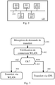
- the Fig. 3 schematically illustrates an algorithm, executed by each smart electricity meter C 120, to receive data from the MDM management entity 130.
- said smart electricity meter C 120 receives, via the communication interface 111 with the communication network by power line carriers 101, a transfer request coming from the MDM management entity 130.
- the MDM management entity 130 indicates that a transfer of data, for the attention of said smart electricity meter C 120, is pending with the MDM management entity 130.
- the transfer request indicates which quantity of data are to be transferred from the MDM management entity 130.
- such a transfer request is a software update intended for said smart electricity meter C 120 or a user profile update associated with a user of said meter smart electric C 120.
- said smart electricity meter C 120 determines whether said smart electricity meter C 120 has a connection, via said communication network 103, with a residential gateway RGW 150 enabling it to communicate with the MDM management entity 130 through it. This aspect is detailed below in relation to the Fig. 5 .
- a step 303 said smart electricity meter C 120 checks whether or not said smart electricity meter C 120 has said connection. If this is the case, a step 304 is carried out; otherwise, a step 305 is performed.
- step 304 said smart electricity meter C 120 organizes the transfer via the communication network 103 of the WLAN type, that is to say by relying on the residential gateway RGW 150 which is the access point AP said communication network 103.
- RGW 150 which is the access point AP said communication network 103.
- step 305 said smart electricity meter C 120 organizes the transfer via the powerline communication network 101, as is usually done in the context of AMM type systems.
- said smart electricity meter C 120 also checks whether the data to be transferred from the management MDM 130 are large or not. Said smart electricity meter C 120 therefore checks whether or not the quantity of data to be transferred from the MDM management entity 130 is greater than the first predefined threshold TH1. If this is the case, said intelligent electricity meter C 120 organizes the transfer via the communication network 103 of the WLAN type if said intelligent electricity meter C 120 has the corresponding connection, and otherwise said intelligent electricity meter C 120 organizes the transfer via the line carrier communication network 101.
- said smart electric meter C 120 knows in advance that such and such a type of transfer is supposed to be organized to be carried out via the communication network 103 of the WLAN type if said electric meter intelligent C 120 has the corresponding connection.
- the transfer request indicates the type of transfer in question (software update, etc.).
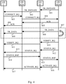
- the Fig. 4 schematically illustrates an exchange of messages within the framework of a data transfer in the communication system of the Fig. 1A , in one embodiment of the present invention.
- a smart electric meter C 120 which has a connection, via a said communication network 103, with a residential gateway RGW 150 allowing it to communicate with the management entity MDM 130 through it.
- the MDM management entity 130 transmits a TR_INITIATE message which indicates to said smart electric meter C 120 that a transfer of data, for the attention of said smart electric meter C 120, is pending with the entity MDM management entity 130.
- the MDM management entity 130 transmits the TR INITIATE message through the data concentrator DC 110 to which said smart electricity meter C 120 is attached. Indeed, the MDM management entity 130 is not informed of the fact that said smart electricity meter C 120 has or does not have an effective connection via a said residential gateway RGW 150.
- the TR_INITIATE message is a message called “image_transfer_initiate”.
- said DC data concentrator 110 forwards said TR INITIATE message to said smart electricity meter C 120 via the power line communication network 101.
- step 403 following the TR INITIATE message and after having verified that you actually have a connection with a residential gateway RGW 150, said smart electricity meter C 120 transmits a CONNECT_RQ message to the MDM management entity 130 via the communication network 103.
- said RGW residential gateway 150 routes the CONNECT_RQ message to the MDM management entity 130 via the communication network 104.
- the CONNECT_RQ message indicates a connection request via the communication network 104 and therefore via said gateway residential RGW 150.
- the CONNECT_RQ message is a connection establishment request in the form of a VPN virtual private network with encrypted transmissions.
- the MDM management entity 130 transmits an ACK message which acknowledges and confirms the connection establishment request of the CONNECT_RQ message.
- the MDM management entity 130 transmits the ACK message to said smart electricity meter C 120 via the communication network 104 and therefore via said residential gateway RGW 150.
- said residential gateway RGW 150 forwards the ACK message to said smart electricity meter C 120 via the communication network 103.
- a step 407 the transfer of data concerned by the TR_INITIATE message is carried out from the MDM management entity 130 to said smart electric meter C 120.
- Said smart electric meter C 120 can retrieve the data in question from the entity management MDM 130 via said residential gateway RGW 150.
- the management entity MDM 130 can push the data in question to said smart electricity meter C 120 via said residential gateway RGW 150, as shown in figure Fig. 4 .
- the MDM management entity 130 transmits part of the data in question in a TR_DATA message, and in a step 409, said RGW residential gateway 150 forwards the TR_DATA message to said smart electricity meter C 120 via the communication network 103. Steps 408 and 409 are repeated until all of the data in question is transmitted from the MDM management entity 130 to said smart electricity meter C 120.
- a transfer protocol of the FTP type (“File Transfer Protocol” in English) can be implemented to execute step 407.
- the MDM management entity 130 and said smart electricity meter C 120 carry out successful transfer confirmation exchanges, via the power line communication network 101, as detailed below in a particular embodiment.
- the MDM management entity 130 transmits a VERIFY_RQ message which instructs said smart electric meter C 120 to carry out an integrity verification of the data received.
- the data typically contains a CRC (Cyclic Redundancy Check) checksum or hash result to do this.
- the MDM management entity 130 transmits the VERIFY_RQ message via the DC 110 data concentrator to which said smart electricity meter C 120 is attached.
- the VERIFY_RQ message is a message called "image_verify".
- said DC data concentrator 110 forwards said VERIFY_RQ message to said C smart electricity meter 120 via the power line communication network 101.
- said C smart electricity meter 120 Upon receipt of the VERIFY_RQ message, said C smart electricity meter 120 performs a verification of integrity of the data received.
- the MDM management entity 130 transmits a STATUS_RQ message which asks said smart electricity meter C 120 to indicate in response what the result of the integrity check is.
- the STATUS_RQ message is a message called “GET(image_transfer_status)”.
- said DC data concentrator 110 forwards said STATUS_RQ message to said smart electricity meter C 120 via the power line communication network 101.
- said smart electricity meter C 120 transmits a STATUS_RSP message intended for the MDM management entity 130 via the communication network by power line carriers 101.
- the STATUS_RSP message includes the result of the integrity check.
- the STATUS_RSP message is a message called “transfer_status”.
- a step 415 said DC data concentrator 110 forwards said STATUS_RSP message to the MDM management entity 130.
- the steps 408 and 409 are repeated for a new transfer.
- the MDM management entity 130 transmits an ACTIVATE_RQ message which instructs said smart electricity meter C 120 to take into account ( ie to activate) the data which has been transferred to it and whose integrity has been successfully verified.
- the message ACTIVATE_RQ instructs said smart electricity meter C 120 to switch to the updated software.
- the ACTIVATE_RQ message is a message called “image_activate”.
- said DC data concentrator 110 forwards said ACTIVATE_RQ message to said smart electric meter C 120 via the power line communication network 101.
- the major part of the exchanges within the framework of the transfer of voluminous data is carried out via the communication networks 103 and 104, whereas the administration messages of the AMM type system are transmitted via the communication network by power line carriers 101, so that said DC data concentrator 110 is informed of the execution of the transfer, as well as potentially the head system HES 140, and above all, this makes it possible to control in particular, thanks to the use of the communication network by power line carriers 101, switching to the downloaded software in the event of a software update download.
- the power line communication network 101 is typically a private communication network while the communication network 104 is typically a public communication network, and the control of the switch to the downloaded software is more secure by performing the transmission of AMM-type system administration messages via the powerline communication network 101.
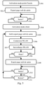
- the Fig. 5 schematically illustrates an algorithm, executed by at least one smart electric meter C 120, for configuring a communication interface of said smart electric meter C120.
- said smart electricity meter C 120 activates an AP access point operating mode on its communication interface 112 adapted to the WLAN networks created and managed by residential gateways RGW 150. Said smart electricity meter C 120 thus allows that wireless terminals connect to it.
- said smart electricity meter C 120 exports, thanks to a web server, an entry web page.
- An installer or user of said C 120 smart electricity meter is then able to enter the WLAN network name (e.g. SSID (“Service Set IDentifier”) and applicable password, using a terminal wireless configuration, via this entry web page.
- SSID Service Set IDentifier
- step 503 said smart electricity meter C 120 checks whether entry of WLAN network name and applicable password is performed or not. If this is the case, a step 504 is carried out; otherwise, step 503 is repeated.
- step 504 said smart electric meter C 120 activates a client operating mode, and in step 505, stops exporting the input web page.
- step 506 said smart electricity meter C 120 makes a connection to the WLAN type communication network whose name and password have been entered.
- the name and password entered are assumed to be the name and password associated with the communication network 103 created and managed by the residential gateway RGW 150 that said smart electricity meter C 120 can use to contact the management entity MDM 150. Note that if the entry turns out to have been incorrect, step 501 is repeated.
- said smart electricity meter C 120 performs monitoring of said WLAN-type communication network, to ensure that said WLAN-type communication network remains operational.
- step 508 said smart electric meter C 120 checks whether there is a loss of connection with said residential gateway RGW 150 or not, that is to say said smart electric meter C 120 checks whether said communication network type WLAN is always present or not. If there has been a loss of connection, a step 509 is carried out; otherwise, step 507 is repeated.
- step 509 said smart electricity meter C 120 again exports the entry web page.
- step 510 said smart electricity meter C 120 checks whether an entry of WLAN network name and applicable password is made or not. If so, step 505 is repeated with that WLAN network name and password. This is the case, for example, when the user replaces his RGW 150 residential gateway with another ( eg when changing Internet service provider operator) or when the user changes the name and/or network password WLAN communication created and generated by its residential gateway RGW 150. Otherwise, a step 511 is performed.
- step 511 said smart electric meter C 120 verifies whether a feedback from the WLAN-type communication network is observed. This is the case, for example, when the user turns his RGW 150 residential gateway back on after having turned it off. If so, step 505 is repeated with the WLAN network name and password that were previously entered; otherwise, step 510 is repeated.
- the access point AP operating mode and the client operating mode of said smart electricity meter C 120 can be active simultaneously, as represented in the Fig. 5 (from step 504).
- the access point AP operating mode and the client operating mode of said smart electricity meter C 120 can be exclusive.
- said smart electricity meter C 120 stops the AP access point operating mode when it activates the client operating mode, and vice versa. More specifically, said smart electricity meter C 120 activates the AP access point operating mode when the entry web page must be exported to obtain the name and password of the communication network 103 created and generated by said residential gateway RGW 150.
- said smart electricity meter C 120 can only export the entry web page when said smart electricity meter C 120 does not have a communication network name and password 103 to which said smart electricity meter C 120 can actually connect (network present, correct password).
- said smart electricity meter C 120 can export the entry web page permanently.
- said smart electricity meter C 120 can only export the entry web page when the user or the installer presses a button on said smart electricity meter C 120, and stop exporting the web page of entered when the user or installer presses said button again or releases said button.
- access to the entry web page is done by entering in a prior web page an administration password, known to said smart electricity meter C 120.
Landscapes
- Engineering & Computer Science (AREA)
- Computer Networks & Wireless Communication (AREA)
- Signal Processing (AREA)
- Power Engineering (AREA)
- General Health & Medical Sciences (AREA)
- Computing Systems (AREA)
- Health & Medical Sciences (AREA)
- Medical Informatics (AREA)
- Physics & Mathematics (AREA)
- General Physics & Mathematics (AREA)
- Telephonic Communication Services (AREA)
- Mobile Radio Communication Systems (AREA)
- Arrangements For Transmission Of Measured Signals (AREA)
- Selective Calling Equipment (AREA)
Claims (11)
- Verfahren zur Übertragung von Daten von einer Managemententität (130) in einem Kommunikationssystem, das außerdem wenigstens eine Datenkonzentratorvorrichtung (110) umfasst, an die intelligente Elektrizitätszähler (120, 121) über ein erstes Powerline-Kommunikationsnetz (101) angeschlossen sind, wobei jede Datenkonzentratorvorrichtung (110) mit der Managemententität (130) über ein zweites Kommunikationsnetz (102) verbunden ist,wobei in dem Verfahren zum Übertragen von Daten von der Managemententität (130) zu einem intelligenten Elektrizitätszähler (120) der intelligente Elektrizitätszähler (120) von der Managemententität (130) über das erste Powerline-Kommunikationsnetz (101) eine Nachricht empfängt, die angibt, dass auf Seiten der Managemententität eine Datenübertragung ansteht;wobei der intelligente Elektrizitätszähler (120) eine drahtlose Kommunikationsschnittstelle (112) enthält, die dafür ausgelegt ist, über ein drittes drahtloses lokales Kommunikationsnetz (103) mit einem residenten Gateway (150), das mit der Managemententität über ein viertes Kommunikationsnetz (104) verbunden ist, zu kommunizieren,wobei in dem Verfahren der intelligente Elektrizitätszähler (120) Daten, die auf Seiten der Managemententität (130) vorhanden sind, über das dritte drahtlose lokale Kommunikationsnetz (103) erhält.
- Verfahren nach Anspruch 1, dadurch gekennzeichnet, dass der intelligente Elektrizitätszähler (120) bei Empfang der Nachricht, die angibt, dass die Übertragung von Daten, die auf Seiten der Managemententität (130) vorhanden sind, ansteht, die folgenden Schritte ausführt:- Bestimmen (302), ob der intelligente Elektrizitätszähler (120) eine Verbindung über das dritte drahtlose lokale Kommunikationsnetz (103) mit dem residenten Gateway (150) herstellt, was ihm erlaubt, darüber mit der Managemententität (130) zu kommunizieren;- Erhalten der Daten, die auf Seiten der Managemententität (130) vorhanden sind, über das dritte drahtlose lokale Kommunikationsnetz (103), wenn der intelligente Elektrizitätszähler (120) eine Verbindung über das dritte drahtlose lokale Kommunikationsnetz (103) mit dem residenten Gateway (150) herstellt; und- Erhalten der Daten, die auf Seiten der Managemententität (130) vorhanden sind, über das erste Powerline-Kommunikationsnetz (101), wenn der intelligente Elektrizitätszähler (120) keine Verbindung über das dritte drahtlose lokale Kommunikationsnetz (103) mit dem residenten Gateway (150) herstellt.
- Verfahren nach Anspruch 2, dadurch gekennzeichnet, dass der intelligente Elektrizitätszähler (120) außerdem verifiziert, ob die von der Managemententität (130) zu übertragende Datenmenge größer als ein erster im Voraus definierter Schwellenwert ist oder nicht, oberhalb dessen die Übertragung dieser Datenmenge durch das Powerline-Kommunikationsnetz (101) eine Wahrscheinlichkeit hat, die höher als ein zweiter im Voraus definierter Schwellenwert ist, bei dem eine Neukonfiguration des Powerline-Kommunikationsnetzes (101) erfolgt, und
dass der intelligente Elektrizitätszähler (120) die Daten, die auf Seiten der Managemententität (130) vorhanden sind, über das dritte drahtlose lokale Kommunikationsnetz (103) erhält, wenn der intelligente Elektrizitätszähler (120) eine Verbindung über das dritte drahtlose lokale Kommunikationsnetz (103) mit dem residenten Gateway (150) herstellt und wenn außerdem die zu übertragende Datenmenge größer als der im Voraus definierte erste Schwellenwert ist. - Verfahren nach Anspruch 2, dadurch gekennzeichnet, dass der intelligente Elektrizitätszähler (120) außerdem verifiziert, ob die von der Managemententität (130) zu übertragende Datenmenge kleiner als ein sogenannter Grenzwert ist oder nicht, der anhand einer im Voraus definierten Kurve und einer Erfolgswahrscheinlichkeit ist, die von der Managemententität (130) geliefert wird und eine Wahrscheinlichkeit dafür darstellt, dass das Powerline-Kommunikationsnetz (101) keine Neukonfiguration während des Fernladens ab dem Zeitpunkt, zu dem der intelligente Elektrizitätszähler (120) mit dem Fernladen beginnt, erfährt, wobei die im Voraus definierte Kurve Mengen fernzuladender Daten mit Werten verknüpft, die Erfolgswahrscheinlichkeiten eines Fernladens darstellen, das über das Powerline-Kommunikationsnetz (101) ausgeführt wird, wobei der intelligente Elektrizitätszähler (120) die Daten, die auf Seiten der Managemententität (130) vorhanden sind, über das Powerline-Kommunikationsnetz (101) erhält, wenn die zu übertragende Datenmenge kleiner als der Grenzwert ist.
- Verfahren nach einem der Ansprüche 2, 3 oder 4, dadurch gekennzeichnet, dass der intelligente Elektrizitätszähler (120) über seine drahtlose Kommunikationsschnittstelle (112) eine Erfassungs-Web-Seite, die ermöglicht, einen Netznamen und ein Passwort zu erfassen, exportiert und dass sich der intelligente Elektrizitätszähler (120) mit dem residenten Gateway (150) kraft des Netznamens und des Passworts, die über die Erfassungs-Web-Seite erfasst worden sind, verbindet.
- Verfahren nach Anspruch 5, dadurch gekennzeichnet, dass der intelligente Elektrizitätszähler (120) die Erfassungs-Web-Seite ausschließlich dann exportiert, wenn der intelligente Elektrizitätszähler (120) den Netznamen und das Passwort nicht angibt, was ermöglicht, seine drahtlose Kommunikationsschnittstelle (112) für die Kommunikation mit der Managemententität (130) zu verwenden.
- Verfahren nach einem der Ansprüche 1 bis 6, dadurch gekennzeichnet, dass der intelligente Elektrizitätszähler (120), nachdem er die Daten, die auf Seiten der Managemententität (130) vorhanden sind, über das dritte drahtlose lokale Kommunikationsnetz (103) erhalten hat, mit der Managemententität (130) einen Austausch einer Bestätigung einer erfolgreichen Übertragung ausführt, wobei der Austausch über das erste Powerline-Kommunikationsnetz (101) erfolgt.
- Verfahren nach einem der Ansprüche 1 bis 6, dadurch gekennzeichnet, dass die drahtlose Kommunikationsschnittstelle (112) vom WiFi-Typ ist.
- Computerprogrammprodukt, dadurch gekennzeichnet, dass es Befehle enthält, die die Ausführung des Verfahrens nach einem der Ansprüche 1 bis 8 zur Folge haben, wenn diese Befehle durch einen Prozessor (201) eines intelligenten Elektrizitätszählers (120) ausgeführt werden.
- Speicherträger, dadurch gekennzeichnet, dass er ein Computerprogramm speichert, das Befehle enthält, die die Ausführung des Verfahrens nach einem der Ansprüche 1 bis 8 zur Folge haben, wenn die Befehle von einem Prozessor (201) eines intelligenten Elektrizitätszählers (120) gelesen und ausgeführt werden.
- Intelligenter Elektrizitätszähler (210), der konfiguriert ist, Daten von einer Managemententität (130) zu empfangen, wobei der Elektrizitätszähler konfiguriert ist, in einem Kommunikationssystem verwendet zu werden, das außerdem wenigstens eine Datenkonzentratorvorrichtung (110) enthält, an die wenigstens der intelligente Elektrizitätszähler (120) über ein erstes Powerline-Kommunikationsnetz (101) angeschlossen werden kann, wobei jede Datenkonzentratorvorrichtung (110) mit der Managemententität (130) über ein zweites Kommunikationsnetz (102) verbunden ist,wobei der intelligente Elektrizitätszähler (120) für die Übertragung von Daten von der Managemententität (130) zu einem intelligenten Elektrizitätszähler (120) Mittel enthält, um von der Managemententität (130) über das erste Powerline-Kommunikationsnetz (101) eine Nachricht zu empfangen, die angibt, dass eine Datenübertragung auf Seiten der Managemententität (130) ansteht;wobei der intelligente Elektrizitätszähler (120) eine drahtlose Kommunikationsschnittstelle (112) enthält, die dafür ausgelegt ist, über ein drittes drahtloses lokales Kommunikationsnetz mit einem residenten Gateway (150) zu kommunizieren, das mit der Managemententität über ein viertes Kommunikationsnetz (104) verbunden ist, und Mittel enthält, um die Daten, die auf Seiten der Managemententität (130) vorhanden sind, über das dritte drahtlose lokale Kommunikationsnetz (103) zu erhalten.
Applications Claiming Priority (2)
| Application Number | Priority Date | Filing Date | Title |
|---|---|---|---|
| FR1852648A FR3079700B1 (fr) | 2018-03-27 | 2018-03-27 | Transmission de donnees depuis une entite de gestion vers un compteur electrique intelligent |
| PCT/EP2019/057633 WO2019185655A1 (fr) | 2018-03-27 | 2019-03-26 | Transmission de données depuis une entité de gestion vers un compteur électrique intelligent |
Publications (2)
| Publication Number | Publication Date |
|---|---|
| EP3777102A1 EP3777102A1 (de) | 2021-02-17 |
| EP3777102B1 true EP3777102B1 (de) | 2022-02-09 |
Family
ID=63014665
Family Applications (1)
| Application Number | Title | Priority Date | Filing Date |
|---|---|---|---|
| EP19713792.0A Active EP3777102B1 (de) | 2018-03-27 | 2019-03-26 | Datenübertragung von einer verwaltungseinheit zu einem intelligenten stromzähler |
Country Status (5)
| Country | Link |
|---|---|
| US (1) | US11658871B2 (de) |
| EP (1) | EP3777102B1 (de) |
| CN (1) | CN111919428A (de) |
| FR (1) | FR3079700B1 (de) |
| WO (1) | WO2019185655A1 (de) |
Families Citing this family (3)
| Publication number | Priority date | Publication date | Assignee | Title |
|---|---|---|---|---|
| CN112630529A (zh) * | 2020-12-29 | 2021-04-09 | 深圳市凌祺实业有限公司 | 一种有电信控系统 |
| CN113933776A (zh) * | 2021-08-31 | 2022-01-14 | 宁波三星智能电气有限公司 | 计量系统数据完整率的自动分析处理方法、介质和设备 |
| CN115988358B (zh) * | 2023-03-22 | 2023-05-23 | 广东电网有限责任公司东莞供电局 | 一种抄表方法、装置、电表及存储介质 |
Family Cites Families (11)
| Publication number | Priority date | Publication date | Assignee | Title |
|---|---|---|---|---|
| US20120173873A1 (en) * | 2011-01-04 | 2012-07-05 | Ray Bell | Smart grid device authenticity verification |
| US9184779B2 (en) * | 2011-07-22 | 2015-11-10 | Texas Instruments Incorporated | Dynamic medium switch in co-located PLC and RF networks |
| US10122171B2 (en) * | 2013-05-31 | 2018-11-06 | Kortek Industries Pty Ltd | Wireless power control and metrics |
| US9191209B2 (en) * | 2013-06-25 | 2015-11-17 | Google Inc. | Efficient communication for devices of a home network |
| FR3016031B1 (fr) * | 2013-12-26 | 2016-02-05 | Grdf | Teledistribution d'une mise a jour logicielle a des terminaux de tele-releve |
| FR3039308B1 (fr) * | 2015-07-21 | 2017-08-18 | Sagemcom Energy & Telecom Sas | Transmission de donnees chiffrees depuis des compteurs electriques intelligents |
| FR3053188B1 (fr) * | 2016-06-28 | 2020-01-31 | Ergylink | Dispositif, systeme et procede pour recevoir selectivement des donnees diffusees dans un reseau |
| KR20180028847A (ko) * | 2016-09-09 | 2018-03-19 | 삼성전자주식회사 | 네트워크 선택 방법 및 그 장치 |
| CN206301319U (zh) * | 2016-12-29 | 2017-07-04 | 国网山东省电力公司青州市供电公司 | 一种电表终端远程升级装置 |
| US10375652B2 (en) * | 2017-12-19 | 2019-08-06 | Itron Global Sarl | Transmission power control for wireless communication devices |
| US11894884B2 (en) * | 2019-09-25 | 2024-02-06 | Alarm.Com Incorporated | Modular electrical grid communications platform |
-
2018
- 2018-03-27 FR FR1852648A patent/FR3079700B1/fr not_active Expired - Fee Related
-
2019
- 2019-03-26 CN CN201980022701.6A patent/CN111919428A/zh active Pending
- 2019-03-26 WO PCT/EP2019/057633 patent/WO2019185655A1/fr unknown
- 2019-03-26 US US16/980,185 patent/US11658871B2/en active Active
- 2019-03-26 EP EP19713792.0A patent/EP3777102B1/de active Active
Also Published As
| Publication number | Publication date |
|---|---|
| CN111919428A (zh) | 2020-11-10 |
| FR3079700A1 (fr) | 2019-10-04 |
| EP3777102A1 (de) | 2021-02-17 |
| WO2019185655A1 (fr) | 2019-10-03 |
| FR3079700B1 (fr) | 2020-10-23 |
| US11658871B2 (en) | 2023-05-23 |
| US20210014111A1 (en) | 2021-01-14 |
Similar Documents
| Publication | Publication Date | Title |
|---|---|---|
| EP3122061B1 (de) | Übertragung von verschlüsselten daten von intelligenten stromzählern aus | |
| US11876637B2 (en) | System and method for providing network support services and premises gateway support infrastructure | |
| EP3777102B1 (de) | Datenübertragung von einer verwaltungseinheit zu einem intelligenten stromzähler | |
| WO2006097615A1 (fr) | Dispositif et procede de communication dans un reseau | |
| EP3182281B1 (de) | Übertragungsverfahren einer neuen software-version an mindestens einen stromzähler über ein kommunikationsnetz | |
| EP3549352B1 (de) | Elektrizitätszähler mit einem stromleitungsschnitstelle und zumindest einem radiofrequenzschnitstelle. | |
| EP3629541A1 (de) | Roaming-verwaltungsverfahren durch multi-netzwerk-transfer | |
| EP2883341B1 (de) | Vorrichtung und verfahren zur bereitstellung von diensten in einem kommunikationsnetz | |
| CA3123438C (fr) | Procede de configuration d'au moins une ressource radio d'un reseau de communication, dispositif noeud, et reseau de communication | |
| EP3797547A1 (de) | Verfahren zur verwaltung einer verbindung in einem verteilten drahtlosen netzwerk | |
| EP3809796B1 (de) | Standby- und reaktivierungsverfahren für zumindest teile eines drahtlosen kommunikationsnetzes und eines sammelknotens des netzes | |
| EP4187874A1 (de) | Verfahren zur konfiguration eines kommunikationsnetzes und knoten zur durchführung des verfahrens | |
| EP4184936A1 (de) | Verfahren zur wiederverbindung eines intelligenten stromzählers und intelligenter stromzähler, der dieses verfahren umsetzt | |
| FR3006530A1 (fr) | Gestion d'acces a un reseau radio-cellulaire | |
| FR2985402A1 (fr) | Procede de connexion a un reseau local d'un terminal mettant en oeuvre un protocole de type eap et systeme de communication associe |
Legal Events
| Date | Code | Title | Description |
|---|---|---|---|
| STAA | Information on the status of an ep patent application or granted ep patent |
Free format text: STATUS: UNKNOWN |
|
| STAA | Information on the status of an ep patent application or granted ep patent |
Free format text: STATUS: THE INTERNATIONAL PUBLICATION HAS BEEN MADE |
|
| PUAI | Public reference made under article 153(3) epc to a published international application that has entered the european phase |
Free format text: ORIGINAL CODE: 0009012 |
|
| STAA | Information on the status of an ep patent application or granted ep patent |
Free format text: STATUS: REQUEST FOR EXAMINATION WAS MADE |
|
| 17P | Request for examination filed |
Effective date: 20200923 |
|
| AK | Designated contracting states |
Kind code of ref document: A1 Designated state(s): AL AT BE BG CH CY CZ DE DK EE ES FI FR GB GR HR HU IE IS IT LI LT LU LV MC MK MT NL NO PL PT RO RS SE SI SK SM TR |
|
| AX | Request for extension of the european patent |
Extension state: BA ME |
|
| DAV | Request for validation of the european patent (deleted) | ||
| DAX | Request for extension of the european patent (deleted) | ||
| RIC1 | Information provided on ipc code assigned before grant |
Ipc: H04B 3/54 20060101ALI20210811BHEP Ipc: G01D 4/00 20060101ALI20210811BHEP Ipc: H04W 4/70 20180101ALI20210811BHEP Ipc: H04L 29/08 20060101AFI20210811BHEP |
|
| GRAP | Despatch of communication of intention to grant a patent |
Free format text: ORIGINAL CODE: EPIDOSNIGR1 |
|
| STAA | Information on the status of an ep patent application or granted ep patent |
Free format text: STATUS: GRANT OF PATENT IS INTENDED |
|
| INTG | Intention to grant announced |
Effective date: 20210923 |
|
| GRAS | Grant fee paid |
Free format text: ORIGINAL CODE: EPIDOSNIGR3 |
|
| GRAA | (expected) grant |
Free format text: ORIGINAL CODE: 0009210 |
|
| STAA | Information on the status of an ep patent application or granted ep patent |
Free format text: STATUS: THE PATENT HAS BEEN GRANTED |
|
| AK | Designated contracting states |
Kind code of ref document: B1 Designated state(s): AL AT BE BG CH CY CZ DE DK EE ES FI FR GB GR HR HU IE IS IT LI LT LU LV MC MK MT NL NO PL PT RO RS SE SI SK SM TR |
|
| REG | Reference to a national code |
Ref country code: GB Ref legal event code: FG4D Free format text: NOT ENGLISH |
|
| REG | Reference to a national code |
Ref country code: CH Ref legal event code: EP Ref country code: AT Ref legal event code: REF Ref document number: 1468220 Country of ref document: AT Kind code of ref document: T Effective date: 20220215 |
|
| REG | Reference to a national code |
Ref country code: DE Ref legal event code: R096 Ref document number: 602019011500 Country of ref document: DE |
|
| REG | Reference to a national code |
Ref country code: IE Ref legal event code: FG4D Free format text: LANGUAGE OF EP DOCUMENT: FRENCH |
|
| REG | Reference to a national code |
Ref country code: LT Ref legal event code: MG9D |
|
| REG | Reference to a national code |
Ref country code: NL Ref legal event code: MP Effective date: 20220209 |
|
| REG | Reference to a national code |
Ref country code: AT Ref legal event code: MK05 Ref document number: 1468220 Country of ref document: AT Kind code of ref document: T Effective date: 20220209 |
|
| PG25 | Lapsed in a contracting state [announced via postgrant information from national office to epo] |
Ref country code: SE Free format text: LAPSE BECAUSE OF FAILURE TO SUBMIT A TRANSLATION OF THE DESCRIPTION OR TO PAY THE FEE WITHIN THE PRESCRIBED TIME-LIMIT Effective date: 20220209 Ref country code: RS Free format text: LAPSE BECAUSE OF FAILURE TO SUBMIT A TRANSLATION OF THE DESCRIPTION OR TO PAY THE FEE WITHIN THE PRESCRIBED TIME-LIMIT Effective date: 20220209 Ref country code: PT Free format text: LAPSE BECAUSE OF FAILURE TO SUBMIT A TRANSLATION OF THE DESCRIPTION OR TO PAY THE FEE WITHIN THE PRESCRIBED TIME-LIMIT Effective date: 20220609 Ref country code: NO Free format text: LAPSE BECAUSE OF FAILURE TO SUBMIT A TRANSLATION OF THE DESCRIPTION OR TO PAY THE FEE WITHIN THE PRESCRIBED TIME-LIMIT Effective date: 20220509 Ref country code: NL Free format text: LAPSE BECAUSE OF FAILURE TO SUBMIT A TRANSLATION OF THE DESCRIPTION OR TO PAY THE FEE WITHIN THE PRESCRIBED TIME-LIMIT Effective date: 20220209 Ref country code: LT Free format text: LAPSE BECAUSE OF FAILURE TO SUBMIT A TRANSLATION OF THE DESCRIPTION OR TO PAY THE FEE WITHIN THE PRESCRIBED TIME-LIMIT Effective date: 20220209 Ref country code: HR Free format text: LAPSE BECAUSE OF FAILURE TO SUBMIT A TRANSLATION OF THE DESCRIPTION OR TO PAY THE FEE WITHIN THE PRESCRIBED TIME-LIMIT Effective date: 20220209 Ref country code: ES Free format text: LAPSE BECAUSE OF FAILURE TO SUBMIT A TRANSLATION OF THE DESCRIPTION OR TO PAY THE FEE WITHIN THE PRESCRIBED TIME-LIMIT Effective date: 20220209 Ref country code: BG Free format text: LAPSE BECAUSE OF FAILURE TO SUBMIT A TRANSLATION OF THE DESCRIPTION OR TO PAY THE FEE WITHIN THE PRESCRIBED TIME-LIMIT Effective date: 20220509 |
|
| PG25 | Lapsed in a contracting state [announced via postgrant information from national office to epo] |
Ref country code: PL Free format text: LAPSE BECAUSE OF FAILURE TO SUBMIT A TRANSLATION OF THE DESCRIPTION OR TO PAY THE FEE WITHIN THE PRESCRIBED TIME-LIMIT Effective date: 20220209 Ref country code: LV Free format text: LAPSE BECAUSE OF FAILURE TO SUBMIT A TRANSLATION OF THE DESCRIPTION OR TO PAY THE FEE WITHIN THE PRESCRIBED TIME-LIMIT Effective date: 20220209 Ref country code: GR Free format text: LAPSE BECAUSE OF FAILURE TO SUBMIT A TRANSLATION OF THE DESCRIPTION OR TO PAY THE FEE WITHIN THE PRESCRIBED TIME-LIMIT Effective date: 20220510 Ref country code: FI Free format text: LAPSE BECAUSE OF FAILURE TO SUBMIT A TRANSLATION OF THE DESCRIPTION OR TO PAY THE FEE WITHIN THE PRESCRIBED TIME-LIMIT Effective date: 20220209 Ref country code: AT Free format text: LAPSE BECAUSE OF FAILURE TO SUBMIT A TRANSLATION OF THE DESCRIPTION OR TO PAY THE FEE WITHIN THE PRESCRIBED TIME-LIMIT Effective date: 20220209 |
|
| PG25 | Lapsed in a contracting state [announced via postgrant information from national office to epo] |
Ref country code: IS Free format text: LAPSE BECAUSE OF FAILURE TO SUBMIT A TRANSLATION OF THE DESCRIPTION OR TO PAY THE FEE WITHIN THE PRESCRIBED TIME-LIMIT Effective date: 20220609 |
|
| PG25 | Lapsed in a contracting state [announced via postgrant information from national office to epo] |
Ref country code: SM Free format text: LAPSE BECAUSE OF FAILURE TO SUBMIT A TRANSLATION OF THE DESCRIPTION OR TO PAY THE FEE WITHIN THE PRESCRIBED TIME-LIMIT Effective date: 20220209 Ref country code: SK Free format text: LAPSE BECAUSE OF FAILURE TO SUBMIT A TRANSLATION OF THE DESCRIPTION OR TO PAY THE FEE WITHIN THE PRESCRIBED TIME-LIMIT Effective date: 20220209 Ref country code: RO Free format text: LAPSE BECAUSE OF FAILURE TO SUBMIT A TRANSLATION OF THE DESCRIPTION OR TO PAY THE FEE WITHIN THE PRESCRIBED TIME-LIMIT Effective date: 20220209 Ref country code: EE Free format text: LAPSE BECAUSE OF FAILURE TO SUBMIT A TRANSLATION OF THE DESCRIPTION OR TO PAY THE FEE WITHIN THE PRESCRIBED TIME-LIMIT Effective date: 20220209 Ref country code: DK Free format text: LAPSE BECAUSE OF FAILURE TO SUBMIT A TRANSLATION OF THE DESCRIPTION OR TO PAY THE FEE WITHIN THE PRESCRIBED TIME-LIMIT Effective date: 20220209 Ref country code: CZ Free format text: LAPSE BECAUSE OF FAILURE TO SUBMIT A TRANSLATION OF THE DESCRIPTION OR TO PAY THE FEE WITHIN THE PRESCRIBED TIME-LIMIT Effective date: 20220209 |
|
| REG | Reference to a national code |
Ref country code: CH Ref legal event code: PL |
|
| REG | Reference to a national code |
Ref country code: DE Ref legal event code: R097 Ref document number: 602019011500 Country of ref document: DE |
|
| PG25 | Lapsed in a contracting state [announced via postgrant information from national office to epo] |
Ref country code: MC Free format text: LAPSE BECAUSE OF FAILURE TO SUBMIT A TRANSLATION OF THE DESCRIPTION OR TO PAY THE FEE WITHIN THE PRESCRIBED TIME-LIMIT Effective date: 20220209 Ref country code: AL Free format text: LAPSE BECAUSE OF FAILURE TO SUBMIT A TRANSLATION OF THE DESCRIPTION OR TO PAY THE FEE WITHIN THE PRESCRIBED TIME-LIMIT Effective date: 20220209 |
|
| REG | Reference to a national code |
Ref country code: BE Ref legal event code: MM Effective date: 20220331 |
|
| PLBE | No opposition filed within time limit |
Free format text: ORIGINAL CODE: 0009261 |
|
| STAA | Information on the status of an ep patent application or granted ep patent |
Free format text: STATUS: NO OPPOSITION FILED WITHIN TIME LIMIT |
|
| 26N | No opposition filed |
Effective date: 20221110 |
|
| PG25 | Lapsed in a contracting state [announced via postgrant information from national office to epo] |
Ref country code: LU Free format text: LAPSE BECAUSE OF NON-PAYMENT OF DUE FEES Effective date: 20220326 Ref country code: LI Free format text: LAPSE BECAUSE OF NON-PAYMENT OF DUE FEES Effective date: 20220331 Ref country code: IE Free format text: LAPSE BECAUSE OF NON-PAYMENT OF DUE FEES Effective date: 20220326 Ref country code: CH Free format text: LAPSE BECAUSE OF NON-PAYMENT OF DUE FEES Effective date: 20220331 |
|
| PG25 | Lapsed in a contracting state [announced via postgrant information from national office to epo] |
Ref country code: SI Free format text: LAPSE BECAUSE OF FAILURE TO SUBMIT A TRANSLATION OF THE DESCRIPTION OR TO PAY THE FEE WITHIN THE PRESCRIBED TIME-LIMIT Effective date: 20220209 Ref country code: BE Free format text: LAPSE BECAUSE OF NON-PAYMENT OF DUE FEES Effective date: 20220331 |
|
| PGFP | Annual fee paid to national office [announced via postgrant information from national office to epo] |
Ref country code: FR Payment date: 20230222 Year of fee payment: 5 |
|
| PG25 | Lapsed in a contracting state [announced via postgrant information from national office to epo] |
Ref country code: IT Free format text: LAPSE BECAUSE OF FAILURE TO SUBMIT A TRANSLATION OF THE DESCRIPTION OR TO PAY THE FEE WITHIN THE PRESCRIBED TIME-LIMIT Effective date: 20220209 |
|
| PG25 | Lapsed in a contracting state [announced via postgrant information from national office to epo] |
Ref country code: MK Free format text: LAPSE BECAUSE OF FAILURE TO SUBMIT A TRANSLATION OF THE DESCRIPTION OR TO PAY THE FEE WITHIN THE PRESCRIBED TIME-LIMIT Effective date: 20220209 Ref country code: CY Free format text: LAPSE BECAUSE OF FAILURE TO SUBMIT A TRANSLATION OF THE DESCRIPTION OR TO PAY THE FEE WITHIN THE PRESCRIBED TIME-LIMIT Effective date: 20220209 |
|
| PGFP | Annual fee paid to national office [announced via postgrant information from national office to epo] |
Ref country code: DE Payment date: 20240220 Year of fee payment: 6 Ref country code: GB Payment date: 20240220 Year of fee payment: 6 |