EP3777102B1 - Data transmission from a management entity to a smart electricity meter - Google Patents
Data transmission from a management entity to a smart electricity meter Download PDFInfo
- Publication number
- EP3777102B1 EP3777102B1 EP19713792.0A EP19713792A EP3777102B1 EP 3777102 B1 EP3777102 B1 EP 3777102B1 EP 19713792 A EP19713792 A EP 19713792A EP 3777102 B1 EP3777102 B1 EP 3777102B1
- Authority
- EP
- European Patent Office
- Prior art keywords
- management entity
- communication network
- electricity meter
- smart electricity
- data
- Prior art date
- Legal status (The legal status is an assumption and is not a legal conclusion. Google has not performed a legal analysis and makes no representation as to the accuracy of the status listed.)
- Active
Links
Images

Classifications
-
- H—ELECTRICITY
- H04—ELECTRIC COMMUNICATION TECHNIQUE
- H04L—TRANSMISSION OF DIGITAL INFORMATION, e.g. TELEGRAPHIC COMMUNICATION
- H04L41/00—Arrangements for maintenance, administration or management of data switching networks, e.g. of packet switching networks
- H04L41/08—Configuration management of networks or network elements
- H04L41/0803—Configuration setting
- H04L41/0813—Configuration setting characterised by the conditions triggering a change of settings
- H04L41/082—Configuration setting characterised by the conditions triggering a change of settings the condition being updates or upgrades of network functionality
-
- G—PHYSICS
- G01—MEASURING; TESTING
- G01R—MEASURING ELECTRIC VARIABLES; MEASURING MAGNETIC VARIABLES
- G01R22/00—Arrangements for measuring time integral of electric power or current, e.g. electricity meters
- G01R22/06—Arrangements for measuring time integral of electric power or current, e.g. electricity meters by electronic methods
- G01R22/061—Details of electronic electricity meters
- G01R22/063—Details of electronic electricity meters related to remote communication
-
- H—ELECTRICITY
- H04—ELECTRIC COMMUNICATION TECHNIQUE
- H04B—TRANSMISSION
- H04B3/00—Line transmission systems
- H04B3/54—Systems for transmission via power distribution lines
-
- H—ELECTRICITY
- H04—ELECTRIC COMMUNICATION TECHNIQUE
- H04B—TRANSMISSION
- H04B3/00—Line transmission systems
- H04B3/54—Systems for transmission via power distribution lines
- H04B3/544—Setting up communications; Call and signalling arrangements
-
- H—ELECTRICITY
- H04—ELECTRIC COMMUNICATION TECHNIQUE
- H04L—TRANSMISSION OF DIGITAL INFORMATION, e.g. TELEGRAPHIC COMMUNICATION
- H04L67/00—Network arrangements or protocols for supporting network services or applications
- H04L67/01—Protocols
- H04L67/06—Protocols specially adapted for file transfer, e.g. file transfer protocol [FTP]
-
- H—ELECTRICITY
- H04—ELECTRIC COMMUNICATION TECHNIQUE
- H04L—TRANSMISSION OF DIGITAL INFORMATION, e.g. TELEGRAPHIC COMMUNICATION
- H04L67/00—Network arrangements or protocols for supporting network services or applications
- H04L67/01—Protocols
- H04L67/12—Protocols specially adapted for proprietary or special-purpose networking environments, e.g. medical networks, sensor networks, networks in vehicles or remote metering networks
-
- H—ELECTRICITY
- H04—ELECTRIC COMMUNICATION TECHNIQUE
- H04L—TRANSMISSION OF DIGITAL INFORMATION, e.g. TELEGRAPHIC COMMUNICATION
- H04L67/00—Network arrangements or protocols for supporting network services or applications
- H04L67/34—Network arrangements or protocols for supporting network services or applications involving the movement of software or configuration parameters
-
- H—ELECTRICITY
- H04—ELECTRIC COMMUNICATION TECHNIQUE
- H04Q—SELECTING
- H04Q9/00—Arrangements in telecontrol or telemetry systems for selectively calling a substation from a main station, in which substation desired apparatus is selected for applying a control signal thereto or for obtaining measured values therefrom
-
- H—ELECTRICITY
- H04—ELECTRIC COMMUNICATION TECHNIQUE
- H04W—WIRELESS COMMUNICATION NETWORKS
- H04W4/00—Services specially adapted for wireless communication networks; Facilities therefor
- H04W4/70—Services for machine-to-machine communication [M2M] or machine type communication [MTC]
-
- H—ELECTRICITY
- H04—ELECTRIC COMMUNICATION TECHNIQUE
- H04Q—SELECTING
- H04Q2209/00—Arrangements in telecontrol or telemetry systems
- H04Q2209/40—Arrangements in telecontrol or telemetry systems using a wireless architecture
-
- H—ELECTRICITY
- H04—ELECTRIC COMMUNICATION TECHNIQUE
- H04Q—SELECTING
- H04Q2209/00—Arrangements in telecontrol or telemetry systems
- H04Q2209/60—Arrangements in telecontrol or telemetry systems for transmitting utility meters data, i.e. transmission of data from the reader of the utility meter
-
- H—ELECTRICITY
- H04—ELECTRIC COMMUNICATION TECHNIQUE
- H04Q—SELECTING
- H04Q2213/00—Indexing scheme relating to selecting arrangements in general and for multiplex systems
- H04Q2213/05—Software aspects
-
- Y—GENERAL TAGGING OF NEW TECHNOLOGICAL DEVELOPMENTS; GENERAL TAGGING OF CROSS-SECTIONAL TECHNOLOGIES SPANNING OVER SEVERAL SECTIONS OF THE IPC; TECHNICAL SUBJECTS COVERED BY FORMER USPC CROSS-REFERENCE ART COLLECTIONS [XRACs] AND DIGESTS
- Y04—INFORMATION OR COMMUNICATION TECHNOLOGIES HAVING AN IMPACT ON OTHER TECHNOLOGY AREAS
- Y04S—SYSTEMS INTEGRATING TECHNOLOGIES RELATED TO POWER NETWORK OPERATION, COMMUNICATION OR INFORMATION TECHNOLOGIES FOR IMPROVING THE ELECTRICAL POWER GENERATION, TRANSMISSION, DISTRIBUTION, MANAGEMENT OR USAGE, i.e. SMART GRIDS
- Y04S40/00—Systems for electrical power generation, transmission, distribution or end-user application management characterised by the use of communication or information technologies, or communication or information technology specific aspects supporting them
- Y04S40/18—Network protocols supporting networked applications, e.g. including control of end-device applications over a network
Definitions
- the present invention relates to data transmission to smart electric meters from a management entity of a communication system to which said electric meters belong.
- a plurality of such data concentrator devices is typically geographically deployed so as to distribute the remote management load of a multitude of smart electricity meters, each data concentrator device then being connected to a same management entity of the AMM type system which is managed by the operator of the electricity supply network to which said smart electricity meters are connected.
- Such line carrier communications must deal with interference related to crosstalk phenomena, and/or unreliability of certain communication links in the line carrier communication network (eg range limit due to to the length of the cables), and/or to noises of different kinds (white noises, colored noises, mainly impulsive noises), and/or to impedance mismatches.
- crosstalk is a phenomenon that allows signals, typically by capacitive coupling, to propagate without passing through actual copper pairs, but through non-visible parasitic links. This phenomenon is unstable, because it can vary according to the temperature or the activity on the communication network by power line carriers.
- the document EP 3 122 061 Al describes a system comprising smart electric meters connected to a concentrator device via a first network by in-line powerline carriers and connected to a collection gateway via a second network of the LPWAN type.
- the invention relates to a method for transmitting data from a management entity in a communication system further comprising at least one data concentrator device to which smart electricity meters are attached via a first communication network by power line carriers, each data concentrator device being connected to the management entity via a second communication network.
- the method being such that, to transmit data from the management entity to a said smart electric meter, said smart electric meter receives, from the management entity, via the first communication network by power line carriers, a message indicating that a data transfer is pending with the management entity.
- said smart electricity meter comprising a wireless communication interface adapted to communicate via a third local wireless communication network with a residential gateway connected to the management entity via a fourth communication network, said smart electricity meter obtains said data from the management entity via the third local wireless communication network.
- said smart electricity meter upon receipt of the message indicating that the data transfer is pending with the management entity, performs the following steps: determining whether said smart electricity meter has a connection, via said third wireless local communication network, with said residential gateway allowing it to communicate with the management entity through it; obtaining said data from the management entity via the third local wireless communication network when said smart electric meter has a connection, via said third local wireless communication network, with said residential gateway; and obtaining said data from the management entity via the first power line communication network when said smart electric meter does not have a connection, via said third local wireless communication network, with said residential gateway .
- said smart electricity meter also checks whether or not the quantity of data to be transferred from the management entity is greater than a first predefined threshold beyond which the transmission of this quantity of data by the network carrier communication network has a probability greater than a second predefined threshold of undergoing a reconfiguration of the powerline communication network. Then, said smart electric meter obtains said data from the management entity via the third local wireless communication network when said smart electric meter has a connection, via said third local wireless communication network, with said residential gateway and further that the quantity of data to be transferred is greater than said first predefined threshold.
- said smart electricity meter also checks whether or not the quantity of data to be transferred from the management entity is less than a value, called the limit value, obtained from a predefined curve linking quantities of data to be downloaded at values representative of probabilities of success of a download carried out via the power line communication network and of a probability of success provided by the management entity representative of a probability that the communication network by carrier currents in line does not undergo a reconfiguration at the time when the electric meter intelligent will start said downloading, said intelligent electricity meter obtaining said data from the management entity via the power line communication network when the amount of data to be transferred is less than the limit value.
- the limit value obtained from a predefined curve linking quantities of data to be downloaded at values representative of probabilities of success of a download carried out via the power line communication network and of a probability of success provided by the management entity representative of a probability that the communication network by carrier currents in line does not undergo a reconfiguration at the time when the electric meter intelligent will start said downloading
- said smart electricity meter exports, via its wireless communication interface, an entry web page to allow entry of a network name and a password, and said smart electricity meter connects to said residential gateway using the network name and password entered via said entry web page.
- said smart electricity meter exports the entry web page only when said smart electricity meter does not have a network name and password allowing its wireless communication interface to be used to communicate with the management entity.
- said smart electricity meter after having obtained said data from the management entity via the third local wireless communication network, said smart electricity meter performs successful transfer confirmation exchanges with the management entity, said exchanges taking place via the first communication network by power line carriers.
- the wireless communication interface is of the Wi-Fi type.
- the invention also relates to a smart electricity meter configured to receive data from a management entity in a communication system further comprising at least one data concentrator device to which at least said smart electricity meter is attached via a first communication network by carrier currents online, each data concentrator device being connected to the management entity via a second communication network.
- said smart electricity meter comprises means for receiving, from the management entity, via the first powerline communication network, a message indicating that a data transfer is pending with the management entity.
- said smart electricity meter comprises a wireless communication interface suitable for communicating via a third wireless local communication network with a residential gateway connected to the management entity via a fourth communication network, and means for get said data from the management entity via the third local wireless communication network.
- the invention also relates to a computer program, which can be stored on a medium and/or downloaded from a communication network, in order to be read by a processor.
- This computer program includes instructions for implementing the method mentioned above, when said program is executed by the processor.
- the invention also relates to storage means comprising such a computer program.
- the Fig. 1A schematically illustrates a communication system in the context of remote automated management of smart electricity meters, in one embodiment of the invention.
- the communications system of the Fig. 1A comprises an MDM (“Meter Data Management”) management entity 130 of said system and a plurality of smart electricity meters C 120, C′ 121.
- MDM Metal Data Management
- the management entity MDM 130 is in particular in charge of collecting information transmitted by the smart electricity meters C 120, C′ 121, such as information on electricity consumption readings of electrical installations that said smart electricity meters C 120, C′ 121 '121 are in charge of monitoring, and for transmitting data, such as software updates and/or user profiles, to said smart electricity meters C 120, C' 121.
- each DC data concentrator device 110 To enable data to be exchanged between the smart electricity meters C 120, C′ 121 and the management entity MDM 130, communications by line carrier currents are established between each of said smart electricity meters C 120, C′ 121 and a DC data concentrator device 110.
- the communication system typically includes a plurality of DC data concentrator devices 110, only one being shown in the Fig. 1A .
- To each DC data concentrator device 110 is logically connected a plurality of smart electric meters C 120, C' 121, each DC data concentrator device 110 thus serving as a relay between said smart electric meters C 120, C' 121 which are connected to it and the MDM management entity 130.
- a line carrier communication network 101 is thus formed between each DC data concentrator device 110 and the plurality of smart electricity meters C 120, C′ 121 connected to it. connected, relying on a power supply network 100 used to supply electricity to the electrical installations that said smart electricity meters C 120, C′ 121 are responsible for monitoring.
- Each smart electricity meter C 120, C′ 121 thus comprises an interface 111 for communication by line carrier currents making it possible to communicate via the communication network by line carrier currents 101.
- each DC data concentrator device 110 comprises such a powerline communication interface 111 allowing communication via the powerline communication network 101.
- the powerline communication network 101 complies with the PRIME specifications.
- the line carrier communication network 101 complies with the G3-PLC standard.
- the topology of the power line communication network 101 is not fixed. Due in particular to the phenomena of crosstalk and other interference, smart electricity meters C 120, C′ 121 may find themselves disconnected from the communication network by line carrier currents 101 and then seek to re-register within the communication network by carrier currents 101. The topology of the powerline communication network 101 at this time is then probably different from the topology of the powerline communication network 101 before disconnection of said smart electricity meters 120.
- each data concentrator device DC 110 further comprises a communication interface 113 with a communication network 102 , to which the MDM management entity 130 is also connected.
- the communication network 102 is preferably a network wireless telecommunications.
- the communication network 102 complies with the UMTS (“Universal Mobile Telecommunications System”) standard.
- the communication network 102 complies with the LTE (“Long Term Evolution”) standard.
- the MDM management entity 130 also comprises a communication interface 113 with the communication network 102 enabling it to communicate with a plurality of DC data concentrator devices 110.
- the communications between the MDM management entity 130 and each data concentrator device DC 110 data can be carried through one or more intermediate servers, as illustrated in the Fig. 1B .
- the MDM management entity 130 is connected to each DC data concentrator device 110 via a HES (Head-End System) system 140 to which the MDM management entity 130 can delegate processing.
- the MDM management entity 130 then comprises a communication interface 113' with a communication network 102' allowing it to communicate with the HES head system 140.
- the HES head system 140 comprises a communication interface 113' with a communication network 102' enabling it to communicate with the MDM management entity 130.
- the HES head system 140 comprises an interface 113 for communication with a communication network 102 enabling it to communicate with one or more DC data concentrator devices 110.
- the communication network 102 ' is for example of the IP type, such as the Internet.
- the management entity MDM 130 preferably complies with the set of IEC 62056 standards, ie with the DLMS (Device Language Message Specification) and COSEM (Companion Specification for Energy Metering) specifications.
- the MDM management entity 130 further comprises a communication interface 114 with an IP-type communication network 104, such as the Internet, to enable it in particular to communicate with residential gateways RGW (“Residential GateWay” in English) 150.
- Residential gateways RGW 150 are typically supplied by Internet access provider operators and installed in private homes or in business premises. In other words, a user who has a C 120 smart electricity meter to manage the power supply of his home or premises also often has an RGW 150 residential gateway to access the Internet from this home. or this place.
- the RGW 150 residential gateways also include a communication interface 114 with the IP-type communication network 104 in particular to enable them to communicate with the MDM management entity 130.
- Each RGW 150 residential gateway also includes a communication interface 112 with a communication network 103 of the WLAN (Wireless Local Area Network) type that said residential gateway RGW 150 creates and manages.
- the communication network 103 is preferably of the Wi-Fi type, as defined in the family of IEEE 802.11 standards.
- the C 120 smart electric meters differ from the C′ 121 smart electric meters in that the C 120 smart electric meters also comprise a communication interface 112 with a communication network of the WLAN type.
- the smart electricity meters C 120 are thus able to communicate with the MDM management entity 130 by relying on a said communication network 103 to use a said residential gateway RGW 150 as a relay with the MDM management entity 130.
- the communication system of the Fig. 1A can not contain only C 120 smart electricity meters, i.e. with the 112 communication interface.
- Such an arrangement of the communication system then offers two alternatives for allowing the smart electricity meters C 120 to receive data from the MDM management entity 130.
- the communication networks 103 and 104 being more stable and able to offer a higher throughput than the communication network by carrier currents in line 101, the smart electric meters C 120 privilege their interface 112 of communication to receive voluminous data coming from the management entity MDM 130.
- voluminous data is meant a quantity of data greater than a first predefined threshold TH1 (for example "200" kBytes) beyond which the transmission of this quantity of data by the powerline communication network 101 has a probability greater than a second threshold TH2 determined dynamically by the MDM 130 to undergo a reconfiguration of the power line communication network 101.
- a first predefined threshold TH1 for example "200" kBytes
- the MDM management entity 130 regularly collects at the level of each smart electric meter C 120, on the one hand a routing table (which indicates communication routes used by said meter), and on the other share a table of neighbors (which indicates other elements of the network with which said counter has exchanged data). From these tables, the MDM management entity 130 determines, for a set of C 120 given smart electricity meters (for example those depending on a given DC 110 data concentrator device), a probability density that the network of line carrier communication 101 connecting the smart electricity meters C 120 of said set to their DC data concentrator device 110 is reconfigured. For this, it measures periods between two reconfigurations and deduces therefrom a Gaussian curve representative of said probability density.
- the MDM management entity 130 launches a time measurement from T0.
- Each instant T following instant T0 is associated with a probability P of failure of a data transmission via the line carrier communication network 101 connecting the C smart electricity meters 120 of said set to their DC data concentrator device 110.
- the failure probability P is an area of the probability density between T0 and T.
- a smart electric meter C 120 of said set when it has to download data coming from the MDM management entity 130, it receives from the MDM management entity 130 a probability of success R concerning said set.
- This probability of success corresponds to the moment when the smart electricity meter will start the download, that is to say it represents the probability that the communication network by online carrier currents 101 connecting the smart electricity meter C 120 to its device data concentrator 110 does not undergo a reconfiguration during the downloading of said meter from the moment when the smart electric meter C 120 will begin its downloading. He also knows what is the quantity of data to download Q.
- the smart electricity meter C 120 has internally a predefined decision curve allowing it to choose whether it can use the communication network by power line carriers 101 for downloading the data or not.
- the predefined decision curve has as abscissa values representative of probabilities R of success of a download performed on the communication network by power line carriers 101 linked to a reconfiguration of the network, and as ordinate values representative of quantities of data to Download. This curve intersects the abscissa axis at the probability value "1" ( ie corresponding to a 100% chance of completely downloading data of size "0" byte via the communication network by online carrier currents 101), and the ordinate axis to a Y0 value.
- Y0 is fixed at 800 kBytes, that is to say that from 800 kBytes, it is considered that the probability of success of a download via the communication network by power line carriers 101 is zero.
- the value Y0 is determined by the MDM management entity 130 and supplied to each smart electric meter C 120.
- the communications between the smart electricity meters C 120, C′ 121 and the MDM management entity 130 are preferably carried out in an encrypted manner, whatever the data path used, for example by establishing virtual private networks VPN (“Virtual Private Network”).
- VPN Virtual Private Network
- the Fig.2 schematically illustrates an example of C 120 smart electricity meter control hardware architecture.
- the smart electricity meter C 120 in question then comprises, connected by a communication bus 210: a processor or CPU (Central Processing Unit) 201; a random access memory RAM (Random Access Memory) 202; a read only memory ROM (Read Only Memory) 203; a storage unit 204, such as a hard disk HDD ("Hard Disk Drive” in English), or a storage medium reader, such as an SD card reader ("Secure Digital” in English); a set of COM interfaces 205 allowing the communication device to communicate within the communication system of the Fig. 1A .
- a processor or CPU Central Processing Unit
- RAM Random Access Memory
- ROM Read Only Memory
- storage unit 204 such as a hard disk HDD ("Hard Disk Drive” in English), or a storage medium reader, such as an SD card reader ("Secure Digital” in English
- a set of COM interfaces 205 allowing the communication device to communicate within the communication system of the Fig. 1A .
- Processor 201 is capable of executing instructions loaded into RAM 202 from ROM 203, external memory (not shown), storage media (such as an SD card), or of a communications network. When the smart electricity meter C 120 in question is powered up, the processor 201 is able to read instructions from the RAM 202 and execute them. These instructions form a computer program causing an implementation, by the processor 201, of all or part of the algorithms and steps described below.
- All or part of the algorithms and steps described below can be implemented in software form by execution of a set of instructions by a programmable machine, for example a DSP (Digital Signal Processor) or a microcontroller, or be implemented in hardware form by a dedicated machine or component, for example an FPGA (Field-Programmable Gate Array) or an ASIC (Application-Specific Integrated Circuit).
- a programmable machine for example a DSP (Digital Signal Processor) or a microcontroller
- a dedicated machine or component for example an FPGA (Field-Programmable Gate Array) or an ASIC (Application-Specific Integrated Circuit).
- each smart electricity meter C 120 thus comprises electronic circuitry configured to implement all or part of the algorithms and steps described below.
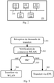
- the Fig. 3 schematically illustrates an algorithm, executed by each smart electricity meter C 120, to receive data from the MDM management entity 130.
- said smart electricity meter C 120 receives, via the communication interface 111 with the communication network by power line carriers 101, a transfer request coming from the MDM management entity 130.
- the MDM management entity 130 indicates that a transfer of data, for the attention of said smart electricity meter C 120, is pending with the MDM management entity 130.
- the transfer request indicates which quantity of data are to be transferred from the MDM management entity 130.
- such a transfer request is a software update intended for said smart electricity meter C 120 or a user profile update associated with a user of said meter smart electric C 120.
- said smart electricity meter C 120 determines whether said smart electricity meter C 120 has a connection, via said communication network 103, with a residential gateway RGW 150 enabling it to communicate with the MDM management entity 130 through it. This aspect is detailed below in relation to the Fig. 5 .
- a step 303 said smart electricity meter C 120 checks whether or not said smart electricity meter C 120 has said connection. If this is the case, a step 304 is carried out; otherwise, a step 305 is performed.
- step 304 said smart electricity meter C 120 organizes the transfer via the communication network 103 of the WLAN type, that is to say by relying on the residential gateway RGW 150 which is the access point AP said communication network 103.
- RGW 150 which is the access point AP said communication network 103.
- step 305 said smart electricity meter C 120 organizes the transfer via the powerline communication network 101, as is usually done in the context of AMM type systems.
- said smart electricity meter C 120 also checks whether the data to be transferred from the management MDM 130 are large or not. Said smart electricity meter C 120 therefore checks whether or not the quantity of data to be transferred from the MDM management entity 130 is greater than the first predefined threshold TH1. If this is the case, said intelligent electricity meter C 120 organizes the transfer via the communication network 103 of the WLAN type if said intelligent electricity meter C 120 has the corresponding connection, and otherwise said intelligent electricity meter C 120 organizes the transfer via the line carrier communication network 101.
- said smart electric meter C 120 knows in advance that such and such a type of transfer is supposed to be organized to be carried out via the communication network 103 of the WLAN type if said electric meter intelligent C 120 has the corresponding connection.
- the transfer request indicates the type of transfer in question (software update, etc.).
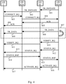
- the Fig. 4 schematically illustrates an exchange of messages within the framework of a data transfer in the communication system of the Fig. 1A , in one embodiment of the present invention.
- a smart electric meter C 120 which has a connection, via a said communication network 103, with a residential gateway RGW 150 allowing it to communicate with the management entity MDM 130 through it.
- the MDM management entity 130 transmits a TR_INITIATE message which indicates to said smart electric meter C 120 that a transfer of data, for the attention of said smart electric meter C 120, is pending with the entity MDM management entity 130.
- the MDM management entity 130 transmits the TR INITIATE message through the data concentrator DC 110 to which said smart electricity meter C 120 is attached. Indeed, the MDM management entity 130 is not informed of the fact that said smart electricity meter C 120 has or does not have an effective connection via a said residential gateway RGW 150.
- the TR_INITIATE message is a message called “image_transfer_initiate”.
- said DC data concentrator 110 forwards said TR INITIATE message to said smart electricity meter C 120 via the power line communication network 101.
- step 403 following the TR INITIATE message and after having verified that you actually have a connection with a residential gateway RGW 150, said smart electricity meter C 120 transmits a CONNECT_RQ message to the MDM management entity 130 via the communication network 103.
- said RGW residential gateway 150 routes the CONNECT_RQ message to the MDM management entity 130 via the communication network 104.
- the CONNECT_RQ message indicates a connection request via the communication network 104 and therefore via said gateway residential RGW 150.
- the CONNECT_RQ message is a connection establishment request in the form of a VPN virtual private network with encrypted transmissions.
- the MDM management entity 130 transmits an ACK message which acknowledges and confirms the connection establishment request of the CONNECT_RQ message.
- the MDM management entity 130 transmits the ACK message to said smart electricity meter C 120 via the communication network 104 and therefore via said residential gateway RGW 150.
- said residential gateway RGW 150 forwards the ACK message to said smart electricity meter C 120 via the communication network 103.
- a step 407 the transfer of data concerned by the TR_INITIATE message is carried out from the MDM management entity 130 to said smart electric meter C 120.
- Said smart electric meter C 120 can retrieve the data in question from the entity management MDM 130 via said residential gateway RGW 150.
- the management entity MDM 130 can push the data in question to said smart electricity meter C 120 via said residential gateway RGW 150, as shown in figure Fig. 4 .
- the MDM management entity 130 transmits part of the data in question in a TR_DATA message, and in a step 409, said RGW residential gateway 150 forwards the TR_DATA message to said smart electricity meter C 120 via the communication network 103. Steps 408 and 409 are repeated until all of the data in question is transmitted from the MDM management entity 130 to said smart electricity meter C 120.
- a transfer protocol of the FTP type (“File Transfer Protocol” in English) can be implemented to execute step 407.
- the MDM management entity 130 and said smart electricity meter C 120 carry out successful transfer confirmation exchanges, via the power line communication network 101, as detailed below in a particular embodiment.
- the MDM management entity 130 transmits a VERIFY_RQ message which instructs said smart electric meter C 120 to carry out an integrity verification of the data received.
- the data typically contains a CRC (Cyclic Redundancy Check) checksum or hash result to do this.
- the MDM management entity 130 transmits the VERIFY_RQ message via the DC 110 data concentrator to which said smart electricity meter C 120 is attached.
- the VERIFY_RQ message is a message called "image_verify".
- said DC data concentrator 110 forwards said VERIFY_RQ message to said C smart electricity meter 120 via the power line communication network 101.
- said C smart electricity meter 120 Upon receipt of the VERIFY_RQ message, said C smart electricity meter 120 performs a verification of integrity of the data received.
- the MDM management entity 130 transmits a STATUS_RQ message which asks said smart electricity meter C 120 to indicate in response what the result of the integrity check is.
- the STATUS_RQ message is a message called “GET(image_transfer_status)”.
- said DC data concentrator 110 forwards said STATUS_RQ message to said smart electricity meter C 120 via the power line communication network 101.
- said smart electricity meter C 120 transmits a STATUS_RSP message intended for the MDM management entity 130 via the communication network by power line carriers 101.
- the STATUS_RSP message includes the result of the integrity check.
- the STATUS_RSP message is a message called “transfer_status”.
- a step 415 said DC data concentrator 110 forwards said STATUS_RSP message to the MDM management entity 130.
- the steps 408 and 409 are repeated for a new transfer.
- the MDM management entity 130 transmits an ACTIVATE_RQ message which instructs said smart electricity meter C 120 to take into account ( ie to activate) the data which has been transferred to it and whose integrity has been successfully verified.
- the message ACTIVATE_RQ instructs said smart electricity meter C 120 to switch to the updated software.
- the ACTIVATE_RQ message is a message called “image_activate”.
- said DC data concentrator 110 forwards said ACTIVATE_RQ message to said smart electric meter C 120 via the power line communication network 101.
- the major part of the exchanges within the framework of the transfer of voluminous data is carried out via the communication networks 103 and 104, whereas the administration messages of the AMM type system are transmitted via the communication network by power line carriers 101, so that said DC data concentrator 110 is informed of the execution of the transfer, as well as potentially the head system HES 140, and above all, this makes it possible to control in particular, thanks to the use of the communication network by power line carriers 101, switching to the downloaded software in the event of a software update download.
- the power line communication network 101 is typically a private communication network while the communication network 104 is typically a public communication network, and the control of the switch to the downloaded software is more secure by performing the transmission of AMM-type system administration messages via the powerline communication network 101.
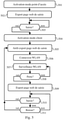
- the Fig. 5 schematically illustrates an algorithm, executed by at least one smart electric meter C 120, for configuring a communication interface of said smart electric meter C120.
- said smart electricity meter C 120 activates an AP access point operating mode on its communication interface 112 adapted to the WLAN networks created and managed by residential gateways RGW 150. Said smart electricity meter C 120 thus allows that wireless terminals connect to it.
- said smart electricity meter C 120 exports, thanks to a web server, an entry web page.
- An installer or user of said C 120 smart electricity meter is then able to enter the WLAN network name (e.g. SSID (“Service Set IDentifier”) and applicable password, using a terminal wireless configuration, via this entry web page.
- SSID Service Set IDentifier
- step 503 said smart electricity meter C 120 checks whether entry of WLAN network name and applicable password is performed or not. If this is the case, a step 504 is carried out; otherwise, step 503 is repeated.
- step 504 said smart electric meter C 120 activates a client operating mode, and in step 505, stops exporting the input web page.
- step 506 said smart electricity meter C 120 makes a connection to the WLAN type communication network whose name and password have been entered.
- the name and password entered are assumed to be the name and password associated with the communication network 103 created and managed by the residential gateway RGW 150 that said smart electricity meter C 120 can use to contact the management entity MDM 150. Note that if the entry turns out to have been incorrect, step 501 is repeated.
- said smart electricity meter C 120 performs monitoring of said WLAN-type communication network, to ensure that said WLAN-type communication network remains operational.
- step 508 said smart electric meter C 120 checks whether there is a loss of connection with said residential gateway RGW 150 or not, that is to say said smart electric meter C 120 checks whether said communication network type WLAN is always present or not. If there has been a loss of connection, a step 509 is carried out; otherwise, step 507 is repeated.
- step 509 said smart electricity meter C 120 again exports the entry web page.
- step 510 said smart electricity meter C 120 checks whether an entry of WLAN network name and applicable password is made or not. If so, step 505 is repeated with that WLAN network name and password. This is the case, for example, when the user replaces his RGW 150 residential gateway with another ( eg when changing Internet service provider operator) or when the user changes the name and/or network password WLAN communication created and generated by its residential gateway RGW 150. Otherwise, a step 511 is performed.
- step 511 said smart electric meter C 120 verifies whether a feedback from the WLAN-type communication network is observed. This is the case, for example, when the user turns his RGW 150 residential gateway back on after having turned it off. If so, step 505 is repeated with the WLAN network name and password that were previously entered; otherwise, step 510 is repeated.
- the access point AP operating mode and the client operating mode of said smart electricity meter C 120 can be active simultaneously, as represented in the Fig. 5 (from step 504).
- the access point AP operating mode and the client operating mode of said smart electricity meter C 120 can be exclusive.
- said smart electricity meter C 120 stops the AP access point operating mode when it activates the client operating mode, and vice versa. More specifically, said smart electricity meter C 120 activates the AP access point operating mode when the entry web page must be exported to obtain the name and password of the communication network 103 created and generated by said residential gateway RGW 150.
- said smart electricity meter C 120 can only export the entry web page when said smart electricity meter C 120 does not have a communication network name and password 103 to which said smart electricity meter C 120 can actually connect (network present, correct password).
- said smart electricity meter C 120 can export the entry web page permanently.
- said smart electricity meter C 120 can only export the entry web page when the user or the installer presses a button on said smart electricity meter C 120, and stop exporting the web page of entered when the user or installer presses said button again or releases said button.
- access to the entry web page is done by entering in a prior web page an administration password, known to said smart electricity meter C 120.
Description
La présente invention concerne une transmission de données vers des compteurs électriques intelligents depuis une entité de gestion d'un système de communication auquel lesdits compteurs électriques appartiennent.The present invention relates to data transmission to smart electric meters from a management entity of a communication system to which said electric meters belong.
Les réseaux de communication par courants porteurs en ligne (« PowerLine Communications » en anglais) pour des systèmes de type AMM (« Automated Meter Management » en anglais) ont fait leur apparition ces dernières années. On peut par exemple citer les spécifications PRIME (« PoweRline Intelligent Metering Evolution » en anglais) et le standard G3-PLC spécifié dans la recommandation ITU-T G.9903. Dans de tels réseaux de communication par courants porteurs en ligne, des communications sont établies entre des compteurs électriques, dits intelligents (« smart electrical meters » en anglais), et un dispositif concentrateur de données (« data concentrator » en anglais), parfois appelé nœud de base (« base node » en anglais), ou coordinateur (« coordinator » en anglais), pour permettre notamment une relève automatisée à distance de mesures de consommation électrique effectuées par lesdits compteurs électriques intelligents. Une pluralité de tels dispositifs concentrateurs de données est typiquement géographiquement déployée de manière à répartir la charge de gestion à distance d'une multitude de compteurs électriques intelligents, chaque dispositif concentrateur de données étant ensuite connecté à une même entité de gestion du système de type AMM qui est gérée par l'opérateur du réseau d'alimentation électrique auquel lesdits compteurs électriques intelligents sont connectés.Communication networks by power line carriers (“PowerLine Communications”) for systems of the AMM (“Automated Meter Management”) type have appeared in recent years. Mention may be made, for example, of the PRIME (Powerline Intelligent Metering Evolution) specifications and the G3-PLC standard specified in the ITU-T recommendation G.9903. In such power line communication networks, communications are established between so-called smart electrical meters, and a data concentrator device, sometimes called base node (“base node” in English), or coordinator (“coordinator” in English), in particular to allow remote automated reading of electricity consumption measurements carried out by said smart electricity meters. A plurality of such data concentrator devices is typically geographically deployed so as to distribute the remote management load of a multitude of smart electricity meters, each data concentrator device then being connected to a same management entity of the AMM type system which is managed by the operator of the electricity supply network to which said smart electricity meters are connected.
De telles communications par courants porteurs en ligne doivent faire face à des interférences liées à des phénomènes de diaphonie, et/ou à un manque de fiabilité de certains liens de communication dans le réseau de communication par courants porteurs en ligne (e.g. limite de portée due à la longueur des câbles), et/ou à des bruits de différentes natures (bruits blancs, bruits colorés, bruits impulsionnels principalement), et/ou à des désadaptations d'impédance. Pour rappel, la diaphonie est un phénomène qui permet à des signaux, typiquement par couplage capacitif, de se propager sans passer par des paires de cuivre proprement dites, mais par des liens parasites non visibles. Ce phénomène est instable, car pouvant varier en fonction de la température ou de l'activité sur le réseau de communication par courants porteurs en ligne. A noter qu'il peut également y avoir de la diaphonie au sein d'un même appareil via des liaisons cuivre sur circuits imprimés et/ou via certains composants qui constituent ledit appareil. Ces phénomènes peuvent entraîner des pertes de paquets ou messages, notamment de paquets ou messages de signalisation, et entraîner des déconnexions de dispositifs nœuds du réseau de communication. Une telle instabilité des réseaux de communication par courants porteurs en ligne rend problématique la transmission de données vers les compteurs électriques intelligents depuis l'entité de gestion du système de type AMM, notamment en termes de latence puisque, par exemple, les reconfigurations du réseau de communication suite à des déconnexions de compteurs électriques intelligents, dont certains servent de relais entre un dispositif concentrateur de données et d'autres compteurs électriques intelligents, sont longues et fastidieuses.Such line carrier communications must deal with interference related to crosstalk phenomena, and/or unreliability of certain communication links in the line carrier communication network ( eg range limit due to to the length of the cables), and/or to noises of different kinds (white noises, colored noises, mainly impulsive noises), and/or to impedance mismatches. As a reminder, crosstalk is a phenomenon that allows signals, typically by capacitive coupling, to propagate without passing through actual copper pairs, but through non-visible parasitic links. This phenomenon is unstable, because it can vary according to the temperature or the activity on the communication network by power line carriers. To note that there may also be crosstalk within the same device via copper connections on printed circuits and/or via certain components which constitute said device. These phenomena can lead to loss of packets or messages, in particular signaling packets or messages, and lead to disconnection of node devices from the communication network. Such instability of power line carrier communication networks makes the transmission of data to smart electricity meters from the management entity of the AMM-type system problematic, particularly in terms of latency since, for example, reconfigurations of the communication following disconnections of smart electricity meters, some of which serve as a relay between a data concentrator device and other smart electricity meters, is long and tedious.
Le document
Le document
Il est souhaitable de pallier ces inconvénients de l'état de la technique, et notamment d'améliorer les capacités de transmission de données vers les compteurs électriques intelligents depuis l'entité de gestion du système de type AMM, notamment dans le cadre de mise à jour logicielle des compteurs électriques intelligents et/ou de mise à jour de profils utilisateurs associés à des utilisateurs de ces compteurs électriques intelligents.It is desirable to overcome these drawbacks of the state of the art, and in particular to improve the capacities for transmitting data to the smart electricity meters from the management entity of the AMM type system, in particular in the context of updating. software update of smart electricity meters and/or update of user profiles associated with users of these smart electricity meters.
L'invention concerne un procédé pour transmettre des données depuis une entité de gestion dans un système de communication comportant en outre au moins un dispositif concentrateur de données auquel sont rattachés des compteurs électriques intelligents via un premier réseau de communication par courants porteurs en ligne, chaque dispositif concentrateur de données étant connecté à l'entité de gestion via un second réseau de communication. Le procédé étant tel que, pour transmettre des données depuis l'entité de gestion vers un dit compteur électrique intelligent, ledit compteur électrique intelligent reçoit, en provenance de l'entité de gestion, via le premier réseau de communication par courants porteurs en ligne, un message indiquant qu'un transfert de données est en attente auprès de l'entité de gestion. De plus, ledit compteur électrique intelligent comportant une interface de communication sans-fil adaptée pour communiquer via un troisième réseau de communication local sans-fil avec une passerelle résidentielle connectée à l'entité de gestion via un quatrième réseau de communication, ledit compteur électrique intelligent obtient lesdites données auprès de l'entité de gestion via le troisième réseau de communication local sans-fil. Ainsi, grâce au troisième réseau de communication local sans-fil et à la passerelle résidentielle, le transfert des données depuis l'entité de gestion jusqu'audit compteur électrique intelligent est plus performant, en évitant de recourir au premier réseau de communication par courants porteurs en ligne pour le transfert desdites données.The invention relates to a method for transmitting data from a management entity in a communication system further comprising at least one data concentrator device to which smart electricity meters are attached via a first communication network by power line carriers, each data concentrator device being connected to the management entity via a second communication network. The method being such that, to transmit data from the management entity to a said smart electric meter, said smart electric meter receives, from the management entity, via the first communication network by power line carriers, a message indicating that a data transfer is pending with the management entity. In addition, said smart electricity meter comprising a wireless communication interface adapted to communicate via a third local wireless communication network with a residential gateway connected to the management entity via a fourth communication network, said smart electricity meter obtains said data from the management entity via the third local wireless communication network. Thus, thanks to the third local wireless communication network and the residential gateway, the transfer of data from the management entity to said electricity meter intelligent is more efficient, by avoiding the need to use the first communication network by power line carriers for the transfer of said data.
Selon un mode de réalisation particulier, sur réception du message indiquant que le transfert de données est en attente auprès de l'entité de gestion, ledit compteur électrique intelligent effectue les étapes suivantes : déterminer si ledit compteur électrique intelligent dispose d'une connexion, via ledit troisième réseau de communication local sans-fil, avec ladite passerelle résidentielle lui permettant de communiquer avec l'entité de gestion par son biais ; obtenir lesdites données auprès de l'entité de gestion via le troisième réseau de communication local sans-fil lorsque ledit compteur électrique intelligent dispose d'une connexion, via ledit troisième réseau de communication local sans-fil, avec ladite passerelle résidentielle ; et obtenir lesdites données auprès de l'entité de gestion via le premier réseau de communication par courants porteurs en ligne lorsque ledit compteur électrique intelligent ne dispose pas d'une connexion, via ledit troisième réseau de communication local sans-fil, avec ladite passerelle résidentielle.According to a particular embodiment, upon receipt of the message indicating that the data transfer is pending with the management entity, said smart electricity meter performs the following steps: determining whether said smart electricity meter has a connection, via said third wireless local communication network, with said residential gateway allowing it to communicate with the management entity through it; obtaining said data from the management entity via the third local wireless communication network when said smart electric meter has a connection, via said third local wireless communication network, with said residential gateway; and obtaining said data from the management entity via the first power line communication network when said smart electric meter does not have a connection, via said third local wireless communication network, with said residential gateway .
Selon un mode de réalisation particulier, ledit compteur électrique intelligent vérifie en outre si la quantité de données à transférer depuis l'entité de gestion est ou pas supérieure à un premier seuil prédéfini au-delà duquel la transmission de cette quantité de données par le réseau de communication par courants porteurs en ligne a une probabilité supérieure à un second seuil prédéfini de subir une reconfiguration du réseau de communication par courants porteurs en ligne. Alors, ledit compteur électrique intelligent obtient lesdites données auprès de l'entité de gestion via le troisième réseau de communication local sans-fil lorsque ledit compteur électrique intelligent dispose d'une connexion, via ledit troisième réseau de communication local sans-fil, avec ladite passerelle résidentielle et en outre que la quantité de données à transférer est supérieure audit premier seuil prédéfini.According to a particular embodiment, said smart electricity meter also checks whether or not the quantity of data to be transferred from the management entity is greater than a first predefined threshold beyond which the transmission of this quantity of data by the network carrier communication network has a probability greater than a second predefined threshold of undergoing a reconfiguration of the powerline communication network. Then, said smart electric meter obtains said data from the management entity via the third local wireless communication network when said smart electric meter has a connection, via said third local wireless communication network, with said residential gateway and further that the quantity of data to be transferred is greater than said first predefined threshold.
Selon un mode de réalisation, ledit compteur électrique intelligent vérifie en outre si la quantité de données à transférer depuis l'entité de gestion est ou pas inférieure à une valeur, dite valeur limite, obtenue à partir d'une courbe prédéfinie reliant des quantités de données à télécharger à des valeurs représentatives de probabilités de réussite d'un téléchargement effectué via le réseau de communication par courants porteurs en ligne et d'une probabilité de réussite fournie par l'entité de gestion représentative d'une probabilité que le réseau de communication par courants porteurs en ligne ne subisse pas une reconfiguration au moment où le compteur électrique intelligent débutera ledit téléchargement, ledit compteur électrique intelligent obtenant lesdites données auprès de l'entité de gestion via le réseau de communication par courant porteur en ligne lorsque la quantité de données à transférer est inférieure à la valeur limite.According to one embodiment, said smart electricity meter also checks whether or not the quantity of data to be transferred from the management entity is less than a value, called the limit value, obtained from a predefined curve linking quantities of data to be downloaded at values representative of probabilities of success of a download carried out via the power line communication network and of a probability of success provided by the management entity representative of a probability that the communication network by carrier currents in line does not undergo a reconfiguration at the time when the electric meter intelligent will start said downloading, said intelligent electricity meter obtaining said data from the management entity via the power line communication network when the amount of data to be transferred is less than the limit value.
Selon un mode de réalisation particulier, ledit compteur électrique intelligent exporte, via son interface de communication sans-fil, une page web de saisie pour permettre de saisir un nom de réseau et un mot de passe, et ledit compteur électrique intelligent se connecte à ladite passerelle résidentielle grâce au nom de réseau et au mot de passe saisis via ladite page web de saisie.According to a particular embodiment, said smart electricity meter exports, via its wireless communication interface, an entry web page to allow entry of a network name and a password, and said smart electricity meter connects to said residential gateway using the network name and password entered via said entry web page.
Selon un mode de réalisation particulier, ledit compteur électrique intelligent exporte la page web de saisie uniquement lorsque ledit compteur électrique intelligent ne dispose pas de nom de réseau et de mot de passe permettant d'utiliser son interface de communication sans-fil pour communiquer avec l'entité de gestion.According to a particular embodiment, said smart electricity meter exports the entry web page only when said smart electricity meter does not have a network name and password allowing its wireless communication interface to be used to communicate with the management entity.
Selon un mode de réalisation particulier, après avoir obtenu lesdites données auprès de l'entité de gestion via le troisième réseau de communication local sans-fil, ledit compteur électrique intelligent effectue avec l'entité de gestion des échanges de confirmation de transfert réussi, lesdits échanges s'effectuant via le premier réseau de communication par courants porteurs en ligne.According to a particular embodiment, after having obtained said data from the management entity via the third local wireless communication network, said smart electricity meter performs successful transfer confirmation exchanges with the management entity, said exchanges taking place via the first communication network by power line carriers.
Selon un mode de réalisation particulier, l'interface de communication sans-fil est de type Wi-Fi.According to a particular embodiment, the wireless communication interface is of the Wi-Fi type.
L'invention concerne également un compteur électrique intelligent configuré pour recevoir des données depuis une entité de gestion dans un système de communication comportant en outre au moins un dispositif concentrateur de données auquel est rattaché au moins ledit compteur électrique intelligent via un premier réseau de communication par courants porteurs en ligne, chaque dispositif concentrateur de données étant connecté à l'entité de gestion via un second réseau de communication. Pour transmettre des données depuis l'entité de gestion vers ledit compteur électrique intelligent, ledit compteur électrique intelligent comporte des moyens pour recevoir, en provenance de l'entité de gestion, via le premier réseau de communication par courants porteurs en ligne, un message indiquant qu'un transfert de données est en attente auprès de l'entité de gestion. De plus, ledit compteur électrique intelligent comporte une interface de communication sans-fil adaptée pour communiquer via un troisième réseau de communication local sans-fil avec une passerelle résidentielle connectée à l'entité de gestion via un quatrième réseau de communication, et des moyens pour obtenir lesdites données auprès de l'entité de gestion via le troisième réseau de communication local sans-fil.The invention also relates to a smart electricity meter configured to receive data from a management entity in a communication system further comprising at least one data concentrator device to which at least said smart electricity meter is attached via a first communication network by carrier currents online, each data concentrator device being connected to the management entity via a second communication network. To transmit data from the management entity to said smart electricity meter, said smart electricity meter comprises means for receiving, from the management entity, via the first powerline communication network, a message indicating that a data transfer is pending with the management entity. In addition, said smart electricity meter comprises a wireless communication interface suitable for communicating via a third wireless local communication network with a residential gateway connected to the management entity via a fourth communication network, and means for get said data from the management entity via the third local wireless communication network.
L'invention concerne également un programme d'ordinateur, qui peut être stocké sur un support et/ou téléchargé d'un réseau de communication, afin d'être lu par un processeur. Ce programme d'ordinateur comprend des instructions pour implémenter le procédé mentionné ci-dessus, lorsque ledit programme est exécuté par le processeur. L'invention concerne également des moyens de stockage comprenant un tel programme d'ordinateur.The invention also relates to a computer program, which can be stored on a medium and/or downloaded from a communication network, in order to be read by a processor. This computer program includes instructions for implementing the method mentioned above, when said program is executed by the processor. The invention also relates to storage means comprising such a computer program.
Les caractéristiques de l'invention mentionnées ci-dessus, ainsi que d'autres, apparaîtront plus clairement à la lecture de la description suivante d'un exemple de réalisation, ladite description étant faite en relation avec les dessins joints, parmi lesquels :
- la
Fig. 1A illustre schématiquement un système de communication dans le cadre d'une gestion automatisée à distance de compteurs électriques intelligents, dans un mode de réalisation de l'invention ; - la
Fig. 1B illustre schématiquement une variante d'agencement d'une partie du système de communication de laFig. 1A ; - la
Fig. 2 illustre schématiquement un exemple d'architecture matérielle de contrôle d'un compteur électrique intelligent du système de communication de laFig. 1A ; - la
Fig. 3 illustre schématiquement un algorithme, exécuté par au moins un compteur électrique intelligent du système de laFig. 1A , pour recevoir des données depuis une entité de gestion du système de laFig. 1A ; - la
Fig. 4 illustre schématiquement un échange de messages dans le cadre d'un transfert de données dans le système de communication de laFig. 1A , dans un mode de réalisation de la présente invention ; et - la
Fig. 5 illustre schématiquement un algorithme, exécuté par au moins un compteur électrique intelligent du système de laFig. 1A , pour configurer une interface de communication dudit compteur électrique intelligent.
- the
Fig. 1A schematically illustrates a communication system in the context of remote automated management of smart electric meters, in one embodiment of the invention; - the
Fig. 1B schematically illustrates a variant arrangement of part of the communication system of theFig. 1A ; - the
Fig. 2 schematically illustrates an example of control hardware architecture of a smart electricity meter of the communication system of theFig. 1A ; - the
Fig. 3 schematically illustrates an algorithm, executed by at least one smart electricity meter of the system of theFig. 1A , to receive data from a system management entity of theFig. 1A ; - the
Fig. 4 schematically illustrates an exchange of messages within the framework of a data transfer in the communication system of theFig. 1A , in one embodiment of the present invention; and - the
Fig. 5 schematically illustrates an algorithm, executed by at least one smart electricity meter of the system of theFig. 1A , to configure a communication interface of said smart electricity meter.
La
Le système de communication de la
L'entité de gestion MDM 130 est notamment en charge de collecter des informations transmises par les compteurs électriques intelligents C 120, C' 121, telles que des informations de relevés de consommation électrique d'installations électriques que lesdits compteurs électriques intelligents C 120, C' 121 sont en charge de surveiller, et pour transmettre des données, telles que des mises à jour logicielles et/ou des profils utilisateurs, auxdits compteurs électriques intelligents C 120, C' 121.The
Pour permettre d'échanger des données entre les compteurs électriques intelligents C 120, C' 121 et l'entité de gestion MDM 130, des communications par courants porteurs en ligne sont établies entre chacun desdits compteurs électriques intelligents C 120, C' 121 et un dispositif concentrateur de données DC 110. Le système de communication comporte typiquement une pluralité de dispositifs concentrateurs de données DC 110, un seul étant représenté sur la
Chaque compteur électrique intelligent C 120, C' 121 comporte ainsi une interface 111 de communication par courants porteurs en ligne permettant de communiquer via le réseau de communication par courants porteurs en ligne 101. De même, chaque dispositif concentrateur de données DC 110 comporte une telle interface 111 de communication par courants porteurs en ligne permettant de communiquer via le réseau de communication par courants porteurs en ligne 101. Selon un exemple de réalisation, le réseau de communication par courants porteurs en ligne 101 est conforme aux spécifications PRIME. Selon un autre exemple de réalisation, le réseau de communication par courants porteurs en ligne 101 est conforme au standard G3-PLC.Each smart
Il faut comprendre que la topologie du réseau de communication par courants porteurs en ligne 101 n'est pas figée. A cause notamment des phénomènes de diaphonie et autres interférences, des compteurs électriques intelligents C 120, C' 121 peuvent se trouver déconnectés du réseau de communication par courants porteurs en ligne 101 et cherchent alors à se réenregistrer au sein du réseau de communication par courants porteurs en ligne 101. La topologie du réseau de communication par courants porteurs en ligne 101 à ce moment-là est alors probablement différente de la topologie du réseau de communication par courants porteurs en ligne 101 avant déconnexion desdits compteurs électriques intelligents 120.It should be understood that the topology of the power
Pour permettre de relayer les informations échangées entre les compteurs électriques intelligents C 120, C' 121 à destination de l'entité de gestion MDM 130, chaque dispositif concentrateur de données DC 110 comporte en outre une interface 113 de communication avec un réseau de communication 102, auquel est aussi connectée l'entité de gestion MDM 130. Etant donné que les dispositifs concentrateurs de données DC 110 peuvent être typiquement installés au sein de postes de transformation du réseau d'alimentation électrique 100, le réseau de communication 102 est préférentiellement un réseau de télécommunication sans-fil. Selon un exemple de réalisation, le réseau de communication 102 est conforme au standard UMTS (« Universal Mobile Telecommunications System » en anglais). Selon un autre exemple de réalisation, le réseau de communication 102 est conforme au standard LTE (« Long Term Evolution » en anglais).To enable the information exchanged between the smart
L'entité de gestion MDM 130 comporte aussi une interface 113 de communication avec le réseau de communication 102 lui permettant de communiquer avec une pluralité de dispositifs concentrateurs de données DC 110. Les communications entre l'entité de gestion MDM 130 et chaque dispositif concentrateur de données DC 110 peuvent s'effectuer via un ou plusieurs serveurs intermédiaires, comme illustré sur la
Sur la
L'entité de gestion MDM 130 est préférentiellement conforme à l'ensemble de standards IEC 62056, i.e. aux spécifications DLMS (« Device Language Message Spécification » en anglais) et COSEM (« Companion Specification for Energy Metering » en anglais).The
L'entité de gestion MDM 130 comporte en outre une interface 114 de communication avec un réseau de communication 104 de type IP, tel que l'Internet, pour lui permettre notamment de communiquer avec des passerelles résidentielles RGW (« Résidentiel GateWay » en anglais) 150. De telles passerelles résidentielles RGW 150 sont typiquement fournies par des opérateurs fournisseurs d'accès à l'Internet et installées chez les particuliers ou dans des locaux d'entreprise. En d'autres termes, un utilisateur qui dispose d'un compteur électrique intelligent C 120 pour gérer l'alimentation électrique de son habitation ou de son local dispose aussi souvent d'une passerelle résidentielle RGW 150 pour accéder à l'Internet depuis cette habitation ou ce local.The
Les passerelles résidentielles RGW 150 comportent aussi une interface 114 de communication avec le réseau de communication 104 de type IP pour notamment leur permettre de communiquer avec l'entité de gestion MDM 130. Chaque passerelle résidentielle RGW 150 comporte en outre une interface 112 de communication avec un réseau de communication 103 de type WLAN (« Wireless Local Area Network » en anglais) que ladite passerelle résidentielle RGW 150 crée et gère. Le réseau de communication 103 est préférentiellement de type Wi-Fi, tel que défini dans la famille de standard IEEE 802.11.The
Les compteurs électriques intelligents C 120 diffèrent des compteurs électriques intelligents C' 121 en ce que les compteurs électriques intelligents C 120 comportent en outre une interface de communication 112 avec un réseau de communication de type WLAN. Les compteurs électriques intelligents C 120 sont ainsi aptes à communiquer avec l'entité de gestion MDM 130 en s'appuyant sur un dit réseau de communication 103 pour utiliser une dite passerelle résidentielle RGW 150 comme relais avec l'entité de gestion MDM 130. A noter que le système de communication de la
Un tel agencement du système de communication offre alors deux alternatives pour permettre aux compteurs électriques intelligents C 120 de recevoir des données depuis l'entité de gestion MDM 130. Les réseaux de communication 103 et 104 étant plus stables et pouvant offrir un débit plus important que le réseau de communication par courants porteurs en ligne 101, les compteurs électriques intelligents C 120 privilégient leur interface 112 de communication pour recevoir des données volumineuses en provenance de l'entité de gestion MDM 130. On entend par « données volumineuses » une quantité de données supérieure à un premier seuil TH1 prédéfini (par exemple « 200 » kOctets) au-delà duquel la transmission de cette quantité de données par le réseau de communication par courants porteurs en ligne 101 a une probabilité supérieure à un second seuil TH2 déterminé dynamiquement par le MDM 130 de subir une reconfiguration du réseau de communication par courants porteurs en ligne 101. Par exemple, le transfert d'une mise à jour logicielle des compteurs électriques intelligents C 120 est typiquement considérée comme un transfert de données volumineuses.Such an arrangement of the communication system then offers two alternatives for allowing the smart
Cependant, les communications par courants porteurs en ligne sont garanties alors que les communications via Wi-Fi ne le sont pas.However, power line communications are guaranteed while communications over Wi-Fi are not.
Dans un mode de réalisation, l'entité de gestion MDM 130 collecte régulièrement au niveau de chaque compteur électrique intelligent C 120, d'une part une table de routage (qui indique des routes de communication utilisées par ledit compteur), et d'autre part une table des voisins (qui indique d'autres éléments du réseau avec lequel ledit compteur a échangé des données). A partir de ces tables, l'entité de gestion MDM 130 détermine, pour un ensemble de compteurs électriques intelligents C 120 donnés (par exemple ceux dépendant d'un dispositif concentrateur de données DC 110 donné), une densité de probabilité que le réseau de communication par courants porteurs en ligne 101 reliant les compteurs électriques intelligents C 120 dudit ensemble à leur dispositif concentrateur de données DC 110 se reconfigure. Il mesure pour cela des périodes entre deux reconfigurations et en déduit une courbe de Gauss représentative de ladite densité de probabilité. Ainsi, lorsqu'une reconfiguration du réseau de communication par courants porteurs en ligne 101 se produit à un instant T0, l'entité de gestion MDM 130 lance une mesure de temps à partir de T0. Chaque instant T suivant l'instant T0 est associé à une probabilité P d'échec d'une transmission de données via le réseau de communication par courants porteurs en ligne 101 reliant les compteurs électriques intelligents C 120 dudit ensemble à leur dispositif concentrateur de données DC 110. La probabilité d'échec P est une aire de la densité de probabilité entre T0 et T. In one embodiment, the
On nomme R une probabilité de réussite associée à P. R=1-P. We call R a probability of success associated with P. R = 1-P.
Ainsi, lorsqu'un compteur électrique intelligent C 120 dudit ensemble doit télécharger des données en provenance de l'entité de gestion MDM 130, il reçoit de l'entité de gestion MDM 130 une probabilité de réussite R concernant ledit ensemble. Cette probabilité de réussite correspond au moment où le compteur électrique intelligent débutera le téléchargement, c'est-à-dire qu'elle représente la probabilité que le réseau de communication par courants porteurs en ligne 101 reliant le compteur électrique intelligent C 120 à son dispositif concentrateur de données 110 ne subisse pas une reconfiguration pendant le téléchargement dudit compteur à partir du moment où le compteur électrique intelligent C 120 débutera son téléchargement. Il sait de plus quelle est la quantité des données à télécharger Q. Thus, when a smart
Le compteur électrique intelligent C 120 dispose en interne d'une courbe de décision prédéfinie lui permettant de choisir s'il peut utiliser le réseau de communication par courants porteurs en ligne 101 pour le téléchargement des données ou pas. La courbe de décision prédéfinie a pour abscisse des valeurs représentatives de probabilités R de réussite d'un téléchargement effectué sur le réseau de communication par courants porteurs en ligne 101 liée à une reconfiguration du réseau, et pour ordonnée des valeurs représentatives de quantités de données à télécharger. Cette courbe coupe l'axe des abscisses à la valeur de probabilité « 1 » (i.e. correspondant à 100% de chance de télécharger intégralement des données de taille « 0 » octet par le réseau de communication par courants porteurs en ligne 101), et l'axe des ordonnées à une valeur Y0. Dans un mode de réalisation, Y0 est fixée à 800 kOctets, c'est-à-dire qu'à partir de 800 kOctets, on considère que la probabilité de réussite d'un téléchargement via le réseau de communication par courants porteurs en ligne 101 est nulle. Dans un mode de réalisation, la valeur Y0 est déterminée par l'entité de gestion MDM 130 et fournie à chaque compteur électrique intelligent C 120. Dans un mode de réalisation, la courbe prédéfinie est une droite d'équation y = -Y0(r) + Y0, ou r (=1-p) est une valeur de probabilité comprise entre zéro et l'unité.The smart
Le compteur électrique intelligent C 120 prend la décision d'effectuer un téléchargement via le réseau de communication par courants porteurs en ligne 101 si, pour la probabilité de réussite R fournie par l'entité de gestion MDM 130, la quantité de données à télécharger Q est inférieure à yR = -Y0(R) + Y0. Sinon, Le compteur électrique intelligent C 120 prend la décision d'effectuer un téléchargement via les réseaux de communication 103 et 104. On suppose ici que le compteur électrique intelligent C 120 prend la décision dès réception de la probabilité R, et commence le téléchargement immédiatement après la prise de décision, de sorte que la probabilité R fournie par l'entité de gestion MDM 130 est valide pour ledit téléchargement.The smart
A noter que les communications entre les compteurs électriques intelligents C 120, C' 121 et l'entité de gestion MDM 130 s'effectuent préférentiellement de manière chiffrée, quel que soit le chemin de données utilisé, par exemple en établissant des réseaux privés virtuels VPN (« Virtual Private Network » en anglais).It should be noted that the communications between the smart
La
Le compteur électrique intelligent C 120 en question comprend alors, reliés par un bus de communication 210 : un processeur ou CPU (« Central Processing Unit » en anglais) 201 ; une mémoire vive RAM (« Random Access Memory » en anglais) 202 ; une mémoire morte ROM (« Read Only Memory » en anglais) 203 ; une unité de stockage 204, tel qu'un disque dur HDD (« Hard Disk Drive » en anglais), ou un lecteur de support de stockage, tel qu'un lecteur de cartes SD (« Secure Digital » en anglais) ; un ensemble d'interfaces COM 205 permettant au dispositif de communication de communiquer au sein du système de communication de la
Le processeur 201 est capable d'exécuter des instructions chargées dans la mémoire RAM 202 à partir de la mémoire ROM 203, d'une mémoire externe (non représentée), d'un support de stockage (tel qu'une carte SD), ou d'un réseau de communication. Lorsque le compteur électrique intelligent C 120 en question est mis sous tension, le processeur 201 est capable de lire de la mémoire RAM 202 des instructions et de les exécuter. Ces instructions forment un programme d'ordinateur causant une implémentation, par le processeur 201, de tout ou partie des algorithmes et étapes décrits ci-après.
Tout ou partie des algorithmes et étapes décrits ci-après peut être implémenté sous forme logicielle par exécution d'un ensemble d'instructions par une machine programmable, par exemple un DSP (« Digital Signal Processor » en anglais) ou un microcontrôleur, ou être implémenté sous forme matérielle par une machine ou un composant dédié, par exemple un FPGA (« Field-Programmable Gate Array » en anglais) ou un ASIC (« Application-Specific Integrated Circuit » en anglais).All or part of the algorithms and steps described below can be implemented in software form by execution of a set of instructions by a programmable machine, for example a DSP (Digital Signal Processor) or a microcontroller, or be implemented in hardware form by a dedicated machine or component, for example an FPGA (Field-Programmable Gate Array) or an ASIC (Application-Specific Integrated Circuit).
D'une manière générale, chaque compteur électrique intelligent C 120 comporte ainsi de la circuiterie électronique configurée pour implémenter tout ou partie des algorithmes et étapes décrits ci-après.In general, each smart
La
Dans une étape 301, ledit compteur électrique intelligent C 120 reçoit, via l'interface 111 de communication avec le réseau de communication par courants porteurs en ligne 101, une demande de transfert en provenance de l'entité de gestion MDM 130. En d'autres termes, l'entité de gestion MDM 130 indique qu'un transfert de données, à l'attention dudit compteur électrique intelligent C 120, est en attente auprès de l'entité de gestion MDM 130. Préférentiellement, la demande de transfert indique quelle quantité de données sont à transférer depuis l'entité de gestion MDM 130. Par exemple, une telle demande de transfert est une mise à jour logicielle destinée audit compteur électrique intelligent C 120 ou une mise à jour de profil utilisateur associé à un utilisateur dudit compteur électrique intelligent C 120.In a step 301, said smart
Dans une étape 302, ledit compteur électrique intelligent C 120 détermine si ledit compteur électrique intelligent C 120 dispose d'une connexion, via un dit réseau de communication 103, avec une passerelle résidentielle RGW 150 lui permettant de communiquer avec l'entité de gestion MDM 130 par son biais. Cet aspect est détaillé ci-après en relation avec la
Dans une étape 303, ledit compteur électrique intelligent C 120 vérifie si ledit compteur électrique intelligent C 120 dispose ou pas de ladite connexion. Si tel est le cas, une étape 304 est effectuée ; sinon, une étape 305 est effectuée.In a
Dans l'étape 304, ledit compteur électrique intelligent C 120 organise le transfert via le réseau de communication 103 de type WLAN, c'est-à-dire en s'appuyant sur la passerelle résidentielle RGW 150 qui est le point d'accès AP dudit réseau de communication 103. Cet aspect est détaillé ci-après en relation avec la
Dans l'étape 305, ledit compteur électrique intelligent C 120 organise le transfert via le réseau de communication par courants porteurs en ligne 101, comme cela s'effectue habituellement dans le cadre de systèmes de type AMM.In
Dans un mode de réalisation particulier, pour décider quel biais utiliser pour effectuer le transfert de données depuis l'entité de gestion MDM 130, ledit compteur électrique intelligent C 120 vérifie en outre si les données à transférer depuis l'entité de gestion MDM 130 sont volumineuses ou pas. Ledit compteur électrique intelligent C 120 vérifie donc si la quantité de données à transférer depuis l'entité de gestion MDM 130 est ou pas supérieure au premier seuil TH1 prédéfini. Si tel est le cas, ledit compteur électrique intelligent C 120 organise le transfert via le réseau de communication 103 de type WLAN si ledit compteur électrique intelligent C 120 dispose de la connexion correspondante, et sinon ledit compteur électrique intelligent C 120 organise le transfert via le réseau de communication par courants porteurs en ligne 101. En variante, ledit compteur électrique intelligent C 120 sait par avance que tel ou tel type de transfert est supposé être organisé pour s'effectuer via le réseau de communication 103 de type WLAN si ledit compteur électrique intelligent C 120 dispose de la connexion correspondante. Dans ce cas, la demande de transfert indique de quel type est le transfert en question (mise à jour logicielle,...).In a particular embodiment, to decide which bias to use to transfer data from the
La
Dans une étape 401, l'entité de gestion MDM 130 transmet un message TR_INITIATE qui indique audit compteur électrique intelligent C 120 qu'un transfert de données, à l'attention dudit compteur électrique intelligent C 120, est en attente auprès de l'entité de gestion MDM 130. L'entité de gestion MDM 130 transmet le message TR INITIATE par le biais du concentrateur de données DC 110 auquel est rattaché ledit compteur électrique intelligent C 120. En effet, l'entité de gestion MDM 130 n'est pas informée du fait que ledit compteur électrique intelligent C 120 dispose ou pas d'une connexion effective via une dite passerelle résidentielle RGW 150. Dans le cas d'une mise à jour logicielle dans un cadre DLMS/COSEM, le message TR_INITIATE est un message dénommé « image_transfer_initiate ».In a
Dans une étape 402, ledit concentrateur de données DC 110 fait suivre ledit message TR INITIATE audit compteur électrique intelligent C 120 via le réseau de communication par courants porteurs en ligne 101.In a
Dans une étape 403, suite au message TR INITIATE et après avoir vérifié disposer effectivement d'une connexion avec une passerelle résidentielle RGW 150, ledit compteur électrique intelligent C 120 transmet un message CONNECT_RQ à destination de l'entité de gestion MDM 130 via le réseau de communication 103.In a
Dans une étape 404, ladite passerelle résidentielle RGW 150 route le message CONNECT_RQ à destination de l'entité de gestion MDM 130 via le réseau de communication 104. Le message CONNECT_RQ indique une demande de connexion via le réseau de communication 104 et donc via ladite passerelle résidentielle RGW 150. Préférentiellement, le message CONNECT_RQ est une demande d'établissement de connexion sous la forme d'un réseau privé virtuel VPN à transmissions chiffrées.In a
Dans une étape 405, l'entité de gestion MDM 130 transmet un message ACK qui acquitte et confirme la demande d'établissement de connexion du message CONNECT_RQ. L'entité de gestion MDM 130 transmet le message ACK à destination dudit compteur électrique intelligent C 120 via le réseau de communication 104 et donc via ladite passerelle résidentielle RGW 150.In a
Dans une étape 406, ladite passerelle résidentielle RGW 150 fait suivre le message ACK audit compteur électrique intelligent C 120 via le réseau de communication 103.In a
Dans une étape 407, le transfert de données concerné par le message TR_INITIATE s'effectue depuis l'entité de gestion MDM 130 vers ledit compteur électrique intelligent C 120. Ledit compteur électrique intelligent C 120 peut récupérer les données en question auprès de l'entité de gestion MDM 130 via ladite passerelle résidentielle RGW 150. En variante, l'entité de gestion MDM 130 peut pousser les données en question vers ledit compteur électrique intelligent C 120 via ladite passerelle résidentielle RGW 150, comme représenté sur la
Par exemple, un protocole de transfert de type FTP (« File Transfert Protocol » en anglais) peut être mis en œuvre pour exécuter l'étape 407.For example, a transfer protocol of the FTP type (“File Transfer Protocol” in English) can be implemented to execute
A l'issue du transfert de données, l'entité de gestion MDM 130 et ledit compteur électrique intelligent C 120 effectuent des échanges de confirmation de transfert réussi, via le réseau de communication par courants porteurs en ligne 101, comme détaillé ci-après dans un mode de réalisation particulier.At the end of the data transfer, the
Dans une étape 410, l'entité de gestion MDM 130 transmet un message VERIFY_RQ qui instruit ledit compteur électrique intelligent C 120 d'effectuer une vérification d'intégrité des données reçues. Les données (ou le message VERIFY_RQ) contiennent typiquement une somme de contrôle CRC (« Cyclic Redundancy Check » en anglais) ou un résultat de hachage pour ce faire. L'entité de gestion MDM 130 transmet le message VERIFY_RQ par le biais du concentrateur de données DC 110 auquel est rattaché ledit compteur électrique intelligent C 120. Dans le cas d'une mise à jour logicielle dans un cadre DLMS/COSEM, le message VERIFY_RQ est un message dénommé « image_verify ».In a
Dans une étape 411, ledit concentrateur de données DC 110 fait suivre ledit message VERIFY_RQ audit compteur électrique intelligent C 120 via le réseau de communication par courants porteurs en ligne 101. Sur réception du message VERIFY_RQ, ledit compteur électrique intelligent C 120 effectue une vérification d'intégrité des données reçues.In a
Dans une étape 412, l'entité de gestion MDM 130 transmet un message STATUS_RQ qui demande audit compteur électrique intelligent C 120 d'indiquer en réponse quel est le résultat de la vérification d'intégrité. Dans le cas d'une mise à jour logicielle dans un cadre DLMS/COSEM, le message STATUS_RQ est un message dénommé « GET(image_transfer_status) ».In a
Dans une étape 413, ledit concentrateur de données DC 110 fait suivre ledit message STATUS_RQ audit compteur électrique intelligent C 120 via le réseau de communication par courants porteurs en ligne 101.In a
Dans une étape 414, ledit compteur électrique intelligent C 120 transmet un message STATUS_RSP à destination de l'entité de gestion MDM 130 via le réseau de communication par courants porteurs en ligne 101. Le message STATUS_RSP inclut le résultat de la vérification d'intégrité. Dans le cas d'une mise à jour logicielle dans un cadre DLMS/COSEM, le message STATUS_RSP est un message dénommé « transfer_status ».In a
Dans une étape 415, ledit concentrateur de données DC 110 fait suivre ledit message STATUS_RSP à l'entité de gestion MDM 130. Dans le cas où le résultat de la vérification d'intégrité montre que des données ont été corrompues pendant le transfert, les étapes 408 et 409 sont répétées pour un nouveau transfert. Sinon, dans une étape 416, l'entité de gestion MDM 130 transmet un message ACTIVATE_RQ qui instruit ledit compteur électrique intelligent C 120 de prendre en compte (i.e. d'activer) les données qui lui ont été transférées et dont l'intégrité a été vérifiée avec succès. Par exemple, si les données concernent une mise à jour logicielle dudit compteur électrique intelligent C 120, le message ACTIVATE_RQ instruit ledit compteur électrique intelligent C 120 de commuter sur le logiciel mis à jour. Dans le cas d'une mise à jour logicielle dans un cadre DLMS/COSEM, le message ACTIVATE_RQ est un message dénommé « image_activate ».In a
Dans une étape 417, ledit concentrateur de données DC 110 fait suivre ledit message ACTIVATE_RQ audit compteur électrique intelligent C 120 via le réseau de communication par courants porteurs en ligne 101.In a
Ainsi, la majeure partie des échanges dans le cadre du transfert des données volumineuses est réalisée via les réseaux de communication 103 et 104, alors que les messages d'administration du système de type AMM sont transmis via le réseau de communication par courants porteurs en ligne 101, de sorte que ledit concentrateur de données DC 110 est informé de l'exécution du transfert, ainsi que potentiellement le système de tête HES 140, et surtout, cela permet de contrôler en particulier, grâce à l'emploi du réseau de communication par courants porteurs en ligne 101, le basculement vers le logiciel téléchargé en cas de téléchargement de mise à jour logicielle. En effet, le réseau de communication par courants porteurs en ligne 101 est typiquement un réseau de communication privé alors que le réseau de communication 104 est typiquement un réseau de communication public, et le contrôle du basculement vers le logiciel téléchargé est plus sûr en effectuant les transmissions des messages d'administration du système de type AMM via le réseau de communication par courants porteurs en ligne 101.Thus, the major part of the exchanges within the framework of the transfer of voluminous data is carried out via the
La
Dans une étape 501, ledit compteur électrique intelligent C 120 active un mode de fonctionnement en point d'accès AP sur son interface 112 de communication adaptée aux réseaux WLAN créés et gérés par les passerelles résidentielles RGW 150. Ledit compteur électrique intelligent C 120 permet ainsi que des terminaux sans-fil s'y connectent.In a step 501, said smart
Dans une étape 502, ledit compteur électrique intelligent C 120 exporte, grâce à un serveur web, une page web de saisie. Un installeur ou un utilisateur dudit compteur électrique intelligent C 120 est alors capable d'effectuer une saisie de nom de réseau WLAN (e.g. SSID (« Service Set IDentifier » en anglais) et de mot de passe applicable, grâce à un terminal sans-fil de configuration, via cette page web de saisie.In a
Dans une étape 503, ledit compteur électrique intelligent C 120 vérifie si une saisie de nom de réseau WLAN et de mot de passe applicable est effectuée ou pas. Si tel est le cas, une étape 504 est effectuée ; sinon, l'étape 503 est répétée.In a step 503, said smart
Dans l'étape 504, ledit compteur électrique intelligent C 120 active un mode de fonctionnement en client, et dans une étape 505, arrête d'exporter la page de web de saisie.In step 504, said smart
Dans l'étape 506, ledit compteur électrique intelligent C 120 effectue une connexion au réseau de communication de type WLAN dont le nom et le mot de passe ont été saisis. Le nom et le mot de passe saisis sont supposés être le nom et le mot de passe associés au réseau de communication 103 créé et géré par la passerelle résidentielle RGW 150 que ledit compteur électrique intelligent C 120 peut utiliser pour contacter l'entité de gestion MDM 150. A noter que si la saisie s'avère avoir été incorrecte, l'étape 501 est répétée.In step 506, said smart
Dans une étape 507, ledit compteur électrique intelligent C 120 effectue une surveillance dudit réseau de communication de type WLAN, pour s'assurer que ledit réseau de communication de type WLAN reste opérationnel.In a
Dans une étape 508, ledit compteur électrique intelligent C 120 vérifie s'il y a une perte de connexion avec ladite passerelle résidentielle RGW 150 ou pas, c'est-à-dire que ledit compteur électrique intelligent C 120 vérifie si ledit réseau de communication de type WLAN est toujours présent ou pas. S'il y a eu perte de connexion, une étape 509 est effectuée ; sinon, l'étape 507 est répétée.In a
Dans l'étape 509, ledit compteur électrique intelligent C 120 exporte à nouveau la page web de saisie.In step 509, said smart
Dans une étape 510, ledit compteur électrique intelligent C 120 vérifie si une saisie de nom de réseau WLAN et de mot de passe applicable est effectuée ou pas. Si tel est le cas, l'étape 505 est répétée avec ce nom de réseau WLAN et ce mot de passe. C'est le cas par exemple lorsque l'utilisateur remplace sa passerelle résidentielle RGW 150 par une autre (e.g. lors d'un changement d'opérateur fournisseur d'accès à l'Internet) ou que l'utilisateur change le nom et/ou le mot de passe du réseau de communication WLAN créé et généré par sa passerelle résidentielle RGW 150. Sinon, une étape 511 est effectuée.In a step 510, said smart
Dans l'étape 511, ledit compteur électrique intelligent C 120 vérifie si un retour du réseau de communication de type WLAN est observé. C'est le cas par exemple lorsque l'utilisateur rallume sa passerelle résidentielle RGW 150 après l'avoir éteinte. Si tel est le cas, l'étape 505 est répétée avec le nom de réseau WLAN et le mot de passe qui avaient été précédemment saisis ; sinon, l'étape 510 est répétée.In step 511, said smart
A noter que le mode de fonctionnement en point d'accès AP et le mode de fonctionnement en client dudit compteur électrique intelligent C 120 peuvent être actifs simultanément, comme représenté dans la
Dans un mode de réalisation particulier, l'accès à la page web de saisie se fait en saisissant dans une page web préalable un mot de passe d'administration, connu dudit compteur électrique intelligent C 120.In a particular embodiment, access to the entry web page is done by entering in a prior web page an administration password, known to said smart
La procédure décrite ci-dessus en relation avec la
Claims (11)
- Method for transmitting data from a management entity (130) in a communication system further comprising at least one data concentrator device (110) to which smart electricity meters (120, 121) are attached via a first powerline communication network (101), each data concentrator device (110) being connected to the management entity (130) via a second communication network (102),the method being such that, in order to transmit data from the management entity (130) to a said smart electricity meter (120), said smart electricity meter (120) receives, coming from the management entity (130), via the first powerline communication network (101), a message indicating that a data transfer is pending with the management entity;said smart electricity meter (120) comprising a wireless communication interface (112) adapted to communicate via a third wireless local communication network (103) with a residential gateway (150) connected to the management entity via a fourth communication network (104), the method being such that said smart electricity meter (120) obtains said data from the management entity (130) via the third wireless local communication network (103).
- Method according to claim 1, characterized in that, on reception of the message indicating that the data transfer is pending with the management entity (130), said smart electricity meter (120) performs the following steps:determining (302) whether said smart electricity meter (120) has a connection, via said third wireless local communication network (103), with said residential gateway (150) enabling it to communicate with the management entity (130) by means thereof;obtaining said data from the management entity (130) via the third wireless local communication network (103) when said smart electricity meter (120) has a connection, via said third wireless local communication network (103), with said residential gateway (150); andobtaining said data from the management entity (130) via the first powerline communication network (101) when said smart electricity meter (120) does not have a connection, via said third wireless local communication network (103), with said residential gateway (150).
- Method according to claim 2, characterized in that said smart electricity meter (120) also checks whether or not the quantity of data to be transferred from the management entity (130) is higher than a first predefined threshold beyond which the transmission of this quantity of data by the powerline communication network (101) has a probability higher than a second predefined threshold of undergoing a reconfiguration of the powerline communication network (101),
and in that said smart electricity meter (120) obtains said data from the management entity (130) via the third wireless local communication network (103) when said smart electricity meter (120) has a connection, via said wireless local communication network (103), with said residential gateway (150) and furthermore when the quantity of data to be transferred is higher than said first predefined threshold. - Method according to claim 2, characterized in that said smart electricity meter (120) also checks whether or not the quantity of data to be transferred from the management entity (130) is below a value, referred to as the limit value, obtained from a predefined curve connecting quantities of data to be downloaded to values representing probabilities of success of a downloading performed via the powerline communication network (101) and representing a probability of success supplied by the management entity (130) representing a probability that the powerline communication network (101) does not undergo a reconfiguration during downloading as from the moment when the smart electricity meter (120) will begin said downloading, said smart electricity meter (120) obtaining said data from the management entity (130) via the powerline communication network (101) when the quantity of data to be transferred is below the limit value.
- Method according to any one of claims 2, 3 or 4, characterized in that said smart electricity meter (120) exports, via the wireless communication interface (112) thereof, an entry web page for making it possible to enter a network name and a password, and said smart electricity meter (120) connects to said residential gateway (150) by means of the network name and the password entered via said entry web page.
- Method according to claim 5, characterized in that said smart electricity meter (120) exports the entry web page only when said smart electricity meter (120) does not have a network name and a password making it possible to use its wireless communication interface (112) to communicate with the management entity (130).
- Method according to any one of claims 1 to 6, characterized in that, after having obtained said data from the management entity (130) via the third wireless local communication network (103), said smart electricity meter (120) makes, with the management entity (130), exchanges confirming successful transfer, said exchanges taking place via the first powerline communication network (101).
- Method according to any one of claims 1 to 6, characterized in that the wireless communication interface (112) is of the Wi-Fi type.
- Computer program product, characterized in that it comprises instructions causing the execution of the method according to any one of claims 1 to 8, when said instructions are executed by a processor (201) of a smart electricity meter (120).
- Storage medium, characterized in that it stores a computer program comprising instructions causing the execution of the method according to any one of claims 1 to 8, when said instructions are read and executed by a processor (201) of a smart electricity meter (120).
- Smart electricity meter (120) configured to receive data from a management entity (130), the smart electricity meter being configured for being used in a communication system further comprising at least one data concentrator device (110) to which at least said smart electricity meter (120) is attachable via a first powerline communication network (101), each data concentrator device (110) being connected to the management entity (130) via a second communication network (102),the smart electricity meter (120) comprising, to transmit data from the management entity (130) to said smart electricity meter (120), means for receiving, coming from the management entity (130), via the first powerline communication network (101), a message indicating that a data transfer is pending with the management entity (130),said smart electricity meter (120) comprising a wireless communication interface (112) adapted to communicate, via a third wireless local communication network (103), with a residential gateway (150) connected to the management entity via a fourth communication network (104), and means for obtaining said data from the management entity (130) via the third wireless local communication network (103).
Applications Claiming Priority (2)
| Application Number | Priority Date | Filing Date | Title |
|---|---|---|---|
| FR1852648A FR3079700B1 (en) | 2018-03-27 | 2018-03-27 | DATA TRANSMISSION FROM A MANAGEMENT ENTITY TO AN INTELLIGENT ELECTRIC METER |
| PCT/EP2019/057633 WO2019185655A1 (en) | 2018-03-27 | 2019-03-26 | Data transmission from a management entity to a smart electricity meter |
Publications (2)
| Publication Number | Publication Date |
|---|---|
| EP3777102A1 EP3777102A1 (en) | 2021-02-17 |
| EP3777102B1 true EP3777102B1 (en) | 2022-02-09 |
Family
ID=63014665
Family Applications (1)
| Application Number | Title | Priority Date | Filing Date |
|---|---|---|---|
| EP19713792.0A Active EP3777102B1 (en) | 2018-03-27 | 2019-03-26 | Data transmission from a management entity to a smart electricity meter |
Country Status (5)
| Country | Link |
|---|---|
| US (1) | US11658871B2 (en) |
| EP (1) | EP3777102B1 (en) |
| CN (1) | CN111919428A (en) |
| FR (1) | FR3079700B1 (en) |
| WO (1) | WO2019185655A1 (en) |
Families Citing this family (3)
| Publication number | Priority date | Publication date | Assignee | Title |
|---|---|---|---|---|
| CN112630529A (en) * | 2020-12-29 | 2021-04-09 | 深圳市凌祺实业有限公司 | Telecommunication control system |
| CN113933776A (en) * | 2021-08-31 | 2022-01-14 | 宁波三星智能电气有限公司 | Automatic analysis processing method, medium and equipment for data integrity rate of metering system |
| CN115988358B (en) * | 2023-03-22 | 2023-05-23 | 广东电网有限责任公司东莞供电局 | Meter reading method and device, ammeter and storage medium |
Family Cites Families (11)
| Publication number | Priority date | Publication date | Assignee | Title |
|---|---|---|---|---|
| US20120173873A1 (en) * | 2011-01-04 | 2012-07-05 | Ray Bell | Smart grid device authenticity verification |
| US9184779B2 (en) * | 2011-07-22 | 2015-11-10 | Texas Instruments Incorporated | Dynamic medium switch in co-located PLC and RF networks |
| AU2013391421A1 (en) * | 2013-05-31 | 2015-12-24 | Kortek Industries Pty Ltd | Wireless power control and metrics |
| US9191209B2 (en) * | 2013-06-25 | 2015-11-17 | Google Inc. | Efficient communication for devices of a home network |
| FR3016031B1 (en) * | 2013-12-26 | 2016-02-05 | Grdf | TELEDISTRIBUTION OF A SOFTWARE UPDATE TO TERMINALS OF TELE-RELEVE |
| FR3039308B1 (en) * | 2015-07-21 | 2017-08-18 | Sagemcom Energy & Telecom Sas | DATA TRANSMISSION FIGURES FROM INTELLIGENT ELECTRIC COUNTERS |
| FR3053188B1 (en) * | 2016-06-28 | 2020-01-31 | Ergylink | DEVICE, SYSTEM AND METHOD FOR SELECTIVELY RECEIVING BROADCASTED DATA IN A NETWORK |
| KR20180028847A (en) * | 2016-09-09 | 2018-03-19 | 삼성전자주식회사 | Method and Apparatus for Switching Network |
| CN206301319U (en) * | 2016-12-29 | 2017-07-04 | 国网山东省电力公司青州市供电公司 | A kind of ammeter terminal remote update device |
| US10375652B2 (en) * | 2017-12-19 | 2019-08-06 | Itron Global Sarl | Transmission power control for wireless communication devices |
| US11894884B2 (en) * | 2019-09-25 | 2024-02-06 | Alarm.Com Incorporated | Modular electrical grid communications platform |
-
2018
- 2018-03-27 FR FR1852648A patent/FR3079700B1/en not_active Expired - Fee Related
-
2019
- 2019-03-26 CN CN201980022701.6A patent/CN111919428A/en active Pending
- 2019-03-26 WO PCT/EP2019/057633 patent/WO2019185655A1/en unknown
- 2019-03-26 US US16/980,185 patent/US11658871B2/en active Active
- 2019-03-26 EP EP19713792.0A patent/EP3777102B1/en active Active
Also Published As
| Publication number | Publication date |
|---|---|
| EP3777102A1 (en) | 2021-02-17 |
| WO2019185655A1 (en) | 2019-10-03 |
| US20210014111A1 (en) | 2021-01-14 |
| FR3079700B1 (en) | 2020-10-23 |
| CN111919428A (en) | 2020-11-10 |
| FR3079700A1 (en) | 2019-10-04 |
| US11658871B2 (en) | 2023-05-23 |
Similar Documents
| Publication | Publication Date | Title |
|---|---|---|
| EP3122061B1 (en) | Transmission of encrypted data from smart electric meters | |
| US11876637B2 (en) | System and method for providing network support services and premises gateway support infrastructure | |
| EP3777102B1 (en) | Data transmission from a management entity to a smart electricity meter | |
| WO2006097615A1 (en) | Device and method for communicating in a network | |
| EP3182281B1 (en) | Method for transferring a new version of a software program to at least one electric meter via a communication network | |
| EP3549352B1 (en) | Electricity metering device comprising a powerline interface and at least a radiofrequency interface. | |
| EP3629541A1 (en) | Method of managing roaming by multi-network transfer | |
| EP2883341B1 (en) | Device and method for providing services in a communication network | |
| CA3123438C (en) | Method for configuring at least one radio resource of a communication network, node device and communication network | |
| WO2020002376A1 (en) | Method for managing a connection in a distributed wireless network | |
| EP3809796B1 (en) | Standby and reactivation methods of at least part of a wireless communications network and network collection node | |
| EP4187874A1 (en) | Method for configuring a communication network and node implementing said configuration method | |
| EP4184936A1 (en) | Method for reconnecting a smart electricity meter and smart electricity meter implementing said method | |
| FR2985402A1 (en) | Method for connecting e.g. access terminal to wireless fidelity network, involves authorizing creation of tunnel between terminal and domestic private local area network, so that terminal accesses resources of private network | |
| FR3006530A1 (en) | MANAGING ACCESS TO A RADIO CELLULAR NETWORK |
Legal Events
| Date | Code | Title | Description |
|---|---|---|---|
| STAA | Information on the status of an ep patent application or granted ep patent |
Free format text: STATUS: UNKNOWN |
|
| STAA | Information on the status of an ep patent application or granted ep patent |
Free format text: STATUS: THE INTERNATIONAL PUBLICATION HAS BEEN MADE |
|
| PUAI | Public reference made under article 153(3) epc to a published international application that has entered the european phase |
Free format text: ORIGINAL CODE: 0009012 |
|
| STAA | Information on the status of an ep patent application or granted ep patent |
Free format text: STATUS: REQUEST FOR EXAMINATION WAS MADE |
|
| 17P | Request for examination filed |
Effective date: 20200923 |
|
| AK | Designated contracting states |
Kind code of ref document: A1 Designated state(s): AL AT BE BG CH CY CZ DE DK EE ES FI FR GB GR HR HU IE IS IT LI LT LU LV MC MK MT NL NO PL PT RO RS SE SI SK SM TR |
|
| AX | Request for extension of the european patent |
Extension state: BA ME |
|
| DAV | Request for validation of the european patent (deleted) | ||
| DAX | Request for extension of the european patent (deleted) | ||
| RIC1 | Information provided on ipc code assigned before grant |
Ipc: H04B 3/54 20060101ALI20210811BHEP Ipc: G01D 4/00 20060101ALI20210811BHEP Ipc: H04W 4/70 20180101ALI20210811BHEP Ipc: H04L 29/08 20060101AFI20210811BHEP |
|
| GRAP | Despatch of communication of intention to grant a patent |
Free format text: ORIGINAL CODE: EPIDOSNIGR1 |
|
| STAA | Information on the status of an ep patent application or granted ep patent |
Free format text: STATUS: GRANT OF PATENT IS INTENDED |
|
| INTG | Intention to grant announced |
Effective date: 20210923 |
|
| GRAS | Grant fee paid |
Free format text: ORIGINAL CODE: EPIDOSNIGR3 |
|
| GRAA | (expected) grant |
Free format text: ORIGINAL CODE: 0009210 |
|
| STAA | Information on the status of an ep patent application or granted ep patent |
Free format text: STATUS: THE PATENT HAS BEEN GRANTED |
|
| AK | Designated contracting states |
Kind code of ref document: B1 Designated state(s): AL AT BE BG CH CY CZ DE DK EE ES FI FR GB GR HR HU IE IS IT LI LT LU LV MC MK MT NL NO PL PT RO RS SE SI SK SM TR |
|
| REG | Reference to a national code |
Ref country code: GB Ref legal event code: FG4D Free format text: NOT ENGLISH |
|
| REG | Reference to a national code |
Ref country code: CH Ref legal event code: EP Ref country code: AT Ref legal event code: REF Ref document number: 1468220 Country of ref document: AT Kind code of ref document: T Effective date: 20220215 |
|
| REG | Reference to a national code |
Ref country code: DE Ref legal event code: R096 Ref document number: 602019011500 Country of ref document: DE |
|
| REG | Reference to a national code |
Ref country code: IE Ref legal event code: FG4D Free format text: LANGUAGE OF EP DOCUMENT: FRENCH |
|
| REG | Reference to a national code |
Ref country code: LT Ref legal event code: MG9D |
|
| REG | Reference to a national code |
Ref country code: NL Ref legal event code: MP Effective date: 20220209 |
|
| REG | Reference to a national code |
Ref country code: AT Ref legal event code: MK05 Ref document number: 1468220 Country of ref document: AT Kind code of ref document: T Effective date: 20220209 |
|
| PG25 | Lapsed in a contracting state [announced via postgrant information from national office to epo] |
Ref country code: SE Free format text: LAPSE BECAUSE OF FAILURE TO SUBMIT A TRANSLATION OF THE DESCRIPTION OR TO PAY THE FEE WITHIN THE PRESCRIBED TIME-LIMIT Effective date: 20220209 Ref country code: RS Free format text: LAPSE BECAUSE OF FAILURE TO SUBMIT A TRANSLATION OF THE DESCRIPTION OR TO PAY THE FEE WITHIN THE PRESCRIBED TIME-LIMIT Effective date: 20220209 Ref country code: PT Free format text: LAPSE BECAUSE OF FAILURE TO SUBMIT A TRANSLATION OF THE DESCRIPTION OR TO PAY THE FEE WITHIN THE PRESCRIBED TIME-LIMIT Effective date: 20220609 Ref country code: NO Free format text: LAPSE BECAUSE OF FAILURE TO SUBMIT A TRANSLATION OF THE DESCRIPTION OR TO PAY THE FEE WITHIN THE PRESCRIBED TIME-LIMIT Effective date: 20220509 Ref country code: NL Free format text: LAPSE BECAUSE OF FAILURE TO SUBMIT A TRANSLATION OF THE DESCRIPTION OR TO PAY THE FEE WITHIN THE PRESCRIBED TIME-LIMIT Effective date: 20220209 Ref country code: LT Free format text: LAPSE BECAUSE OF FAILURE TO SUBMIT A TRANSLATION OF THE DESCRIPTION OR TO PAY THE FEE WITHIN THE PRESCRIBED TIME-LIMIT Effective date: 20220209 Ref country code: HR Free format text: LAPSE BECAUSE OF FAILURE TO SUBMIT A TRANSLATION OF THE DESCRIPTION OR TO PAY THE FEE WITHIN THE PRESCRIBED TIME-LIMIT Effective date: 20220209 Ref country code: ES Free format text: LAPSE BECAUSE OF FAILURE TO SUBMIT A TRANSLATION OF THE DESCRIPTION OR TO PAY THE FEE WITHIN THE PRESCRIBED TIME-LIMIT Effective date: 20220209 Ref country code: BG Free format text: LAPSE BECAUSE OF FAILURE TO SUBMIT A TRANSLATION OF THE DESCRIPTION OR TO PAY THE FEE WITHIN THE PRESCRIBED TIME-LIMIT Effective date: 20220509 |
|
| PG25 | Lapsed in a contracting state [announced via postgrant information from national office to epo] |
Ref country code: PL Free format text: LAPSE BECAUSE OF FAILURE TO SUBMIT A TRANSLATION OF THE DESCRIPTION OR TO PAY THE FEE WITHIN THE PRESCRIBED TIME-LIMIT Effective date: 20220209 Ref country code: LV Free format text: LAPSE BECAUSE OF FAILURE TO SUBMIT A TRANSLATION OF THE DESCRIPTION OR TO PAY THE FEE WITHIN THE PRESCRIBED TIME-LIMIT Effective date: 20220209 Ref country code: GR Free format text: LAPSE BECAUSE OF FAILURE TO SUBMIT A TRANSLATION OF THE DESCRIPTION OR TO PAY THE FEE WITHIN THE PRESCRIBED TIME-LIMIT Effective date: 20220510 Ref country code: FI Free format text: LAPSE BECAUSE OF FAILURE TO SUBMIT A TRANSLATION OF THE DESCRIPTION OR TO PAY THE FEE WITHIN THE PRESCRIBED TIME-LIMIT Effective date: 20220209 Ref country code: AT Free format text: LAPSE BECAUSE OF FAILURE TO SUBMIT A TRANSLATION OF THE DESCRIPTION OR TO PAY THE FEE WITHIN THE PRESCRIBED TIME-LIMIT Effective date: 20220209 |
|
| PG25 | Lapsed in a contracting state [announced via postgrant information from national office to epo] |
Ref country code: IS Free format text: LAPSE BECAUSE OF FAILURE TO SUBMIT A TRANSLATION OF THE DESCRIPTION OR TO PAY THE FEE WITHIN THE PRESCRIBED TIME-LIMIT Effective date: 20220609 |
|
| PG25 | Lapsed in a contracting state [announced via postgrant information from national office to epo] |
Ref country code: SM Free format text: LAPSE BECAUSE OF FAILURE TO SUBMIT A TRANSLATION OF THE DESCRIPTION OR TO PAY THE FEE WITHIN THE PRESCRIBED TIME-LIMIT Effective date: 20220209 Ref country code: SK Free format text: LAPSE BECAUSE OF FAILURE TO SUBMIT A TRANSLATION OF THE DESCRIPTION OR TO PAY THE FEE WITHIN THE PRESCRIBED TIME-LIMIT Effective date: 20220209 Ref country code: RO Free format text: LAPSE BECAUSE OF FAILURE TO SUBMIT A TRANSLATION OF THE DESCRIPTION OR TO PAY THE FEE WITHIN THE PRESCRIBED TIME-LIMIT Effective date: 20220209 Ref country code: EE Free format text: LAPSE BECAUSE OF FAILURE TO SUBMIT A TRANSLATION OF THE DESCRIPTION OR TO PAY THE FEE WITHIN THE PRESCRIBED TIME-LIMIT Effective date: 20220209 Ref country code: DK Free format text: LAPSE BECAUSE OF FAILURE TO SUBMIT A TRANSLATION OF THE DESCRIPTION OR TO PAY THE FEE WITHIN THE PRESCRIBED TIME-LIMIT Effective date: 20220209 Ref country code: CZ Free format text: LAPSE BECAUSE OF FAILURE TO SUBMIT A TRANSLATION OF THE DESCRIPTION OR TO PAY THE FEE WITHIN THE PRESCRIBED TIME-LIMIT Effective date: 20220209 |
|
| REG | Reference to a national code |
Ref country code: CH Ref legal event code: PL |
|
| REG | Reference to a national code |
Ref country code: DE Ref legal event code: R097 Ref document number: 602019011500 Country of ref document: DE |
|
| PG25 | Lapsed in a contracting state [announced via postgrant information from national office to epo] |
Ref country code: MC Free format text: LAPSE BECAUSE OF FAILURE TO SUBMIT A TRANSLATION OF THE DESCRIPTION OR TO PAY THE FEE WITHIN THE PRESCRIBED TIME-LIMIT Effective date: 20220209 Ref country code: AL Free format text: LAPSE BECAUSE OF FAILURE TO SUBMIT A TRANSLATION OF THE DESCRIPTION OR TO PAY THE FEE WITHIN THE PRESCRIBED TIME-LIMIT Effective date: 20220209 |
|
| REG | Reference to a national code |
Ref country code: BE Ref legal event code: MM Effective date: 20220331 |
|
| PLBE | No opposition filed within time limit |
Free format text: ORIGINAL CODE: 0009261 |
|
| STAA | Information on the status of an ep patent application or granted ep patent |
Free format text: STATUS: NO OPPOSITION FILED WITHIN TIME LIMIT |
|
| 26N | No opposition filed |
Effective date: 20221110 |
|
| PG25 | Lapsed in a contracting state [announced via postgrant information from national office to epo] |
Ref country code: LU Free format text: LAPSE BECAUSE OF NON-PAYMENT OF DUE FEES Effective date: 20220326 Ref country code: LI Free format text: LAPSE BECAUSE OF NON-PAYMENT OF DUE FEES Effective date: 20220331 Ref country code: IE Free format text: LAPSE BECAUSE OF NON-PAYMENT OF DUE FEES Effective date: 20220326 Ref country code: CH Free format text: LAPSE BECAUSE OF NON-PAYMENT OF DUE FEES Effective date: 20220331 |
|
| PG25 | Lapsed in a contracting state [announced via postgrant information from national office to epo] |
Ref country code: SI Free format text: LAPSE BECAUSE OF FAILURE TO SUBMIT A TRANSLATION OF THE DESCRIPTION OR TO PAY THE FEE WITHIN THE PRESCRIBED TIME-LIMIT Effective date: 20220209 Ref country code: BE Free format text: LAPSE BECAUSE OF NON-PAYMENT OF DUE FEES Effective date: 20220331 |
|
| PGFP | Annual fee paid to national office [announced via postgrant information from national office to epo] |
Ref country code: FR Payment date: 20230222 Year of fee payment: 5 |
|
| PGFP | Annual fee paid to national office [announced via postgrant information from national office to epo] |
Ref country code: GB Payment date: 20230221 Year of fee payment: 5 Ref country code: DE Payment date: 20230221 Year of fee payment: 5 |
|
| PG25 | Lapsed in a contracting state [announced via postgrant information from national office to epo] |
Ref country code: IT Free format text: LAPSE BECAUSE OF FAILURE TO SUBMIT A TRANSLATION OF THE DESCRIPTION OR TO PAY THE FEE WITHIN THE PRESCRIBED TIME-LIMIT Effective date: 20220209 |