EP3776525B1 - Vorrichtung zum austausch von elektrischen oder elektronischen systemen zur erfassung von schwingungen der saiten eines musikinstruments - Google Patents
Vorrichtung zum austausch von elektrischen oder elektronischen systemen zur erfassung von schwingungen der saiten eines musikinstruments Download PDFInfo
- Publication number
- EP3776525B1 EP3776525B1 EP19719559.7A EP19719559A EP3776525B1 EP 3776525 B1 EP3776525 B1 EP 3776525B1 EP 19719559 A EP19719559 A EP 19719559A EP 3776525 B1 EP3776525 B1 EP 3776525B1
- Authority
- EP
- European Patent Office
- Prior art keywords
- barrel
- strings
- systems
- cradle
- pickup system
- Prior art date
- Legal status (The legal status is an assumption and is not a legal conclusion. Google has not performed a legal analysis and makes no representation as to the accuracy of the status listed.)
- Active
Links
Images

Classifications
-
- G—PHYSICS
- G10—MUSICAL INSTRUMENTS; ACOUSTICS
- G10H—ELECTROPHONIC MUSICAL INSTRUMENTS; INSTRUMENTS IN WHICH THE TONES ARE GENERATED BY ELECTROMECHANICAL MEANS OR ELECTRONIC GENERATORS, OR IN WHICH THE TONES ARE SYNTHESISED FROM A DATA STORE
- G10H3/00—Instruments in which the tones are generated by electromechanical means
- G10H3/12—Instruments in which the tones are generated by electromechanical means using mechanical resonant generators, e.g. strings or percussive instruments, the tones of which are picked up by electromechanical transducers, the electrical signals being further manipulated or amplified and subsequently converted to sound by a loudspeaker or equivalent instrument
- G10H3/14—Instruments in which the tones are generated by electromechanical means using mechanical resonant generators, e.g. strings or percussive instruments, the tones of which are picked up by electromechanical transducers, the electrical signals being further manipulated or amplified and subsequently converted to sound by a loudspeaker or equivalent instrument using mechanically actuated vibrators with pick-up means
- G10H3/18—Instruments in which the tones are generated by electromechanical means using mechanical resonant generators, e.g. strings or percussive instruments, the tones of which are picked up by electromechanical transducers, the electrical signals being further manipulated or amplified and subsequently converted to sound by a loudspeaker or equivalent instrument using mechanically actuated vibrators with pick-up means using a string, e.g. electric guitar
- G10H3/181—Details of pick-up assemblies
-
- G—PHYSICS
- G10—MUSICAL INSTRUMENTS; ACOUSTICS
- G10H—ELECTROPHONIC MUSICAL INSTRUMENTS; INSTRUMENTS IN WHICH THE TONES ARE GENERATED BY ELECTROMECHANICAL MEANS OR ELECTRONIC GENERATORS, OR IN WHICH THE TONES ARE SYNTHESISED FROM A DATA STORE
- G10H3/00—Instruments in which the tones are generated by electromechanical means
- G10H3/12—Instruments in which the tones are generated by electromechanical means using mechanical resonant generators, e.g. strings or percussive instruments, the tones of which are picked up by electromechanical transducers, the electrical signals being further manipulated or amplified and subsequently converted to sound by a loudspeaker or equivalent instrument
- G10H3/14—Instruments in which the tones are generated by electromechanical means using mechanical resonant generators, e.g. strings or percussive instruments, the tones of which are picked up by electromechanical transducers, the electrical signals being further manipulated or amplified and subsequently converted to sound by a loudspeaker or equivalent instrument using mechanically actuated vibrators with pick-up means
- G10H3/18—Instruments in which the tones are generated by electromechanical means using mechanical resonant generators, e.g. strings or percussive instruments, the tones of which are picked up by electromechanical transducers, the electrical signals being further manipulated or amplified and subsequently converted to sound by a loudspeaker or equivalent instrument using mechanically actuated vibrators with pick-up means using a string, e.g. electric guitar
- G10H3/182—Instruments in which the tones are generated by electromechanical means using mechanical resonant generators, e.g. strings or percussive instruments, the tones of which are picked up by electromechanical transducers, the electrical signals being further manipulated or amplified and subsequently converted to sound by a loudspeaker or equivalent instrument using mechanically actuated vibrators with pick-up means using a string, e.g. electric guitar using two or more pick-up means for each string
-
- G—PHYSICS
- G10—MUSICAL INSTRUMENTS; ACOUSTICS
- G10H—ELECTROPHONIC MUSICAL INSTRUMENTS; INSTRUMENTS IN WHICH THE TONES ARE GENERATED BY ELECTROMECHANICAL MEANS OR ELECTRONIC GENERATORS, OR IN WHICH THE TONES ARE SYNTHESISED FROM A DATA STORE
- G10H3/00—Instruments in which the tones are generated by electromechanical means
- G10H3/12—Instruments in which the tones are generated by electromechanical means using mechanical resonant generators, e.g. strings or percussive instruments, the tones of which are picked up by electromechanical transducers, the electrical signals being further manipulated or amplified and subsequently converted to sound by a loudspeaker or equivalent instrument
- G10H3/14—Instruments in which the tones are generated by electromechanical means using mechanical resonant generators, e.g. strings or percussive instruments, the tones of which are picked up by electromechanical transducers, the electrical signals being further manipulated or amplified and subsequently converted to sound by a loudspeaker or equivalent instrument using mechanically actuated vibrators with pick-up means
- G10H3/18—Instruments in which the tones are generated by electromechanical means using mechanical resonant generators, e.g. strings or percussive instruments, the tones of which are picked up by electromechanical transducers, the electrical signals being further manipulated or amplified and subsequently converted to sound by a loudspeaker or equivalent instrument using mechanically actuated vibrators with pick-up means using a string, e.g. electric guitar
- G10H3/183—Instruments in which the tones are generated by electromechanical means using mechanical resonant generators, e.g. strings or percussive instruments, the tones of which are picked up by electromechanical transducers, the electrical signals being further manipulated or amplified and subsequently converted to sound by a loudspeaker or equivalent instrument using mechanically actuated vibrators with pick-up means using a string, e.g. electric guitar in which the position of the pick-up means is adjustable
Definitions
- the present invention relates to the technical field of devices for interchanging electrical or electronic systems for capturing the vibrations of the strings, in particular of a musical instrument with plucked or bowed strings.
- JP S57 200096 A defined a guitar pick-up plate, rotatably fixed perpendicular to the main body and which carries several pick-up devices (pick-up's) of different characteristics. Manual means for maneuvering the barrel in rotation make it possible to easily and quickly change the current sound pickup used.
- a document US 2015/0294659 presents a device for interchanging electric systems for capturing the vibrations of the strings, also called microphones, of an electric guitar.
- This device comprises a tray integrated into the front face of the guitar, on which are arranged four sets of microphones. This plate is rotatable around an axis perpendicular to the front face of the guitar.
- the sets of microphones are placed on the platter so that where one set of microphones is located at the bridge of the guitar, a second set of microphones is located at the neck of the guitar.
- a set of microphones has a sense of use relative to the gauge of each of the strings.
- the orientation of the axis of rotation of the barrel parallel to the plane of the front face makes it possible to limit the imprint of the device according to the invention on the front face so that it affects the behavior of the latter less and that it is more discreet than the device according to the prior art.
- the implementation of a barrel comprising electrical or electronic systems for capturing vibrations allows the use of a greater number of assemblies, while having a minimum bulk.
- the device according to the invention and, in particular its cradle, can be integrated into the musical instrument during its manufacture.
- the invention also relates to a musical instrument integrating at least one device for interchanging the pick-up systems in accordance with the invention.
- the use of at least two barrels allows the capture of vibrations at at least two different predetermined locations and can be done with different and independent systems. The result is a wide choice of vibration capture systems and a large number of possible combinations. Indeed, the two barrels are not linked to each other so that they can be operated independently of each other.
- each barrel is removably fitted to the cradle.
- the removable nature facilitates the change of capture systems by changing the barrel.
- the change of system is done very simply, without soldering, without removing the strings, nor disturbing the instrument.
- each barrel comprises at least one housing intended to receive a removable drawer carrying a capture system.
- a removable drawer carrying a capture system is possible to easily change the pickup systems of a barrel, which allows the musician to easily choose the pickup systems available on the same barrel.
- the invention does not exclude that the capture systems are mounted on the barrels in a way other than by means of drawers.
- the term housing should be understood in the broad sense and synonymous with the term location.
- each capture system is carried by a removable drawer and each barrel comprises as many housings as capture systems.
- This embodiment variant makes it possible to easily change all the capture systems of the same barrel and each of them independently of the others.
- each pickup system comprises a row of transducers aligned along a direction D1 substantially parallel to the axis of rotation A1 of the barrel.
- each transducer of this system is located opposite a string in order to pick up its vibration.
- the capture systems can be commercial capture systems and/or come from different manufacturers so that it is thus possible to have capture systems with specific characteristics and offering different sounds.
- the device comprises means for indexing and immobilizing in rotation each barrel in each of the positions placing a capture system in the working position. These means make it possible to stop the rotation of the barrel and to secure it according to a position wanted.
- the device comprises connection means adapted so that only the pickup system in the working position is electrically connected to the connection means.
- connection means On a barrel, only one capture system is then active while the others are grounded, i.e. all of their connections are electrically connected to the same polarity of the amplification circuit or connected grounded by a low resistance conductor.
- the signals from the capture system in the working position, recovered by the amplification system, are not noisy.
- the active vibration capture system, in the working position is then not affected by the other capture systems present on the barrel.
- the operating means of each barrel are motorized. Such motorization facilitates the selection by the musician of the active pickup system or in the working position.
- the invention also relates to a stringed instrument comprising a front face and at least one device according to the invention fixed or integrated into the front face so that each pick-up system in the working position is located opposite the strings .
- the instrument is an electric guitar.
- the invention also relates to a drawer comprising at least one electric or electronic system for capturing the vibrations of the strings of a musical instrument, characterized in that it is intended to be adapted in a removable manner on a barrel of a device according to the 'invention.
- the invention also relates to a barrel provided with at least two electrical or electronic systems for capturing the vibrations of the strings of a musical instrument, characterized in that it is intended to be fitted to a device according to the invention.
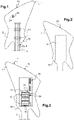
- a musical instrument according to the invention as illustrated in figure 1 and designated as a whole by the reference 1, comprises a body 2 with, in the present case, a neck 3 on which strings 4 located at a distance and parallel to the front face 5 of the body 2 of the instrument are held in tension 1.
- the front face 5 corresponds to the surface of the body 2 on which the strings 4 are anchored via, for example, a bridge fixed to the front face 5.
- the front face 5 can be the soundboard of the instrument of music 1.
- the musical instrument 1 with plucked or bowed strings, in accordance with the invention may not include a soundboard, as is the case for an instrument composed mainly of a body 2 bearing strings 4.
- the invention aims to propose means making it possible to easily interchange electrical or electronic systems for capturing the vibrations of the strings 4.
- the instrument is equipped with a device 10 for interchanging the systems 11 for capturing the vibrations of the strings. strings 4.
- the musical instrument 1 comprises a hatch 6 on the rear face 7, opposite the front face 5, so as to set up and connect the device 10 under the front face 5.
- the device 10 comprises in particular a cradle 13 fixed or integrated into the front face 5 and provided with electrical connection means 14 to an amplification circuit 15, of which only the outputs are shown.
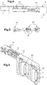
- the cradle 13, according to the example illustrated in particular visible at figure 6 is a partially worked metal structure comprising two housings that can accommodate two barrels 20.
- the example illustrated corresponds to a device 10 comprising two barrels 20 (described below) which respectively carry three capture systems 11.
- the two barrels 20 rotate along the axes A1 and A2 respectively, which are substantially parallel to each other and to the front face 5.
- the rotation of the barrels 20 makes it possible to present different systems 11 for capturing vibrations opposite the strings 4.
- the device 10 comprises means for maneuvering in rotation 21 of the barrels 20.
- These means for maneuvering in rotation 21 comprise a belt drive system 23 actuated, on the one hand by two levers 24 allowing the respective initiation and stopping of the rotation of the barrels 20 and on the other hand by a motor integrated into the cradle 13.
- the electric or electronic systems 11 for capturing the vibrations of the strings 4 of a musical instrument 1 can be guitar microphones electric. According to the example illustrated, these systems 11 comprise transducers 31 arranged in a row along an axis substantially parallel to the axis of rotation of the barrel 20.
- the transducers 31 convert the vibration of the metal strings 4 into an electrical signal.
- the transducers 31 can be composed of one or more magnets, surrounded by a coil of copper wire. Each magnet generates a magnetic field. By vibrating, the strings 4, which are spun in magnetic material, cause the magnetic circuit to vary slightly, which induces an electromotive force in the coil, proportional to the speed of movement of the string 4.
- the electrical signal produced is, for example , sent by wiring to the amplification circuit 15. It was not necessary to produce a sound to constitute it.
- pick-up systems 11 there are different pick-up systems 11, in particular those with single coils (which include a row of transducers 31) and those with double coils (including two parallel rows of transducers 31).
- the two barrels 20 carry systems 11 for picking up single coils.
- a double coil pick-up system 11, visible at the figure 10 is also suitable for a cylinder 20 according to the invention.
- the figure 7 illustrates a barrel 20, according to an embodiment where the barrel 20 carries three systems 11 of capture.
- the barrel 20 is a rotary device having substantially a cylindrical shape, it comprises a central part 32, visible at the figure 8 .
- This piece 32 has substantially the shape of a prism, it comprises three housings 33 (here for each face of the prism) designed to each carry a drawer 34 respectively.
- figure 9 illustrates a drawer 34 according to the invention. And, each drawer 34 is intended to accommodate a system 11 of capture.
- the electrical connection means 40 of the capture systems 11 to the rest of the electronics comprise a system of beryllium copper contactors.
- the central part 32 comprises three housings 33 and each of its housings 33 has two orifices 42 substantially in the shape of a bulb which make it possible to accommodate a drawer 34.
- the central part 32 of the barrel 20 then carries the electrical connection means 40 and therefore provides the link between the systems 11 and the connection means 14.
- One of the orifices 42 is able to connect the capture system 11 to the circuit, the 'other orifice 42 is able to connect it to ground.
- Each drawer 34 is immobilized on the central part 32 via the orifices 42 and in support by its rear face on the central part 32.
- the central part 32 is traversed by a cylindrical part 43 partially made of copper which provides the ground connection.
- the central part 32 of the barrel 20 comprises three outputs 44, to the connection means 14, each corresponding to a system 11 of capture.
- connection means 14 During rotation, only the cylindrical part 43 is in contact with the connection means 14. Therefore, no signal coming from the barrel 20 is transmitted to the rest of the electronics. When the rotation stops and a system 11 is in the working position, the contactors are again facing each other and the signal is transmitted to the connection means 14.
- the device further comprises means for indexing and immobilizing in rotation 45 the cylinder 20.
- these means 45 comprise two levers 24 which initiate the movement and stop the rotation of the barrel 20 in the working position, according to the system 11 chosen.
- a device 10 according to the invention may comprise more than two barrels 20 to obtain a capture of the vibrations of the strings 4 at more numerous places.
- a barrel of a device according to the invention can carry four capture systems 11 or even more, to offer a greater variety of systems 11.
- the cradle 13 can be designed differently to adapt to a new structure .
- the cylinder maneuvering means comprise a belt system.
- the barrel 20 can be rotated manually, that is to say that the outer surface of the barrel 20 then constitutes the means for maneuvering the latter. The musician then maneuvers the barrel 20 with one of his fingers by acting on the outer surface and thus changes the system 11 of capture.
- a cleat system could stop the rotation of the barrel 20, said cleat not resisting a some manual pressure.
- These means 45 can also comprise push buttons, knobs, rotating buttons or any other means making it possible to choose the capture system 11 which will be placed in the working position.
Landscapes
- Physics & Mathematics (AREA)
- Engineering & Computer Science (AREA)
- Acoustics & Sound (AREA)
- Multimedia (AREA)
- Electrophonic Musical Instruments (AREA)
- Stringed Musical Instruments (AREA)
Claims (13)
- Vorrichtung (10) zum Austausch von elektrischen oder elektronischen Systemen (11) zur Erfassung von Schwingungen der Saiten (4) eines Musikinstruments (1) mit einer auf die Saiten (4) gerichteten Vorderseite (5), wobei die Vorrichtung (10)- einen Träger (13), der dazu bestimmt ist, auf der Vorderseite (5) befestigt oder in diese integriert zu werden, und mit elektrischen Mitteln (14) zum Anschließen an einen Verstärkerkreis (15) versehen ist,- wenigstens einen Zylinder (20), der mit wenigstens zwei Erfassungssystemen (11) versehen ist, der auf dem Träger (13) so angebracht ist, daß er gegenüber dem Träger (13) zwischen wenigstens zwei Positionen drehbar ist, um in jeder Position ein Erfassungssystem (11) in Arbeitsposition gegenüber den Saiten (4) anzuordnen, und der Mittel zum elektrischen Verbinden (40) wenigstens des den Saiten (4) gegenüberliegenden Erfassungssystems (11) mit den Anschlußmitteln (14) aufweist,- Mittel (21) zum drehenden Betätigen des Zylinders (20)aufweist,
dadurch gekennzeichnet, daß die Drehachse A1 des Zylinders (20) im Wesentlichen parallel zur Vorderseite (5) ist, wenn der Träger (13) auf letzterer (5) befestigt ist. - Vorrichtung (10) gemäß Anspruch 1, dadurch gekennzeichnet, daß sie- wenigstens zwei Zylinder (20) aufweist, wobei jeder Zylinder (20) mit wenigstens zwei Erfassungssystemen (11) versehen ist, auf dem Träger (13) so angebracht ist, daß er gegenüber dem Träger (13) zwischen wenigstens zwei Positionen drehbar ist, um in jeder Position ein Erfassungssystem (11) in Arbeitsposition gegenüber den Saiten (4) anzuordnen, und Mittel zum elektrischen Verbinden (40) wenigstens des den Saiten (4) gegenüberliegenden Erfassungssystems (11) mit den Anschlußmitteln (14) aufweist,- Mittel (21) zum drehenden Betätigen des Zylinders (20) aufweist.
- Vorrichtung (10) gemäß Anspruch 1 oder 2, dadurch gekennzeichnet, daß jeder Zylinder (20) auf dem Träger (13) abnehmbar angebracht ist.
- Vorrichtung (10) gemäß einem der Ansprüche 1 bis 3, dadurch gekennzeichnet, daß jeder Zylinder (20) wenigstens eine Aufnahme (33) aufweist, die dazu bestimmt ist, einen ein Erfassungssystem (11) enthaltenden herausnehmbaren Einschub (34) aufzunehmen.
- Vorrichtung (10) gemäß Anspruch 4, dadurch gekennzeichnet, daß jedes Erfassungssystem (11) von einem herausnehmbaren Einschub (34) getragen ist und daß jeder Zylinder (20) so viel Aufnahmen (33) wie Erfassungssysteme (11) aufweist.
- Vorrichtung (10) gemäß einem der Ansprüche 1 bis 5, dadurch gekennzeichnet, daß jedes Erfassungssystem (11) eine Reihe Wandler (31) aufweist, die in einer zur Drehachse A1 des Zylinders (20) im Wesentlichen parallelen Richtung D1 ausgerichtet sind.
- Vorrichtung (10) gemäß einem der Ansprüche 1 bis 6, dadurch gekennzeichnet, daß sie Mittel (45) zur Indizierung und Verdrehsicherung jedes Zylinders (20) in jeder der Positionen, in der ein Erfassungssystem (11) in Arbeitsposition ist, aufweist.
- Vorrichtung (10) gemäß einem der Ansprüche 1 bis 7, dadurch gekennzeichnet, daß die Verbindungsmittel (40) so ausgelegt sind, daß nur das in Arbeitsposition befindliche Erfassungssystem (11) elektrisch mit den Anschlußmitteln (14) verbunden wird.
- Vorrichtung (10) gemäß einem der Ansprüche 1 bis 8, dadurch gekennzeichnet, daß die Betätigungsmittel (21) jedes Zylinders (20) motorisiert sind.
- Saiteninstrument (1) mit einer Vorderseite (5) und wenigstens einer Vorrichtung (10) gemäß einem der Ansprüche 1 bis 9, die so auf der Vorderseite (5) angebracht oder in diese integriert ist, daß jedes Erfassungssystem (11) in der Arbeitsposition gegenüber den Saiten (4) angeordnet ist.
- Instrument (1) gemäß Anspruch 10, dadurch gekennzeichnet, daß es eine elektrische Gitarre (1) ist.
- Einschub (34) mit wenigstens einem elektrischen oder elektronischen System (11) zur Erfassung von Schwingungen der Saiten (4) eines Musikinstruments (1), dadurch gekennzeichnet, daß er dazu bestimmt ist, an einem Zylinder (20) einer Vorrichtung (10) gemäß Anspruch 4 oder 5 abnehmbar angebracht zu werden.
- Zylinder (20) mit wenigstens zwei elektrischen oder elektronischen Systemen (11) zur Erfassung von Schwingungen der Saiten (4) eines Musikinstruments (1), dadurch gekennzeichnet, daß er dazu bestimmt ist, an einer Vorrichtung (10) gemäß einem der Ansprüche 1 bis 9 angebracht zu werden.
Applications Claiming Priority (2)
| Application Number | Priority Date | Filing Date | Title |
|---|---|---|---|
| FR1852882A FR3079655B1 (fr) | 2018-04-03 | 2018-04-03 | Dispositif pour interchanger des systemes electriques ou electroniques de captation des vibrations des cordes d'un instrument de musique |
| PCT/FR2019/050717 WO2019193268A1 (fr) | 2018-04-03 | 2019-03-28 | Dispositif pour interchanger des systemes electriques ou electroniques de captation des vibrations des cordes d'un instrument de musique |
Publications (2)
| Publication Number | Publication Date |
|---|---|
| EP3776525A1 EP3776525A1 (de) | 2021-02-17 |
| EP3776525B1 true EP3776525B1 (de) | 2022-06-15 |
Family
ID=63683961
Family Applications (1)
| Application Number | Title | Priority Date | Filing Date |
|---|---|---|---|
| EP19719559.7A Active EP3776525B1 (de) | 2018-04-03 | 2019-03-28 | Vorrichtung zum austausch von elektrischen oder elektronischen systemen zur erfassung von schwingungen der saiten eines musikinstruments |
Country Status (9)
| Country | Link |
|---|---|
| US (1) | US11393441B2 (de) |
| EP (1) | EP3776525B1 (de) |
| JP (1) | JP7225371B2 (de) |
| KR (1) | KR102706200B1 (de) |
| CN (1) | CN112088401B (de) |
| CA (1) | CA3096191A1 (de) |
| FR (1) | FR3079655B1 (de) |
| MX (1) | MX2020010345A (de) |
| WO (1) | WO2019193268A1 (de) |
Families Citing this family (2)
| Publication number | Priority date | Publication date | Assignee | Title |
|---|---|---|---|---|
| FR3079655B1 (fr) * | 2018-04-03 | 2020-03-27 | Wild Customs | Dispositif pour interchanger des systemes electriques ou electroniques de captation des vibrations des cordes d'un instrument de musique |
| US20220230606A1 (en) * | 2019-05-16 | 2022-07-21 | Matthew Schiebold | Non-Amorphous Musical Instrument Components |
Family Cites Families (42)
| Publication number | Priority date | Publication date | Assignee | Title |
|---|---|---|---|---|
| US611184A (en) * | 1898-09-20 | ra iney | ||
| US2207341A (en) * | 1937-06-01 | 1940-07-09 | Arthur B Mcmahan | Electrically amplified controlled stringed musical instrument |
| US2976755A (en) * | 1959-01-06 | 1961-03-28 | Clarence L Fender | Electromagnetic pickup for lute-type musical instrument |
| JPS57200096A (en) * | 1981-06-03 | 1982-12-08 | Nippon Musical Instruments Mfg | Electric guitar |
| US4616548A (en) * | 1984-03-26 | 1986-10-14 | Anderson Arndt S | Guitar composed of high strength-to-weight ratio material |
| FR2664415B2 (fr) | 1987-06-12 | 1992-09-11 | Betticare Olivier | Micro interchangeable pour guitare electrique. |
| US4854210A (en) * | 1987-08-26 | 1989-08-08 | Palazzolo Nicholas P | Detachable electric guitar pick-up system |
| FR2638882A1 (fr) | 1988-11-04 | 1990-05-11 | Gaucher Dany | Guitare. micros, plaques d'electroniques et touches interchangeables |
| US5012716A (en) * | 1989-03-21 | 1991-05-07 | Dronge & Rapoport Inc. | Rotatable pick-up head for electric guitar |
| US5136918A (en) | 1991-01-16 | 1992-08-11 | Gibson Guitar Corp. | Guitar pickup switching system for selecting between and within two standard tonalities |
| JP3233659B2 (ja) * | 1991-08-14 | 2001-11-26 | 株式会社フェルナンデス | 弦振動持続装置を備えた電気弦楽器 |
| US5252777A (en) * | 1992-08-10 | 1993-10-12 | Michael J. Allen | Electric guitar with transducer cradles |
| EP0968496B1 (de) * | 1997-03-17 | 2002-06-05 | Boxer & Fürst AG | Tonabnehmerschaltvorrichtung fuer ein saiteninstrument sowie saiteninstrument |
| GB2324402A (en) | 1997-04-15 | 1998-10-21 | John Patrick Pipkin | A pick-up assembly |
| US6291758B1 (en) | 1998-01-28 | 2001-09-18 | Fender Musical Instruments Corporation | Pick-up for electric guitars |
| US6291759B1 (en) | 1998-01-28 | 2001-09-18 | Fender Musical Instruments Corporation | Pickup for electric guitars, and method of transducing the vibrations of guitar strings |
| US6111184A (en) * | 1998-01-30 | 2000-08-29 | E-Mu Systems, Inc. | Interchangeable pickup, electric stringed instrument and system for an electric stringed musical instrument |
| US7015390B1 (en) * | 2003-01-15 | 2006-03-21 | Rogers Wayne A | Triad pickup |
| US7060888B2 (en) * | 2003-12-04 | 2006-06-13 | Michael Sebastian Spalt | Movable stringed instrument pickup system |
| JP4497365B2 (ja) * | 2005-01-07 | 2010-07-07 | ローランド株式会社 | ピックアップ装置 |
| TWI298482B (en) * | 2005-04-28 | 2008-07-01 | Yamaha Corp | Stringed musical instrument, transducer for the same and its mounting structure on the same |
| US7105731B1 (en) * | 2005-05-02 | 2006-09-12 | Riedl James L | Low noise vibrating string transducer |
| JP4702188B2 (ja) * | 2006-06-12 | 2011-06-15 | ヤマハ株式会社 | 電気弦楽器 |
| CN100561573C (zh) | 2006-06-14 | 2009-11-18 | 林瑞荣 | 一种用于电吉他拾音器的控制开关 |
| US20080245217A1 (en) * | 2007-04-07 | 2008-10-09 | Bret Thomas Stewart | Nearly Closed Magnetic Flux Electromagnetic Transducer for Instrument Pickups |
| US20120312146A1 (en) * | 2011-06-11 | 2012-12-13 | Benjamin Randal Bekerman | Interface Adapter for Installation of a Standard Magnetic Pickup into an Acoustic Guitar Sound Hole |
| CN202434197U (zh) * | 2011-11-13 | 2012-09-12 | 李青青 | 一种可变换弦演奏和按键演奏的吉他 |
| ES1077183Y (es) | 2012-04-13 | 2012-09-10 | Torres Raul Teodoro Perea | Guitarra eléctrica con pastillas electromagnéticas intercambiables |
| US8907200B2 (en) * | 2012-04-23 | 2014-12-09 | Benjamin Randal Bekerman | Transducer assembly mounting kit with feedback reduction device for installation into the sound hole of an acoustic guitar |
| FR2994760B1 (fr) | 2012-08-24 | 2016-08-12 | Olivier Betticare | Guitare electrique equipee d'un dispositif de micro interchangeable |
| US9047852B2 (en) * | 2013-07-01 | 2015-06-02 | Michael John Canavan | Pole position sliding pickup system |
| US12020674B2 (en) * | 2014-07-23 | 2024-06-25 | Donald L. Baker | Electric stringed instrument using movable pickups and humbucking circuits |
| US9847080B2 (en) | 2015-06-26 | 2017-12-19 | Joseph Chapman | System and method for switching sound pickups in an electric guitar using a spin wheel arrangement |
| US9728175B2 (en) * | 2015-08-22 | 2017-08-08 | Andrew James Strassell | Interchangeable pickup system for an electric stringed musical instrument |
| CN106228962A (zh) | 2016-07-28 | 2016-12-14 | 武汉艾立卡电子有限公司 | 一种带无线发射功能的便携电吉他 |
| US10311851B1 (en) * | 2016-12-07 | 2019-06-04 | Mark A. Stadnyk | Reconfigurable electric guitar pickup hot-swap cartridge system |
| US10650795B2 (en) * | 2017-10-11 | 2020-05-12 | Duneland Labs, LLC | Magnetic pickup systems for stringed instruments |
| FR3079655B1 (fr) * | 2018-04-03 | 2020-03-27 | Wild Customs | Dispositif pour interchanger des systemes electriques ou electroniques de captation des vibrations des cordes d'un instrument de musique |
| US10861430B1 (en) * | 2018-10-15 | 2020-12-08 | JKR Guitars, LLC | Guitar apparatus for switching pickups |
| US11074898B1 (en) * | 2019-02-26 | 2021-07-27 | Frank Dale Boxberger | Stringed instrument with an interchangeable magnetic pickup system |
| CN110349560A (zh) * | 2019-08-09 | 2019-10-18 | 黑龙江伊瑷斯霹电子音响有限公司 | 一种拾音器可自由转换的电吉他 |
| US11195503B2 (en) * | 2020-03-30 | 2021-12-07 | Justin Richard Bruen | Magnetic pickup positioning mechanism for electric musical instruments |
-
2018
- 2018-04-03 FR FR1852882A patent/FR3079655B1/fr active Active
-
2019
- 2019-03-28 US US16/341,564 patent/US11393441B2/en active Active
- 2019-03-28 JP JP2021503212A patent/JP7225371B2/ja active Active
- 2019-03-28 KR KR1020207028335A patent/KR102706200B1/ko active Active
- 2019-03-28 MX MX2020010345A patent/MX2020010345A/es unknown
- 2019-03-28 CN CN201980029835.0A patent/CN112088401B/zh active Active
- 2019-03-28 EP EP19719559.7A patent/EP3776525B1/de active Active
- 2019-03-28 CA CA3096191A patent/CA3096191A1/fr active Pending
- 2019-03-28 WO PCT/FR2019/050717 patent/WO2019193268A1/fr not_active Ceased
Also Published As
| Publication number | Publication date |
|---|---|
| MX2020010345A (es) | 2021-01-08 |
| JP2021520524A (ja) | 2021-08-19 |
| FR3079655B1 (fr) | 2020-03-27 |
| JP7225371B2 (ja) | 2023-02-20 |
| KR20200138744A (ko) | 2020-12-10 |
| US11393441B2 (en) | 2022-07-19 |
| FR3079655A1 (fr) | 2019-10-04 |
| CN112088401A (zh) | 2020-12-15 |
| US20210327398A1 (en) | 2021-10-21 |
| EP3776525A1 (de) | 2021-02-17 |
| CN112088401B (zh) | 2025-01-07 |
| CA3096191A1 (fr) | 2019-10-10 |
| WO2019193268A1 (fr) | 2019-10-10 |
| KR102706200B1 (ko) | 2024-09-13 |
Similar Documents
| Publication | Publication Date | Title |
|---|---|---|
| EP3776525B1 (de) | Vorrichtung zum austausch von elektrischen oder elektronischen systemen zur erfassung von schwingungen der saiten eines musikinstruments | |
| CH642460A5 (fr) | Ensemble de captage pour un transducteur. | |
| EP0976101A1 (de) | Hybridvorrichtung mit oberflächigen kontakten und erzeugung von akustischen signalen und verfahren zur ihrer herstellung | |
| EP0123646A2 (de) | Kapazitive Kraftmessvorrichtung | |
| FR2668874A1 (fr) | Systeme a aimants permanents associes a un assemblage de bobines, et utilisation d'un tel systeme dans un haut-parleur ou dans un detecteur. | |
| FR2487502A1 (fr) | Tete de mesure pour le controle des dimensions lineaires de pieces mecaniques | |
| EP0599174A1 (de) | Mikromechanisch hergestellter Messaufnehmer | |
| EP1570275A1 (de) | Beschleunigungssensor mit vibrierenden schwingbalken | |
| EP0692923B1 (de) | Selektive Schallaufnahmevorrichtung für reflektierende und geräuschvolle Umgebung | |
| EP3874331A1 (de) | Oszillierendes gewicht mit variabler geometrie für einen uhrwerkmechanismus | |
| FR2466903A1 (fr) | Transducteur piezoelectrique reglable pour montre | |
| FR2803131A1 (fr) | Moteur et structure de fixation | |
| CH633888A5 (fr) | Dispositif de support pour transducteur. | |
| WO2004036495A1 (fr) | Transpondeur et outil pour la lecture et/ou l'ecriture de donnees dans le transpondeur | |
| WO2011147787A2 (fr) | Capteur de rotation inertiel a structure simple | |
| WO2000023778A1 (fr) | Detecteur de position a cellule de detection micro-usinee | |
| EP1685411A1 (de) | Nicht-starr-leiter-verbindungs-messsensor und herstellungsverfahren dafür | |
| EP0901052B1 (de) | Bank für elektrische Chronometer und Steuerbox dafür | |
| FR2461292A1 (fr) | Montre electronique extra-plate | |
| FR2486230A1 (fr) | Perfectionnements a un dispositif tachymetrique commande par un moteur electrique | |
| CH717297A2 (fr) | Dispositif de contrôle de fonctions d'une montre. | |
| EP3893063A1 (de) | Kontrollvorrichtung der funktionen einer armbanduhr | |
| EP1358662B1 (de) | Gesichertes dateneingabegerät | |
| EP1623874B1 (de) | Automatische Rückstelleinrichtung für einen Fahrtrichtungsanzeiger | |
| CH712680A2 (fr) | Module à mécanisme, mouvement et pièce d'horlogerie. |
Legal Events
| Date | Code | Title | Description |
|---|---|---|---|
| STAA | Information on the status of an ep patent application or granted ep patent |
Free format text: STATUS: UNKNOWN |
|
| STAA | Information on the status of an ep patent application or granted ep patent |
Free format text: STATUS: THE INTERNATIONAL PUBLICATION HAS BEEN MADE |
|
| PUAI | Public reference made under article 153(3) epc to a published international application that has entered the european phase |
Free format text: ORIGINAL CODE: 0009012 |
|
| STAA | Information on the status of an ep patent application or granted ep patent |
Free format text: STATUS: REQUEST FOR EXAMINATION WAS MADE |
|
| 17P | Request for examination filed |
Effective date: 20200930 |
|
| AK | Designated contracting states |
Kind code of ref document: A1 Designated state(s): AL AT BE BG CH CY CZ DE DK EE ES FI FR GB GR HR HU IE IS IT LI LT LU LV MC MK MT NL NO PL PT RO RS SE SI SK SM TR |
|
| AX | Request for extension of the european patent |
Extension state: BA ME |
|
| DAV | Request for validation of the european patent (deleted) | ||
| DAX | Request for extension of the european patent (deleted) | ||
| GRAP | Despatch of communication of intention to grant a patent |
Free format text: ORIGINAL CODE: EPIDOSNIGR1 |
|
| STAA | Information on the status of an ep patent application or granted ep patent |
Free format text: STATUS: GRANT OF PATENT IS INTENDED |
|
| INTG | Intention to grant announced |
Effective date: 20220105 |
|
| GRAS | Grant fee paid |
Free format text: ORIGINAL CODE: EPIDOSNIGR3 |
|
| GRAA | (expected) grant |
Free format text: ORIGINAL CODE: 0009210 |
|
| STAA | Information on the status of an ep patent application or granted ep patent |
Free format text: STATUS: THE PATENT HAS BEEN GRANTED |
|
| AK | Designated contracting states |
Kind code of ref document: B1 Designated state(s): AL AT BE BG CH CY CZ DE DK EE ES FI FR GB GR HR HU IE IS IT LI LT LU LV MC MK MT NL NO PL PT RO RS SE SI SK SM TR |
|
| REG | Reference to a national code |
Ref country code: CH Ref legal event code: EP Ref country code: GB Ref legal event code: FG4D Free format text: NOT ENGLISH |
|
| REG | Reference to a national code |
Ref country code: IE Ref legal event code: FG4D Free format text: LANGUAGE OF EP DOCUMENT: FRENCH |
|
| REG | Reference to a national code |
Ref country code: DE Ref legal event code: R096 Ref document number: 602019015921 Country of ref document: DE |
|
| REG | Reference to a national code |
Ref country code: AT Ref legal event code: REF Ref document number: 1498857 Country of ref document: AT Kind code of ref document: T Effective date: 20220715 |
|
| REG | Reference to a national code |
Ref country code: NL Ref legal event code: FP |
|
| REG | Reference to a national code |
Ref country code: LT Ref legal event code: MG9D |
|
| PG25 | Lapsed in a contracting state [announced via postgrant information from national office to epo] |
Ref country code: SE Free format text: LAPSE BECAUSE OF FAILURE TO SUBMIT A TRANSLATION OF THE DESCRIPTION OR TO PAY THE FEE WITHIN THE PRESCRIBED TIME-LIMIT Effective date: 20220615 Ref country code: NO Free format text: LAPSE BECAUSE OF FAILURE TO SUBMIT A TRANSLATION OF THE DESCRIPTION OR TO PAY THE FEE WITHIN THE PRESCRIBED TIME-LIMIT Effective date: 20220915 Ref country code: LT Free format text: LAPSE BECAUSE OF FAILURE TO SUBMIT A TRANSLATION OF THE DESCRIPTION OR TO PAY THE FEE WITHIN THE PRESCRIBED TIME-LIMIT Effective date: 20220615 Ref country code: HR Free format text: LAPSE BECAUSE OF FAILURE TO SUBMIT A TRANSLATION OF THE DESCRIPTION OR TO PAY THE FEE WITHIN THE PRESCRIBED TIME-LIMIT Effective date: 20220615 Ref country code: GR Free format text: LAPSE BECAUSE OF FAILURE TO SUBMIT A TRANSLATION OF THE DESCRIPTION OR TO PAY THE FEE WITHIN THE PRESCRIBED TIME-LIMIT Effective date: 20220916 Ref country code: FI Free format text: LAPSE BECAUSE OF FAILURE TO SUBMIT A TRANSLATION OF THE DESCRIPTION OR TO PAY THE FEE WITHIN THE PRESCRIBED TIME-LIMIT Effective date: 20220615 Ref country code: BG Free format text: LAPSE BECAUSE OF FAILURE TO SUBMIT A TRANSLATION OF THE DESCRIPTION OR TO PAY THE FEE WITHIN THE PRESCRIBED TIME-LIMIT Effective date: 20220915 |
|
| PG25 | Lapsed in a contracting state [announced via postgrant information from national office to epo] |
Ref country code: RS Free format text: LAPSE BECAUSE OF FAILURE TO SUBMIT A TRANSLATION OF THE DESCRIPTION OR TO PAY THE FEE WITHIN THE PRESCRIBED TIME-LIMIT Effective date: 20220615 Ref country code: LV Free format text: LAPSE BECAUSE OF FAILURE TO SUBMIT A TRANSLATION OF THE DESCRIPTION OR TO PAY THE FEE WITHIN THE PRESCRIBED TIME-LIMIT Effective date: 20220615 |
|
| PG25 | Lapsed in a contracting state [announced via postgrant information from national office to epo] |
Ref country code: SM Free format text: LAPSE BECAUSE OF FAILURE TO SUBMIT A TRANSLATION OF THE DESCRIPTION OR TO PAY THE FEE WITHIN THE PRESCRIBED TIME-LIMIT Effective date: 20220615 Ref country code: SK Free format text: LAPSE BECAUSE OF FAILURE TO SUBMIT A TRANSLATION OF THE DESCRIPTION OR TO PAY THE FEE WITHIN THE PRESCRIBED TIME-LIMIT Effective date: 20220615 Ref country code: RO Free format text: LAPSE BECAUSE OF FAILURE TO SUBMIT A TRANSLATION OF THE DESCRIPTION OR TO PAY THE FEE WITHIN THE PRESCRIBED TIME-LIMIT Effective date: 20220615 Ref country code: PT Free format text: LAPSE BECAUSE OF FAILURE TO SUBMIT A TRANSLATION OF THE DESCRIPTION OR TO PAY THE FEE WITHIN THE PRESCRIBED TIME-LIMIT Effective date: 20221017 Ref country code: ES Free format text: LAPSE BECAUSE OF FAILURE TO SUBMIT A TRANSLATION OF THE DESCRIPTION OR TO PAY THE FEE WITHIN THE PRESCRIBED TIME-LIMIT Effective date: 20220615 Ref country code: EE Free format text: LAPSE BECAUSE OF FAILURE TO SUBMIT A TRANSLATION OF THE DESCRIPTION OR TO PAY THE FEE WITHIN THE PRESCRIBED TIME-LIMIT Effective date: 20220615 |
|
| PG25 | Lapsed in a contracting state [announced via postgrant information from national office to epo] |
Ref country code: PL Free format text: LAPSE BECAUSE OF FAILURE TO SUBMIT A TRANSLATION OF THE DESCRIPTION OR TO PAY THE FEE WITHIN THE PRESCRIBED TIME-LIMIT Effective date: 20220615 Ref country code: IS Free format text: LAPSE BECAUSE OF FAILURE TO SUBMIT A TRANSLATION OF THE DESCRIPTION OR TO PAY THE FEE WITHIN THE PRESCRIBED TIME-LIMIT Effective date: 20221015 |
|
| REG | Reference to a national code |
Ref country code: DE Ref legal event code: R097 Ref document number: 602019015921 Country of ref document: DE |
|
| PG25 | Lapsed in a contracting state [announced via postgrant information from national office to epo] |
Ref country code: AL Free format text: LAPSE BECAUSE OF FAILURE TO SUBMIT A TRANSLATION OF THE DESCRIPTION OR TO PAY THE FEE WITHIN THE PRESCRIBED TIME-LIMIT Effective date: 20220615 |
|
| PLBE | No opposition filed within time limit |
Free format text: ORIGINAL CODE: 0009261 |
|
| STAA | Information on the status of an ep patent application or granted ep patent |
Free format text: STATUS: NO OPPOSITION FILED WITHIN TIME LIMIT |
|
| PG25 | Lapsed in a contracting state [announced via postgrant information from national office to epo] |
Ref country code: DK Free format text: LAPSE BECAUSE OF FAILURE TO SUBMIT A TRANSLATION OF THE DESCRIPTION OR TO PAY THE FEE WITHIN THE PRESCRIBED TIME-LIMIT Effective date: 20220615 |
|
| 26N | No opposition filed |
Effective date: 20230316 |
|
| PG25 | Lapsed in a contracting state [announced via postgrant information from national office to epo] |
Ref country code: SI Free format text: LAPSE BECAUSE OF FAILURE TO SUBMIT A TRANSLATION OF THE DESCRIPTION OR TO PAY THE FEE WITHIN THE PRESCRIBED TIME-LIMIT Effective date: 20220615 |
|
| REG | Reference to a national code |
Ref country code: IE Ref legal event code: MM4A |
|
| PG25 | Lapsed in a contracting state [announced via postgrant information from national office to epo] |
Ref country code: IE Free format text: LAPSE BECAUSE OF NON-PAYMENT OF DUE FEES Effective date: 20230328 |
|
| REG | Reference to a national code |
Ref country code: LU Ref legal event code: PD Owner name: ORFIM; FR Free format text: FORMER OWNER: WILD CUSTOMS Effective date: 20240703 |
|
| REG | Reference to a national code |
Ref country code: GB Ref legal event code: 732E Free format text: REGISTERED BETWEEN 20240711 AND 20240717 |
|
| REG | Reference to a national code |
Ref country code: AT Ref legal event code: UEP Ref document number: 1498857 Country of ref document: AT Kind code of ref document: T Effective date: 20220615 |
|
| PG25 | Lapsed in a contracting state [announced via postgrant information from national office to epo] |
Ref country code: BG Free format text: LAPSE BECAUSE OF FAILURE TO SUBMIT A TRANSLATION OF THE DESCRIPTION OR TO PAY THE FEE WITHIN THE PRESCRIBED TIME-LIMIT Effective date: 20220615 |
|
| PG25 | Lapsed in a contracting state [announced via postgrant information from national office to epo] |
Ref country code: BG Free format text: LAPSE BECAUSE OF FAILURE TO SUBMIT A TRANSLATION OF THE DESCRIPTION OR TO PAY THE FEE WITHIN THE PRESCRIBED TIME-LIMIT Effective date: 20220615 |
|
| PGFP | Annual fee paid to national office [announced via postgrant information from national office to epo] |
Ref country code: LU Payment date: 20250220 Year of fee payment: 7 |
|
| PGFP | Annual fee paid to national office [announced via postgrant information from national office to epo] |
Ref country code: MC Payment date: 20250312 Year of fee payment: 7 |
|
| PGFP | Annual fee paid to national office [announced via postgrant information from national office to epo] |
Ref country code: DE Payment date: 20250221 Year of fee payment: 7 |
|
| PGFP | Annual fee paid to national office [announced via postgrant information from national office to epo] |
Ref country code: NL Payment date: 20250319 Year of fee payment: 7 |
|
| PGFP | Annual fee paid to national office [announced via postgrant information from national office to epo] |
Ref country code: AT Payment date: 20250221 Year of fee payment: 7 Ref country code: BE Payment date: 20250220 Year of fee payment: 7 |
|
| PGFP | Annual fee paid to national office [announced via postgrant information from national office to epo] |
Ref country code: FR Payment date: 20250220 Year of fee payment: 7 Ref country code: CZ Payment date: 20250325 Year of fee payment: 7 |
|
| PGFP | Annual fee paid to national office [announced via postgrant information from national office to epo] |
Ref country code: IT Payment date: 20250306 Year of fee payment: 7 Ref country code: GB Payment date: 20250220 Year of fee payment: 7 |
|
| PGFP | Annual fee paid to national office [announced via postgrant information from national office to epo] |
Ref country code: CH Payment date: 20250401 Year of fee payment: 7 |
|
| PG25 | Lapsed in a contracting state [announced via postgrant information from national office to epo] |
Ref country code: CY Free format text: LAPSE BECAUSE OF FAILURE TO SUBMIT A TRANSLATION OF THE DESCRIPTION OR TO PAY THE FEE WITHIN THE PRESCRIBED TIME-LIMIT; INVALID AB INITIO Effective date: 20190328 |
|
| PG25 | Lapsed in a contracting state [announced via postgrant information from national office to epo] |
Ref country code: HU Free format text: LAPSE BECAUSE OF FAILURE TO SUBMIT A TRANSLATION OF THE DESCRIPTION OR TO PAY THE FEE WITHIN THE PRESCRIBED TIME-LIMIT; INVALID AB INITIO Effective date: 20190328 |
|
| PG25 | Lapsed in a contracting state [announced via postgrant information from national office to epo] |
Ref country code: TR Free format text: LAPSE BECAUSE OF FAILURE TO SUBMIT A TRANSLATION OF THE DESCRIPTION OR TO PAY THE FEE WITHIN THE PRESCRIBED TIME-LIMIT Effective date: 20220615 |