EP3775937B1 - Constructive system regarding a capacitive sensor - Google Patents
Constructive system regarding a capacitive sensor Download PDFInfo
- Publication number
- EP3775937B1 EP3775937B1 EP19719626.4A EP19719626A EP3775937B1 EP 3775937 B1 EP3775937 B1 EP 3775937B1 EP 19719626 A EP19719626 A EP 19719626A EP 3775937 B1 EP3775937 B1 EP 3775937B1
- Authority
- EP
- European Patent Office
- Prior art keywords
- electrode
- fact
- elements
- construction system
- electric field
- Prior art date
- Legal status (The legal status is an assumption and is not a legal conclusion. Google has not performed a legal analysis and makes no representation as to the accuracy of the status listed.)
- Active
Links
Images



Classifications
-
- G—PHYSICS
- G01—MEASURING; TESTING
- G01R—MEASURING ELECTRIC VARIABLES; MEASURING MAGNETIC VARIABLES
- G01R15/00—Details of measuring arrangements of the types provided for in groups G01R17/00 - G01R29/00, G01R33/00 - G01R33/26 or G01R35/00
- G01R15/04—Voltage dividers
- G01R15/06—Voltage dividers having reactive components, e.g. capacitive transformer
-
- G—PHYSICS
- G01—MEASURING; TESTING
- G01R—MEASURING ELECTRIC VARIABLES; MEASURING MAGNETIC VARIABLES
- G01R15/00—Details of measuring arrangements of the types provided for in groups G01R17/00 - G01R29/00, G01R33/00 - G01R33/26 or G01R35/00
- G01R15/14—Adaptations providing voltage or current isolation, e.g. for high-voltage or high-current networks
- G01R15/16—Adaptations providing voltage or current isolation, e.g. for high-voltage or high-current networks using capacitive devices
-
- G—PHYSICS
- G01—MEASURING; TESTING
- G01R—MEASURING ELECTRIC VARIABLES; MEASURING MAGNETIC VARIABLES
- G01R15/00—Details of measuring arrangements of the types provided for in groups G01R17/00 - G01R29/00, G01R33/00 - G01R33/26 or G01R35/00
- G01R15/14—Adaptations providing voltage or current isolation, e.g. for high-voltage or high-current networks
- G01R15/16—Adaptations providing voltage or current isolation, e.g. for high-voltage or high-current networks using capacitive devices
- G01R15/165—Adaptations providing voltage or current isolation, e.g. for high-voltage or high-current networks using capacitive devices measuring electrostatic potential, e.g. with electrostatic voltmeters or electrometers, when the design of the sensor is essential
-
- G—PHYSICS
- G01—MEASURING; TESTING
- G01R—MEASURING ELECTRIC VARIABLES; MEASURING MAGNETIC VARIABLES
- G01R19/00—Arrangements for measuring currents or voltages or for indicating presence or sign thereof
- G01R19/0084—Measuring voltage only
-
- G—PHYSICS
- G01—MEASURING; TESTING
- G01R—MEASURING ELECTRIC VARIABLES; MEASURING MAGNETIC VARIABLES
- G01R15/00—Details of measuring arrangements of the types provided for in groups G01R17/00 - G01R29/00, G01R33/00 - G01R33/26 or G01R35/00
- G01R15/14—Adaptations providing voltage or current isolation, e.g. for high-voltage or high-current networks
- G01R15/142—Arrangements for simultaneous measurements of several parameters employing techniques covered by groups G01R15/14 - G01R15/26
Definitions
- the present invention relates to a constructive system regarding a capacitive voltage sensor, wherein said sensor is able to detect the electric field generated by a voltage element of the same capacitive sensor, in order, for example, to be able to estimate the value of the voltage of said live element.
- the present invention relates to a constructive system regarding a capacitive voltage sensor, wherein said sensor provides for detecting the electric field generated by the voltage element of the same sensor without undergoing the influence of any surrounding electric and/or magnetic fields, such as, for example, electro/magnetic fields generated by other conductors and/or other bars arranged nearby.
- EP 3,002,594 discloses a voltage sensing device. According to the abstract of this document, there is provided a voltage sensing device for a high and/or medium voltage power carrying conductor, the voltage sensing device comprising: - a radially outer electrode operable as a first sensing electrode of a sensing capacitor for sensing the voltage of the power carrying conductor; - a radially inner electrode operable as a second sensing electrode of the sensing capacitor; - a dielectric material arranged between the inner and the outer electrode, wherein the coefficient of thermal expansion of the material of at least one electrode is selected such that it compensates the temperature dependent parameters of the dielectric material and/or the other electrode, that influences the capacity of the voltage sensing capacitor.
- a first drawback is due to the fact that the resin dielectric material arranged around the components of the sensor includes vacuoles (air bubbles) with consequent phenomena of undesired partial discharges.
- a second drawback is due to the fact that the same resin is detached with respect to the elements that make up the capacitive sensor with consequent phenomena of undesired partial discharges.
- _A fourth drawback is due to the fact that the components that make up the sensors are expensive to make.
- the purpose of the present invention is therefore to solve the aforementioned drawbacks.
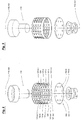
- the constructive system of the present invention concerns a capacitive electric voltage sensor, indicated with S.100 in Figs. 1 , 2 and 3 , and with S.200 in Figs. 4 , 5 and 6 , in which said system extends axially along an axis Y_S.100 / Y_S.200, defined longitudinal, configuring a first axial end portion, Ya_S.100 / Ya_S.200, here defined for descriptive reasons as vicinal without limiting intent, and a second axial end portion, Yb_S.100 / Yb_S.200 , here defined for descriptive reasons as distal without limiting intent, in which said sensor extends transversely along a transverse axis X .
- Said system substantially comprises: a first electrode 110/210 (made completely or partially with conductive material as better understood in the following), a second electrode 120/220 (made completely or partially with conductive material as better understood later), and a mass of dielectric insulating material, 130/230 .
- the first electrode 110 / 210 is positioned near said first axial end portion Ya_S.100 / Ya_S.200 and preferably has an elongated shape which extends axially along its axis Y_110 / Y_210 arranged coaxially with respect to the axis Y_S.100 / Y_S.200 of the sensor S.100 / S.200 , in order to configure a first axial portion 110.v / 210.v defined vicinal and a second axial portion 110.d / 210.d defined distal and opposite with respect to the first axial portion 110.v / 210.d .
- the second electrode 120 / 220 has a tubular shape that extends longitudinally along a longitudinal axis thereof Y_120 / Y_220 arranged coaxially with respect to the axis of the sensor Y_S.100 / Y_S.200 of the sensor S.100 / S.200 .
- said second electrode 120/220 is positioned around said first electrode 110 / 210 , more particularly around the distal portion 110.d / 210.d of said first electrode 110 / 210 , and also said second electrode 120 / 220 configures a first axial portion 120.v / 220.v defined vicinal and a second axial portion 120.d / 220.d defined distal which is opposite with respect to said first axial portion 120.v / 220.v.
- dielectric insulating material 130 / 230 With reference to the mass of dielectric insulating material 130 / 230 it is intended to at least partially enclose said first electrode 110 / 210 and said second electrode 120 / 220 .
- the aforementioned first electrode 110 / 210 preferably has a funnel-like shape, with its distal portion 100.d / 210.d lying within the vicinal portion 120.v / 220.v of the tutelar body defined by the second electrode 120 / 220 .
- the second electrode 120 / 220 it comprises a plurality of first elements, 121a, 121b, 121c, etc. / 221a / 221b, 221c , etc., which have an axially elongated shape intended to define for each of them a vicinal axial end, 121a.v / 221a.v , and a distal axial end 121a.d / 221a.d.
- first elements 121a, 121b, etc. / 221a, 221b, etc. are arranged circumferentially side by side with each other, in order to configure a tubular body 120 / 220 and, again these first elements 121a, 121b, etc. / 221a / 221b, etc.
- the system of the present invention can further comprise a second element 150 / 250 , wherein said second element 150 / 250 is positioned near the distal ends 121a.d, 121b.d, etc. / 221a.d, 221b.d, etc. of said plurality of first elements 121a, 121b, etc. / 221a, 221b, etc. , as for example inside the circular ring 123 / 223 which acts as a support foot.
- said first elements 121a, 121b, etc. / 221a / 221b, etc. are circumferentially spaced apart, in order to form openings 122a, 122b, etc. / 222a, 222b, etc. , in which said openings have a width such as to allow the resin, in its liquid/pasty state, and therefore during the pouring thereof, to flow between said openings 122a, 122b, etc. / 222a, 222b, etc. from the outside towards the inside of the tubular body 120 / 220 as well as from the inside towards the outside of the same tubular body 120 / 220 and, therefore, allowing to the same resin to perfectly arrange itself around the individual elements.
- said first elements 121a, 121b, etc. / 221a, 221b, etc. can also be equipped with through holes 124/224.
- said first elements 121a, 121b, etc. / 221a, 221b, etc. can be laminar elements having an elongated shape which extends along a respective longitudinal axis 121a.y / 221a.y, in which the latter axis can be oriented parallel to the longitudinal axis Y_S.100 / Y_S.200 of the sensor S. 100 / S.200.
- this parallelism is a preferred but not a limiting characteristic and, therefore, also other embodiments in which this parallelism is not present are protected by the present invention.
- the distal ends 121a.d, 121b.d, etc. / 221a.d, 221b.d, etc. of said first elements 121a, 121b, etc. / 221a / 221b, etc. are associated/constrained to the external perimeter 151 / 2510f said second element 150 / 250, and said second element 150 / 250 is preferably provided with through openings 154a, 153b / 253a, 253b, near the external perimeter 151 / 251 (having a shape in the form of a half-moon) or within said external perimeter 151 / 251, for the same reasons as previously indicated with respect to the openings 124 / 224.
- said second electrode 120 / 220 having a tubular shape and said second element 150 / 250 having a disc-like shape can form an electrode having the shape of a "glass/cup", in which said first elements 121a, 121b, etc. / 221a / 221b, etc. form the tubular portion of said glass and in which the second element 150 / 250 forms the bottom portion of the same glass.
- the first electrode 110 is connected to a voltage potential, such as for example a live bar by a conductive connection, in such a way that said first electrode 110 performs the function of source electrode 110 electric field generator.
- the second electrode 120 positioned around said source electrode 110 , acts as an electric field sensor electrode 120 and, more particularly, as an electric field sensor electrode 120 able to detect the electric field generated by said source electrode 110 , wherein also the second element 150 is present, wherein said second element 150 can also act as an electric field sensor.
- the second electrode 120 is connected to a voltage potential, such as for example a live bar by a conductive connection, so that said second electrode 120 performs the function of source electrode 120 electric field generator.
- the first electrode 110 positioned within said second source electrode 120 , acts as an electric field sensor electrode 110 and, more particularly, as an electric field sensor electrode 110 able to detect the electric field generated by said source electrode 120 .
- first elements 221a, 221b, 221c, etc. comprise respective first laminae 224 in insulating material designed to form a self-supporting support structure and respective first thin layers 225 of conductive material applied on the respective inner surfaces of said first laminae 224 , wherein the set of the various layers 225 made of conductive material of the various first elements 221a, 221b, 221c, etc. form the second electrode 220_225 having a tubular shape.
- said first elements 221a, 221b, 221c, etc. may further comprise respective second thin layers 226 of conductive material applied on the outer surface of said first sheets 224, electrically insulated with respect to the first thin layers 225 and preferably connected to ground, in which the set of the various layers 226 form an electromagnetic screen, having tubular form, which is adapted to prevent electric field lines external to the sensor S_200 , such as for example electric field lines generated by conductors arranged nearby, to close on the first internal electrode 210 or on the second electrode 220_225 , in such a way that the capacitive coupling between the first electrode 210 and the second electrode 220_225 is immune to the external electric fields.
- the set of the various layers 226 form an electromagnetic screen, having tubular form, which is adapted to prevent electric field lines external to the sensor S_200 , such as for example electric field lines generated by conductors arranged nearby, to close on the first internal electrode 210 or on the second electrode 220_225 , in such a way that the capacitive
- FIGS 4 , 5 , 6 , 7 and 8 they illustrate a variant embodiment of the system object of the present invention in which said second element 250 comprises a first lamina 254 made of insulating material stretched to form a self-supporting supporting structure and a first thin layer of conductive material 255 applied to the inner surface of said first lamina 254 , wherein said first thin layer 255 of conductive material is stretched to form a further component for second electrode 220 of the capacitive sensor S_200 , for example electrically connecting said layer inner/upper 255 with the first conductive inner layer 225 of the second electrode 220.
- said second element 250 may further comprise a second thin layer 256 of conductive material (preferably connected to ground) applied on the outer surface of said first lamina 254 and electrically insulated with respect to the first thin layer 255 , stretched to form an electromagnetic shield adapted to prevent to the electric field lines external to the sensor S_200 (such as for example electric field lines generated by conductors arranged nearby) to close on the first internal electrode 210 or on the second electrode 220_225 , so that the capacitive coupling between the first central electrode 210 and the second tubular electrode 210_225 is immune to external electric fields.
- a second thin layer 256 of conductive material preferably connected to ground
- FIG. 7 it illustrates a flat coppered base B1 which can be rolled up, comprising a base 223 and "petals" 221a, 221b, etc. , in which the said base B1 is able to form the second electrode 220 having a tubular shape.
- the flat base B1 comprises a first lamina 224 of insulating material intended to form a self-supporting support structure and a first thin layer 225 of conductive material applied on the inner surface of said first lamina 224 , in such a way that by wrapping said base in the manner of a ring with the first layer 225 inside the second electrode 220 is obtained.
- said base B1 may also comprise a second thin layer 226 of conductive material applied to the outer surface of said first lamina 224 , wherein said second thin layer 226 is electrically insulated with respect to the first thin layer 225 , in order to form, throughout the winding in the form of a ring as aforesaid, an electromagnetic shield having a tubular shape in relation to the second electrode 220 as specified above.
- the second element 250 can also be obtained by means of a copper-plated base B2 , comprising a first lamina 254 made of insulating material intended to form a self-supporting supporting structure and a first thin layer of conductive material 255 applied to the inner/upper surface of said first lamina 254 , in which said first thin layer 255 of conductive material is stretched to form a further component for the second electrode 220 as aforesaid.
- said second element 250 may further comprise a second thin layer 256 of conductive material applied to the outer/lower surface of said first lamina 254 , wherein said second layer 256 is electrically insulated with respect to the first layer 255 , as well as a third layer of conductive material 257 , applied on the outer/lower face of said lamina 254 , electrically isolated with respect to the second layer 256 , wherein said third layer 257 is connected by one or more "via" 258 with the first layer of inner and upper conductive material 255 .
- the capacitive sensor S_200 object of the present invention can provide a first and a second operative configuration.
- said first electrode 210 can act as a source electrode and the second electrode 220 , more particularly the inner conductive layer 225 (and also the optional inner conductive layer 255 of the second element 250 ) can perform the function of an electric field sensor electrode adapted to detect the electric field emitted by the first electrode 210 (225, 255) .
- said second electrode 220 can perform the function of an electric field source electrode and said first electrode 210 can act as an electric field sensor electrode able to detect the electric field emitted by the second electrode 220 (i.e. from the layer 225 and/or the layer 255 ).
Landscapes
- Physics & Mathematics (AREA)
- General Physics & Mathematics (AREA)
- Engineering & Computer Science (AREA)
- Power Engineering (AREA)
- Measuring Instrument Details And Bridges, And Automatic Balancing Devices (AREA)
- Investigating Or Analyzing Materials By The Use Of Electric Means (AREA)
- Measuring Fluid Pressure (AREA)
Priority Applications (1)
| Application Number | Priority Date | Filing Date | Title |
|---|---|---|---|
| PL19719626T PL3775937T3 (pl) | 2018-03-30 | 2019-03-19 | Układ konstrukcji dotyczący czujnika pojemnościowego |
Applications Claiming Priority (2)
| Application Number | Priority Date | Filing Date | Title |
|---|---|---|---|
| IT102018000004114A IT201800004114A1 (it) | 2018-03-30 | 2018-03-30 | Sistema costruttivo afferente un sensore capacitivo di tensione |
| PCT/IT2019/000023 WO2019186607A1 (en) | 2018-03-30 | 2019-03-19 | Constructive system regarding a capacitive sensor |
Publications (2)
| Publication Number | Publication Date |
|---|---|
| EP3775937A1 EP3775937A1 (en) | 2021-02-17 |
| EP3775937B1 true EP3775937B1 (en) | 2021-12-22 |
Family
ID=62816915
Family Applications (1)
| Application Number | Title | Priority Date | Filing Date |
|---|---|---|---|
| EP19719626.4A Active EP3775937B1 (en) | 2018-03-30 | 2019-03-19 | Constructive system regarding a capacitive sensor |
Country Status (5)
| Country | Link |
|---|---|
| US (4) | US11543436B2 (pl) |
| EP (1) | EP3775937B1 (pl) |
| IT (1) | IT201800004114A1 (pl) |
| PL (1) | PL3775937T3 (pl) |
| WO (1) | WO2019186607A1 (pl) |
Families Citing this family (11)
| Publication number | Priority date | Publication date | Assignee | Title |
|---|---|---|---|---|
| IT201600103234A1 (it) | 2016-10-14 | 2018-04-14 | Green Seas Ventures Ldt | Sistema Costruttivo afferente un sensore capacitivo di tensione |
| CN113227802B (zh) | 2018-12-17 | 2025-02-11 | G&W电气公司 | 电传感器组合件 |
| EP3899553A4 (en) | 2018-12-17 | 2022-10-26 | G & W Electric Company | ELECTRIC SENSOR ASSEMBLY |
| AT523120B1 (de) | 2019-11-14 | 2023-10-15 | Greenwood Power Gmbh | Spannungssensor und Spannungsteilungsvorrichtung |
| EP3882642A1 (en) * | 2020-03-17 | 2021-09-22 | 3M Innovative Properties Company | Sensored insulation plug |
| EP3913379A1 (en) | 2020-05-20 | 2021-11-24 | 3M Innovative Properties Company | Capacitor assembly |
| US12437924B2 (en) | 2020-10-01 | 2025-10-07 | 3M Innovative Properties Company | Dielectric material for a high voltage capacitor |
| EP3978936B1 (en) | 2020-10-01 | 2026-03-25 | 3M Innovative Properties Company | Sensored insulation plug |
| EP4001928B1 (en) | 2020-11-19 | 2025-06-25 | 3M Innovative Properties Company | Sensored insulation plug |
| EP4099024B1 (en) * | 2021-06-04 | 2025-03-19 | 3M Innovative Properties Company | Sensored insulation plug with detection contact |
| EP4123316B1 (en) | 2021-07-22 | 2025-06-25 | 3M Innovative Properties Company | Sensored bushing |
Family Cites Families (150)
| Publication number | Priority date | Publication date | Assignee | Title |
|---|---|---|---|---|
| GB967853A (en) | 1960-03-25 | 1964-08-26 | Reyrolle A & Co Ltd | Improvements relating to high-voltage insulation and insulating components |
| US3396339A (en) | 1963-11-29 | 1968-08-06 | Varian Associates | Capacitive voltage sensing device including coaxially disposed conductive tubes and electrical discharge inhibition means |
| DE2149881B1 (de) | 1971-10-06 | 1973-02-01 | Hartmann & Braun Ag | Kapazitiver geber |
| DE2215928B2 (de) * | 1972-03-29 | 1975-10-30 | Siemens Ag, 1000 Berlin Und 8000 Muenchen | Spannungs-Meßeinrichtung für eine vollisolierte, metallgekapselte Hochspannungs-Schaltanlage |
| US4268889A (en) * | 1978-05-31 | 1981-05-19 | Automatic Systems Laboratories Limited | Rotary displacement capacitive transducers |
| US4241373A (en) * | 1979-03-30 | 1980-12-23 | Mcgraw-Edison Company | Switchgear voltage sensor |
| US4700123A (en) | 1985-09-17 | 1987-10-13 | Sigma Instruments, Inc. | Power distribution systems and means for control thereof |
| GB2203557A (en) | 1987-04-09 | 1988-10-19 | Bonar Wallis Electronics Limit | Voltage sensing devices |
| US5136241A (en) | 1990-08-27 | 1992-08-04 | The United States Of America As Represented By The Secretary Of The Navy | Device for sensing unwanted electric and magnetic fields in a remote sensor electrical lead |
| DE4412642A1 (de) | 1994-04-13 | 1995-10-19 | Bosch Gmbh Robert | Kapazitiver Sensor zum Erfassen von Hochspannungssignalen |
| US5661240A (en) | 1995-09-25 | 1997-08-26 | Ford Motor Company | Sampled-data interface circuit for capacitive sensors |
| DE19613688A1 (de) | 1996-04-05 | 1997-10-09 | Habemus Electronic & Transfer | Meßeinrichtung für Niederspannungen |
| SE507933C2 (sv) | 1996-07-15 | 1998-07-27 | Asea Brown Boveri | Förfarande, anordning och sensor för att kapacitivt detektera fält och spänning samt användning därav |
| DE19713916B4 (de) * | 1997-04-04 | 2014-08-28 | Abb Schweiz Ag | Kapazitiver Spannungswandler für eine metallgekapselte, gasisolierte Hochspannungsanlage |
| US6307385B1 (en) | 1997-12-30 | 2001-10-23 | Vibrosystm, Inc. | Capacitance measuring circuit for a capacitive sensor |
| US6252388B1 (en) | 1998-12-04 | 2001-06-26 | Nxtphase Corporation | Method and apparatus for measuring voltage using electric field sensors |
| JP2001102817A (ja) | 1999-09-29 | 2001-04-13 | Nec Corp | 高周波回路及び該高周波回路を用いたシールディドループ型磁界検出器 |
| US6538422B2 (en) | 2000-04-26 | 2003-03-25 | S & C Electric Co. | Voltage sensor bushing assembly with integral capacitance screen |
| US6791334B2 (en) * | 2001-02-22 | 2004-09-14 | Denso Corporation | Oil condition sensor and method for making the same |
| US7293467B2 (en) | 2001-07-09 | 2007-11-13 | Nartron Corporation | Anti-entrapment system |
| WO2003050547A2 (en) | 2001-12-10 | 2003-06-19 | Bae Systems Information And Electronic Systems Integration Inc. | Electric field sensor |
| DE10303480A1 (de) | 2003-01-24 | 2004-08-05 | E.G.O. Elektro-Gerätebau GmbH | Schaltungsanordnung für einen kapazitiven Näherungsschalter |
| ES2221551B1 (es) | 2003-02-20 | 2006-02-16 | Industrias De Aparellaje Electrico,S.A. | Sensor de tension capacitivo para lineas de corriente alterna de alta tension. |
| EP1704417A1 (en) | 2004-01-07 | 2006-09-27 | Suparules Limited | Voltage measuring device |
| US7323886B2 (en) * | 2004-08-16 | 2008-01-29 | Ying Lau Lee | Linear capacitance measurement and touchless switch |
| JP4481806B2 (ja) * | 2004-12-03 | 2010-06-16 | アルプス電気株式会社 | 容量検出型センサ |
| EP1793497B1 (en) | 2005-12-02 | 2011-04-27 | STMicroelectronics Srl | Device and method for reading a capacitive sensor, in particular of a micro-electromechanical type |
| US7466146B2 (en) | 2006-03-10 | 2008-12-16 | Freescale Semiconductor, Inc. | Frozen material detection using electric field sensor |
| US10203814B2 (en) | 2006-04-20 | 2019-02-12 | Nokia Technologies Oy | Sensor arrangement comprising a conductive layer |
| GB0709893D0 (en) | 2007-05-23 | 2007-07-04 | Onzo Ltd | Apparatus for monitoring rescue consumption |
| JP4968121B2 (ja) | 2008-03-10 | 2012-07-04 | 富士通セミコンダクター株式会社 | 容量センサー |
| TWI317957B (en) | 2008-05-05 | 2009-12-01 | Generalplus Technology Inc | Capacitive sensor |
| CN101605292B (zh) | 2008-06-13 | 2013-04-24 | 清华大学 | 发声装置及发声元件 |
| ITBO20080392A1 (it) | 2008-06-20 | 2009-12-21 | Alberto Bauer | Sensore capacitivo per rilevare un campo elettrico generato da un conduttore |
| ITBO20080079U1 (it) | 2008-10-30 | 2010-04-30 | Lorenzo Peretto | Sistema costruttivo per un sensore capacitivo. |
| US10396785B2 (en) | 2017-12-12 | 2019-08-27 | Nxp Usa, Inc. | Reduction of capacitive touch sense electrode sample value change when electrode scan period is changed |
| US8225677B2 (en) | 2008-11-06 | 2012-07-24 | Northeastern University | Capacitive sensor, system, and method for measuring parameters of a two-phase flow |
| ITBO20080084U1 (it) | 2008-11-18 | 2010-05-19 | Lorenzo Peretto | Sistema costruttivo per sensore di corrente e/o di tensione elettrica |
| ITBO20080092U1 (it) * | 2008-12-15 | 2010-06-16 | Lorenzo Peretto | Sistema costruttivo per un sensore di tensione e/o di corrente elettrica. |
| US8163574B2 (en) | 2009-05-08 | 2012-04-24 | Eaton Corporaton | System and method for sensing voltage in medium-to-high voltage applications |
| WO2010132607A2 (en) | 2009-05-13 | 2010-11-18 | Synaptics Incorporated | Capacitive sensor device |
| DE102009059202A1 (de) | 2009-07-20 | 2011-02-03 | Huf Hülsbeck & Fürst Gmbh & Co. Kg | Sensormodul |
| EP2299285A1 (en) | 2009-09-18 | 2011-03-23 | ABB Technology AG | Capacitance meter, method, and computer program product for improved capacitance measurement |
| EP2317645B1 (en) | 2009-10-16 | 2013-04-10 | Nxp B.V. | Capacitive sensor |
| JP2013510445A (ja) | 2009-11-09 | 2013-03-21 | スリーエム イノベイティブ プロパティズ カンパニー | 半導体の異方性エッチングプロセス |
| US8294477B2 (en) * | 2009-11-20 | 2012-10-23 | Smc Electrical Products, Inc. | High voltage sensing capacitor and indicator device |
| TWI435088B (zh) | 2010-03-12 | 2014-04-21 | Nuvoton Technology Corp | 電容式感測器及感測方法 |
| US20110234311A1 (en) | 2010-03-25 | 2011-09-29 | Kabushiki Kaisha Toshiba | Current detection circuit and information terminal |
| WO2011125725A1 (ja) | 2010-03-31 | 2011-10-13 | 東海ゴム工業株式会社 | 静電容量型センサ装置および静電容量型センサの静電容量計測装置 |
| US8461824B2 (en) | 2010-06-07 | 2013-06-11 | Infineon Technologies Ag | Current sensor |
| CN101865987B (zh) | 2010-06-17 | 2013-01-02 | 西安交通大学 | 快速暂态过电压测量用电容传感器标定系统 |
| FR2968487B1 (fr) | 2010-12-01 | 2012-12-21 | St Microelectronics Rousset | Dispositif de detection directionnel de proximite capacitif |
| JP5703012B2 (ja) | 2010-12-20 | 2015-04-15 | ピーエスフォー ルクスコ エスエイアールエルPS4 Luxco S.a.r.l. | 半導体装置及び半導体装置を用いたデータ処理システム |
| US20120261384A1 (en) * | 2011-04-14 | 2012-10-18 | Labianco Mike | Interrupter with voltage sensing on both load and source sides |
| US9664721B1 (en) | 2011-06-21 | 2017-05-30 | The University Of North Carolina At Charlotte | Solid-state electric-field sensor |
| KR101304195B1 (ko) | 2011-06-24 | 2013-09-05 | 주식회사 하이딥 | 향상된 노이즈 필터링 특성을 갖는 정전 용량 센서, 정전 용량 센서의 노이즈 필터링 방법 및 컴퓨터 판독 가능한 기록 매체 |
| US9291651B2 (en) | 2011-08-05 | 2016-03-22 | Green Seas Ventures, Ltd. | Feedthrough insulator |
| GB201114258D0 (en) * | 2011-08-18 | 2011-10-05 | Ultra Electronics Ltd | Method and apparatus for measurement of a DC voltage |
| CZ23097U1 (cs) | 2011-08-23 | 2011-12-19 | Abb Technology Ag | Kombinovaný mericí a detekcní systém |
| US20130127675A1 (en) | 2011-11-17 | 2013-05-23 | Aalto University Foundation | Electromagnetic wave sensor and a method for fabricating it |
| ES2445320T3 (es) | 2011-12-21 | 2014-03-03 | 3M Innovative Properties Company | Dispositivo de conexión de terminal para un cable eléctrico |
| US10921886B2 (en) | 2012-06-14 | 2021-02-16 | Medibotics Llc | Circumferential array of electromyographic (EMG) sensors |
| GB201219488D0 (en) | 2012-10-30 | 2012-12-12 | Univ Sussex | Apparatus for sensing ionic current and ionising radiation |
| EP2763259B1 (en) | 2013-02-01 | 2022-04-20 | 3M Innovative Properties Company | Sleeve for high voltage measurements for a power cable |
| JP6252912B2 (ja) | 2013-05-22 | 2017-12-27 | パナソニックIpマネジメント株式会社 | 電界測定装置 |
| US9513316B2 (en) | 2013-05-31 | 2016-12-06 | General Electric Company | System and method for a capacitive voltage sensor system |
| EP2816361B1 (en) | 2013-06-19 | 2016-05-18 | 3M Innovative Properties Company | Conductor assembly |
| PT2818881T (pt) | 2013-06-25 | 2016-08-17 | 3M Innovative Properties Co | Montagem de condutor |
| CN105340145B (zh) | 2013-06-26 | 2019-06-18 | 3M创新有限公司 | 电力电缆端子连接装置 |
| CN105453008B (zh) | 2013-07-30 | 2018-09-07 | 住友理工株式会社 | 输入状态检测装置 |
| ITBO20130535A1 (it) | 2013-09-30 | 2015-03-31 | Alberto Bauer | Sensore capacitivo di tensione elettrica, sistema e metodo per ottenerlo |
| US9739816B2 (en) | 2013-11-27 | 2017-08-22 | Analog Devices, Inc. | Capacitive sensor with differential shield |
| EP2887075B1 (en) | 2013-12-18 | 2017-03-22 | 3M Innovative Properties Company | Voltage sensing device |
| EP2887074B1 (en) * | 2013-12-18 | 2020-11-25 | 3M Innovative Properties Company | Voltage sensor |
| US9389246B2 (en) | 2014-01-08 | 2016-07-12 | Eaton Corporation | Multiple layer capacitor divider voltage sensors suitable for circuit breakers and related circuit breakers |
| JP6459188B2 (ja) | 2014-03-13 | 2019-01-30 | オムロン株式会社 | 非接触電圧計測装置 |
| DE102014104843A1 (de) * | 2014-04-04 | 2015-10-08 | WTW Wissenschaftlich-Technische Werkstätten GmbH | Ölqualitätssensor und Frittiervorrichtung mit einem solchen Ölqualitätssensor |
| KR20170009904A (ko) | 2014-05-19 | 2017-01-25 | 쓰리엠 이노베이티브 프로퍼티즈 컴파니 | 센서식 전기 점퍼 |
| GB2529237A (en) | 2014-08-14 | 2016-02-17 | Airbusgroup Ltd | Methods, device and apparatus for evaluating electrical current threat effects at joints |
| US10120055B2 (en) | 2014-08-28 | 2018-11-06 | Siemens Industry, Inc. | Isolated capacitance line voltage sensor |
| KR101645213B1 (ko) | 2014-08-29 | 2016-08-04 | 고려대학교 산학협력단 | 용량형 센서 및 이의 제조 방법 |
| EP2993480A1 (en) | 2014-09-04 | 2016-03-09 | 3M Innovative Properties Company | Voltage sensor |
| ES2805017T3 (es) | 2014-09-22 | 2021-02-10 | Prysmian Spa | Terminal y terminación de cable con dispositivo de monitorización integrado |
| EP3002594B1 (en) * | 2014-09-30 | 2019-06-05 | 3M Innovative Properties Company | Voltage sensing device |
| FI127101B (en) | 2014-10-13 | 2017-11-15 | Murata Manufacturing Co | Capacitive microelectromechanical sensor with self-testing capability |
| WO2016060679A1 (en) | 2014-10-17 | 2016-04-21 | Halliburton Energy Services, Inc. | High sensitivity electric field sensor |
| WO2016109009A1 (en) | 2014-12-29 | 2016-07-07 | Eaton Corporation | Voltage sensor system |
| LU92627B1 (pl) | 2014-12-31 | 2016-07-01 | Iee Sarl | |
| FI127069B (en) | 2015-01-12 | 2017-10-31 | Murata Manufacturing Co | Continuous self-testing of capacitive sensor |
| EP3051299A1 (en) | 2015-02-02 | 2016-08-03 | 3M Innovative Properties Company | Electrode foil |
| CA2986387A1 (en) | 2015-05-18 | 2016-11-24 | 3M Innovative Properties Company | Voltage sensor |
| WO2017022258A1 (ja) | 2015-07-31 | 2017-02-09 | 住友理工株式会社 | 静電容量型センサ、センサシートおよび静電容量型センサの製造方法 |
| US9739807B2 (en) | 2015-08-05 | 2017-08-22 | Schneider Electric USA, Inc. | Voltage sensor with a capacitive voltage transformer |
| US9785821B2 (en) | 2015-08-28 | 2017-10-10 | Synaptics Incorporated | Capacitive sensor architecture for biometric sensing |
| EP3141911B1 (en) | 2015-09-08 | 2021-03-24 | Hioki Denki Kabushiki Kaisha | Voltage detecting probe and measuring device |
| CN105138181A (zh) | 2015-09-23 | 2015-12-09 | 深圳信炜科技有限公司 | 电容式传感器、电容式传感装置和电子设备 |
| CN105159517A (zh) | 2015-09-23 | 2015-12-16 | 深圳信炜科技有限公司 | 电容式传感装置和电容式感测系统 |
| CN105159518A (zh) | 2015-09-23 | 2015-12-16 | 深圳信炜科技有限公司 | 电容式传感装置、封装结构、感测模组、以及电子设备 |
| CN105138203A (zh) | 2015-09-23 | 2015-12-09 | 深圳信炜科技有限公司 | 电容式感测系统以及电子设备 |
| CN105138206A (zh) | 2015-09-23 | 2015-12-09 | 深圳信炜科技有限公司 | 电容式传感装置以及电子设备 |
| EP3347725A2 (en) | 2015-10-06 | 2018-07-18 | The Charles Stark Draper Laboratory, Inc. | Electric field detector system |
| US10073574B2 (en) | 2015-10-26 | 2018-09-11 | Semiconductor Components Industries, Llc | Methods and apparatus for a capacitive sensor |
| CN105467187B (zh) | 2015-12-04 | 2018-05-22 | 国家电网公司 | 一种分级式电压互感器 |
| EP3182429B1 (en) | 2015-12-17 | 2018-10-31 | 3M Innovative Properties Company | Capacitor, capacitive voltage sensor and method for manufacturing a capacitor |
| EP3182428B1 (en) | 2015-12-17 | 2018-10-31 | 3M Innovative Properties Company | Capacitor, capacitive voltage sensor and method for manufacturing a capacitor |
| JP6823932B2 (ja) | 2016-03-01 | 2021-02-03 | 株式会社デンソー | 電圧検出装置および組電池監視システム |
| US10228414B2 (en) | 2016-03-23 | 2019-03-12 | Infineon Technologies Ag | Capacitive sensor testing |
| EP3236272B1 (en) | 2016-04-19 | 2021-11-17 | Ormazabal Protection & Automation, S.L.U. | High-voltage lead-in insulating device |
| US10025423B2 (en) | 2016-04-25 | 2018-07-17 | Atmel Corporation | Driven shield control |
| WO2018064554A1 (en) | 2016-09-30 | 2018-04-05 | The Charles Stark Draper Laboratory, Inc. | Biophysical sensing systems and methods using non-contact electric field detectors |
| US20180100878A1 (en) | 2016-10-07 | 2018-04-12 | Cooper Technologies Company | Sensing device for an electrical system |
| IT201600103234A1 (it) | 2016-10-14 | 2018-04-14 | Green Seas Ventures Ldt | Sistema Costruttivo afferente un sensore capacitivo di tensione |
| IT201600118863A1 (it) | 2016-11-24 | 2018-05-24 | Green Seas Ventures Ltd | Sistema costruttivo afferente un sensore capacitivo |
| WO2018114661A1 (en) | 2016-12-20 | 2018-06-28 | Eaton Industries (Netherlands) B.V. | Bushing with integrated voltage sensor |
| DE102017000723A1 (de) | 2017-01-27 | 2018-08-02 | Dipl.-Ing. H. Horstmann Gmbh | Spannungssensor |
| IT201700033017A1 (it) | 2017-03-27 | 2018-09-27 | Green Seas Ventures Ltd | Sistema costruttivo afferente un sensore capacitivo di tensione |
| EP3748368B1 (en) | 2017-05-17 | 2022-08-17 | 3M Innovative Properties Company | Sensors with discrete capacitors for high voltage separable connectors |
| US9983032B1 (en) | 2017-06-01 | 2018-05-29 | Nxp Usa, Inc. | Sensor device and method for continuous fault monitoring of sensor device |
| WO2019073497A1 (en) | 2017-10-13 | 2019-04-18 | Alberto Bauer | CONSTRUCTION SYSTEM FOR A CAPACITIVE SENSOR |
| US20190324073A1 (en) | 2018-04-19 | 2019-10-24 | Simplex Quantum Inc. | Capacitive sensor and capacitive sensor head |
| US10425079B1 (en) | 2018-05-11 | 2019-09-24 | Cirque Corporation | Driven shield for a capacitance sensor |
| JP6714788B1 (ja) | 2018-09-26 | 2020-06-24 | 住友理工株式会社 | 静電容量センサ、その製造方法、および静電容量センサ用網目状柔軟電極 |
| US11385263B2 (en) | 2018-10-18 | 2022-07-12 | S&C Electric Company | Capacitive voltage sensor with a hidden sensing electrode |
| EP3647796B1 (en) | 2018-10-30 | 2023-06-07 | Prysmian S.p.A. | Shrinkable cable joint and voltage sensor |
| CN112997086B (zh) | 2018-11-16 | 2024-07-30 | Abb瑞士股份有限公司 | 电压传感器和装置 |
| EP3884284A1 (en) | 2018-11-20 | 2021-09-29 | 3M Innovative Properties Company | End plug sensor device with voltage divider and test point features |
| GB2579376B (en) | 2018-11-29 | 2020-12-30 | Trust Power Ltd | Non-invasive electricity monitoring |
| US11237291B2 (en) | 2018-12-06 | 2022-02-01 | George Axel Kruger | Capacitive sensor |
| US11378594B2 (en) | 2018-12-12 | 2022-07-05 | S&C Electric Company | Capacitive voltage sensor with hidden sensing electrode |
| CN113227802B (zh) * | 2018-12-17 | 2025-02-11 | G&W电气公司 | 电传感器组合件 |
| EP3899553A4 (en) | 2018-12-17 | 2022-10-26 | G & W Electric Company | ELECTRIC SENSOR ASSEMBLY |
| US11287456B2 (en) | 2019-04-17 | 2022-03-29 | S&C Electric Company | Capacitive compensated voltage sensor |
| CN114556786A (zh) | 2019-08-14 | 2022-05-27 | 德克萨斯仪器股份有限公司 | 电容测量系统和方法 |
| WO2021036306A1 (zh) | 2019-08-27 | 2021-03-04 | 神盾股份有限公司 | 电容感测装置 |
| EP3796006A1 (en) | 2019-09-23 | 2021-03-24 | 3M Innovative Properties Company | Adjustable voltage sensor |
| AT523120B1 (de) | 2019-11-14 | 2023-10-15 | Greenwood Power Gmbh | Spannungssensor und Spannungsteilungsvorrichtung |
| EP3828553B1 (en) | 2019-11-28 | 2025-01-15 | 3M Innovative Properties Company | Voltage sensor for power networks |
| EP3840135B1 (en) | 2019-12-20 | 2023-09-13 | 3M Innovative Properties Company | Retrofittable voltage sensing device for power networks |
| EP3862760B1 (en) | 2020-02-06 | 2022-12-21 | 3M Innovative Properties Company | Insulated component of a voltage sensor |
| DE102020203036A1 (de) | 2020-03-10 | 2021-09-16 | Robert Bosch Gesellschaft mit beschränkter Haftung | Schaltung zum Betreiben eines kapazitiven Sensors sowie zugehörige Sensorvorrichtung |
| US11994542B2 (en) | 2020-03-27 | 2024-05-28 | Lam Research Corporation | RF signal parameter measurement in an integrated circuit fabrication chamber |
| JP7256480B2 (ja) | 2020-05-13 | 2023-04-12 | トヨタ自動車株式会社 | 電源回路の制御装置、及び電源回路制御プログラム |
| EP3910346B1 (en) | 2020-05-13 | 2025-11-19 | Schneider Electric Industries SAS | Dual-voltage capacitive sensor |
| EP3913379A1 (en) | 2020-05-20 | 2021-11-24 | 3M Innovative Properties Company | Capacitor assembly |
| US11686754B2 (en) | 2020-09-02 | 2023-06-27 | Lexmark International, Inc. | Combination magnetic and capacitive sensor |
| EP4222765B1 (en) | 2020-10-01 | 2026-04-08 | 3M Innovative Properties Company | Dielectric material for a high voltage capacitor |
| US12437924B2 (en) | 2020-10-01 | 2025-10-07 | 3M Innovative Properties Company | Dielectric material for a high voltage capacitor |
| US11569817B2 (en) | 2020-10-15 | 2023-01-31 | Alps Alpine Co., Ltd. | Method to control amplitude and phase of a signal |
| AT524409B1 (de) | 2020-11-09 | 2025-07-15 | Greenwood Power Gmbh | Spannungssensor mit ohmsch-kapazitivem Spannungsteiler |
| EP4256353A1 (en) | 2020-12-07 | 2023-10-11 | Gruppa Companiy Tel Obshchestvo s Ogranichennoy Otvetstvennostyu | Voltage sensor |
-
2018
- 2018-03-30 IT IT102018000004114A patent/IT201800004114A1/it unknown
-
2019
- 2019-03-19 PL PL19719626T patent/PL3775937T3/pl unknown
- 2019-03-19 EP EP19719626.4A patent/EP3775937B1/en active Active
- 2019-03-19 WO PCT/IT2019/000023 patent/WO2019186607A1/en not_active Ceased
-
2020
- 2020-09-24 US US17/031,021 patent/US11543436B2/en active Active
-
2023
- 2023-01-03 US US18/149,561 patent/US11815529B2/en active Active
- 2023-11-10 US US18/506,651 patent/US12111337B2/en active Active
-
2024
- 2024-10-07 US US18/908,469 patent/US20250027974A1/en active Pending
Also Published As
| Publication number | Publication date |
|---|---|
| US11543436B2 (en) | 2023-01-03 |
| PL3775937T3 (pl) | 2022-02-07 |
| WO2019186607A1 (en) | 2019-10-03 |
| IT201800004114A1 (it) | 2019-09-30 |
| US20210018537A1 (en) | 2021-01-21 |
| US20240077520A1 (en) | 2024-03-07 |
| US11815529B2 (en) | 2023-11-14 |
| EP3775937A1 (en) | 2021-02-17 |
| US20230143620A1 (en) | 2023-05-11 |
| US12111337B2 (en) | 2024-10-08 |
| US20250027974A1 (en) | 2025-01-23 |
Similar Documents
| Publication | Publication Date | Title |
|---|---|---|
| US12111337B2 (en) | Constructive system regarding a capacitive sensor | |
| US11079410B2 (en) | Constructive system regarding a capacitive sensor | |
| US12196785B2 (en) | Electrical sensor assembly | |
| US11740261B2 (en) | Capacitive voltage sensor assembly | |
| US11774481B2 (en) | Electrical sensor assembly | |
| EP2950107A1 (en) | Voltage sensor for high and medium voltage use, and a method of making the same | |
| US20200082961A1 (en) | Bushing with integrated electronics | |
| JP2003065704A (ja) | 変位検出方法とその変位センサ | |
| HK40023853A (en) | Constructive system regarding a capacitive sensor | |
| HK40023853B (en) | Constructive system regarding a capacitive sensor |
Legal Events
| Date | Code | Title | Description |
|---|---|---|---|
| STAA | Information on the status of an ep patent application or granted ep patent |
Free format text: STATUS: UNKNOWN |
|
| STAA | Information on the status of an ep patent application or granted ep patent |
Free format text: STATUS: THE INTERNATIONAL PUBLICATION HAS BEEN MADE |
|
| PUAI | Public reference made under article 153(3) epc to a published international application that has entered the european phase |
Free format text: ORIGINAL CODE: 0009012 |
|
| STAA | Information on the status of an ep patent application or granted ep patent |
Free format text: STATUS: REQUEST FOR EXAMINATION WAS MADE |
|
| 17P | Request for examination filed |
Effective date: 20201028 |
|
| AK | Designated contracting states |
Kind code of ref document: A1 Designated state(s): AL AT BE BG CH CY CZ DE DK EE ES FI FR GB GR HR HU IE IS IT LI LT LU LV MC MK MT NL NO PL PT RO RS SE SI SK SM TR |
|
| AX | Request for extension of the european patent |
Extension state: BA ME |
|
| GRAP | Despatch of communication of intention to grant a patent |
Free format text: ORIGINAL CODE: EPIDOSNIGR1 |
|
| STAA | Information on the status of an ep patent application or granted ep patent |
Free format text: STATUS: GRANT OF PATENT IS INTENDED |
|
| DAV | Request for validation of the european patent (deleted) | ||
| DAX | Request for extension of the european patent (deleted) | ||
| INTG | Intention to grant announced |
Effective date: 20210707 |
|
| RIN1 | Information on inventor provided before grant (corrected) |
Inventor name: BAUER, ALBERTO |
|
| GRAS | Grant fee paid |
Free format text: ORIGINAL CODE: EPIDOSNIGR3 |
|
| GRAA | (expected) grant |
Free format text: ORIGINAL CODE: 0009210 |
|
| STAA | Information on the status of an ep patent application or granted ep patent |
Free format text: STATUS: THE PATENT HAS BEEN GRANTED |
|
| RAP3 | Party data changed (applicant data changed or rights of an application transferred) |
Owner name: G & W ELECTRIC COMPANY |
|
| AK | Designated contracting states |
Kind code of ref document: B1 Designated state(s): AL AT BE BG CH CY CZ DE DK EE ES FI FR GB GR HR HU IE IS IT LI LT LU LV MC MK MT NL NO PL PT RO RS SE SI SK SM TR |
|
| REG | Reference to a national code |
Ref country code: GB Ref legal event code: FG4D |
|
| REG | Reference to a national code |
Ref country code: CH Ref legal event code: EP |
|
| REG | Reference to a national code |
Ref country code: DE Ref legal event code: R096 Ref document number: 602019010299 Country of ref document: DE |
|
| REG | Reference to a national code |
Ref country code: AT Ref legal event code: REF Ref document number: 1457404 Country of ref document: AT Kind code of ref document: T Effective date: 20220115 |
|
| REG | Reference to a national code |
Ref country code: IE Ref legal event code: FG4D |
|
| REG | Reference to a national code |
Ref country code: LT Ref legal event code: MG9D |
|
| PG25 | Lapsed in a contracting state [announced via postgrant information from national office to epo] |
Ref country code: RS Free format text: LAPSE BECAUSE OF FAILURE TO SUBMIT A TRANSLATION OF THE DESCRIPTION OR TO PAY THE FEE WITHIN THE PRESCRIBED TIME-LIMIT Effective date: 20211222 Ref country code: LT Free format text: LAPSE BECAUSE OF FAILURE TO SUBMIT A TRANSLATION OF THE DESCRIPTION OR TO PAY THE FEE WITHIN THE PRESCRIBED TIME-LIMIT Effective date: 20211222 Ref country code: FI Free format text: LAPSE BECAUSE OF FAILURE TO SUBMIT A TRANSLATION OF THE DESCRIPTION OR TO PAY THE FEE WITHIN THE PRESCRIBED TIME-LIMIT Effective date: 20211222 Ref country code: BG Free format text: LAPSE BECAUSE OF FAILURE TO SUBMIT A TRANSLATION OF THE DESCRIPTION OR TO PAY THE FEE WITHIN THE PRESCRIBED TIME-LIMIT Effective date: 20220322 |
|
| REG | Reference to a national code |
Ref country code: NL Ref legal event code: MP Effective date: 20211222 |
|
| REG | Reference to a national code |
Ref country code: AT Ref legal event code: MK05 Ref document number: 1457404 Country of ref document: AT Kind code of ref document: T Effective date: 20211222 |
|
| PG25 | Lapsed in a contracting state [announced via postgrant information from national office to epo] |
Ref country code: SE Free format text: LAPSE BECAUSE OF FAILURE TO SUBMIT A TRANSLATION OF THE DESCRIPTION OR TO PAY THE FEE WITHIN THE PRESCRIBED TIME-LIMIT Effective date: 20211222 Ref country code: NO Free format text: LAPSE BECAUSE OF FAILURE TO SUBMIT A TRANSLATION OF THE DESCRIPTION OR TO PAY THE FEE WITHIN THE PRESCRIBED TIME-LIMIT Effective date: 20220322 Ref country code: LV Free format text: LAPSE BECAUSE OF FAILURE TO SUBMIT A TRANSLATION OF THE DESCRIPTION OR TO PAY THE FEE WITHIN THE PRESCRIBED TIME-LIMIT Effective date: 20211222 Ref country code: HR Free format text: LAPSE BECAUSE OF FAILURE TO SUBMIT A TRANSLATION OF THE DESCRIPTION OR TO PAY THE FEE WITHIN THE PRESCRIBED TIME-LIMIT Effective date: 20211222 Ref country code: GR Free format text: LAPSE BECAUSE OF FAILURE TO SUBMIT A TRANSLATION OF THE DESCRIPTION OR TO PAY THE FEE WITHIN THE PRESCRIBED TIME-LIMIT Effective date: 20220323 |
|
| PG25 | Lapsed in a contracting state [announced via postgrant information from national office to epo] |
Ref country code: NL Free format text: LAPSE BECAUSE OF FAILURE TO SUBMIT A TRANSLATION OF THE DESCRIPTION OR TO PAY THE FEE WITHIN THE PRESCRIBED TIME-LIMIT Effective date: 20211222 |
|
| PG25 | Lapsed in a contracting state [announced via postgrant information from national office to epo] |
Ref country code: SM Free format text: LAPSE BECAUSE OF FAILURE TO SUBMIT A TRANSLATION OF THE DESCRIPTION OR TO PAY THE FEE WITHIN THE PRESCRIBED TIME-LIMIT Effective date: 20211222 Ref country code: SK Free format text: LAPSE BECAUSE OF FAILURE TO SUBMIT A TRANSLATION OF THE DESCRIPTION OR TO PAY THE FEE WITHIN THE PRESCRIBED TIME-LIMIT Effective date: 20211222 Ref country code: RO Free format text: LAPSE BECAUSE OF FAILURE TO SUBMIT A TRANSLATION OF THE DESCRIPTION OR TO PAY THE FEE WITHIN THE PRESCRIBED TIME-LIMIT Effective date: 20211222 Ref country code: PT Free format text: LAPSE BECAUSE OF FAILURE TO SUBMIT A TRANSLATION OF THE DESCRIPTION OR TO PAY THE FEE WITHIN THE PRESCRIBED TIME-LIMIT Effective date: 20220422 Ref country code: ES Free format text: LAPSE BECAUSE OF FAILURE TO SUBMIT A TRANSLATION OF THE DESCRIPTION OR TO PAY THE FEE WITHIN THE PRESCRIBED TIME-LIMIT Effective date: 20211222 Ref country code: EE Free format text: LAPSE BECAUSE OF FAILURE TO SUBMIT A TRANSLATION OF THE DESCRIPTION OR TO PAY THE FEE WITHIN THE PRESCRIBED TIME-LIMIT Effective date: 20211222 Ref country code: CZ Free format text: LAPSE BECAUSE OF FAILURE TO SUBMIT A TRANSLATION OF THE DESCRIPTION OR TO PAY THE FEE WITHIN THE PRESCRIBED TIME-LIMIT Effective date: 20211222 |
|
| PG25 | Lapsed in a contracting state [announced via postgrant information from national office to epo] |
Ref country code: AT Free format text: LAPSE BECAUSE OF FAILURE TO SUBMIT A TRANSLATION OF THE DESCRIPTION OR TO PAY THE FEE WITHIN THE PRESCRIBED TIME-LIMIT Effective date: 20211222 |
|
| REG | Reference to a national code |
Ref country code: DE Ref legal event code: R097 Ref document number: 602019010299 Country of ref document: DE |
|
| PG25 | Lapsed in a contracting state [announced via postgrant information from national office to epo] |
Ref country code: IS Free format text: LAPSE BECAUSE OF FAILURE TO SUBMIT A TRANSLATION OF THE DESCRIPTION OR TO PAY THE FEE WITHIN THE PRESCRIBED TIME-LIMIT Effective date: 20220422 |
|
| PLBE | No opposition filed within time limit |
Free format text: ORIGINAL CODE: 0009261 |
|
| STAA | Information on the status of an ep patent application or granted ep patent |
Free format text: STATUS: NO OPPOSITION FILED WITHIN TIME LIMIT |
|
| PG25 | Lapsed in a contracting state [announced via postgrant information from national office to epo] |
Ref country code: MC Free format text: LAPSE BECAUSE OF FAILURE TO SUBMIT A TRANSLATION OF THE DESCRIPTION OR TO PAY THE FEE WITHIN THE PRESCRIBED TIME-LIMIT Effective date: 20211222 Ref country code: DK Free format text: LAPSE BECAUSE OF FAILURE TO SUBMIT A TRANSLATION OF THE DESCRIPTION OR TO PAY THE FEE WITHIN THE PRESCRIBED TIME-LIMIT Effective date: 20211222 Ref country code: AL Free format text: LAPSE BECAUSE OF FAILURE TO SUBMIT A TRANSLATION OF THE DESCRIPTION OR TO PAY THE FEE WITHIN THE PRESCRIBED TIME-LIMIT Effective date: 20211222 |
|
| REG | Reference to a national code |
Ref country code: CH Ref legal event code: PL |
|
| 26N | No opposition filed |
Effective date: 20220923 |
|
| REG | Reference to a national code |
Ref country code: BE Ref legal event code: MM Effective date: 20220331 |
|
| PG25 | Lapsed in a contracting state [announced via postgrant information from national office to epo] |
Ref country code: LU Free format text: LAPSE BECAUSE OF NON-PAYMENT OF DUE FEES Effective date: 20220319 Ref country code: LI Free format text: LAPSE BECAUSE OF NON-PAYMENT OF DUE FEES Effective date: 20220331 Ref country code: IE Free format text: LAPSE BECAUSE OF NON-PAYMENT OF DUE FEES Effective date: 20220319 Ref country code: CH Free format text: LAPSE BECAUSE OF NON-PAYMENT OF DUE FEES Effective date: 20220331 |
|
| PG25 | Lapsed in a contracting state [announced via postgrant information from national office to epo] |
Ref country code: SI Free format text: LAPSE BECAUSE OF FAILURE TO SUBMIT A TRANSLATION OF THE DESCRIPTION OR TO PAY THE FEE WITHIN THE PRESCRIBED TIME-LIMIT Effective date: 20211222 Ref country code: BE Free format text: LAPSE BECAUSE OF NON-PAYMENT OF DUE FEES Effective date: 20220331 |
|
| PG25 | Lapsed in a contracting state [announced via postgrant information from national office to epo] |
Ref country code: IT Free format text: LAPSE BECAUSE OF FAILURE TO SUBMIT A TRANSLATION OF THE DESCRIPTION OR TO PAY THE FEE WITHIN THE PRESCRIBED TIME-LIMIT Effective date: 20211222 |
|
| P01 | Opt-out of the competence of the unified patent court (upc) registered |
Effective date: 20230530 |
|
| PG25 | Lapsed in a contracting state [announced via postgrant information from national office to epo] |
Ref country code: MK Free format text: LAPSE BECAUSE OF FAILURE TO SUBMIT A TRANSLATION OF THE DESCRIPTION OR TO PAY THE FEE WITHIN THE PRESCRIBED TIME-LIMIT Effective date: 20211222 Ref country code: CY Free format text: LAPSE BECAUSE OF FAILURE TO SUBMIT A TRANSLATION OF THE DESCRIPTION OR TO PAY THE FEE WITHIN THE PRESCRIBED TIME-LIMIT Effective date: 20211222 |
|
| PG25 | Lapsed in a contracting state [announced via postgrant information from national office to epo] |
Ref country code: HU Free format text: LAPSE BECAUSE OF FAILURE TO SUBMIT A TRANSLATION OF THE DESCRIPTION OR TO PAY THE FEE WITHIN THE PRESCRIBED TIME-LIMIT; INVALID AB INITIO Effective date: 20190319 |
|
| PG25 | Lapsed in a contracting state [announced via postgrant information from national office to epo] |
Ref country code: TR Free format text: LAPSE BECAUSE OF FAILURE TO SUBMIT A TRANSLATION OF THE DESCRIPTION OR TO PAY THE FEE WITHIN THE PRESCRIBED TIME-LIMIT Effective date: 20211222 |
|
| PG25 | Lapsed in a contracting state [announced via postgrant information from national office to epo] |
Ref country code: MT Free format text: LAPSE BECAUSE OF FAILURE TO SUBMIT A TRANSLATION OF THE DESCRIPTION OR TO PAY THE FEE WITHIN THE PRESCRIBED TIME-LIMIT Effective date: 20211222 |
|
| PGFP | Annual fee paid to national office [announced via postgrant information from national office to epo] |
Ref country code: GB Payment date: 20260327 Year of fee payment: 8 |
|
| PGFP | Annual fee paid to national office [announced via postgrant information from national office to epo] |
Ref country code: DE Payment date: 20260327 Year of fee payment: 8 |
|
| PGFP | Annual fee paid to national office [announced via postgrant information from national office to epo] |
Ref country code: FR Payment date: 20260325 Year of fee payment: 8 |
|
| PGFP | Annual fee paid to national office [announced via postgrant information from national office to epo] |
Ref country code: PL Payment date: 20260306 Year of fee payment: 8 |