EP3775673B1 - Kompakter leuchtenkopf - Google Patents
Kompakter leuchtenkopf Download PDFInfo
- Publication number
- EP3775673B1 EP3775673B1 EP19715937.9A EP19715937A EP3775673B1 EP 3775673 B1 EP3775673 B1 EP 3775673B1 EP 19715937 A EP19715937 A EP 19715937A EP 3775673 B1 EP3775673 B1 EP 3775673B1
- Authority
- EP
- European Patent Office
- Prior art keywords
- tube portion
- luminaire head
- plate
- longitudinal direction
- head according
- Prior art date
- Legal status (The legal status is an assumption and is not a legal conclusion. Google has not performed a legal analysis and makes no representation as to the accuracy of the status listed.)
- Active
Links
Images


Classifications
-
- F—MECHANICAL ENGINEERING; LIGHTING; HEATING; WEAPONS; BLASTING
- F21—LIGHTING
- F21S—NON-PORTABLE LIGHTING DEVICES; SYSTEMS THEREOF; VEHICLE LIGHTING DEVICES SPECIALLY ADAPTED FOR VEHICLE EXTERIORS
- F21S8/00—Lighting devices intended for fixed installation
- F21S8/08—Lighting devices intended for fixed installation with a standard
- F21S8/081—Lighting devices intended for fixed installation with a standard of low-built type, e.g. landscape light
-
- F—MECHANICAL ENGINEERING; LIGHTING; HEATING; WEAPONS; BLASTING
- F21—LIGHTING
- F21V—FUNCTIONAL FEATURES OR DETAILS OF LIGHTING DEVICES OR SYSTEMS THEREOF; STRUCTURAL COMBINATIONS OF LIGHTING DEVICES WITH OTHER ARTICLES, NOT OTHERWISE PROVIDED FOR
- F21V29/00—Protecting lighting devices from thermal damage; Cooling or heating arrangements specially adapted for lighting devices or systems
- F21V29/50—Cooling arrangements
- F21V29/70—Cooling arrangements characterised by passive heat-dissipating elements, e.g. heat-sinks
- F21V29/74—Cooling arrangements characterised by passive heat-dissipating elements, e.g. heat-sinks with fins or blades
- F21V29/745—Cooling arrangements characterised by passive heat-dissipating elements, e.g. heat-sinks with fins or blades the fins or blades being planar and inclined with respect to the joining surface from which the fins or blades extend
-
- F—MECHANICAL ENGINEERING; LIGHTING; HEATING; WEAPONS; BLASTING
- F21—LIGHTING
- F21V—FUNCTIONAL FEATURES OR DETAILS OF LIGHTING DEVICES OR SYSTEMS THEREOF; STRUCTURAL COMBINATIONS OF LIGHTING DEVICES WITH OTHER ARTICLES, NOT OTHERWISE PROVIDED FOR
- F21V19/00—Fastening of light sources or lamp holders
- F21V19/001—Fastening of light sources or lamp holders the light sources being semiconductors devices, e.g. LEDs
- F21V19/003—Fastening of light source holders, e.g. of circuit boards or substrates holding light sources
- F21V19/0035—Fastening of light source holders, e.g. of circuit boards or substrates holding light sources the fastening means being capable of simultaneously attaching of an other part, e.g. a housing portion or an optical component
-
- F—MECHANICAL ENGINEERING; LIGHTING; HEATING; WEAPONS; BLASTING
- F21—LIGHTING
- F21V—FUNCTIONAL FEATURES OR DETAILS OF LIGHTING DEVICES OR SYSTEMS THEREOF; STRUCTURAL COMBINATIONS OF LIGHTING DEVICES WITH OTHER ARTICLES, NOT OTHERWISE PROVIDED FOR
- F21V19/00—Fastening of light sources or lamp holders
- F21V19/0075—Fastening of light sources or lamp holders of tubular light sources, e.g. ring-shaped fluorescent light sources
- F21V19/008—Fastening of light sources or lamp holders of tubular light sources, e.g. ring-shaped fluorescent light sources of straight tubular light sources, e.g. straight fluorescent tubes, soffit lamps
- F21V19/0085—Fastening of light sources or lamp holders of tubular light sources, e.g. ring-shaped fluorescent light sources of straight tubular light sources, e.g. straight fluorescent tubes, soffit lamps at least one conductive element acting as a support means, e.g. resilient contact blades, piston-like contact
-
- F—MECHANICAL ENGINEERING; LIGHTING; HEATING; WEAPONS; BLASTING
- F21—LIGHTING
- F21V—FUNCTIONAL FEATURES OR DETAILS OF LIGHTING DEVICES OR SYSTEMS THEREOF; STRUCTURAL COMBINATIONS OF LIGHTING DEVICES WITH OTHER ARTICLES, NOT OTHERWISE PROVIDED FOR
- F21V29/00—Protecting lighting devices from thermal damage; Cooling or heating arrangements specially adapted for lighting devices or systems
- F21V29/50—Cooling arrangements
- F21V29/70—Cooling arrangements characterised by passive heat-dissipating elements, e.g. heat-sinks
- F21V29/74—Cooling arrangements characterised by passive heat-dissipating elements, e.g. heat-sinks with fins or blades
- F21V29/76—Cooling arrangements characterised by passive heat-dissipating elements, e.g. heat-sinks with fins or blades with essentially identical parallel planar fins or blades, e.g. with comb-like cross-section
-
- F—MECHANICAL ENGINEERING; LIGHTING; HEATING; WEAPONS; BLASTING
- F21—LIGHTING
- F21V—FUNCTIONAL FEATURES OR DETAILS OF LIGHTING DEVICES OR SYSTEMS THEREOF; STRUCTURAL COMBINATIONS OF LIGHTING DEVICES WITH OTHER ARTICLES, NOT OTHERWISE PROVIDED FOR
- F21V3/00—Globes; Bowls; Cover glasses
- F21V3/02—Globes; Bowls; Cover glasses characterised by the shape
-
- F—MECHANICAL ENGINEERING; LIGHTING; HEATING; WEAPONS; BLASTING
- F21—LIGHTING
- F21V—FUNCTIONAL FEATURES OR DETAILS OF LIGHTING DEVICES OR SYSTEMS THEREOF; STRUCTURAL COMBINATIONS OF LIGHTING DEVICES WITH OTHER ARTICLES, NOT OTHERWISE PROVIDED FOR
- F21V5/00—Refractors for light sources
- F21V5/007—Array of lenses or refractors for a cluster of light sources, e.g. for arrangement of multiple light sources in one plane
-
- F—MECHANICAL ENGINEERING; LIGHTING; HEATING; WEAPONS; BLASTING
- F21—LIGHTING
- F21W—INDEXING SCHEME ASSOCIATED WITH SUBCLASSES F21K, F21L, F21S and F21V, RELATING TO USES OR APPLICATIONS OF LIGHTING DEVICES OR SYSTEMS
- F21W2131/00—Use or application of lighting devices or systems not provided for in codes F21W2102/00-F21W2121/00
- F21W2131/10—Outdoor lighting
- F21W2131/103—Outdoor lighting of streets or roads
-
- F—MECHANICAL ENGINEERING; LIGHTING; HEATING; WEAPONS; BLASTING
- F21—LIGHTING
- F21Y—INDEXING SCHEME ASSOCIATED WITH SUBCLASSES F21K, F21L, F21S and F21V, RELATING TO THE FORM OR THE KIND OF THE LIGHT SOURCES OR OF THE COLOUR OF THE LIGHT EMITTED
- F21Y2105/00—Planar light sources
- F21Y2105/10—Planar light sources comprising a two-dimensional [2D] array of point-like light-generating elements
-
- F—MECHANICAL ENGINEERING; LIGHTING; HEATING; WEAPONS; BLASTING
- F21—LIGHTING
- F21Y—INDEXING SCHEME ASSOCIATED WITH SUBCLASSES F21K, F21L, F21S and F21V, RELATING TO THE FORM OR THE KIND OF THE LIGHT SOURCES OR OF THE COLOUR OF THE LIGHT EMITTED
- F21Y2115/00—Light-generating elements of semiconductor light sources
- F21Y2115/10—Light-emitting diodes [LED]
Definitions
- the field of the invention relates to a luminaire head, such as a luminaire head for a lamp post, and in particular an outdoor luminaire head.
- the document US 8 585 244 B1 shows an LED lamp including a heat dissipating base and a plurality of light strips.
- the heat dissipating base is formed by aluminum extrusion and has a length direction defined by the aluminum extrusion direction.
- the heat dissipating base has a main body and a plurality of heat dissipating fins.
- the bottom side of the main body has a flat connecting surface.
- the heat dissipating fins extend outward from the main body.
- Each light strip has a circuit board and at least one LED module provided on the circuit board.
- the circuit board of each light strip is provided on the connecting surface of the heat dissipating base.
- the object of the invention is to provide a simple, robust, low cost modular luminaire head with a limited number of components.
- the luminaire head should be easy and quick to assemble and provide for a simple pole fixation.
- a luminaire head comprising a thermally conductive metal body and at least one support substrate with a plurality of light emitting elements.
- the thermally conductive metal body comprises a plate like portion, a tube portion and at least one cooling fin.
- the plate like portion extends in a longitudinal direction of the metal body and has a flat first surface and a second surface opposite said first surface.
- the tube portion extends in said longitudinal direction at the second surface.
- the at least one cooling fin extends away from the second surface adjacent to the tube portion, i.e. upwardly from the second surface, when looking in a direction away from the second surface.
- the at least one support substrate is arranged against the first surface, at least in an area opposite the tube portion.
- the tube portion is shaped to receive in a first open end thereof a rigid cylindrical end portion of a mounting base, such as a pole for the luminaire head.
- the tube portion is provided with at least one hole for receiving a fixation means to fix the tube portion to the cylindrical end portion of the mounting base.
- Such a luminaire head has the advantage that the metal body of the luminaire head functions as heatsink, as pole fixation, and as mounting means for the light emitting elements.
- Such metal bodies can be easily produced in large quantities with a low level of investment.
- Such metal bodies make the luminaire head modular: the metal body can be produced as a long body which is cut at the required length depending on the required use. Also, the luminaire head is quick and easy to assemble as only little components are involved.
- the at least one support substrate extends over a width perpendicular to the longitudinal direction which is at least 80%, preferably at least 90% of the width of the plate like portion.
- the at least one support substrate may then comprise a first and at least a second support substrate arranged next to each other, seen in the longitudinal direction.
- the width perpendicular to the longitudinal direction may be less than 50% of the width of the plate like portion.
- the at least one support substrate may comprise a first and at least a second support substrate arranged next to each other, seen in the width direction. In both embodiments, heat can be easily transported from the support assemblies to the metal body and in particular to the one or more cooling fins of the metal body.
- the flat first surface extends over a length in the longitudinal direction of the metal body, and the tube portion extends over substantially the same length in said longitudinal direction.
- the metal body is an extruded body extruded in one piece in the longitudinal direction, preferably an extruded body extruded from aluminium. In that manner the production cost can be low, whilst providing good heat conduction.
- the plate like portion extends over the same length in the longitudinal direction.
- the tube portion extends substantially in the middle of the second surface of the plate like portion. In that manner the luminaire head can be well balanced and more or less symmetrically arranged with respect to the mounting base.
- the width of the plate like portion seen in a width direction perpendicular to the longitudinal direction, is at least 50% larger than a maximum width of the tube portion, preferably at least twice the width of the tube portion. In that manner sufficient mounting surface area is provided through the first surface, and there is sufficient surface area adjacent the tube portion for arranging the one or more cooling fins on the second surface.
- the tube portion is a cylindrical portion, and the maximum width corresponds with the diameter thereof.
- the tube portion may have an inner surface, seen in a cross section perpendicular to the longitudinal direction, having substantially any one of the following shapes: circular, a closed shape (e.g. a polygon) having at least three vertices touching a virtual inner circle, a closed shape having at least three curved or straight segments contacting a virtual inner circle. More generally any shape adapted to snugly receive in a first open end thereof a cylindrical end portion of a mounting base may be envisaged.
- the tube portion may have an outer surface, seen in a cross section perpendicular to the longitudinal direction, having a shape which is the same as or different from the shape of the inner surface. More generally, the outer surface may have any shape.
- the at least one cooling fin extends in the longitudinal direction.
- the at least one cooling fin may comprises at least one first cooling fin arranged on a first side of the tube portion and at least one second cooling fin arranged on a second side of the tube portion opposite the first side.
- the at least one cooling fin comprises at least three first cooling fins arranged on a first side of the tube portion and at least three second cooling fins arranged on a second side of the tube portion opposite the first side. In that manner a very good heat transport can be achieved, resulting in a good cooling of the one or more support substrates.
- the at least one cooling fin may extend perpendicular on the second surface.
- the at least one cooling fin may extend under an angle with respect to the second surface, said angle being between 45° and 90°.
- the tube portion has a second open end which is closed by a removable closure. At least one connector such as an electrical connector may be attached to the removable closure. In that manner no extra room needs to be provided in the metal body for connectors. More generally any required components may be arranged in the tube portion such that they are at the same time protected as well as easily accessible.
- the removable closure comprises an attaching means configured for attaching at least one electrical or mechanical or optical component, e.g. an electrical connector, a sensor, an electrical circuit such as a driving means, etc., such that the at least one electrical or mechanical or optical component is arranged within the tube portion.
- at least one electrical or mechanical or optical component e.g. an electrical connector, a sensor, an electrical circuit such as a driving means, etc.
- the at least one electrical or mechanical or optical component may be easily accessed by removing the removable closure. More in particular, the need to provide attachment structures to an inner surface of the tube portion is avoided or reduced, which improves fabrication of the luminaire head.
- the at least electrical or mechanical or optical component may be attached to the removable closure via an attaching means, replacing or changing the at least electrical or mechanical or optical component can be done easily. Thus, maintenance and upgradability of the luminaire head is facilitated.
- the connector may be used to connect one or more electrical components of the luminaire head.
- the connector may be used to connect an electrical cable, e.g. an electrical cable connected to the mains and passing from the pole into the tube portion, to one or more electrical lines connected to a PCB which is arranged on the first surface of the plate like portion. Those one or more electrical lines may pass through one or more through-holes extending between the inside of the tube portion and the first surface of the plate-like portion.
- the connector may be used to connect a terminal of a first component, e.g. a controller to a terminal of another component, e.g. a driver.
- the driver may have input terminals connected to an electrical cable coming from the mains, on the one hand, and output terminals connected to one or more electrical components of the luminaire head, on the other hand.
- the driver may be connected to a PCB which is arranged on the first surface of the plate like portion, in order to provide power to components arranged on the PCB, such as the light emitting elements or a sensor or more generally any other component which needs to be powered.
- one or more electrical lines may extend from the output terminals of the driver through one or more through-holes extending from the inside of the tube portion to the first surface of the plate-like portion, to the PCB.
- a connector inside the tube portion which allows connection between an electrical or mechanical or optical component attached to the removable closure and another component, e.g. a component located on the plate like portion, e.g. the light emitting elements and/or a sensor and/or a communication module, etc.
- another component e.g. a component located on the plate like portion, e.g. the light emitting elements and/or a sensor and/or a communication module, etc.
- one or more electrical lines may extend from the connector through one or more through-holes in the metal body to the other component arranged on the first surface of the plate like portion.
- the removable closure may serve a double function of protection and connection.
- the cap may protect the elements arranged within the inner part of the tube portion from undesired foreign elements, e.g. debris, moisture.
- the surface of the cap facing the inner part of the tube portion may be configured for being attached to the at least one electrical or mechanical or optical component and for supporting the at least one electrical or mechanical or optical component within the inner part of the tube portion.
- a lens element may include any transmissive optical element that focuses or disperses light by means of refraction. It may also include any one of the following: a reflective portion, a backlight portion, a prismatic portion, a collimator portion, a diffusor portion.
- a lens element may have a lens portion with a concave or convex surface facing a light source, or more generally a lens portion with a flat or curved surface facing the light source, and a collimator portion integrally formed with said lens portion, said collimator portion being configured for collimating light transmitted through said lens portion.
- a lens element may be provided with a reflective portion or surface or with a diffusive portion.
- the luminaire head may comprises a cover, e.g. above the metal body of the luminaire head for esthetical purposes.
- the cover may be in any suitable material, e.g. plastic or metal.
- the cover may be a perforated cover.
- the cover may have any particular shape or texture. In case of a metallic cover, it may be arranged to be in contact with the at least one cooling fin to improve head dissipation.
- the cover may be fixed to the plate like portion in any known manner, e.g. using screws, a clamping mechanism, etc.
- the tube portion has a cross section with at least two flat outer surfaces including the first flat surface and a further flat surface.
- the tube portion may have an inner surface as defined above, e.g. an inner surface in the form of circle such that the tube portion is adapted for receiving a cylindrical end portion.
- the first flat surface may be part of the plate like portion, and the further flat surface may be part of a further plate like portion.
- a first support substrate with light emitting elements may be arranged against the first surface, and a further support substrate with light emitting elements or another component may be arranged against the further surface.
- At least one of the plate like portion and the further plate like portion may be provided with cooling fins extending adjacent to the tube portion.
- a luminaire assembly comprising a luminaire head according to any one of the previous embodiments, and a mounting base having a cylindrical end portion, wherein said cylindrical end portion is arranged in the first end of the tube portion and fixed to the tube portion using a fixation means which extends through the hole in the tube portion.
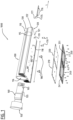
- FIGS 1-4 illustrate a first exemplary embodiment of a luminaire head.
- the luminaire head comprises a thermally conductive metal body 100, a first and second support substrate 210, 220 with a plurality of light emitting elements 230 and electronic circuits 235, a first and a second lens plate 240, 250, and a cap 150 with a connector plate 155.
- the thermally conductive metal body 100 comprises a plate like portion 120, a tube portion 110 and at least one cooling fin 130.
- the plate like portion 120 extends in a longitudinal direction L of the metal body 100 and has a flat first surface 121 and a second surface 122 opposite said first surface.
- the tube portion 110 extends in the longitudinal direction L at said second surface 122.
- a plurality of cooling fins 130 extend away from the second surface 122 adjacent to the tube portion 110, here at both sides of the tube portion 110.
- the flat first surface 121 extends over a length 1 in the longitudinal direction L of the metal body 100, and the tube portion 110 extends over substantially the same length 1 seen in the longitudinal direction L.
- the metal body 100 is an extruded body extruded in one piece in the longitudinal direction L.
- the metal body 100 is made from aluminium.
- the metal body 100 may be anodized to improve the corrosion resistance.
- the first surface 121 functions as a mounting surface for the first and second support substrate 210, 220.
- the first and second support substrate 210, 220 are arranged against the first surface 121, at least in an area opposite the tube portion 110, see figure 2 .
- the first and second support substrate 210, 220 each extend over a width perpendicular to the longitudinal direction L which is at least 80%, more preferably at least 90% of the width w of the plate like portion 120, and even more preferably over substantially the entire width w of the second surface 121 of the plate like portion 120, see figure 4 .
- the first and second support substrate 210, 220 may be arranged next to each other, seen in the longitudinal direction L.
- the tube portion 110 extends substantially in the middle of the second surface 122 of the plate like portion 120.
- the first surface 121 functions as a mounting surface for the substrates 210, 200 with the light emitting elements 230, whilst the tube portion 120 is provided at the opposite second surface 122 of the plate like portion 120.
- the tube portion 120 may be directly connected to the second surface 122, as illustrated, or may be connected through a flange part (not illustrated) with the plate like portion 120. In that manner not only the plurality of cooling fins 130 transport heat away from the plate like portion 120, but also the tube portion 110 itself can conduct heat away from the plate like portion 120.
- the luminaire head when mounted to a support, is oriented substantially parallel respective to the surface to be illuminated.
- the first surface 121 may face downwardly towards the surface to be illuminated, and the plurality of cooling fins 130 may extend upwardly, away from the second surface 122.
- the width w of the plate like portion 120 is at least 50% larger than a maximum width d of the tube portion 110, preferably at least twice the width d of the tube portion 110, see figure 2 .
- the tube portion 110 is a cylindrical portion, and the maximum width d corresponds with the diameter thereof.
- the inner surface 111 of the tube portion 110 may have substantially any one of the following shapes: circular (as in figures 1-4 , 6 and 8 ), a polygon or closed shape having at least three vertices touching a virtual inner circle (as in figure 5 ), a closed shape having at least three curved or straight segments contacting a virtual inner circle (as in figure 7 ).
- the maximum width d may be e.g. between 50 and 100 mm.
- the width w may be e.g. between 75 mm and 500 mm, more preferably between 90 mm and 300 mm.
- the length 1 may be e.g. between 75 mm and 1000 mm, preferably between 75 mm and 600 mm.
- the plurality of cooling fins 130 extends in the longitudinal direction L, allowing the cooling fins 130 to be extruded integrally with the other parts of the metal body 100.
- the plurality of cooling fins 130 comprises at least three first cooling fins 130 arranged on a first side of the tube portion 110 and at least three second cooling fins 130 arranged on a second side of the tube portion 110 opposite the first side.
- eleven cooling fins 130 are provided on either side of the tube portion 110.
- the plurality of cooling fins extends perpendicular on the second surface 122.
- the plurality of cooling fins 130 extends under an angle with respect to the second surface, said angle being between 45° and 90°.
- the tube portion 110 is shaped to receive in a first open end 115 thereof a rigid cylindrical end portion 510 of a mounting base 500, such as a pole for the luminaire head, see figure 3 .
- the tube portion 110 is provided with at least one hole 118, 119 for receiving a fixation means 170, 175 to fix the tube portion 110 to the cylindrical end portion 510 of the mounting base 500.
- the fixation means 170, 175 comprises a fixation clamp 175 with two bore holes for receiving two matching screws 170, e.g. grub screws, see figure 1 and figure 2 .
- the fixation clamp is arranged inside the tube portion 110 and receives end portions of the screws 170 which extend through holes 118, 119.
- the holes 118, 119 are arranged in a portion of the metal body where the tube portion 110 joins the plate like portion.
- the fixation clamp 175 is provided with an upwardly extending part 177 forming a stop for an end portion of the mounting base.
- fixation clamp 175 also other fixation means may be provided for receiving the one or more screws, e.g. one or more nuts.
- the tube portion 110 has a second open end 116 which is closed by a removable closure 150, here in the form of a cap.
- the removable closure 150 is provided with an attaching means, here a connector plate 155 extending inwardly in the tube portion 110.
- the connector plate 155 is provided with one or more connectors 160 and with a cable retainer 165. More generally any components useful for connecting the plurality of light emitting elements 230 or any other device located on the plate like portion (e.g. a sensor, a communication module) may be provided on the connector plate 155. In that way those components are easily accessible since the removable closure 150 with connector plate 155 can be removed from the tube portion 110.
- the removable closure may comprise any attaching means configured for attaching at least one electrical or mechanical or optical component, e.g. the connector 160, a sensor, an electrical circuit such as a driving means, etc., such that the at least one electrical or mechanical or optical component is arranged within the tube portion 110.
- at least one electrical or mechanical or optical component e.g. the connector 160, a sensor, an electrical circuit such as a driving means, etc.
- the connector 160 may be used to connect one or more electrical components of the luminaire head.
- the connector 160 may be used to connect an electrical cable, e.g. an electrical cable connected to the mains and passing from the pole into the tube portion 110, to one or more electrical connection lines connected to the support substrate, typically PCB's, 210, 220 which are arranged on the first surface 121 of the plate like portion 120.
- Those one or more electrical lines may be connected via one or more through-holes 181, 182 extending from the first surface 121 of the plate-like portion 120 into the tube portion 110.
- a wire or cable guide 180 may be provided in each through-hole for guiding the electrical lines in a sealed manner through the through-holes 181, 182.
- the connector 160 may be used to connect a terminal of a first component arranged in the tube portion 110, e.g. a controller to a terminal of another component arranged in the tube portion 110, e.g. a driver.
- the driver may have input terminals connected to an electrical cable coming from the mains, on the one hand, and output terminals connected to one or more electrical components of the luminaire head, on the other hand.
- the driver may be connected to a PCB 210, 220 which is arranged on the first surface 121 of the plate like portion 120, in order to provide power to components arranged on the PCB 210, 220, such as the light emitting elements or a sensor or more generally any other component which needs to be powered.
- one or more through-holes 181, 182 may be provided in the metal body between the first surface 121 of the plate-like portion 120 and the inner part of the tube portion 110.
- the at least one electrical or mechanical or optical component attached to the removable closure 150 may be easily accessed by removing the removable closure 150.
- the need for additional mounting structures within the inner part of the tube portion 110 is reduced, which improves the ease of fabrication of the luminaire head.
- the at least one electrical or mechanical or optical component may be adapted to be attached to the removable closure 150 only via the attaching means 155, replacing or changing the one or more electrical or mechanical or optical component can be done easily without the need to modify the rest of the luminaire head.
- the attaching means 155 may be a slot receiving a support substrate, e.g. a PCB, mounted therein.
- the removable closure 150 is a cap in the exemplary embodiment of Fig. 1 which may be configured for closing off substantially fully the second open end, preferably in a sealed manner.
- the cap 150 may protect the elements arranged within the inner part of the tube portion 110 from undesired foreign elements, e.g. debris, moisture.
- the surface of the cap 150 facing the inner part of the tube portion 110 may be configured for being attached to the one or more electrical or mechanical or optical components and for supporting and holding the one or more electrical or mechanical or optical component within the inner part of the tube portion 110.
- the first and second support substrate 210, 220 may be printed circuit boards.
- the printed circuit boards are so-called AC PCBs comprising circuitry that is able to convert an AC current or line voltage into a DC current, allowing therefore to eliminate the use of a driver.
- each lens plate 240, 250 may be provided with a plurality of lens elements 245, 255 corresponding with the plurality of light elements 230.
- the plurality of light emitting elements 230 of each support substrate 210, 220 comprises at least six light emitting elements 230, more preferably at least eight light emitting elements 230.
- each support substrate 210, 220 is provided with twenty-eight light emitting elements 230 and a corresponding number of lens elements 245, 255.
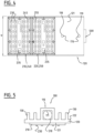
- Figure 5 illustrates another exemplary embodiment of a luminaire head.
- the tube portion 110 has a square cross section with a square inner surface 111 adapted for receiving a cylindrical end portion 510.
- the other illustrated components are similar to the ones described above and therefore a detailed description thereof is omitted.
- Figure 6 illustrates another exemplary embodiment of a luminaire head.
- the tube portion 110 has a cross section with a square outer surface and a round inner surface 111 adapted for receiving a cylindrical end portion 510.
- the cooling fins 130 are slightly inclined with respect to the second surface 122, and not perpendicular on the second surface 122.
- additional cooling fins 131 are provided on the first surface 121 of the plate like portion 120, on either side of the support substrate 210.
- the other illustrated components are similar to the ones described above and therefore a detailed description thereof is omitted.
- Figure 7 illustrates another exemplary embodiment of a luminaire head.
- the tube portion 110 has a cross section with a square outer surface and an inner surface 111 in the form of a closed shape having three vertices touching a virtual inner circle such that the tube portion 110 is adapted for receiving a cylindrical end portion 510.
- the other illustrated components are similar to the ones described above and therefore a detailed description thereof is omitted.
- Figure 8 illustrates yet another exemplary embodiment of a luminaire head.
- the tube portion 110 has a cross section with a square outer surface and an inner surface 111 in the form of circle such that the tube portion 110 is adapted for receiving a cylindrical end portion 510.
- two plate like portions 120, 120' are provided each having a flat first mounting surface 121, 121' and an opposite second surface 122, 122' on which cooling fins 130, 130' are arranged adjacent to the tube portion 110.
- a first support substrate 210 with light emitting elements 230 is arranged against the first surface 121
- a second support substrate 220 with light emitting elements 230 is arranged against the first surface 121'.
- the other illustrated components are similar to the ones described above and therefore a detailed description thereof is omitted.
Landscapes
- Engineering & Computer Science (AREA)
- General Engineering & Computer Science (AREA)
- Non-Portable Lighting Devices Or Systems Thereof (AREA)
- Arrangement Of Elements, Cooling, Sealing, Or The Like Of Lighting Devices (AREA)
Claims (11)
- Leuchtenkopf, umfassend:einen wärmeleitenden Metallkörper (100), umfassend einen plattenartigen Abschnitt (120), einen Rohrabschnitt (110) und mindestens eine Kühlrippe (130);wobei sich der plattenartige Abschnitt (120) in einer Längsrichtung (L) des Metallkörpers erstreckt und eine flache erste Oberfläche (121) und eine zweite Oberfläche (122) aufweist, die der ersten Oberfläche gegenüberliegt, wobei sich der Rohrabschnitt in der Längsrichtung an der zweiten Oberfläche erstreckt und sich vorzugsweise im Wesentlichen in der Mitte der zweiten Oberfläche des plattenartigen Abschnitts erstreckt;wobei sich die mindestens eine Kühlrippe (130) von der zweiten Oberfläche angrenzend an den Rohrabschnitt (110) weg erstreckt;mindestens ein Trägersubstrat (210, 220) mit einer Vielzahl von lichtemittierenden Elementen (230), wobei das mindestens eine Trägersubstrat gegen die erste Oberfläche angeordnet ist, mindestens in einem Bereich gegenüber dem Rohrabschnitt;wobei der Rohrabschnitt ein erstes offenes Ende (116) aufweist, das durch einen entfernbaren Verschluss (150) verschlossen ist, wobei der entfernbare Verschluss (150) eine Kappe ist, die zum im Wesentlichen vollständigen Verschließen des ersten offenen Endes konfiguriert ist;wobei mindestens ein Verbinder (160) an dem entfernbaren Verschluss (150) befestigt ist;wobei der entfernbare Verschluss (150) ein Befestigungsmittel (155) umfasst, das zum Befestigen von mindestens einer elektrischen oder mechanischen oder optischen Komponente derart konfiguriert ist, dass die mindestens eine elektrische oder mechanische oder optische Komponente innerhalb des Rohrabschnitts (110) angeordnet ist;wobei der Rohrabschnitt (110) geformt ist, um in einem zweiten offenen Ende (115) davon einen starren zylindrischen Endabschnitt (510) einer Montagebasis (500), wie eine Stange für den Leuchtenkopf, aufzunehmen;wobei der Rohrabschnitt (110) mit mindestens einem Loch (118, 119) zum Aufnehmen eines Fixiermittels (170) versehen ist, um den Rohrabschnitt an dem zylindrischen Endabschnitt (510) der Montagebasis zu fixieren.
- Leuchtenkopf nach Anspruch 1, wobei sich das mindestens eine Trägersubstrat (210, 220) über eine Breite senkrecht zu der Längsrichtung erstreckt, die mindestens 80 %, vorzugsweise mindestens 90 % der Breite des plattenförmigen Abschnitts beträgt.
- Leuchtenkopf nach Anspruch 1 oder 2, wobei sich die flache erste Oberfläche (121) über eine Länge (1) in der Längsrichtung (L) des Metallkörpers erstreckt und sich der Rohrabschnitt (110) im Wesentlichen über dieselbe Länge (1) in der Längsrichtung erstreckt.
- Leuchtenkopf nach einem der vorstehenden Ansprüche, wobei der Metallkörper (100) ein stranggepresster Körper ist, der in der Längsrichtung in einem Stück stranggepresst ist, vorzugsweise ein stranggepresster Körper, der aus Aluminium stranggepresst ist.
- Leuchtenkopf nach einem der vorstehenden Ansprüche, wobei die Breite des plattenartigen Abschnitts, in einer Breitenrichtung senkrecht zu der Längsrichtung gesehen, mindestens 50 % größer als eine maximale Breite des Rohrabschnitts ist, vorzugsweise mindestens die doppelte Breite des Rohrabschnitts; und, optional, wobei der Rohrabschnitt ein zylindrischer Abschnitt ist und die maximale Breite dem Durchmesser davon entspricht.
- Leuchtenkopf nach einem der vorstehenden Ansprüche, wobei die mindestens eine Kühlrippe (130) mindestens eine erste Kühlrippe, die auf einer ersten Seite des Rohrabschnitts angeordnet ist, und mindestens eine zweite Kühlrippe umfasst, die auf einer zweiten Seite des Rohrabschnitts angeordnet ist, die der ersten Seite gegenüberliegt, vorzugsweise mindestens drei erste Kühlrippen, die auf der ersten Seite des Rohrabschnitts angeordnet sind, und mindestens drei zweite Kühlrippen, die auf der zweiten Seite des Rohrabschnitts angeordnet sind, die der ersten Seite gegenüberliegt.
- Leuchtenkopf nach einem der vorstehenden Ansprüche, wobei die Innenoberfläche (111) des Rohrabschnitts (110), in einem Querschnitt senkrecht zu der Längsrichtung (L) gesehen, im Wesentlichen eine beliebige der folgenden Formen aufweist: kreisförmig, eine geschlossene Form, die mindestens drei Eckpunkte aufweist, die einen virtuellen Innenkreis berühren, eine geschlossene Form, die mindestens drei gekrümmte oder gerade Segmente aufweist, die einen virtuellen Innenkreis berühren.
- Leuchtenkopf nach einem der Ansprüche 1 bis 7, wobei sich die mindestens eine Kühlrippe unter einem Winkel mit Bezug auf die zweite Oberfläche erstreckt, wobei der Winkel zwischen 45° und 90° liegt.
- Leuchtenkopf nach einem der vorstehenden Ansprüche, wobei mindestens eine Linsenplatte über dem mindestens einen Trägersubstrat (210, 220) angeordnet ist.
- Leuchtenkopf nach einem der vorstehenden Ansprüche, wobei die Vielzahl von lichtemittierenden Elementen mindestens sechs lichtemittierende Elemente umfasst; und wobei die mindestens eine Linsenplatte eine Vielzahl von Linsenelementen umfasst, wobei die Vielzahl von Linsenelementen mindestens sechs Linsenelemente umfasst.
- Leuchtenanordnung, umfassend einen Leuchtenkopf (1000) nach einem der vorstehenden Ansprüche und eine Montagebasis (500), die einen starren zylindrischen Endabschnitt (510) aufweist, wobei der zylindrische Endabschnitt (510) in dem zweiten Ende des Rohrabschnitts (110) angeordnet und unter Verwendung eines Fixiermittels (170), das sich durch das Loch in dem Rohrabschnitt erstreckt, an dem Rohrabschnitt fixiert ist.
Applications Claiming Priority (2)
| Application Number | Priority Date | Filing Date | Title |
|---|---|---|---|
| BE2018/5239A BE1026200B1 (fr) | 2018-04-10 | 2018-04-10 | Tête de luminaire compacte |
| PCT/EP2019/059137 WO2019197489A1 (en) | 2018-04-10 | 2019-04-10 | Compact luminaire head |
Publications (2)
| Publication Number | Publication Date |
|---|---|
| EP3775673A1 EP3775673A1 (de) | 2021-02-17 |
| EP3775673B1 true EP3775673B1 (de) | 2024-09-25 |
Family
ID=62597285
Family Applications (1)
| Application Number | Title | Priority Date | Filing Date |
|---|---|---|---|
| EP19715937.9A Active EP3775673B1 (de) | 2018-04-10 | 2019-04-10 | Kompakter leuchtenkopf |
Country Status (8)
| Country | Link |
|---|---|
| US (2) | US11365876B2 (de) |
| EP (1) | EP3775673B1 (de) |
| AU (2) | AU2019250427B2 (de) |
| BE (1) | BE1026200B1 (de) |
| ES (1) | ES2993557T3 (de) |
| PL (1) | PL3775673T3 (de) |
| PT (1) | PT3775673T (de) |
| WO (1) | WO2019197489A1 (de) |
Families Citing this family (6)
| Publication number | Priority date | Publication date | Assignee | Title |
|---|---|---|---|---|
| NL2025081B1 (en) | 2020-03-09 | 2021-10-19 | Schreder Sa | Luminaire head with improved heatsink |
| EP4623246A1 (de) | 2022-11-24 | 2025-10-01 | Schreder S.A. | Leuchtenkopfanordnung |
| NL2033710B1 (en) | 2022-11-24 | 2024-05-30 | Schreder Sa | Luminaire head assembly |
| NL2035989B1 (en) | 2023-10-09 | 2025-04-16 | Schreder Sa | Connector for attaching a luminaire head to a pole and luminaire with the same |
| NL2035991B1 (en) | 2023-10-09 | 2025-04-16 | Schreder Sa | Connector assembly for a luminaire head |
| NL2037361B1 (en) | 2024-03-28 | 2025-10-10 | Schreder Sa | Sleeve coupling member |
Citations (6)
| Publication number | Priority date | Publication date | Assignee | Title |
|---|---|---|---|---|
| US20100226138A1 (en) * | 2009-03-09 | 2010-09-09 | Kuo-Len Lin | Led road lamp holder structure |
| US20120262922A1 (en) * | 2009-08-03 | 2012-10-18 | Jansen Yang | Street lamp with high-power single polycrystalline led chip module |
| US8579469B2 (en) * | 2010-07-07 | 2013-11-12 | Lg Innotek Co., Ltd. | Street lamp |
| US8585244B1 (en) * | 2012-05-31 | 2013-11-19 | Genius Electronic Optical Co., Ltd. | LED lamp |
| US20160003465A1 (en) * | 2014-07-04 | 2016-01-07 | Kmw Inc. | Led Lighting Device |
| US10145554B2 (en) * | 2015-01-27 | 2018-12-04 | Lumenex Solergia Spa | Scaleable solid state lighting apparatus |
Family Cites Families (8)
| Publication number | Priority date | Publication date | Assignee | Title |
|---|---|---|---|---|
| US20100254140A1 (en) * | 2009-04-07 | 2010-10-07 | Fong-Yuan Wen | Lamp holder of led streetlamp with heat-conducting and heat-dissipating capability |
| CN101699139B (zh) * | 2009-10-23 | 2011-12-28 | 厦门靓星光电科技有限公司 | 大功率led路灯 |
| KR101062052B1 (ko) * | 2010-07-02 | 2011-09-02 | 정태호 | 가로등 램프 |
| CN101929642B (zh) * | 2010-08-28 | 2013-04-10 | 广东昭信灯具有限公司 | 一种可替换模块化led路灯 |
| CN102454895A (zh) * | 2010-10-28 | 2012-05-16 | 富准精密工业(深圳)有限公司 | 发光二极管灯具 |
| TWI444127B (zh) * | 2011-10-11 | 2014-07-01 | Delta Electronics Inc | 防水裝置 |
| CN103453343A (zh) * | 2012-05-31 | 2013-12-18 | 全亿大科技(佛山)有限公司 | 发光二极管灯具 |
| US20160053952A1 (en) | 2014-08-25 | 2016-02-25 | GE Lighting Solutions, LLC | Smart luminaire |
-
2018
- 2018-04-10 BE BE2018/5239A patent/BE1026200B1/fr active IP Right Grant
-
2019
- 2019-04-10 EP EP19715937.9A patent/EP3775673B1/de active Active
- 2019-04-10 US US15/733,740 patent/US11365876B2/en active Active
- 2019-04-10 WO PCT/EP2019/059137 patent/WO2019197489A1/en not_active Ceased
- 2019-04-10 ES ES19715937T patent/ES2993557T3/es active Active
- 2019-04-10 PT PT197159379T patent/PT3775673T/pt unknown
- 2019-04-10 AU AU2019250427A patent/AU2019250427B2/en active Active
- 2019-04-10 PL PL19715937.9T patent/PL3775673T3/pl unknown
-
2022
- 2022-06-02 US US17/805,142 patent/US11971161B2/en active Active
-
2023
- 2023-10-02 AU AU2023237215A patent/AU2023237215B2/en active Active
Patent Citations (6)
| Publication number | Priority date | Publication date | Assignee | Title |
|---|---|---|---|---|
| US20100226138A1 (en) * | 2009-03-09 | 2010-09-09 | Kuo-Len Lin | Led road lamp holder structure |
| US20120262922A1 (en) * | 2009-08-03 | 2012-10-18 | Jansen Yang | Street lamp with high-power single polycrystalline led chip module |
| US8579469B2 (en) * | 2010-07-07 | 2013-11-12 | Lg Innotek Co., Ltd. | Street lamp |
| US8585244B1 (en) * | 2012-05-31 | 2013-11-19 | Genius Electronic Optical Co., Ltd. | LED lamp |
| US20160003465A1 (en) * | 2014-07-04 | 2016-01-07 | Kmw Inc. | Led Lighting Device |
| US10145554B2 (en) * | 2015-01-27 | 2018-12-04 | Lumenex Solergia Spa | Scaleable solid state lighting apparatus |
Also Published As
| Publication number | Publication date |
|---|---|
| AU2023237215B2 (en) | 2025-05-08 |
| BE1026200B1 (fr) | 2019-11-12 |
| PL3775673T3 (pl) | 2025-02-03 |
| US11365876B2 (en) | 2022-06-21 |
| US11971161B2 (en) | 2024-04-30 |
| EP3775673A1 (de) | 2021-02-17 |
| AU2023237215A1 (en) | 2023-10-26 |
| AU2019250427B2 (en) | 2023-07-20 |
| PT3775673T (pt) | 2024-11-15 |
| ES2993557T3 (en) | 2025-01-02 |
| US20210148560A1 (en) | 2021-05-20 |
| BE1026200A1 (fr) | 2019-11-05 |
| WO2019197489A1 (en) | 2019-10-17 |
| AU2019250427A1 (en) | 2020-10-29 |
| US20220290852A1 (en) | 2022-09-15 |
Similar Documents
| Publication | Publication Date | Title |
|---|---|---|
| EP3775673B1 (de) | Kompakter leuchtenkopf | |
| US7470055B2 (en) | Mounting structure for LED lighting systems | |
| US7572027B2 (en) | Interconnection arrangement having mortise and tenon connection features | |
| US7159997B2 (en) | Linear lighting apparatus with increased light-transmission efficiency | |
| US20100328945A1 (en) | Led lamp | |
| US9470407B2 (en) | Airfield lighting apparatus | |
| US20040212990A1 (en) | Led task light | |
| US7744258B2 (en) | Outdoor LED lamp assembly | |
| CN108700284B (zh) | 供电模块 | |
| CN106439507A (zh) | 对发光二极管模块的改进或与发光二极管模块相关的改进 | |
| EP2458261B1 (de) | Beleuchtungsmodul und Beleuchtungsvorrichtung damit | |
| US20090040776A1 (en) | Led lamp with a heat dissipation device | |
| CN101592290A (zh) | 发光二极管灯具 | |
| US20100271822A1 (en) | Led lamp | |
| US20130250574A1 (en) | Lighting unit and lighting device | |
| US20100246181A1 (en) | Led lamp | |
| US20080055913A1 (en) | Booster optic | |
| US20120293994A1 (en) | LED Lighting Fixture | |
| CN111947064A (zh) | 灯具 | |
| JP2010135126A (ja) | Led照明装置 | |
| US11473738B1 (en) | Lighting device | |
| US12080833B1 (en) | Lighting system for LED panels | |
| US20090268447A1 (en) | Led lamp | |
| CN205807320U (zh) | 一种底盘及照明装置 | |
| JP5110383B2 (ja) | 電気機器及び照明器具 |
Legal Events
| Date | Code | Title | Description |
|---|---|---|---|
| STAA | Information on the status of an ep patent application or granted ep patent |
Free format text: STATUS: UNKNOWN |
|
| STAA | Information on the status of an ep patent application or granted ep patent |
Free format text: STATUS: THE INTERNATIONAL PUBLICATION HAS BEEN MADE |
|
| PUAI | Public reference made under article 153(3) epc to a published international application that has entered the european phase |
Free format text: ORIGINAL CODE: 0009012 |
|
| STAA | Information on the status of an ep patent application or granted ep patent |
Free format text: STATUS: REQUEST FOR EXAMINATION WAS MADE |
|
| 17P | Request for examination filed |
Effective date: 20201008 |
|
| AK | Designated contracting states |
Kind code of ref document: A1 Designated state(s): AL AT BE BG CH CY CZ DE DK EE ES FI FR GB GR HR HU IE IS IT LI LT LU LV MC MK MT NL NO PL PT RO RS SE SI SK SM TR |
|
| AX | Request for extension of the european patent |
Extension state: BA ME |
|
| DAV | Request for validation of the european patent (deleted) | ||
| DAX | Request for extension of the european patent (deleted) | ||
| STAA | Information on the status of an ep patent application or granted ep patent |
Free format text: STATUS: EXAMINATION IS IN PROGRESS |
|
| 17Q | First examination report despatched |
Effective date: 20210721 |
|
| GRAP | Despatch of communication of intention to grant a patent |
Free format text: ORIGINAL CODE: EPIDOSNIGR1 |
|
| STAA | Information on the status of an ep patent application or granted ep patent |
Free format text: STATUS: GRANT OF PATENT IS INTENDED |
|
| INTG | Intention to grant announced |
Effective date: 20240517 |
|
| RAP3 | Party data changed (applicant data changed or rights of an application transferred) |
Owner name: SCHREDER S.A. |
|
| GRAS | Grant fee paid |
Free format text: ORIGINAL CODE: EPIDOSNIGR3 |
|
| GRAA | (expected) grant |
Free format text: ORIGINAL CODE: 0009210 |
|
| STAA | Information on the status of an ep patent application or granted ep patent |
Free format text: STATUS: THE PATENT HAS BEEN GRANTED |
|
| AK | Designated contracting states |
Kind code of ref document: B1 Designated state(s): AL AT BE BG CH CY CZ DE DK EE ES FI FR GB GR HR HU IE IS IT LI LT LU LV MC MK MT NL NO PL PT RO RS SE SI SK SM TR |
|
| REG | Reference to a national code |
Ref country code: GB Ref legal event code: FG4D |
|
| REG | Reference to a national code |
Ref country code: CH Ref legal event code: EP |
|
| P01 | Opt-out of the competence of the unified patent court (upc) registered |
Free format text: CASE NUMBER: APP_49666/2024 Effective date: 20240902 |
|
| REG | Reference to a national code |
Ref country code: DE Ref legal event code: R096 Ref document number: 602019059396 Country of ref document: DE |
|
| REG | Reference to a national code |
Ref country code: IE Ref legal event code: FG4D |
|
| REG | Reference to a national code |
Ref country code: PT Ref legal event code: SC4A Ref document number: 3775673 Country of ref document: PT Date of ref document: 20241115 Kind code of ref document: T Free format text: AVAILABILITY OF NATIONAL TRANSLATION Effective date: 20241111 |
|
| REG | Reference to a national code |
Ref country code: ES Ref legal event code: FG2A Ref document number: 2993557 Country of ref document: ES Kind code of ref document: T3 Effective date: 20250102 |
|
| REG | Reference to a national code |
Ref country code: LT Ref legal event code: MG9D |
|
| PG25 | Lapsed in a contracting state [announced via postgrant information from national office to epo] |
Ref country code: NO Free format text: LAPSE BECAUSE OF FAILURE TO SUBMIT A TRANSLATION OF THE DESCRIPTION OR TO PAY THE FEE WITHIN THE PRESCRIBED TIME-LIMIT Effective date: 20241225 |
|
| REG | Reference to a national code |
Ref country code: NL Ref legal event code: FP |
|
| PG25 | Lapsed in a contracting state [announced via postgrant information from national office to epo] |
Ref country code: GR Free format text: LAPSE BECAUSE OF FAILURE TO SUBMIT A TRANSLATION OF THE DESCRIPTION OR TO PAY THE FEE WITHIN THE PRESCRIBED TIME-LIMIT Effective date: 20241226 Ref country code: FI Free format text: LAPSE BECAUSE OF FAILURE TO SUBMIT A TRANSLATION OF THE DESCRIPTION OR TO PAY THE FEE WITHIN THE PRESCRIBED TIME-LIMIT Effective date: 20240925 |
|
| PG25 | Lapsed in a contracting state [announced via postgrant information from national office to epo] |
Ref country code: BG Free format text: LAPSE BECAUSE OF FAILURE TO SUBMIT A TRANSLATION OF THE DESCRIPTION OR TO PAY THE FEE WITHIN THE PRESCRIBED TIME-LIMIT Effective date: 20240925 |
|
| PG25 | Lapsed in a contracting state [announced via postgrant information from national office to epo] |
Ref country code: LV Free format text: LAPSE BECAUSE OF FAILURE TO SUBMIT A TRANSLATION OF THE DESCRIPTION OR TO PAY THE FEE WITHIN THE PRESCRIBED TIME-LIMIT Effective date: 20240925 |
|
| PG25 | Lapsed in a contracting state [announced via postgrant information from national office to epo] |
Ref country code: RS Free format text: LAPSE BECAUSE OF FAILURE TO SUBMIT A TRANSLATION OF THE DESCRIPTION OR TO PAY THE FEE WITHIN THE PRESCRIBED TIME-LIMIT Effective date: 20241225 |
|
| PG25 | Lapsed in a contracting state [announced via postgrant information from national office to epo] |
Ref country code: RS Free format text: LAPSE BECAUSE OF FAILURE TO SUBMIT A TRANSLATION OF THE DESCRIPTION OR TO PAY THE FEE WITHIN THE PRESCRIBED TIME-LIMIT Effective date: 20241225 Ref country code: NO Free format text: LAPSE BECAUSE OF FAILURE TO SUBMIT A TRANSLATION OF THE DESCRIPTION OR TO PAY THE FEE WITHIN THE PRESCRIBED TIME-LIMIT Effective date: 20241225 Ref country code: LV Free format text: LAPSE BECAUSE OF FAILURE TO SUBMIT A TRANSLATION OF THE DESCRIPTION OR TO PAY THE FEE WITHIN THE PRESCRIBED TIME-LIMIT Effective date: 20240925 Ref country code: GR Free format text: LAPSE BECAUSE OF FAILURE TO SUBMIT A TRANSLATION OF THE DESCRIPTION OR TO PAY THE FEE WITHIN THE PRESCRIBED TIME-LIMIT Effective date: 20241226 Ref country code: FI Free format text: LAPSE BECAUSE OF FAILURE TO SUBMIT A TRANSLATION OF THE DESCRIPTION OR TO PAY THE FEE WITHIN THE PRESCRIBED TIME-LIMIT Effective date: 20240925 Ref country code: BG Free format text: LAPSE BECAUSE OF FAILURE TO SUBMIT A TRANSLATION OF THE DESCRIPTION OR TO PAY THE FEE WITHIN THE PRESCRIBED TIME-LIMIT Effective date: 20240925 |
|
| REG | Reference to a national code |
Ref country code: AT Ref legal event code: MK05 Ref document number: 1726881 Country of ref document: AT Kind code of ref document: T Effective date: 20240925 |
|
| PG25 | Lapsed in a contracting state [announced via postgrant information from national office to epo] |
Ref country code: IS Free format text: LAPSE BECAUSE OF FAILURE TO SUBMIT A TRANSLATION OF THE DESCRIPTION OR TO PAY THE FEE WITHIN THE PRESCRIBED TIME-LIMIT Effective date: 20250125 |
|
| PG25 | Lapsed in a contracting state [announced via postgrant information from national office to epo] |
Ref country code: RO Free format text: LAPSE BECAUSE OF FAILURE TO SUBMIT A TRANSLATION OF THE DESCRIPTION OR TO PAY THE FEE WITHIN THE PRESCRIBED TIME-LIMIT Effective date: 20240925 Ref country code: SM Free format text: LAPSE BECAUSE OF FAILURE TO SUBMIT A TRANSLATION OF THE DESCRIPTION OR TO PAY THE FEE WITHIN THE PRESCRIBED TIME-LIMIT Effective date: 20240925 |
|
| PG25 | Lapsed in a contracting state [announced via postgrant information from national office to epo] |
Ref country code: EE Free format text: LAPSE BECAUSE OF FAILURE TO SUBMIT A TRANSLATION OF THE DESCRIPTION OR TO PAY THE FEE WITHIN THE PRESCRIBED TIME-LIMIT Effective date: 20240925 Ref country code: AT Free format text: LAPSE BECAUSE OF FAILURE TO SUBMIT A TRANSLATION OF THE DESCRIPTION OR TO PAY THE FEE WITHIN THE PRESCRIBED TIME-LIMIT Effective date: 20240925 |
|
| PG25 | Lapsed in a contracting state [announced via postgrant information from national office to epo] |
Ref country code: CZ Free format text: LAPSE BECAUSE OF FAILURE TO SUBMIT A TRANSLATION OF THE DESCRIPTION OR TO PAY THE FEE WITHIN THE PRESCRIBED TIME-LIMIT Effective date: 20240925 |
|
| PG25 | Lapsed in a contracting state [announced via postgrant information from national office to epo] |
Ref country code: SK Free format text: LAPSE BECAUSE OF FAILURE TO SUBMIT A TRANSLATION OF THE DESCRIPTION OR TO PAY THE FEE WITHIN THE PRESCRIBED TIME-LIMIT Effective date: 20240925 |
|
| REG | Reference to a national code |
Ref country code: DE Ref legal event code: R097 Ref document number: 602019059396 Country of ref document: DE |
|
| PGFP | Annual fee paid to national office [announced via postgrant information from national office to epo] |
Ref country code: DE Payment date: 20250319 Year of fee payment: 7 |
|
| PG25 | Lapsed in a contracting state [announced via postgrant information from national office to epo] |
Ref country code: DK Free format text: LAPSE BECAUSE OF FAILURE TO SUBMIT A TRANSLATION OF THE DESCRIPTION OR TO PAY THE FEE WITHIN THE PRESCRIBED TIME-LIMIT Effective date: 20240925 |
|
| PGFP | Annual fee paid to national office [announced via postgrant information from national office to epo] |
Ref country code: ES Payment date: 20250502 Year of fee payment: 7 |
|
| PLBE | No opposition filed within time limit |
Free format text: ORIGINAL CODE: 0009261 |
|
| STAA | Information on the status of an ep patent application or granted ep patent |
Free format text: STATUS: NO OPPOSITION FILED WITHIN TIME LIMIT |
|
| 26N | No opposition filed |
Effective date: 20250626 |
|
| PG25 | Lapsed in a contracting state [announced via postgrant information from national office to epo] |
Ref country code: SE Free format text: LAPSE BECAUSE OF FAILURE TO SUBMIT A TRANSLATION OF THE DESCRIPTION OR TO PAY THE FEE WITHIN THE PRESCRIBED TIME-LIMIT Effective date: 20240925 |
|
| REG | Reference to a national code |
Ref country code: CH Ref legal event code: H13 Free format text: ST27 STATUS EVENT CODE: U-0-0-H10-H13 (AS PROVIDED BY THE NATIONAL OFFICE) Effective date: 20251125 |
|
| PG25 | Lapsed in a contracting state [announced via postgrant information from national office to epo] |
Ref country code: LU Free format text: LAPSE BECAUSE OF NON-PAYMENT OF DUE FEES Effective date: 20250410 |
|
| PG25 | Lapsed in a contracting state [announced via postgrant information from national office to epo] |
Ref country code: MC Free format text: LAPSE BECAUSE OF FAILURE TO SUBMIT A TRANSLATION OF THE DESCRIPTION OR TO PAY THE FEE WITHIN THE PRESCRIBED TIME-LIMIT Effective date: 20240925 |
|
| PG25 | Lapsed in a contracting state [announced via postgrant information from national office to epo] |
Ref country code: HR Free format text: LAPSE BECAUSE OF FAILURE TO SUBMIT A TRANSLATION OF THE DESCRIPTION OR TO PAY THE FEE WITHIN THE PRESCRIBED TIME-LIMIT Effective date: 20240925 |
|
| PG25 | Lapsed in a contracting state [announced via postgrant information from national office to epo] |
Ref country code: CH Free format text: LAPSE BECAUSE OF NON-PAYMENT OF DUE FEES Effective date: 20250430 |
|
| PGFP | Annual fee paid to national office [announced via postgrant information from national office to epo] |
Ref country code: GB Payment date: 20260319 Year of fee payment: 8 |
|
| PG25 | Lapsed in a contracting state [announced via postgrant information from national office to epo] |
Ref country code: IE Free format text: LAPSE BECAUSE OF NON-PAYMENT OF DUE FEES Effective date: 20250410 |
|
| PGFP | Annual fee paid to national office [announced via postgrant information from national office to epo] |
Ref country code: BE Payment date: 20260319 Year of fee payment: 8 Ref country code: IT Payment date: 20260319 Year of fee payment: 8 |
|
| PGFP | Annual fee paid to national office [announced via postgrant information from national office to epo] |
Ref country code: NL Payment date: 20260319 Year of fee payment: 8 |
|
| PGFP | Annual fee paid to national office [announced via postgrant information from national office to epo] |
Ref country code: FR Payment date: 20260320 Year of fee payment: 8 |
|
| PGFP | Annual fee paid to national office [announced via postgrant information from national office to epo] |
Ref country code: PT Payment date: 20260320 Year of fee payment: 8 |
|
| PGFP | Annual fee paid to national office [announced via postgrant information from national office to epo] |
Ref country code: PL Payment date: 20260323 Year of fee payment: 8 |