EP3775575B1 - Ventileinrichtung - Google Patents
Ventileinrichtung Download PDFInfo
- Publication number
- EP3775575B1 EP3775575B1 EP19721077.6A EP19721077A EP3775575B1 EP 3775575 B1 EP3775575 B1 EP 3775575B1 EP 19721077 A EP19721077 A EP 19721077A EP 3775575 B1 EP3775575 B1 EP 3775575B1
- Authority
- EP
- European Patent Office
- Prior art keywords
- open
- mouth
- communication
- close element
- valve seat
- Prior art date
- Legal status (The legal status is an assumption and is not a legal conclusion. Google has not performed a legal analysis and makes no representation as to the accuracy of the status listed.)
- Active
Links
Images


Classifications
-
- F—MECHANICAL ENGINEERING; LIGHTING; HEATING; WEAPONS; BLASTING
- F15—FLUID-PRESSURE ACTUATORS; HYDRAULICS OR PNEUMATICS IN GENERAL
- F15B—SYSTEMS ACTING BY MEANS OF FLUIDS IN GENERAL; FLUID-PRESSURE ACTUATORS, e.g. SERVOMOTORS; DETAILS OF FLUID-PRESSURE SYSTEMS, NOT OTHERWISE PROVIDED FOR
- F15B13/00—Details of servomotor systems ; Valves for servomotor systems
- F15B13/02—Fluid distribution or supply devices characterised by their adaptation to the control of servomotors
- F15B13/04—Fluid distribution or supply devices characterised by their adaptation to the control of servomotors for use with a single servomotor
-
- F—MECHANICAL ENGINEERING; LIGHTING; HEATING; WEAPONS; BLASTING
- F16—ENGINEERING ELEMENTS AND UNITS; GENERAL MEASURES FOR PRODUCING AND MAINTAINING EFFECTIVE FUNCTIONING OF MACHINES OR INSTALLATIONS; THERMAL INSULATION IN GENERAL
- F16K—VALVES; TAPS; COCKS; ACTUATING-FLOATS; DEVICES FOR VENTING OR AERATING
- F16K11/00—Multiple-way valves, e.g. mixing valves; Pipe fittings incorporating such valves
- F16K11/10—Multiple-way valves, e.g. mixing valves; Pipe fittings incorporating such valves with two or more closure members not moving as a unit
- F16K11/14—Multiple-way valves, e.g. mixing valves; Pipe fittings incorporating such valves with two or more closure members not moving as a unit operated by one actuating member, e.g. a handle
- F16K11/16—Multiple-way valves, e.g. mixing valves; Pipe fittings incorporating such valves with two or more closure members not moving as a unit operated by one actuating member, e.g. a handle which only slides, or only turns, or only swings in one plane
- F16K11/161—Multiple-way valves, e.g. mixing valves; Pipe fittings incorporating such valves with two or more closure members not moving as a unit operated by one actuating member, e.g. a handle which only slides, or only turns, or only swings in one plane only slides
-
- F—MECHANICAL ENGINEERING; LIGHTING; HEATING; WEAPONS; BLASTING
- F16—ENGINEERING ELEMENTS AND UNITS; GENERAL MEASURES FOR PRODUCING AND MAINTAINING EFFECTIVE FUNCTIONING OF MACHINES OR INSTALLATIONS; THERMAL INSULATION IN GENERAL
- F16K—VALVES; TAPS; COCKS; ACTUATING-FLOATS; DEVICES FOR VENTING OR AERATING
- F16K31/00—Actuating devices; Operating means; Releasing devices
- F16K31/44—Mechanical actuating means
- F16K31/52—Mechanical actuating means with crank, eccentric, or cam
- F16K31/524—Mechanical actuating means with crank, eccentric, or cam with a cam
- F16K31/52408—Mechanical actuating means with crank, eccentric, or cam with a cam comprising a lift valve
- F16K31/52416—Mechanical actuating means with crank, eccentric, or cam with a cam comprising a lift valve comprising a multiple-way lift valve
-
- F—MECHANICAL ENGINEERING; LIGHTING; HEATING; WEAPONS; BLASTING
- F15—FLUID-PRESSURE ACTUATORS; HYDRAULICS OR PNEUMATICS IN GENERAL
- F15B—SYSTEMS ACTING BY MEANS OF FLUIDS IN GENERAL; FLUID-PRESSURE ACTUATORS, e.g. SERVOMOTORS; DETAILS OF FLUID-PRESSURE SYSTEMS, NOT OTHERWISE PROVIDED FOR
- F15B11/00—Servomotor systems without provision for follow-up action; Circuits therefor
- F15B11/006—Hydraulic "Wheatstone bridge" circuits, i.e. with four nodes, P-A-T-B, and on-off or proportional valves in each link
-
- F—MECHANICAL ENGINEERING; LIGHTING; HEATING; WEAPONS; BLASTING
- F15—FLUID-PRESSURE ACTUATORS; HYDRAULICS OR PNEUMATICS IN GENERAL
- F15B—SYSTEMS ACTING BY MEANS OF FLUIDS IN GENERAL; FLUID-PRESSURE ACTUATORS, e.g. SERVOMOTORS; DETAILS OF FLUID-PRESSURE SYSTEMS, NOT OTHERWISE PROVIDED FOR
- F15B13/00—Details of servomotor systems ; Valves for servomotor systems
- F15B13/02—Fluid distribution or supply devices characterised by their adaptation to the control of servomotors
- F15B13/04—Fluid distribution or supply devices characterised by their adaptation to the control of servomotors for use with a single servomotor
- F15B13/0401—Valve members; Fluid interconnections therefor
- F15B13/0405—Valve members; Fluid interconnections therefor for seat valves, i.e. poppet valves
-
- F—MECHANICAL ENGINEERING; LIGHTING; HEATING; WEAPONS; BLASTING
- F15—FLUID-PRESSURE ACTUATORS; HYDRAULICS OR PNEUMATICS IN GENERAL
- F15B—SYSTEMS ACTING BY MEANS OF FLUIDS IN GENERAL; FLUID-PRESSURE ACTUATORS, e.g. SERVOMOTORS; DETAILS OF FLUID-PRESSURE SYSTEMS, NOT OTHERWISE PROVIDED FOR
- F15B2211/00—Circuits for servomotor systems
- F15B2211/30—Directional control
- F15B2211/305—Directional control characterised by the type of valves
- F15B2211/3056—Assemblies of multiple valves
- F15B2211/30565—Assemblies of multiple valves having multiple valves for a single output member, e.g. for creating higher valve function by use of multiple valves like two 2/2-valves replacing a 5/3-valve
- F15B2211/30575—Assemblies of multiple valves having multiple valves for a single output member, e.g. for creating higher valve function by use of multiple valves like two 2/2-valves replacing a 5/3-valve in a Wheatstone Bridge arrangement (also half bridges)
Definitions
- the present invention relates to a valve device, in particular a distribution device for control of an operating machine of a hydraulic system.
- valve device described herein has been specifically built for hydraulic systems that use as work fluid non-demineralised sea water.
- valve device described herein has been produced precisely in the perspective of obtaining the performance referred to above.
- valve device described herein is characterised by the features specified in Claim 1.
- the present invention moreover regards a hydraulic system according to Claim 5.
- valve device described herein is a distribution device designed for applications in hydraulic systems that use sea water as work fluid.
- valve device represented is a distributor for controlling a double-acting hydraulic cylinder 100.
- this would be a 4/3 (four-way three-position) distributor.
- the distributor described herein has, instead, a configuration altogether different from a 4/3 distributor of a conventional type.
- the device described herein is characterised in that it envisages a plurality of axial valves for control of the flow between the ports of the valve, the open/close elements of which are governed by cam means in a synchronised way.
- the above configuration makes it possible to obtain a valve device that is provided with a structure and members that are particularly strong from the mechanical standpoint, and that is at the same time able to operate in a precise and reliable way.
- the choice, as type of valve, of an axial valve and the provision of a plurality of axial valves that are structurally independent of one another, associated to the different mouths of the device constitute aspects that are of determining importance to achieve the aforesaid results.
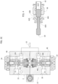
- valve device illustrated designated as a whole by the reference number 10, comprises a block 2 on which an inlet 21, an outlet 22, and the plurality of mouths 23, 24, 25, and 26 are provided.
- the inlet 21 is connected to the delivery branch of the hydraulic circuit, whereas the outlet 22 is connected to the discharge branch.
- the mouths 23 and 24 are both connected to the inlet 21 via ducts 28 provided in the block 2; on the other hand, the mouths 25 and 26 are both connected to the outlet 22 via further ducts 32 provided in the block 2.
- the mouths 23 and 24 constitute two delivery mouths of the device, which, within the hydraulic system illustrated in Figure 5 , are each connected to one of the two chambers 100a and 100b of the cylinder 100.
- the two mouths 25 and 26 both constitute mouths for return of the work fluid to the device 10, which, within the system illustrated in Figure 5 , are also each connected to one of the two chambers 100a and 100b of the cylinder 100.
- the device 10 comprises a first valve 42 and a second valve 44, which are provided for controlling communication, respectively, between the mouth 23 and the inlet 21 and between the mouth 24 and the inlet 21. Moreover, the device 10 comprises a third valve 46 and a fourth valve 48, which are provided for controlling communication, respectively, between the mouth 25 and the outlet 22 and between the mouth 26 and the outlet 22.
- the valves in question are valves of an axial type, i.e., provided with an open/close element mobile in a direction orthogonal to the section of passage defined by the valve seat.
- Figure 4 illustrates in detail one of such valves, according to a preferred embodiment.
- This comprises an axially perforated valve body 60 and an open/close element 62 slidably mounted within the body 60.
- the body 60 identifies an axial port 60A and a series of radial ports 60B.
- the conical valve seat 60C In the space comprised between the axial port 60A and the radial ports 60B, provided on the valve body 60 is the conical valve seat 60C, aligned with the main axis of the valve body 60.
- the open/close element 62 has a corresponding conical portion designed to engage the valve seat 60C, in this condition closing communication between the ports 60A and 60B.
- the open/close element 62 has opposite active surfaces 62A and 62A' on which the work fluid comes to act on the side upstream of the valve and which are sized with respect to one another in such a way that the open/close element 62 is kept by the work fluid in the closed position.
- the ducts 34 that are designed to carry the work fluid to the surfaces 62A' of the open/close elements, which are located in the opposite position with respect to the axial port 60A of the valve body.
- the difference between the surfaces 62A and 62A' is in any case minimal, this in order to facilitate driving of the open/close elements 62, which will be described in what follows.
- valves 42 and 44 like the valves 46 and 48, will operate in an alternating way on the basis of the command that is to be transmitted to the cylinder 100.
- valves 42 and 48, on one side, and the valves 44 and 46, on the other side will have to operate in a synchronised way, to enable driving of the cylinder 100.
- the device 10 comprises a driving member 80 provided with a series of cam surfaces 82, 84, 86, 88, which are designed to co-operate with respective tappet members 42C, 44C, 46C, and 48C arranged so as to engage with the open/close elements of the valves 42, 44, 46, 48.
- the open/close elements 62 are pushed against the tappet members by elastic elements (not illustrated) housed in the cavities provided on the ends of the open/close elements opposite to the respective conical portions designed to engage the valve seats 60C.
- the cam surfaces 82, 84, 86, 88 have a ramp profile.
- the member 80 is driven in a movement of translation, by an actuator assembly 92, between a first position, in which the cam surfaces 82 and 88 drive the open/close elements of the valves 42 and 48 into the open position, via the tappet members of the open/close elements themselves, and a second position, in which the cam surfaces 84 and 86 drive the open/close elements of the valves 44 and 46 into the open position, once again via the tappet members carried by the open/close elements themselves.
- cam surfaces 82, 84, 86, and 88 are set with respect to one another in such a way that, when the portions 82 and 88 or 84 and 86 govern the respective open/close elements, the other two surfaces remain, instead, inactive.
- each tappet member - designated in the figure by the reference 64 - is provided in the same body that defines the open/close element 62 itself.
- a third working position is moreover envisaged, which is intermediate between the two positions referred to above, where all the cam surfaces are inactive and the valves 42, 44, 46, 48 are all kept closed.
- the actuator assembly 92 which is designed to drive the member 80, comprises a stepper motor, connected to which is a screw transmission member.
- the device 10 further comprises a position sensor 96, for example a linear transducer, which is designed to measure the position of a control element 98, which is located outside the block 2 and is connected in a fixed way with respect to the driving member 80 ( Figure 2A ).
- the control unit of the device may be configured for governing the actuator assembly 92 on the basis of the data coming from the position sensor 96 so as to ensure correct positioning of the driving member 80 in the various working positions, for any condition of the device and in a way constant in time.
- This system enables precise control of the position of the member 80, which is able to follow with precise dynamics an analog reference, proportional to the desired position, coming from the control-system controller.
- the control unit may moreover be provided with an enable input (in the absence of which it brings the driving member 80 into a central position, irrespective of the value of the analog input), and two further inputs for selection of the direction of movement.
- the above architecture facilitates control of the device, which may also be operated directly by a proportional joystick or by a remote control, which typically supplies an analog signal and two direction signals.
- the position of the member 80 may be made available on an analog output for the control-system controller or for diagnostic purposes.
- the control unit of the device may also be interfaced with telemonitoring/remote-diagnostics systems.
- the valve device 10 is able to provide a condition of simultaneous closing both of the delivery passageways and of the return passageways, as a result of simultaneous closing of the valves 42 and 44, which are located on the delivery side, and of the valves 46 and 48, which are located on the return side.
- This condition provides safety in regard to possible malfunctioning of the hydraulic system.
- the device described herein is provided for enabling a proportional opening of the passageways, thanks to the ramp cams, which bring about rising of the open/close elements 42B, 44B, 46B, 48B.
- This device is consequently able to carry out a precise and reliable control of the hydraulic machine referred to herein.
Landscapes
- Engineering & Computer Science (AREA)
- General Engineering & Computer Science (AREA)
- Mechanical Engineering (AREA)
- Physics & Mathematics (AREA)
- Fluid Mechanics (AREA)
- Multiple-Way Valves (AREA)
- Mechanically-Actuated Valves (AREA)
- Lift Valve (AREA)
- Fluid-Driven Valves (AREA)
- Polarising Elements (AREA)
- Details Of Valves (AREA)
Claims (7)
- Ventileinrichtung zum Verteilen eines Arbeitsfluids an eine Arbeitsmaschine eines Hydrauliksystems, wobei die Einrichtung umfasst:- einen Ventilblock (2) mit einem Einlass (21) und mindestens einer ersten Mündung (23) und einer zweiten Mündung (24);- einen ersten Ventilsitz (42A), der einen Durchgang definiert, der dazu ausgelegt ist, die erste Mündung (23) in Verbindung mit dem Einlass (21) zu setzen, und ein erstes Öffnungs-/Schließelement (42B), das den ersten Ventilsitz (42A) schließt;- einen zweiten Ventilsitz (44A), der einen Durchgang definiert, der dazu ausgelegt ist, die zweite Mündung (24) in Verbindung mit dem Einlass (21) zu setzen, und ein zweites Öffnungs-/Schließelement (44B), das den zweiten Ventilsitz (44A) schließt; und- ein Antriebsglied (80), das durch einen Aktuator gesteuert wird und zwischen einer ersten Position und einer zweiten Position bewegbar ist, wobei das Antriebsglied eine erste Nockenfläche (82) und eine zweite Nockenfläche (84) aufweist, die dazu ausgelegt sind, mit einem ersten Stößelglied (42C), das mit dem ersten Öffnungs-/Schließelement (42B) verbunden ist, bzw. mit einem zweiten Stößelglied (44C), das mit dem zweiten Öffnungs-/Schließelement (44B) verbunden ist, in Eingriff zu kommen,wobei die erste und die zweite Nockenfläche (82, 84) so vorgesehen sind, dass in der ersten Position des Antriebsglieds (80) das erste Öffnungs-/Schließelement (42B) durch die erste Nockenfläche (82) über das erste Stößelglied (42C) in die geöffnete Position getrieben wird, um die erste Mündung (23) in Verbindung mit dem Einlass (21) zu setzen, und in der zweiten Position das zweite Öffnungs-/Schließelement (44B) durch die zweite Nockenfläche (84) über das zweite Stößelglied (44C) in die geöffnete Position getrieben wird, um die zweite Öffnung (24) in Verbindung mit dem Einlass (21) zu setzen,wobei der Ventilblock (2) aufweist:- einen Auslass (22) und eine dritte Mündung (25) und eine vierte Mündung (26);- einen dritten Ventilsitz (46A), der einen Durchgang definiert, der dazu ausgelegt ist, die dritte Mündung (25) mit dem Auslass (22) in Verbindung zu setzen, und ein drittes Öffnungs-/Schließelement (46B), das den dritten Ventilsitz (46A) schließt; und- einen vierten Ventilsitz (48A), der einen Durchgang definiert, der dazu ausgelegt ist, die vierte Mündung (26) in Verbindung mit dem Auslass (22) zu setzen, und ein viertes Öffnungs-/Schließelement (48B), das den vierten Ventilsitz (48A) schließt,wobei das Antriebsglied (80) eine dritte Nockenfläche (86) und eine vierte Nockenfläche (88) aufweist, die mit einem dritten Stößelglied (46C), das mit dem dritten Öffnungs-/Schließelement (46B) verbunden ist, beziehungsweise mit einem vierten Stößelglied (48C), das mit dem vierten Öffnungs-/Schließelement (48B) verbunden ist, in Eingriff stehen,wobei die dritte und die vierte Nockenfläche (86, 88) so vorgesehen sind, dass in der ersten Position des Antriebsglieds (80) das vierte Öffnungs-/Schließelement (48B) durch die vierte Nockenfläche (88) über das vierte Stößelglied (48C) in die geöffnete Position getrieben wird, um die vierte Mündung (26) mit dem Auslass (22) in Verbindung zu setzen, und in der zweiten Position das dritte Öffnungs-/Schließelement (46B) durch die dritte Nockenfläche (86) über das dritte Stößelglied (46C) in die geöffnete Position getrieben wird, um die dritte Mündung (25) in Verbindung mit dem Auslass (22) zu setzen,wobei das Antriebsglied (80) durch den Aktuator (92) in eine Translationsbewegung zwischen der ersten Position und der zweiten Position versetzt wird,wobei die erste, die zweite, die dritte und die vierte Nockenfläche (82, 84, 86, 88) auf dem Antriebsglied (80) in Bezug zueinander so positioniert sind, dass in der ersten Position des Antriebsglieds (80) das erste und das vierte Öffnungs-/Schließelement (42B, 48B) durch die erste und die vierte Nockenfläche (82, 88) in die geöffnete Position getrieben werden, um gleichzeitig die erste Mündung (23) in Verbindung mit dem Einlass (21) und die vierte Mündung (26) in Verbindung mit dem Auslass (22) zu setzen, und in der zweiten Position des Antriebsglieds (80) das zweite und das dritte Öffnungs-/Schließelement (44B, 46B) durch die zweite und die dritte Nockenfläche (84, 86) in die geöffnete Position getrieben werden, um gleichzeitig die zweite Mündung (24) in Verbindung mit dem Einlass (21) und die dritte Mündung (25) in Verbindung mit dem Auslass (22) zu setzen,dadurch gekennzeichnet, dass für jeden Ventilsitz (60C) und das entsprechende Öffnungs-/Schließelement (62) das Öffnungs-/Schließelement in einer Richtung orthogonal zu dem durch den Ventilsitz definierten Strömungsabschnitt bewegbar ist.
- Vorrichtung nach Anspruch 1, wobei das Antriebsglied (80) in einer dritten Position zwischen der ersten und der zweiten Position positioniert werden kann, in der die Nockenflächen (82, 84, 86, 88) alle inaktiv sind und die Öffnungs-/Schließelemente (42B, 44B, 46B, 48B) alle in einer geschlossenen Position sind.
- Vorrichtung nach Anspruch 1, wobei das Öffnungs-/Schließelement gegenüberliegende Flächen (62A, 62A') aufweist, die dazu ausgelegt sind, dem Druck des Arbeitsfluids auf der stromaufwärtigen Seite des Ventilsitzes ausgesetzt zu sein, wobei diese Flächen in Bezug zueinander so bemessen sind, dass das Öffnungs-/Schließelement aufgrund des auf diese Flächen wirkenden Drucks normalerweise in der geschlossenen Position gehalten wird, wenn keine Einwirkung durch das Antriebsglied erfolgt.
- Vorrichtung nach einem der vorhergehenden Ansprüche, wobei die Nockenflächen (82, 84, 86, 88) ein Rampenprofil aufweisen.
- Hydrauliksystem, umfassend:- eine Einrichtung zum Zuführen eines Arbeitsfluids;- eine Arbeitsmaschine, die für den Betrieb mit dem Arbeitsfluid ausgelegt ist und eine erste Kammer (100A), (100B) oder einen ersten Durchgang und eine zweite Kammer oder einen zweiten Durchgang umfasst, die so ausgelegt sind, dass sie selektiv und abwechselnd miteinander einen Strom des Arbeitsfluids aufnehmen oder zuführen; und- eine Ventileinrichtung nach einem der vorhergehenden Ansprüche,wobei der Einlass (21) der Ventileinrichtung (10) mit der Versorgungseinrichtung verbunden ist, und wobei die erste und die zweite Mündung (23, 24) mit der ersten bzw. zweiten Kammer (100A, 100B) verbunden sind und die dritte und die vierte Mündung (25 und 26) mit der ersten bzw. zweiten Kammer (100A, 100B) verbunden sind.
- Hydrauliksystem nach Anspruch 5, wobei die Versorgungseinrichtung dazu ausgelegt ist, das Wasser aus einem natürlichen Gewässer zu entnehmen, um das Wasser als Arbeitsfluid zu verwenden.
- System nach Anspruch 5 oder Anspruch 6, wobei der Auslass (22) der Einrichtung mit einem Abfluss in Verbindung gesetzt ist, der zum Ablassen des Arbeitsfluids aus dem System vorgesehen ist.
Applications Claiming Priority (2)
| Application Number | Priority Date | Filing Date | Title |
|---|---|---|---|
| IT201800004097A IT201800004097A1 (it) | 2018-03-29 | 2018-03-29 | Dispositivo di valvola |
| PCT/IB2019/052425 WO2019186379A1 (en) | 2018-03-29 | 2019-03-26 | Valve device |
Publications (3)
| Publication Number | Publication Date |
|---|---|
| EP3775575A1 EP3775575A1 (de) | 2021-02-17 |
| EP3775575C0 EP3775575C0 (de) | 2024-08-28 |
| EP3775575B1 true EP3775575B1 (de) | 2024-08-28 |
Family
ID=62597984
Family Applications (1)
| Application Number | Title | Priority Date | Filing Date |
|---|---|---|---|
| EP19721077.6A Active EP3775575B1 (de) | 2018-03-29 | 2019-03-26 | Ventileinrichtung |
Country Status (4)
| Country | Link |
|---|---|
| EP (1) | EP3775575B1 (de) |
| ES (1) | ES2999035T3 (de) |
| IT (1) | IT201800004097A1 (de) |
| WO (1) | WO2019186379A1 (de) |
Family Cites Families (4)
| Publication number | Priority date | Publication date | Assignee | Title |
|---|---|---|---|---|
| US2691990A (en) * | 1952-07-31 | 1954-10-19 | Electrol Inc | Selector valve |
| US2837062A (en) * | 1957-03-28 | 1958-06-03 | Thorpe Joseph | Hydraulic power unit |
| US3411537A (en) * | 1966-12-15 | 1968-11-19 | Honeywell Inc | Fluid diverting valve |
| JP2004247179A (ja) * | 2003-02-14 | 2004-09-02 | Hitachi Ltd | 遮断器の流体圧駆動装置 |
-
2018
- 2018-03-29 IT IT201800004097A patent/IT201800004097A1/it unknown
-
2019
- 2019-03-26 WO PCT/IB2019/052425 patent/WO2019186379A1/en not_active Ceased
- 2019-03-26 EP EP19721077.6A patent/EP3775575B1/de active Active
- 2019-03-26 ES ES19721077T patent/ES2999035T3/es active Active
Also Published As
| Publication number | Publication date |
|---|---|
| WO2019186379A1 (en) | 2019-10-03 |
| EP3775575A1 (de) | 2021-02-17 |
| ES2999035T3 (en) | 2025-02-24 |
| EP3775575C0 (de) | 2024-08-28 |
| IT201800004097A1 (it) | 2019-09-29 |
Similar Documents
| Publication | Publication Date | Title |
|---|---|---|
| US6457487B1 (en) | Hydraulic system with three electrohydraulic valves for controlling fluid flow to a load | |
| EP0017537B1 (de) | Pulsförmig gesteuerter elektrohydraulischer Stellantrieb | |
| US10590962B2 (en) | Directional control valve | |
| US10753375B2 (en) | Actuating unit for a process valve and process valve | |
| US8393348B2 (en) | Directional control valve device and directional control valve device block having directional control valve devices | |
| CA2093863A1 (en) | Pneumatic control front valve | |
| US6357276B1 (en) | System and method for calibrating a independent metering valve | |
| US20200191173A1 (en) | Electropneumatic controller and process control device equipped therewith | |
| JP7795870B2 (ja) | バルブアセンブリ | |
| EP3775575B1 (de) | Ventileinrichtung | |
| US9915355B2 (en) | Valve having open-center spool with separated inserts | |
| EP2891805B1 (de) | Steueranordnung und Steuerventil für eine derartige Steueranordnung | |
| US4515181A (en) | Flow control valve assembly wth quick response | |
| KR20090078785A (ko) | 머저러티 보팅을 이용한 직동 유압이동블록 | |
| EP3374679B1 (de) | Multifunktionelle sanitärventil und verfahren zum betrieb davon | |
| JPH0660697B2 (ja) | 5ポ−ト3位置方向制御弁ユニツト | |
| US4102355A (en) | Diaphragm multi-port valve assembly | |
| US10072765B2 (en) | Valve having spool assembly with insert divider | |
| EP4603712A1 (de) | Flüssigkeitsbetriebener kreislauf zur versorgung von primär- und hilfsversorgungseinrichtungen mit vordefinierten prioritäten | |
| HK40051812A (zh) | 数字比例压力控制器 | |
| US3516438A (en) | Multi-way fluid control valve | |
| RU2241566C2 (ru) | Система компенсации погрешности обеспечения ковочного размера радиально-ковочной машины | |
| RU2056553C1 (ru) | Распределитель | |
| WO2010075867A1 (en) | An axial displacing rotary spool valve and a method of operating an axially displacing rotary spool valve | |
| JPS6039882B2 (ja) | パイロツト制御弁 |
Legal Events
| Date | Code | Title | Description |
|---|---|---|---|
| STAA | Information on the status of an ep patent application or granted ep patent |
Free format text: STATUS: UNKNOWN |
|
| STAA | Information on the status of an ep patent application or granted ep patent |
Free format text: STATUS: THE INTERNATIONAL PUBLICATION HAS BEEN MADE |
|
| PUAI | Public reference made under article 153(3) epc to a published international application that has entered the european phase |
Free format text: ORIGINAL CODE: 0009012 |
|
| STAA | Information on the status of an ep patent application or granted ep patent |
Free format text: STATUS: REQUEST FOR EXAMINATION WAS MADE |
|
| 17P | Request for examination filed |
Effective date: 20200929 |
|
| AK | Designated contracting states |
Kind code of ref document: A1 Designated state(s): AL AT BE BG CH CY CZ DE DK EE ES FI FR GB GR HR HU IE IS IT LI LT LU LV MC MK MT NL NO PL PT RO RS SE SI SK SM TR |
|
| AX | Request for extension of the european patent |
Extension state: BA ME |
|
| DAV | Request for validation of the european patent (deleted) | ||
| DAX | Request for extension of the european patent (deleted) | ||
| STAA | Information on the status of an ep patent application or granted ep patent |
Free format text: STATUS: EXAMINATION IS IN PROGRESS |
|
| 17Q | First examination report despatched |
Effective date: 20230120 |
|
| GRAP | Despatch of communication of intention to grant a patent |
Free format text: ORIGINAL CODE: EPIDOSNIGR1 |
|
| STAA | Information on the status of an ep patent application or granted ep patent |
Free format text: STATUS: GRANT OF PATENT IS INTENDED |
|
| INTG | Intention to grant announced |
Effective date: 20240319 |
|
| GRAS | Grant fee paid |
Free format text: ORIGINAL CODE: EPIDOSNIGR3 |
|
| GRAA | (expected) grant |
Free format text: ORIGINAL CODE: 0009210 |
|
| STAA | Information on the status of an ep patent application or granted ep patent |
Free format text: STATUS: THE PATENT HAS BEEN GRANTED |
|
| AK | Designated contracting states |
Kind code of ref document: B1 Designated state(s): AL AT BE BG CH CY CZ DE DK EE ES FI FR GB GR HR HU IE IS IT LI LT LU LV MC MK MT NL NO PL PT RO RS SE SI SK SM TR |
|
| REG | Reference to a national code |
Ref country code: GB Ref legal event code: FG4D |
|
| REG | Reference to a national code |
Ref country code: CH Ref legal event code: EP |
|
| REG | Reference to a national code |
Ref country code: DE Ref legal event code: R096 Ref document number: 602019057849 Country of ref document: DE |
|
| REG | Reference to a national code |
Ref country code: IE Ref legal event code: FG4D |
|
| U01 | Request for unitary effect filed |
Effective date: 20240926 |
|
| U07 | Unitary effect registered |
Designated state(s): AT BE BG DE DK EE FI FR IT LT LU LV MT NL PT RO SE SI Effective date: 20241018 |
|
| PG25 | Lapsed in a contracting state [announced via postgrant information from national office to epo] |
Ref country code: NO Free format text: LAPSE BECAUSE OF FAILURE TO SUBMIT A TRANSLATION OF THE DESCRIPTION OR TO PAY THE FEE WITHIN THE PRESCRIBED TIME-LIMIT Effective date: 20241128 |
|
| PG25 | Lapsed in a contracting state [announced via postgrant information from national office to epo] |
Ref country code: GR Free format text: LAPSE BECAUSE OF FAILURE TO SUBMIT A TRANSLATION OF THE DESCRIPTION OR TO PAY THE FEE WITHIN THE PRESCRIBED TIME-LIMIT Effective date: 20241129 Ref country code: PL Free format text: LAPSE BECAUSE OF FAILURE TO SUBMIT A TRANSLATION OF THE DESCRIPTION OR TO PAY THE FEE WITHIN THE PRESCRIBED TIME-LIMIT Effective date: 20240828 |
|
| PG25 | Lapsed in a contracting state [announced via postgrant information from national office to epo] |
Ref country code: IS Free format text: LAPSE BECAUSE OF FAILURE TO SUBMIT A TRANSLATION OF THE DESCRIPTION OR TO PAY THE FEE WITHIN THE PRESCRIBED TIME-LIMIT Effective date: 20241228 |
|
| PG25 | Lapsed in a contracting state [announced via postgrant information from national office to epo] |
Ref country code: HR Free format text: LAPSE BECAUSE OF FAILURE TO SUBMIT A TRANSLATION OF THE DESCRIPTION OR TO PAY THE FEE WITHIN THE PRESCRIBED TIME-LIMIT Effective date: 20240828 |
|
| PG25 | Lapsed in a contracting state [announced via postgrant information from national office to epo] |
Ref country code: RS Free format text: LAPSE BECAUSE OF FAILURE TO SUBMIT A TRANSLATION OF THE DESCRIPTION OR TO PAY THE FEE WITHIN THE PRESCRIBED TIME-LIMIT Effective date: 20241128 |
|
| PG25 | Lapsed in a contracting state [announced via postgrant information from national office to epo] |
Ref country code: RS Free format text: LAPSE BECAUSE OF FAILURE TO SUBMIT A TRANSLATION OF THE DESCRIPTION OR TO PAY THE FEE WITHIN THE PRESCRIBED TIME-LIMIT Effective date: 20241128 Ref country code: PL Free format text: LAPSE BECAUSE OF FAILURE TO SUBMIT A TRANSLATION OF THE DESCRIPTION OR TO PAY THE FEE WITHIN THE PRESCRIBED TIME-LIMIT Effective date: 20240828 Ref country code: NO Free format text: LAPSE BECAUSE OF FAILURE TO SUBMIT A TRANSLATION OF THE DESCRIPTION OR TO PAY THE FEE WITHIN THE PRESCRIBED TIME-LIMIT Effective date: 20241128 Ref country code: IS Free format text: LAPSE BECAUSE OF FAILURE TO SUBMIT A TRANSLATION OF THE DESCRIPTION OR TO PAY THE FEE WITHIN THE PRESCRIBED TIME-LIMIT Effective date: 20241228 Ref country code: HR Free format text: LAPSE BECAUSE OF FAILURE TO SUBMIT A TRANSLATION OF THE DESCRIPTION OR TO PAY THE FEE WITHIN THE PRESCRIBED TIME-LIMIT Effective date: 20240828 Ref country code: GR Free format text: LAPSE BECAUSE OF FAILURE TO SUBMIT A TRANSLATION OF THE DESCRIPTION OR TO PAY THE FEE WITHIN THE PRESCRIBED TIME-LIMIT Effective date: 20241129 |
|
| REG | Reference to a national code |
Ref country code: ES Ref legal event code: FG2A Ref document number: 2999035 Country of ref document: ES Kind code of ref document: T3 Effective date: 20250224 |
|
| U20 | Renewal fee for the european patent with unitary effect paid |
Year of fee payment: 7 Effective date: 20250303 |
|
| PG25 | Lapsed in a contracting state [announced via postgrant information from national office to epo] |
Ref country code: SM Free format text: LAPSE BECAUSE OF FAILURE TO SUBMIT A TRANSLATION OF THE DESCRIPTION OR TO PAY THE FEE WITHIN THE PRESCRIBED TIME-LIMIT Effective date: 20240828 |
|
| PG25 | Lapsed in a contracting state [announced via postgrant information from national office to epo] |
Ref country code: CZ Free format text: LAPSE BECAUSE OF FAILURE TO SUBMIT A TRANSLATION OF THE DESCRIPTION OR TO PAY THE FEE WITHIN THE PRESCRIBED TIME-LIMIT Effective date: 20240828 |
|
| PG25 | Lapsed in a contracting state [announced via postgrant information from national office to epo] |
Ref country code: SK Free format text: LAPSE BECAUSE OF FAILURE TO SUBMIT A TRANSLATION OF THE DESCRIPTION OR TO PAY THE FEE WITHIN THE PRESCRIBED TIME-LIMIT Effective date: 20240828 |
|
| PLBE | No opposition filed within time limit |
Free format text: ORIGINAL CODE: 0009261 |
|
| STAA | Information on the status of an ep patent application or granted ep patent |
Free format text: STATUS: NO OPPOSITION FILED WITHIN TIME LIMIT |
|
| PGFP | Annual fee paid to national office [announced via postgrant information from national office to epo] |
Ref country code: ES Payment date: 20250417 Year of fee payment: 7 |
|
| PGFP | Annual fee paid to national office [announced via postgrant information from national office to epo] |
Ref country code: CH Payment date: 20250401 Year of fee payment: 7 |
|
| 26N | No opposition filed |
Effective date: 20250530 |
|
| PG25 | Lapsed in a contracting state [announced via postgrant information from national office to epo] |
Ref country code: MC Free format text: LAPSE BECAUSE OF FAILURE TO SUBMIT A TRANSLATION OF THE DESCRIPTION OR TO PAY THE FEE WITHIN THE PRESCRIBED TIME-LIMIT Effective date: 20240828 |
|
| PG25 | Lapsed in a contracting state [announced via postgrant information from national office to epo] |
Ref country code: IE Free format text: LAPSE BECAUSE OF NON-PAYMENT OF DUE FEES Effective date: 20250326 |
|
| REG | Reference to a national code |
Ref country code: CH Ref legal event code: U11 Free format text: ST27 STATUS EVENT CODE: U-0-0-U10-U11 (AS PROVIDED BY THE NATIONAL OFFICE) Effective date: 20260401 |
|
| U20 | Renewal fee for the european patent with unitary effect paid |
Year of fee payment: 8 Effective date: 20260302 |
|
| PGFP | Annual fee paid to national office [announced via postgrant information from national office to epo] |
Ref country code: GB Payment date: 20260304 Year of fee payment: 8 |