EP3775497B1 - Turbomaschinenschaufel mit einem inneren strömungskanal mit einer vielzahl von optimal angeordneten störelementen - Google Patents
Turbomaschinenschaufel mit einem inneren strömungskanal mit einer vielzahl von optimal angeordneten störelementen Download PDFInfo
- Publication number
- EP3775497B1 EP3775497B1 EP19736416.9A EP19736416A EP3775497B1 EP 3775497 B1 EP3775497 B1 EP 3775497B1 EP 19736416 A EP19736416 A EP 19736416A EP 3775497 B1 EP3775497 B1 EP 3775497B1
- Authority
- EP
- European Patent Office
- Prior art keywords
- fluid
- connection points
- flow
- angle
- vane
- Prior art date
- Legal status (The legal status is an assumption and is not a legal conclusion. Google has not performed a legal analysis and makes no representation as to the accuracy of the status listed.)
- Active
Links
- 239000012530 fluid Substances 0.000 title claims description 79
- 238000004519 manufacturing process Methods 0.000 claims description 48
- 239000000654 additive Substances 0.000 claims description 17
- 230000000996 additive effect Effects 0.000 claims description 17
- 239000000463 material Substances 0.000 claims description 9
- 230000007423 decrease Effects 0.000 claims description 2
- 239000000843 powder Substances 0.000 description 18
- 238000009826 distribution Methods 0.000 description 6
- 239000007787 solid Substances 0.000 description 6
- 239000007789 gas Substances 0.000 description 5
- 229910052751 metal Inorganic materials 0.000 description 5
- 239000002184 metal Substances 0.000 description 5
- 230000009467 reduction Effects 0.000 description 5
- 238000011144 upstream manufacturing Methods 0.000 description 5
- 238000005461 lubrication Methods 0.000 description 4
- 238000005096 rolling process Methods 0.000 description 4
- 230000009471 action Effects 0.000 description 3
- 230000015572 biosynthetic process Effects 0.000 description 3
- 239000003638 chemical reducing agent Substances 0.000 description 3
- 238000002485 combustion reaction Methods 0.000 description 3
- 239000000243 solution Substances 0.000 description 3
- 238000001816 cooling Methods 0.000 description 2
- 230000004927 fusion Effects 0.000 description 2
- 238000002347 injection Methods 0.000 description 2
- 239000007924 injection Substances 0.000 description 2
- 239000000314 lubricant Substances 0.000 description 2
- 230000001050 lubricating effect Effects 0.000 description 2
- 238000003754 machining Methods 0.000 description 2
- 238000010309 melting process Methods 0.000 description 2
- 238000000034 method Methods 0.000 description 2
- 238000011084 recovery Methods 0.000 description 2
- 230000000717 retained effect Effects 0.000 description 2
- 229910000838 Al alloy Inorganic materials 0.000 description 1
- 241000897276 Termes Species 0.000 description 1
- 229910001069 Ti alloy Inorganic materials 0.000 description 1
- 238000009825 accumulation Methods 0.000 description 1
- WYTGDNHDOZPMIW-RCBQFDQVSA-N alstonine Natural products C1=CC2=C3C=CC=CC3=NC2=C2N1C[C@H]1[C@H](C)OC=C(C(=O)OC)[C@H]1C2 WYTGDNHDOZPMIW-RCBQFDQVSA-N 0.000 description 1
- 230000000903 blocking effect Effects 0.000 description 1
- 210000000481 breast Anatomy 0.000 description 1
- 230000008859 change Effects 0.000 description 1
- 239000000470 constituent Substances 0.000 description 1
- 230000007547 defect Effects 0.000 description 1
- 238000010586 diagram Methods 0.000 description 1
- 235000021183 entrée Nutrition 0.000 description 1
- 238000000605 extraction Methods 0.000 description 1
- 230000004907 flux Effects 0.000 description 1
- 239000000446 fuel Substances 0.000 description 1
- 230000036541 health Effects 0.000 description 1
- 230000017525 heat dissipation Effects 0.000 description 1
- 230000009347 mechanical transmission Effects 0.000 description 1
- 238000002844 melting Methods 0.000 description 1
- 230000008018 melting Effects 0.000 description 1
- 230000004048 modification Effects 0.000 description 1
- 238000012986 modification Methods 0.000 description 1
- 230000008569 process Effects 0.000 description 1
- 230000002035 prolonged effect Effects 0.000 description 1
- 238000009877 rendering Methods 0.000 description 1
- 230000000284 resting effect Effects 0.000 description 1
- 230000002441 reversible effect Effects 0.000 description 1
- 238000001228 spectrum Methods 0.000 description 1
- 239000007858 starting material Substances 0.000 description 1
- 230000003746 surface roughness Effects 0.000 description 1
- 210000003462 vein Anatomy 0.000 description 1
Images


Classifications
-
- F—MECHANICAL ENGINEERING; LIGHTING; HEATING; WEAPONS; BLASTING
- F02—COMBUSTION ENGINES; HOT-GAS OR COMBUSTION-PRODUCT ENGINE PLANTS
- F02C—GAS-TURBINE PLANTS; AIR INTAKES FOR JET-PROPULSION PLANTS; CONTROLLING FUEL SUPPLY IN AIR-BREATHING JET-PROPULSION PLANTS
- F02C7/00—Features, components parts, details or accessories, not provided for in, or of interest apart form groups F02C1/00 - F02C6/00; Air intakes for jet-propulsion plants
- F02C7/12—Cooling of plants
- F02C7/14—Cooling of plants of fluids in the plant, e.g. lubricant or fuel
-
- F—MECHANICAL ENGINEERING; LIGHTING; HEATING; WEAPONS; BLASTING
- F01—MACHINES OR ENGINES IN GENERAL; ENGINE PLANTS IN GENERAL; STEAM ENGINES
- F01D—NON-POSITIVE DISPLACEMENT MACHINES OR ENGINES, e.g. STEAM TURBINES
- F01D9/00—Stators
- F01D9/06—Fluid supply conduits to nozzles or the like
- F01D9/065—Fluid supply or removal conduits traversing the working fluid flow, e.g. for lubrication-, cooling-, or sealing fluids
-
- B—PERFORMING OPERATIONS; TRANSPORTING
- B33—ADDITIVE MANUFACTURING TECHNOLOGY
- B33Y—ADDITIVE MANUFACTURING, i.e. MANUFACTURING OF THREE-DIMENSIONAL [3-D] OBJECTS BY ADDITIVE DEPOSITION, ADDITIVE AGGLOMERATION OR ADDITIVE LAYERING, e.g. BY 3-D PRINTING, STEREOLITHOGRAPHY OR SELECTIVE LASER SINTERING
- B33Y80/00—Products made by additive manufacturing
-
- F—MECHANICAL ENGINEERING; LIGHTING; HEATING; WEAPONS; BLASTING
- F05—INDEXING SCHEMES RELATING TO ENGINES OR PUMPS IN VARIOUS SUBCLASSES OF CLASSES F01-F04
- F05D—INDEXING SCHEME FOR ASPECTS RELATING TO NON-POSITIVE-DISPLACEMENT MACHINES OR ENGINES, GAS-TURBINES OR JET-PROPULSION PLANTS
- F05D2220/00—Application
- F05D2220/30—Application in turbines
- F05D2220/36—Application in turbines specially adapted for the fan of turbofan engines
-
- F—MECHANICAL ENGINEERING; LIGHTING; HEATING; WEAPONS; BLASTING
- F05—INDEXING SCHEMES RELATING TO ENGINES OR PUMPS IN VARIOUS SUBCLASSES OF CLASSES F01-F04
- F05D—INDEXING SCHEME FOR ASPECTS RELATING TO NON-POSITIVE-DISPLACEMENT MACHINES OR ENGINES, GAS-TURBINES OR JET-PROPULSION PLANTS
- F05D2230/00—Manufacture
- F05D2230/30—Manufacture with deposition of material
- F05D2230/31—Layer deposition
-
- F—MECHANICAL ENGINEERING; LIGHTING; HEATING; WEAPONS; BLASTING
- F05—INDEXING SCHEMES RELATING TO ENGINES OR PUMPS IN VARIOUS SUBCLASSES OF CLASSES F01-F04
- F05D—INDEXING SCHEME FOR ASPECTS RELATING TO NON-POSITIVE-DISPLACEMENT MACHINES OR ENGINES, GAS-TURBINES OR JET-PROPULSION PLANTS
- F05D2230/00—Manufacture
- F05D2230/50—Building or constructing in particular ways
- F05D2230/53—Building or constructing in particular ways by integrally manufacturing a component, e.g. by milling from a billet or one piece construction
-
- F—MECHANICAL ENGINEERING; LIGHTING; HEATING; WEAPONS; BLASTING
- F05—INDEXING SCHEMES RELATING TO ENGINES OR PUMPS IN VARIOUS SUBCLASSES OF CLASSES F01-F04
- F05D—INDEXING SCHEME FOR ASPECTS RELATING TO NON-POSITIVE-DISPLACEMENT MACHINES OR ENGINES, GAS-TURBINES OR JET-PROPULSION PLANTS
- F05D2240/00—Components
- F05D2240/10—Stators
- F05D2240/12—Fluid guiding means, e.g. vanes
-
- F—MECHANICAL ENGINEERING; LIGHTING; HEATING; WEAPONS; BLASTING
- F05—INDEXING SCHEMES RELATING TO ENGINES OR PUMPS IN VARIOUS SUBCLASSES OF CLASSES F01-F04
- F05D—INDEXING SCHEME FOR ASPECTS RELATING TO NON-POSITIVE-DISPLACEMENT MACHINES OR ENGINES, GAS-TURBINES OR JET-PROPULSION PLANTS
- F05D2260/00—Function
- F05D2260/20—Heat transfer, e.g. cooling
- F05D2260/213—Heat transfer, e.g. cooling by the provision of a heat exchanger within the cooling circuit
-
- F—MECHANICAL ENGINEERING; LIGHTING; HEATING; WEAPONS; BLASTING
- F05—INDEXING SCHEMES RELATING TO ENGINES OR PUMPS IN VARIOUS SUBCLASSES OF CLASSES F01-F04
- F05D—INDEXING SCHEME FOR ASPECTS RELATING TO NON-POSITIVE-DISPLACEMENT MACHINES OR ENGINES, GAS-TURBINES OR JET-PROPULSION PLANTS
- F05D2260/00—Function
- F05D2260/20—Heat transfer, e.g. cooling
- F05D2260/221—Improvement of heat transfer
- F05D2260/2214—Improvement of heat transfer by increasing the heat transfer surface
- F05D2260/22141—Improvement of heat transfer by increasing the heat transfer surface using fins or ribs
-
- Y—GENERAL TAGGING OF NEW TECHNOLOGICAL DEVELOPMENTS; GENERAL TAGGING OF CROSS-SECTIONAL TECHNOLOGIES SPANNING OVER SEVERAL SECTIONS OF THE IPC; TECHNICAL SUBJECTS COVERED BY FORMER USPC CROSS-REFERENCE ART COLLECTIONS [XRACs] AND DIGESTS
- Y02—TECHNOLOGIES OR APPLICATIONS FOR MITIGATION OR ADAPTATION AGAINST CLIMATE CHANGE
- Y02T—CLIMATE CHANGE MITIGATION TECHNOLOGIES RELATED TO TRANSPORTATION
- Y02T50/00—Aeronautics or air transport
- Y02T50/60—Efficient propulsion technologies, e.g. for aircraft
Definitions
- the present invention relates to the design of an aircraft turbine engine blade arranged in all or part of an air flow and forming a heat exchange surface between said air flow and a fluid which circulates within it. .
- the hydraulic fluid intended to be cooled by the outlet guide vanes can come from different zones of the turbomachine. It may indeed be a fluid circulating through the lubrication chambers of the rolling bearings supporting the motor shafts and/or the fan hub, or even a fluid dedicated to the lubrication of the mechanical transmission elements of the accessory box (AGB “Accessory Geared Box”). Finally, it can also be used to lubricate a fan drive reduction gear, when such a reduction gear is provided on the turbomachine in order to reduce the speed of rotation of its fan.
- the aim of the invention is to propose a blade comprising an internal fluid passage equipped with fins, called disturbing elements, the geometric configuration of which makes it possible to increase the efficiency of exchange to meet increasing performance requirements, while increasing blade strength.
- the subject of the invention is an aircraft turbine engine blade comprising an aerodynamic part extending along a span axis and manufactured in one piece by additive manufacturing, said aerodynamic part comprising an intrados wall and an extrados wall respectively comprising an inner face of the intrados and an inner face of the extrados, these inner faces of the intrados and of the extrados being facing each other and jointly delimiting an internal fluid passage comprising at least one channel defining a general direction of fluid propagation within it, this channel being traversed by a plurality of flow disturbing elements connecting the intrados and extrados walls by presenting each a first connection point on the inner face of intrados, and a second connection point on the inner face of extrados.
- the disturbing elements extend relative to the general direction of fluid propagation by forming a variable angle from one disturbing element to another, and the disturbing elements are irregularly spaced from each other so that the first connection points are arranged in a disordered manner on the inner face of the intrados, and/or the second connection points are arranged in a disordered manner on the inner face of the extrados.
- this blade advantageously has improved compatibility with the additive manufacturing process on a powder bed by limiting the impact of the manufacturing direction, which can lead to imperfections on the aerodynamic walls due to an ordered nature of the disturbing elements. of the prior art.
- the invention also relates to a blade thus defined, the internal fluid passage comprising a first and a second channel each defining a direction of propagation of fluid substantially parallel to the span axis, these first and second channels being traversed by the elements disturbers whose first and second connection points do not follow a particular alignment along the direction of fluid propagation.
- the invention also relates to a blade thus defined, such that for any connection point whatsoever among the first connection points (66a) and/or the second connection points arranged in a disordered manner, this connection point has around it a number N of connection points forming a closed line, internally delimiting a space in which the single connection point is located, the distance between the latter and each of said N points is different for at least three of them, and preferably for each of them.
- the invention also relates to a blade thus defined in which the disturbing elements are spaced apart two by two at the point closest to a distance allowing the flow of the fluid, this distance preferably being between 2 and 10 mm.
- the invention also relates to a blade thus defined, in which the value of the angle formed between each disturbing element and the direction of fluid propagation is between 70 and 110°.
- the invention also relates to a blade thus defined, in which the disturbing elements extend by forming an angle greater than a predefined angle A with respect to a plane parallel to the successive manufacturing layers constituting the aerodynamic part of the blade below which these disturbing elements should be supported during manufacture, the angle A preferably being greater than 30°.
- the invention also relates to a blade thus defined, in which the disturbing elements extend by forming an angle of less than 70° with respect to a plane parallel to the successive layers constituting the blade.
- the invention also relates to a blade thus defined, in which the disturbing elements are bars with a cylindrical section with a diameter of the order of 1 mm.
- the invention also relates to an aircraft engine comprising at least one blade thus defined.
- the turbojet engine 1 conventionally comprises a gas generator 2 comprising a combustion chamber 8 on either side of which are arranged a low pressure compressor 4 and a low pressure turbine 12, this gas generator 2 comprising a high pressure compressor 6, and a high-pressure turbine 10.
- a gas generator 2 comprising a combustion chamber 8 on either side of which are arranged a low pressure compressor 4 and a low pressure turbine 12, this gas generator 2 comprising a high pressure compressor 6, and a high-pressure turbine 10.
- the terms “front” and “rear” are considered in a direction 14 opposite to the main direction of gas flow within the turbojet, this direction 14 being parallel to the axis AX thereof.
- the terms “upstream” AM and “downstream” AV are considered according to the main direction of flow of the gases within the turbojet engine.
- the low pressure compressor 4 and the low pressure turbine 12 form a low pressure body, and are connected to each other by a low pressure shaft 11 centered on the axis AX.
- the high pressure compressor 6 and the high pressure turbine 10 form a high pressure body, and are connected to each other by a high pressure shaft 13 centered on the axis AX and arranged around the low shaft pressure 11.
- Trees are supported by roller bearings 19, which are lubricated by being arranged in enclosures bathed in hydraulic fluid. The same is true for the fan hub 17, also supported by roller bearings 19.
- the turbojet engine 1 also comprises, at the front of the gas generator 2 and of the low-pressure compressor 4, a single fan 15 which is here arranged directly behind an air inlet cone of the engine.
- the fan 15 is rotatable along the axis AX, and surrounded by a fan casing 9. On the figure 1 , it is not driven directly by the low pressure shaft 11, but only driven indirectly by this shaft via a reduction gear 20, which allows it to rotate with a slower speed. Nevertheless, a solution with direct drive of the fan 15, by the low pressure shaft 11, falls within the scope of the invention. It should be noted that direct drive of the fan can be retained without departing from the scope of the invention.
- the turbojet engine 1 defines a primary stream 16 intended to be traversed by a primary flow, as well as a secondary stream 18 intended to be traversed by a secondary flow located radially outwards with respect to the primary flow, the flow of the blower being therefore divided.
- the secondary stream 18 is delimited radially outwards, with respect to the axis of rotation of the turbomachine, in part by an outer shroud 23, preferably metallic, extending rearwards the fan housing 9.
- the turbojet engine 1 is equipped with a set of equipment, for example of the fuel pump type, hydraulic pump, alternator, starter, variable-pitch stator actuator (VSV), valve actuator discharge, or electric power generator.
- a set of equipment for example of the fuel pump type, hydraulic pump, alternator, starter, variable-pitch stator actuator (VSV), valve actuator discharge, or electric power generator.
- VSV variable-pitch stator actuator
- This piece of equipment for the lubrication of the reducer 20.
- This piece of equipment is driven by an accessory box or AGB (not shown), which is also lubricated.
- stator vanes 31 Downstream of the fan 15, in the secondary stream 18, there is provided a ring of guide vanes which are here outlet guide vanes 31 (or OGV, standing for “Outlet Guide Vane”).
- These stator vanes 31 connect the outer shroud 23 to a casing 26 surrounding the low pressure compressor 4. They are circumferentially spaced from each other, and make it possible to straighten the secondary flow after it has passed through the fan 15.
- these blades 31 can also fulfill a structural function, as is the case in the examples of embodiment which are described herein. They ensure the transfer of the forces coming from the reducer and the rolling bearings 19 of the engine shafts and the fan hub, towards the outer shroud 23. Then, these forces can pass through an engine attachment 30 fixed on the shroud 23 and connecting the turbojet to an attachment pylon (not shown) of the aircraft.
- outlet guide vanes 31 provide, in the embodiments which are described herein, a third heat exchanger function between the secondary air flow passing through the crown of vanes, and the hydraulic fluid circulating inside of these blades 31.
- the hydraulic fluid intended to be cooled by the outlet guide vanes 31 is that used to lubricate the rolling bearings 19, and/or the equipment of the turbojet engine, and/or the accessory box, and/ or the reducer 20.
- These vanes 31 thus form part of the fluidic circuit(s) in which the hydraulic fluid is circulated to successively lubricate the associated element(s), then to be cooled.
- outlet guide vanes 31 will be described, but it is noted that the invention as it will be described can be applied to all the vanes 31 of the stator crown centered on the axis AX, or well only at some of these dawns.
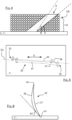
- the guide vane 31 which appears on the figure 2 is a metal part including in particular an aerodynamic part 32, also called a blade, intended to be exposed to the secondary flow identified by F.
- This aerodynamic part 32 is extended on either side by a foot 33 and a head 34 which ensure the attachment of the blade 31 to the casing 26 and to the outer shroud 23.
- the blade 31 further comprises at its root and its head, platforms 36 serving to reconstitute a portion of the secondary vein once this blade is installed on the turbomachine.
- the blade 31 Designed according to the direction of arrival of the secondary flow F to straighten it, the blade 31 extends according to a cambered profile from the foot 33 to the head 34 twisting around an axis called span EV .
- This span axis EV can be perpendicular to an axis AX or inclined as represented on the figure 2 .
- This aerodynamic part 32 comprises an intrados wall 37 and an extrados wall 38 which are spaced from each other on either side of a center line of the profile of the blade, also called the spotted skeleton. by 39 on the picture 3 .
- These intrados 37 and extrados 38 walls are joined at a first end of the skeleton 39 by a leading edge 41 and at a second end of the skeleton 39 by a trailing edge 42.
- the skeleton 39 can be split into an upstream half AM and a downstream half AV separated from each other by a midline of the skeleton located halfway between the leading edge and the trailing edge.
- This guide vane 31 is a metal part formed in a single piece by additive manufacturing on a powder bed, being formed from a plurality of successive and parallel layers of material, in a non-limiting manner of aluminum alloy.
- Additive manufacturing on a powder bed refers to the addition of material layer by layer, on a manufacturing platform of a dedicated machine, to form a physical object from a digital model.
- the powder bed laser melting process is used, which consists in melting part of a thin layer of powder spread by a scraper using a laser on each pass.
- the powder used in laser fusion is not self-supporting.
- the unfused powder of lower layers marked by CI that is to say which is not scanned by the laser, is not able to support the fused powder d 'a consecutive upper layer CS below a minimum draft angle A between the part P and the manufacturing plate T.
- the minimum clearance angle A is defined at 30° with respect to the plate T, and an optimal surface rendering angle B of 60° with respect to the plate below which surface roughness is observed. , especially at the edges of the part.
- the invention provides a preferential orientation of the guide vane 31 during its manufacture with respect to the manufacturing plate T.
- orientation in the lying direction
- the blade 31 is manufactured with the axis EV parallel to the plate T starting with the leading edge 41, because it is thicker than the trailing edge 42, with the upper surface forming with the plate T an angle of 60° at the level of this leading edge , as seen on the figure 6 .
- the successive layers of fused powder constituting this blade 31 extend along the axis EV, and the angle formed between the upper surface 38 and the plate T decreases continuously as the layers of powder stack up to form an angle of 0° at the trailing edge.
- the span axis EV is oriented at an angle of approximately 2 or 3° with respect to the direction of sweep of the scraper marked with U on the figure 5 in order to avoid its blocking, or even tearing of the lower layers in the most severe case.
- This guide vane 31 provides a heat exchanger function between the air flow F which travels through its aerodynamic part 32, and a hydraulic fluid which circulates within it.
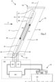
- the aerodynamic part 32 comprises an internal fluid flow passage 43 delimited by the intrados and extrados walls 37 and 38, and more precisely by an interior face of the intrados wall and an interior face of the face extrados which face each other and are in contact with the hydraulic fluid.
- This internal passage 43 comprises a first and a second channel 44 and 46 substantially parallel to the axis EV, offset from each other in a direction orthogonal to the axis EV, and connected together by an angled connection 47.
- the intrados and extrados walls 37 and 38 are connected at the level of a full upstream zone 48 close to the leading edge 41, a full downstream zone 49 close to the trailing edge 42, and at the level of a central solid zone 51.
- the upstream and downstream solid zones 48 and 49 extend from the foot 33 to the head 34, while the central solid zone 51 extends from the foot to the elbow connection 47 while being arranged along the span axis EV between the first and second internal channels to isolate them from each other outside the elbow tap 47.
- the first channel 44 extends from a fluid supply mouth 52, formed at the level of the junction between the aerodynamic part 32 and the foot 33, up to the elbow connection 47 by defining a first direction of propagation of fluid X1 in its breast which is substantially parallel to the span axis EV.
- the second channel 46 extends for its part from the elbow connection 47 to a fluid ejection mouth 53 distinct from the supply mouth 52 and formed in the same way at the level of the interface between the part aerodynamics 32 and the foot 33. This second channel 46 defines a second direction of fluid propagation X2 within it which is substantially parallel to the span axis EV.
- the supply and ejection mouths 52 and 53 are each extended by a recessed volume 54 in the foot 33 forming a fluid connection between the internal passage 43 and a hydraulic circuit of the turbomachine marked by the element 56 on the figure 7 .
- This hydraulic circuit 56 comprises in particular an injection pump 57 and a recovery pump 58, making it possible to apply to the hydraulic fluid the desired direction of circulation along X1 and X2 respectively within the first and second channels 44 and 46.
- hydraulic fluid in the internal passage 43 is carried out at the level of the supply mouth 52 by crossing the associated connection 54, and its extraction is carried out by the ejection mouth 53 after having transited along the first channel and the second channel by passing from one to the other through the elbow connection 47.
- first channel 44 is located on the side of the trailing edge 42, while the second channel 46 is located on the side of the leading edge 41.
- This arrangement is defined to best optimize heat exchange , but it should be noted that the reverse arrangement can be retained without departing from the scope of the invention.
- the idea underlying the invention is to advantageously use the ability to easily produce very complex shapes by additive manufacturing so that the fluid circulating in the internal passage 43 is disturbed in its entirety.
- the guide vane 31 according to the invention thus requires that the disturbing elements be arranged in a disordered manner by forming an indivisible set in repeated patterns along the first and the second channel 44 and 46, to avoid any fluid propagation path which does not would encounter no disturbing element.
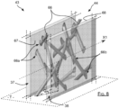
- the first channel 44 comprises a succession of disturbing elements 66 irregularly spaced from each other and extending across it over its entire extent, in other words distributed along the fluidic flow X1. It should be noted that the description of the disturbing elements 66 is carried out for the first channel 44, since the disturbing elements 66 in the second channel 46 follow a similar arrangement and morphology.
- These disturbing elements 66 each comprise a first and a second end 66a and 66b respectively forming a connection point on the inside face of the intrados wall marked with 67, and on the inside face of the extrados wall marked with 68.
- orientation of the disturbing elements is not constant along the channel by extending obliquely with respect to the axis EV.
- the distribution of the connection points 66a and 66b does not follow an alignment or a particular order by forming a cloud of points without any discernible pattern in an overall view of the interior face of the intrados wall 67 or of the extrados 68. More specifically, the connection points 66a and 66b are not all confused with a line, in particular a line parallel to the direction X1.
- This arrangement of disturbing elements 66 in addition to increasing the heat exchange by turbulence, provides improved mechanical strength. Indeed, the variety of different orientations of the disturbing elements 66 allows a better transfer of forces between the intrados and extrados walls 37 and 38, given that for a stress having a direction, there is at least one disturbing element whose orientation comes closest to this direction, and therefore picks up the peak of effort.
- the first connection points 66a are not all included in the same plane parallel to the plate T.
- the ends 66b forming a connection point with the extrados wall 37 are not all manufactured in the same plane parallel to the plate T.
- the first connection points 66a and in the same way the second connection points 66b, are not manufactured simultaneously at the level of the same layer of powder, or more precisely of the same succession of layers of powder, constituting the guide vane 31.
- This aspect makes it possible to overcome an accumulation of residual stresses due to a prolonged action of the laser, which in the opposite case, ie in the case of an ordered arrangement and an alignment along a line of junction disturber-walls of the points connection 66a and / or 66b, would be likely to deform the material at such a line and have repercussions by forming projections on the outer surface of the intrados and extrados walls.
- the arrangement and orientation of the disturbing elements 66 within the guide vane 31 is particularly compatible and well suited to the metal laser melting process, and more broadly to the additive manufacturing process on a powder bed, in that it is permitted to manufacture with the fluidic directions X1 and X2 parallel to the plate T.
- the disturbing elements 66 are generated randomly while respecting various criteria of flow parameterization, exchange performance and manufacturability.
- the disturbing elements 66 must be erected from the inner face of intrados or extrados 67 or 68, depending on the connection point 66a or 66b from which they each begin their manufacture, by forming an angle greater than 30° relative to plate T, or even relative to a plane parallel to the successive layers constituting blade 31 which are formed parallel to plate T.
- the disturbing elements 66 according to the invention must respect an angle with the plate, or in the same way with a plane parallel to the successive layers constituting the blade, of an angle value comprised between 30° and 70° .
- the disruptive elements 66 must also comply with a proximity constraint, taking care not to produce a fluid passage section that is too small, generating poor flow, or on the contrary too large, leading to a loss of efficiency of the exchange. thermal.
- the invention provides for the guide vane 31 that the distance between two disturbing elements measured at the closest points must typically be between 2 and 10 mm.
- the disturbing elements 66 must be oriented with respect to the direction of propagation of this fluid by forming an angle O called orientation of a value comprised between 70° and 110°, and more generally between 60 and 120°. It is understood that even if the direction of propagation of the fluid evolves along the internal passage 43 due to the circumvention of the disturbing elements, reference is here made to the general direction of propagation of the fluid along X1 in the first channel and along X2 in the second channel 46.
- the blade according to the invention comprises an internal fluid flow passage in which disturbing elements 66 are oriented and spaced irregularly from each other according to varied parameters in a chosen and optimized interval, which guarantees an exchange maximum thermal.
- each of the ends of the disturbing elements 66 are connected to the wall so as not to locally form a path free of propagation.
- connection point P3 having around it a number N greater than 3 of connection points, here P1, P2, P4 and P5, formed on the same inner face of the wall and forming a closed line K internally delimiting a space in which said arbitrary connection point P3 is located, the distance D3-1, D3-2, D3-4, D3-5 between the latter and each of said N points is different for at least three of them, and preferably for each of them.
- the guide vane 31 is manufactured "in the recumbent direction" with its span axis EV parallel to the plate T.
- the invention is not limited to this direction of manufacture and could for example provide a so-called “upright” alternative, with the blade 31 manufactured resting on one of its platforms, ie by starting manufacture on the plate from a platform.
- this alternative favors the reduction of supports on the aerodynamic profile to minimize finishing operations.
- this “upright” alternative makes it possible to increase the number of blades 31 that can be manufactured simultaneously on the same plate T.
- the distribution of the disturbing elements 66 according to the invention is not limited in that they follow the span axis EV of the blade, given that the internal passage 43 can present a different morphology to that illustrated on the figure 7 , such as for example serpentine, without departing from the scope of the invention.
- the formation of the disturbing elements 66 according to the invention is applicable whatever the direction of manufacture of the aerodynamic part 32, and more precisely the orientation or orientations of the fluidic passage 43 within the latter, therefore the values of Predefined minimum draft angle A and orientation O are respected.
- this minimum clearance angle A is not necessarily equal to 30°, given that it depends in particular on the nature of the powder used and the machine used.
- the invention could provide for the disturbing elements to form an angle with the plate T of a different value to respect a new angle value A induced by a change of material and/or additive manufacturing process, such as for example using a titanium alloy.
- the distance between two disturbing elements as well as the orientation angle value O can be modified without departing from the scope of the invention, given that these parameters depend on the nature of the fluid circulating in the passage. inside the dawn, and more specifically its viscosity.
- the invention is not limited to solid cylinders, and allows the use of various shapes such as for example with an ovoid, rectangular, triangular, parallelepipedic, conical, prismatic section, or any other shape.
- their diameter can be modified according to the number of disturbing elements 66 desired within the internal passage and the conduction constraints.
- the invention could in particular provide for the diameter to exceed 1 mm, which authorizes them in particular to form an angle with the plate T which exceeds 70°.
- the arrangement of the disturbing elements 66 is particularly effective in increasing the turbulence of the fluid, but it should be noted that the invention could provide for an "asymmetrical" distribution with only the first or the second connection points being disordered while the others being lined up or forming a repeatable pattern as needed. This “asymmetrical” distribution could be favored depending on the specific case, in particular to satisfy another performance condition.
- the invention could provide a turbine blade placed at the outlet of the combustion chamber 8 and whose internal passage this time performs a function of cooling the intrados and extrados walls with a flow of air fresh, taken upstream of the combustion, which travels along this internal passage being disturbed by a set of disturbing elements 66 thus defined.
Landscapes
- Engineering & Computer Science (AREA)
- Chemical & Material Sciences (AREA)
- Mechanical Engineering (AREA)
- General Engineering & Computer Science (AREA)
- Combustion & Propulsion (AREA)
- Physics & Mathematics (AREA)
- Fluid Mechanics (AREA)
- Manufacturing & Machinery (AREA)
- Materials Engineering (AREA)
- Structures Of Non-Positive Displacement Pumps (AREA)
- Turbine Rotor Nozzle Sealing (AREA)
- Powder Metallurgy (AREA)
Claims (11)
- Turbomaschinenschaufel eines Luftfahrzeugs, umfassend einen aerodynamischen Teil (32), der sich entlang einer Spannweitenachse (EV) erstreckt, und in einem Stück durch additive Herstellung hergestellt wird, wobei der aerodynamische Teil eine Druckseitenwand (37) und eine Saugseitenwand (38) umfasst, die jeweils eine Druckseiten-Innenseite (67) und eine Saugseiten-Innenseite (68) umfassen, wobei diese Druckseiten- und Saugseiten-Innenseiten (67, 68) einander gegenüberliegend sind, und gemeinsam einen inneren Fluiddurchlass (43) begrenzen, der mindestens einen Kanal (44; 46) umfasst, der in seinem Inneren eine allgemeine Fluidausbreitungsrichtung (X1; X2) definiert, wobei dieser Kanal von einer Vielzahl von Strömungsstörelementen (66) durchquert wird, die die Druck- und Saugseitenwände (37, 38) durch Aufweisen von jeweils einem ersten Verbindungspunkt (66a) an der Druckseiten-Innenseite (67), und einem zweiten Verbindungspunkt (66b) an der Saugseiten-Innenseite (68) miteinander verbinden,
dadurch gekennzeichnet, dass sich die Störelemente in Bezug auf die allgemeine Fluidausbreitungsrichtung (X1; X2) durch Bilden eines variablen Winkels eines Störelements zu einem anderen erstrecken, und dadurch, dass die Störelemente (66) unregelmäßig voneinander beabstandet sind, sodass die ersten Verbindungspunkte (66a) ungeordnet auf der Druckseiten-Innenseite (67) angeordnet sind, und/oder dadurch, dass die zweiten Verbindungspunkte (66b) ungeordnet auf der Saugseiten-Innenseite (68) angeordnet sind. - Schaufel nach Anspruch 1, dadurch gekennzeichnet, dass der innere Fluiddurchlass (43) einen ersten und einen zweiten Kanal (44, 46) umfasst, die jeweils eine Fluidausbreitungsrichtung (X1, X2) im Wesentlichen parallel zur Spannweitenachse (EV) definieren, wobei dieser erste und zweite Kanal (44, 46) von den Störelementen (66) durchquert werden, deren erster und zweiter Verbindungspunkt (66a, 66b) keiner besonderen Fluchtung entlang der Fluidausbreitungsrichtung (X1, X2) folgen.
- Schaufel nach einem der vorstehenden Ansprüche, dadurch gekennzeichnet, dass für jeden beliebigen Verbindungspunkt (66a, 66b) unter den ersten Verbindungspunkten (66a) und/oder den zweiten Verbindungspunkten, die ungeordnet angeordnet sind, dieser Verbindungspunkt um sich herum eine Anzahl N an Verbindungspunkten aufweist, die eine geschlossene Linie bilden, die innen einen Raum begrenzt, in dem sich der einzige beliebige Verbindungspunkt befindet, wobei der Abstand zwischen diesem letzteren und jedem der N Punkte für mindestens drei unter ihnen, und vorzugsweise für jeden unter ihnen unterschiedlich ist.
- Schaufel nach einem der vorstehenden Ansprüche, dadurch gekennzeichnet, dass- in einer Ansicht von innerhalb des Fluiddurchlasses (43) in einer Richtung lokal im Wesentlichen senkrecht zu, und zur Druckseiten-Innenseite (67) ausgerichtet, alle ersten Verbindungspunkte (66a) derselben jeweils an der Schnittstelle zwischen einer gedachten Primärlinie (L1, L2, L3, L4, L5), die sich parallel zur Fluidausbreitungsrichtung (X1, X2) erstreckt, und einer gedachten Sekundärlinie (F1, F2, F3, F4, F5) senkrecht zur gedachten Primärlinie angeordnet sind, wobei sämtliche der ersten gedachten Linien sich allesamt voneinander unterscheiden und sämtliche der zweiten gedachten Linien sich allesamt voneinander unterscheiden; und/oder- in einer Ansicht von innerhalb des Fluiddurchlasses (43) in einer Richtung lokal im Wesentlichen senkrecht zu, und zur Saugseiten-Innenseite (68) ausgerichtet, alle zweiten Verbindungspunkte (66b) derselben jeweils an der Schnittstelle zwischen einer gedachten Primärlinie, die sich parallel zur Fluidausbreitungsrichtung (X1, X2) erstreckt, und einer gedachten Sekundärlinie senkrecht zur gedachten Primärlinie angeordnet sind, wobei sämtliche der ersten gedachten Linien sich allesamt voneinander unterscheiden und sämtliche der zweiten gedachten Linien sich allesamt voneinander unterscheiden.
- Schaufel nach einem der vorstehenden Ansprüche, wobei die Störelemente paarweise zum nächstgelegenen Punkt um eine Entfernung beabstandet sind, die die freie Strömung des Fluids erlaubt, wobei diese Entfernung vorzugsweise zwischen 2 und 10 mm liegt.
- Schaufel nach einem der vorstehenden Ansprüche, wobei der Wert des zwischen jedem Störelement (66) und der Fluidausbreitungsrichtung (X1, X2) gebildeten Winkels zwischen 70° und 110° liegt.
- Schaufel nach einem der vorstehenden Ansprüche, wobei sich die Störelemente (66) durch Bilden von einem Winkel größer als ein Winkel A erstrecken, der in Bezug auf eine parallele Ebene zu den aufeinanderfolgenden Herstellungsschichten vordefiniert ist, die den aerodynamischen Teil der Schaufel darstellen, wobei diese Störelemente diesseits desselben bei der Herstellung gestützt werden müssten, wobei der Winkel A vorzugsweise größer als 30° ist.
- Schaufel nach einem der vorstehenden Ansprüche, wobei sich die Störelemente (66) durch Bilden von vorzugsweise einem Winkel kleiner als 70° in Bezug auf eine Ebene parallel zu den aufeinanderfolgenden Schichten, die die Schaufel darstellen, erstrecken.
- Schaufel nach einem der vorstehenden Ansprüche, wobei die Störelemente Stäbe mit zylindrischem Querschnitt mit einem Durchmesser in der Größenordnung von 1 mm sind.
- Triebwerk eines Luftfahrzeugs, umfassend mindestens eine Schaufel nach einem der vorstehenden Ansprüche.
- Verfahren zur additiven Herstellung einer Schaufel nach einem der Ansprüche 1 bis 9, durch Stapeln von Werkstoffschichten, die die Schaufel von ihrer Vorderkante an darstellen, auf einer Platte T, bei dem die Spannweitenachse (EV) parallel zur Platte T liegt, und die Saugseitenwand mit der Patte T einen Winkel bildet, der mit Zunahme der gestapelten Schichten kleiner wird.
Applications Claiming Priority (2)
| Application Number | Priority Date | Filing Date | Title |
|---|---|---|---|
| FR1854567A FR3081912B1 (fr) | 2018-05-29 | 2018-05-29 | Aube de turbomachine comprenant un passage interne d'ecoulement de fluide equipe d'une pluralite d'elements perturbateurs a agencement optimise |
| PCT/FR2019/051240 WO2019229362A1 (fr) | 2018-05-29 | 2019-05-28 | Aube de turbomachine comprenant un passage interne d'écoulement de fluide équipé d'une pluralité d'éléments perturbateurs à agencement optimisé |
Publications (2)
| Publication Number | Publication Date |
|---|---|
| EP3775497A1 EP3775497A1 (de) | 2021-02-17 |
| EP3775497B1 true EP3775497B1 (de) | 2023-04-19 |
Family
ID=63490595
Family Applications (1)
| Application Number | Title | Priority Date | Filing Date |
|---|---|---|---|
| EP19736416.9A Active EP3775497B1 (de) | 2018-05-29 | 2019-05-28 | Turbomaschinenschaufel mit einem inneren strömungskanal mit einer vielzahl von optimal angeordneten störelementen |
Country Status (5)
| Country | Link |
|---|---|
| US (1) | US11236673B2 (de) |
| EP (1) | EP3775497B1 (de) |
| CN (1) | CN112105800B (de) |
| FR (1) | FR3081912B1 (de) |
| WO (1) | WO2019229362A1 (de) |
Families Citing this family (3)
| Publication number | Priority date | Publication date | Assignee | Title |
|---|---|---|---|---|
| FR3081912B1 (fr) * | 2018-05-29 | 2020-09-04 | Safran Aircraft Engines | Aube de turbomachine comprenant un passage interne d'ecoulement de fluide equipe d'une pluralite d'elements perturbateurs a agencement optimise |
| US11680530B1 (en) | 2022-04-27 | 2023-06-20 | General Electric Company | Heat exchanger capacity for one or more heat exchangers associated with a power gearbox of a turbofan engine |
| US11834992B2 (en) | 2022-04-27 | 2023-12-05 | General Electric Company | Heat exchanger capacity for one or more heat exchangers associated with an accessory gearbox of a turbofan engine |
Family Cites Families (24)
| Publication number | Priority date | Publication date | Assignee | Title |
|---|---|---|---|---|
| GB2399405A (en) * | 2003-03-10 | 2004-09-15 | Alstom | Enhancement of heat transfer |
| US8616834B2 (en) * | 2010-04-30 | 2013-12-31 | General Electric Company | Gas turbine engine airfoil integrated heat exchanger |
| RU2014125561A (ru) * | 2011-11-25 | 2015-12-27 | Сименс Акциенгезелльшафт | Аэродинамический профиль с охлаждающими каналами |
| FR2989110B1 (fr) | 2012-04-05 | 2016-09-09 | Snecma | Aube de stator formee par un ensemble de parties d'aube |
| DE102012212235A1 (de) * | 2012-07-12 | 2014-01-16 | Siemens Aktiengesellschaft | Turbinenlaufschaufel für eine Gasturbine |
| US9206695B2 (en) * | 2012-09-28 | 2015-12-08 | Solar Turbines Incorporated | Cooled turbine blade with trailing edge flow metering |
| WO2015047472A2 (en) * | 2013-06-14 | 2015-04-02 | United Technologies Corporation | Conductive panel surface cooling augmentation for gas turbine engine combustor |
| JP2016125380A (ja) * | 2014-12-26 | 2016-07-11 | 川崎重工業株式会社 | タービン翼の冷却構造 |
| WO2016133513A1 (en) * | 2015-02-19 | 2016-08-25 | Siemens Energy, Inc. | Turbine airfoil with a segmented internal wall |
| EP3144485A1 (de) * | 2015-09-16 | 2017-03-22 | Siemens Aktiengesellschaft | Turbomaschinenkomponente mit kühlfunktionen und verfahren zur herstellung solch einer turbomaschinenkomponente |
| FR3046811B1 (fr) * | 2016-01-15 | 2018-02-16 | Snecma | Aube directrice de sortie pour turbomachine d'aeronef, presentant une fonction amelioree de refroidissement de lubrifiant |
| FR3049644B1 (fr) * | 2016-04-01 | 2018-04-13 | Safran Aircraft Engines | Aube directrice de sortie pour turbomachine d'aeronef, presentant une fonction amelioree de refroidissement de lubrifiant a l'aide d'une matrice de conduction thermique logee dans un passage interieur de l'aube |
| KR101764060B1 (ko) * | 2016-07-04 | 2017-08-01 | 두산중공업 주식회사 | 가스터빈 블레이드 |
| GB201614428D0 (en) * | 2016-08-24 | 2016-10-05 | Rolls Royce Plc | A dual walled component for a gas turbine engine |
| FR3059353B1 (fr) | 2016-11-29 | 2019-05-17 | Safran Aircraft Engines | Aube directrice de sortie pour turbomachine d'aeronef, comprenant une zone coudee de passage de lubrifiant presentant une conception amelioree |
| US10391549B2 (en) * | 2017-06-28 | 2019-08-27 | General Electric Company | Additively manufactured casting core-shell hybrid mold and ceramic shell |
| US11173542B2 (en) * | 2017-06-28 | 2021-11-16 | General Electric Company | Additively manufactured casting core-shell mold and ceramic shell with variable thermal properties |
| US11192172B2 (en) * | 2017-06-28 | 2021-12-07 | General Electric Company | Additively manufactured interlocking casting core structure with ceramic shell |
| US10974312B2 (en) * | 2017-06-28 | 2021-04-13 | General Electric Company | Additively manufactured casting core-shell mold with integrated filter and ceramic shell |
| US10391670B2 (en) * | 2017-06-28 | 2019-08-27 | General Electric Company | Additively manufactured integrated casting core structure with ceramic shell |
| FR3071008B1 (fr) | 2017-09-11 | 2019-09-13 | Safran Aircraft Engines | Aube directrice de sortie pour turbomachine, comprenant un passage de refroidissement de lubrifiant equipe d'une matrice de conduction thermique comprimee entre les parois d'intrados et d'extrados |
| FR3075256B1 (fr) | 2017-12-19 | 2020-01-10 | Safran Aircraft Engines | Aube directrice de sortie pour turbomachine d'aeronef, comprenant un passage de refroidissement de lubrifiant equipe de plots perturbateurs de flux |
| US10584596B2 (en) * | 2017-12-22 | 2020-03-10 | United Technologies Corporation | Gas turbine engine components having internal cooling features |
| FR3081912B1 (fr) * | 2018-05-29 | 2020-09-04 | Safran Aircraft Engines | Aube de turbomachine comprenant un passage interne d'ecoulement de fluide equipe d'une pluralite d'elements perturbateurs a agencement optimise |
-
2018
- 2018-05-29 FR FR1854567A patent/FR3081912B1/fr active Active
-
2019
- 2019-05-28 US US17/058,225 patent/US11236673B2/en active Active
- 2019-05-28 WO PCT/FR2019/051240 patent/WO2019229362A1/fr unknown
- 2019-05-28 CN CN201980031523.3A patent/CN112105800B/zh active Active
- 2019-05-28 EP EP19736416.9A patent/EP3775497B1/de active Active
Also Published As
| Publication number | Publication date |
|---|---|
| WO2019229362A1 (fr) | 2019-12-05 |
| EP3775497A1 (de) | 2021-02-17 |
| US11236673B2 (en) | 2022-02-01 |
| CN112105800B (zh) | 2023-04-07 |
| FR3081912A1 (fr) | 2019-12-06 |
| FR3081912B1 (fr) | 2020-09-04 |
| CN112105800A (zh) | 2020-12-18 |
| US20210156309A1 (en) | 2021-05-27 |
Similar Documents
| Publication | Publication Date | Title |
|---|---|---|
| EP2339123B1 (de) | Innere Seite des Mantels des Sekundärstromes eines Turbostrahltriebwerkes und Verfahren zur Montage eines solchen Mantels | |
| FR3071008B1 (fr) | Aube directrice de sortie pour turbomachine, comprenant un passage de refroidissement de lubrifiant equipe d'une matrice de conduction thermique comprimee entre les parois d'intrados et d'extrados | |
| EP3775497B1 (de) | Turbomaschinenschaufel mit einem inneren strömungskanal mit einer vielzahl von optimal angeordneten störelementen | |
| EP3508701B1 (de) | Austrittsleitschaufel für turbotriebwerk eines luftfahrzeugs, die einen kühldurchgang für das schmiermittel umfasst, der mit störstufen des flusses ausgestattet ist | |
| EP3735518B1 (de) | Turbinentriebwerk mit wärmetauscher im bypasskanal | |
| FR3063767A1 (fr) | Aube directrice de sortie pour turbomachine d'aeronef, a fonction amelioree de refroidissement de lubrifiant | |
| EP3548706B1 (de) | Austrittsleitschaufel einer turbomaschine eines flugzeugs mit einem gebogenen schmierkanal mit verbessertem design | |
| FR3046811A1 (fr) | Aube directrice de sortie pour turbomachine d'aeronef, presentant une fonction amelioree de refroidissement de lubrifiant | |
| FR3064682B1 (fr) | Carter intermediaire de turbomachine d'aeronef comprenant un embout de passage de lubrifiant connecte a une aube de carter par une piece de raccord | |
| WO2013150248A1 (fr) | Aubage de redressement de sortie | |
| EP3610134B1 (de) | Leitschaufel, zugehörige strömungsmaschine und herstellungsverfahren | |
| FR3077850A1 (fr) | Aube directrice de sortie pour turbomachine, realisee a partir de plusieurs pieces assemblees entre elles par des moyens de fixation deportes de la veine | |
| EP3615780B1 (de) | Flugzeugantriebsanordnung mit luft-flüssigkeit-wärmetauschern | |
| FR3054263A1 (fr) | Carter intermediaire de turbomachine d'aeronef realise d'une seule piece de fonderie avec une canalisation de lubrifiant | |
| FR3028576A1 (fr) | Secteur d'aubage de stator d'une turbomachine comprenant des canaux de circulation de fluide chaud | |
| FR2989108A1 (fr) | Partie de stator comportant une aube de stator et une structure de conduction thermique | |
| EP3906359B1 (de) | Schaufelblatt für ein turbinentriebwerk | |
| FR3064295B1 (fr) | Carter intermediaire de turbomachine d'aeronef comprenant un embout de passage de lubrifiant solidaire d'une plateforme | |
| FR3109962A1 (fr) | Aube directrice de sortie pour turbomachine d’aeronef, comprenant un passage de refroidissement de lubrifiant equipe de parois ondulees | |
| FR3064296B1 (fr) | Carter intermediaire de turbomachine d'aeronef comprenant une piece intermediaire entre un pied d'aube et le moyeu | |
| FR3110630A1 (fr) | Aube directrice de sortie pour turbomachine, realisee a partir de plusieurs pieces assemblees entre elles | |
| WO2021116592A1 (fr) | Echangeur de chaleur comportant une paroi inter-aubes pourvue de générateurs de turbulence creux |
Legal Events
| Date | Code | Title | Description |
|---|---|---|---|
| STAA | Information on the status of an ep patent application or granted ep patent |
Free format text: STATUS: UNKNOWN |
|
| STAA | Information on the status of an ep patent application or granted ep patent |
Free format text: STATUS: THE INTERNATIONAL PUBLICATION HAS BEEN MADE |
|
| PUAI | Public reference made under article 153(3) epc to a published international application that has entered the european phase |
Free format text: ORIGINAL CODE: 0009012 |
|
| STAA | Information on the status of an ep patent application or granted ep patent |
Free format text: STATUS: REQUEST FOR EXAMINATION WAS MADE |
|
| 17P | Request for examination filed |
Effective date: 20201104 |
|
| AK | Designated contracting states |
Kind code of ref document: A1 Designated state(s): AL AT BE BG CH CY CZ DE DK EE ES FI FR GB GR HR HU IE IS IT LI LT LU LV MC MK MT NL NO PL PT RO RS SE SI SK SM TR |
|
| AX | Request for extension of the european patent |
Extension state: BA ME |
|
| DAV | Request for validation of the european patent (deleted) | ||
| DAX | Request for extension of the european patent (deleted) | ||
| GRAP | Despatch of communication of intention to grant a patent |
Free format text: ORIGINAL CODE: EPIDOSNIGR1 |
|
| STAA | Information on the status of an ep patent application or granted ep patent |
Free format text: STATUS: GRANT OF PATENT IS INTENDED |
|
| INTG | Intention to grant announced |
Effective date: 20230104 |
|
| GRAS | Grant fee paid |
Free format text: ORIGINAL CODE: EPIDOSNIGR3 |
|
| GRAA | (expected) grant |
Free format text: ORIGINAL CODE: 0009210 |
|
| STAA | Information on the status of an ep patent application or granted ep patent |
Free format text: STATUS: THE PATENT HAS BEEN GRANTED |
|
| AK | Designated contracting states |
Kind code of ref document: B1 Designated state(s): AL AT BE BG CH CY CZ DE DK EE ES FI FR GB GR HR HU IE IS IT LI LT LU LV MC MK MT NL NO PL PT RO RS SE SI SK SM TR |
|
| REG | Reference to a national code |
Ref country code: GB Ref legal event code: FG4D Free format text: NOT ENGLISH |
|
| REG | Reference to a national code |
Ref country code: CH Ref legal event code: EP |
|
| REG | Reference to a national code |
Ref country code: DE Ref legal event code: R096 Ref document number: 602019027760 Country of ref document: DE |
|
| REG | Reference to a national code |
Ref country code: IE Ref legal event code: FG4D Free format text: LANGUAGE OF EP DOCUMENT: FRENCH |
|
| REG | Reference to a national code |
Ref country code: AT Ref legal event code: REF Ref document number: 1561313 Country of ref document: AT Kind code of ref document: T Effective date: 20230515 |
|
| PGFP | Annual fee paid to national office [announced via postgrant information from national office to epo] |
Ref country code: FR Payment date: 20230523 Year of fee payment: 5 Ref country code: DE Payment date: 20230523 Year of fee payment: 5 |
|
| REG | Reference to a national code |
Ref country code: LT Ref legal event code: MG9D |
|
| REG | Reference to a national code |
Ref country code: NL Ref legal event code: MP Effective date: 20230419 |
|
| REG | Reference to a national code |
Ref country code: AT Ref legal event code: MK05 Ref document number: 1561313 Country of ref document: AT Kind code of ref document: T Effective date: 20230419 |
|
| PG25 | Lapsed in a contracting state [announced via postgrant information from national office to epo] |
Ref country code: NL Free format text: LAPSE BECAUSE OF FAILURE TO SUBMIT A TRANSLATION OF THE DESCRIPTION OR TO PAY THE FEE WITHIN THE PRESCRIBED TIME-LIMIT Effective date: 20230419 |
|
| PG25 | Lapsed in a contracting state [announced via postgrant information from national office to epo] |
Ref country code: SE Free format text: LAPSE BECAUSE OF FAILURE TO SUBMIT A TRANSLATION OF THE DESCRIPTION OR TO PAY THE FEE WITHIN THE PRESCRIBED TIME-LIMIT Effective date: 20230419 Ref country code: PT Free format text: LAPSE BECAUSE OF FAILURE TO SUBMIT A TRANSLATION OF THE DESCRIPTION OR TO PAY THE FEE WITHIN THE PRESCRIBED TIME-LIMIT Effective date: 20230821 Ref country code: NO Free format text: LAPSE BECAUSE OF FAILURE TO SUBMIT A TRANSLATION OF THE DESCRIPTION OR TO PAY THE FEE WITHIN THE PRESCRIBED TIME-LIMIT Effective date: 20230719 Ref country code: ES Free format text: LAPSE BECAUSE OF FAILURE TO SUBMIT A TRANSLATION OF THE DESCRIPTION OR TO PAY THE FEE WITHIN THE PRESCRIBED TIME-LIMIT Effective date: 20230419 Ref country code: AT Free format text: LAPSE BECAUSE OF FAILURE TO SUBMIT A TRANSLATION OF THE DESCRIPTION OR TO PAY THE FEE WITHIN THE PRESCRIBED TIME-LIMIT Effective date: 20230419 |
|
| PGFP | Annual fee paid to national office [announced via postgrant information from national office to epo] |
Ref country code: GB Payment date: 20230523 Year of fee payment: 5 |
|
| PG25 | Lapsed in a contracting state [announced via postgrant information from national office to epo] |
Ref country code: RS Free format text: LAPSE BECAUSE OF FAILURE TO SUBMIT A TRANSLATION OF THE DESCRIPTION OR TO PAY THE FEE WITHIN THE PRESCRIBED TIME-LIMIT Effective date: 20230419 Ref country code: PL Free format text: LAPSE BECAUSE OF FAILURE TO SUBMIT A TRANSLATION OF THE DESCRIPTION OR TO PAY THE FEE WITHIN THE PRESCRIBED TIME-LIMIT Effective date: 20230419 Ref country code: LV Free format text: LAPSE BECAUSE OF FAILURE TO SUBMIT A TRANSLATION OF THE DESCRIPTION OR TO PAY THE FEE WITHIN THE PRESCRIBED TIME-LIMIT Effective date: 20230419 Ref country code: LT Free format text: LAPSE BECAUSE OF FAILURE TO SUBMIT A TRANSLATION OF THE DESCRIPTION OR TO PAY THE FEE WITHIN THE PRESCRIBED TIME-LIMIT Effective date: 20230419 Ref country code: IS Free format text: LAPSE BECAUSE OF FAILURE TO SUBMIT A TRANSLATION OF THE DESCRIPTION OR TO PAY THE FEE WITHIN THE PRESCRIBED TIME-LIMIT Effective date: 20230819 Ref country code: HR Free format text: LAPSE BECAUSE OF FAILURE TO SUBMIT A TRANSLATION OF THE DESCRIPTION OR TO PAY THE FEE WITHIN THE PRESCRIBED TIME-LIMIT Effective date: 20230419 Ref country code: GR Free format text: LAPSE BECAUSE OF FAILURE TO SUBMIT A TRANSLATION OF THE DESCRIPTION OR TO PAY THE FEE WITHIN THE PRESCRIBED TIME-LIMIT Effective date: 20230720 Ref country code: AL Free format text: LAPSE BECAUSE OF FAILURE TO SUBMIT A TRANSLATION OF THE DESCRIPTION OR TO PAY THE FEE WITHIN THE PRESCRIBED TIME-LIMIT Effective date: 20230419 |
|
| PG25 | Lapsed in a contracting state [announced via postgrant information from national office to epo] |
Ref country code: FI Free format text: LAPSE BECAUSE OF FAILURE TO SUBMIT A TRANSLATION OF THE DESCRIPTION OR TO PAY THE FEE WITHIN THE PRESCRIBED TIME-LIMIT Effective date: 20230419 |
|
| REG | Reference to a national code |
Ref country code: CH Ref legal event code: PL |
|
| PG25 | Lapsed in a contracting state [announced via postgrant information from national office to epo] |
Ref country code: SK Free format text: LAPSE BECAUSE OF FAILURE TO SUBMIT A TRANSLATION OF THE DESCRIPTION OR TO PAY THE FEE WITHIN THE PRESCRIBED TIME-LIMIT Effective date: 20230419 |
|
| PG25 | Lapsed in a contracting state [announced via postgrant information from national office to epo] |
Ref country code: MC Free format text: LAPSE BECAUSE OF FAILURE TO SUBMIT A TRANSLATION OF THE DESCRIPTION OR TO PAY THE FEE WITHIN THE PRESCRIBED TIME-LIMIT Effective date: 20230419 |
|
| REG | Reference to a national code |
Ref country code: DE Ref legal event code: R097 Ref document number: 602019027760 Country of ref document: DE |
|
| REG | Reference to a national code |
Ref country code: BE Ref legal event code: MM Effective date: 20230531 |
|
| PG25 | Lapsed in a contracting state [announced via postgrant information from national office to epo] |
Ref country code: SM Free format text: LAPSE BECAUSE OF FAILURE TO SUBMIT A TRANSLATION OF THE DESCRIPTION OR TO PAY THE FEE WITHIN THE PRESCRIBED TIME-LIMIT Effective date: 20230419 Ref country code: SK Free format text: LAPSE BECAUSE OF FAILURE TO SUBMIT A TRANSLATION OF THE DESCRIPTION OR TO PAY THE FEE WITHIN THE PRESCRIBED TIME-LIMIT Effective date: 20230419 Ref country code: RO Free format text: LAPSE BECAUSE OF FAILURE TO SUBMIT A TRANSLATION OF THE DESCRIPTION OR TO PAY THE FEE WITHIN THE PRESCRIBED TIME-LIMIT Effective date: 20230419 Ref country code: MC Free format text: LAPSE BECAUSE OF FAILURE TO SUBMIT A TRANSLATION OF THE DESCRIPTION OR TO PAY THE FEE WITHIN THE PRESCRIBED TIME-LIMIT Effective date: 20230419 Ref country code: LU Free format text: LAPSE BECAUSE OF NON-PAYMENT OF DUE FEES Effective date: 20230528 Ref country code: LI Free format text: LAPSE BECAUSE OF NON-PAYMENT OF DUE FEES Effective date: 20230531 Ref country code: EE Free format text: LAPSE BECAUSE OF FAILURE TO SUBMIT A TRANSLATION OF THE DESCRIPTION OR TO PAY THE FEE WITHIN THE PRESCRIBED TIME-LIMIT Effective date: 20230419 Ref country code: DK Free format text: LAPSE BECAUSE OF FAILURE TO SUBMIT A TRANSLATION OF THE DESCRIPTION OR TO PAY THE FEE WITHIN THE PRESCRIBED TIME-LIMIT Effective date: 20230419 Ref country code: CZ Free format text: LAPSE BECAUSE OF FAILURE TO SUBMIT A TRANSLATION OF THE DESCRIPTION OR TO PAY THE FEE WITHIN THE PRESCRIBED TIME-LIMIT Effective date: 20230419 Ref country code: CH Free format text: LAPSE BECAUSE OF NON-PAYMENT OF DUE FEES Effective date: 20230531 |
|
| PLBE | No opposition filed within time limit |
Free format text: ORIGINAL CODE: 0009261 |
|
| STAA | Information on the status of an ep patent application or granted ep patent |
Free format text: STATUS: NO OPPOSITION FILED WITHIN TIME LIMIT |
|
| REG | Reference to a national code |
Ref country code: IE Ref legal event code: MM4A |
|
| 26N | No opposition filed |
Effective date: 20240122 |
|
| PG25 | Lapsed in a contracting state [announced via postgrant information from national office to epo] |
Ref country code: IE Free format text: LAPSE BECAUSE OF NON-PAYMENT OF DUE FEES Effective date: 20230528 |
|
| PG25 | Lapsed in a contracting state [announced via postgrant information from national office to epo] |
Ref country code: IE Free format text: LAPSE BECAUSE OF NON-PAYMENT OF DUE FEES Effective date: 20230528 |
|
| PG25 | Lapsed in a contracting state [announced via postgrant information from national office to epo] |
Ref country code: SI Free format text: LAPSE BECAUSE OF FAILURE TO SUBMIT A TRANSLATION OF THE DESCRIPTION OR TO PAY THE FEE WITHIN THE PRESCRIBED TIME-LIMIT Effective date: 20230419 |