EP3508701B1 - Austrittsleitschaufel für turbotriebwerk eines luftfahrzeugs, die einen kühldurchgang für das schmiermittel umfasst, der mit störstufen des flusses ausgestattet ist - Google Patents
Austrittsleitschaufel für turbotriebwerk eines luftfahrzeugs, die einen kühldurchgang für das schmiermittel umfasst, der mit störstufen des flusses ausgestattet ist Download PDFInfo
- Publication number
- EP3508701B1 EP3508701B1 EP18213732.3A EP18213732A EP3508701B1 EP 3508701 B1 EP3508701 B1 EP 3508701B1 EP 18213732 A EP18213732 A EP 18213732A EP 3508701 B1 EP3508701 B1 EP 3508701B1
- Authority
- EP
- European Patent Office
- Prior art keywords
- studs
- series
- pads
- vane
- intrados
- Prior art date
- Legal status (The legal status is an assumption and is not a legal conclusion. Google has not performed a legal analysis and makes no representation as to the accuracy of the status listed.)
- Active
Links
- 239000000314 lubricant Substances 0.000 title claims description 32
- 238000001816 cooling Methods 0.000 title claims description 9
- 239000011159 matrix material Substances 0.000 claims description 12
- 238000003754 machining Methods 0.000 claims description 8
- 238000004519 manufacturing process Methods 0.000 claims description 7
- 238000011144 upstream manufacturing Methods 0.000 claims description 4
- 239000004610 Internal Lubricant Substances 0.000 claims description 3
- 239000013256 coordination polymer Substances 0.000 claims description 3
- 239000007789 gas Substances 0.000 description 6
- 239000007787 solid Substances 0.000 description 6
- 239000003638 chemical reducing agent Substances 0.000 description 4
- 230000001050 lubricating effect Effects 0.000 description 4
- 238000005096 rolling process Methods 0.000 description 4
- 208000031968 Cadaver Diseases 0.000 description 2
- 230000015572 biosynthetic process Effects 0.000 description 2
- 238000007796 conventional method Methods 0.000 description 2
- 239000005068 cooling lubricant Substances 0.000 description 2
- 238000013461 design Methods 0.000 description 2
- 230000012447 hatching Effects 0.000 description 2
- 230000000670 limiting effect Effects 0.000 description 2
- 230000036961 partial effect Effects 0.000 description 2
- 239000000243 solution Substances 0.000 description 2
- 238000004026 adhesive bonding Methods 0.000 description 1
- 238000005219 brazing Methods 0.000 description 1
- 238000002485 combustion reaction Methods 0.000 description 1
- 238000004891 communication Methods 0.000 description 1
- 238000010790 dilution Methods 0.000 description 1
- 239000012895 dilution Substances 0.000 description 1
- 230000008030 elimination Effects 0.000 description 1
- 238000003379 elimination reaction Methods 0.000 description 1
- 239000012530 fluid Substances 0.000 description 1
- 230000004907 flux Effects 0.000 description 1
- 239000000446 fuel Substances 0.000 description 1
- 230000017525 heat dissipation Effects 0.000 description 1
- 239000007943 implant Substances 0.000 description 1
- 238000005461 lubrication Methods 0.000 description 1
- 230000009347 mechanical transmission Effects 0.000 description 1
- 238000000034 method Methods 0.000 description 1
- 239000000203 mixture Substances 0.000 description 1
- 238000012986 modification Methods 0.000 description 1
- 230000004048 modification Effects 0.000 description 1
- 238000000465 moulding Methods 0.000 description 1
- 230000002787 reinforcement Effects 0.000 description 1
- 230000000284 resting effect Effects 0.000 description 1
- 230000000717 retained effect Effects 0.000 description 1
- 230000002441 reversible effect Effects 0.000 description 1
- 239000007858 starting material Substances 0.000 description 1
- 238000012546 transfer Methods 0.000 description 1
- 210000003462 vein Anatomy 0.000 description 1
- 238000003466 welding Methods 0.000 description 1
Images


Classifications
-
- F—MECHANICAL ENGINEERING; LIGHTING; HEATING; WEAPONS; BLASTING
- F01—MACHINES OR ENGINES IN GENERAL; ENGINE PLANTS IN GENERAL; STEAM ENGINES
- F01D—NON-POSITIVE DISPLACEMENT MACHINES OR ENGINES, e.g. STEAM TURBINES
- F01D25/00—Component parts, details, or accessories, not provided for in, or of interest apart from, other groups
- F01D25/08—Cooling; Heating; Heat-insulation
- F01D25/12—Cooling
-
- F—MECHANICAL ENGINEERING; LIGHTING; HEATING; WEAPONS; BLASTING
- F01—MACHINES OR ENGINES IN GENERAL; ENGINE PLANTS IN GENERAL; STEAM ENGINES
- F01D—NON-POSITIVE DISPLACEMENT MACHINES OR ENGINES, e.g. STEAM TURBINES
- F01D5/00—Blades; Blade-carrying members; Heating, heat-insulating, cooling or antivibration means on the blades or the members
- F01D5/12—Blades
- F01D5/14—Form or construction
- F01D5/147—Construction, i.e. structural features, e.g. of weight-saving hollow blades
-
- F—MECHANICAL ENGINEERING; LIGHTING; HEATING; WEAPONS; BLASTING
- F01—MACHINES OR ENGINES IN GENERAL; ENGINE PLANTS IN GENERAL; STEAM ENGINES
- F01D—NON-POSITIVE DISPLACEMENT MACHINES OR ENGINES, e.g. STEAM TURBINES
- F01D25/00—Component parts, details, or accessories, not provided for in, or of interest apart from, other groups
- F01D25/08—Cooling; Heating; Heat-insulation
- F01D25/12—Cooling
- F01D25/125—Cooling of bearings
-
- F—MECHANICAL ENGINEERING; LIGHTING; HEATING; WEAPONS; BLASTING
- F01—MACHINES OR ENGINES IN GENERAL; ENGINE PLANTS IN GENERAL; STEAM ENGINES
- F01D—NON-POSITIVE DISPLACEMENT MACHINES OR ENGINES, e.g. STEAM TURBINES
- F01D25/00—Component parts, details, or accessories, not provided for in, or of interest apart from, other groups
- F01D25/18—Lubricating arrangements
-
- F—MECHANICAL ENGINEERING; LIGHTING; HEATING; WEAPONS; BLASTING
- F01—MACHINES OR ENGINES IN GENERAL; ENGINE PLANTS IN GENERAL; STEAM ENGINES
- F01D—NON-POSITIVE DISPLACEMENT MACHINES OR ENGINES, e.g. STEAM TURBINES
- F01D9/00—Stators
- F01D9/02—Nozzles; Nozzle boxes; Stator blades; Guide conduits, e.g. individual nozzles
- F01D9/04—Nozzles; Nozzle boxes; Stator blades; Guide conduits, e.g. individual nozzles forming ring or sector
- F01D9/041—Nozzles; Nozzle boxes; Stator blades; Guide conduits, e.g. individual nozzles forming ring or sector using blades
-
- F—MECHANICAL ENGINEERING; LIGHTING; HEATING; WEAPONS; BLASTING
- F01—MACHINES OR ENGINES IN GENERAL; ENGINE PLANTS IN GENERAL; STEAM ENGINES
- F01D—NON-POSITIVE DISPLACEMENT MACHINES OR ENGINES, e.g. STEAM TURBINES
- F01D9/00—Stators
- F01D9/06—Fluid supply conduits to nozzles or the like
- F01D9/065—Fluid supply or removal conduits traversing the working fluid flow, e.g. for lubrication-, cooling-, or sealing fluids
-
- F—MECHANICAL ENGINEERING; LIGHTING; HEATING; WEAPONS; BLASTING
- F02—COMBUSTION ENGINES; HOT-GAS OR COMBUSTION-PRODUCT ENGINE PLANTS
- F02C—GAS-TURBINE PLANTS; AIR INTAKES FOR JET-PROPULSION PLANTS; CONTROLLING FUEL SUPPLY IN AIR-BREATHING JET-PROPULSION PLANTS
- F02C7/00—Features, components parts, details or accessories, not provided for in, or of interest apart form groups F02C1/00 - F02C6/00; Air intakes for jet-propulsion plants
- F02C7/12—Cooling of plants
- F02C7/14—Cooling of plants of fluids in the plant, e.g. lubricant or fuel
-
- F—MECHANICAL ENGINEERING; LIGHTING; HEATING; WEAPONS; BLASTING
- F02—COMBUSTION ENGINES; HOT-GAS OR COMBUSTION-PRODUCT ENGINE PLANTS
- F02K—JET-PROPULSION PLANTS
- F02K3/00—Plants including a gas turbine driving a compressor or a ducted fan
- F02K3/02—Plants including a gas turbine driving a compressor or a ducted fan in which part of the working fluid by-passes the turbine and combustion chamber
- F02K3/04—Plants including a gas turbine driving a compressor or a ducted fan in which part of the working fluid by-passes the turbine and combustion chamber the plant including ducted fans, i.e. fans with high volume, low pressure outputs, for augmenting the jet thrust, e.g. of double-flow type
- F02K3/062—Plants including a gas turbine driving a compressor or a ducted fan in which part of the working fluid by-passes the turbine and combustion chamber the plant including ducted fans, i.e. fans with high volume, low pressure outputs, for augmenting the jet thrust, e.g. of double-flow type with aft fan
-
- F—MECHANICAL ENGINEERING; LIGHTING; HEATING; WEAPONS; BLASTING
- F05—INDEXING SCHEMES RELATING TO ENGINES OR PUMPS IN VARIOUS SUBCLASSES OF CLASSES F01-F04
- F05D—INDEXING SCHEME FOR ASPECTS RELATING TO NON-POSITIVE-DISPLACEMENT MACHINES OR ENGINES, GAS-TURBINES OR JET-PROPULSION PLANTS
- F05D2220/00—Application
- F05D2220/30—Application in turbines
- F05D2220/32—Application in turbines in gas turbines
- F05D2220/323—Application in turbines in gas turbines for aircraft propulsion, e.g. jet engines
-
- F—MECHANICAL ENGINEERING; LIGHTING; HEATING; WEAPONS; BLASTING
- F05—INDEXING SCHEMES RELATING TO ENGINES OR PUMPS IN VARIOUS SUBCLASSES OF CLASSES F01-F04
- F05D—INDEXING SCHEME FOR ASPECTS RELATING TO NON-POSITIVE-DISPLACEMENT MACHINES OR ENGINES, GAS-TURBINES OR JET-PROPULSION PLANTS
- F05D2240/00—Components
- F05D2240/10—Stators
- F05D2240/12—Fluid guiding means, e.g. vanes
-
- F—MECHANICAL ENGINEERING; LIGHTING; HEATING; WEAPONS; BLASTING
- F05—INDEXING SCHEMES RELATING TO ENGINES OR PUMPS IN VARIOUS SUBCLASSES OF CLASSES F01-F04
- F05D—INDEXING SCHEME FOR ASPECTS RELATING TO NON-POSITIVE-DISPLACEMENT MACHINES OR ENGINES, GAS-TURBINES OR JET-PROPULSION PLANTS
- F05D2250/00—Geometry
- F05D2250/10—Two-dimensional
- F05D2250/18—Two-dimensional patterned
- F05D2250/185—Two-dimensional patterned serpentine-like
-
- F—MECHANICAL ENGINEERING; LIGHTING; HEATING; WEAPONS; BLASTING
- F05—INDEXING SCHEMES RELATING TO ENGINES OR PUMPS IN VARIOUS SUBCLASSES OF CLASSES F01-F04
- F05D—INDEXING SCHEME FOR ASPECTS RELATING TO NON-POSITIVE-DISPLACEMENT MACHINES OR ENGINES, GAS-TURBINES OR JET-PROPULSION PLANTS
- F05D2260/00—Function
- F05D2260/20—Heat transfer, e.g. cooling
- F05D2260/221—Improvement of heat transfer
- F05D2260/2214—Improvement of heat transfer by increasing the heat transfer surface
- F05D2260/22141—Improvement of heat transfer by increasing the heat transfer surface using fins or ribs
-
- F—MECHANICAL ENGINEERING; LIGHTING; HEATING; WEAPONS; BLASTING
- F05—INDEXING SCHEMES RELATING TO ENGINES OR PUMPS IN VARIOUS SUBCLASSES OF CLASSES F01-F04
- F05D—INDEXING SCHEME FOR ASPECTS RELATING TO NON-POSITIVE-DISPLACEMENT MACHINES OR ENGINES, GAS-TURBINES OR JET-PROPULSION PLANTS
- F05D2260/00—Function
- F05D2260/98—Lubrication
-
- F—MECHANICAL ENGINEERING; LIGHTING; HEATING; WEAPONS; BLASTING
- F28—HEAT EXCHANGE IN GENERAL
- F28D—HEAT-EXCHANGE APPARATUS, NOT PROVIDED FOR IN ANOTHER SUBCLASS, IN WHICH THE HEAT-EXCHANGE MEDIA DO NOT COME INTO DIRECT CONTACT
- F28D1/00—Heat-exchange apparatus having stationary conduit assemblies for one heat-exchange medium only, the media being in contact with different sides of the conduit wall, in which the other heat-exchange medium is a large body of fluid, e.g. domestic or motor car radiators
- F28D1/02—Heat-exchange apparatus having stationary conduit assemblies for one heat-exchange medium only, the media being in contact with different sides of the conduit wall, in which the other heat-exchange medium is a large body of fluid, e.g. domestic or motor car radiators with heat-exchange conduits immersed in the body of fluid
- F28D2001/0253—Particular components
- F28D2001/026—Cores
- F28D2001/0273—Cores having special shape, e.g. curved, annular
-
- F—MECHANICAL ENGINEERING; LIGHTING; HEATING; WEAPONS; BLASTING
- F28—HEAT EXCHANGE IN GENERAL
- F28D—HEAT-EXCHANGE APPARATUS, NOT PROVIDED FOR IN ANOTHER SUBCLASS, IN WHICH THE HEAT-EXCHANGE MEDIA DO NOT COME INTO DIRECT CONTACT
- F28D21/00—Heat-exchange apparatus not covered by any of the groups F28D1/00 - F28D20/00
- F28D2021/0019—Other heat exchangers for particular applications; Heat exchange systems not otherwise provided for
- F28D2021/0026—Other heat exchangers for particular applications; Heat exchange systems not otherwise provided for for combustion engines, e.g. for gas turbines or for Stirling engines
-
- Y—GENERAL TAGGING OF NEW TECHNOLOGICAL DEVELOPMENTS; GENERAL TAGGING OF CROSS-SECTIONAL TECHNOLOGIES SPANNING OVER SEVERAL SECTIONS OF THE IPC; TECHNICAL SUBJECTS COVERED BY FORMER USPC CROSS-REFERENCE ART COLLECTIONS [XRACs] AND DIGESTS
- Y02—TECHNOLOGIES OR APPLICATIONS FOR MITIGATION OR ADAPTATION AGAINST CLIMATE CHANGE
- Y02T—CLIMATE CHANGE MITIGATION TECHNOLOGIES RELATED TO TRANSPORTATION
- Y02T50/00—Aeronautics or air transport
- Y02T50/60—Efficient propulsion technologies, e.g. for aircraft
Definitions
- the present invention relates to the field of bypass air turbine engines, and in particular to the design of guide vanes arranged in all or part of an air flow of a fan of the turbomachine.
- outlet guide vanes also called OGV (standing for “Outlet Guide Vane”), provided to straighten the air flow at the outlet of the fan.
- guide vanes could if necessary be placed at the inlet of the fan.
- the guide vanes are conventionally arranged in the secondary stream of the turbomachine.
- the invention preferably relates to an aircraft turbojet fitted with such outlet guide vanes. It also relates to a method of manufacturing such a blade.
- the lubricant intended to be cooled by the outlet guide vanes can come from different areas of the turbomachine. It may in fact be a lubricant circulating through the lubricating chambers of the rolling bearings supporting the drive shafts and / or the fan hub, or even a lubricant dedicated to the lubrication of the mechanical transmission elements of the motor. the accessory box (AGB "Accessory Geared Box"). Finally, it can also be used for lubricating a fan drive reducer, when such a reducer is provided on the turbomachine in order to reduce the speed of rotation of its fan.
- the subject of the invention is first of all a guide vane intended to be fitted in all or part of an air flow of a turbomachine fan of a bypass aircraft, the guide vane comprising a foot, a head, as well as an aerodynamic part for straightening the flow arranged between the root and the head of the vane, the vane comprising an extrados body defining at least part of a upper surface of the aerodynamic part, as well as a lower surface body defining at least part of a lower surface of the aerodynamic part, the latter comprising at least one internal lubricant cooling passage equipped with studs flow disruptors and delimited at least in part by the intrados and extrados bodies fixed one on the other.
- a first series of studs is made in a single piece with the extrados body, the studs of the first series defining between them a first inter-stud space, a second series of studs is produced from one side. integral with the intrados body, the studs of the second series defining between them a second inter-stud space penetrated by the studs of the first series while the first inter-stud space is penetrated by the studs of the second series, and finally, the end of the studs of the first series is located away from the pressure side body just as the end of the studs of the second series is located away from the pressure side body.
- the invention cleverly provides for an interpenetration of the two series of studs arranged respectively on the upper surface and lower surface body, which leads to an increase in heat exchanges without necessarily requiring complex manufacture.
- the disturbances generated by these pads lead the lubricant to also move in the direction of the thickness of the blade, which increases the wetted surface as well as the phenomenon of convection.
- the studs can be produced in a conventional manner on each of the two bodies of the blade, for example by simple machining, or else by molding.
- the proposed invention contrasts with the previous embodiments in that it provides for studs made on the two bodies which form the blade, and which interpenetrate in order to further promote disturbances in the flow of lubricant circulating in the internal passage.
- the invention preferably provides at least any one of the following optional features, taken individually or in combination.
- Each of the first and second series of pads is in the form of a matrix defining rows and columns of pads. This particular arrangement facilitates the manufacture of the studs, in particular when they are produced by machining.
- the pads of the first and second series of pads are then preferably arranged staggered. Alternatively, they can for example be arranged so as to define an alternation of columns produced exclusively with studs from the first series, and columns produced exclusively with studs from the second series.
- the pads are staggered. It is then preferably arranged that the pads of the first and second series of pads are arranged so as to define together a matrix forming rows and columns of pads, each of the rows and columns of the matrix being produced by the alternation of studs from the first series and studs from the second series.
- each stud preferably has a section of generally circular, oblong, square or rectangular shape.
- the subject of the invention is also an aircraft turbomachine, preferably a turbojet, comprising a plurality of guide vanes like that described above, arranged downstream or upstream of a fan of the turbomachine.
- the subject of the invention is a method for manufacturing such a guide vane, comprising a step of producing the studs by machining the upper and lower surfaces.
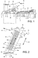
- turbojet 1 with double flow and double body, having a high dilution rate.
- the turbojet 1 conventionally comprises a gas generator 2 on either side of which are arranged a low pressure compressor 4 and a low pressure turbine 12, this gas generator 2 comprising a high pressure compressor 6, a combustion chamber 8 and a high pressure turbine 10.
- the terms “front” and “rear” are considered in a direction 14 opposite to the main flow direction of the gases within the gas. turbojet, this direction 14 being parallel to the longitudinal axis 3 thereof.
- upstream and downstream are considered according to the main flow direction of the gases within the turbojet.
- the low pressure compressor 4 and the low pressure turbine 12 form a low pressure body, and are connected to each other by a low pressure shaft 11 centered on the axis 3.
- the high pressure compressor 6 and the high pressure turbine 10 form a high pressure body, and are connected to each other by a high pressure shaft 13 centered on the axis 3 and arranged around the low pressure shaft 11.
- the shafts are supported by bearings bearing 19, which are lubricated by being arranged in oil chambers. The same is true for the fan hub 17, also supported by rolling bearings 19.
- the turbojet 1 furthermore comprises, at the front of the gas generator 2 and of the low-pressure compressor 4, a single fan 15 which is here arranged directly behind an air inlet cone of the engine.
- the fan 15 is rotatable along axis 3, and surrounded by a fan housing 9. On the figure 1 , it is not driven directly by the low pressure shaft 11, but only driven indirectly by this shaft via a reduction gear 20, which allows it to rotate at a slower speed. Nevertheless, a solution with direct drive of the fan 15, by the low pressure shaft 11, comes within the scope of the invention.
- the turbojet 1 defines a primary stream 16 intended to be traversed by a primary flow, as well as a secondary stream 18 intended to be crossed by a secondary flow located radially outwardly relative to the primary flow, the flow of the blower therefore being divided.
- the secondary stream 18 is delimited radially outwards in part by an outer shell 23, preferably metallic, extending rearwardly the fan casing 9.
- the turbojet 1 is equipped with a set of equipment, for example of the fuel pump, hydraulic pump, alternator, starter, variable-timing stator actuator (VSV), valve actuator type. discharge, or electric power generator. These include a device for lubricating the reducer 20. These devices are driven by an accessory box or AGB (not shown), which is also lubricated.
- VSV variable-timing stator actuator
- stator vanes 24 Downstream of the fan 15, in the secondary stream 18, there is provided a ring of guide vanes which are here outlet guide vanes 24 (or OGV, standing for “Outlet Guide Vane”).
- These stator vanes 24 connect the outer shell 23 to a casing 26 surrounding the low pressure compressor 4. They are circumferentially spaced from each other, and allow the secondary flow to be straightened after it has passed through the fan 15.
- these vanes 24 can also fulfill a structural function, as is the case in the exemplary embodiments which are presently described. They transfer the forces from the reduction gear and the rolling bearings 19 of the drive shafts and the fan hub, to the outer shell 23. Then, these forces can pass through an engine attachment 30 fixed to the shell 23 and connecting the turbojet. to an attachment pylon (not shown) of the aircraft.
- outlet guide vanes 24 provide, in the embodiments which are presently described, a third function of heat exchanger between the secondary air flow passing through the vane ring, and the lubricant circulating inside. These vanes 24.
- the lubricant intended to be cooled by the outlet guide vanes 24 is that used for lubricating the rolling bearings 19, and / or the equipment of the turbojet engine, and / or of the accessory housing, and / or of the engine. reducer 20.
- These vanes 24 thus form part of the fluidic circuit (s) in which the lubricant is circulated in order successively to lubricate the associated element (s), then to be cooled.
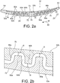
- the blade 24 can be of strictly radial orientation as on the figure 1 , or be slightly inclined axially as shown on the figure 2 . In all cases, it is preferably straight in side view as shown on the figure. figure 2 , extending in a direction of span 25.
- the outlet guide vane 24 comprises an aerodynamic part 32 which corresponds to its central part, that is to say that exposed to the secondary flow.
- the blade 24 On either side of this aerodynamic part 32 serving to straighten the flow leaving the fan, the blade 24 comprises a foot 34 and a head 36 respectively.
- the foot 34 is used for fixing the vane 24 on the casing of the low pressure compressor, while the head is used for fixing this same vane on the outer shell extending the fan housing.
- the blade 24 comprises, at its base and at its head, platforms 40 serving to reconstitute the secondary vein between the blades 24, in the circumferential direction.
- the platforms 40 can be attached between the blades 24.
- the aerodynamic part 32 of the blade is preferably manufactured in two distinct parts, then attached fixedly to one another. It is first of all an extrados body 32a, which includes not only a large part of the aerodynamic part 32, but also the foot 34, the head 36 and the platforms 40.
- This body 32a is made of 'in one piece, for example by foundry then machining.
- the other part is formed by an intrados body 32b, in the form of a cover closing the body 32a fixed to the latter by a conventional technique such as welding, brazing or even gluing.
- the intrados body 32b can also be produced in one piece using conventional techniques, for example also by foundry then machining.
- the aerodynamic part 32 is equipped with two interior passages 50a, 50b substantially parallel to one another, and parallel to the direction of span 25. More precisely, it s This is a first internal lubricant cooling passage 50a, which extends in a first main direction 52a of lubricant flow. This direction 52a is substantially parallel to the direction of span 25, and has a direction going from the foot 34 towards the head 36. Similarly, there is provided a second internal passage 50b for cooling lubricant, which extends along a line. second main direction 52b of flow of the lubricant within this passage. This direction 52b is also substantially parallel to the direction of span 25, and has a reverse direction going from the head 36 to the foot 34.
- the first passage 50a is therefore intended to be crossed. radially outwards by the lubricant, while the second passage 50b is designed to be crossed radially inwards.
- the outer radial ends of the two passages 50a, 50b are fluidly connected by a 180 ° elbow 54, corresponding to a hollow made in the aerodynamic part. 32.
- the passages 50a, 50b do not connect within the aerodynamic part 32 of the vane 24, but each extend separately over the entire length of the aerodynamic part 32.
- a connecting elbow is provided, arranged radially outwardly relative to the blade head 36, for example resting on this head.
- the internal radial ends of the two passages 50a, 50b are for their part connected to the lubricant circuit 56, shown diagrammatically by the element 56 on the figure 2 .
- This circuit 56 comprises in particular a pump (not shown), making it possible to apply to the lubricant the direction of flow desired within the passages 50a, 50b, namely the introduction of the lubricant through the internal radial end of the first passage 50a, and extracting the lubricant from the internal radial end of the second passage 50b.
- Connectors 66 ensure fluid communication between the internal radial ends of the passages 50a, 50b and the circuit 56, these connections 66 passing through the foot 34.
- the two passages 50a, 50b as well as the elbow 54 together have a general U shape, with the first passage 50a and the second passage 50b offset from each other in a transverse direction 60 of the blade substantially orthogonal to the blade. direction of span 25.
- the first passage 50a is located on the side of a trailing edge 62 of the blade 24, while the second passage 50b is located on the side of an edge d 'attack 64.
- an opposite situation can be adopted, without departing from the scope of the invention.
- the invention could provide an aerodynamic part 32 with a single internal cooling passage, without departing from the scope of the invention. In this case, certain blades would be traversed by the lubricant from the inside to the outside, while other blades would be crossed in the opposite direction.
- the extrados body 32a comprises, at the level of the aerodynamic part 32, an extrados surface 72, a solid zone 74 located near the trailing edge 62, a solid zone 76 located near the leading edge 64, as well as a central solid zone 78. These three zones 74, 76, 78 are in contact with the lower surface body 32b, and the two zones 74, 76 have recesses for the support and fixing of this lower surface body. 32b.
- the central zone 78 also serves as a structural reinforcement and extends from the foot 34 to the elbow 54, while the solid zones 74, 76 extend over substantially the entire length of the aerodynamic part 32, in the direction of the span. 25.
- the first passage 50a is formed between the solid areas 74, 78, while the second passage 50b is formed between the solid areas 76, 78.
- the passages 50a, 50b extend transversely in the direction 60 having a variable thickness between the passages.
- two bodies 32a, 32b The maximum thickness of these passages can be of the order of a few millimeters.
- the passages 50a, 50b could have a constant thickness, without departing from the scope of the invention.
- the pressure side body 32b for its part defines the pressure side surface 70, or a large part thereof.
- the two internal passages 50a, 50b for cooling lubricant have the particular feature of integrating flow disrupting pads. These pads are provided on the upper surface body 32a as well as on the lower surface body 32b, and interpenetrate within the passages 50a, 50b, as will be detailed below.
- the arrangement and the shape of the studs are substantially identical or similar in the two passages 50a, 50b. They are also provided in the same densities, although this could be otherwise, without departing from the scope of the invention. Consequently, only the pads of the first interior passage 50a will now be described, but it should be understood that this description is also applicable by analogy to the pads of the second interior passage 50b.
- the elbow 54 defines an interior space which is preferably free of studs.
- first passage 50a there is first of all provided a first series of pads 80a produced in one piece with the extrados body 32a.
- the surface of the body 32a opposite to the upper surface 72 is preferably machined.
- the studs 80a are thus made projecting in the direction of the lower surface body 32b, being substantially orthogonal to direction 52a.
- the height of the pad in the direction of the body 32b is for example of the order of one or more millimeters.
- the pads 80a are provided in a density for example of about 3 pads / cm 2 . More generally, the density is for example between approximately 1 and 5 pads / cm 2 on average.
- the pads 80a can adopt a generally rectangular section as shown in the figure. figure 5 , or oblong as shown on the figure 3 .
- This oblong shape is preferred, in particular when its major axis 81 is arranged parallel to the direction 52a.
- other shapes can be adopted for the section which is preferably substantially identical over the entire height of the stud, such as for example a generally square shape.
- the first series of pads 80a is in the form of a matrix defining first columns of pads CP1, as well as first rows of pads LP1.
- the columns of pads CP1 follow one another in direction 60, while the rows of pads LP1 follow one another in direction 52a.
- the rows and the columns are preferably substantially straight with regular spacings inherent in the shape of the die, which allows simple machining of the pads 80a, by performing parallel and perpendicular passes between them.
- the pads 80a of the first series define between them a first inter-pad space 84a.
- the intrados body 32b As regards the intrados body 32b, a similar embodiment is carried out.
- a second series of studs 80b made in one piece with the pressure side body 32b.
- the studs 80b are thus made to project in the direction of the extrados body 32a, being substantially orthogonal to the direction 52a.
- the height of the stud, the shape and the density are preferably identical or similar to those of the first series of studs 80a.
- the second series of pads 80b is also in the form of a matrix defining second columns of pads CP2, as well as second rows of pads LP2.
- the columns of pads CP2 follow one another in direction 60, while the rows of pads LP2 follow one another in direction 52a.
- the number, shape, composition and the spacing of the rows and columns are preferably identical to those of the first series of pads 80a.
- pads 80b of the second series define between them a second inter-pad space 84b, referenced on the figure 2a .
- One of the other features of the invention lies in the fact that the pads 80a, 80b interpenetrate, that is to say that the pads 80a of the first series penetrate into the second inter-pad space 84b, of even as the pads 80b of the second series enter the first inter-pad space 84a.
- Cooperation between the two bodies 32a, 32b is retained so that all of the pads 80a, 80b, formed by the first and second series, are staggered for better disturbance of the flow of lubricant and increased heat exchange.
- This staggered arrangement is shown on the figure 5 . It is easily obtained by the alternation of first and second columns CP1, CP2, as well as by the alternation of first and second lines LP1, LP2.
- the pitch between the columns may differ from the pitch between the rows, or else this pitch may be identical.
- the pads 80a, 80b do not contact the opposite body 32a, 32b.
- the end of the pads 80a of the first series is located at a distance from the surface of the body 32b from which the pads 80b of the second series protrude, as is the end of these pads 80b. is located at a distance from the surface of the body 32a from which protrude the pads 80a of the first series.
- These spacing distances "D" between the studs and their opposite body have been referenced on the figure 2b .
- These distances are preferably identical, for example from 0.5 to 3 mm. Consequently, the resulting interpenetration of the studs makes it possible to further promote heat exchange, since the lubricant is forced to also move in the direction of the thickness of the blade when it circulates from the foot to the head, which increases the wetted surface.
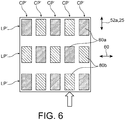
- the relative arrangement of the two matrices of pads 80a, 80b differs from that of the figure 5 . Indeed, if there is always a half-step offset between the two dies in the transverse direction 60, on the other hand, there is no longer any offset in the direction of flow of the flow 52a. Consequently, the pads 80a, 80b of the first and second series of pads are arranged so as to define an alternation between first columns CP1 each produced exclusively with pads 80a of the first series, and second columns CP2 each performed exclusively with pads 80b of the second series.
- first and second lines LP1, LP2 are grouped together two by two so that within the same line LP of this set of pads 80a, 80b also in the form of a matrix, the pads 80a of the first series are arranged alternately with the pads 80b of the second series.
- the pads 80a of the first series are made staggered, just as the pads 80b of the second series are also made staggered.
- the set of pads 80a, 80b forms a matrix with columns of pads CP ', and rows of pads LP'.
- Each row LP ' is formed by the alternation between pads 80a and pads 80b, just as each column CP' is formed by the alternation between pads 80a and pads 80b.
- the lubricant circulating through the circuit 56 is introduced into the first internal passage 50a, in the first direction 52a going radially outwards. At this point, the lubricant has a high temperature. A heat exchange then takes place between this lubricant marrying the pads 80a, 80b of the first passage 50a, and the secondary flow conforming to the outer surface of the intrados and extrados walls. The lubricant, after having been redirected by the elbow 54 in the second passage 50b, undergoes in the latter a similar cooling, again by heat exchange with the secondary air flow and by circulating in the second main flow direction 52b.
- the cooled lubricant is withdrawn from the vane 24, and redirected through the closed circuit 56 to elements to be lubricated and / or to a lubricant reservoir from which cooled lubricant is pumped to lubricate elements.
Landscapes
- Engineering & Computer Science (AREA)
- Mechanical Engineering (AREA)
- General Engineering & Computer Science (AREA)
- Chemical & Material Sciences (AREA)
- Combustion & Propulsion (AREA)
- Physics & Mathematics (AREA)
- Fluid Mechanics (AREA)
- Architecture (AREA)
- Structures Of Non-Positive Displacement Pumps (AREA)
Claims (10)
- Leitschaufel (24), die dazu vorgesehen ist, ganz oder teilweise in einem Luftstrom eines Gebläses (15) eines Zweistrom-Turbotriebwerks eines Luftfahrzeuges angeordnet zu werden, wobei die Leitschaufel einen Fuß (34), einen Kopf (36) sowie einen aerodynamischen Teil (32) zur Gleichrichtung des Stroms aufweist, der zwischen dem Fuß und dem Kopf der Schaufel angeordnet ist, wobei die Schaufel einen saugseitigen Körper (32a), der zumindest einen Teil einer saugseitigen Fläche (72) des aerodynamischen Teils (32) definiert, sowie einen druckseitigen Körper (32b) aufweist, der zumindest einen Teil einer druckseitigen Fläche (70) des aerodynamischen Teils (32) definiert, wobei dieser zumindest einen inneren Kühldurchgang (50a, 50b) für das Schmiermittel aufweist, der mit Störstufen (80a, 80b) des Flusses versehen ist und zumindest teilweise durch den druckseitigen und den saugseitigen Körper begrenzt ist, welche aneinander befestigt sind,
dadurch gekennzeichnet, dass eine erste Reihe von Stufen (80a) einstückig mit dem saugseitigen Körper (32a) ausgeführt ist, wobei die Stufen der ersten Reihe einen ersten Zwischenraum zwischen den Stufen (84a) definieren,
dass eine zweite Reihe von Stufen (80b) einstückig mit dem druckseitigen Körper (32b) ausgeführt ist, wobei die Stufen der zweiten Reihe einen zweiten Zwischenraum zwischen den Stufen (84b) definieren, der von den Stufen (80a) der ersten Reihe durchdrungen wird, während der erste Zwischenraum zwischen den Stufen (84a) von den Stufen (80b) der zweiten Reihe durchdrungen wird,
und dass sich das Ende der Stufen (80a) der ersten Reihe beabstandet von dem druckseitigen Körper (32b) befindet, sowie dass sich das Ende der Stufen (80b) der zweiten Reihe beabstandet von dem saugseitigen Körper (32a) befindet. - Schaufel nach Anspruch 1, dadurch gekennzeichnet, dass die erste und die zweite Reihe von Stufen (80a, 80b) jeweils in Form einer Matrix dargestellt ist, die Linien und Spalten der Stufen definiert (LP1, LP2, CP1, CP2).
- Schaufel nach Anspruch 2, dadurch gekennzeichnet, dass die Stufen (80a, 80b) der ersten und der zweiten Reihe von Stufen versetzt angeordnet sind.
- Schaufel nach Anspruch 2, dadurch gekennzeichnet, dass die Stufen (80a, 80b) der ersten und der zweiten Stufenreihe derart angeordnet sind, dass sie einen Wechsel von Spalten (CP1), die ausschließlich mit Stufen (80a) der ersten Reihe realisiert sind, und von Spalten (CP2) definieren, die ausschließlich mit Stufen (80b) der zweiten Reihe realisiert sind.
- Schaufel nach Anspruch 1, dadurch gekennzeichnet, dass innerhalb jeder der ersten und der zweiten Reihe von Stufen (80a, 80b) die Stufen versetzt angeordnet sind.
- Schaufel nach Anspruch 5, dadurch gekennzeichnet, dass die Stufen (80a, 80b) der ersten und der zweiten Stufenreihe derart angeordnet sind, dass sie zusammen eine Matrix definieren, welche Linien (LP') und Spalten (CP') von Stufen bildet, wobei jede der Linien und Spalten der Matrix durch den Wechsel der Stufen (80a) der ersten Reihe und der Stufen (80b) der zweiten Reihe realisiert wird.
- Schaufel nach einem der vorhergehenden Ansprüche, dadurch gekennzeichnet, dass jede Stufe (80a, 80b) einen allgemein kreisförmigen, länglichen, quadratischen oder rechteckigen Querschnitt aufweist.
- Schaufel nach einem der vorhergehenden Ansprüche, dadurch gekennzeichnet, dass jede Stufe (80a, 80b) einen allgemein länglichen Querschnitt aufweist, wobei die Hauptachse (81) parallel zu einer Hauptfließrichtung des Schmiermittels (52a) in dem Kühldurchgang (50a) angeordnet ist.
- Turbotriebwerk (1) eines Luftfahrzeugs, vorzugsweise ein Turboluftstrahltriebwerk, mit einer Mehrzahl von Leitschaufeln (24) nach einem der vorhergehenden Ansprüche, die einem Gebläse (15) des Turbotriebwerks nachgelagert oder vorgelagert sind.
- Herstellungsverfahren einer Leitschaufel (24) nach einem der Ansprüche 1 bis 8, dadurch gekennzeichnet, dass es einen Schritt zur Bereitstellung der Stufen (80a, 80b) durch Bearbeitung der saugseitigen und der druckseitigen Körper (32a, 32b) umfasst.
Applications Claiming Priority (1)
| Application Number | Priority Date | Filing Date | Title |
|---|---|---|---|
| FR1762405A FR3075256B1 (fr) | 2017-12-19 | 2017-12-19 | Aube directrice de sortie pour turbomachine d'aeronef, comprenant un passage de refroidissement de lubrifiant equipe de plots perturbateurs de flux |
Publications (2)
| Publication Number | Publication Date |
|---|---|
| EP3508701A1 EP3508701A1 (de) | 2019-07-10 |
| EP3508701B1 true EP3508701B1 (de) | 2021-03-03 |
Family
ID=61224129
Family Applications (1)
| Application Number | Title | Priority Date | Filing Date |
|---|---|---|---|
| EP18213732.3A Active EP3508701B1 (de) | 2017-12-19 | 2018-12-18 | Austrittsleitschaufel für turbotriebwerk eines luftfahrzeugs, die einen kühldurchgang für das schmiermittel umfasst, der mit störstufen des flusses ausgestattet ist |
Country Status (3)
| Country | Link |
|---|---|
| US (1) | US10883382B2 (de) |
| EP (1) | EP3508701B1 (de) |
| FR (1) | FR3075256B1 (de) |
Families Citing this family (11)
| Publication number | Priority date | Publication date | Assignee | Title |
|---|---|---|---|---|
| FR3059353B1 (fr) * | 2016-11-29 | 2019-05-17 | Safran Aircraft Engines | Aube directrice de sortie pour turbomachine d'aeronef, comprenant une zone coudee de passage de lubrifiant presentant une conception amelioree |
| FR3066532B1 (fr) * | 2017-05-22 | 2019-07-12 | Safran Aircraft Engines | Aube directrice de sortie pour turbomachine d'aeronef, comprenant un passage de refroidissement de lubrifiant equipe de plots perturbateurs de flux a fabrication simplifiee |
| FR3081912B1 (fr) | 2018-05-29 | 2020-09-04 | Safran Aircraft Engines | Aube de turbomachine comprenant un passage interne d'ecoulement de fluide equipe d'une pluralite d'elements perturbateurs a agencement optimise |
| GB2591298B (en) * | 2020-01-27 | 2022-06-08 | Gkn Aerospace Sweden Ab | Outlet guide vane cooler |
| GB2599689A (en) * | 2020-10-09 | 2022-04-13 | Rolls Royce Plc | An improved turbofan gas turbine engine |
| US12055098B2 (en) * | 2021-07-09 | 2024-08-06 | Rtx Corporation | Hydrogen powered engine with exhaust heat exchanger |
| US20240247593A1 (en) * | 2023-01-25 | 2024-07-25 | Raytheon Technologies Corporation | Two piece hollow-vane assembly joined via brazing |
| US20240309764A1 (en) * | 2023-03-14 | 2024-09-19 | Raytheon Technologies Corporation | Altering structural response of two-piece hollow-vane assembly |
| US12110807B1 (en) | 2023-03-14 | 2024-10-08 | Rtx Corporation | Altering structural response of two-piece hollow-vane assembly by changing the cover composition |
| DE102023108541A1 (de) * | 2023-04-04 | 2024-10-10 | MTU Aero Engines AG | Verfahren zur Herstellung einer Leitschaufel, sowie zugehörige Leitschaufel |
| FR3148258A1 (fr) * | 2023-04-28 | 2024-11-01 | Safran Aircraft Engines | Carter pour une turbomachine d’aeronef |
Family Cites Families (11)
| Publication number | Priority date | Publication date | Assignee | Title |
|---|---|---|---|---|
| US4914904A (en) * | 1988-11-09 | 1990-04-10 | Avco Corporation | Oil cooler for fan jet engines |
| US7377098B2 (en) * | 2004-08-26 | 2008-05-27 | United Technologies Corporation | Gas turbine engine frame with an integral fluid reservoir and air/fluid heat exchanger |
| US8616834B2 (en) * | 2010-04-30 | 2013-12-31 | General Electric Company | Gas turbine engine airfoil integrated heat exchanger |
| US20140328669A1 (en) * | 2011-11-25 | 2014-11-06 | Siemens Aktiengesellschaft | Airfoil with cooling passages |
| FR2989110B1 (fr) * | 2012-04-05 | 2016-09-09 | Snecma | Aube de stator formee par un ensemble de parties d'aube |
| US9470095B2 (en) * | 2012-04-24 | 2016-10-18 | United Technologies Corporation | Airfoil having internal lattice network |
| FR3046811B1 (fr) | 2016-01-15 | 2018-02-16 | Snecma | Aube directrice de sortie pour turbomachine d'aeronef, presentant une fonction amelioree de refroidissement de lubrifiant |
| FR3054263B1 (fr) * | 2016-07-20 | 2018-08-10 | Safran Aircraft Engines | Carter intermediaire de turbomachine d'aeronef realise d'une seule piece de fonderie avec une canalisation de lubrifiant |
| FR3063767B1 (fr) * | 2017-03-13 | 2019-04-26 | Safran Aircraft Engines | Aube directrice de sortie pour turbomachine d'aeronef, a fonction amelioree de refroidissement de lubrifiant |
| FR3064682B1 (fr) * | 2017-03-31 | 2019-06-14 | Safran Aircraft Engines | Carter intermediaire de turbomachine d'aeronef comprenant un embout de passage de lubrifiant connecte a une aube de carter par une piece de raccord |
| FR3071008B1 (fr) * | 2017-09-11 | 2019-09-13 | Safran Aircraft Engines | Aube directrice de sortie pour turbomachine, comprenant un passage de refroidissement de lubrifiant equipe d'une matrice de conduction thermique comprimee entre les parois d'intrados et d'extrados |
-
2017
- 2017-12-19 FR FR1762405A patent/FR3075256B1/fr not_active Expired - Fee Related
-
2018
- 2018-12-17 US US16/222,020 patent/US10883382B2/en active Active
- 2018-12-18 EP EP18213732.3A patent/EP3508701B1/de active Active
Non-Patent Citations (1)
| Title |
|---|
| None * |
Also Published As
| Publication number | Publication date |
|---|---|
| US10883382B2 (en) | 2021-01-05 |
| EP3508701A1 (de) | 2019-07-10 |
| US20190186293A1 (en) | 2019-06-20 |
| FR3075256B1 (fr) | 2020-01-10 |
| FR3075256A1 (fr) | 2019-06-21 |
Similar Documents
| Publication | Publication Date | Title |
|---|---|---|
| EP3508701B1 (de) | Austrittsleitschaufel für turbotriebwerk eines luftfahrzeugs, die einen kühldurchgang für das schmiermittel umfasst, der mit störstufen des flusses ausgestattet ist | |
| EP3610134B1 (de) | Leitschaufel, zugehörige strömungsmaschine und herstellungsverfahren | |
| FR3071008B1 (fr) | Aube directrice de sortie pour turbomachine, comprenant un passage de refroidissement de lubrifiant equipe d'une matrice de conduction thermique comprimee entre les parois d'intrados et d'extrados | |
| EP3548706B1 (de) | Austrittsleitschaufel einer turbomaschine eines flugzeugs mit einem gebogenen schmierkanal mit verbessertem design | |
| FR3049644A1 (fr) | Aube directrice de sortie pour turbomachine d'aeronef, presentant une fonction amelioree de refroidissement de lubrifiant a l'aide d'une matrice de conduction thermique logee dans un passage interieur de l'aube | |
| FR3046811A1 (fr) | Aube directrice de sortie pour turbomachine d'aeronef, presentant une fonction amelioree de refroidissement de lubrifiant | |
| FR3063767A1 (fr) | Aube directrice de sortie pour turbomachine d'aeronef, a fonction amelioree de refroidissement de lubrifiant | |
| EP1413771B1 (de) | Gehäuse, Verdichter, Turbine und Triebwerk mit einem solchen Gehäuse | |
| EP2339123A1 (de) | Innere Seite des Mantels des Sekundärstromes eines Turbostrahltriebwerkes und Verfahren zur Montage eines solchen Mantels | |
| FR3077850A1 (fr) | Aube directrice de sortie pour turbomachine, realisee a partir de plusieurs pieces assemblees entre elles par des moyens de fixation deportes de la veine | |
| EP3775497B1 (de) | Turbomaschinenschaufel mit einem inneren strömungskanal mit einer vielzahl von optimal angeordneten störelementen | |
| WO2013150248A1 (fr) | Aubage de redressement de sortie | |
| FR2989110A1 (fr) | Aube de stator formee par un ensemble de parties d'aube | |
| FR3054263A1 (fr) | Carter intermediaire de turbomachine d'aeronef realise d'une seule piece de fonderie avec une canalisation de lubrifiant | |
| FR3109962A1 (fr) | Aube directrice de sortie pour turbomachine d’aeronef, comprenant un passage de refroidissement de lubrifiant equipe de parois ondulees | |
| EP3906359B1 (de) | Schaufelblatt für ein turbinentriebwerk | |
| FR2989108A1 (fr) | Partie de stator comportant une aube de stator et une structure de conduction thermique | |
| EP4374047A1 (de) | Turbinentriebwerk für ein flugzeug mit wärmetauscher | |
| FR3110630A1 (fr) | Aube directrice de sortie pour turbomachine, realisee a partir de plusieurs pieces assemblees entre elles | |
| FR3093765A1 (fr) | Systeme echangeur de chaleur air-huile de turbomachine optimise | |
| FR3064295B1 (fr) | Carter intermediaire de turbomachine d'aeronef comprenant un embout de passage de lubrifiant solidaire d'une plateforme | |
| EP4055261B1 (de) | Wärmetauscher, der eine mit hohlen turbulenzgeneratoren versehene zwischenwand umfasst | |
| FR3064296B1 (fr) | Carter intermediaire de turbomachine d'aeronef comprenant une piece intermediaire entre un pied d'aube et le moyeu | |
| EP4374046A1 (de) | Turbinentriebwerk für ein flugzeug mit wärmetauscher | |
| FR3140122A1 (fr) | Ensemble pour turbomachine d’aeronef comprenant un echangeur de chaleur du type sacoc, de conception ameliore |
Legal Events
| Date | Code | Title | Description |
|---|---|---|---|
| PUAI | Public reference made under article 153(3) epc to a published international application that has entered the european phase |
Free format text: ORIGINAL CODE: 0009012 |
|
| STAA | Information on the status of an ep patent application or granted ep patent |
Free format text: STATUS: THE APPLICATION HAS BEEN PUBLISHED |
|
| AK | Designated contracting states |
Kind code of ref document: A1 Designated state(s): AL AT BE BG CH CY CZ DE DK EE ES FI FR GB GR HR HU IE IS IT LI LT LU LV MC MK MT NL NO PL PT RO RS SE SI SK SM TR |
|
| AX | Request for extension of the european patent |
Extension state: BA ME |
|
| STAA | Information on the status of an ep patent application or granted ep patent |
Free format text: STATUS: REQUEST FOR EXAMINATION WAS MADE |
|
| 17P | Request for examination filed |
Effective date: 20190806 |
|
| RBV | Designated contracting states (corrected) |
Designated state(s): AL AT BE BG CH CY CZ DE DK EE ES FI FR GB GR HR HU IE IS IT LI LT LU LV MC MK MT NL NO PL PT RO RS SE SI SK SM TR |
|
| GRAP | Despatch of communication of intention to grant a patent |
Free format text: ORIGINAL CODE: EPIDOSNIGR1 |
|
| STAA | Information on the status of an ep patent application or granted ep patent |
Free format text: STATUS: GRANT OF PATENT IS INTENDED |
|
| INTG | Intention to grant announced |
Effective date: 20200925 |
|
| GRAS | Grant fee paid |
Free format text: ORIGINAL CODE: EPIDOSNIGR3 |
|
| STAA | Information on the status of an ep patent application or granted ep patent |
Free format text: STATUS: GRANT OF PATENT IS INTENDED |
|
| GRAA | (expected) grant |
Free format text: ORIGINAL CODE: 0009210 |
|
| STAA | Information on the status of an ep patent application or granted ep patent |
Free format text: STATUS: THE PATENT HAS BEEN GRANTED |
|
| AK | Designated contracting states |
Kind code of ref document: B1 Designated state(s): AL AT BE BG CH CY CZ DE DK EE ES FI FR GB GR HR HU IE IS IT LI LT LU LV MC MK MT NL NO PL PT RO RS SE SI SK SM TR |
|
| REG | Reference to a national code |
Ref country code: GB Ref legal event code: FG4D Free format text: NOT ENGLISH |
|
| REG | Reference to a national code |
Ref country code: AT Ref legal event code: REF Ref document number: 1367425 Country of ref document: AT Kind code of ref document: T Effective date: 20210315 Ref country code: CH Ref legal event code: EP |
|
| REG | Reference to a national code |
Ref country code: DE Ref legal event code: R096 Ref document number: 602018013336 Country of ref document: DE |
|
| REG | Reference to a national code |
Ref country code: IE Ref legal event code: FG4D Free format text: LANGUAGE OF EP DOCUMENT: FRENCH |
|
| REG | Reference to a national code |
Ref country code: LT Ref legal event code: MG9D |
|
| PG25 | Lapsed in a contracting state [announced via postgrant information from national office to epo] |
Ref country code: HR Free format text: LAPSE BECAUSE OF FAILURE TO SUBMIT A TRANSLATION OF THE DESCRIPTION OR TO PAY THE FEE WITHIN THE PRESCRIBED TIME-LIMIT Effective date: 20210303 Ref country code: GR Free format text: LAPSE BECAUSE OF FAILURE TO SUBMIT A TRANSLATION OF THE DESCRIPTION OR TO PAY THE FEE WITHIN THE PRESCRIBED TIME-LIMIT Effective date: 20210604 Ref country code: FI Free format text: LAPSE BECAUSE OF FAILURE TO SUBMIT A TRANSLATION OF THE DESCRIPTION OR TO PAY THE FEE WITHIN THE PRESCRIBED TIME-LIMIT Effective date: 20210303 Ref country code: BG Free format text: LAPSE BECAUSE OF FAILURE TO SUBMIT A TRANSLATION OF THE DESCRIPTION OR TO PAY THE FEE WITHIN THE PRESCRIBED TIME-LIMIT Effective date: 20210603 Ref country code: NO Free format text: LAPSE BECAUSE OF FAILURE TO SUBMIT A TRANSLATION OF THE DESCRIPTION OR TO PAY THE FEE WITHIN THE PRESCRIBED TIME-LIMIT Effective date: 20210603 Ref country code: LT Free format text: LAPSE BECAUSE OF FAILURE TO SUBMIT A TRANSLATION OF THE DESCRIPTION OR TO PAY THE FEE WITHIN THE PRESCRIBED TIME-LIMIT Effective date: 20210303 |
|
| REG | Reference to a national code |
Ref country code: NL Ref legal event code: MP Effective date: 20210303 |
|
| REG | Reference to a national code |
Ref country code: AT Ref legal event code: MK05 Ref document number: 1367425 Country of ref document: AT Kind code of ref document: T Effective date: 20210303 |
|
| PG25 | Lapsed in a contracting state [announced via postgrant information from national office to epo] |
Ref country code: PL Free format text: LAPSE BECAUSE OF FAILURE TO SUBMIT A TRANSLATION OF THE DESCRIPTION OR TO PAY THE FEE WITHIN THE PRESCRIBED TIME-LIMIT Effective date: 20210303 Ref country code: RS Free format text: LAPSE BECAUSE OF FAILURE TO SUBMIT A TRANSLATION OF THE DESCRIPTION OR TO PAY THE FEE WITHIN THE PRESCRIBED TIME-LIMIT Effective date: 20210303 Ref country code: LV Free format text: LAPSE BECAUSE OF FAILURE TO SUBMIT A TRANSLATION OF THE DESCRIPTION OR TO PAY THE FEE WITHIN THE PRESCRIBED TIME-LIMIT Effective date: 20210303 Ref country code: SE Free format text: LAPSE BECAUSE OF FAILURE TO SUBMIT A TRANSLATION OF THE DESCRIPTION OR TO PAY THE FEE WITHIN THE PRESCRIBED TIME-LIMIT Effective date: 20210303 |
|
| PG25 | Lapsed in a contracting state [announced via postgrant information from national office to epo] |
Ref country code: NL Free format text: LAPSE BECAUSE OF FAILURE TO SUBMIT A TRANSLATION OF THE DESCRIPTION OR TO PAY THE FEE WITHIN THE PRESCRIBED TIME-LIMIT Effective date: 20210303 |
|
| PG25 | Lapsed in a contracting state [announced via postgrant information from national office to epo] |
Ref country code: AT Free format text: LAPSE BECAUSE OF FAILURE TO SUBMIT A TRANSLATION OF THE DESCRIPTION OR TO PAY THE FEE WITHIN THE PRESCRIBED TIME-LIMIT Effective date: 20210303 Ref country code: SM Free format text: LAPSE BECAUSE OF FAILURE TO SUBMIT A TRANSLATION OF THE DESCRIPTION OR TO PAY THE FEE WITHIN THE PRESCRIBED TIME-LIMIT Effective date: 20210303 Ref country code: EE Free format text: LAPSE BECAUSE OF FAILURE TO SUBMIT A TRANSLATION OF THE DESCRIPTION OR TO PAY THE FEE WITHIN THE PRESCRIBED TIME-LIMIT Effective date: 20210303 Ref country code: CZ Free format text: LAPSE BECAUSE OF FAILURE TO SUBMIT A TRANSLATION OF THE DESCRIPTION OR TO PAY THE FEE WITHIN THE PRESCRIBED TIME-LIMIT Effective date: 20210303 |
|
| PG25 | Lapsed in a contracting state [announced via postgrant information from national office to epo] |
Ref country code: IS Free format text: LAPSE BECAUSE OF FAILURE TO SUBMIT A TRANSLATION OF THE DESCRIPTION OR TO PAY THE FEE WITHIN THE PRESCRIBED TIME-LIMIT Effective date: 20210703 Ref country code: PT Free format text: LAPSE BECAUSE OF FAILURE TO SUBMIT A TRANSLATION OF THE DESCRIPTION OR TO PAY THE FEE WITHIN THE PRESCRIBED TIME-LIMIT Effective date: 20210705 Ref country code: SK Free format text: LAPSE BECAUSE OF FAILURE TO SUBMIT A TRANSLATION OF THE DESCRIPTION OR TO PAY THE FEE WITHIN THE PRESCRIBED TIME-LIMIT Effective date: 20210303 Ref country code: RO Free format text: LAPSE BECAUSE OF FAILURE TO SUBMIT A TRANSLATION OF THE DESCRIPTION OR TO PAY THE FEE WITHIN THE PRESCRIBED TIME-LIMIT Effective date: 20210303 |
|
| REG | Reference to a national code |
Ref country code: DE Ref legal event code: R097 Ref document number: 602018013336 Country of ref document: DE |
|
| PLBE | No opposition filed within time limit |
Free format text: ORIGINAL CODE: 0009261 |
|
| STAA | Information on the status of an ep patent application or granted ep patent |
Free format text: STATUS: NO OPPOSITION FILED WITHIN TIME LIMIT |
|
| PG25 | Lapsed in a contracting state [announced via postgrant information from national office to epo] |
Ref country code: ES Free format text: LAPSE BECAUSE OF FAILURE TO SUBMIT A TRANSLATION OF THE DESCRIPTION OR TO PAY THE FEE WITHIN THE PRESCRIBED TIME-LIMIT Effective date: 20210303 Ref country code: DK Free format text: LAPSE BECAUSE OF FAILURE TO SUBMIT A TRANSLATION OF THE DESCRIPTION OR TO PAY THE FEE WITHIN THE PRESCRIBED TIME-LIMIT Effective date: 20210303 Ref country code: AL Free format text: LAPSE BECAUSE OF FAILURE TO SUBMIT A TRANSLATION OF THE DESCRIPTION OR TO PAY THE FEE WITHIN THE PRESCRIBED TIME-LIMIT Effective date: 20210303 |
|
| 26N | No opposition filed |
Effective date: 20211206 |
|
| PG25 | Lapsed in a contracting state [announced via postgrant information from national office to epo] |
Ref country code: SI Free format text: LAPSE BECAUSE OF FAILURE TO SUBMIT A TRANSLATION OF THE DESCRIPTION OR TO PAY THE FEE WITHIN THE PRESCRIBED TIME-LIMIT Effective date: 20210303 |
|
| PG25 | Lapsed in a contracting state [announced via postgrant information from national office to epo] |
Ref country code: IT Free format text: LAPSE BECAUSE OF FAILURE TO SUBMIT A TRANSLATION OF THE DESCRIPTION OR TO PAY THE FEE WITHIN THE PRESCRIBED TIME-LIMIT Effective date: 20210303 |
|
| PG25 | Lapsed in a contracting state [announced via postgrant information from national office to epo] |
Ref country code: IS Free format text: LAPSE BECAUSE OF FAILURE TO SUBMIT A TRANSLATION OF THE DESCRIPTION OR TO PAY THE FEE WITHIN THE PRESCRIBED TIME-LIMIT Effective date: 20210703 |
|
| PG25 | Lapsed in a contracting state [announced via postgrant information from national office to epo] |
Ref country code: MC Free format text: LAPSE BECAUSE OF FAILURE TO SUBMIT A TRANSLATION OF THE DESCRIPTION OR TO PAY THE FEE WITHIN THE PRESCRIBED TIME-LIMIT Effective date: 20210303 |
|
| REG | Reference to a national code |
Ref country code: CH Ref legal event code: PL |
|
| REG | Reference to a national code |
Ref country code: BE Ref legal event code: MM Effective date: 20211231 |
|
| PG25 | Lapsed in a contracting state [announced via postgrant information from national office to epo] |
Ref country code: LU Free format text: LAPSE BECAUSE OF NON-PAYMENT OF DUE FEES Effective date: 20211218 Ref country code: IE Free format text: LAPSE BECAUSE OF NON-PAYMENT OF DUE FEES Effective date: 20211218 |
|
| PG25 | Lapsed in a contracting state [announced via postgrant information from national office to epo] |
Ref country code: BE Free format text: LAPSE BECAUSE OF NON-PAYMENT OF DUE FEES Effective date: 20211231 |
|
| PG25 | Lapsed in a contracting state [announced via postgrant information from national office to epo] |
Ref country code: LI Free format text: LAPSE BECAUSE OF NON-PAYMENT OF DUE FEES Effective date: 20211231 Ref country code: CH Free format text: LAPSE BECAUSE OF NON-PAYMENT OF DUE FEES Effective date: 20211231 |
|
| PG25 | Lapsed in a contracting state [announced via postgrant information from national office to epo] |
Ref country code: CY Free format text: LAPSE BECAUSE OF FAILURE TO SUBMIT A TRANSLATION OF THE DESCRIPTION OR TO PAY THE FEE WITHIN THE PRESCRIBED TIME-LIMIT Effective date: 20210303 |
|
| PG25 | Lapsed in a contracting state [announced via postgrant information from national office to epo] |
Ref country code: HU Free format text: LAPSE BECAUSE OF FAILURE TO SUBMIT A TRANSLATION OF THE DESCRIPTION OR TO PAY THE FEE WITHIN THE PRESCRIBED TIME-LIMIT; INVALID AB INITIO Effective date: 20181218 |
|
| PGFP | Annual fee paid to national office [announced via postgrant information from national office to epo] |
Ref country code: GB Payment date: 20231121 Year of fee payment: 6 |
|
| PGFP | Annual fee paid to national office [announced via postgrant information from national office to epo] |
Ref country code: FR Payment date: 20231122 Year of fee payment: 6 Ref country code: DE Payment date: 20231121 Year of fee payment: 6 |
|
| PG25 | Lapsed in a contracting state [announced via postgrant information from national office to epo] |
Ref country code: MK Free format text: LAPSE BECAUSE OF FAILURE TO SUBMIT A TRANSLATION OF THE DESCRIPTION OR TO PAY THE FEE WITHIN THE PRESCRIBED TIME-LIMIT Effective date: 20210303 |
|
| PG25 | Lapsed in a contracting state [announced via postgrant information from national office to epo] |
Ref country code: MT Free format text: LAPSE BECAUSE OF FAILURE TO SUBMIT A TRANSLATION OF THE DESCRIPTION OR TO PAY THE FEE WITHIN THE PRESCRIBED TIME-LIMIT Effective date: 20210303 |