EP3775432B1 - System und verfahren zur vorfertigung und verlegung der abdeckung einer raumfläche - Google Patents
System und verfahren zur vorfertigung und verlegung der abdeckung einer raumfläche Download PDFInfo
- Publication number
- EP3775432B1 EP3775432B1 EP19715594.8A EP19715594A EP3775432B1 EP 3775432 B1 EP3775432 B1 EP 3775432B1 EP 19715594 A EP19715594 A EP 19715594A EP 3775432 B1 EP3775432 B1 EP 3775432B1
- Authority
- EP
- European Patent Office
- Prior art keywords
- digital
- room
- plates
- plate
- individual
- Prior art date
- Legal status (The legal status is an assumption and is not a legal conclusion. Google has not performed a legal analysis and makes no representation as to the accuracy of the status listed.)
- Active
Links
Images



Classifications
-
- G—PHYSICS
- G05—CONTROLLING; REGULATING
- G05B—CONTROL OR REGULATING SYSTEMS IN GENERAL; FUNCTIONAL ELEMENTS OF SUCH SYSTEMS; MONITORING OR TESTING ARRANGEMENTS FOR SUCH SYSTEMS OR ELEMENTS
- G05B19/00—Program-control systems
- G05B19/02—Program-control systems electric
- G05B19/18—Numerical control [NC], i.e. automatically operating machines, in particular machine tools, e.g. in a manufacturing environment, so as to execute positioning, movement or co-ordinated operations by means of program data in numerical form
- G05B19/4097—Numerical control [NC], i.e. automatically operating machines, in particular machine tools, e.g. in a manufacturing environment, so as to execute positioning, movement or co-ordinated operations by means of program data in numerical form characterised by using design data to control NC machines, e.g. CAD/CAM
-
- E—FIXED CONSTRUCTIONS
- E04—BUILDING
- E04F—FINISHING WORK ON BUILDINGS, e.g. STAIRS, FLOORS
- E04F15/00—Flooring
- E04F15/02—Flooring or floor layers composed of a number of similar elements
- E04F15/02177—Floor elements for use at a specific location
- E04F15/02188—Floor elements for use at a specific location for use in wet rooms
-
- G—PHYSICS
- G05—CONTROLLING; REGULATING
- G05B—CONTROL OR REGULATING SYSTEMS IN GENERAL; FUNCTIONAL ELEMENTS OF SUCH SYSTEMS; MONITORING OR TESTING ARRANGEMENTS FOR SUCH SYSTEMS OR ELEMENTS
- G05B19/00—Program-control systems
- G05B19/02—Program-control systems electric
- G05B19/18—Numerical control [NC], i.e. automatically operating machines, in particular machine tools, e.g. in a manufacturing environment, so as to execute positioning, movement or co-ordinated operations by means of program data in numerical form
- G05B19/4093—Numerical control [NC], i.e. automatically operating machines, in particular machine tools, e.g. in a manufacturing environment, so as to execute positioning, movement or co-ordinated operations by means of program data in numerical form characterised by part programming, e.g. entry of geometrical information as taken from a technical drawing, combining this with machining and material information to obtain control information, named part program, for the NC machine
-
- G—PHYSICS
- G06—COMPUTING OR CALCULATING; COUNTING
- G06F—ELECTRIC DIGITAL DATA PROCESSING
- G06F30/00—Computer-aided design [CAD]
- G06F30/10—Geometric CAD
- G06F30/17—Mechanical parametric or variational design
-
- E—FIXED CONSTRUCTIONS
- E04—BUILDING
- E04F—FINISHING WORK ON BUILDINGS, e.g. STAIRS, FLOORS
- E04F15/00—Flooring
- E04F15/02—Flooring or floor layers composed of a number of similar elements
- E04F15/08—Flooring or floor layers composed of a number of similar elements only of stone or stone-like material, e.g. ceramics, concrete; of glass or with a top layer of stone or stone-like material, e.g. ceramics, concrete or glass
-
- E—FIXED CONSTRUCTIONS
- E04—BUILDING
- E04F—FINISHING WORK ON BUILDINGS, e.g. STAIRS, FLOORS
- E04F15/00—Flooring
- E04F15/02—Flooring or floor layers composed of a number of similar elements
- E04F15/10—Flooring or floor layers composed of a number of similar elements of other materials, e.g. fibrous or chipped materials, organic plastics, magnesite tiles, hardboard, or with a top layer of other materials
-
- Y—GENERAL TAGGING OF NEW TECHNOLOGICAL DEVELOPMENTS; GENERAL TAGGING OF CROSS-SECTIONAL TECHNOLOGIES SPANNING OVER SEVERAL SECTIONS OF THE IPC; TECHNICAL SUBJECTS COVERED BY FORMER USPC CROSS-REFERENCE ART COLLECTIONS [XRACs] AND DIGESTS
- Y02—TECHNOLOGIES OR APPLICATIONS FOR MITIGATION OR ADAPTATION AGAINST CLIMATE CHANGE
- Y02P—CLIMATE CHANGE MITIGATION TECHNOLOGIES IN THE PRODUCTION OR PROCESSING OF GOODS
- Y02P90/00—Enabling technologies with a potential contribution to greenhouse gas [GHG] emissions mitigation
- Y02P90/02—Total factory control, e.g. smart factories, flexible manufacturing systems [FMS] or integrated manufacturing systems [IMS]
Definitions
- the invention relates to a system and method for pre-fabrication of plates/boards/tiles and laying out of them for covering at least a part of a surface of a room, which surface is at least a part of the inner floor, the inner wall and/or the inner roof or ceiling of the room.
- the room could be a so called wet room, such as a bathroom or the like, or any other room in a house/residence.
- One common known way of laying out coverage on a surface is to adapt the underlay "in-situ", such as the floor in a bathroom by first cleaning the floor and then apply different materials, often flowable putty that is poured out onto the floor. Then, a case putty is performed by use of a screed to form the floor putty into correct shape and desired sloping manually to fulfil current building regulations, and adapting the solidifying putty in relation to any present water in- and outlets, drainage, shower baths in the room and adjusting levels of the floor in regard of adjacent spaces or rooms.
- Levelling of floors before putting on putty is often done using laser equipment and/or spirit levels and appropriate distribution of levelling sticks manually over the floor, the sticks are cut into correct levels or heights.
- the putty is often mixed with water in buckets and poured out on the floor surface and smoothed/shaped manually with the screed. This way of working is done in principle in the same way independently of putting the putty onto a concrete floor or a wooden one. The difference is putty thickness and use of armouring/reinforcing by means of fibreglass mesh or metal mesh for wooden floors.
- Different coverage materials are used, e.g. plastic mats laid onto the floor by gluing onto the putty, plates or boards of wood and/or wood chips/flakes/particles are laid directly on the putty or on scantling laid on the putty or clinker or ceramic/stone tiles are laid onto tile adhesive put on the putty.
- plastic mats laid onto the floor by gluing onto the putty plates or boards of wood and/or wood chips/flakes/particles are laid directly on the putty or on scantling laid on the putty or clinker or ceramic/stone tiles are laid onto tile adhesive put on the putty.
- Known ways of providing coverage on a surface are disclosed in GB 2 437 370 A , US 2015/315773 A1 , and WO 2018/009985 A1 .
- the work environment is tough and a heavy burden for the workers as several tons of putty mixed with water are carried daily wearing out the operators meaning that many of them are not able to work until they reach retirement, at least not full time. Many operators also get occupational injuries that make them unable to work from time to time.
- One object of the present invention is to provide a system and method for coverage of at least a part of an inner surface of a room, preferably a wet room, such as a bathroom or the like, by means of a plurality of pre-fabricated and laid out plates or boards or tiles that solve or at least reduce or diminish the above problems.
- An object of the present invention is to provide a system and method for coverage of at least a part of an inner surface of a wet room, such as a bathroom or the like, by means of a plurality of pre-fabricated and then laid out plates or boards or tiles of which at least one plate or board or tile is preformed by being processed on the underside to be adapted to and to fit against an upper surface of the inner room surface to level out any unevenness of the upper inner room surface that it thereafter covers after layout and at least one other plate or board or tile of this plurality of pre-fabricated and then laid out plates or boards or tiles is also preformed by being processed on both its underside and its upper side to be adapted to and to fit against an upper surface of the inner room surface to level out any unevenness of the upper inner room surface that it thereafter covers after layout and simultaneously to achieve an inclination/slope/rake at/on its upper side after layout to create an inclination/slope/rake of the upper inner room surface that it covers/forms after layout to fulfil standards of wet room drainage or outflow
- the present invention enables laying out of preformed plates or boards or tiles that form a 3D puzzle both horizontally and vertically fulfilling levelling out unevenness of inner wet room surfaces while creating correct inclination/slope/rake of the upper inner wet room surface after layout to a finished wet room surface to secure allowed/sufficient wet room drainage/water outflow.
- An object of the present invention is to provide a system and method for coverage of at least a part of an inner surface of a wet room, such as a bathroom or the like, by means of a plurality of pre-fabricated and then laid out plates or boards or tiles of which at least one plate/board or tile is preformed by being processed on all sides except its upper side to be adapted to and to fit against an upper surface of the inner room surface to level out any unevenness of the upper inner room surface that it thereafter covers after layout and be fitted to adjacent other laid out plates or boards or tiles and at least one other plate or board/tile of this plurality of pre-fabricated and then laid out plates/boards or tiles is also preformed by being processed on all its sides, including its underside and its upper side, to be adapted to and to fit against an upper surface of the inner room surface to level out any unevenness of the upper inner room surface that it thereafter covers with its underside after layout and be fitted to adjacent other laid out plates or boards/tiles and simultaneously to achieve an inclination/slope/rake at/on its upper
- Yet an object of the present invention is to enable laying out of preformed plates or boards or tiles in a 3D puzzle both horizontally to fit against other such preformed plates or boards or tiles or walls or the like of the inner wet room and vertically to level out unevenness in the upper surface of the inner wet room and at the same time, if required at that area and/or the full area of the wet room, to achieve/create/secure an inclination/slope/rake of the wet room surface that it covers/forms after layout to fulfil standards of wet room drainage and water outflow, at least in Sweden but also according to other national regulations for making wet rooms.
- Another object of the present invention is to provide a system and method for coverage of at least a part of an inner surface of a wet room by means of a plurality of pre-fabricated and laid out plates or boards or tiles that accomplish easier handling and working by reducing the heavy burden on the operator and cumbersome working posture of the operator before, during and after performing the coverage of the room surface.
- Yet another object of the present invention is to provide a system and method for coverage of at least a part of an inner surface of a wet room by means of a plurality of pre-fabricated and laid out plates or boards or tiles that enables a more efficient and quicker way of working before, during and after coverage of the room surface accordingly.
- Still another object of the present invention is to provide a system and method for coverage of at least a part of an inner surface of a wet room by means of a plurality of pre-fabricated and laid out plates or boards or tiles that provides a better reproducibility in regard of quality of work and final result for each room surface coverage before, during and after the work and in a more simplified way reducing the need of experience and training for the work and also facilitates the control of the final result.
- One more object of the present invention is to provide a system and method for coverage of at least a part of an inner surface of a wet room by means of a plurality of pre-fabricated and laid out plates or boards or tiles that enables more predictable planning and possibility of such work further away and at different sites with even unexperienced workers or workers that do not need as much experience and training as for prior art methods and provides more precise timing as the pre-fabrication gives a better overview and also less waste or loss of material, in particular excess and solidified putty that has to be handled after the work is done and also has solidified too quickly before the work was done or even started.
- a system for coverage of at least a part of an inner surface of a wet room by means of a plurality of pre-fabricated and laid out plates, the system comprising laid out points of reference on the inner room surface, a 3D scanner adapted to scan the part of the inner room surface and the points of reference into a plurality of points of measuring (a cloud of measure points) to enable creating a digital 3D representation of the part of the inner room surface, a CAD/CAM system configured to receive the points of measuring from the 3D scanner and to create the digital 3D representation of the part of the inner room surface based on the points of measuring and to transform the digital 3D representation into a suitable number of individual digital plates with identification and dimensions and a CAM controlling manufacturing workflow to manufacture each individual plate accordingly, at least one CAD/CAM controlled machine configured to receive the CAM controlling manufacturing workflow and to physically manufacture the plates individually accordingly, and a layout of each individually pre-fabricated plate in the room according to the predefined digital 3D representation, wherein the CAM controlling manufacturing work-flow is
- the at least one CAD/CAM controlled machine is configured to physically manufacture and mark the plates individually accordingly
- the transformation of the digital 3D representation of the inner room surface by means of the CAD/CAM system comprises dividing the digital 3D representation of the inner room surface into a digital grid pattern with a suitable number of individual digital pieces corresponding to the individual plates making up the inner room surface and identifying and dimensioning each individual plate digitally to enable pre-fabricating each individual plate physically by means of the CAM controlling manufacturing workflow before laying-out the individual plates after manufacture according to the predefined grid pattern in the room.
- the CAM controlling manufacturing workflow is adapted to control the at least one CAD/CAM controlled machine for manufacturing each plate individually on at least one side.
- the CAM controlling manufacturing workflow is adapted to control the at least one CAD/CAM controlled machine when manufacturing each plate individually on at least either an underside or an upper side to preform the plate to fit the upper/top inner surface of the room when it is laid thereon with its underside.
- the CAM controlling manufacturing workflow is adapted to control the at least one CAD/CAM controlled machine when manufacturing each plate individually on an underside and an upper side to preform the plate to fit the upper surface of the room onto which it is to be laid with its underside and to fit/adapt its upper side into any final predefined slope of a finished inner room surface to enable drainage or outflow of water or the like.
- the CAM controlling manufacturing workflow is adapted to control the at least one CAD/CAM controlled machine when manufacturing each plate individually to accomplish any predefined slopes of the finished inner room surface and making any opening through one or more associated plates as lead-through for any drain and/or water inlet or gully drain in the room if required according to the digital 3D representation of the inner room surface.
- the system comprises at least one packing adapted to pack the pre-fabricated plates in a pre-defined order according to the individual marking of each plate into at least one package of plates before the layout of each individual plate of the package in the room according to the predefined digital 3D representation.
- the system comprises at least a transport to deliver at least one plate package or the at least one plate package at the room before the layout of each individual plate in the room according to the predefined digital 3D representation.
- a method of pre-fabricating and laying out plates for coverage of at least a part of an inner surface of a wet room comprising laying out points of reference on the inner room surface, 3D scanning of the part of the inner room surface and the points of reference into a plurality of points of measuring (a cloud of measure points), sending the plurality of points of measuring from the 3D scanning to a CAD/CAM system, creating a digital 3D representation of the inner room surface based on the received points of measuring from the 3D scanning by means of the CAD/CAM system, transforming the digital 3D representation into a suitable number of individual digital plates with identification and dimensions and a digital CAM controlling manufacturing workflow for physically manufacturing each individual plate accordingly for pre-fabrication, sending the digital CAM controlling manufacturing workflow to at least one CAD/CAM controlled machine for manufacturing the physical plates individually accordingly, and laying out each individually pre-fabricated plate in the room according to the predefined digital 3D representation, characterized by the CAM controlling manufacturing workflow comprising manufacturing each plate individually at least on
- the method according to the above and any of the below, wherein the at least one CAD/CAM controlled machine for manufacturing marks the physical plates individually accordingly, and transforming the digital 3D representation of the inner room surface comprises dividing the digital 3D representation into a digital grid pattern with a suitable number of individual digital pieces corresponding to the physical individual plates making up the inner room surface and identifying and dimensioning each individual piece digitally to enable pre-fabricating each individual plate physically by means of the CAM controlling manufacturing workflow before laying out the individual plates physically after manufacture according to the predefined grid pattern in the room.
- the method according to any of the above and below, wherein the CAM controlling manufacturing workflow comprises manufacturing each plate individually on at least one side.
- the method according to any of the above and below, wherein the CAD/CAM controlled manufacturing workflow comprises manufacturing each plate individually on at least either an underside or an upper side preforming the plate to fit the upper/top inner surface of the room when laid thereon with its underside.
- the method according to any of the above and below, wherein the CAM controlling manufacturing workflow comprises manufacturing each plate individually on an underside and an upper side to preform the plate to fit the upper room surface onto which it is to be laid with its underside and to fit/adapt its upper side into any final predefined slope of the finished inner wet room surface to enable drainage or outflow of water.
- the method according to any of the above and below forms each plate individually to accomplish any predefined slopes of the finished inner room surface and makes any opening through one or more associated plates to preform lead-through for any drain and/or water inlet or gully drain in the room if required according to the digital 3D representation of the inner room surface when covering the inner room surface.
- the method according to any of the above and below comprises packing of the pre-fabricated plates in a pre-defined order according to the individual marking of each plate into at least one package of plates before laying out each individual plate in the room according to the predefined digital 3D representation.
- the method according to any of the above and below comprises transport for delivery of at least one plate package at the room before the layout of each individual plate in the room according to the predefined digital 3D representation.
- the invention concerns a system 10 and method for coverage of at least a part of an inner surface 2 of a room 1, preferably a wet room, such as a bathroom, laundry/utility room or the like, by means of a plurality of pre-fabricated and laid out plates, boards or tiles 20.
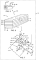
- a plate, board or tile 20 comprises an underside 22, an upper side 23, a first end or side 26, a second end or side 27, a third end or side 28 and a fourth end or side 29, see figs. 1 , 2 , 7 , 8A and 8B .
- These plate ends or sides 26, 27, 28 and 29 could be arranged pairwise opposite each other as the underside 22 and upper side 23 depending on the shape/preforming of the plate 20.
- These plate ends or sides 26, 27, 28 and 29 could be arranged pairwise at an angle between each other, such as 90° (perpendicular to each other) or at any angle less or larger than that depending on the final preformed desired shape of the plate 20.
- These plate ends or sides 26, 27, 28 and 29 could be pairwise arranged and extending in planes being in parallel with each other or angled in relation to each other depending on the final preformed shape of the plate 20.
- the underside 22 is adapted to be laid against the upper surface of the wet room 1.
- the upper side 23 is adapted to form a top layer of the wet room 1 when finished.
- the top layer/upper side 23 after being finished is plane, partly plane and/or partly sloping or sloping over its whole surface.
- the top layer/upper side 23 after being finished at least partly sloping or with a slope over its whole surface could have one sloping/rake at/on one part of its surface and another sloping/rake at/on another part of its surface. These varying slopes/rakes could be inclined in the same or similar directions or even opposite directions depending on the demands to fulfil regarding wet room standards/regulations.
- Each of the plate or board or tile ends or sides 26, 27, 28, 29 is adapted to be laid against or adjacent ends 26, 27, 28, 29 of other plates, boards or tiles 20 or a wall or the like in the wet room 1.
- the inventive system 10 and method not only enables making uneven floors even/plan/flat but also enables making the floor of a room into an approved wet room by evening out the inner room surface after laying out the plates 20 while at the same time establishing a correct sloping on the finished floor for water drainage and outflow, both partly and/or over the whole inner room surface 2 made up of the upper side 23 of each plate 20.
- the system 10 comprises points of reference 3 to be laid out or which are laid out on the inner wet room surface 2.
- each inner room and its inner room surface is unique in regard of measures/dimensions, slopes/inclinations/gradients, flatness, warping, levels, positions or placements of gullies and/or sinks, drains/drainage, flowing/sewer 4, or holes/openings 24 as parts of the floor and/or walls and/or ceiling of the room 1, and the actual inner room 1 and inner room surface 2 are scanned each time by a 3D scanner 30.
- This scanner and scanning 30 is adapted to scan the inner room surface 2 being at least part of the floor, walls and/or ceiling of the room 1 and the reference points 3 into a plurality of points of measuring 31.
- Scan 30 is done to create a digital 3D map representation 32, 33, 34, 35 of the inner room surface part 2 to be covered including its measures/dimensions, slopes, levels, inclinations/gradients, flatness, warping, positions or placements of at least one gully or sink, drain or drainage, flowing or sewer, water inlets and/or outlets 4 or the like being common entities in rooms, at least in a bathroom 1.
- the inner surface 2 could be part of a stair case and/or stairs to be covered with such pre-fabricated plates, boards and/or tiles 20.
- the inner surface 2 could be other parts, such as thresholds, i.e.
- the invention is combinable with use of a small, portable CNC machine for manufacturing or specially manufacture building parts on site, e.g. to cut out and/or sealingly fit thereby specially made surface coverage, i.e. at least parts of tiles, boards made of wood, stone and/or textile where required.
- each plate 20 must be adapted both on its underside 22 (into a schematically shown shape or profile in solid lines of fig. 8B ) and on its upper side 23 to fulfil the sloping criteria for at least a part and/or the whole room surface 2 in regard of wet room standards/approval.
- the inventor has invented a system 10, 11, 12, 13, 14 and a method to adapt and pre-fabricate coverage material into "tailor-made" underlay material of relevant plate material 20 being divided into, for the inner surface part 2, relevant geometrical parts that subsequently, during installation in the room 1, are distributed in a predefined order over the inner surface.
- Each plate 20 is prefabricated by forming/shaping at least its underside 22 and/or upper side 23 or both these sides or more of its sides to adapt the shape and dimension of each individual plate to the specific inner surface 2 and the 3D space required in the wet room 1.
- one or more plates 20 is prefabricated by forming/shaping at least its underside 22 and one or more of its ends or sides 26, 27, 28 and/or 29. In other areas of the wet room, one or more plates 20 is prefabricated by forming/shaping at least its underside 22 and its upper side 23. In yet other areas of the wet room 1, one or more plates 20 is prefabricated by forming/shaping at least its underside 22 and its upper side 23 and/or one or more of its ends or sides 26, 27, 28 and/or 29.
- a minority or majority/most of the plurality of the plates 20 making up the wet room 1 is prefabricated by forming/shaping at least their undersides 22 and their upper sides 23 and/or one or more of their ends/sides 26, 27, 28, 29. All plates 20 making up the wet room 1 is prefabricated by forming/shaping at least their undersides 22 and/or their upper sides 23 and/or one or more of their ends/sides 26, 27, 28, 29.
- the inventive pre-fabrication process is divided into several partial processes.
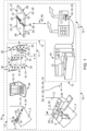
- a first process concerns scanning 30 the inner surface 2 for the creation of a CAD drawing being unique for the inner surface 2 and room 1, which is used to control the pre-manufacturing of the plates 20, see the three left upper views in Fig.
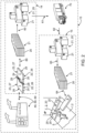
- a second process concerns applying the CAD drawing into a relevant CAM processing scheme to be used by appropriate manufacturing equipment 40 to control and perform manufacturing of each actual plate 20, see the top right view and the two lower right views of Fig. 1 visualized in box 12, and the two upper left views in Fig. 2 .
- a third process 11 concerns marking each pre-fabricated and finished plate 20 and packing them in a correct order in one or more packages 21 and/or set of packages 25, see the three upper right views visualized in box 14 and/or all the four upper views in Fig. 2 (in this process a unique installation instruction is also compiled and enclosed in the package 21).
- a fourth process 12 concerns unpacking each pre-fabricated and finished plate 20 in correct order from the packages 21, see the three lower left views of Fig. 2 and Figs. 5, 6, and 7 visualized in box 15 (in this process the unique installation instruction is used to correctly install the plates 20 in the room 1 and on the inner surface 2 in the correct pre-defined pattern).
- the processes of boxes 14 and 15 in combination with the transport 70 are visualized in a box 13 of Fig. 2 .
- the scanner 30 is a portable 3D scanner that could be handheld by an operator 5 or user or installer of pre-fabricated plates 20 during scanning.
- the scanner 30 is laser equipment and/or one or more cameras configured for 3D scanning of surfaces/volumes
- the room 1 has a door 6 and if the room is a bathroom it usually comprises at least one washbasin 7, toilet 8 and/or shower or shower bath and/or bathtub 9.
- the room is prepared, e.g. by cleaning, for installation of surface coverage including material for foundation or bedding or underlay or subfloor.
- one or more digital cameras 30 is/are used for creating one or more 3D models of the surface 2 by photogrammetry, whereby one or more "clouds of measuring points" is/are created by means of at least two or a plurality of digital images, enabling to read/scan the surface 2 in a corresponding way as the 3D scanner.
- structured light 3D scanners or "white light” 3D scanners most structured light 3D scanners using a blue or white LED projected light is usable. These 3D scanners project a light pattern consisting of bars, blocks or other shapes onto an object.
- the 3D scanner has one or more sensors that look at the edge of those patterns or structure shapes to determine the objects 3D shape of the surface 2.
- the distance from the sensors to the light source is known whereby one or more "clouds of measuring points" is/are achievable accordingly as for the techniques above.
- Structured light scanners can be tripod mounted or hand held
- the inner surface 2 of the room 1 to be covered by the pre-fabricated material in form of plates or boards and/or tiles 20 are scanned by the portable scanning equipment 30. Before doing this the inner surface 2 to be covered has been provided with required reference points 3 and horizontal lines and/or vertical lines, e.g. a digital water/spirit level with known length can be used.
- a design of a digital manufacturing scheme or programme for pre-shaping/pre-manufacturing these plates is performed by usage of the scanned data in the scanner 30.
- This data is forwarded to a CAD/CAM system 40 after scanning, e.g. a suitably equipped PC.
- CAD/CAM system 40 after scanning, e.g. a suitably equipped PC.
- the adaptation to any drainage, water inlet/outlet 4 on the inner surface 2, any shower walls or compartment in the room 1 and any levelling in relation to adjacent space/-s could be put into the digital manufacturing scheme or programme manually together with choice of cover material, i.e. type of plates 20.
- the inner surface 2 being scanned into a 3D representation 32 is divided into a suitable number of digital pieces 34 of a digital grid pattern 33, similar to a digital puzzle, and into digital representations 35 of each of the plates 20 in 3D to be physically manufactured accordingly.
- the plates 20 are suitably identified, e.g. by individual number markings, both digitally and physically to be easy to install according to the predefined grid pattern 33 at the final site, i.e. the actual room 1.
- One possible pattern is to layout the first plate 20 or 1 or 1 'to the furthest left as seen from a door 6 and then laying out subsequent plates 20 or 2 or 3 or X from/to the right of the first plate 20/ 1 / 1 '.
- Figure 1 shows the scanning by scanner 30 into data forwarded to the CAD/CAM system 40 receiving the points of measuring 31 from the 3D scanner 30.
- Figure 1 shows the CAD/CAM system 40 creating the digital 3D representation 32 of the part of the inner room surface 2 based on the points of measuring and transforming the digital 3D representation 32 into the grid pattern 33 with a suitable number of the individual digital plates 34 with unique identification and dimensions and a CAM controlling manufacturing workflow to manufacture each individual plate 20 accordingly.
- at least one CAD/CAM controlled machine 50 is shown receiving the CAM controlling manufacturing workflow and physically manufacturing and marking the plates 20 individually as unique entities accordingly.
- Figure 1 also shows the lay- out and installation of each individually pre-fabricated plate 20 on the inner surface 2 in the room 1 according to the predefined digital 3D representation 32, 33, 34, 35.
- the inner surface 2 is a floor but could of course be part of the walls and/or ceilings or a combination.
- the individual markings of the plates 20 with numerals being underlined such as 1 , 1' , 2 , 3 , 4 , 5 , 6 , 7 , 8 , 9 , 10 , 11 , 12 , 13 , and X in Figs. 1 , 2 , 4 , 6 , 7 , 8A , 8B , and 9 are used to denote each individual plate 20 so that each plate is individually formed/manufactured and packed correctly in a correct order before being transported to the room, and in a correct package 21, and laid out at its correct position in the room/space/part 1, 2 and plates that are intended to together make-up for example a sewer, i.e. an opening for it is denoted as a pair with numerals 1 and 1' , and may be identical or have different dimensions and/or shapes.
- the methods of pre-fabrication/pre-manufacturing of the plates 20 could be subtractive and/or additive manufacture, such as cutting, milling, turning, e.g. wood peeling, casting or moulding, e.g. of plastic or composite or stone or ceramic tiles, 3D printing, or lamination of plates in one or more steps or any method being a combination of one or more of the above.
- Figure 1 shows the inventive system 10 and method in full while Figures 2 , 5, 6, and 7 show the practical handling of the pre-fabricated plates 20 in more detail, i.e. concerning packaging 60 the plates 20 into one or more packages 21, loading 61 the packages 21 onto a transport 70, e.g. a truck/lorry or fork lift truck, unloading 62 one or more plate packages 21 from the transport 70 and moving 63 one or more of the plate packages 21 to the installation site, e.g. just outside the room 1, and finally unpacking 64 the plate packages 21 for final installation of individual plates 20 on the inner surface 2 of the room 1.
- a transport 70 e.g. a truck/lorry or fork lift truck
- the designer could add additional information into the digital manufacturing scheme or programme, e.g. apartment or room number, address of delivery, any marking or identification of their own, such as order number, or the like.
- This additional information enables providing basis for invoicing, packing and transport.
- the pre-shaping and pre-dimensioning of the plates 20 depends on if the inner surface 2 is flat or not, i.e. if it comprises sloping or not, and also if other ends or sides 26-29 of the plates 20 are to be adapted besides their undersides 22 and/or upper sides 23, then up to six plate sides could be adapted, e.g. if the plate is parallelepipedic.
- edges 26-29 of the plates 20 will be manufactured so that the plate comprises some type of tongue and groove jointing.
- Cellular or expanded plastic could be moulded or machined to smooth the underlay onto which the plates 20 are to be laid and then laying the plates as an additional layer, such as fiberboards 20 with a surface layer. The weight of the laid layer is then reduced and the pressure or load on for example an older or existing joist frame or wood joist ceiling is thereby educed.
- This construction may be laid as a floating floor without gluing if the floor is to be covered with parquet, laminate or other board materials.
- the invention enables pre-fabricating underlay, sealing or waterproof compound and surface coverage (for a wet room, i.e. a bathroom 1) in one and the same plate or module 20 meaning that the installation is made more effective and a uniform quality is able to be maintained/achieved. In that case, any joints between the plates or modules 20 are sealed/spliced. In such modules 20, integration of underfloor heating is possible.
- the invention enables performing so many steps as possible in one operation or process to eliminate as many manual steps as possible and at the same time increase the quality of the work and final resulting surface coverage.
- each plate 20 could be formed at least partly non-solid, e.g. by machining the underside 22 so that the plate weighs less or underfloor heating is able to be fitted to it. Hence, no additional adaptation of any plate 20 is required "in-situ”.
- the system 10 and method according to the invention are used for coverage of at least a part of the inner room surface 2 by means of a plurality of pre-fabricated and laid out plates 20.
- the system 10 and method comprises laid out/laying out of the points of reference 3 on the inner room surface 2, and scanning by means of the 3D scanner 30 the part of the inner room surface 2 and the points of reference 3 into the plurality of points of measuring 31 enabling creating the digital 3D representation 32, 33, 34, 35 of the inner room surface 2.
- the inventive system 10 and method uses the CAD/CAM system 40 configured to receive the points of measuring 31 from the 3D scanner 30 and to create the digital 3D representation 32, 33, 34, 35 of the inner room surface part 2 based on the measuring points and to transform the digital 3D representation into the suitable number of individual digital plates 34 with identification and dimensions and the CAM controlling manufacturing workflow to manufacture each individual plate 20 accordingly.
- the inventive system 10 and method use the at least one CAD/CAM controlled machine 50 configured to receive the CAM controlling manufacturing workflow and physically manufacture and mark the plates 20 individually accordingly. Then the layout of each individually pre-fabricated plate 20 in the room 1 is performed according to the predefined digital 3D representation 32, 33, 34, 35.
- the transformation of the digital 3D representation 32 of the inner room surface 2 by means of the CAD/CAM system 40 comprises dividing the digital 3D representation of the inner room surface into the digital grid pattern 33 with the suitable number of individual digital pieces 34, 35 corresponding to the individual plates 20 making up the inner room surface and identifying and dimensioning each individual plate digitally to enable the pre-fabrication of each individual plate physically by means of the CAM controlling manufacturing workflow before laying-out the individual plates after manufacture according to the predefined grid pattern in the room 1.
- the CAM controlling manufacturing workflow is adapted to control the at least one CAD/CAM controlled machine 50 for manufacturing each plate 20 individually on at least one side 22, 23.
- the CAM controlling manufacturing workflow is adapted to control the at least one CAD/CAM controlled machine 50 when manufacturing each plate 20 individually on at least either the underside 22 and/or upper side 23 to preform the plate to fit the exposed or upper/top or lower inner wet room surface 2 when it is laid thereon with its underside.
- the CAM controlling manufacturing work-flow controls the at least one CAD/CAM controlled machine 50 to manufacture each plate 20 individually on an underside 22 and an upper side 23 to preform the plate to fit the exposed or upper or lower room surface 2 onto which it is to be laid with its underside 22 and to fit its upper side 23 into any predefined slope of the finished inner room surface to enable drainage 4 or outflow of water or the like or for compensating for bulging walls or ceilings of room 1.
- the CAM controlling manufacturing workflow is adapted to control the at least one CAD/CAM controlled machine 50 when manufacturing each plate 20 individually to accomplish any predefined slopes of the finished inner room surface 2 and making any opening 4, 24 through one or more associated plates as lead-through for any drain and/or water inlet or gully drain in room 1 if required according to the digital 3D representation of the inner room surface.
- An additional aspect of the system 10 comprises at least one process of packing 60 adapted to pack the pre-fabricated plates 20 in a pre-defined order according to the individual marking of each plate into at least one package 21 or two or more packages into a set 25 of plate packages before layout of each individual plate of each package 21 in the room 1 according to the pre-defined digital 3D representation 32, 33, 34.
- System 10 in another aspect comprises at least the transport 70 to deliver the at least one plate package 21 at room 1 before layout of each individual plate in the room according to the predefined digital 3D representation 32, 33, 34.
- the method according to the invention concerns pre-fabricating and laying out plates 20 for coverage of at least a part of the inner room surface 2 and comprises laying out the points of reference 3 on the inner room surface 2 and performing the 3D scanning 30 of the part of the inner room surface 2 and the points of reference 3 into the plurality of points of measuring 31.
- the method according to the invention further comprises sending the plurality of points of measuring 31 as data from the 3D scanning to the CAD/CAM system 40 and creating the digital 3D representation 32, 33, 34, 35 of the inner room surface 2 based on the data of the received points of measuring 31 from the 3D scanning 30 by means of the CAD/CAM system 40 and transforming the digital 3D representation 32 into the suitable number of individual digital plates 34, 35 with unique identification and dimensions and the digital CAM controlling manufacturing workflow for physically manufacturing each individual plate 20 accordingly for pre-fabrication and sending the digital CAM controlling manufacturing workflow to the at least one CAD/CAM controlled machine 50 for manufacturing and marking the physical plates 20 individually accordingly, and laying out each individually pre-fabricated plate 20 in the room 1 according to the predefined digital 3D representation 32, 33, 34.
- Aspects of the inventive method perform corresponding steps as above for the inventive system 10.
Landscapes
- Engineering & Computer Science (AREA)
- Architecture (AREA)
- Physics & Mathematics (AREA)
- General Physics & Mathematics (AREA)
- Structural Engineering (AREA)
- Civil Engineering (AREA)
- Geometry (AREA)
- Human Computer Interaction (AREA)
- Manufacturing & Machinery (AREA)
- Automation & Control Theory (AREA)
- Theoretical Computer Science (AREA)
- Chemical & Material Sciences (AREA)
- Ceramic Engineering (AREA)
- Computational Mathematics (AREA)
- Computer Hardware Design (AREA)
- Pure & Applied Mathematics (AREA)
- Mathematical Optimization (AREA)
- Mathematical Analysis (AREA)
- Evolutionary Computation (AREA)
- General Engineering & Computer Science (AREA)
- Finishing Walls (AREA)
- Making Paper Articles (AREA)
- Manufacturing Of Printed Wiring (AREA)
- Road Signs Or Road Markings (AREA)
- Installation Of Indoor Wiring (AREA)
- Treatments For Attaching Organic Compounds To Fibrous Goods (AREA)
- Chemical And Physical Treatments For Wood And The Like (AREA)
Claims (10)
- System (10) zur Abdeckung mindestens eines Teils einer Innenfläche (2) eines Nassraums (1) mittels einer Vielzahl von vorgefertigten und verlegten Platten (20), das System (10) umfassend verlegte Referenzpunkte (3) auf der Innennassraumfläche (2),einen 3D-Scanner (30), der dazu ausgelegt ist, den Teil der Innennassraumfläche (2) und die Referenzpunkte (3) in eine Vielzahl von Messpunkten (31) zu scannen, um das Erzeugen einer digitalen 3D-Darstellung (32, 33, 34, 35) des Teils der Innennassraumfläche (2) zu ermöglichen,ein CAD/CAM-System (40), das dazu ausgelegt ist, die Messpunkte (31) von dem 3D-Scanner (30) zu empfangen und die digitale 3D-Darstellung (32, 33, 34, 35) des Teils der Innennassraumfläche (2) basierend auf den Messpunkten zu erzeugen und die digitale 3D-Darstellung in eine geeignete Anzahl einzelner digitaler Platen (34) mit Identifizierung und Abmessungen und einem Cam-Steuerungs-Herstellungsarbeitsablauf umzuwandeln, um jede einzelne Platte (20) entsprechend herzustellen,mindestens eine CAD/CAM-gesteuerte Maschine (50), die dazu ausgelegt ist, den CAM-Steuerungs-Herstellungsarbeitsablauf zu empfangen und die Platten (20) entsprechend einzeln physisch herzustellen, undein Verlegen jeder einzeln vorgefertigten Platte (20) im Nassraum (1) gemäß der vorgegebenen digitalen 3D-Darstellung (32, 33, 34, 35),dadurch gekennzeichnet, dass der CAM-Steuerungs-Herstellungsarbeitsablauf abgestimmt ist, um die mindestens eine CAD/CAM-gesteuerte Maschine (50) zu steuern, wenn jede Platte (20) einzeln mindestens auf ihrer Unterseite (22) und ihrer Oberseite (23) hergestellt wird, um die Platte vorzuformen, um auf die Oberfläche der Innenraumfläche (2) des Nassraums (1) zu passen, auf die sie mit ihrer Unterseite zu legen ist, und um die Platte vorzuformen, um auf ihre Oberseite in jegliche vorgegebene Neigung der endgültigen Innennassraumfläche zu passen, wenn sie fertiggestellt ist, um ein Ablassen (4) oder Ausströmen von Wasser oder dergleichen zu ermöglichen.
- System (10) nach Anspruch 1, wobei die mindestens eine CAD/CAM-gesteuerte Maschine (50) dazu ausgelegt ist, die Platten (20) entsprechend physisch herzustellen und einzeln zu markieren, und das Umwandeln der digitalen 3D-Darstellung (32) der Innenraumfläche (2) mittels des CAD/CAM-Systems (40) das Unterteilen der digitalen 3D-Darstellung der Innenraumfläche in ein digitales Rastermuster (33) mit einer geeigneten Anzahl von einzelnen digitalen Stücken (34, 35), die den einzelnen Platten (20) entsprechen, die die Innenraumfläche bilden, und das Identifizieren sowie Abmessen jeder einzelnen Platte digital umfasst, um ein physisches Vorfertigen jeder einzelnen Platte mittels des CAM-Steuerungs-Herstellungsarbeitsablaufs vor dem Verlegen der einzelnen Platten nach der Herstellung gemäß dem vorgegebenen Rastermuster in dem Nassraum (1) zu ermöglichen.
- System (10) nach Anspruch 1 oder 2, wobei der CAM-Steuerungs-Arbeitsablauf abgestimmt ist, um die mindestens eine CAD/CAM-gesteuerte Maschine (50) zu steuern, wenn jede Platte ( 20 ) einzeln hergestellt wird, um jegliche vorgegebenen Neigungen der fertiggestellten Innenraumfläche (2) zu erzielen, und um jegliche Öffnung (4, 24) durch eine oder mehrere zugehörige Platten als Durchführung für jeglichen Abfluss und/oder Wassereinlass oder Abwasserabfluss in dem Nassraum (1) zu erstellen, falls erforderlich gemäß der digitalen 3D-Darstellung der Innenraumfläche.
- System (10) nach einem der vorhergehenden Ansprüche, umfassend mindestens eine Packung (60), die ausgestaltet ist, um die vorgefertigten Platten (20) in einer vorgegebenen Reihenfolge gemäß der einzelnen Markierung jeder Platte in mindestens ein Paket (21, 25) von Platten vor dem Verlegen jeder einzelnen Platte des Pakets (21) in dem Nassraum (1) gemäß der vorgegebenen digitalen 3D-Darstellung (32, 33, 34) zu verpacken.
- System (10) nach Anspruch 4, umfassend mindestens einen Transport (70) zum Abgeben des mindestens einen Plattenpakets (21) am Raum (1) vor dem Verlegen jeder einzelnen Platte (20) im Raum gemäß der vorgegebenen digitalen 3D-Darstellung (32, 33, 34).
- Verfahren zum Vorfertigen und Verlegen von Platten (20) zur Abdeckung zumindest eines Teils einer Innenfläche (2) eines Nassraums (1), umfassend das Verlegen von Referenzpunkten (3) auf der Innenraumfläche (2),3D-Scannen (30) des Teils der Innenraumfläche (2) und der Referenzpunkte (3) in eine Vielzahl von Messpunkten (31),Senden der Vielzahl von Messpunkten (31) von dem 3D-Scannen an ein CAD/CAM-System (40),Erzeugen einer digitalen 3D-Darstellung (32, 33, 34, 35) der Innenraumfläche (2) basierend auf den empfangenen Messpunkten (31) von dem 3D-Scannen (30) mittels des CAD/CAM-Systems (40),Umwandeln der digitalen 3D-Darstellung (32) in eine geeignete Anzahl einzelner digitaler Platten (34, 35) mit Identifizierung und Abmessungen und einem digitalen CAM-Steuerungs-Herstellungsarbeitsablauf, um jede einzelne Platte (20) entsprechend für die Vorfertigung physisch herzustellen,Senden des digitalen Cam-Steuerungs- Herstellungsarbeitsablaufs an mindestens eine CAD/CAM-gesteuerte Maschine (50), um die physischen Platten (20) entsprechend einzeln herzustellen, undVerlegen jeder einzeln vorgefertigten Platte (20) im Raum (1) gemäß der vorgegebenen digitalen 3D-Darstellung (32, 33, 34),gekennzeichnet durchden CAM-Steuerungs-Herstellungsarbeitsablauf umfassend, dass jede Platte (20) einzeln mindestens auf ihrer Unterseite (22) und ihrer Oberseite (23) hergestellt wird, um die Platte vorzuformen, um auf die Oberfläche der Innenraumfläche (2) zu passen, auf die sie mit ihrer Unterseite zu legen ist, und um auf ihre Oberseite in jegliche vorgegebene Neigung der endgültigen Innenraumfläche zu passen, wenn sie fertiggestellt ist, um ein Ablassen (4, 24) oder Ausströmen von Wasser zu ermöglichen.
- Verfahren nach Anspruch 6, wobei der CAM-Steuerungs-Herstellungsarbeitsablauf jede Platte (20) einzeln bildet, um jegliche vorgegebenen Neigungen der fertiggestellten Innenraumfläche (2) zu erzielen, und jegliche Öffnung (24) durch eine oder mehrere zugehörige Platten erstellt, um die Durchführung für jeglichen Abfluss und/oder Wassereinlass (4) oder Abwasserabfluss in dem Nassraum (1) vorzuformen, falls erforderlich gemäß der digitalen 3D-Darstellung der Innenraumfläche, wenn die Innenraumfläche abgedeckt wird.
- Verfahren nach einem der Ansprüche 6 bis 7, umfassend die Packung (60) der vorgefertigten Platten (20) in einer vorgegebenen Reihenfolge gemäß der einzelnen Markierung jeder Platte in mindestens ein Paket (21) von Platten vor dem Verlegen jeder einzelnen Platte in dem Nassraum (1) gemäß der vorgegebenen digitalen 3D-Darstellung (32, 33, 34).
- Verfahren nach Anspruch 8, umfassend einen Transport (70) zum Abgeben mindestens eines Plattenpakets (21) am Raum (1) vor dem Verlegen jeder einzelnen Platte (20) in dem Nassraum (1) gemäß der vorgegebenen digitalen 3D-Darstellung (32, 33, 34).
- Verfahren nach Anspruch 9, wobei die mindestens eine CAD/CAM-gesteuerte Maschine (50) zum Herstellen die physischen Platten (20) einzeln entsprechend markiert und das Umwandeln der digitalen 3D-Darstellung (32) der Innenraumfläche (2) das Unterteilen der digitalen 3D-Darstellung in ein digitales Rastermuster (33) mit einer geeigneten Anzahl von einzelnen digitalen Stücken (34, 35), die den physischen einzelnen Platten (20) entsprechen, die die Innenraumfläche bilden, und das Identifizieren sowie Abmessen jedes einzelnen Stücks (34) digital umfasst, um ein physisches Vorfertigen jeder einzelnen Platte (20) mittels des CAM-Steuerungs-Herstellungsarbeitsablaufs vor dem physischen Verlegen der einzelnen Platten nach der Herstellung gemäß dem vorgegebenen Rastermuster (33) in dem Nassraum (1) zu ermöglichen.
Priority Applications (3)
| Application Number | Priority Date | Filing Date | Title |
|---|---|---|---|
| RS20230361A RS64193B1 (sr) | 2018-03-27 | 2019-03-27 | Sistem i metoda prefabrikovanja i polaganja pokrivke površine prostorije |
| HRP20230446TT HRP20230446T1 (hr) | 2018-03-27 | 2019-03-27 | Sustav i postupak predizrade i postavljanja pokrova površine prostorije |
| SI201930541T SI3775432T1 (sl) | 2018-03-27 | 2019-03-27 | Sistem in postopek predizdelave in polaganja obloge talne površine sobe |
Applications Claiming Priority (2)
| Application Number | Priority Date | Filing Date | Title |
|---|---|---|---|
| SE1850337 | 2018-03-27 | ||
| PCT/SE2019/050277 WO2019190386A1 (en) | 2018-03-27 | 2019-03-27 | System and method for pre-fabrication and laying out of coverage of a room surface |
Publications (2)
| Publication Number | Publication Date |
|---|---|
| EP3775432A1 EP3775432A1 (de) | 2021-02-17 |
| EP3775432B1 true EP3775432B1 (de) | 2023-02-22 |
Family
ID=66041621
Family Applications (1)
| Application Number | Title | Priority Date | Filing Date |
|---|---|---|---|
| EP19715594.8A Active EP3775432B1 (de) | 2018-03-27 | 2019-03-27 | System und verfahren zur vorfertigung und verlegung der abdeckung einer raumfläche |
Country Status (13)
| Country | Link |
|---|---|
| US (1) | US20210164237A1 (de) |
| EP (1) | EP3775432B1 (de) |
| DK (1) | DK3775432T3 (de) |
| ES (1) | ES2945207T3 (de) |
| FI (1) | FI3775432T3 (de) |
| HR (1) | HRP20230446T1 (de) |
| HU (1) | HUE061786T2 (de) |
| LT (1) | LT3775432T (de) |
| PL (1) | PL3775432T3 (de) |
| PT (1) | PT3775432T (de) |
| RS (1) | RS64193B1 (de) |
| SI (1) | SI3775432T1 (de) |
| WO (1) | WO2019190386A1 (de) |
Families Citing this family (3)
| Publication number | Priority date | Publication date | Assignee | Title |
|---|---|---|---|---|
| DE102020131249A1 (de) | 2020-11-25 | 2022-05-25 | Tilo Gmbh | Ausgleichselement |
| NL2028078B1 (en) * | 2021-04-27 | 2022-11-03 | Sip B V | Method for the designing and production of a renovation element for a staircase part |
| GB2640538A (en) * | 2024-04-23 | 2025-10-29 | Uh Ai Ltd | Boards for an underfloor heating system |
Family Cites Families (7)
| Publication number | Priority date | Publication date | Assignee | Title |
|---|---|---|---|---|
| GB2437370B (en) * | 2006-04-21 | 2010-07-14 | Brik Contracting Ltd | Sub-floor and method of constructing a sub-floor |
| DE102006052813A1 (de) * | 2006-11-09 | 2008-05-15 | Robert Bosch Gmbh | Mobiles Messsystem zur Erfassung von Raumprofilschnitten |
| PL2852717T3 (pl) * | 2012-05-16 | 2021-09-13 | Grade Group As | Układ do pokrywania powierzchni i sposób produkcji takiego układu |
| AU2013362817B2 (en) * | 2012-12-21 | 2018-03-08 | Lifting Point Pty Ltd | Plumbing drainage coupling member and associated method |
| DE102014011649A1 (de) * | 2014-08-11 | 2016-02-11 | Marco Deckelmann | Vorrichtung zum Auslegen eines vorbestimmten Bereichs und Verfahren zum Auslegen eines vorbestimmten Bereichs |
| JP7061119B2 (ja) * | 2016-07-15 | 2022-04-27 | ファストブリック・アイピー・プロプライエタリー・リミテッド | 車両に組み込まれた煉瓦/ブロック敷設機 |
| BE1024775B1 (nl) * | 2016-12-01 | 2018-07-02 | Unilin Bvba | Set van vloerpanelen en werkwijze voor het samenstellen ervan. |
-
2019
- 2019-03-27 WO PCT/SE2019/050277 patent/WO2019190386A1/en not_active Ceased
- 2019-03-27 FI FIEP19715594.8T patent/FI3775432T3/fi active
- 2019-03-27 DK DK19715594.8T patent/DK3775432T3/da active
- 2019-03-27 ES ES19715594T patent/ES2945207T3/es active Active
- 2019-03-27 EP EP19715594.8A patent/EP3775432B1/de active Active
- 2019-03-27 LT LTEPPCT/SE2019/050277T patent/LT3775432T/lt unknown
- 2019-03-27 HU HUE19715594A patent/HUE061786T2/hu unknown
- 2019-03-27 US US17/042,026 patent/US20210164237A1/en not_active Abandoned
- 2019-03-27 SI SI201930541T patent/SI3775432T1/sl unknown
- 2019-03-27 PL PL19715594.8T patent/PL3775432T3/pl unknown
- 2019-03-27 RS RS20230361A patent/RS64193B1/sr unknown
- 2019-03-27 PT PT197155948T patent/PT3775432T/pt unknown
- 2019-03-27 HR HRP20230446TT patent/HRP20230446T1/hr unknown
Also Published As
| Publication number | Publication date |
|---|---|
| ES2945207T3 (es) | 2023-06-29 |
| HUE061786T2 (hu) | 2023-08-28 |
| US20210164237A1 (en) | 2021-06-03 |
| DK3775432T3 (da) | 2023-05-22 |
| PL3775432T3 (pl) | 2023-06-12 |
| WO2019190386A1 (en) | 2019-10-03 |
| PT3775432T (pt) | 2023-05-24 |
| LT3775432T (lt) | 2023-06-12 |
| EP3775432A1 (de) | 2021-02-17 |
| FI3775432T3 (fi) | 2023-05-22 |
| RS64193B1 (sr) | 2023-06-30 |
| SI3775432T1 (sl) | 2023-09-29 |
| HRP20230446T1 (hr) | 2023-07-07 |
Similar Documents
| Publication | Publication Date | Title |
|---|---|---|
| EP3775432B1 (de) | System und verfahren zur vorfertigung und verlegung der abdeckung einer raumfläche | |
| CN104541004B (zh) | 表面覆盖系统及用于制备这样的系统的方法 | |
| US7735277B1 (en) | Simulated brick building panel | |
| CN204163299U (zh) | 用于一体化室内集成装修组件 | |
| CN112101908A (zh) | 一种全预制无损拆装的装配式装修施工方法 | |
| CN115822305B (zh) | 仿古建筑外墙艺术饰面施工工法 | |
| CN105464309A (zh) | 一体化室内集成装修方法及其装修组件 | |
| EP2405062A1 (de) | Duschablauf mit Einsatz | |
| US20200340255A1 (en) | Flooring system, a panel and methods of use thereof | |
| US20180355609A1 (en) | Permanent form panel, assembly of said panels, and method for producing a concrete floor slab | |
| US9408501B2 (en) | Shower stall curb cover | |
| CN114197857A (zh) | 一种彩色清水混凝土施工工艺体系 | |
| WO2026093515A1 (en) | Pre-fabrication and installation of coverage of an inner room surface | |
| CN112982913A (zh) | 一种基于物联网的瓷砖批量化加工精确排版定位施工工艺 | |
| US20200199889A1 (en) | Deck system and method of installing | |
| CN201050167Y (zh) | 带走线盖的硫酸钙活动地板 | |
| RU239085U1 (ru) | Модуль тёплого водяного чернового пола сухого монтажа | |
| CN206034855U (zh) | 一种新型的地面龙骨结构 | |
| AU2024200979A1 (en) | Floor Fall Panels and a Method for the Design Thereof | |
| CN219451497U (zh) | 一种木胶合板封闭式楼梯施工装置 | |
| SITE | occupation. | |
| WO2004055298A2 (en) | Procedure for the construction of building works by using prefabricated wall-elements and prefabricated basic and other wall-elements | |
| DK178315B8 (en) | Base Rendering | |
| Loh et al. | HOUSE# 05 Incremental Construction in Digital Practice | |
| CN120706081A (zh) | 一种砖材的数字化建模方法及其信息处理系统 |
Legal Events
| Date | Code | Title | Description |
|---|---|---|---|
| REG | Reference to a national code |
Ref country code: HR Ref legal event code: TUEP Ref document number: P20230446T Country of ref document: HR |
|
| STAA | Information on the status of an ep patent application or granted ep patent |
Free format text: STATUS: UNKNOWN |
|
| STAA | Information on the status of an ep patent application or granted ep patent |
Free format text: STATUS: THE INTERNATIONAL PUBLICATION HAS BEEN MADE |
|
| PUAI | Public reference made under article 153(3) epc to a published international application that has entered the european phase |
Free format text: ORIGINAL CODE: 0009012 |
|
| STAA | Information on the status of an ep patent application or granted ep patent |
Free format text: STATUS: REQUEST FOR EXAMINATION WAS MADE |
|
| 17P | Request for examination filed |
Effective date: 20201022 |
|
| AK | Designated contracting states |
Kind code of ref document: A1 Designated state(s): AL AT BE BG CH CY CZ DE DK EE ES FI FR GB GR HR HU IE IS IT LI LT LU LV MC MK MT NL NO PL PT RO RS SE SI SK SM TR |
|
| AX | Request for extension of the european patent |
Extension state: BA ME |
|
| DAV | Request for validation of the european patent (deleted) | ||
| DAX | Request for extension of the european patent (deleted) | ||
| GRAP | Despatch of communication of intention to grant a patent |
Free format text: ORIGINAL CODE: EPIDOSNIGR1 |
|
| STAA | Information on the status of an ep patent application or granted ep patent |
Free format text: STATUS: GRANT OF PATENT IS INTENDED |
|
| INTG | Intention to grant announced |
Effective date: 20220912 |
|
| GRAS | Grant fee paid |
Free format text: ORIGINAL CODE: EPIDOSNIGR3 |
|
| GRAA | (expected) grant |
Free format text: ORIGINAL CODE: 0009210 |
|
| STAA | Information on the status of an ep patent application or granted ep patent |
Free format text: STATUS: THE PATENT HAS BEEN GRANTED |
|
| AK | Designated contracting states |
Kind code of ref document: B1 Designated state(s): AL AT BE BG CH CY CZ DE DK EE ES FI FR GB GR HR HU IE IS IT LI LT LU LV MC MK MT NL NO PL PT RO RS SE SI SK SM TR |
|
| RAP3 | Party data changed (applicant data changed or rights of an application transferred) |
Owner name: STIBE MODUL AB |
|
| REG | Reference to a national code |
Ref country code: GB Ref legal event code: FG4D Ref country code: TN Ref legal event code: VAGR Ref document number: TN/P/2023/000103 Country of ref document: TN |
|
| REG | Reference to a national code |
Ref country code: CH Ref legal event code: EP |
|
| REG | Reference to a national code |
Ref country code: AT Ref legal event code: REF Ref document number: 1549615 Country of ref document: AT Kind code of ref document: T Effective date: 20230315 Ref country code: IE Ref legal event code: FG4D |
|
| REG | Reference to a national code |
Ref country code: DE Ref legal event code: R096 Ref document number: 602019025522 Country of ref document: DE |
|
| REG | Reference to a national code |
Ref country code: DK Ref legal event code: T3 Effective date: 20230516 |
|
| REG | Reference to a national code |
Ref country code: PT Ref legal event code: SC4A Ref document number: 3775432 Country of ref document: PT Date of ref document: 20230524 Kind code of ref document: T Free format text: AVAILABILITY OF NATIONAL TRANSLATION Effective date: 20230518 |
|
| REG | Reference to a national code |
Ref country code: NL Ref legal event code: FP |
|
| REG | Reference to a national code |
Ref country code: SE Ref legal event code: TRGR |
|
| P01 | Opt-out of the competence of the unified patent court (upc) registered |
Effective date: 20230509 |
|
| REG | Reference to a national code |
Ref country code: NO Ref legal event code: T2 Effective date: 20230222 |
|
| REG | Reference to a national code |
Ref country code: ES Ref legal event code: FG2A Ref document number: 2945207 Country of ref document: ES Kind code of ref document: T3 Effective date: 20230629 |
|
| REG | Reference to a national code |
Ref country code: HR Ref legal event code: T1PR Ref document number: P20230446 Country of ref document: HR Ref country code: HR Ref legal event code: ODRP Ref document number: P20230446 Country of ref document: HR Payment date: 20230621 Year of fee payment: 5 |
|
| REG | Reference to a national code |
Ref country code: SK Ref legal event code: T3 Ref document number: E 41630 Country of ref document: SK |
|
| REG | Reference to a national code |
Ref country code: EE Ref legal event code: FG4A Ref document number: E023351 Country of ref document: EE Effective date: 20230517 |
|
| REG | Reference to a national code |
Ref country code: GR Ref legal event code: EP Ref document number: 20230400713 Country of ref document: GR Effective date: 20230613 |
|
| REG | Reference to a national code |
Ref country code: HU Ref legal event code: AG4A Ref document number: E061786 Country of ref document: HU |
|
| PG25 | Lapsed in a contracting state [announced via postgrant information from national office to epo] |
Ref country code: SM Free format text: LAPSE BECAUSE OF FAILURE TO SUBMIT A TRANSLATION OF THE DESCRIPTION OR TO PAY THE FEE WITHIN THE PRESCRIBED TIME-LIMIT Effective date: 20230222 |
|
| REG | Reference to a national code |
Ref country code: DE Ref legal event code: R097 Ref document number: 602019025522 Country of ref document: DE |
|
| PG25 | Lapsed in a contracting state [announced via postgrant information from national office to epo] |
Ref country code: AL Free format text: LAPSE BECAUSE OF FAILURE TO SUBMIT A TRANSLATION OF THE DESCRIPTION OR TO PAY THE FEE WITHIN THE PRESCRIBED TIME-LIMIT Effective date: 20230222 |
|
| PLBE | No opposition filed within time limit |
Free format text: ORIGINAL CODE: 0009261 |
|
| STAA | Information on the status of an ep patent application or granted ep patent |
Free format text: STATUS: NO OPPOSITION FILED WITHIN TIME LIMIT |
|
| 26N | No opposition filed |
Effective date: 20231123 |
|
| REG | Reference to a national code |
Ref country code: HR Ref legal event code: ODRP Ref document number: P20230446 Country of ref document: HR Payment date: 20240313 Year of fee payment: 6 |
|
| REG | Reference to a national code |
Ref country code: HR Ref legal event code: ODRP Ref document number: P20230446 Country of ref document: HR Payment date: 20250127 Year of fee payment: 7 |
|
| PGFP | Annual fee paid to national office [announced via postgrant information from national office to epo] |
Ref country code: BG Payment date: 20250121 Year of fee payment: 7 |
|
| PGFP | Annual fee paid to national office [announced via postgrant information from national office to epo] |
Ref country code: HU Payment date: 20250124 Year of fee payment: 7 |
|
| PGFP | Annual fee paid to national office [announced via postgrant information from national office to epo] |
Ref country code: SI Payment date: 20250129 Year of fee payment: 7 |
|
| PGFP | Annual fee paid to national office [announced via postgrant information from national office to epo] |
Ref country code: ES Payment date: 20250523 Year of fee payment: 7 |
|
| PGFP | Annual fee paid to national office [announced via postgrant information from national office to epo] |
Ref country code: CH Payment date: 20250401 Year of fee payment: 7 |
|
| PG25 | Lapsed in a contracting state [announced via postgrant information from national office to epo] |
Ref country code: CY Free format text: LAPSE BECAUSE OF FAILURE TO SUBMIT A TRANSLATION OF THE DESCRIPTION OR TO PAY THE FEE WITHIN THE PRESCRIBED TIME-LIMIT; INVALID AB INITIO Effective date: 20190327 |
|
| REG | Reference to a national code |
Ref country code: AT Ref legal event code: UEP Ref document number: 1549615 Country of ref document: AT Kind code of ref document: T Effective date: 20230222 |
|
| PGFP | Annual fee paid to national office [announced via postgrant information from national office to epo] |
Ref country code: FI Payment date: 20251223 Year of fee payment: 8 |
|
| PGFP | Annual fee paid to national office [announced via postgrant information from national office to epo] |
Ref country code: NL Payment date: 20260123 Year of fee payment: 8 |
|
| REG | Reference to a national code |
Ref country code: CH Ref legal event code: U11 Free format text: ST27 STATUS EVENT CODE: U-0-0-U10-U11 (AS PROVIDED BY THE NATIONAL OFFICE) Effective date: 20260401 |
|
| PGFP | Annual fee paid to national office [announced via postgrant information from national office to epo] |
Ref country code: SE Payment date: 20260119 Year of fee payment: 8 |
|
| PGFP | Annual fee paid to national office [announced via postgrant information from national office to epo] |
Ref country code: LT Payment date: 20260127 Year of fee payment: 8 Ref country code: GB Payment date: 20260119 Year of fee payment: 8 |
|
| PGFP | Annual fee paid to national office [announced via postgrant information from national office to epo] |
Ref country code: MC Payment date: 20260202 Year of fee payment: 8 |
|
| REG | Reference to a national code |
Ref country code: HR Ref legal event code: ODRP Ref document number: P20230446 Country of ref document: HR Payment date: 20260210 Year of fee payment: 8 |
|
| PGFP | Annual fee paid to national office [announced via postgrant information from national office to epo] |
Ref country code: DE Payment date: 20260216 Year of fee payment: 8 Ref country code: NO Payment date: 20260227 Year of fee payment: 8 Ref country code: DK Payment date: 20260123 Year of fee payment: 8 Ref country code: IE Payment date: 20260226 Year of fee payment: 8 |
|
| PGFP | Annual fee paid to national office [announced via postgrant information from national office to epo] |
Ref country code: AT Payment date: 20260216 Year of fee payment: 8 Ref country code: HR Payment date: 20260210 Year of fee payment: 8 |
|
| PGFP | Annual fee paid to national office [announced via postgrant information from national office to epo] |
Ref country code: RO Payment date: 20260310 Year of fee payment: 8 Ref country code: LU Payment date: 20260306 Year of fee payment: 8 Ref country code: BE Payment date: 20260122 Year of fee payment: 8 Ref country code: IT Payment date: 20260218 Year of fee payment: 8 |
|
| PGFP | Annual fee paid to national office [announced via postgrant information from national office to epo] |
Ref country code: RS Payment date: 20260302 Year of fee payment: 8 |
|
| PGFP | Annual fee paid to national office [announced via postgrant information from national office to epo] |
Ref country code: IS Payment date: 20260320 Year of fee payment: 8 Ref country code: FR Payment date: 20260121 Year of fee payment: 8 |
|
| PGFP | Annual fee paid to national office [announced via postgrant information from national office to epo] |
Ref country code: TR Payment date: 20260206 Year of fee payment: 8 |
|
| PGFP | Annual fee paid to national office [announced via postgrant information from national office to epo] |
Ref country code: PT Payment date: 20260129 Year of fee payment: 8 Ref country code: CZ Payment date: 20260121 Year of fee payment: 8 |
|
| PGFP | Annual fee paid to national office [announced via postgrant information from national office to epo] |
Ref country code: GR Payment date: 20260226 Year of fee payment: 8 Ref country code: PL Payment date: 20260220 Year of fee payment: 8 |
|
| PGFP | Annual fee paid to national office [announced via postgrant information from national office to epo] |
Ref country code: EE Payment date: 20260209 Year of fee payment: 8 Ref country code: LV Payment date: 20260202 Year of fee payment: 8 Ref country code: SK Payment date: 20260209 Year of fee payment: 8 |