EP3774592B1 - Verteiler für ventil mit feststehendem ventilkörpergehäuse - Google Patents
Verteiler für ventil mit feststehendem ventilkörpergehäuse Download PDFInfo
- Publication number
- EP3774592B1 EP3774592B1 EP19719116.6A EP19719116A EP3774592B1 EP 3774592 B1 EP3774592 B1 EP 3774592B1 EP 19719116 A EP19719116 A EP 19719116A EP 3774592 B1 EP3774592 B1 EP 3774592B1
- Authority
- EP
- European Patent Office
- Prior art keywords
- straw
- sleeve
- flow channel
- dispenser
- bendable segment
- Prior art date
- Legal status (The legal status is an assumption and is not a legal conclusion. Google has not performed a legal analysis and makes no representation as to the accuracy of the status listed.)
- Active
Links
Images

Classifications
-
- B—PERFORMING OPERATIONS; TRANSPORTING
- B65—CONVEYING; PACKING; STORING; HANDLING THIN OR FILAMENTARY MATERIAL
- B65D—CONTAINERS FOR STORAGE OR TRANSPORT OF ARTICLES OR MATERIALS, e.g. BAGS, BARRELS, BOTTLES, BOXES, CANS, CARTONS, CRATES, DRUMS, JARS, TANKS, HOPPERS, FORWARDING CONTAINERS; ACCESSORIES, CLOSURES, OR FITTINGS THEREFOR; PACKAGING ELEMENTS; PACKAGES
- B65D83/00—Containers or packages with special means for dispensing contents
- B65D83/14—Containers for dispensing liquid or semi-liquid contents by internal gaseous pressure, i.e. aerosol containers comprising propellant
- B65D83/16—Actuating means
- B65D83/18—Hand lever actuators
-
- B—PERFORMING OPERATIONS; TRANSPORTING
- B65—CONVEYING; PACKING; STORING; HANDLING THIN OR FILAMENTARY MATERIAL
- B65D—CONTAINERS FOR STORAGE OR TRANSPORT OF ARTICLES OR MATERIALS, e.g. BAGS, BARRELS, BOTTLES, BOXES, CANS, CARTONS, CRATES, DRUMS, JARS, TANKS, HOPPERS, FORWARDING CONTAINERS; ACCESSORIES, CLOSURES, OR FITTINGS THEREFOR; PACKAGING ELEMENTS; PACKAGES
- B65D83/00—Containers or packages with special means for dispensing contents
- B65D83/14—Containers for dispensing liquid or semi-liquid contents by internal gaseous pressure, i.e. aerosol containers comprising propellant
- B65D83/28—Nozzles, nozzle fittings or accessories specially adapted therefor
- B65D83/30—Nozzles, nozzle fittings or accessories specially adapted therefor for guiding the flow of the dispensed content, e.g. funnels or hoods
- B65D83/306—Actuators formed as a rigid elongate spout
-
- B—PERFORMING OPERATIONS; TRANSPORTING
- B05—SPRAYING OR ATOMISING IN GENERAL; APPLYING FLUENT MATERIALS TO SURFACES, IN GENERAL
- B05B—SPRAYING APPARATUS; ATOMISING APPARATUS; NOZZLES
- B05B11/00—Single-unit hand-held apparatus in which flow of contents is produced by the muscular force of the operator at the moment of use
- B05B11/01—Single-unit hand-held apparatus in which flow of contents is produced by the muscular force of the operator at the moment of use characterised by the means producing the flow
- B05B11/10—Pump arrangements for transferring the contents from the container to a pump chamber by a sucking effect and forcing the contents out through the dispensing nozzle
- B05B11/1042—Components or details
- B05B11/1052—Actuation means
- B05B11/1053—Actuation means combined with means, other than pressure, for automatically opening a valve during actuation; combined with means for automatically removing closures or covers from the discharge nozzle during actuation
-
- B—PERFORMING OPERATIONS; TRANSPORTING
- B65—CONVEYING; PACKING; STORING; HANDLING THIN OR FILAMENTARY MATERIAL
- B65D—CONTAINERS FOR STORAGE OR TRANSPORT OF ARTICLES OR MATERIALS, e.g. BAGS, BARRELS, BOTTLES, BOXES, CANS, CARTONS, CRATES, DRUMS, JARS, TANKS, HOPPERS, FORWARDING CONTAINERS; ACCESSORIES, CLOSURES, OR FITTINGS THEREFOR; PACKAGING ELEMENTS; PACKAGES
- B65D83/00—Containers or packages with special means for dispensing contents
- B65D83/14—Containers for dispensing liquid or semi-liquid contents by internal gaseous pressure, i.e. aerosol containers comprising propellant
- B65D83/28—Nozzles, nozzle fittings or accessories specially adapted therefor
- B65D83/30—Nozzles, nozzle fittings or accessories specially adapted therefor for guiding the flow of the dispensed content, e.g. funnels or hoods
- B65D83/303—Nozzles, nozzle fittings or accessories specially adapted therefor for guiding the flow of the dispensed content, e.g. funnels or hoods using extension tubes located in or at the nozzle outlets
-
- B—PERFORMING OPERATIONS; TRANSPORTING
- B65—CONVEYING; PACKING; STORING; HANDLING THIN OR FILAMENTARY MATERIAL
- B65D—CONTAINERS FOR STORAGE OR TRANSPORT OF ARTICLES OR MATERIALS, e.g. BAGS, BARRELS, BOTTLES, BOXES, CANS, CARTONS, CRATES, DRUMS, JARS, TANKS, HOPPERS, FORWARDING CONTAINERS; ACCESSORIES, CLOSURES, OR FITTINGS THEREFOR; PACKAGING ELEMENTS; PACKAGES
- B65D83/00—Containers or packages with special means for dispensing contents
- B65D83/14—Containers for dispensing liquid or semi-liquid contents by internal gaseous pressure, i.e. aerosol containers comprising propellant
- B65D83/44—Valves specially adapted for the discharge of contents; Regulating devices
- B65D83/48—Lift valves, e.g. operated by push action
Definitions
- the present invention is a dispenser for a valve having a valve cup, and depressible valve stem in a stationary valve stem housing.
- Dispensing fluid particularly foamable fluid
- foamable fluid from a compressed can is useful for many products including whipped dairy toppings and spray foam for sealing and thermal insulation applications.
- Foamable fluid is often available as foamable liquid under pressure in a can that is dispensed through an application tube attached to a valve or valve stem on the can. Upon release from the pressurized can the foamable liquid expands into foam.
- a valve that can be opened by tilting the valve stem of the valve assembly. Examples of such valves are taught in US3506241 , US 4436229 , and US4856684 . Dispensers for opening such valves by attaching to the actual valve stem and tilting the valve stem are the subject of numerous dispenser technologies including those disclosed in US2013/0320045 , WO2017/139128 and WO2017/139131 . US2007/090133 discloses a dispenser for a foamable composition comprising a pressurized container containing the foamable composition and having a valve with an actuator mounted on the container.
- JP3096635 discloses on the longer side of a flat nozzle for continuous casting, a tapered part extending in the horizontal direction is formed with a gradual angle on a lower side of a cylindrical part of an upper nozzle part, and the tapered part is further extended in the horizontal direction at an end of the tapered part.
- US5702036 discloses a total release actuator having a structure that provides a time delay between the activation of an aerosol valve in an associated aerosol container and the discharge of product through the actuator.
- Dispensers designed to tilt a valve stem to dispense fluid are not suitable for use on cans that comprise a valve without a tilting valve stem assembly.
- C. Ehrensperger AG offer PAGERIS TM valves for cans that have a valve cup around a stationary valve stem housing in which a depressible valve stem resides and that extends out from or is accessible through only the top of the valve stem housing.
- Such a valve assembly shall generically be called herein a "Pageris-type" valve.
- the stationary valve stem housing prevents tilting of the valve stem to open the Pageris-type valve and requires depressing the valve stem through the top of the stationary valve stem housing to open the Pageris-type valve.
- Pageris-type valves have a place in the industry that necessitates providing a dispenser for them that can readily be actuated by a single hand that is holding the can. Additionally, it is desirable if the dispenser seals the dispensing device when closed so as to preclude expansion and/or dripping of fluid when a user is not intending to dispense fluid. Moreover, it is desirable if the dispenser can simultaneously open the Pageris-type valve of a can and unseal with a single actuating motion and simultaneously close the Pageris-type valve of a can and seal the dispenser to preclude dripping with a single actuating motion.
- the present invention provides a dispenser that can open a can of compressed fluid having a Pageris-type valve by actuating with a single hand. Moreover, the dispenser of the present invention can seal to prevent dripping when not actuated to dispense fluid. Even more, in some embodiments, the dispenser can simultaneously open the Pageris-type valve of a can and unseal a dispenser with a single actuating motion and simultaneously close the Pageris-type valve of a can and seal the dispenser to preclude dripping with a single actuating motion.
- the present invention is a result of discovering how to attach to a Pageris-type valve while enabling simultaneous and reversible sliding of a sleeve over the dispenser to unseal it while pressing a plunger against the valve stem of the can to open it.
- the dispenser attaches to the stationary valve stem housing and utilizes a plunger to depress the valve stem to open the valve.
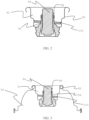
- the present invention is a dispenser ( 20 ) suitable for use with a can having a valve (91) that includes a valve cup (92) surrounding a stationary valve stem housing (94) in which a depressible valve stem (96) resides and which extends out from or is accessible through a top side (98) of the stationary valve stem housing
- the dispenser comprises; (a) a base (36) that has a base side wall (30) separating opposing top (34) and bottom (33) ends with an entrance opening (35) to a flow channel (38) defined through the bottom end with the flow channel extending through the base within the base side wall and through an exit end; (b) a bendable segment (40) having a bendable segment side wall (42) separating opposing bottom (48) and top (43) ends and a flow channel (44) defined through the bottom of the bendable segment that extends through the bendable segment between the side wall and out the top end, where the bottom of the bendable segment is attached to the base so that there is fluid communication between the flow channel of the base and the flow channel
- the present invention is useful for dispensing fluid from a can of compressed fluid that has a Pageris-type valve.
- Fluid refers to a substance that has no fixed shape and yields to external pressure and includes gas, liquid, and gas or liquid continuous formulations. Typically, though not necessarily, fluid refers to liquid and liquid continuous formulations as used herein.
- orientation references are in reference to the direction of fluid flow from the can of the article through the dispenser flow channel as described in this paragraph.
- Terms referring to an elevated position of an element such as “top” or “above” refer to the portion of the element furthest along the direction of fluid flow.
- Terms referring to an elevating direction such as “up” refers to the direction of fluid flow as it is dispensed through the dispenser.
- Terms referring to a subordinate position of an element such as “bottom” or “below” refer to the portion of the element least far along the direction of fluid flow.
- Terms referring to a subordinate direction such as “down” refer to the opposite direction of fluid flow as it is dispensed through the dispenser.
- Figures 1-4 do not illustrate the full breadth of the invention but only embodiments of the elements of the invention to illustrate how they can fit together or be manifest.
- the broadest scope of the invention is intended to allow for embodiments of components as taught herein to be combined in any way physically allowable within the scope of the appended claims and not be specifically limited to that illustrated in Figures 1-4 .
- Figures 1-4 do illustrate embodiments of the invention.
- the article (10) comprises a dispenser (20).
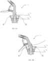
- Figure 1 illustrates an example of a dispenser of the present invention.
- the dispenser comprises a base (36), a bendable segment (40), a straw (50), a plunger (60), a sleeve (70) and a trigger (80).
- the base has opposing bottom (33) and top ends (34) with a base side wall (30) extending between the bottom end and top end.
- the bottom has an entrance opening (35) defined therethrough.
- a flow channel (38) extends through the entrance opening through the base within the base side wall and through to the top of the base.
- the base side wall defines the flow channel through the base with the "inside” of the base side wall exposed within the flow channel and the "outside” of the base side wall external to the flow channel.
- Threads (39) can be defined on the outside of the base side wall ( Figure 1 ). The threads are useful for screwing the base into the cup of a Pageris-type valve (for example, Figure 4 ) that has mating threads as described below.
- the bendable segment (40) has opposing bottom (48) and top (43) ends with a bendable segment side wall (42) extending between the top end and bottom end.
- a flow channel (44) extends all the way through the bendable segment, through the bottom end and the top end.
- the bendable segment is attached such that the bottom end of the bendable segment attaches to the base proximate to the top end of the base such that there is fluid communication between the flow channel of the base and the flow channel of the bendable segment.
- the bendable segment and base can attach such that the top of the base and bottom of the bendable segment coincide. It is also conceivable that the bendable segment slips over a portion of the base (or vice versa) such that the top of the base is between the top and bottom of the bendable segment.
- the bendable segment side wall comprises a compressible feature (49).
- the compressible feature enables the bendable segment to reversibly tilt with respect to the base.
- suitable compressible features include one or more than one indentation in the bendable segment side wall, one or more fold in the bendable segment side wall, or a corrugated section of the bendable segment side wall.
- the bendable segment has a neutral position in which the compressible feature is uncompressed.
- the flow channel of the base and flow channel of the bendable segment are in a straight line when the bendable segment is in its neutral position.
- the can is closed when the bendable segment is in its neutral position.
- the straw (50) has opposing entrance (53) and exit (54) ends separated by a straw wall (52).
- a straw flow channel (58) within the straw wall is defined by the straw wall) through the entrance end and through an exit opening (56) proximate to the exit end.
- the exit opening can be through the exit end of the straw or can be through the straw wall proximate to the exit end.
- the straw can have one exit opening or multiple exit openings.
- the straw is attached to the bendable segment with the straw entrance end proximate to the bendable segment top end.
- the top of the bendable segment and the entrance end of the straw can coincide.
- the straw wall can slip over the bendable segment wall (or vice versa) so that the top end of bendable segments is between the entrance and exit ends of the straw.
- the straw and bendable segment are attached such that the flow channel of the bendable segment is in fluid communication with the flow channel of the straw.
- the flow channels of the base, bendable segment and straw are all in fluid communication and form a dispenser flow channel through the dispenser that extends from the entrance opening of the base through the base, through the bendable segment and through the straw and out through the exit opening of the straw.
- the dispenser flow channel can extend in a straight line all the way through the base, bendable segment and straw.
- the dispenser flow channel can extend in a straight line through the base and bendable segment and then bend at an angle within the straw.
- the straw can have an elbow section (500) and a straight section (510) as shown in Figures 1 and 4 .
- the benefit of including an elbow section is to allow the dispenser to direct fluid flow at a more convenient angle than straight in line out from the top of a can.
- a plunger (60) is attached to the straw proximate to the straw entrance end or the bendable segment proximate to its entrance end and extends within the flow channel of bendable segment towards and optionally into the base flow channel. While the plunger extends within the flow channel, it does not block fluid communication through the flow channel. In that regard, the plunger is of sufficient dimensions and/or design so as to allow fluid communication around and/or through it within the flow channel of the bendable segment and through the dispenser flow channel. For example, the plunger can have a narrower diameter than the diameter of the flow channel in which it resides. Additionally, or alternatively, the plunger can have a design that includes one or more than one hole defined through it that allows fluid flow through the plunger.
- the plunger can essentially be an extension of the straw into the flow channel of the bendable segment with the bendable segment side wall attached to the straw wall above the entrance of the straw and between the entrance and exit ends.
- the dispenser in Figures 1 and 4 illustrates a plunger that can be viewed as an extension of the straw into the flow channel of the bendable segment.
- the plunger has a hole (62), or flow channel, defined through it that provides fluid communication through the plunger and between the flow channel of the bendable segment and the straw.
- the sleeve (70) extends over at least a portion of the straw.
- the sleeve can extend over the exit end of the straw. Alternatively, the sleeve can be free of a portion that extends over the exit end of the straw.
- the sleeve has an exit opening (72) extending through the sleeve proximate to the exit end of the straw. When fluid is dispensed through the dispenser it travels through the flow channel of the dispenser and out from the exit opening of the straw and through the exit opening in the sleeve.
- a gasket extending circumferentially around the straw between the entrance opening and exit opening of the straw (preferably, proximate to the exit opening) and between the sleeve and the straw that contacts both the sleeve and straw wall so as to form a seal between the two around the straw.
- a gasket serves to preclude fluid from flowing between the straw and sleeve.
- Suitable gaskets include an O-ring. The gasket can reside in a groove in the straw wall, the sleeve, both the sleeve and straw wall, or just reside freely without residing in any groove.
- the sleeve is able to slide over the straw along the straw wall. Desirably, the sleeve slides along the straw between a "closed position” and an “open position". When the sleeve is in a “closed position” it seals all exit openings of the straw, preventing fluid flow from the dispenser flow channel through exit opening(s) in the straw. When the sleeve is in an "open position” the sleeve is free from at least one exit opening of the straw meaning fluid is free to flow from the flow channel through the straw and through the exit opening of the straw. Desirably, sliding the sleeve towards the exit end of the straw when the sleeve is in a closed position moves the sleeve into an open position. Similarly, sliding the sleeve towards the entrance end of the straw when the sleeve is in an open position will move the sleeve into a closed position.
- the sleeve When the sleeve is in a closed position the sleeve seals the exit opening of the straw. This precludes dripping of fluid from the dispenser when closed.
- the means of sealing the exit end of the straw is without limit.
- the sleeve can press against the straw wall around and extend over the exit opening thereby blocking fluid communication from the straw flow channel through the exit opening of the straw. Examples of such a means of the sleeve sealing the exit opening of the straw are taught in WO2017/139128 .
- the straw can have a tapered exit end with one or multiple exit openings and the sleeve can have a tapered exit end that conforms to the taper on the straw and presses against the straw when in the closed position so as to seal the exit opening(s) of the straw.
- the sleeve can additionally or alternatively comprise a protrusion that extends at least partially into the exit opening of the straw to seal the exit opening when in the closed position. Examples of such means by which the sleeve seals the exit opening of the straw when in the closed position are taught in WO2017/139131 .
- the exit opening of the straw can be through the exit end of the straw and the sleeve can define a protrusion that extends into the exit opening of the straw when in the closed position.
- the sleeve desirably has one or more than one exit opening around the protrusion to allow fluid flow out from between the straw and sleeve when in the open position.
- the straw can have one or more than one exit opening through the straw wall proximate to but not on the exit end of the straw and the sleeve can have a protrusion for each exit opening of the straw that fits into each exit opening to seal them when the sleeve is in the closed position.
- the sleeve can either extend over the exit end of the straw and have exit opening(s) through its wall or be free of any portion of sleeve that extends over the exit end of the straw and essentially have an exit opening over the exit end of the straw.
- the straw can have a protrusion around which a portion of the trigger extends and a pin can extend through the protrusion and portion of the trigger to establish a hinged attachment.
- the trigger can attach to the straw by means of a flexible material or an article comprising a flexible or compressible element that allows for hinged bending of the trigger with respect to the straw.
- the trigger has a sleeve engagement portion (84) that engages the sleeve above the hinge point. That is, the location where the sleeve engagement portion engages the sleeve is closer to the exit opening of the sleeve than where the trigger hingedly attaches to the straw.
- the sleeve engagement portion can engage the sleeve in any manner that allows movement of the sleeve engagement portion relative to the straw to cause the sleeve to move along the straw wall.
- the sleeve engagement portion can engage the sleeve by extending protrusions on either side of the sleeve within a groove defined on the sleeve.
- the sleeve engagement portion can define an eyelet that extends circumferentially around the sleeve and that resides at least partially within a groove of the sleeve and/or between protrusions in the sleeve.
- the sleeve engagement portion can flexibly attach to the sleeve.
- the means by which the sleeve engagement portion engages the sleeve is unlimited provided that it allows displacement of the sleeve engagement portion relative to the straw to induce the sleeve to slide along the straw wall.
- the trigger has a trigger arm (86) that extends below the hinge point and generally radially out from the straw. That is, the trigger arm extends from the hinge point in a direction generally opposite from the sleeve engagement portion so that moving the trigger arm in the general direction of the dispenser base causes the trigger to hinge at the hinge point and displace the sleeve engagement portion towards the exit end of the straw.
- the trigger arm is generally long enough to allow a user's finger to be placed on it and to apply pressure to the trigger arm in order to actuate the sleeve to an open position from a closed position.
- the trigger and trigger arm are in a "closed" position when located so as to allow the sleeve to be in a closed position.
- the trigger and trigger arm are in an "open" position when they are located in a position that causes the sleeve to be in an open position. Depressing the trigger arm generally towards the base while in the closed position typically displaces the trigger arm and sleeve into their open positions.
- the elastic element located between the trigger arm and base and/or straw that establishes a force on the trigger arm directing the trigger arm to a closed position while in the open position.
- the elastic element can be a spring that is compressed when a force is applied to the trigger that moves it from its closed position to its open position and a restorative force of the spring applies a force to restore the trigger to its closed position when the applied force is removed.
- the straw further comprises a protrusion (59) extending towards the trigger arm, generally radially out from the straw.
- the protrusion acts as a stop against which the trigger arm presses when moved to an open position. Applying further force to the trigger arm in the direction of the open position when the trigger arm contacts the protrusion (59) causes the dispenser to bend at the compressible feature of the bendable segment.
- the dispenser can have a protrusion (59) with a spring serving as an elastic element (88) residing over the protrusion, as illustrated in Figures 1 and 4 .
- the article of the present invention can further comprise a can (90) having a Pageris-type valve (91).
- a Pageris-type valve has a valve cup (92) around a stationary valve stem housing (94) in which a depressible valve stem (96) resides.
- the depressible valve stem extends out from the top (98) of the stationary valve stem housing or is accessible within the valve stem housing through the top of the valve stem housing.
- the stationary valve stem housing is typically a cylindrical structure.
- the stationary valve stem housing is rigidly attached to the valve cup so that it cannot tip, bend or compress relative to the valve cup.
- the stationary valve stem housing serves the purpose of protecting the valve stem from accidentally being depressed.
- Depressing the valve stem opens the valve and provides fluid communication from inside the can to outside the can, releasing pressurized fluid that is within the can.
- the valve stem is depressed so as to open the valve then the valve and valve stem are in an "open position", otherwise they are in a "closed position".
- the valve stem is in the closed position the can is sealed shut.
- the pressure from the can, or an elastic element (such as a spring) between the valve cup and valve stem keeps the valve stem in a closed position until actively depressed to the open position.
- the dispenser attaches to the valve of the can by inserting the base into the valve cup while inserting the stationary valve stem housing into the entrance opening of the base.
- the valve cup has threading (100) defined in it that mates with threading (39) on the outside wall of the base facilitating screwing the base into the valve cup to attach the dispenser to the valve.
- the dispenser When attached to a Pageris-type valve of a can, the dispenser acts as a single-action dispenser that, with a single action, can both move the dispenser from a closed position to an open position and open the valve of the can. Likewise, a single action can close the can and move the dispenser from an open position to a closed position.
- the plunger of the dispenser desirably extends far enough into the flow channel of the dispenser so that when the dispenser is attached to the valve of a can, the valve remains closed when the dispenser is closed, yet far enough that the plunger depresses the valve stem sufficiently to open the valve when the bendable segment is tilted from its neutral position to a tilted position.
- the sleeve slides to an open position and the bendable segment moves from a neutral position to a tilted position thereby opening the valve of the can.
- moving the trigger arm up (away from the can) when the can and dispenser are in an open configuration allows the Pageris-valve to close and the dispenser to move into a closed orientation.
- the dispenser precludes dripping of fluid out from the straw when it is in the closed position but only requires a single action to dispense fluid from a can having a Pageris-type valve.
Landscapes
- Chemical & Material Sciences (AREA)
- Dispersion Chemistry (AREA)
- Engineering & Computer Science (AREA)
- Mechanical Engineering (AREA)
- Containers And Packaging Bodies Having A Special Means To Remove Contents (AREA)
- Nozzles (AREA)
Claims (6)
- Artikel (10), der eine Abgabevorrichtung (20) umfasst, die zur Verwendung mit einer Dose geeignet ist, die ein Ventil (91) aufweist, das einen Ventilbecher (92) einschließt, der ein unbewegliches Ventilschaftgehäuse (94) umgibt, in dem ein niederdrückbarer Ventilschaft (96) sitzt und der sich aus einer oberen Seite (98) des unbeweglichen Ventilschaftgehäuses heraus erstreckt oder durch dieselbe zugänglich ist,
wobei die Abgabevorrichtung Folgendes umfasst:(a) eine Basis (36), die eine Basisseitenwand (30) aufweist, die ein oberes (34) und ein entgegengesetztes unteres (33) Ende trennt, mit einer Eintrittsöffnung (35) zu einem Durchflusskanal (38), der durch das untere Ende definiert wird, wobei sich der Durchflusskanal durch die Basis innerhalb der Basisseitenwand und durch ein Austrittsende erstreckt;(b) ein biegsames Segment (40), das eine Seitenwand (42) des biegsamen Segments, die ein unteres (48) und ein entgegengesetztes oberes (43) Ende trennt, und einen Durchflusskanal (44), der durch die Unterseite des biegsamen Segments definiert wird, der sich durch das biegsame Segment zwischen der Seitenwand und aus dem oberen Ende heraus erstreckt, aufweist, worin die Unterseite des biegsamen Segments an der Basis angebracht ist, sodass es eine Fluidverbindung zwischen dem Durchflusskanal der Basis und dem Durchflusskanal des biegsamen Segments gibt, wobei die Seitenwand ein zusammendrückbares Merkmal (49) umfasst, das es ermöglicht, dass das biegsame Segment von einer neutralen Stellung zu einer gekippten Stellung im Verhältnis zu der Basis kippt;(c) ein Röhrchen (50), das ein Eintritts- (53) und ein entgegengesetztes Austrittsende (54) aufweist, die durch eine Röhrchenwand (52) getrennt werden, worin die Röhrchenwand einen Durchflusskanal (58) definiert, der sich innerhalb der Röhrchenwand durch das Eintrittsende und durch eine Austrittsöffnung (56) nahe dem Austrittsende des Röhrchens erstreckt;(d) einen Kolben (60), der an dem Röhrchen nahe dem Röhrcheneintrittsende oder an dem biegsamen Segment nahe dessen Austrittsende angebracht ist, worin sich der Kolben innerhalb des Durchflusskanals des biegsamen Segments hin zu dem Durchflusskanal der Basis und wahlweise in denselben erstreckt und worin der Kolben Abmessungen und/oder eine Gestaltung aufweist, sodass er eine Fluidverbindung um und/oder durch ihn innerhalb des Durchflusskanals des biegsamen Segments ermöglicht;(e) eine Hülse (70), die sich über mindestens einen Abschnitt des Röhrchens erstreckt und die dazu in der Lage ist, entlang mindestens eines Abschnitts der Röhrchenwand über das Röhrchen zu gleiten, wobei die Hülse eine Austrittsöffnung (72) aufweist, die sich nahe dem Austrittsende des Röhrchens durch sie erstreckt; und(f) einen Auslöser (80), der gelenkig gelagert an einem Gelenkpunkt (82) an dem Röhrchen angebracht ist und einen Abschnitt (84) des Auslösers, der die Hülse oberhalb des Gelenkpunktes in Eingriff nimmt, und einen Auslöserarm (86), der sich unterhalb des Gelenkpunktes erstreckt, aufweist, sodass der Auslöser durch Bewegen des Auslöserarms die Hülse bewegen kann, ohne das Röhrchen zu bewegen, wobei(g) die Hülse, die dazu in der Lage ist, über das Röhrchen entlang der Röhrchenwand zu gleiten, dadurch eine geschlossene Stellung im Verhältnis zu dem Röhrchen aufweist, in der die Hülse die Austrittsöffnung des Röhrchens abdichtet, und wenn sich die Hülse aus der geschlossenen Stellung weg von dem Eintrittsende des Röhrchens bewegt, sie die Austrittsöffnung des Röhrchens entsperrt, was bewirkt, dass sich die Hülse in einer offenen Stellung befindet, in der eine Fluidverbindung von dem Röhrchendurchflusskanal durch die Röhrchenaustrittsöffnung und durch die Hülsenaustrittsöffnung besteht,wobei(i) die Abgabevorrichtung durch Einsetzen des unbeweglichen Ventilschaftgehäuses in die Eintrittsöffnung des Durchflusskanals der Abgabevorrichtungsbasis an dem Ventil der Dose angebracht werden kann, während die Abgabevorrichtungsbasis in den Ventilbecher des Ventils eingesetzt wird, und(ii) der Kolben des Röhrchens dazu in der Lage ist, sich weit genug in den Durchflusskanal des biegsamen Segments zu erstrecken, um so den niederdrückbaren Ventilschaft zusammenzudrücken, um das Ventil zu öffnen, wenn sich das biegsame Segment in einer gekippten Stellung befindet, aber nicht so weit, um den Ventilschaft zu einer offenen Stellung zusammenzudrücken, wenn sich das biegsame Segment in seiner neutralen Stellung befindet. - Artikel nach Anspruch 1, wobei das Röhrchen einen Vorsprung (59) zwischen dort, wo der Gelenkpunkt sitzt, und dort, wo das biegsame Segment sitzt, aufweist, sodass sich der Vorsprung von dem Röhrchen hin zu dem Auslöserarm des Auslösers erstreckt.
- Artikel nach Anspruch 1, wobei das zusammendrückbare Merkmal, das in der Wand des biegsamen Segments definiert ist, ein gewellter Bereich der Wand ist.
- Artikel nach Anspruch 1, wobei ein elastisches Element (88) zwischen dem Auslöserarm und dem Röhrchen der Abgabevorrichtung sitzt, das eine Rückstellkraft ausübt, die den Auslöserarm hin zu seiner neutralen Stellung führt, wenn der Auslöserarm hin zu der Abgabevorrichtungsbasis verschoben wird.
- Artikel nach Anspruch 1, wobei die Abgabevorrichtung ferner mindestens eine Dichtung (51) umfasst, die umlaufend um das Röhrchen zwischen dem Röhrchen und der Hülse positioniert ist und zwischen dem Eintritts- und dem Austrittsende des Röhrchens positioniert ist.
- Artikel nach Anspruch 1, wobei eine Außenfläche der Basiswand ein Gewinde (100) aufweist, das dazu in der Lage ist, mit einem Gewinde zusammenzupassen, das auf einer Innenfläche des Ventilbechers bereitgestellt ist.
Priority Applications (1)
| Application Number | Priority Date | Filing Date | Title |
|---|---|---|---|
| EP23218743.5A EP4324568A3 (de) | 2018-04-10 | 2019-04-10 | Verteiler für ventil mit feststehendem ventilkörpergehäuse |
Applications Claiming Priority (2)
| Application Number | Priority Date | Filing Date | Title |
|---|---|---|---|
| US201862655292P | 2018-04-10 | 2018-04-10 | |
| PCT/US2019/026729 WO2019199927A1 (en) | 2018-04-10 | 2019-04-10 | Dispenser for valve with stationary valve stem housing |
Related Child Applications (1)
| Application Number | Title | Priority Date | Filing Date |
|---|---|---|---|
| EP23218743.5A Division EP4324568A3 (de) | 2018-04-10 | 2019-04-10 | Verteiler für ventil mit feststehendem ventilkörpergehäuse |
Publications (2)
| Publication Number | Publication Date |
|---|---|
| EP3774592A1 EP3774592A1 (de) | 2021-02-17 |
| EP3774592B1 true EP3774592B1 (de) | 2024-01-31 |
Family
ID=66248848
Family Applications (2)
| Application Number | Title | Priority Date | Filing Date |
|---|---|---|---|
| EP19719116.6A Active EP3774592B1 (de) | 2018-04-10 | 2019-04-10 | Verteiler für ventil mit feststehendem ventilkörpergehäuse |
| EP23218743.5A Pending EP4324568A3 (de) | 2018-04-10 | 2019-04-10 | Verteiler für ventil mit feststehendem ventilkörpergehäuse |
Family Applications After (1)
| Application Number | Title | Priority Date | Filing Date |
|---|---|---|---|
| EP23218743.5A Pending EP4324568A3 (de) | 2018-04-10 | 2019-04-10 | Verteiler für ventil mit feststehendem ventilkörpergehäuse |
Country Status (6)
| Country | Link |
|---|---|
| US (1) | US10611554B2 (de) |
| EP (2) | EP3774592B1 (de) |
| JP (1) | JP7275160B2 (de) |
| CN (1) | CN112236373B (de) |
| CA (1) | CA3095790A1 (de) |
| WO (1) | WO2019199927A1 (de) |
Families Citing this family (6)
| Publication number | Priority date | Publication date | Assignee | Title |
|---|---|---|---|---|
| US10226782B2 (en) * | 2013-11-29 | 2019-03-12 | Daizo Corporation | Content-accommodating container, content-accommodating product using same, discharge product, and discharge device |
| EP3529174B8 (de) * | 2016-10-20 | 2021-05-05 | DDP Specialty Electronic Materials US, LLC | Einfingerausgabeartikel |
| BE1024213B1 (nl) * | 2016-11-04 | 2017-12-13 | Altachem Nv | Klep |
| EP3339212B1 (de) | 2016-12-23 | 2021-03-31 | DOC-BIBAWO ApS | Aerosolspender und behälter und köpfe für solche behälter |
| US12269668B2 (en) * | 2022-01-12 | 2025-04-08 | Seymour Of Sycamore Inc. | Aerosol can activator |
| US12516198B2 (en) | 2022-07-21 | 2026-01-06 | Dap Global Inc. | One-component spray foam compositions and dispensers thereof |
Family Cites Families (19)
| Publication number | Priority date | Publication date | Assignee | Title |
|---|---|---|---|---|
| US3506241A (en) | 1967-07-06 | 1970-04-14 | Pittsburgh Railways Co | Tilt valve |
| US4436229A (en) | 1982-08-05 | 1984-03-13 | Beard Walter C | High flow tilt valve with accelerating cam equipped moveable cup |
| US4450984A (en) * | 1982-08-05 | 1984-05-29 | Beard Walter C | Viscous flow tilt valve for pressurized container |
| US4856684A (en) | 1987-04-06 | 1989-08-15 | William Gerstung | Valve for a pressurized dispensing can containing flowable materials |
| DE4313319B4 (de) * | 1993-04-23 | 2006-09-28 | C. Ehrensperger Ag | Vorrichtung für Betätigungsvorrichtungen für Treibmitteldosen |
| AU688454B2 (en) * | 1994-01-14 | 1998-03-12 | Werner Morck | Container with locked valve adapter |
| US5702036A (en) * | 1995-09-07 | 1997-12-30 | Precision Valve Corporation | Aerosol total release actuator having a delay in product emission |
| JP3096635U (ja) * | 2003-03-24 | 2003-09-26 | 株式会社ソフト99コーポレーション | エアゾール容器のレバー付きノズル |
| GB0307445D0 (en) * | 2003-03-31 | 2003-05-07 | Glaxo Group Ltd | Novel device |
| EE05028B1 (et) * | 2006-03-31 | 2008-06-16 | O� Krimelte | Ksiaplikaatori kinnitus |
| BE1020534A5 (nl) | 2010-06-04 | 2013-12-03 | Soudal | Schroefkoppelstuk met dubbele functie. |
| US20120097180A1 (en) * | 2010-10-21 | 2012-04-26 | Henkel Consumer Goods Inc. | Actuator for dispensing aerosol hair care products closer to the scalp |
| EP2658796B1 (de) | 2011-02-25 | 2015-07-22 | Dow Global Technologies LLC | Vorrichtung mit interner dichtung zur ausgabe eines komprimierten fluids |
| WO2012115841A1 (en) * | 2011-02-25 | 2012-08-30 | Dow Global Technologies Llc | Sleeve activated compressed fluid dispensing device with internal seal |
| US9010572B2 (en) * | 2012-12-11 | 2015-04-21 | Altachem N. V. | Tip seal having a position indicator, the tip seal being configured to dispense a foam solution |
| BE1022385B1 (nl) * | 2015-02-02 | 2016-03-18 | Altachem N.V. | Een bevestigingsgeheel voor het bevestigen van een adapter aan een ventielsteel. |
| CA3003175C (en) | 2015-10-27 | 2023-09-26 | Dow Global Technologies Llc | Cap with nested handle for spray can |
| JP6805260B6 (ja) | 2016-02-09 | 2021-01-20 | ディディピー スペシャリティ エレクトロニック マテリアルズ ユーエス エルエルシー | 摺動スリーブを有する単動式分注装置 |
| HUE054952T2 (hu) | 2016-02-09 | 2021-10-28 | Ddp Specialty Electronic Materials Us Llc | Egymûködtetésû adagolóberendezés csúszóhüvellyel, amelynek van dugója |
-
2019
- 2019-04-10 CA CA3095790A patent/CA3095790A1/en active Pending
- 2019-04-10 WO PCT/US2019/026729 patent/WO2019199927A1/en not_active Ceased
- 2019-04-10 JP JP2020551486A patent/JP7275160B2/ja active Active
- 2019-04-10 CN CN201980022011.0A patent/CN112236373B/zh active Active
- 2019-04-10 US US16/380,060 patent/US10611554B2/en active Active
- 2019-04-10 EP EP19719116.6A patent/EP3774592B1/de active Active
- 2019-04-10 EP EP23218743.5A patent/EP4324568A3/de active Pending
Also Published As
| Publication number | Publication date |
|---|---|
| EP3774592A1 (de) | 2021-02-17 |
| CA3095790A1 (en) | 2019-10-17 |
| CN112236373A (zh) | 2021-01-15 |
| US20190308797A1 (en) | 2019-10-10 |
| US10611554B2 (en) | 2020-04-07 |
| JP7275160B2 (ja) | 2023-05-17 |
| JP2021519245A (ja) | 2021-08-10 |
| CN112236373B (zh) | 2022-09-02 |
| WO2019199927A1 (en) | 2019-10-17 |
| EP4324568A2 (de) | 2024-02-21 |
| EP4324568A3 (de) | 2024-05-22 |
Similar Documents
| Publication | Publication Date | Title |
|---|---|---|
| EP3774592B1 (de) | Verteiler für ventil mit feststehendem ventilkörpergehäuse | |
| EP3774591B1 (de) | Spender für dosen mit festem ventilschaftgehäuse | |
| EP3414181B1 (de) | Einfachwirkende spendevorrichtung mit schiebehülse | |
| EP3414182B1 (de) | Einfachwirkende abgabevorrichtung mit schiebehülse mit stopfen | |
| US10919687B2 (en) | Dispenser with cap | |
| US10919688B2 (en) | Single finger dispensing article | |
| US10632486B2 (en) | Dispenser adapter |
Legal Events
| Date | Code | Title | Description |
|---|---|---|---|
| STAA | Information on the status of an ep patent application or granted ep patent |
Free format text: STATUS: UNKNOWN |
|
| STAA | Information on the status of an ep patent application or granted ep patent |
Free format text: STATUS: THE INTERNATIONAL PUBLICATION HAS BEEN MADE |
|
| PUAI | Public reference made under article 153(3) epc to a published international application that has entered the european phase |
Free format text: ORIGINAL CODE: 0009012 |
|
| STAA | Information on the status of an ep patent application or granted ep patent |
Free format text: STATUS: REQUEST FOR EXAMINATION WAS MADE |
|
| 17P | Request for examination filed |
Effective date: 20201020 |
|
| AK | Designated contracting states |
Kind code of ref document: A1 Designated state(s): AL AT BE BG CH CY CZ DE DK EE ES FI FR GB GR HR HU IE IS IT LI LT LU LV MC MK MT NL NO PL PT RO RS SE SI SK SM TR |
|
| AX | Request for extension of the european patent |
Extension state: BA ME |
|
| RAP3 | Party data changed (applicant data changed or rights of an application transferred) |
Owner name: DDP SPECIALTY ELECTRONIC MATERIALS US, LLC |
|
| DAV | Request for validation of the european patent (deleted) | ||
| DAX | Request for extension of the european patent (deleted) | ||
| STAA | Information on the status of an ep patent application or granted ep patent |
Free format text: STATUS: EXAMINATION IS IN PROGRESS |
|
| 17Q | First examination report despatched |
Effective date: 20221014 |
|
| RIC1 | Information provided on ipc code assigned before grant |
Ipc: B05B 11/10 20230101ALN20230720BHEP Ipc: B65D 83/48 20060101ALN20230720BHEP Ipc: B65D 83/30 20060101ALN20230720BHEP Ipc: B65D 83/20 20060101AFI20230720BHEP |
|
| RIC1 | Information provided on ipc code assigned before grant |
Ipc: B05B 11/10 20230101ALN20230803BHEP Ipc: B65D 83/48 20060101ALN20230803BHEP Ipc: B65D 83/30 20060101ALN20230803BHEP Ipc: B65D 83/20 20060101AFI20230803BHEP |
|
| GRAP | Despatch of communication of intention to grant a patent |
Free format text: ORIGINAL CODE: EPIDOSNIGR1 |
|
| STAA | Information on the status of an ep patent application or granted ep patent |
Free format text: STATUS: GRANT OF PATENT IS INTENDED |
|
| INTG | Intention to grant announced |
Effective date: 20230919 |
|
| GRAS | Grant fee paid |
Free format text: ORIGINAL CODE: EPIDOSNIGR3 |
|
| GRAA | (expected) grant |
Free format text: ORIGINAL CODE: 0009210 |
|
| STAA | Information on the status of an ep patent application or granted ep patent |
Free format text: STATUS: THE PATENT HAS BEEN GRANTED |
|
| AK | Designated contracting states |
Kind code of ref document: B1 Designated state(s): AL AT BE BG CH CY CZ DE DK EE ES FI FR GB GR HR HU IE IS IT LI LT LU LV MC MK MT NL NO PL PT RO RS SE SI SK SM TR |
|
| REG | Reference to a national code |
Ref country code: GB Ref legal event code: FG4D Ref country code: CH Ref legal event code: EP |
|
| REG | Reference to a national code |
Ref country code: DE Ref legal event code: R096 Ref document number: 602019045928 Country of ref document: DE |
|
| REG | Reference to a national code |
Ref country code: IE Ref legal event code: FG4D |
|
| REG | Reference to a national code |
Ref country code: LT Ref legal event code: MG9D |
|
| REG | Reference to a national code |
Ref country code: NL Ref legal event code: MP Effective date: 20240131 |
|
| PG25 | Lapsed in a contracting state [announced via postgrant information from national office to epo] |
Ref country code: IS Free format text: LAPSE BECAUSE OF FAILURE TO SUBMIT A TRANSLATION OF THE DESCRIPTION OR TO PAY THE FEE WITHIN THE PRESCRIBED TIME-LIMIT Effective date: 20240531 |
|
| PG25 | Lapsed in a contracting state [announced via postgrant information from national office to epo] |
Ref country code: LT Free format text: LAPSE BECAUSE OF FAILURE TO SUBMIT A TRANSLATION OF THE DESCRIPTION OR TO PAY THE FEE WITHIN THE PRESCRIBED TIME-LIMIT Effective date: 20240131 |
|
| PG25 | Lapsed in a contracting state [announced via postgrant information from national office to epo] |
Ref country code: GR Free format text: LAPSE BECAUSE OF FAILURE TO SUBMIT A TRANSLATION OF THE DESCRIPTION OR TO PAY THE FEE WITHIN THE PRESCRIBED TIME-LIMIT Effective date: 20240501 |
|
| REG | Reference to a national code |
Ref country code: AT Ref legal event code: MK05 Ref document number: 1653744 Country of ref document: AT Kind code of ref document: T Effective date: 20240131 |
|
| PG25 | Lapsed in a contracting state [announced via postgrant information from national office to epo] |
Ref country code: NL Free format text: LAPSE BECAUSE OF FAILURE TO SUBMIT A TRANSLATION OF THE DESCRIPTION OR TO PAY THE FEE WITHIN THE PRESCRIBED TIME-LIMIT Effective date: 20240131 Ref country code: HR Free format text: LAPSE BECAUSE OF FAILURE TO SUBMIT A TRANSLATION OF THE DESCRIPTION OR TO PAY THE FEE WITHIN THE PRESCRIBED TIME-LIMIT Effective date: 20240131 Ref country code: RS Free format text: LAPSE BECAUSE OF FAILURE TO SUBMIT A TRANSLATION OF THE DESCRIPTION OR TO PAY THE FEE WITHIN THE PRESCRIBED TIME-LIMIT Effective date: 20240430 |
|
| PG25 | Lapsed in a contracting state [announced via postgrant information from national office to epo] |
Ref country code: ES Free format text: LAPSE BECAUSE OF FAILURE TO SUBMIT A TRANSLATION OF THE DESCRIPTION OR TO PAY THE FEE WITHIN THE PRESCRIBED TIME-LIMIT Effective date: 20240131 |
|
| PG25 | Lapsed in a contracting state [announced via postgrant information from national office to epo] |
Ref country code: AT Free format text: LAPSE BECAUSE OF FAILURE TO SUBMIT A TRANSLATION OF THE DESCRIPTION OR TO PAY THE FEE WITHIN THE PRESCRIBED TIME-LIMIT Effective date: 20240131 |
|
| PG25 | Lapsed in a contracting state [announced via postgrant information from national office to epo] |
Ref country code: RS Free format text: LAPSE BECAUSE OF FAILURE TO SUBMIT A TRANSLATION OF THE DESCRIPTION OR TO PAY THE FEE WITHIN THE PRESCRIBED TIME-LIMIT Effective date: 20240430 Ref country code: NO Free format text: LAPSE BECAUSE OF FAILURE TO SUBMIT A TRANSLATION OF THE DESCRIPTION OR TO PAY THE FEE WITHIN THE PRESCRIBED TIME-LIMIT Effective date: 20240430 Ref country code: NL Free format text: LAPSE BECAUSE OF FAILURE TO SUBMIT A TRANSLATION OF THE DESCRIPTION OR TO PAY THE FEE WITHIN THE PRESCRIBED TIME-LIMIT Effective date: 20240131 Ref country code: LT Free format text: LAPSE BECAUSE OF FAILURE TO SUBMIT A TRANSLATION OF THE DESCRIPTION OR TO PAY THE FEE WITHIN THE PRESCRIBED TIME-LIMIT Effective date: 20240131 Ref country code: IS Free format text: LAPSE BECAUSE OF FAILURE TO SUBMIT A TRANSLATION OF THE DESCRIPTION OR TO PAY THE FEE WITHIN THE PRESCRIBED TIME-LIMIT Effective date: 20240531 Ref country code: HR Free format text: LAPSE BECAUSE OF FAILURE TO SUBMIT A TRANSLATION OF THE DESCRIPTION OR TO PAY THE FEE WITHIN THE PRESCRIBED TIME-LIMIT Effective date: 20240131 Ref country code: GR Free format text: LAPSE BECAUSE OF FAILURE TO SUBMIT A TRANSLATION OF THE DESCRIPTION OR TO PAY THE FEE WITHIN THE PRESCRIBED TIME-LIMIT Effective date: 20240501 Ref country code: FI Free format text: LAPSE BECAUSE OF FAILURE TO SUBMIT A TRANSLATION OF THE DESCRIPTION OR TO PAY THE FEE WITHIN THE PRESCRIBED TIME-LIMIT Effective date: 20240131 Ref country code: ES Free format text: LAPSE BECAUSE OF FAILURE TO SUBMIT A TRANSLATION OF THE DESCRIPTION OR TO PAY THE FEE WITHIN THE PRESCRIBED TIME-LIMIT Effective date: 20240131 Ref country code: BG Free format text: LAPSE BECAUSE OF FAILURE TO SUBMIT A TRANSLATION OF THE DESCRIPTION OR TO PAY THE FEE WITHIN THE PRESCRIBED TIME-LIMIT Effective date: 20240131 Ref country code: AT Free format text: LAPSE BECAUSE OF FAILURE TO SUBMIT A TRANSLATION OF THE DESCRIPTION OR TO PAY THE FEE WITHIN THE PRESCRIBED TIME-LIMIT Effective date: 20240131 |
|
| PG25 | Lapsed in a contracting state [announced via postgrant information from national office to epo] |
Ref country code: PL Free format text: LAPSE BECAUSE OF FAILURE TO SUBMIT A TRANSLATION OF THE DESCRIPTION OR TO PAY THE FEE WITHIN THE PRESCRIBED TIME-LIMIT Effective date: 20240131 Ref country code: PT Free format text: LAPSE BECAUSE OF FAILURE TO SUBMIT A TRANSLATION OF THE DESCRIPTION OR TO PAY THE FEE WITHIN THE PRESCRIBED TIME-LIMIT Effective date: 20240531 |
|
| PG25 | Lapsed in a contracting state [announced via postgrant information from national office to epo] |
Ref country code: SE Free format text: LAPSE BECAUSE OF FAILURE TO SUBMIT A TRANSLATION OF THE DESCRIPTION OR TO PAY THE FEE WITHIN THE PRESCRIBED TIME-LIMIT Effective date: 20240131 Ref country code: PT Free format text: LAPSE BECAUSE OF FAILURE TO SUBMIT A TRANSLATION OF THE DESCRIPTION OR TO PAY THE FEE WITHIN THE PRESCRIBED TIME-LIMIT Effective date: 20240531 Ref country code: PL Free format text: LAPSE BECAUSE OF FAILURE TO SUBMIT A TRANSLATION OF THE DESCRIPTION OR TO PAY THE FEE WITHIN THE PRESCRIBED TIME-LIMIT Effective date: 20240131 Ref country code: LV Free format text: LAPSE BECAUSE OF FAILURE TO SUBMIT A TRANSLATION OF THE DESCRIPTION OR TO PAY THE FEE WITHIN THE PRESCRIBED TIME-LIMIT Effective date: 20240131 |
|
| PG25 | Lapsed in a contracting state [announced via postgrant information from national office to epo] |
Ref country code: DK Free format text: LAPSE BECAUSE OF FAILURE TO SUBMIT A TRANSLATION OF THE DESCRIPTION OR TO PAY THE FEE WITHIN THE PRESCRIBED TIME-LIMIT Effective date: 20240131 |
|
| PG25 | Lapsed in a contracting state [announced via postgrant information from national office to epo] |
Ref country code: SM Free format text: LAPSE BECAUSE OF FAILURE TO SUBMIT A TRANSLATION OF THE DESCRIPTION OR TO PAY THE FEE WITHIN THE PRESCRIBED TIME-LIMIT Effective date: 20240131 |
|
| PG25 | Lapsed in a contracting state [announced via postgrant information from national office to epo] |
Ref country code: EE Free format text: LAPSE BECAUSE OF FAILURE TO SUBMIT A TRANSLATION OF THE DESCRIPTION OR TO PAY THE FEE WITHIN THE PRESCRIBED TIME-LIMIT Effective date: 20240131 Ref country code: CZ Free format text: LAPSE BECAUSE OF FAILURE TO SUBMIT A TRANSLATION OF THE DESCRIPTION OR TO PAY THE FEE WITHIN THE PRESCRIBED TIME-LIMIT Effective date: 20240131 |
|
| PG25 | Lapsed in a contracting state [announced via postgrant information from national office to epo] |
Ref country code: SK Free format text: LAPSE BECAUSE OF FAILURE TO SUBMIT A TRANSLATION OF THE DESCRIPTION OR TO PAY THE FEE WITHIN THE PRESCRIBED TIME-LIMIT Effective date: 20240131 |
|
| PG25 | Lapsed in a contracting state [announced via postgrant information from national office to epo] |
Ref country code: SM Free format text: LAPSE BECAUSE OF FAILURE TO SUBMIT A TRANSLATION OF THE DESCRIPTION OR TO PAY THE FEE WITHIN THE PRESCRIBED TIME-LIMIT Effective date: 20240131 Ref country code: SK Free format text: LAPSE BECAUSE OF FAILURE TO SUBMIT A TRANSLATION OF THE DESCRIPTION OR TO PAY THE FEE WITHIN THE PRESCRIBED TIME-LIMIT Effective date: 20240131 Ref country code: RO Free format text: LAPSE BECAUSE OF FAILURE TO SUBMIT A TRANSLATION OF THE DESCRIPTION OR TO PAY THE FEE WITHIN THE PRESCRIBED TIME-LIMIT Effective date: 20240131 Ref country code: EE Free format text: LAPSE BECAUSE OF FAILURE TO SUBMIT A TRANSLATION OF THE DESCRIPTION OR TO PAY THE FEE WITHIN THE PRESCRIBED TIME-LIMIT Effective date: 20240131 Ref country code: DK Free format text: LAPSE BECAUSE OF FAILURE TO SUBMIT A TRANSLATION OF THE DESCRIPTION OR TO PAY THE FEE WITHIN THE PRESCRIBED TIME-LIMIT Effective date: 20240131 Ref country code: CZ Free format text: LAPSE BECAUSE OF FAILURE TO SUBMIT A TRANSLATION OF THE DESCRIPTION OR TO PAY THE FEE WITHIN THE PRESCRIBED TIME-LIMIT Effective date: 20240131 |
|
| REG | Reference to a national code |
Ref country code: DE Ref legal event code: R097 Ref document number: 602019045928 Country of ref document: DE |
|
| PG25 | Lapsed in a contracting state [announced via postgrant information from national office to epo] |
Ref country code: MC Free format text: LAPSE BECAUSE OF FAILURE TO SUBMIT A TRANSLATION OF THE DESCRIPTION OR TO PAY THE FEE WITHIN THE PRESCRIBED TIME-LIMIT Effective date: 20240131 |
|
| PG25 | Lapsed in a contracting state [announced via postgrant information from national office to epo] |
Ref country code: MC Free format text: LAPSE BECAUSE OF FAILURE TO SUBMIT A TRANSLATION OF THE DESCRIPTION OR TO PAY THE FEE WITHIN THE PRESCRIBED TIME-LIMIT Effective date: 20240131 |
|
| REG | Reference to a national code |
Ref country code: CH Ref legal event code: PL |
|
| PG25 | Lapsed in a contracting state [announced via postgrant information from national office to epo] |
Ref country code: IT Free format text: LAPSE BECAUSE OF FAILURE TO SUBMIT A TRANSLATION OF THE DESCRIPTION OR TO PAY THE FEE WITHIN THE PRESCRIBED TIME-LIMIT Effective date: 20240131 |
|
| PLBE | No opposition filed within time limit |
Free format text: ORIGINAL CODE: 0009261 |
|
| STAA | Information on the status of an ep patent application or granted ep patent |
Free format text: STATUS: NO OPPOSITION FILED WITHIN TIME LIMIT |
|
| PG25 | Lapsed in a contracting state [announced via postgrant information from national office to epo] |
Ref country code: LU Free format text: LAPSE BECAUSE OF NON-PAYMENT OF DUE FEES Effective date: 20240410 |
|
| PG25 | Lapsed in a contracting state [announced via postgrant information from national office to epo] |
Ref country code: LU Free format text: LAPSE BECAUSE OF NON-PAYMENT OF DUE FEES Effective date: 20240410 Ref country code: IT Free format text: LAPSE BECAUSE OF FAILURE TO SUBMIT A TRANSLATION OF THE DESCRIPTION OR TO PAY THE FEE WITHIN THE PRESCRIBED TIME-LIMIT Effective date: 20240131 |
|
| 26N | No opposition filed |
Effective date: 20241101 |
|
| PG25 | Lapsed in a contracting state [announced via postgrant information from national office to epo] |
Ref country code: CH Free format text: LAPSE BECAUSE OF NON-PAYMENT OF DUE FEES Effective date: 20240430 |
|
| PG25 | Lapsed in a contracting state [announced via postgrant information from national office to epo] |
Ref country code: IE Free format text: LAPSE BECAUSE OF NON-PAYMENT OF DUE FEES Effective date: 20240410 |
|
| PG25 | Lapsed in a contracting state [announced via postgrant information from national office to epo] |
Ref country code: SI Free format text: LAPSE BECAUSE OF FAILURE TO SUBMIT A TRANSLATION OF THE DESCRIPTION OR TO PAY THE FEE WITHIN THE PRESCRIBED TIME-LIMIT Effective date: 20240131 |
|
| PGFP | Annual fee paid to national office [announced via postgrant information from national office to epo] |
Ref country code: BE Payment date: 20250318 Year of fee payment: 7 |
|
| PGFP | Annual fee paid to national office [announced via postgrant information from national office to epo] |
Ref country code: FR Payment date: 20250310 Year of fee payment: 7 |
|
| PGFP | Annual fee paid to national office [announced via postgrant information from national office to epo] |
Ref country code: GB Payment date: 20250306 Year of fee payment: 7 |
|
| PGFP | Annual fee paid to national office [announced via postgrant information from national office to epo] |
Ref country code: DE Payment date: 20250305 Year of fee payment: 7 |
|
| PG25 | Lapsed in a contracting state [announced via postgrant information from national office to epo] |
Ref country code: CY Free format text: LAPSE BECAUSE OF FAILURE TO SUBMIT A TRANSLATION OF THE DESCRIPTION OR TO PAY THE FEE WITHIN THE PRESCRIBED TIME-LIMIT; INVALID AB INITIO Effective date: 20190410 |
|
| PG25 | Lapsed in a contracting state [announced via postgrant information from national office to epo] |
Ref country code: HU Free format text: LAPSE BECAUSE OF FAILURE TO SUBMIT A TRANSLATION OF THE DESCRIPTION OR TO PAY THE FEE WITHIN THE PRESCRIBED TIME-LIMIT; INVALID AB INITIO Effective date: 20190410 |