EP3774570B1 - Couvercle pour un récipient pour produits de tabac sans fumée et procédé de fabrication d'un tel couvercle - Google Patents
Couvercle pour un récipient pour produits de tabac sans fumée et procédé de fabrication d'un tel couvercle Download PDFInfo
- Publication number
- EP3774570B1 EP3774570B1 EP19726486.4A EP19726486A EP3774570B1 EP 3774570 B1 EP3774570 B1 EP 3774570B1 EP 19726486 A EP19726486 A EP 19726486A EP 3774570 B1 EP3774570 B1 EP 3774570B1
- Authority
- EP
- European Patent Office
- Prior art keywords
- cladding
- lid
- laterally
- metallic
- extending wall
- Prior art date
- Legal status (The legal status is an assumption and is not a legal conclusion. Google has not performed a legal analysis and makes no representation as to the accuracy of the status listed.)
- Active
Links
- 235000019505 tobacco product Nutrition 0.000 title claims description 17
- 238000004519 manufacturing process Methods 0.000 title claims description 8
- 238000005253 cladding Methods 0.000 claims description 81
- 239000000463 material Substances 0.000 claims description 41
- 230000002093 peripheral effect Effects 0.000 claims description 40
- 238000000576 coating method Methods 0.000 claims description 24
- 239000012790 adhesive layer Substances 0.000 claims description 23
- 239000011248 coating agent Substances 0.000 claims description 21
- 238000000034 method Methods 0.000 claims description 18
- 239000000853 adhesive Substances 0.000 claims description 15
- 230000001070 adhesive effect Effects 0.000 claims description 15
- 230000006698 induction Effects 0.000 claims description 8
- 238000007639 printing Methods 0.000 claims description 3
- 238000004049 embossing Methods 0.000 claims 1
- 241000208125 Nicotiana Species 0.000 description 40
- 235000002637 Nicotiana tabacum Nutrition 0.000 description 40
- 239000000047 product Substances 0.000 description 35
- 239000000203 mixture Substances 0.000 description 14
- 241000282836 Camelus dromedarius Species 0.000 description 12
- 239000002184 metal Substances 0.000 description 10
- 229910052751 metal Inorganic materials 0.000 description 10
- 238000009472 formulation Methods 0.000 description 9
- -1 polyethylene Polymers 0.000 description 7
- 238000003860 storage Methods 0.000 description 6
- 238000004806 packaging method and process Methods 0.000 description 5
- 238000007789 sealing Methods 0.000 description 5
- 238000002372 labelling Methods 0.000 description 4
- 239000004033 plastic Substances 0.000 description 4
- 229920003023 plastic Polymers 0.000 description 4
- 230000008569 process Effects 0.000 description 4
- 239000000758 substrate Substances 0.000 description 4
- 239000004698 Polyethylene Substances 0.000 description 3
- 229910000831 Steel Inorganic materials 0.000 description 3
- 239000006185 dispersion Substances 0.000 description 3
- 239000004615 ingredient Substances 0.000 description 3
- 230000014759 maintenance of location Effects 0.000 description 3
- 229920000573 polyethylene Polymers 0.000 description 3
- 239000010959 steel Substances 0.000 description 3
- XKRFYHLGVUSROY-UHFFFAOYSA-N Argon Chemical compound [Ar] XKRFYHLGVUSROY-UHFFFAOYSA-N 0.000 description 2
- IJGRMHOSHXDMSA-UHFFFAOYSA-N Atomic nitrogen Chemical compound N#N IJGRMHOSHXDMSA-UHFFFAOYSA-N 0.000 description 2
- PXHVJJICTQNCMI-UHFFFAOYSA-N Nickel Chemical compound [Ni] PXHVJJICTQNCMI-UHFFFAOYSA-N 0.000 description 2
- 240000007594 Oryza sativa Species 0.000 description 2
- 235000007164 Oryza sativa Nutrition 0.000 description 2
- 239000004952 Polyamide Substances 0.000 description 2
- 239000004743 Polypropylene Substances 0.000 description 2
- 239000004793 Polystyrene Substances 0.000 description 2
- ATJFFYVFTNAWJD-UHFFFAOYSA-N Tin Chemical compound [Sn] ATJFFYVFTNAWJD-UHFFFAOYSA-N 0.000 description 2
- 239000012298 atmosphere Substances 0.000 description 2
- QVGXLLKOCUKJST-UHFFFAOYSA-N atomic oxygen Chemical compound [O] QVGXLLKOCUKJST-UHFFFAOYSA-N 0.000 description 2
- 230000004888 barrier function Effects 0.000 description 2
- 239000011230 binding agent Substances 0.000 description 2
- 230000001055 chewing effect Effects 0.000 description 2
- 239000011247 coating layer Substances 0.000 description 2
- 230000007613 environmental effect Effects 0.000 description 2
- 238000005530 etching Methods 0.000 description 2
- 238000010438 heat treatment Methods 0.000 description 2
- 238000002347 injection Methods 0.000 description 2
- 239000007924 injection Substances 0.000 description 2
- 238000001746 injection moulding Methods 0.000 description 2
- 239000007769 metal material Substances 0.000 description 2
- 238000000465 moulding Methods 0.000 description 2
- 239000001301 oxygen Substances 0.000 description 2
- 229910052760 oxygen Inorganic materials 0.000 description 2
- 239000008188 pellet Substances 0.000 description 2
- 229920002647 polyamide Polymers 0.000 description 2
- 229920001155 polypropylene Polymers 0.000 description 2
- 229920002223 polystyrene Polymers 0.000 description 2
- 238000009877 rendering Methods 0.000 description 2
- 235000009566 rice Nutrition 0.000 description 2
- 239000007787 solid Substances 0.000 description 2
- 239000012265 solid product Substances 0.000 description 2
- 239000000126 substance Substances 0.000 description 2
- 229910052718 tin Inorganic materials 0.000 description 2
- 238000013022 venting Methods 0.000 description 2
- XLYOFNOQVPJJNP-UHFFFAOYSA-N water Substances O XLYOFNOQVPJJNP-UHFFFAOYSA-N 0.000 description 2
- 229910001369 Brass Inorganic materials 0.000 description 1
- 229910000906 Bronze Inorganic materials 0.000 description 1
- 229920002134 Carboxymethyl cellulose Polymers 0.000 description 1
- 235000006679 Mentha X verticillata Nutrition 0.000 description 1
- 235000002899 Mentha suaveolens Nutrition 0.000 description 1
- 235000001636 Mentha x rotundifolia Nutrition 0.000 description 1
- 244000046052 Phaseolus vulgaris Species 0.000 description 1
- 235000010627 Phaseolus vulgaris Nutrition 0.000 description 1
- 206010036790 Productive cough Diseases 0.000 description 1
- 239000004373 Pullulan Substances 0.000 description 1
- 229920001218 Pullulan Polymers 0.000 description 1
- 229920001131 Pulp (paper) Polymers 0.000 description 1
- 240000007591 Tilia tomentosa Species 0.000 description 1
- NIXOWILDQLNWCW-UHFFFAOYSA-N acrylic acid group Chemical group C(C=C)(=O)O NIXOWILDQLNWCW-UHFFFAOYSA-N 0.000 description 1
- 239000000654 additive Substances 0.000 description 1
- 235000010443 alginic acid Nutrition 0.000 description 1
- 229920000615 alginic acid Polymers 0.000 description 1
- 229910052782 aluminium Inorganic materials 0.000 description 1
- XAGFODPZIPBFFR-UHFFFAOYSA-N aluminium Chemical compound [Al] XAGFODPZIPBFFR-UHFFFAOYSA-N 0.000 description 1
- 239000003963 antioxidant agent Substances 0.000 description 1
- 229910052786 argon Inorganic materials 0.000 description 1
- 239000011324 bead Substances 0.000 description 1
- 239000010951 brass Substances 0.000 description 1
- 239000010974 bronze Substances 0.000 description 1
- 239000001768 carboxy methyl cellulose Substances 0.000 description 1
- 235000010948 carboxy methyl cellulose Nutrition 0.000 description 1
- 239000008112 carboxymethyl-cellulose Substances 0.000 description 1
- 238000005266 casting Methods 0.000 description 1
- 235000013339 cereals Nutrition 0.000 description 1
- 230000008859 change Effects 0.000 description 1
- 239000003086 colorant Substances 0.000 description 1
- 239000002131 composite material Substances 0.000 description 1
- 238000001816 cooling Methods 0.000 description 1
- KUNSUQLRTQLHQQ-UHFFFAOYSA-N copper tin Chemical compound [Cu].[Sn] KUNSUQLRTQLHQQ-UHFFFAOYSA-N 0.000 description 1
- 230000008878 coupling Effects 0.000 description 1
- 238000010168 coupling process Methods 0.000 description 1
- 238000005859 coupling reaction Methods 0.000 description 1
- 238000002788 crimping Methods 0.000 description 1
- 230000001419 dependent effect Effects 0.000 description 1
- 238000004090 dissolution Methods 0.000 description 1
- 239000000975 dye Substances 0.000 description 1
- 230000000694 effects Effects 0.000 description 1
- 230000005672 electromagnetic field Effects 0.000 description 1
- 239000000839 emulsion Substances 0.000 description 1
- 239000004744 fabric Substances 0.000 description 1
- 239000000945 filler Substances 0.000 description 1
- 239000010419 fine particle Substances 0.000 description 1
- 239000000796 flavoring agent Substances 0.000 description 1
- 239000011888 foil Substances 0.000 description 1
- 235000013355 food flavoring agent Nutrition 0.000 description 1
- 235000003599 food sweetener Nutrition 0.000 description 1
- 230000010354 integration Effects 0.000 description 1
- 230000001788 irregular Effects 0.000 description 1
- 238000005304 joining Methods 0.000 description 1
- 239000011159 matrix material Substances 0.000 description 1
- 230000004048 modification Effects 0.000 description 1
- 238000012986 modification Methods 0.000 description 1
- 229910052759 nickel Inorganic materials 0.000 description 1
- 229910052757 nitrogen Inorganic materials 0.000 description 1
- 238000012858 packaging process Methods 0.000 description 1
- 238000012856 packing Methods 0.000 description 1
- 230000035699 permeability Effects 0.000 description 1
- 239000012466 permeate Substances 0.000 description 1
- 229920000098 polyolefin Polymers 0.000 description 1
- 238000002360 preparation method Methods 0.000 description 1
- 239000003755 preservative agent Substances 0.000 description 1
- 238000012545 processing Methods 0.000 description 1
- 235000019423 pullulan Nutrition 0.000 description 1
- 238000004080 punching Methods 0.000 description 1
- 230000000717 retained effect Effects 0.000 description 1
- 229920002379 silicone rubber Polymers 0.000 description 1
- 239000004945 silicone rubber Substances 0.000 description 1
- 239000002904 solvent Substances 0.000 description 1
- 241000894007 species Species 0.000 description 1
- 235000013599 spices Nutrition 0.000 description 1
- 239000003765 sweetening agent Substances 0.000 description 1
- 229920002725 thermoplastic elastomer Polymers 0.000 description 1
- 239000011135 tin Substances 0.000 description 1
- 238000009966 trimming Methods 0.000 description 1
- 239000002023 wood Substances 0.000 description 1
- 239000000230 xanthan gum Substances 0.000 description 1
- 235000010493 xanthan gum Nutrition 0.000 description 1
- 229920001285 xanthan gum Polymers 0.000 description 1
- 229940082509 xanthan gum Drugs 0.000 description 1
Images


Classifications
-
- B—PERFORMING OPERATIONS; TRANSPORTING
- B65—CONVEYING; PACKING; STORING; HANDLING THIN OR FILAMENTARY MATERIAL
- B65D—CONTAINERS FOR STORAGE OR TRANSPORT OF ARTICLES OR MATERIALS, e.g. BAGS, BARRELS, BOTTLES, BOXES, CANS, CARTONS, CRATES, DRUMS, JARS, TANKS, HOPPERS, FORWARDING CONTAINERS; ACCESSORIES, CLOSURES, OR FITTINGS THEREFOR; PACKAGING ELEMENTS; PACKAGES
- B65D43/00—Lids or covers for rigid or semi-rigid containers
- B65D43/02—Removable lids or covers
- B65D43/0202—Removable lids or covers without integral tamper element
- B65D43/0204—Removable lids or covers without integral tamper element secured by snapping over beads or projections
- B65D43/0212—Removable lids or covers without integral tamper element secured by snapping over beads or projections only on the outside, or a part turned to the outside, of the mouth
-
- A—HUMAN NECESSITIES
- A24—TOBACCO; CIGARS; CIGARETTES; SIMULATED SMOKING DEVICES; SMOKERS' REQUISITES
- A24F—SMOKERS' REQUISITES; MATCH BOXES; SIMULATED SMOKING DEVICES
- A24F23/00—Cases for tobacco, snuff, or chewing tobacco
-
- B—PERFORMING OPERATIONS; TRANSPORTING
- B65—CONVEYING; PACKING; STORING; HANDLING THIN OR FILAMENTARY MATERIAL
- B65D—CONTAINERS FOR STORAGE OR TRANSPORT OF ARTICLES OR MATERIALS, e.g. BAGS, BARRELS, BOTTLES, BOXES, CANS, CARTONS, CRATES, DRUMS, JARS, TANKS, HOPPERS, FORWARDING CONTAINERS; ACCESSORIES, CLOSURES, OR FITTINGS THEREFOR; PACKAGING ELEMENTS; PACKAGES
- B65D2203/00—Decoration means, markings, information elements, contents indicators
- B65D2203/02—Labels
-
- B—PERFORMING OPERATIONS; TRANSPORTING
- B65—CONVEYING; PACKING; STORING; HANDLING THIN OR FILAMENTARY MATERIAL
- B65D—CONTAINERS FOR STORAGE OR TRANSPORT OF ARTICLES OR MATERIALS, e.g. BAGS, BARRELS, BOTTLES, BOXES, CANS, CARTONS, CRATES, DRUMS, JARS, TANKS, HOPPERS, FORWARDING CONTAINERS; ACCESSORIES, CLOSURES, OR FITTINGS THEREFOR; PACKAGING ELEMENTS; PACKAGES
- B65D2543/00—Lids or covers essentially for box-like containers
- B65D2543/00009—Details of lids or covers for rigid or semi-rigid containers
- B65D2543/00018—Overall construction of the lid
- B65D2543/00064—Shape of the outer periphery
- B65D2543/00074—Shape of the outer periphery curved
- B65D2543/00092—Shape of the outer periphery curved circular
-
- B—PERFORMING OPERATIONS; TRANSPORTING
- B65—CONVEYING; PACKING; STORING; HANDLING THIN OR FILAMENTARY MATERIAL
- B65D—CONTAINERS FOR STORAGE OR TRANSPORT OF ARTICLES OR MATERIALS, e.g. BAGS, BARRELS, BOTTLES, BOXES, CANS, CARTONS, CRATES, DRUMS, JARS, TANKS, HOPPERS, FORWARDING CONTAINERS; ACCESSORIES, CLOSURES, OR FITTINGS THEREFOR; PACKAGING ELEMENTS; PACKAGES
- B65D2543/00—Lids or covers essentially for box-like containers
- B65D2543/00009—Details of lids or covers for rigid or semi-rigid containers
- B65D2543/00018—Overall construction of the lid
- B65D2543/00231—Overall construction of the lid made of several pieces
-
- B—PERFORMING OPERATIONS; TRANSPORTING
- B65—CONVEYING; PACKING; STORING; HANDLING THIN OR FILAMENTARY MATERIAL
- B65D—CONTAINERS FOR STORAGE OR TRANSPORT OF ARTICLES OR MATERIALS, e.g. BAGS, BARRELS, BOTTLES, BOXES, CANS, CARTONS, CRATES, DRUMS, JARS, TANKS, HOPPERS, FORWARDING CONTAINERS; ACCESSORIES, CLOSURES, OR FITTINGS THEREFOR; PACKAGING ELEMENTS; PACKAGES
- B65D2543/00—Lids or covers essentially for box-like containers
- B65D2543/00009—Details of lids or covers for rigid or semi-rigid containers
- B65D2543/00018—Overall construction of the lid
- B65D2543/00259—Materials used
- B65D2543/00277—Metal
-
- B—PERFORMING OPERATIONS; TRANSPORTING
- B65—CONVEYING; PACKING; STORING; HANDLING THIN OR FILAMENTARY MATERIAL
- B65D—CONTAINERS FOR STORAGE OR TRANSPORT OF ARTICLES OR MATERIALS, e.g. BAGS, BARRELS, BOTTLES, BOXES, CANS, CARTONS, CRATES, DRUMS, JARS, TANKS, HOPPERS, FORWARDING CONTAINERS; ACCESSORIES, CLOSURES, OR FITTINGS THEREFOR; PACKAGING ELEMENTS; PACKAGES
- B65D2543/00—Lids or covers essentially for box-like containers
- B65D2543/00009—Details of lids or covers for rigid or semi-rigid containers
- B65D2543/00018—Overall construction of the lid
- B65D2543/00259—Materials used
- B65D2543/00296—Plastic
-
- B—PERFORMING OPERATIONS; TRANSPORTING
- B65—CONVEYING; PACKING; STORING; HANDLING THIN OR FILAMENTARY MATERIAL
- B65D—CONTAINERS FOR STORAGE OR TRANSPORT OF ARTICLES OR MATERIALS, e.g. BAGS, BARRELS, BOTTLES, BOXES, CANS, CARTONS, CRATES, DRUMS, JARS, TANKS, HOPPERS, FORWARDING CONTAINERS; ACCESSORIES, CLOSURES, OR FITTINGS THEREFOR; PACKAGING ELEMENTS; PACKAGES
- B65D2543/00—Lids or covers essentially for box-like containers
- B65D2543/00009—Details of lids or covers for rigid or semi-rigid containers
- B65D2543/00018—Overall construction of the lid
- B65D2543/00259—Materials used
- B65D2543/00314—Combination, e.g. laminates, several different materials
-
- B—PERFORMING OPERATIONS; TRANSPORTING
- B65—CONVEYING; PACKING; STORING; HANDLING THIN OR FILAMENTARY MATERIAL
- B65D—CONTAINERS FOR STORAGE OR TRANSPORT OF ARTICLES OR MATERIALS, e.g. BAGS, BARRELS, BOTTLES, BOXES, CANS, CARTONS, CRATES, DRUMS, JARS, TANKS, HOPPERS, FORWARDING CONTAINERS; ACCESSORIES, CLOSURES, OR FITTINGS THEREFOR; PACKAGING ELEMENTS; PACKAGES
- B65D2543/00—Lids or covers essentially for box-like containers
- B65D2543/00009—Details of lids or covers for rigid or semi-rigid containers
- B65D2543/00444—Contact between the container and the lid
- B65D2543/00592—Snapping means
- B65D2543/00601—Snapping means on the container
- B65D2543/00611—Profiles
- B65D2543/0062—Groove or hollow bead
-
- B—PERFORMING OPERATIONS; TRANSPORTING
- B65—CONVEYING; PACKING; STORING; HANDLING THIN OR FILAMENTARY MATERIAL
- B65D—CONTAINERS FOR STORAGE OR TRANSPORT OF ARTICLES OR MATERIALS, e.g. BAGS, BARRELS, BOTTLES, BOXES, CANS, CARTONS, CRATES, DRUMS, JARS, TANKS, HOPPERS, FORWARDING CONTAINERS; ACCESSORIES, CLOSURES, OR FITTINGS THEREFOR; PACKAGING ELEMENTS; PACKAGES
- B65D2543/00—Lids or covers essentially for box-like containers
- B65D2543/00009—Details of lids or covers for rigid or semi-rigid containers
- B65D2543/00444—Contact between the container and the lid
- B65D2543/00592—Snapping means
- B65D2543/00601—Snapping means on the container
- B65D2543/00675—Periphery concerned
- B65D2543/00685—Totality
-
- B—PERFORMING OPERATIONS; TRANSPORTING
- B65—CONVEYING; PACKING; STORING; HANDLING THIN OR FILAMENTARY MATERIAL
- B65D—CONTAINERS FOR STORAGE OR TRANSPORT OF ARTICLES OR MATERIALS, e.g. BAGS, BARRELS, BOTTLES, BOXES, CANS, CARTONS, CRATES, DRUMS, JARS, TANKS, HOPPERS, FORWARDING CONTAINERS; ACCESSORIES, CLOSURES, OR FITTINGS THEREFOR; PACKAGING ELEMENTS; PACKAGES
- B65D2543/00—Lids or covers essentially for box-like containers
- B65D2543/00009—Details of lids or covers for rigid or semi-rigid containers
- B65D2543/00444—Contact between the container and the lid
- B65D2543/00592—Snapping means
- B65D2543/00712—Snapping means on the lid
- B65D2543/00722—Profiles
- B65D2543/0074—Massive bead
-
- B—PERFORMING OPERATIONS; TRANSPORTING
- B65—CONVEYING; PACKING; STORING; HANDLING THIN OR FILAMENTARY MATERIAL
- B65D—CONTAINERS FOR STORAGE OR TRANSPORT OF ARTICLES OR MATERIALS, e.g. BAGS, BARRELS, BOTTLES, BOXES, CANS, CARTONS, CRATES, DRUMS, JARS, TANKS, HOPPERS, FORWARDING CONTAINERS; ACCESSORIES, CLOSURES, OR FITTINGS THEREFOR; PACKAGING ELEMENTS; PACKAGES
- B65D2543/00—Lids or covers essentially for box-like containers
- B65D2543/00009—Details of lids or covers for rigid or semi-rigid containers
- B65D2543/00444—Contact between the container and the lid
- B65D2543/00592—Snapping means
- B65D2543/00712—Snapping means on the lid
- B65D2543/00787—Periphery concerned
- B65D2543/00796—Totality
Definitions
- the present disclosure relates to lids and containers using the same. More particularly, the disclosure relates to lids for packaging products made or derived from tobacco, or that otherwise incorporate tobacco, and are intended for human consumption in a smokeless form.
- Example consumable products that are often packaged in such containers include a wide variety of consumer products, including "smokeless" tobacco-related products.
- Particularly popular smokeless tobacco products are employed by inserting some form of processed tobacco or tobacco-containing formulation into the mouth of the user. See for example, the types of smokeless tobacco formulations, ingredients, and processing methodologies set forth in U.S. Pat. Nos. 1,376,586 to Schwartz ; 3,696,917 to Levi ; 4,513,756 to Pittman et al. ; 4,528,993 to Sensabaugh, Jr. et al. ; 4,624,269 to Story et al. ; 4,991,599 to Tibbetts ; 4,987,907 to Townsend ; 5,092,352 to Sprinkle, III et al. ; 5,387,416 to White et al.
- Representative smokeless tobacco products that have been marketed include those referred to as CAMEL Snus, CAMEL Orbs, CAMEL Strips and CAMEL Sticks by R. J. Reynolds Tobacco Company; GRIZZLY moist tobacco, KODIAK moist tobacco, LEVI GARRETT loose tobacco and TAYLOR'S PRIDE loose tobacco by American Snuff Company, LLC; KAYAK moist snuff and CHATTANOOGA CHEW chewing tobacco by Swisher International, Inc.; REDMAN chewing tobacco by Pinkerton Tobacco Co. LP; COPENHAGEN moist tobacco, COPENHAGEN Pouches, SKOAL Bandits, SKOAL Pouches, RED SEAL long cut and REVEL Mint Tobacco Packs by U.S. Smokeless Tobacco Company; and MARLBORO Snus and Taboka by Philip Morris USA.
- snuff products are manufactured in Europe, particularly in Sweden, by or through companies such as Swedish Match AB, Fiedler & Lundgren AB, Gustavus AB, Skandinavisk Tobakskompagni A/S and Rocker Production AB.
- Snus products previously or currently available in the U.S.A. have been marketed under the trade names such as CAMEL Snus Frost, CAMEL Snus Original, and CAMEL Snus Spice, CAMEL Snus Mint, CAMEL Snus Mellow, CAMEL Snus Winterchill, and CAMEL Snus Robust by R. J. Reynolds Tobacco Company.
- Snus products such as CAMEL Snus Original
- the pouches are typically a nonwoven fleece material, and contain about 0.4 to 1.5 grams of pasteurized tobacco. These products typically remain in a user's mouth for about 10-30 minutes. Unlike certain other smokeless tobacco products, snus does not require expectoration by the user.
- Smokeless tobacco products have been packaged in tins, "pucks” or “pots” that are manufactured from metal or plastic such as those disclosed in U.S. Patent Nos. 4,098,421 to Foster ; 4,190,170 to Boyd ; 8,556,070 to Bried et al. ; 8,910,781 to Pipes et al. ; and U.S. Patent Application Pub. Nos. 2010/0065076 to Bergstrom et al. ; and 2010/0065077 to Lofgreen-Ohrn et al.
- a desirable feature for certain containers configured to store a product such as snus is the protection of the product from environmental effects, particularly those effects that may degrade the product stored in the container. For example, in humid environments, moisture may invade the storage space housing the product, thereby damaging the product or otherwise rendering the product unusable. Conversely, moisture may escape the product and exit the storage space, rendering the product overly dry.
- US 2010/ 043812A1 discloses a can for holding and compacting smokeless tobacco that has a bottom member and a lid.
- the bottom member has a closed bottom, an open top, and a first compacting vane located within the bottom member.
- the lid is adapted to slidably fit on the bottom member and has a second compacting vane located within the lid. With smokeless tobacco in the closed can, tobacco located between the first and second vanes in the can is compacted into a tight wad by simply rotating the lid, either clockwise or counter-clockwise, relative to the bottom member.
- US 2011/121009 A1 discloses a composite lid for a container that includes a tubular body carrying an annular upper wall made of sheet metal, in which is defined an opening surrounded by a seat, which is configured to receive and retain the lid.
- the lid includes a base portion peripherally incorporating a retention portion to be seated and retained on the seat when the lid is closed.
- the base portion includes a peripheral annular element molded in a plastic material as a single piece with the retention portion, and a central element in the form of a sheet metal plate that has an outer peripheral edge attached to the peripheral annular element.
- the peripheral annular element includes, internally and in a single piece, a central panel disposed on the central element, which is incorporated to the lid during its injection or attached thereto afterwards.
- GB 943117 A discloses a container that comprises an outer shell of a rigid material, e.g. sheet steel, an inner liner of a flexible material, e.g. polyethylene, and a neck portion which is curled over to receive a snap-on-cap of similar material to that of the liner.
- a metal seal cap is placed over the cap and the edge of its skirt is crimped under the rim of the cap.
- the snap-on-cap has a recessed top into which a metal support is placed to support the curled-over portion of the neck during the crimping of the seal cap
- US 2009/289074 A1 discloses a container lid which seals about a peripheral lip contacting a corresponding container.
- a flexible material such as a silicone rubber, thermoplastic elastomer, or the like, is attached to at least a peripheral lip formed in a flexible substrate, such as a flexible metal or plastic material, having a first and second surface.
- the peripheral lip includes notches or slots to create individual sections in the lip to allow inward and outward flexing of the sections.
- the coated flexible substrate forms a seal between the container and the container lid.
- US 3782575 A discloses a safety closure for a container having an annular lip and a shoulder adjacent the lip.
- the closure includes a unitary cap, having a rim and a dome, and a snap-action disc which is coupled to the cap.
- the rim of the unitary cap includes a locking projection which engages the lip on the container.
- the closure is placed in an unlocked position by applying a downward force to the snap-action disc to change the disc from a convex position to a concave position.
- GB 1571938 A discloses a patch top container and closure assembly comprising a container body formed with an outwardly extending collar surrounding an opening at one end thereof and a closure for said opening comprising an impervious patch top member extending transversely across said one end of the container; a first adhesive layer hermetically but releasably bonding the patch top member with said one end of the container body, an overcap member extending transversely across said container with an inner surface of said overcap member contiguous with an outer surface of said patch top member, a second adhesive layer securing together said contiguous surfaces of said patch top member and said overcap member, said second adhesive layer producing a stronger bond between said patch top member and the overcap member than that produced by said first adhesive layer between said patch top member and the container body, and means releasably coupling said overcap member with said container, whereby when said overcap member is removed from the container the hermetically sealed bond between the patch top member and the container is automatically broken and access is afforded to the interior of the container,
- a lid in one aspect, may include a laterally-extending wall having opposing first and second surfaces and defining a periphery.
- the wall may have a central axis extending perpendicularly to the first and second surfaces.
- a sidewall may extend from the second surface parallel to the central axis and about the periphery of the wall.
- the wall and the sidewall are formed of a polymeric material.
- a metallic cladding is engaged with the wall so as to extend laterally across the first surface.
- the sidewall includes a groove recessed in an exterior surface thereof and the groove receiving a peripheral edge of the metallic cladding.
- a method of manufacturing a lid for a container for storing a smokeless tobacco product may include coating at least a portion of a surface of a metallic cladding with a heat-actuated adhesive coating.
- the method may also include arranging the metallic cladding adjacent to a first surface of a laterally-extending wall such that the heat-actuated adhesive coating is positioned between the metallic cladding and the first surface and such that the cladding extends laterally across the first surface.
- the wall may have a second surface opposing the first surface, defining a periphery, having a central axis extending perpendicularly to the first and second surfaces, and having a sidewall extending from the second surface parallel to the central axis and about the periphery of the wall, with the wall and the sidewall being formed of a polymeric material.
- the method may also include exposing the metallic cladding and the heat-actuated adhesive coating to a magnetic field so as to actuate the heat-actuated adhesive coating to bond the metallic cladding to the first surface.
- lids and containers described in the present application can be used to store a variety of products, but are particularly well-suited for products designed for oral consumption.
- Example consumable products that are often packaged in such containers include a wide variety of consumer products, including tobacco products in smokeless form.
- Example tobacco products include pelletized tobacco products (e.g., compressed or molded pellets produced from powdered or processed tobacco, such as those formed into the general shape of a coin, cylinder, bean, pellet, sphere, orb, strip, obloid, cube, bead, or the like), extruded or cast pieces of tobacco (e.g., as strips, films, or sheets, including multilayered films formed into a desired shape), products incorporating tobacco carried by a solid substrate (e.g., where substrate materials range from edible grains to inedible cellulosic sticks), extruded or formed tobacco-containing rods or sticks, tobacco-containing capsule-like materials having an outer shell region and an inner body portion region, straw-like (e.g., hollow formed) tobacco-containing shapes, sachets or packets containing tobacco (e.g., snus-like products), pieces of tobacco-containing gum, and the like.
- pelletized tobacco products e.g., compressed or molded pellets produced from powdered or processed tobacco
- example tobacco products include tobacco formulations in a loose form such as, for example, a moist snuff product.
- Example loose form tobacco used with the containers of the present disclosure may include tobacco formulations associated with, for example, commercially available GRIZZLY moist tobacco products and KODIAK moist tobacco products that are marketed by American Snuff Company, LLC.
- Example smokeless tobacco compositions that can be packaged in the containers of the present disclosure are set forth in, for example, U.S. Patent Nos. 1,376,586 to Schwartz ; 3,368,567 to Speer ; 4,513,756 to Pittman et al. ; 4,606,357 to Dusek et al ; 4,821,749 to Toft et al. ; 5,167,244 to Kjerstad ; 5,387,416 to White ; 6,668,839 to Williams ; 7,810,507 to Dube et al. ; 7,819,124 to Strickland et al. ; 8,469,036 to Strickland et al.
- Smokeless tobacco compositions utilized as the product contained in the containers of the disclosure will often include such ingredients as tobacco (typically in particulate form), sweeteners, binders, colorants, pH adjusters, fillers, flavoring agents, disintegration aids, antioxidants, oral care additives, and preservatives. See, for example, U.S. Patent No. 7,861,728 to Holton et al.
- the tobacco formulation can be contained within a container, such as a pouch or bag, such as is the type commonly used for the manufacture of snus types of products (e.g., a sealed, moisture permeable pouch that is sometimes referred to as a "portion").
- a representative moisture permeable pouch can be composed of a "fleece” type of material.
- the tobacco formulation is in turn contained within a package, such as the containers of the present disclosure described more fully hereinbelow.
- the package is closeable, and is composed of a suitable material, such that the atmospheric conditions within that closed package may be modified and/or controlled. In one example, the package can provide a good barrier that inhibits the passage of compositions such as moisture and oxygen therethrough.
- the atmosphere within the sealed package can be further modified by introducing a selected gaseous species (e.g., nitrogen, argon, or a mixture thereof) into the package prior to sealing, or by drawing a vacuum therein (vacuum sealing).
- a selected gaseous species e.g., nitrogen, argon, or a mixture thereof
- the atmospheric conditions to which the tobacco composition is exposed may be controlled during conditions of preparation, packing, storage and handling.
- the atmospheric conditions are controlled by allowing for air exchange between the interior of the closed package and the ambient environment. Air exchange may be facilitated by the permeability of the materials or through vents or other structures constructed as a portion of the package.
- a vented container may be particularly suitable for storing fermented moist tobacco products.
- An example pouch may be manufactured from materials, and in such a manner, such that during use by the user, the pouch undergoes a controlled dispersion or dissolution.
- Such pouch materials may have the form of a mesh, screen, perforated paper, permeable fabric, or the like.
- pouch material manufactured from a mesh-like form of rice paper, or perforated rice paper may dissolve in the mouth of the user.
- the pouch and tobacco formulation each may undergo complete dispersion within the mouth of the user during normal conditions of use, and hence the pouch and tobacco formulation both may be ingested by the user.
- pouch materials may be manufactured using water dispersible film forming materials (e.g., binding agents such as alginates, carboxymethylcellulose, xanthan gum, pullulan, and the like), as well as those materials in combination with materials such as ground cellulosics (e.g., fine particle size wood pulp).
- Some pouch materials though water dispersible or dissolvable, may be designed and manufactured such that under conditions of normal use, a significant amount of the tobacco formulation contents permeate through the pouch material prior to the time that the pouch undergoes loss of its physical integrity. If desired, flavoring ingredients, disintegration aids, and other desired components, may be incorporated within, or applied to, the pouch material. Descriptions of various components of snus products and components thereof also are set forth in U.S. Pat. Pub. No. 2004/0118422 to Lundin et al.
- Snus pouches can be provided as individual pouches, or a plurality of pouches and can be connected or linked together (e.g., in an end-to-end manner) such that a single pouch or individual portion can be readily removed for use from a one-piece strand or matrix of pouches.
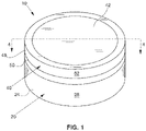
- Figs. 1-3 illustrate one container 10 in accordance with the present disclosure.
- the container 10 may be formed by an open-ended body 20 and a lid 40.
- the lid 40 is removable from the body 20 to provide access to a product held within the container 10.
- the body 20 has a bottom wall 22 (see Fig. 2 ), which, in some instances, may be substantially planar, and a peripheral flange 24 depending from the bottom wall 22 which, in some instances, may be cylindrical as shown.
- the peripheral flange 24 may define a peripheral portion of the container 10 such that the peripheral flange includes an outer peripheral surface 28.
- the bottom wall 22 and the peripheral flange 24 cooperate to define an internal storage compartment 26 for storage of a plurality of units of a product.
- an upper portion 30 of the peripheral flange 24 may define a lip 32 in such a manner that the upper portion 30 the peripheral flange has a neck region 34 of reduced diameter (as compared to the diameter of the remainder of the outer surface of the peripheral flange).
- a projection 39 may extend from the neck region 34 and be provided about the periphery of the upper portion 30 of the peripheral flange 24 to provide an interference fit with the lid 40.
- the lid 40 may be provided for enclosing the units of product within the internal storage compartment 26.
- the lid 40 is typically removably secured to the body 20 by a snap-fit or an interference fit.
- the lid 40 has a laterally-extending wall 42, which, in some instances, may be substantially planar.
- the wall 42 has opposing outer and inner surfaces 44, 46 and defines a periphery.
- the wall 42 has a central axis C extending perpendicularly to the outer and inner surfaces 44, 46.
- a sidewall 48 extends from the inner surface and about the periphery of the wall. In one embodiment, the sidewall 48 extends parallel to the central axis C. In the illustrated example, the sidewall 48 is cylindrical.
- the sidewall 48 of the lid 40 may be received over the peripheral flange 24 of the body 20 so as to form an enclosure therebetween.
- an edge 50 of the sidewall 48 may interact with a surface 36 of the lip 32 to form a stop when the lid 40 is received upon the body 20.
- the edge 50 of the lid 40 which is typically substantially planar, will abut the surface 36 of the lip 32, which is also typically substantially planar, when the lid 40 is fully seated upon the body 20.
- a cylindrical exterior surface 52 of the lid 40 may have the same approximate size or diameter as the peripheral flange 24 of the body 20 such that the lid and body form a smooth exterior surface when the lid is placed over the neck region 34 of the peripheral flange and fully seated upon the body.
- the exterior surface 52 of the lid 40 may have a size or diameter that is larger than the peripheral flange 24 of the body 20 so the user may access the edge 50 of the lid 40 for removing the lid from the body.
- the material for constructing the body 20 can vary.
- Example materials include metal, wood, and synthetic plastic materials.
- the body 20 is formed from a polymeric material. Polymeric materials that can be extruded and/or molded into desired shapes are typically utilized, such as polypropylene, polyethylene, polystyrene, polyamide, and the like.
- Fig. 3 shows an interior perspective view of the lid 40.
- a rib structure 60 projects from the inner surface 46 of the laterally extending wall 42.
- the rib structure 60 may be integrally formed with the wall 42.
- the rib structure 60 may be formed by a plurality of rib segments 62 arranged in spaced relation around the periphery of the wall 42 (e.g., positioned circumferentially about the wall 42 where the lid 40 is cylindrical). Any number of rib segments 62 greater than one may be provided in accordance with the present disclosure (e.g., about 2 to about 20 rib segments or about 5 to about 15 rib segments).
- the rib segments 62 are separated from one another by a vent channel 64.
- each pair of adjacent rib segments 62 may form a vent channel 64 therebetween that allows venting from the interior of the container 10 to the atmosphere exterior of the container.
- the sidewall 48 of the lid 40 may include a radially inward extending detent 68 extending circumferentially around the central axis C of the lid 40.
- the detent 68 may be configured to engage with the projection 39 of the body 20 to assist with retention of the lid 40 on the body 20.
- the laterally extending wall 42, sidewall 48, and rib structure 60 of the lid 40 are integrally formed into a base 70 from polymeric materials.
- Example polymeric materials that can be formed into the base 70 are materials that can be extruded and/or molded into the desired shapes, such as polypropylene, polyethylene, polystyrene, polyamide, and the like.
- the shape of the exterior surface 52 of the lid 40 of the disclosure can vary. Therefore, although the container 10 is represented as a substantially cylindrical "puck" shape, the container 10 may be configured with alternative peripheral shapes, such as a square, a rectangle, various other regular or irregular polygonal shapes, an oval, or other suitable shapes. Further, the sides or edges of the containers of the disclosure could be flattened, rounded, or beveled, and the various surfaces or edges of the container exterior could be concave or convex unless expressly stated otherwise in claimed embodiments. Further, the opposing sides, ends, or edges of the container can be parallel or non-parallel such that the container becomes narrower in one or more dimensions.
- the dimensions of the containers described herein can vary without departing from the disclosure. However, in some examples, the containers of the disclosure can be described as having a cylindrical size suitable for handheld manipulation and operation.
- Example dimensions for such handheld cylindrical embodiments include diameters in the range of about 50 mm to about 100 mm, and more typically about 60 mm to about 80 mm.
- Example wall thicknesses include the range of about 0.5 mm to about 1.5 mm, and more typically about 0.8 mm to about 1.4 mm.
- Example depths for handheld container embodiments of the present disclosure range from about 5 mm to about 50 mm, more typically about 8 mm to about 30 mm, and most often about 15 mm to about 25 mm.
- the number of solid product units stored in the containers of the disclosure can also vary, depending on the size of the container and the size of the product units. Typically, the number of stored product units will vary from about 5 to about 100, more typically about 10 to about 50, and most often about 15 to about 30.
- the polymeric base 70 of the lid 40 which includes at least the laterally extending wall 42 and the sidewall 48, supports a metallic cladding 80 engaged with the wall 42 so as to extend laterally across the outer surface 44 of the wall.
- the cladding 80 comprises a metallic material, such as tin, brass, bronze, nickel, aluminum, steel, or tin coated steel plate.
- the cladding 80 may be formed from a single sheet of metal via punching, stamping, trimming, forming the sheet of metal and/or via other operations.
- Providing a metallic cladding 80 engaged with a polymeric base 70 may be advantageous in that the illustrated combination may provide an aesthetically appealing appearance by using a metallic material to form the prominent merchandizing portion of the container 10, while also allowing the remainder of the base 70 and container to be less expensively produced using, for example, an injection molding process.
- Advantageous examples of the present disclosure utilize an adhesive to bond the cladding 80 to the polymeric base 70.
- the metallic cladding 80 can be bonded to the polymeric base 70 during a molding operation.
- insert molding techniques could be used to affix the cladding 80 to the base 70 during an injection molding process used to create the final shape of the base portion of the lid structure.
- Such processes typically involve placing an insert, in this case a cladding material, within a mold prior to injection of a polymeric material into the mold. As the final polymeric structure is formed, structural integration with the insert takes place.
- the cladding 80 may provide a merchandizing portion of the lid 40 by being embossed with product branding or other aesthetically pleasing or informative labeling 82.
- the labeling 82 may additionally or alternatively be provided integrally with the cladding 80 through other processes such as casting, printing (e.g., infusing dyes into the surface of the cladding), etching (e.g., via various laser, chemical, and/or other suitable etching techniques), or other suitable process for adding text, graphics, and/or other ornamentation to a metal surface.
- the labeling 82 may alternatively be separately attached to the cladding, such as by use of a labeling sticker.
- the cladding 80 may be substantially planar.
- the cladding 80 comprises a metallic sheet having a thickness between about 0.1 mm and about 0.5 mm.
- the metallic sheet has a thickness between about 0.1 mm and about 0.2 mm.
- the cladding 80 may be a foil.
- the cladding 80 may be a coating applied to the base 70.
- the cladding 80 may comprise a film applied to the base 70.
- the cladding 80 may be engaged with the outer surface 44 of the wall 42 using an adhesive layer 84 disposed therebetween.
- the adhesive layer 84 may have a thickness of between about 0.01 mm and about 0.5 mm.
- the adhesive layer 84 is a coating applied to a surface of the cladding 80 in a step separate from joining the cladding to the base 70.
- the coating is a solvent-based polyolefin dispersion heat-seal coating, which may be a heat-actuated adhesive coating.
- a suitable coating may be sold under the tradename MORPRIME TM by the Dow Chemical Company. Acrylic, aqueous heat seal coatings available from Roymal Inc. may also be suitable. Aqueous emulsion waterborne heat-seal coatings available from Mico-Corp may also be suitable.
- the coatings may be applied to the cladding with known processes such as printing, gravure, rotogravure, flexographic, and offset.
- a heat-seal coating or heat-actuated adhesive coating as the adhesive layer 84 allows the cladding 80 to be pre-coated with the adhesive layer for later attachment to the base 70.
- the coating particularly a heat-seal coating, can then be activated by heat to facilitate a bond between the metallic cladding 80 and the polymeric base 70.
- the coating Prior to being heated, the coating may not be tacky, facilitating use of a cladding 80 with an adhesive layer coating in high-speed production lines.
- heat for activing the adhesive layer 84 coating may be created using induction heating.
- Adherence between the cladding 80 with the adhesive layer 84 and the base 70 may be generated using the same or similar methodology as employed within known induction sealing or heat sealing machines.
- Such machines including production line machines, are available from companies such as Relco UK, Selig Sealing Products, Inc., and ME.RO S.p.A, and Enercon Industries.
- Induction sealers would be used to create an electromagnetic field in the presence of the metallic cladding 80. Exposure of the cladding 80 and heat-actuated adhesive layer 84 to the magnetic field induces eddy currents within the cladding that causes the cladding to quickly generate heat therein, wherein the heat would be conducted to the adhesive layer 84.
- Typical induction sealers include a power source, a coil for generating a magnetic field, and a cooling system.
- the lid 40 may have a maximum height along a direction parallel with the central axis C of less than about 8.89 mm (0.35 inches). In another embodiment, the maximum height of the lid 40 may be less than about 7.62 mm (0.30 inches) and may be less than about 7.112 mm (0.28 inches). The height includes both the body 70 and the cladding 80. The same suitable dimensions may apply to the further examples discussed below.
- Figs. 5A and 5B show a lid 40a according to a second example of the present disclosure.
- the interior of the lid 40a may be substantially similar to the lid 40 discussed above, and as a result, the lid 40a may be configured to engage the body 20 in the same manner as discussed above.
- the lid 40a illustrates the cladding 80a extending across substantially the entirety of the top surface 44 of the wall 42. Particularly, as illustrated, the top surface 44 of the polymeric base 70 is substantially entirely hidden from view by the cladding 80a.
- the cladding 80a may include an adhesive layer 84, coated thereon in advance, that may be active by heat through an induction bonding machine as discussed hereinabove.
- Figs. 6A and 6B show a lid 40b according to a third example of the present disclosure.
- the interior of the lid 40b may be substantially similar to the lid 40 discussed above, and as a result, the lid 40b may be configured to engage the body 20 in the same manner as discussed above.
- the cladding 80b is engaged with the wall 42 using an adhesive layer 84, such as the induction bonded, heat seal coating layer described above.
- the wall 48 of the base 70b may also include a groove 49 recessed in the exterior surface 52.
- the groove 49 may be configured to receive the peripheral edge 86 of the cladding 80b.
- the peripheral edge 86 may be bent or otherwise angled to reside in the groove 49.
- the depth of the groove 49 in the radial direction toward axis C may be selected such that the exterior surface 52 is flush with the surface of the cladding 80b when the peripheral edge 86 is disposed within the groove 49.
- the groove 49 is deeper than the thickness of the cladding 80b such that the cladding is recessed relative to the exterior surface 52.
- Figs. 7A and 7B show a lid 40c according to an embodiment of the present invention.
- the interior of the lid 40c may be substantially similar to the lid 40 discussed above, and as a result, the lid 40c may be configured to engage the body 20 in the same manner as discussed above.
- the cladding 80c is engaged with the wall 42 using an adhesive layer 84, such as the induction bonded, heat seal coating layer described above.
- the wall 48 of the base 70b may also include a groove 49 recessed in the exterior surface 52.
- the groove 49 may be configured to receive the peripheral edge 86 of the cladding 80c.
- the peripheral edge 86 may be bent or otherwise angled, such as by stamping, to reside in the groove 49.
- the cladding 80c may be less susceptible to peeling away from the base 70b.
- the depth of the groove 49 in the radial direction toward axis C may be selected such that the exterior surface 52 is flush with the surface of the cladding 80c when the peripheral edge 86 is disposed within the groove 49.
- the groove 49 is deeper than the thickness of the cladding 80c such that the cladding is recessed relative to the exterior surface 52.
- the cladding 80c may be pre-formed, such as by stamping, with a peripheral ridge 87.
- the peripheral ridge 87 may assist with the rigidity of the cladding 80c and help minimize warping near the center of the cladding.
- the peripheral ridge 87 may provide a tactile feature that assist the user with at least one of adding or removing the lid 40c from the body 20 ( FIG. 1 ).
- the material and thickness of the cladding 80c may be selected such that the peripheral ridge 87 is self-supporting and would remain raised under force conditions typical to opening or closing the container 10 and force conditions typically encountered during transportation of the container. By being self-supporting, the peripheral ridge 87 of the cladding 80c may avoid the use of an upward projection formed from the polymeric material of the base 70b.
- the containers 10 of the disclosure can be sealed with a circumferential label or wrapper of a pervious or impervious material.
- the label or wrapping material useful in accordance with the present disclosure can vary. Typically, the selection of the packaging label or wrapper is dependent upon factors such as aesthetics, desired barrier properties (e.g., so as to provide protection from exposure to oxygen, or so as to provide protection from loss of moisture), or the like.
Landscapes
- Engineering & Computer Science (AREA)
- Mechanical Engineering (AREA)
- Packages (AREA)
- Closures For Containers (AREA)
Claims (12)
- Couvercle (40, 40c) destiné à un récipient (10) permettant de stocker un produit de tabac sans fumée, le couvercle (40, 40c) comprenant :une paroi s'étendant latéralement (42) ayant des première et seconde surfaces opposées (44, 46) et définissant une périphérie, la paroi s'étendant latéralement (42) ayant un axe central (C) qui s'étend perpendiculairement aux première et seconde surfaces (44, 46) ;une paroi latérale (48) s'étendant à partir de la seconde surface (46) autour de la périphérie de la paroi s'étendant latéralement (42), la paroi s'étendant latéralement (42) et la paroi latérale (48) étant constituées d'un matériau polymérique ;un revêtement métallique (80, 80c) comprenant une feuille métallique, ladite feuille métallique comprenant une arête surélevée (87) adjacente à une périphérie de celle-ci, le revêtement métallique (80, 80c) étant en prise avec la paroi s'étendant latéralement (42) de manière à s'étendre latéralement sur la première surface (44), dans lequel la paroi latérale (48) comporte une rainure (49) recevant un bord périphérique (86) du revêtement métallique (80c ;ledit couvercle étant caractérisé en ce que :
ladite rainure (49) est encastrée dans une surface extérieure de ladite paroi latérale (48). - Couvercle (40, 40c) selon la revendication 1, dans lequel le bord périphérique (86) du revêtement (80, 80c) est incliné pour résider dans la rainure (49).
- Couvercle (40, 40c) selon la revendication 1, dans lequel la rainure (49) est encastrée radialement vers l'intérieur en direction de l'axe central (C) de la paroi s'étendant latéralement (42) à partir de la surface extérieure de la paroi latérale selon une distance supérieure ou égale à une épaisseur du revêtement ; et éventuellement :dans lequel la feuille métallique est gaufrée ; et éventuellementdans lequel l'arête surélevée (87) est autoportante ; et éventuellementdans lequel la feuille métallique a une épaisseur comprise entre environ 0,1 mm et environ 0,5 mm ; et éventuellementdans lequel la paroi latérale (48) s'étend de manière sensiblement parallèle à l'axe central (C) de la paroi s'étendant latéralement (42).
- Couvercle (40, 40c) selon la revendication 1, comprenant en outre une structure de nervures (60) faisant saillie à partir de la seconde surface (46) de la paroi s'étendant latéralement (42), la structure de nervures (60) comprenant une pluralité de segments de nervure (62) disposés en relation espacée à proximité de la périphérie de la paroi s'étendant latéralement (42) .
- Couvercle (40, 40c) selon la revendication 1, dans lequel la paroi latérale (48) comprend en outre un cran d'extension radialement vers l'intérieur (68) s'étendant circonférentiellement autour de l'axe central (C) de la paroi s'étendant latéralement (42).
- Couvercle (40, 40c) selon la revendication 1, dans lequel une couche adhésive (84) est placée entre le revêtement (80, 80c) et la première surface (44) ; et éventuellementdans lequel la couche adhésive (84) est un revêtement qui peut être pré-appliqué sur le revêtement (80, 80c) ; et éventuellementdans lequel la couche adhésive (84) peut être activée par la chaleur pour créer une adhérence entre le revêtement (80, 80c) et la paroi (42) lorsque le revêtement est soumis à un champ magnétique ; et éventuellementdans lequel la couche adhésive (84) comprend un adhésif thermocollant.
- Procédé de fabrication d'un couvercle (40, 40c) destiné à un récipient (10) permettant de stocker un produit de tabac sans fumée, le procédé comprenant :la réception d'une structure de couvercle (40, 40c) comprenant une paroi s'étendant latéralement (42) ayant des première et seconde surfaces opposées (44, 46) et définissant une périphérie, la paroi s'étendant latéralement (42) ayant un axe central (C) qui s'étend perpendiculairement aux première et seconde surfaces (44, 46), et une paroi latérale (48) qui s'étend à partir de la seconde surface (46) autour de la périphérie de la paroi s'étendant latéralement (42), dans lequel ladite paroi latérale (48) comporte une rainure (49) encastrée dans une surface extérieure de celui-ci, la paroi s'étendant latéralement (42) et la paroi latérale (48) étant constituées d'un matériau polymère ;la réception d'un revêtement métallique (80, 80c), dans lequel le revêtement métallique (80, 80c) comprend une feuille métallique, ladite feuille métallique comprenant une arête surélevée (87) adjacente à une périphérie de celle-ci ;la disposition du revêtement métallique (80, 80c) adjacente à la première surface (44) de la paroi s'étendant latéralement (42) de sorte que le revêtement métallique (80, 80c) s'étend latéralement sur la première surface (44) avec un adhésif thermocollant (84) placé entre le revêtement métallique (80, 80c) et la première surface (44) ;la disposition d'un bord périphérique (86) du revêtement métallique (80, 80c) dans la rainure (49) ;l'exposition du revêtement métallique (80, 80c) et de l'adhésif thermocollant (84) à la chaleur afin d'activer l'adhésif thermocollant pour coller le revêtement métallique (80, 80c) à la première surface (44).
- Procédé selon la revendication 7, comprenant en outre le gaufrage du revêtement métallique (80, 80c).
- Procédé selon la revendication 7, comprenant en outre l'étape de revêtement de l'adhésif thermocollant (84) sur soit au moins une partie d'une surface du revêtement métallique (80, 80c), soit au moins une partie de la première surface (44) de la paroi s'étendant latéralement (42) de la structure de couvercle (40, 40c) avant ladite étape de disposition.
- Procédé selon la revendication 9, dans lequel l'étape de revêtement comprend l'impression de l'adhésif thermocollant (84) sur au moins une partie d'une surface du revêtement métallique (80, 80c).
- Procédé selon la revendication 7, dans lequel soit le revêtement métallique (80, 80c), soit la structure de couvercle (40, 40c) est reçue prétraitée avec l'adhésif thermocollant (84) .
- Procédé selon la revendication 7, dans lequel l'exposition à la chaleur du revêtement métallique (80, 80c) et de l'adhésif thermocollant (84) consiste à utiliser une scelleuse par induction.
Applications Claiming Priority (3)
| Application Number | Priority Date | Filing Date | Title |
|---|---|---|---|
| US201862657327P | 2018-04-13 | 2018-04-13 | |
| US201862737496P | 2018-09-27 | 2018-09-27 | |
| PCT/IB2019/053050 WO2019198055A2 (fr) | 2018-04-13 | 2019-04-12 | Couvercle pour récipient pour produits de tabac sans fumée |
Publications (2)
| Publication Number | Publication Date |
|---|---|
| EP3774570A2 EP3774570A2 (fr) | 2021-02-17 |
| EP3774570B1 true EP3774570B1 (fr) | 2022-04-27 |
Family
ID=66647435
Family Applications (1)
| Application Number | Title | Priority Date | Filing Date |
|---|---|---|---|
| EP19726486.4A Active EP3774570B1 (fr) | 2018-04-13 | 2019-04-12 | Couvercle pour un récipient pour produits de tabac sans fumée et procédé de fabrication d'un tel couvercle |
Country Status (4)
| Country | Link |
|---|---|
| US (1) | US20200277110A1 (fr) |
| EP (1) | EP3774570B1 (fr) |
| DK (1) | DK3774570T3 (fr) |
| WO (1) | WO2019198055A2 (fr) |
Families Citing this family (3)
| Publication number | Priority date | Publication date | Assignee | Title |
|---|---|---|---|---|
| US20220135296A1 (en) * | 2020-10-29 | 2022-05-05 | Terence H. Wendelken | Removable magnetic lid for a container |
| WO2024074988A1 (fr) | 2022-10-04 | 2024-04-11 | R. J. Reynolds Tobacco Company | Agencement empilable de contenants de produit et procédé d'empilement associé |
| US11975898B1 (en) | 2022-10-12 | 2024-05-07 | Altria Client Services Llc | Child-resistant lid for a container |
Family Cites Families (61)
| Publication number | Priority date | Publication date | Assignee | Title |
|---|---|---|---|---|
| US1376586A (en) | 1918-04-06 | 1921-05-03 | Schwartz Francis | Tobacco-tablet |
| GB943117A (en) * | 1961-01-10 | 1963-11-27 | Metal Containers Ltd | Improvements in or relating to containers and closures therefor |
| US3368567A (en) | 1965-03-23 | 1968-02-13 | Morton Pharmaceuticals Inc | Method of producing a tablet containing a tobacco concentrate |
| US3696917A (en) | 1970-09-10 | 1972-10-10 | Elaine G Levi | Tobacco pouch closure |
| US3782575A (en) * | 1972-03-06 | 1974-01-01 | T Braun | Safety closure |
| CA1095459A (fr) * | 1976-06-07 | 1981-02-10 | Donald H. Ellerbrock | Traduction non-disponible |
| US4098421A (en) | 1977-06-24 | 1978-07-04 | J. L. Clark Manufacturing Co. | Container for snuff or the like |
| US4190170A (en) | 1979-01-15 | 1980-02-26 | United States Tobacco Company | Snuff can and the like |
| US4528993A (en) | 1982-08-20 | 1985-07-16 | R. J. Reynolds Tobacco Company | Process for producing moist snuff |
| US4513756A (en) | 1983-04-28 | 1985-04-30 | The Pinkerton Tobacco Company | Process of making tobacco pellets |
| DK149920C (da) | 1983-09-20 | 1987-05-18 | Krueger S Eftf A S Hermann | Fremgangsmaade ved portionering af snus og emballering af de enkelte snusportioner |
| US5092352A (en) | 1983-12-14 | 1992-03-03 | American Brands, Inc. | Chewing tobacco product |
| SE450566B (sv) | 1983-12-14 | 1987-07-06 | Svenska Tobaks Ab | Anordning for att portionsforpacka snus |
| US4624269A (en) | 1984-09-17 | 1986-11-25 | The Pinkerton Tobacco Company | Chewable tobacco based product |
| US4606357A (en) | 1984-11-19 | 1986-08-19 | Dusek Russell L | Tobacco composition |
| US4975270A (en) | 1987-04-21 | 1990-12-04 | Nabisco Brands, Inc. | Elastomer encased active ingredients |
| US4802498A (en) | 1987-07-02 | 1989-02-07 | Warren Ogren | Resin-based chewing tobacco |
| US4821749A (en) | 1988-01-22 | 1989-04-18 | R. J. Reynolds Tobacco Company | Extruded tobacco materials |
| US4987907A (en) | 1988-06-29 | 1991-01-29 | Helme Tobacco Company | Chewing tobacco composition and process for producing same |
| US4991599A (en) | 1989-12-20 | 1991-02-12 | Tibbetts Hubert M | Fiberless tobacco product for smoking and chewing |
| US5167244A (en) | 1990-01-19 | 1992-12-01 | Kjerstad Randy E | Tobacco substitute |
| US5346734A (en) | 1993-04-16 | 1994-09-13 | Bethanie K. Wydick | Perforated latex oral pouch for loose snuff |
| US5387416A (en) | 1993-07-23 | 1995-02-07 | R. J. Reynolds Tobacco Company | Tobacco composition |
| US6162516A (en) | 1995-10-11 | 2000-12-19 | Derr; Dedric M. | System and method for protecting oral tissues from smokeless tobacco |
| US20040020503A1 (en) | 2001-05-01 | 2004-02-05 | Williams Jonnie R. | Smokeless tobacco product |
| US6668839B2 (en) | 2001-05-01 | 2003-12-30 | Jonnie R. Williams | Smokeless tobacco product |
| HUP0400094A3 (en) | 2001-05-01 | 2005-03-29 | Regent Court Technologies Llc | Smokeless tobacco product |
| US7032601B2 (en) | 2001-09-28 | 2006-04-25 | U.S. Smokeless Tobacco Company | Encapsulated materials |
| US6953040B2 (en) | 2001-09-28 | 2005-10-11 | U.S. Smokeless Tobacco Company | Tobacco mint plant material product |
| DK1458252T3 (da) | 2001-12-21 | 2008-05-13 | Galenica Ab | Tobak og/eller tobak i kombination med tobakssubstitutkomposition til anvendelse som snus i den orale kavitet |
| US20040118422A1 (en) | 2002-12-19 | 2004-06-24 | Swedish Match North Europe Ab | Tobacco dough and a method for its manufacture |
| SE0301244D0 (sv) | 2003-04-29 | 2003-04-29 | Swedish Match North Europe Ab | Smokeless tobacco product user package |
| US20040217024A1 (en) | 2003-04-29 | 2004-11-04 | Jan Arnarp | Smokeless tobacco product user package |
| SE527350C8 (sv) | 2003-08-18 | 2006-03-21 | Gallaher Snus Ab | Lock till snusdosa |
| US7901512B2 (en) | 2003-11-03 | 2011-03-08 | U.S. Smokeless Tobacco Company | Flavored smokeless tobacco and methods of making |
| US8627828B2 (en) | 2003-11-07 | 2014-01-14 | U.S. Smokeless Tobacco Company Llc | Tobacco compositions |
| EP1691631A4 (fr) | 2003-11-07 | 2012-09-05 | Us Smokeless Tobacco Co | Compositions a base de tabac |
| EP1729602A1 (fr) | 2003-12-22 | 2006-12-13 | U.S. Smokeless Tobacco Company | Procede de traitement pour compositions de tabac ou de tabac a priser |
| DE602005015854D1 (de) | 2004-07-02 | 2009-09-17 | Radi Medical Biodegradable Ab | Rauchloses tabakprodukt |
| US20060060480A1 (en) | 2004-09-21 | 2006-03-23 | Budd James P | Smokeless tobacco container with improved cover |
| US7537110B2 (en) | 2005-06-02 | 2009-05-26 | Philip Morris Usa Inc. | Container for consumer article |
| US7861728B2 (en) | 2006-02-10 | 2011-01-04 | R.J. Reynolds Tobacco Company | Smokeless tobacco composition having an outer and inner pouch |
| US20070062549A1 (en) | 2005-09-22 | 2007-03-22 | Holton Darrell E Jr | Smokeless tobacco composition |
| US20070130811A1 (en) | 2005-12-09 | 2007-06-14 | U.S. Smokeless Tobacco Company | Tamper evident label |
| US7819124B2 (en) | 2006-01-31 | 2010-10-26 | U.S. Smokeless Tobacco Company | Tobacco articles and methods |
| US7810507B2 (en) | 2006-02-10 | 2010-10-12 | R. J. Reynolds Tobacco Company | Smokeless tobacco composition |
| SE529886C2 (sv) | 2006-04-28 | 2007-12-18 | Swedish Match North Europe Ab | En ny metod för framställning av en fuktsnuskomposition som inte innehåller tobak |
| US20080029116A1 (en) | 2006-08-01 | 2008-02-07 | John Howard Robinson | Smokeless tobacco |
| US20080173317A1 (en) | 2006-08-01 | 2008-07-24 | John Howard Robinson | Smokeless tobacco |
| US20080029117A1 (en) | 2006-08-01 | 2008-02-07 | John-Paul Mua | Smokeless Tobacco |
| SE530736C2 (sv) | 2006-11-28 | 2008-08-26 | Snusmumrik Hb | Snusdosa |
| BRPI0807783A2 (pt) | 2007-02-23 | 2014-06-24 | Us Smokeless Tobacco Co | Composição de tabaco sem fumaça, métodos para produzir uma variedade de planta e para preparar tabaco tendo amargor reduzido, planta de tabaco, variedade de planta, e, tabaco curado. |
| US8940344B2 (en) | 2007-06-08 | 2015-01-27 | Philip Morris Usa Inc. | Capsule clusters for oral consumption |
| AR068155A1 (es) * | 2007-08-31 | 2009-11-04 | Brasilata Embalagens Metalicas | Tapa compuesta para recipientes |
| US8336557B2 (en) | 2007-11-28 | 2012-12-25 | Philip Morris Usa Inc. | Smokeless compressed tobacco product for oral consumption |
| US7798319B1 (en) | 2008-03-11 | 2010-09-21 | U.S. Smokeless Tobacco Company | Container device for tobacco articles |
| US20090289074A1 (en) * | 2008-05-23 | 2009-11-26 | Helen Of Troy | Cotainer lid |
| US20100043812A1 (en) * | 2008-08-22 | 2010-02-25 | Benjamin James Yount | Can for making quiet pack of smokeless tobacco |
| US9155772B2 (en) | 2008-12-08 | 2015-10-13 | Philip Morris Usa Inc. | Soft, chewable and orally dissolvable and/or disintegrable products |
| CA2761737A1 (fr) | 2009-05-11 | 2010-11-18 | U.S. Smokeless Tobacco Company Llc | Procede et dispositif pour aromatiser du tabac sans fumee |
| US8910781B2 (en) | 2013-01-11 | 2014-12-16 | R.J. Reynolds Tobacco Company | Container for smokeless tobacco products and related packaged product assembly and method |
-
2019
- 2019-04-12 EP EP19726486.4A patent/EP3774570B1/fr active Active
- 2019-04-12 DK DK19726486.4T patent/DK3774570T3/da active
- 2019-04-12 WO PCT/IB2019/053050 patent/WO2019198055A2/fr active Application Filing
-
2020
- 2020-05-15 US US16/875,732 patent/US20200277110A1/en not_active Abandoned
Also Published As
| Publication number | Publication date |
|---|---|
| US20200277110A1 (en) | 2020-09-03 |
| DK3774570T3 (da) | 2022-05-23 |
| WO2019198055A2 (fr) | 2019-10-17 |
| EP3774570A2 (fr) | 2021-02-17 |
| WO2019198055A3 (fr) | 2019-11-14 |
Similar Documents
| Publication | Publication Date | Title |
|---|---|---|
| EP2670681B1 (fr) | Contenant pour produits de tabac sans fumee | |
| US10701968B2 (en) | Package for a tobacco-containing material with a valve assembly and related packaging method | |
| US9717272B2 (en) | Container for smokeless tobacco product | |
| EP3774570B1 (fr) | Couvercle pour un récipient pour produits de tabac sans fumée et procédé de fabrication d'un tel couvercle | |
| US20210235751A1 (en) | Package for a tobacco-containing material and related packaging method | |
| EP3755641B1 (fr) | Contenant destiné à des produits de tabac sans fumée | |
| US20220000175A1 (en) | Container for smokeless tobacco products comprising a pulp material and related packaged product assembly and method | |
| EP2337745B1 (fr) | Recipient pour contenir de petits articles | |
| US20150320113A1 (en) | Containers, Convertible Packaging Devices, Packaged Product Assemblies, and Product Display Methods for Smokeless Tobacco Products | |
| US20150321787A1 (en) | Containers, Convertible Packaging Devices, Packaged Product Assemblies, and Product Display Methods for Smokeless Tobacco Products | |
| EA010515B1 (ru) | Обернутая емкость с этикеткой | |
| RU2772155C2 (ru) | Контейнер для бездымных табачных продуктов |
Legal Events
| Date | Code | Title | Description |
|---|---|---|---|
| STAA | Information on the status of an ep patent application or granted ep patent |
Free format text: STATUS: UNKNOWN |
|
| STAA | Information on the status of an ep patent application or granted ep patent |
Free format text: STATUS: THE INTERNATIONAL PUBLICATION HAS BEEN MADE |
|
| PUAI | Public reference made under article 153(3) epc to a published international application that has entered the european phase |
Free format text: ORIGINAL CODE: 0009012 |
|
| STAA | Information on the status of an ep patent application or granted ep patent |
Free format text: STATUS: REQUEST FOR EXAMINATION WAS MADE |
|
| 17P | Request for examination filed |
Effective date: 20201014 |
|
| AK | Designated contracting states |
Kind code of ref document: A2 Designated state(s): AL AT BE BG CH CY CZ DE DK EE ES FI FR GB GR HR HU IE IS IT LI LT LU LV MC MK MT NL NO PL PT RO RS SE SI SK SM TR |
|
| AX | Request for extension of the european patent |
Extension state: BA ME |
|
| DAV | Request for validation of the european patent (deleted) | ||
| DAX | Request for extension of the european patent (deleted) | ||
| GRAP | Despatch of communication of intention to grant a patent |
Free format text: ORIGINAL CODE: EPIDOSNIGR1 |
|
| STAA | Information on the status of an ep patent application or granted ep patent |
Free format text: STATUS: GRANT OF PATENT IS INTENDED |
|
| INTG | Intention to grant announced |
Effective date: 20211112 |
|
| GRAS | Grant fee paid |
Free format text: ORIGINAL CODE: EPIDOSNIGR3 |
|
| GRAA | (expected) grant |
Free format text: ORIGINAL CODE: 0009210 |
|
| STAA | Information on the status of an ep patent application or granted ep patent |
Free format text: STATUS: THE PATENT HAS BEEN GRANTED |
|
| AK | Designated contracting states |
Kind code of ref document: B1 Designated state(s): AL AT BE BG CH CY CZ DE DK EE ES FI FR GB GR HR HU IE IS IT LI LT LU LV MC MK MT NL NO PL PT RO RS SE SI SK SM TR |
|
| REG | Reference to a national code |
Ref country code: GB Ref legal event code: FG4D |
|
| REG | Reference to a national code |
Ref country code: CH Ref legal event code: EP |
|
| REG | Reference to a national code |
Ref country code: DE Ref legal event code: R096 Ref document number: 602019014191 Country of ref document: DE |
|
| REG | Reference to a national code |
Ref country code: AT Ref legal event code: REF Ref document number: 1486797 Country of ref document: AT Kind code of ref document: T Effective date: 20220515 |
|
| REG | Reference to a national code |
Ref country code: DK Ref legal event code: T3 Effective date: 20220518 |
|
| REG | Reference to a national code |
Ref country code: IE Ref legal event code: FG4D |
|
| REG | Reference to a national code |
Ref country code: SE Ref legal event code: TRGR |
|
| REG | Reference to a national code |
Ref country code: NO Ref legal event code: T2 Effective date: 20220427 |
|
| REG | Reference to a national code |
Ref country code: LT Ref legal event code: MG9D |
|
| REG | Reference to a national code |
Ref country code: NL Ref legal event code: MP Effective date: 20220427 |
|
| REG | Reference to a national code |
Ref country code: AT Ref legal event code: MK05 Ref document number: 1486797 Country of ref document: AT Kind code of ref document: T Effective date: 20220427 |
|
| PG25 | Lapsed in a contracting state [announced via postgrant information from national office to epo] |
Ref country code: NL Free format text: LAPSE BECAUSE OF FAILURE TO SUBMIT A TRANSLATION OF THE DESCRIPTION OR TO PAY THE FEE WITHIN THE PRESCRIBED TIME-LIMIT Effective date: 20220427 |
|
| PG25 | Lapsed in a contracting state [announced via postgrant information from national office to epo] |
Ref country code: PT Free format text: LAPSE BECAUSE OF FAILURE TO SUBMIT A TRANSLATION OF THE DESCRIPTION OR TO PAY THE FEE WITHIN THE PRESCRIBED TIME-LIMIT Effective date: 20220829 Ref country code: LT Free format text: LAPSE BECAUSE OF FAILURE TO SUBMIT A TRANSLATION OF THE DESCRIPTION OR TO PAY THE FEE WITHIN THE PRESCRIBED TIME-LIMIT Effective date: 20220427 Ref country code: HR Free format text: LAPSE BECAUSE OF FAILURE TO SUBMIT A TRANSLATION OF THE DESCRIPTION OR TO PAY THE FEE WITHIN THE PRESCRIBED TIME-LIMIT Effective date: 20220427 Ref country code: GR Free format text: LAPSE BECAUSE OF FAILURE TO SUBMIT A TRANSLATION OF THE DESCRIPTION OR TO PAY THE FEE WITHIN THE PRESCRIBED TIME-LIMIT Effective date: 20220728 Ref country code: FI Free format text: LAPSE BECAUSE OF FAILURE TO SUBMIT A TRANSLATION OF THE DESCRIPTION OR TO PAY THE FEE WITHIN THE PRESCRIBED TIME-LIMIT Effective date: 20220427 Ref country code: BG Free format text: LAPSE BECAUSE OF FAILURE TO SUBMIT A TRANSLATION OF THE DESCRIPTION OR TO PAY THE FEE WITHIN THE PRESCRIBED TIME-LIMIT Effective date: 20220727 Ref country code: AT Free format text: LAPSE BECAUSE OF FAILURE TO SUBMIT A TRANSLATION OF THE DESCRIPTION OR TO PAY THE FEE WITHIN THE PRESCRIBED TIME-LIMIT Effective date: 20220427 |
|
| PG25 | Lapsed in a contracting state [announced via postgrant information from national office to epo] |
Ref country code: RS Free format text: LAPSE BECAUSE OF FAILURE TO SUBMIT A TRANSLATION OF THE DESCRIPTION OR TO PAY THE FEE WITHIN THE PRESCRIBED TIME-LIMIT Effective date: 20220427 Ref country code: PL Free format text: LAPSE BECAUSE OF FAILURE TO SUBMIT A TRANSLATION OF THE DESCRIPTION OR TO PAY THE FEE WITHIN THE PRESCRIBED TIME-LIMIT Effective date: 20220427 Ref country code: LV Free format text: LAPSE BECAUSE OF FAILURE TO SUBMIT A TRANSLATION OF THE DESCRIPTION OR TO PAY THE FEE WITHIN THE PRESCRIBED TIME-LIMIT Effective date: 20220427 Ref country code: IS Free format text: LAPSE BECAUSE OF FAILURE TO SUBMIT A TRANSLATION OF THE DESCRIPTION OR TO PAY THE FEE WITHIN THE PRESCRIBED TIME-LIMIT Effective date: 20220827 |
|
| REG | Reference to a national code |
Ref country code: DE Ref legal event code: R097 Ref document number: 602019014191 Country of ref document: DE |
|
| PG25 | Lapsed in a contracting state [announced via postgrant information from national office to epo] |
Ref country code: SM Free format text: LAPSE BECAUSE OF FAILURE TO SUBMIT A TRANSLATION OF THE DESCRIPTION OR TO PAY THE FEE WITHIN THE PRESCRIBED TIME-LIMIT Effective date: 20220427 Ref country code: SK Free format text: LAPSE BECAUSE OF FAILURE TO SUBMIT A TRANSLATION OF THE DESCRIPTION OR TO PAY THE FEE WITHIN THE PRESCRIBED TIME-LIMIT Effective date: 20220427 Ref country code: RO Free format text: LAPSE BECAUSE OF FAILURE TO SUBMIT A TRANSLATION OF THE DESCRIPTION OR TO PAY THE FEE WITHIN THE PRESCRIBED TIME-LIMIT Effective date: 20220427 Ref country code: ES Free format text: LAPSE BECAUSE OF FAILURE TO SUBMIT A TRANSLATION OF THE DESCRIPTION OR TO PAY THE FEE WITHIN THE PRESCRIBED TIME-LIMIT Effective date: 20220427 Ref country code: EE Free format text: LAPSE BECAUSE OF FAILURE TO SUBMIT A TRANSLATION OF THE DESCRIPTION OR TO PAY THE FEE WITHIN THE PRESCRIBED TIME-LIMIT Effective date: 20220427 |
|
| PLBE | No opposition filed within time limit |
Free format text: ORIGINAL CODE: 0009261 |
|
| STAA | Information on the status of an ep patent application or granted ep patent |
Free format text: STATUS: NO OPPOSITION FILED WITHIN TIME LIMIT |
|
| PG25 | Lapsed in a contracting state [announced via postgrant information from national office to epo] |
Ref country code: AL Free format text: LAPSE BECAUSE OF FAILURE TO SUBMIT A TRANSLATION OF THE DESCRIPTION OR TO PAY THE FEE WITHIN THE PRESCRIBED TIME-LIMIT Effective date: 20220427 |
|
| 26N | No opposition filed |
Effective date: 20230130 |
|
| PG25 | Lapsed in a contracting state [announced via postgrant information from national office to epo] |
Ref country code: SI Free format text: LAPSE BECAUSE OF FAILURE TO SUBMIT A TRANSLATION OF THE DESCRIPTION OR TO PAY THE FEE WITHIN THE PRESCRIBED TIME-LIMIT Effective date: 20220427 |
|
| PGFP | Annual fee paid to national office [announced via postgrant information from national office to epo] |
Ref country code: SE Payment date: 20230310 Year of fee payment: 5 Ref country code: BE Payment date: 20230315 Year of fee payment: 5 |
|
| P01 | Opt-out of the competence of the unified patent court (upc) registered |
Effective date: 20230505 |
|
| PGFP | Annual fee paid to national office [announced via postgrant information from national office to epo] |
Ref country code: NO Payment date: 20230412 Year of fee payment: 5 Ref country code: DK Payment date: 20230414 Year of fee payment: 5 Ref country code: CH Payment date: 20230501 Year of fee payment: 5 |
|
| PGFP | Annual fee paid to national office [announced via postgrant information from national office to epo] |
Ref country code: DE Payment date: 20230728 Year of fee payment: 5 |
|
| PG25 | Lapsed in a contracting state [announced via postgrant information from national office to epo] |
Ref country code: LU Free format text: LAPSE BECAUSE OF NON-PAYMENT OF DUE FEES Effective date: 20230412 |
|
| PG25 | Lapsed in a contracting state [announced via postgrant information from national office to epo] |
Ref country code: MC Free format text: LAPSE BECAUSE OF FAILURE TO SUBMIT A TRANSLATION OF THE DESCRIPTION OR TO PAY THE FEE WITHIN THE PRESCRIBED TIME-LIMIT Effective date: 20220427 |
|
| PG25 | Lapsed in a contracting state [announced via postgrant information from national office to epo] |
Ref country code: MC Free format text: LAPSE BECAUSE OF FAILURE TO SUBMIT A TRANSLATION OF THE DESCRIPTION OR TO PAY THE FEE WITHIN THE PRESCRIBED TIME-LIMIT Effective date: 20220427 Ref country code: IT Free format text: LAPSE BECAUSE OF FAILURE TO SUBMIT A TRANSLATION OF THE DESCRIPTION OR TO PAY THE FEE WITHIN THE PRESCRIBED TIME-LIMIT Effective date: 20220427 Ref country code: FR Free format text: LAPSE BECAUSE OF NON-PAYMENT OF DUE FEES Effective date: 20230430 |
|
| REG | Reference to a national code |
Ref country code: IE Ref legal event code: MM4A |
|
| PG25 | Lapsed in a contracting state [announced via postgrant information from national office to epo] |
Ref country code: IE Free format text: LAPSE BECAUSE OF NON-PAYMENT OF DUE FEES Effective date: 20230412 |
|
| PG25 | Lapsed in a contracting state [announced via postgrant information from national office to epo] |
Ref country code: IE Free format text: LAPSE BECAUSE OF NON-PAYMENT OF DUE FEES Effective date: 20230412 |
|
| PGFP | Annual fee paid to national office [announced via postgrant information from national office to epo] |
Ref country code: CZ Payment date: 20240319 Year of fee payment: 6 Ref country code: GB Payment date: 20240229 Year of fee payment: 6 |