EP3774570B1 - Lid for a container for smokeless tobacco products and method of manufacturing such a lid - Google Patents
Lid for a container for smokeless tobacco products and method of manufacturing such a lid Download PDFInfo
- Publication number
- EP3774570B1 EP3774570B1 EP19726486.4A EP19726486A EP3774570B1 EP 3774570 B1 EP3774570 B1 EP 3774570B1 EP 19726486 A EP19726486 A EP 19726486A EP 3774570 B1 EP3774570 B1 EP 3774570B1
- Authority
- EP
- European Patent Office
- Prior art keywords
- cladding
- lid
- laterally
- metallic
- extending wall
- Prior art date
- Legal status (The legal status is an assumption and is not a legal conclusion. Google has not performed a legal analysis and makes no representation as to the accuracy of the status listed.)
- Active
Links
Images


Classifications
-
- B—PERFORMING OPERATIONS; TRANSPORTING
- B65—CONVEYING; PACKING; STORING; HANDLING THIN OR FILAMENTARY MATERIAL
- B65D—CONTAINERS FOR STORAGE OR TRANSPORT OF ARTICLES OR MATERIALS, e.g. BAGS, BARRELS, BOTTLES, BOXES, CANS, CARTONS, CRATES, DRUMS, JARS, TANKS, HOPPERS, FORWARDING CONTAINERS; ACCESSORIES, CLOSURES, OR FITTINGS THEREFOR; PACKAGING ELEMENTS; PACKAGES
- B65D43/00—Lids or covers for rigid or semi-rigid containers
- B65D43/02—Removable lids or covers
- B65D43/0202—Removable lids or covers without integral tamper element
- B65D43/0204—Removable lids or covers without integral tamper element secured by snapping over beads or projections
- B65D43/0212—Removable lids or covers without integral tamper element secured by snapping over beads or projections only on the outside, or a part turned to the outside, of the mouth
-
- A—HUMAN NECESSITIES
- A24—TOBACCO; CIGARS; CIGARETTES; SIMULATED SMOKING DEVICES; SMOKERS' REQUISITES
- A24F—SMOKERS' REQUISITES; MATCH BOXES; SIMULATED SMOKING DEVICES
- A24F23/00—Cases for tobacco, snuff, or chewing tobacco
-
- B—PERFORMING OPERATIONS; TRANSPORTING
- B65—CONVEYING; PACKING; STORING; HANDLING THIN OR FILAMENTARY MATERIAL
- B65D—CONTAINERS FOR STORAGE OR TRANSPORT OF ARTICLES OR MATERIALS, e.g. BAGS, BARRELS, BOTTLES, BOXES, CANS, CARTONS, CRATES, DRUMS, JARS, TANKS, HOPPERS, FORWARDING CONTAINERS; ACCESSORIES, CLOSURES, OR FITTINGS THEREFOR; PACKAGING ELEMENTS; PACKAGES
- B65D2203/00—Decoration means, markings, information elements, contents indicators
- B65D2203/02—Labels
-
- B—PERFORMING OPERATIONS; TRANSPORTING
- B65—CONVEYING; PACKING; STORING; HANDLING THIN OR FILAMENTARY MATERIAL
- B65D—CONTAINERS FOR STORAGE OR TRANSPORT OF ARTICLES OR MATERIALS, e.g. BAGS, BARRELS, BOTTLES, BOXES, CANS, CARTONS, CRATES, DRUMS, JARS, TANKS, HOPPERS, FORWARDING CONTAINERS; ACCESSORIES, CLOSURES, OR FITTINGS THEREFOR; PACKAGING ELEMENTS; PACKAGES
- B65D2543/00—Lids or covers essentially for box-like containers
- B65D2543/00009—Details of lids or covers for rigid or semi-rigid containers
- B65D2543/00018—Overall construction of the lid
- B65D2543/00064—Shape of the outer periphery
- B65D2543/00074—Shape of the outer periphery curved
- B65D2543/00092—Shape of the outer periphery curved circular
-
- B—PERFORMING OPERATIONS; TRANSPORTING
- B65—CONVEYING; PACKING; STORING; HANDLING THIN OR FILAMENTARY MATERIAL
- B65D—CONTAINERS FOR STORAGE OR TRANSPORT OF ARTICLES OR MATERIALS, e.g. BAGS, BARRELS, BOTTLES, BOXES, CANS, CARTONS, CRATES, DRUMS, JARS, TANKS, HOPPERS, FORWARDING CONTAINERS; ACCESSORIES, CLOSURES, OR FITTINGS THEREFOR; PACKAGING ELEMENTS; PACKAGES
- B65D2543/00—Lids or covers essentially for box-like containers
- B65D2543/00009—Details of lids or covers for rigid or semi-rigid containers
- B65D2543/00018—Overall construction of the lid
- B65D2543/00231—Overall construction of the lid made of several pieces
-
- B—PERFORMING OPERATIONS; TRANSPORTING
- B65—CONVEYING; PACKING; STORING; HANDLING THIN OR FILAMENTARY MATERIAL
- B65D—CONTAINERS FOR STORAGE OR TRANSPORT OF ARTICLES OR MATERIALS, e.g. BAGS, BARRELS, BOTTLES, BOXES, CANS, CARTONS, CRATES, DRUMS, JARS, TANKS, HOPPERS, FORWARDING CONTAINERS; ACCESSORIES, CLOSURES, OR FITTINGS THEREFOR; PACKAGING ELEMENTS; PACKAGES
- B65D2543/00—Lids or covers essentially for box-like containers
- B65D2543/00009—Details of lids or covers for rigid or semi-rigid containers
- B65D2543/00018—Overall construction of the lid
- B65D2543/00259—Materials used
- B65D2543/00277—Metal
-
- B—PERFORMING OPERATIONS; TRANSPORTING
- B65—CONVEYING; PACKING; STORING; HANDLING THIN OR FILAMENTARY MATERIAL
- B65D—CONTAINERS FOR STORAGE OR TRANSPORT OF ARTICLES OR MATERIALS, e.g. BAGS, BARRELS, BOTTLES, BOXES, CANS, CARTONS, CRATES, DRUMS, JARS, TANKS, HOPPERS, FORWARDING CONTAINERS; ACCESSORIES, CLOSURES, OR FITTINGS THEREFOR; PACKAGING ELEMENTS; PACKAGES
- B65D2543/00—Lids or covers essentially for box-like containers
- B65D2543/00009—Details of lids or covers for rigid or semi-rigid containers
- B65D2543/00018—Overall construction of the lid
- B65D2543/00259—Materials used
- B65D2543/00296—Plastic
-
- B—PERFORMING OPERATIONS; TRANSPORTING
- B65—CONVEYING; PACKING; STORING; HANDLING THIN OR FILAMENTARY MATERIAL
- B65D—CONTAINERS FOR STORAGE OR TRANSPORT OF ARTICLES OR MATERIALS, e.g. BAGS, BARRELS, BOTTLES, BOXES, CANS, CARTONS, CRATES, DRUMS, JARS, TANKS, HOPPERS, FORWARDING CONTAINERS; ACCESSORIES, CLOSURES, OR FITTINGS THEREFOR; PACKAGING ELEMENTS; PACKAGES
- B65D2543/00—Lids or covers essentially for box-like containers
- B65D2543/00009—Details of lids or covers for rigid or semi-rigid containers
- B65D2543/00018—Overall construction of the lid
- B65D2543/00259—Materials used
- B65D2543/00314—Combination, e.g. laminates, several different materials
-
- B—PERFORMING OPERATIONS; TRANSPORTING
- B65—CONVEYING; PACKING; STORING; HANDLING THIN OR FILAMENTARY MATERIAL
- B65D—CONTAINERS FOR STORAGE OR TRANSPORT OF ARTICLES OR MATERIALS, e.g. BAGS, BARRELS, BOTTLES, BOXES, CANS, CARTONS, CRATES, DRUMS, JARS, TANKS, HOPPERS, FORWARDING CONTAINERS; ACCESSORIES, CLOSURES, OR FITTINGS THEREFOR; PACKAGING ELEMENTS; PACKAGES
- B65D2543/00—Lids or covers essentially for box-like containers
- B65D2543/00009—Details of lids or covers for rigid or semi-rigid containers
- B65D2543/00444—Contact between the container and the lid
- B65D2543/00592—Snapping means
- B65D2543/00601—Snapping means on the container
- B65D2543/00611—Profiles
- B65D2543/0062—Groove or hollow bead
-
- B—PERFORMING OPERATIONS; TRANSPORTING
- B65—CONVEYING; PACKING; STORING; HANDLING THIN OR FILAMENTARY MATERIAL
- B65D—CONTAINERS FOR STORAGE OR TRANSPORT OF ARTICLES OR MATERIALS, e.g. BAGS, BARRELS, BOTTLES, BOXES, CANS, CARTONS, CRATES, DRUMS, JARS, TANKS, HOPPERS, FORWARDING CONTAINERS; ACCESSORIES, CLOSURES, OR FITTINGS THEREFOR; PACKAGING ELEMENTS; PACKAGES
- B65D2543/00—Lids or covers essentially for box-like containers
- B65D2543/00009—Details of lids or covers for rigid or semi-rigid containers
- B65D2543/00444—Contact between the container and the lid
- B65D2543/00592—Snapping means
- B65D2543/00601—Snapping means on the container
- B65D2543/00675—Periphery concerned
- B65D2543/00685—Totality
-
- B—PERFORMING OPERATIONS; TRANSPORTING
- B65—CONVEYING; PACKING; STORING; HANDLING THIN OR FILAMENTARY MATERIAL
- B65D—CONTAINERS FOR STORAGE OR TRANSPORT OF ARTICLES OR MATERIALS, e.g. BAGS, BARRELS, BOTTLES, BOXES, CANS, CARTONS, CRATES, DRUMS, JARS, TANKS, HOPPERS, FORWARDING CONTAINERS; ACCESSORIES, CLOSURES, OR FITTINGS THEREFOR; PACKAGING ELEMENTS; PACKAGES
- B65D2543/00—Lids or covers essentially for box-like containers
- B65D2543/00009—Details of lids or covers for rigid or semi-rigid containers
- B65D2543/00444—Contact between the container and the lid
- B65D2543/00592—Snapping means
- B65D2543/00712—Snapping means on the lid
- B65D2543/00722—Profiles
- B65D2543/0074—Massive bead
-
- B—PERFORMING OPERATIONS; TRANSPORTING
- B65—CONVEYING; PACKING; STORING; HANDLING THIN OR FILAMENTARY MATERIAL
- B65D—CONTAINERS FOR STORAGE OR TRANSPORT OF ARTICLES OR MATERIALS, e.g. BAGS, BARRELS, BOTTLES, BOXES, CANS, CARTONS, CRATES, DRUMS, JARS, TANKS, HOPPERS, FORWARDING CONTAINERS; ACCESSORIES, CLOSURES, OR FITTINGS THEREFOR; PACKAGING ELEMENTS; PACKAGES
- B65D2543/00—Lids or covers essentially for box-like containers
- B65D2543/00009—Details of lids or covers for rigid or semi-rigid containers
- B65D2543/00444—Contact between the container and the lid
- B65D2543/00592—Snapping means
- B65D2543/00712—Snapping means on the lid
- B65D2543/00787—Periphery concerned
- B65D2543/00796—Totality
Definitions
- the present disclosure relates to lids and containers using the same. More particularly, the disclosure relates to lids for packaging products made or derived from tobacco, or that otherwise incorporate tobacco, and are intended for human consumption in a smokeless form.
- Example consumable products that are often packaged in such containers include a wide variety of consumer products, including "smokeless" tobacco-related products.
- Particularly popular smokeless tobacco products are employed by inserting some form of processed tobacco or tobacco-containing formulation into the mouth of the user. See for example, the types of smokeless tobacco formulations, ingredients, and processing methodologies set forth in U.S. Pat. Nos. 1,376,586 to Schwartz ; 3,696,917 to Levi ; 4,513,756 to Pittman et al. ; 4,528,993 to Sensabaugh, Jr. et al. ; 4,624,269 to Story et al. ; 4,991,599 to Tibbetts ; 4,987,907 to Townsend ; 5,092,352 to Sprinkle, III et al. ; 5,387,416 to White et al.
- Representative smokeless tobacco products that have been marketed include those referred to as CAMEL Snus, CAMEL Orbs, CAMEL Strips and CAMEL Sticks by R. J. Reynolds Tobacco Company; GRIZZLY moist tobacco, KODIAK moist tobacco, LEVI GARRETT loose tobacco and TAYLOR'S PRIDE loose tobacco by American Snuff Company, LLC; KAYAK moist snuff and CHATTANOOGA CHEW chewing tobacco by Swisher International, Inc.; REDMAN chewing tobacco by Pinkerton Tobacco Co. LP; COPENHAGEN moist tobacco, COPENHAGEN Pouches, SKOAL Bandits, SKOAL Pouches, RED SEAL long cut and REVEL Mint Tobacco Packs by U.S. Smokeless Tobacco Company; and MARLBORO Snus and Taboka by Philip Morris USA.
- snuff products are manufactured in Europe, particularly in Sweden, by or through companies such as Swedish Match AB, Fiedler & Lundgren AB, Gustavus AB, Skandinavisk Tobakskompagni A/S and Rocker Production AB.
- Snus products previously or currently available in the U.S.A. have been marketed under the trade names such as CAMEL Snus Frost, CAMEL Snus Original, and CAMEL Snus Spice, CAMEL Snus Mint, CAMEL Snus Mellow, CAMEL Snus Winterchill, and CAMEL Snus Robust by R. J. Reynolds Tobacco Company.
- Snus products such as CAMEL Snus Original
- the pouches are typically a nonwoven fleece material, and contain about 0.4 to 1.5 grams of pasteurized tobacco. These products typically remain in a user's mouth for about 10-30 minutes. Unlike certain other smokeless tobacco products, snus does not require expectoration by the user.
- Smokeless tobacco products have been packaged in tins, "pucks” or “pots” that are manufactured from metal or plastic such as those disclosed in U.S. Patent Nos. 4,098,421 to Foster ; 4,190,170 to Boyd ; 8,556,070 to Bried et al. ; 8,910,781 to Pipes et al. ; and U.S. Patent Application Pub. Nos. 2010/0065076 to Bergstrom et al. ; and 2010/0065077 to Lofgreen-Ohrn et al.
- a desirable feature for certain containers configured to store a product such as snus is the protection of the product from environmental effects, particularly those effects that may degrade the product stored in the container. For example, in humid environments, moisture may invade the storage space housing the product, thereby damaging the product or otherwise rendering the product unusable. Conversely, moisture may escape the product and exit the storage space, rendering the product overly dry.
- US 2010/ 043812A1 discloses a can for holding and compacting smokeless tobacco that has a bottom member and a lid.
- the bottom member has a closed bottom, an open top, and a first compacting vane located within the bottom member.
- the lid is adapted to slidably fit on the bottom member and has a second compacting vane located within the lid. With smokeless tobacco in the closed can, tobacco located between the first and second vanes in the can is compacted into a tight wad by simply rotating the lid, either clockwise or counter-clockwise, relative to the bottom member.
- US 2011/121009 A1 discloses a composite lid for a container that includes a tubular body carrying an annular upper wall made of sheet metal, in which is defined an opening surrounded by a seat, which is configured to receive and retain the lid.
- the lid includes a base portion peripherally incorporating a retention portion to be seated and retained on the seat when the lid is closed.
- the base portion includes a peripheral annular element molded in a plastic material as a single piece with the retention portion, and a central element in the form of a sheet metal plate that has an outer peripheral edge attached to the peripheral annular element.
- the peripheral annular element includes, internally and in a single piece, a central panel disposed on the central element, which is incorporated to the lid during its injection or attached thereto afterwards.
- GB 943117 A discloses a container that comprises an outer shell of a rigid material, e.g. sheet steel, an inner liner of a flexible material, e.g. polyethylene, and a neck portion which is curled over to receive a snap-on-cap of similar material to that of the liner.
- a metal seal cap is placed over the cap and the edge of its skirt is crimped under the rim of the cap.
- the snap-on-cap has a recessed top into which a metal support is placed to support the curled-over portion of the neck during the crimping of the seal cap
- US 2009/289074 A1 discloses a container lid which seals about a peripheral lip contacting a corresponding container.
- a flexible material such as a silicone rubber, thermoplastic elastomer, or the like, is attached to at least a peripheral lip formed in a flexible substrate, such as a flexible metal or plastic material, having a first and second surface.
- the peripheral lip includes notches or slots to create individual sections in the lip to allow inward and outward flexing of the sections.
- the coated flexible substrate forms a seal between the container and the container lid.
- US 3782575 A discloses a safety closure for a container having an annular lip and a shoulder adjacent the lip.
- the closure includes a unitary cap, having a rim and a dome, and a snap-action disc which is coupled to the cap.
- the rim of the unitary cap includes a locking projection which engages the lip on the container.
- the closure is placed in an unlocked position by applying a downward force to the snap-action disc to change the disc from a convex position to a concave position.
- GB 1571938 A discloses a patch top container and closure assembly comprising a container body formed with an outwardly extending collar surrounding an opening at one end thereof and a closure for said opening comprising an impervious patch top member extending transversely across said one end of the container; a first adhesive layer hermetically but releasably bonding the patch top member with said one end of the container body, an overcap member extending transversely across said container with an inner surface of said overcap member contiguous with an outer surface of said patch top member, a second adhesive layer securing together said contiguous surfaces of said patch top member and said overcap member, said second adhesive layer producing a stronger bond between said patch top member and the overcap member than that produced by said first adhesive layer between said patch top member and the container body, and means releasably coupling said overcap member with said container, whereby when said overcap member is removed from the container the hermetically sealed bond between the patch top member and the container is automatically broken and access is afforded to the interior of the container,
- a lid in one aspect, may include a laterally-extending wall having opposing first and second surfaces and defining a periphery.
- the wall may have a central axis extending perpendicularly to the first and second surfaces.
- a sidewall may extend from the second surface parallel to the central axis and about the periphery of the wall.
- the wall and the sidewall are formed of a polymeric material.
- a metallic cladding is engaged with the wall so as to extend laterally across the first surface.
- the sidewall includes a groove recessed in an exterior surface thereof and the groove receiving a peripheral edge of the metallic cladding.
- a method of manufacturing a lid for a container for storing a smokeless tobacco product may include coating at least a portion of a surface of a metallic cladding with a heat-actuated adhesive coating.
- the method may also include arranging the metallic cladding adjacent to a first surface of a laterally-extending wall such that the heat-actuated adhesive coating is positioned between the metallic cladding and the first surface and such that the cladding extends laterally across the first surface.
- the wall may have a second surface opposing the first surface, defining a periphery, having a central axis extending perpendicularly to the first and second surfaces, and having a sidewall extending from the second surface parallel to the central axis and about the periphery of the wall, with the wall and the sidewall being formed of a polymeric material.
- the method may also include exposing the metallic cladding and the heat-actuated adhesive coating to a magnetic field so as to actuate the heat-actuated adhesive coating to bond the metallic cladding to the first surface.
- lids and containers described in the present application can be used to store a variety of products, but are particularly well-suited for products designed for oral consumption.
- Example consumable products that are often packaged in such containers include a wide variety of consumer products, including tobacco products in smokeless form.
- Example tobacco products include pelletized tobacco products (e.g., compressed or molded pellets produced from powdered or processed tobacco, such as those formed into the general shape of a coin, cylinder, bean, pellet, sphere, orb, strip, obloid, cube, bead, or the like), extruded or cast pieces of tobacco (e.g., as strips, films, or sheets, including multilayered films formed into a desired shape), products incorporating tobacco carried by a solid substrate (e.g., where substrate materials range from edible grains to inedible cellulosic sticks), extruded or formed tobacco-containing rods or sticks, tobacco-containing capsule-like materials having an outer shell region and an inner body portion region, straw-like (e.g., hollow formed) tobacco-containing shapes, sachets or packets containing tobacco (e.g., snus-like products), pieces of tobacco-containing gum, and the like.
- pelletized tobacco products e.g., compressed or molded pellets produced from powdered or processed tobacco
- example tobacco products include tobacco formulations in a loose form such as, for example, a moist snuff product.
- Example loose form tobacco used with the containers of the present disclosure may include tobacco formulations associated with, for example, commercially available GRIZZLY moist tobacco products and KODIAK moist tobacco products that are marketed by American Snuff Company, LLC.
- Example smokeless tobacco compositions that can be packaged in the containers of the present disclosure are set forth in, for example, U.S. Patent Nos. 1,376,586 to Schwartz ; 3,368,567 to Speer ; 4,513,756 to Pittman et al. ; 4,606,357 to Dusek et al ; 4,821,749 to Toft et al. ; 5,167,244 to Kjerstad ; 5,387,416 to White ; 6,668,839 to Williams ; 7,810,507 to Dube et al. ; 7,819,124 to Strickland et al. ; 8,469,036 to Strickland et al.
- Smokeless tobacco compositions utilized as the product contained in the containers of the disclosure will often include such ingredients as tobacco (typically in particulate form), sweeteners, binders, colorants, pH adjusters, fillers, flavoring agents, disintegration aids, antioxidants, oral care additives, and preservatives. See, for example, U.S. Patent No. 7,861,728 to Holton et al.
- the tobacco formulation can be contained within a container, such as a pouch or bag, such as is the type commonly used for the manufacture of snus types of products (e.g., a sealed, moisture permeable pouch that is sometimes referred to as a "portion").
- a representative moisture permeable pouch can be composed of a "fleece” type of material.
- the tobacco formulation is in turn contained within a package, such as the containers of the present disclosure described more fully hereinbelow.
- the package is closeable, and is composed of a suitable material, such that the atmospheric conditions within that closed package may be modified and/or controlled. In one example, the package can provide a good barrier that inhibits the passage of compositions such as moisture and oxygen therethrough.
- the atmosphere within the sealed package can be further modified by introducing a selected gaseous species (e.g., nitrogen, argon, or a mixture thereof) into the package prior to sealing, or by drawing a vacuum therein (vacuum sealing).
- a selected gaseous species e.g., nitrogen, argon, or a mixture thereof
- the atmospheric conditions to which the tobacco composition is exposed may be controlled during conditions of preparation, packing, storage and handling.
- the atmospheric conditions are controlled by allowing for air exchange between the interior of the closed package and the ambient environment. Air exchange may be facilitated by the permeability of the materials or through vents or other structures constructed as a portion of the package.
- a vented container may be particularly suitable for storing fermented moist tobacco products.
- An example pouch may be manufactured from materials, and in such a manner, such that during use by the user, the pouch undergoes a controlled dispersion or dissolution.
- Such pouch materials may have the form of a mesh, screen, perforated paper, permeable fabric, or the like.
- pouch material manufactured from a mesh-like form of rice paper, or perforated rice paper may dissolve in the mouth of the user.
- the pouch and tobacco formulation each may undergo complete dispersion within the mouth of the user during normal conditions of use, and hence the pouch and tobacco formulation both may be ingested by the user.
- pouch materials may be manufactured using water dispersible film forming materials (e.g., binding agents such as alginates, carboxymethylcellulose, xanthan gum, pullulan, and the like), as well as those materials in combination with materials such as ground cellulosics (e.g., fine particle size wood pulp).
- Some pouch materials though water dispersible or dissolvable, may be designed and manufactured such that under conditions of normal use, a significant amount of the tobacco formulation contents permeate through the pouch material prior to the time that the pouch undergoes loss of its physical integrity. If desired, flavoring ingredients, disintegration aids, and other desired components, may be incorporated within, or applied to, the pouch material. Descriptions of various components of snus products and components thereof also are set forth in U.S. Pat. Pub. No. 2004/0118422 to Lundin et al.
- Snus pouches can be provided as individual pouches, or a plurality of pouches and can be connected or linked together (e.g., in an end-to-end manner) such that a single pouch or individual portion can be readily removed for use from a one-piece strand or matrix of pouches.
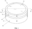
- Figs. 1-3 illustrate one container 10 in accordance with the present disclosure.
- the container 10 may be formed by an open-ended body 20 and a lid 40.
- the lid 40 is removable from the body 20 to provide access to a product held within the container 10.
- the body 20 has a bottom wall 22 (see Fig. 2 ), which, in some instances, may be substantially planar, and a peripheral flange 24 depending from the bottom wall 22 which, in some instances, may be cylindrical as shown.
- the peripheral flange 24 may define a peripheral portion of the container 10 such that the peripheral flange includes an outer peripheral surface 28.
- the bottom wall 22 and the peripheral flange 24 cooperate to define an internal storage compartment 26 for storage of a plurality of units of a product.
- an upper portion 30 of the peripheral flange 24 may define a lip 32 in such a manner that the upper portion 30 the peripheral flange has a neck region 34 of reduced diameter (as compared to the diameter of the remainder of the outer surface of the peripheral flange).
- a projection 39 may extend from the neck region 34 and be provided about the periphery of the upper portion 30 of the peripheral flange 24 to provide an interference fit with the lid 40.
- the lid 40 may be provided for enclosing the units of product within the internal storage compartment 26.
- the lid 40 is typically removably secured to the body 20 by a snap-fit or an interference fit.
- the lid 40 has a laterally-extending wall 42, which, in some instances, may be substantially planar.
- the wall 42 has opposing outer and inner surfaces 44, 46 and defines a periphery.
- the wall 42 has a central axis C extending perpendicularly to the outer and inner surfaces 44, 46.
- a sidewall 48 extends from the inner surface and about the periphery of the wall. In one embodiment, the sidewall 48 extends parallel to the central axis C. In the illustrated example, the sidewall 48 is cylindrical.
- the sidewall 48 of the lid 40 may be received over the peripheral flange 24 of the body 20 so as to form an enclosure therebetween.
- an edge 50 of the sidewall 48 may interact with a surface 36 of the lip 32 to form a stop when the lid 40 is received upon the body 20.
- the edge 50 of the lid 40 which is typically substantially planar, will abut the surface 36 of the lip 32, which is also typically substantially planar, when the lid 40 is fully seated upon the body 20.
- a cylindrical exterior surface 52 of the lid 40 may have the same approximate size or diameter as the peripheral flange 24 of the body 20 such that the lid and body form a smooth exterior surface when the lid is placed over the neck region 34 of the peripheral flange and fully seated upon the body.
- the exterior surface 52 of the lid 40 may have a size or diameter that is larger than the peripheral flange 24 of the body 20 so the user may access the edge 50 of the lid 40 for removing the lid from the body.
- the material for constructing the body 20 can vary.
- Example materials include metal, wood, and synthetic plastic materials.
- the body 20 is formed from a polymeric material. Polymeric materials that can be extruded and/or molded into desired shapes are typically utilized, such as polypropylene, polyethylene, polystyrene, polyamide, and the like.
- Fig. 3 shows an interior perspective view of the lid 40.
- a rib structure 60 projects from the inner surface 46 of the laterally extending wall 42.
- the rib structure 60 may be integrally formed with the wall 42.
- the rib structure 60 may be formed by a plurality of rib segments 62 arranged in spaced relation around the periphery of the wall 42 (e.g., positioned circumferentially about the wall 42 where the lid 40 is cylindrical). Any number of rib segments 62 greater than one may be provided in accordance with the present disclosure (e.g., about 2 to about 20 rib segments or about 5 to about 15 rib segments).
- the rib segments 62 are separated from one another by a vent channel 64.
- each pair of adjacent rib segments 62 may form a vent channel 64 therebetween that allows venting from the interior of the container 10 to the atmosphere exterior of the container.
- the sidewall 48 of the lid 40 may include a radially inward extending detent 68 extending circumferentially around the central axis C of the lid 40.
- the detent 68 may be configured to engage with the projection 39 of the body 20 to assist with retention of the lid 40 on the body 20.
- the laterally extending wall 42, sidewall 48, and rib structure 60 of the lid 40 are integrally formed into a base 70 from polymeric materials.
- Example polymeric materials that can be formed into the base 70 are materials that can be extruded and/or molded into the desired shapes, such as polypropylene, polyethylene, polystyrene, polyamide, and the like.
- the shape of the exterior surface 52 of the lid 40 of the disclosure can vary. Therefore, although the container 10 is represented as a substantially cylindrical "puck" shape, the container 10 may be configured with alternative peripheral shapes, such as a square, a rectangle, various other regular or irregular polygonal shapes, an oval, or other suitable shapes. Further, the sides or edges of the containers of the disclosure could be flattened, rounded, or beveled, and the various surfaces or edges of the container exterior could be concave or convex unless expressly stated otherwise in claimed embodiments. Further, the opposing sides, ends, or edges of the container can be parallel or non-parallel such that the container becomes narrower in one or more dimensions.
- the dimensions of the containers described herein can vary without departing from the disclosure. However, in some examples, the containers of the disclosure can be described as having a cylindrical size suitable for handheld manipulation and operation.
- Example dimensions for such handheld cylindrical embodiments include diameters in the range of about 50 mm to about 100 mm, and more typically about 60 mm to about 80 mm.
- Example wall thicknesses include the range of about 0.5 mm to about 1.5 mm, and more typically about 0.8 mm to about 1.4 mm.
- Example depths for handheld container embodiments of the present disclosure range from about 5 mm to about 50 mm, more typically about 8 mm to about 30 mm, and most often about 15 mm to about 25 mm.
- the number of solid product units stored in the containers of the disclosure can also vary, depending on the size of the container and the size of the product units. Typically, the number of stored product units will vary from about 5 to about 100, more typically about 10 to about 50, and most often about 15 to about 30.
- the polymeric base 70 of the lid 40 which includes at least the laterally extending wall 42 and the sidewall 48, supports a metallic cladding 80 engaged with the wall 42 so as to extend laterally across the outer surface 44 of the wall.
- the cladding 80 comprises a metallic material, such as tin, brass, bronze, nickel, aluminum, steel, or tin coated steel plate.
- the cladding 80 may be formed from a single sheet of metal via punching, stamping, trimming, forming the sheet of metal and/or via other operations.
- Providing a metallic cladding 80 engaged with a polymeric base 70 may be advantageous in that the illustrated combination may provide an aesthetically appealing appearance by using a metallic material to form the prominent merchandizing portion of the container 10, while also allowing the remainder of the base 70 and container to be less expensively produced using, for example, an injection molding process.
- Advantageous examples of the present disclosure utilize an adhesive to bond the cladding 80 to the polymeric base 70.
- the metallic cladding 80 can be bonded to the polymeric base 70 during a molding operation.
- insert molding techniques could be used to affix the cladding 80 to the base 70 during an injection molding process used to create the final shape of the base portion of the lid structure.
- Such processes typically involve placing an insert, in this case a cladding material, within a mold prior to injection of a polymeric material into the mold. As the final polymeric structure is formed, structural integration with the insert takes place.
- the cladding 80 may provide a merchandizing portion of the lid 40 by being embossed with product branding or other aesthetically pleasing or informative labeling 82.
- the labeling 82 may additionally or alternatively be provided integrally with the cladding 80 through other processes such as casting, printing (e.g., infusing dyes into the surface of the cladding), etching (e.g., via various laser, chemical, and/or other suitable etching techniques), or other suitable process for adding text, graphics, and/or other ornamentation to a metal surface.
- the labeling 82 may alternatively be separately attached to the cladding, such as by use of a labeling sticker.
- the cladding 80 may be substantially planar.
- the cladding 80 comprises a metallic sheet having a thickness between about 0.1 mm and about 0.5 mm.
- the metallic sheet has a thickness between about 0.1 mm and about 0.2 mm.
- the cladding 80 may be a foil.
- the cladding 80 may be a coating applied to the base 70.
- the cladding 80 may comprise a film applied to the base 70.
- the cladding 80 may be engaged with the outer surface 44 of the wall 42 using an adhesive layer 84 disposed therebetween.
- the adhesive layer 84 may have a thickness of between about 0.01 mm and about 0.5 mm.
- the adhesive layer 84 is a coating applied to a surface of the cladding 80 in a step separate from joining the cladding to the base 70.
- the coating is a solvent-based polyolefin dispersion heat-seal coating, which may be a heat-actuated adhesive coating.
- a suitable coating may be sold under the tradename MORPRIME TM by the Dow Chemical Company. Acrylic, aqueous heat seal coatings available from Roymal Inc. may also be suitable. Aqueous emulsion waterborne heat-seal coatings available from Mico-Corp may also be suitable.
- the coatings may be applied to the cladding with known processes such as printing, gravure, rotogravure, flexographic, and offset.
- a heat-seal coating or heat-actuated adhesive coating as the adhesive layer 84 allows the cladding 80 to be pre-coated with the adhesive layer for later attachment to the base 70.
- the coating particularly a heat-seal coating, can then be activated by heat to facilitate a bond between the metallic cladding 80 and the polymeric base 70.
- the coating Prior to being heated, the coating may not be tacky, facilitating use of a cladding 80 with an adhesive layer coating in high-speed production lines.
- heat for activing the adhesive layer 84 coating may be created using induction heating.
- Adherence between the cladding 80 with the adhesive layer 84 and the base 70 may be generated using the same or similar methodology as employed within known induction sealing or heat sealing machines.
- Such machines including production line machines, are available from companies such as Relco UK, Selig Sealing Products, Inc., and ME.RO S.p.A, and Enercon Industries.
- Induction sealers would be used to create an electromagnetic field in the presence of the metallic cladding 80. Exposure of the cladding 80 and heat-actuated adhesive layer 84 to the magnetic field induces eddy currents within the cladding that causes the cladding to quickly generate heat therein, wherein the heat would be conducted to the adhesive layer 84.
- Typical induction sealers include a power source, a coil for generating a magnetic field, and a cooling system.
- the lid 40 may have a maximum height along a direction parallel with the central axis C of less than about 8.89 mm (0.35 inches). In another embodiment, the maximum height of the lid 40 may be less than about 7.62 mm (0.30 inches) and may be less than about 7.112 mm (0.28 inches). The height includes both the body 70 and the cladding 80. The same suitable dimensions may apply to the further examples discussed below.
- Figs. 5A and 5B show a lid 40a according to a second example of the present disclosure.
- the interior of the lid 40a may be substantially similar to the lid 40 discussed above, and as a result, the lid 40a may be configured to engage the body 20 in the same manner as discussed above.
- the lid 40a illustrates the cladding 80a extending across substantially the entirety of the top surface 44 of the wall 42. Particularly, as illustrated, the top surface 44 of the polymeric base 70 is substantially entirely hidden from view by the cladding 80a.
- the cladding 80a may include an adhesive layer 84, coated thereon in advance, that may be active by heat through an induction bonding machine as discussed hereinabove.
- Figs. 6A and 6B show a lid 40b according to a third example of the present disclosure.
- the interior of the lid 40b may be substantially similar to the lid 40 discussed above, and as a result, the lid 40b may be configured to engage the body 20 in the same manner as discussed above.
- the cladding 80b is engaged with the wall 42 using an adhesive layer 84, such as the induction bonded, heat seal coating layer described above.
- the wall 48 of the base 70b may also include a groove 49 recessed in the exterior surface 52.
- the groove 49 may be configured to receive the peripheral edge 86 of the cladding 80b.
- the peripheral edge 86 may be bent or otherwise angled to reside in the groove 49.
- the depth of the groove 49 in the radial direction toward axis C may be selected such that the exterior surface 52 is flush with the surface of the cladding 80b when the peripheral edge 86 is disposed within the groove 49.
- the groove 49 is deeper than the thickness of the cladding 80b such that the cladding is recessed relative to the exterior surface 52.
- Figs. 7A and 7B show a lid 40c according to an embodiment of the present invention.
- the interior of the lid 40c may be substantially similar to the lid 40 discussed above, and as a result, the lid 40c may be configured to engage the body 20 in the same manner as discussed above.
- the cladding 80c is engaged with the wall 42 using an adhesive layer 84, such as the induction bonded, heat seal coating layer described above.
- the wall 48 of the base 70b may also include a groove 49 recessed in the exterior surface 52.
- the groove 49 may be configured to receive the peripheral edge 86 of the cladding 80c.
- the peripheral edge 86 may be bent or otherwise angled, such as by stamping, to reside in the groove 49.
- the cladding 80c may be less susceptible to peeling away from the base 70b.
- the depth of the groove 49 in the radial direction toward axis C may be selected such that the exterior surface 52 is flush with the surface of the cladding 80c when the peripheral edge 86 is disposed within the groove 49.
- the groove 49 is deeper than the thickness of the cladding 80c such that the cladding is recessed relative to the exterior surface 52.
- the cladding 80c may be pre-formed, such as by stamping, with a peripheral ridge 87.
- the peripheral ridge 87 may assist with the rigidity of the cladding 80c and help minimize warping near the center of the cladding.
- the peripheral ridge 87 may provide a tactile feature that assist the user with at least one of adding or removing the lid 40c from the body 20 ( FIG. 1 ).
- the material and thickness of the cladding 80c may be selected such that the peripheral ridge 87 is self-supporting and would remain raised under force conditions typical to opening or closing the container 10 and force conditions typically encountered during transportation of the container. By being self-supporting, the peripheral ridge 87 of the cladding 80c may avoid the use of an upward projection formed from the polymeric material of the base 70b.
- the containers 10 of the disclosure can be sealed with a circumferential label or wrapper of a pervious or impervious material.
- the label or wrapping material useful in accordance with the present disclosure can vary. Typically, the selection of the packaging label or wrapper is dependent upon factors such as aesthetics, desired barrier properties (e.g., so as to provide protection from exposure to oxygen, or so as to provide protection from loss of moisture), or the like.
Landscapes
- Engineering & Computer Science (AREA)
- Mechanical Engineering (AREA)
- Packages (AREA)
- Closures For Containers (AREA)
Description
- The present disclosure relates to lids and containers using the same. More particularly, the disclosure relates to lids for packaging products made or derived from tobacco, or that otherwise incorporate tobacco, and are intended for human consumption in a smokeless form.
- Various types of containers for dispensing solid objects, particularly solid products intended for human consumption, are known in the art. Such containers are often characterized by a hand-held size that can be easily stored and transported. Example consumable products that are often packaged in such containers include a wide variety of consumer products, including "smokeless" tobacco-related products.
- Particularly popular smokeless tobacco products are employed by inserting some form of processed tobacco or tobacco-containing formulation into the mouth of the user. See for example, the types of smokeless tobacco formulations, ingredients, and processing methodologies set forth in
U.S. Pat. Nos. 1,376,586 to Schwartz ;3,696,917 to Levi ;4,513,756 to Pittman et al. ;4,528,993 to Sensabaugh, Jr. et al. ;4,624,269 to Story et al. ;4,991,599 to Tibbetts ;4,987,907 to Townsend ;5,092,352 to Sprinkle, III et al. ;5,387,416 to White et al. ;6,668,839 to Williams ;6,834,654 to Williams ;6,953,040 to Atchley et al. ;7,032,601 to Atchley et al. ;7,694,686 to Atchley et al. ;7,810,507 to Dube et al. ;7,819,124 to Strickland et al. ;7,861,728 to Holton, Jr. et al. ;7,901,512 to Quinter et al. ;8,168,855 to Nielsen et al. ;8,336,557 to Kumar et al. ;8,469,036 to Strickland et al. ;8,627,828 to Strickland et al. ; and8,940,344 to Crawford et al. ;U.S. Patent Application Pub. Nos. 2004/0020503 to Williams ;2007/0062549 to Holton, Jr. et al. ;2008/0029116 to Robinson et al. ;2008/0029117 to Mua et al. ;2008/0173317 to Robinson et al. ;2008/0196730 to Engstrom ct al. ;2009/0065013 to Essen ct al. ; and2010/0291245 to Gao ct al. ;PCT Pub. Nos. WO 04/095959 to Arnarp et al. WO 10/132444 to Atchley - Representative smokeless tobacco products that have been marketed include those referred to as CAMEL Snus, CAMEL Orbs, CAMEL Strips and CAMEL Sticks by R. J. Reynolds Tobacco Company; GRIZZLY moist tobacco, KODIAK moist tobacco, LEVI GARRETT loose tobacco and TAYLOR'S PRIDE loose tobacco by American Snuff Company, LLC; KAYAK moist snuff and CHATTANOOGA CHEW chewing tobacco by Swisher International, Inc.; REDMAN chewing tobacco by Pinkerton Tobacco Co. LP; COPENHAGEN moist tobacco, COPENHAGEN Pouches, SKOAL Bandits, SKOAL Pouches, RED SEAL long cut and REVEL Mint Tobacco Packs by U.S. Smokeless Tobacco Company; and MARLBORO Snus and Taboka by Philip Morris USA.
- Representative types of snuff products, commonly referred to as "snus," are manufactured in Europe, particularly in Sweden, by or through companies such as Swedish Match AB, Fiedler & Lundgren AB, Gustavus AB, Skandinavisk Tobakskompagni A/S and Rocker Production AB. Snus products previously or currently available in the U.S.A. have been marketed under the trade names such as CAMEL Snus Frost, CAMEL Snus Original, and CAMEL Snus Spice, CAMEL Snus Mint, CAMEL Snus Mellow, CAMEL Snus Winterchill, and CAMEL Snus Robust by R. J. Reynolds Tobacco Company.
- Snus products, such as CAMEL Snus Original, are commonly supplied in small teabag-like pouches. The pouches are typically a nonwoven fleece material, and contain about 0.4 to 1.5 grams of pasteurized tobacco. These products typically remain in a user's mouth for about 10-30 minutes. Unlike certain other smokeless tobacco products, snus does not require expectoration by the user.
- Smokeless tobacco products have been packaged in tins, "pucks" or "pots" that are manufactured from metal or plastic such as those disclosed in
U.S. Patent Nos. 4,098,421 to Foster ;4,190,170 to Boyd ;8,556,070 to Bried et al. ;8,910,781 to Pipes et al. ; andU.S. Patent Application Pub. Nos. 2010/0065076 to Bergstrom et al. ; and2010/0065077 to Lofgreen-Ohrn et al. - A desirable feature for certain containers configured to store a product such as snus is the protection of the product from environmental effects, particularly those effects that may degrade the product stored in the container. For example, in humid environments, moisture may invade the storage space housing the product, thereby damaging the product or otherwise rendering the product unusable. Conversely, moisture may escape the product and exit the storage space, rendering the product overly dry.
- It would thus be desirable to provide an improved packaging for smokeless tobacco products and the like, wherein the packaging, particularly the lid, is aesthetically pleasing, reasonable to manufacture, and provides various advantageous features, such as protection from environmental effects by venting the container.
-
US 2010/ 043812A1 discloses a can for holding and compacting smokeless tobacco that has a bottom member and a lid. The bottom member has a closed bottom, an open top, and a first compacting vane located within the bottom member. The lid is adapted to slidably fit on the bottom member and has a second compacting vane located within the lid. With smokeless tobacco in the closed can, tobacco located between the first and second vanes in the can is compacted into a tight wad by simply rotating the lid, either clockwise or counter-clockwise, relative to the bottom member. -
US 2011/121009 A1 discloses a composite lid for a container that includes a tubular body carrying an annular upper wall made of sheet metal, in which is defined an opening surrounded by a seat, which is configured to receive and retain the lid. The lid includes a base portion peripherally incorporating a retention portion to be seated and retained on the seat when the lid is closed. The base portion includes a peripheral annular element molded in a plastic material as a single piece with the retention portion, and a central element in the form of a sheet metal plate that has an outer peripheral edge attached to the peripheral annular element. The peripheral annular element includes, internally and in a single piece, a central panel disposed on the central element, which is incorporated to the lid during its injection or attached thereto afterwards. -
GB 943117 A -
US 2009/289074 A1 discloses a container lid which seals about a peripheral lip contacting a corresponding container. A flexible material, such as a silicone rubber, thermoplastic elastomer, or the like, is attached to at least a peripheral lip formed in a flexible substrate, such as a flexible metal or plastic material, having a first and second surface. The peripheral lip includes notches or slots to create individual sections in the lip to allow inward and outward flexing of the sections. When fitted to a container, the coated flexible substrate forms a seal between the container and the container lid. -
US 3782575 A discloses a safety closure for a container having an annular lip and a shoulder adjacent the lip. The closure includes a unitary cap, having a rim and a dome, and a snap-action disc which is coupled to the cap. The rim of the unitary cap includes a locking projection which engages the lip on the container. The closure is placed in an unlocked position by applying a downward force to the snap-action disc to change the disc from a convex position to a concave position. -
GB 1571938 A - In one aspect, a lid is provided. The lid may include a laterally-extending wall having opposing first and second surfaces and defining a periphery. The wall may have a central axis extending perpendicularly to the first and second surfaces. A sidewall may extend from the second surface parallel to the central axis and about the periphery of the wall. The wall and the sidewall are formed of a polymeric material. A metallic cladding is engaged with the wall so as to extend laterally across the first surface. The sidewall includes a groove recessed in an exterior surface thereof and the groove receiving a peripheral edge of the metallic cladding.
- In another aspect, a method of manufacturing a lid for a container for storing a smokeless tobacco product is provided. The method may include coating at least a portion of a surface of a metallic cladding with a heat-actuated adhesive coating. The method may also include arranging the metallic cladding adjacent to a first surface of a laterally-extending wall such that the heat-actuated adhesive coating is positioned between the metallic cladding and the first surface and such that the cladding extends laterally across the first surface. The wall may have a second surface opposing the first surface, defining a periphery, having a central axis extending perpendicularly to the first and second surfaces, and having a sidewall extending from the second surface parallel to the central axis and about the periphery of the wall, with the wall and the sidewall being formed of a polymeric material. The method may also include exposing the metallic cladding and the heat-actuated adhesive coating to a magnetic field so as to actuate the heat-actuated adhesive coating to bond the metallic cladding to the first surface. The invention is defined in the appended claims.
- Having thus described the disclosure in general terms, reference will now be made to the accompanying drawings, which are not necessarily drawn to scale, and wherein:
-
Fig. 1 is a perspective view of a container comprising a lid and a body in a coupled configuration according to the present disclosure; -
Fig. 2 is a top perspective view of the body of the container ofFig. 1 ; -
Fig. 3 is an interior perspective view of the lid of the container ofFig. 1 ; -
Fig. 4A is a sectional view of a portion of a lid of the container according to the present disclosure along line 4-4 ofFig. 1 ; -
Fig. 4B is a detailed sectional view of a portion ofFig. 4A ; -
Fig. 4C is an exploded sectional view ofFig. 4B ; -
Fig. 5A is a sectional view of a portion of a lid of the container according to the present disclosure; -
Fig. 5B is a detailed sectional view of a portion ofFig. 5A ; -
Fig. 6A is a sectional view of a portion of a lid of the container according to the present disclosure; -
Fig. 6B is a detailed sectional view of a portion ofFig. 6A ; -
Fig. 7A is a sectional view of a portion of a lid of the container according to an embodiment of the invention; and -
Fig. 7B is a detailed sectional view of a portion ofFig. 7A . - The present disclosure now will be described more fully hereinafter with reference to certain preferred aspects. These aspects are provided so that this disclosure will be thorough and complete, and will fully convey the scope of the disclosure to those skilled in the art. Indeed, the disclosure may be embodied in many different forms and should not be construed as limited to the aspects set forth herein.
- The lids and containers described in the present application can be used to store a variety of products, but are particularly well-suited for products designed for oral consumption. Example consumable products that are often packaged in such containers include a wide variety of consumer products, including tobacco products in smokeless form.
- Example tobacco products include pelletized tobacco products (e.g., compressed or molded pellets produced from powdered or processed tobacco, such as those formed into the general shape of a coin, cylinder, bean, pellet, sphere, orb, strip, obloid, cube, bead, or the like), extruded or cast pieces of tobacco (e.g., as strips, films, or sheets, including multilayered films formed into a desired shape), products incorporating tobacco carried by a solid substrate (e.g., where substrate materials range from edible grains to inedible cellulosic sticks), extruded or formed tobacco-containing rods or sticks, tobacco-containing capsule-like materials having an outer shell region and an inner body portion region, straw-like (e.g., hollow formed) tobacco-containing shapes, sachets or packets containing tobacco (e.g., snus-like products), pieces of tobacco-containing gum, and the like. Further, example tobacco products include tobacco formulations in a loose form such as, for example, a moist snuff product. Example loose form tobacco used with the containers of the present disclosure may include tobacco formulations associated with, for example, commercially available GRIZZLY moist tobacco products and KODIAK moist tobacco products that are marketed by American Snuff Company, LLC.
- Example smokeless tobacco compositions that can be packaged in the containers of the present disclosure are set forth in, for example,
U.S. Patent Nos. 1,376,586 to Schwartz ;3,368,567 to Speer ;4,513,756 to Pittman et al. ;4,606,357 to Dusek et al ;4,821,749 to Toft et al. ;5,167,244 to Kjerstad ;5,387,416 to White ;6,668,839 to Williams ;7,810,507 to Dube et al. ;7,819,124 to Strickland et al. ;8,469,036 to Strickland et al. ; and8,627,828 to Strickland et al. ; andU.S. Patent Application Pub. No. 2008/0029116 to Robinson et al. Examples of tobacco-containing gum are set forth inU.S. Patent Nos. 4,624,269 to Story et al. ;4,975,270 to Kehoe ; and4,802,498 to Ogren . Various manners or methods for packaging smokeless tobacco products are set forth inU.S. Patent Application Pub. Nos. 2004/0217024 and2006/0118589 to Arnarp et al. ; and2009/0014450 to Bjorkholm ; andPCT Pub. Nos. WO 2006/034450 to Budd ;WO 2007/017761 to Kutsch et al. ; andWO 2007/067953 to Sheveley et al. - Smokeless tobacco compositions utilized as the product contained in the containers of the disclosure will often include such ingredients as tobacco (typically in particulate form), sweeteners, binders, colorants, pH adjusters, fillers, flavoring agents, disintegration aids, antioxidants, oral care additives, and preservatives. See, for example,
U.S. Patent No. 7,861,728 to Holton et al. - The tobacco formulation can be contained within a container, such as a pouch or bag, such as is the type commonly used for the manufacture of snus types of products (e.g., a sealed, moisture permeable pouch that is sometimes referred to as a "portion"). A representative moisture permeable pouch can be composed of a "fleece" type of material. The tobacco formulation is in turn contained within a package, such as the containers of the present disclosure described more fully hereinbelow. The package is closeable, and is composed of a suitable material, such that the atmospheric conditions within that closed package may be modified and/or controlled. In one example, the package can provide a good barrier that inhibits the passage of compositions such as moisture and oxygen therethrough. In addition, the atmosphere within the sealed package can be further modified by introducing a selected gaseous species (e.g., nitrogen, argon, or a mixture thereof) into the package prior to sealing, or by drawing a vacuum therein (vacuum sealing). As such, the atmospheric conditions to which the tobacco composition is exposed may be controlled during conditions of preparation, packing, storage and handling. In other examples, the atmospheric conditions are controlled by allowing for air exchange between the interior of the closed package and the ambient environment. Air exchange may be facilitated by the permeability of the materials or through vents or other structures constructed as a portion of the package. A vented container may be particularly suitable for storing fermented moist tobacco products.
- An example pouch may be manufactured from materials, and in such a manner, such that during use by the user, the pouch undergoes a controlled dispersion or dissolution. Such pouch materials may have the form of a mesh, screen, perforated paper, permeable fabric, or the like. For example, pouch material manufactured from a mesh-like form of rice paper, or perforated rice paper, may dissolve in the mouth of the user. As a result, the pouch and tobacco formulation each may undergo complete dispersion within the mouth of the user during normal conditions of use, and hence the pouch and tobacco formulation both may be ingested by the user. Other example pouch materials may be manufactured using water dispersible film forming materials (e.g., binding agents such as alginates, carboxymethylcellulose, xanthan gum, pullulan, and the like), as well as those materials in combination with materials such as ground cellulosics (e.g., fine particle size wood pulp). Some pouch materials, though water dispersible or dissolvable, may be designed and manufactured such that under conditions of normal use, a significant amount of the tobacco formulation contents permeate through the pouch material prior to the time that the pouch undergoes loss of its physical integrity. If desired, flavoring ingredients, disintegration aids, and other desired components, may be incorporated within, or applied to, the pouch material. Descriptions of various components of snus products and components thereof also are set forth in
U.S. Pat. Pub. No. 2004/0118422 to Lundin et al. - See, also, for example,
U.S. Pat. No. 4,607,479 to Linden ;U.S. Pat. No. 4,631,899 to Nielsen ;U.S. Pat. No. 5,346,734 to Wydick et al. ; andU.S. Pat. No. 6,162,516 to Derr , andU.S. Pat. Pub. No. 2005/0061339 to Hansson et al. See, also, the representative types of pouches, and pouch material or fleece, set forth inU.S. Pat. No. 5,167,244 to Kjerstad. Snus products can be manufactured using equipment such as that available as SB 51-1/T,SBL 50 and SB 53-2/T from Merz Verpackungmaschinen GmbH. G.D SpA out of Italy also supplies tobacco pouching equipment. Snus pouches can be provided as individual pouches, or a plurality of pouches and can be connected or linked together (e.g., in an end-to-end manner) such that a single pouch or individual portion can be readily removed for use from a one-piece strand or matrix of pouches. -
Figs. 1-3 illustrate onecontainer 10 in accordance with the present disclosure. Thecontainer 10 may be formed by an open-endedbody 20 and alid 40. Thelid 40 is removable from thebody 20 to provide access to a product held within thecontainer 10. Thebody 20 has a bottom wall 22 (seeFig. 2 ), which, in some instances, may be substantially planar, and aperipheral flange 24 depending from thebottom wall 22 which, in some instances, may be cylindrical as shown. Theperipheral flange 24 may define a peripheral portion of thecontainer 10 such that the peripheral flange includes an outerperipheral surface 28. Thebottom wall 22 and theperipheral flange 24 cooperate to define aninternal storage compartment 26 for storage of a plurality of units of a product. In some instances, anupper portion 30 of theperipheral flange 24 may define alip 32 in such a manner that theupper portion 30 the peripheral flange has aneck region 34 of reduced diameter (as compared to the diameter of the remainder of the outer surface of the peripheral flange). Note that the location of thelip 32 along theperipheral flange 24 of thebody 20 can vary without departing from the present disclosure, meaning that distance between thelip 32 and thetop edge 38 of thebody 20 is not critical to the present disclosure. Aprojection 39 may extend from theneck region 34 and be provided about the periphery of theupper portion 30 of theperipheral flange 24 to provide an interference fit with thelid 40. - The
lid 40 may be provided for enclosing the units of product within theinternal storage compartment 26. In this regard, thelid 40 is typically removably secured to thebody 20 by a snap-fit or an interference fit. As shown inFig. 1 , thelid 40 has a laterally-extendingwall 42, which, in some instances, may be substantially planar. Thewall 42 has opposing outer andinner surfaces wall 42 has a central axis C extending perpendicularly to the outer andinner surfaces sidewall 48 extends from the inner surface and about the periphery of the wall. In one embodiment, thesidewall 48 extends parallel to the central axis C. In the illustrated example, thesidewall 48 is cylindrical. Thesidewall 48 of thelid 40 may be received over theperipheral flange 24 of thebody 20 so as to form an enclosure therebetween. In instances where thelip 32 is provided on thebody 20, anedge 50 of thesidewall 48 may interact with asurface 36 of thelip 32 to form a stop when thelid 40 is received upon thebody 20. In other words, theedge 50 of thelid 40, which is typically substantially planar, will abut thesurface 36 of thelip 32, which is also typically substantially planar, when thelid 40 is fully seated upon thebody 20. Acylindrical exterior surface 52 of thelid 40 may have the same approximate size or diameter as theperipheral flange 24 of thebody 20 such that the lid and body form a smooth exterior surface when the lid is placed over theneck region 34 of the peripheral flange and fully seated upon the body. In another example, theexterior surface 52 of thelid 40 may have a size or diameter that is larger than theperipheral flange 24 of thebody 20 so the user may access theedge 50 of thelid 40 for removing the lid from the body. - The material for constructing the
body 20 can vary. Example materials include metal, wood, and synthetic plastic materials. In one example, thebody 20 is formed from a polymeric material. Polymeric materials that can be extruded and/or molded into desired shapes are typically utilized, such as polypropylene, polyethylene, polystyrene, polyamide, and the like. -
Fig. 3 shows an interior perspective view of thelid 40. Arib structure 60 projects from theinner surface 46 of the laterally extendingwall 42. In some aspects, therib structure 60 may be integrally formed with thewall 42. According to some aspects of the present disclosure, therib structure 60 may be formed by a plurality ofrib segments 62 arranged in spaced relation around the periphery of the wall 42 (e.g., positioned circumferentially about thewall 42 where thelid 40 is cylindrical). Any number ofrib segments 62 greater than one may be provided in accordance with the present disclosure (e.g., about 2 to about 20 rib segments or about 5 to about 15 rib segments). Therib segments 62 are separated from one another by avent channel 64. - When the
lid 40 is engaged with thebody 20, each pair ofadjacent rib segments 62 may form avent channel 64 therebetween that allows venting from the interior of thecontainer 10 to the atmosphere exterior of the container. - The
sidewall 48 of thelid 40 may include a radially inward extendingdetent 68 extending circumferentially around the central axis C of thelid 40. Thedetent 68 may be configured to engage with theprojection 39 of thebody 20 to assist with retention of thelid 40 on thebody 20. - In an example, the laterally extending
wall 42,sidewall 48, andrib structure 60 of thelid 40 are integrally formed into a base 70 from polymeric materials. Example polymeric materials that can be formed into the base 70 are materials that can be extruded and/or molded into the desired shapes, such as polypropylene, polyethylene, polystyrene, polyamide, and the like. - The shape of the
exterior surface 52 of thelid 40 of the disclosure can vary. Therefore, although thecontainer 10 is represented as a substantially cylindrical "puck" shape, thecontainer 10 may be configured with alternative peripheral shapes, such as a square, a rectangle, various other regular or irregular polygonal shapes, an oval, or other suitable shapes. Further, the sides or edges of the containers of the disclosure could be flattened, rounded, or beveled, and the various surfaces or edges of the container exterior could be concave or convex unless expressly stated otherwise in claimed embodiments. Further, the opposing sides, ends, or edges of the container can be parallel or non-parallel such that the container becomes narrower in one or more dimensions. - The dimensions of the containers described herein can vary without departing from the disclosure. However, in some examples, the containers of the disclosure can be described as having a cylindrical size suitable for handheld manipulation and operation. Example dimensions for such handheld cylindrical embodiments include diameters in the range of about 50 mm to about 100 mm, and more typically about 60 mm to about 80 mm. Example wall thicknesses include the range of about 0.5 mm to about 1.5 mm, and more typically about 0.8 mm to about 1.4 mm. Example depths for handheld container embodiments of the present disclosure range from about 5 mm to about 50 mm, more typically about 8 mm to about 30 mm, and most often about 15 mm to about 25 mm.
- The number of solid product units stored in the containers of the disclosure can also vary, depending on the size of the container and the size of the product units. Typically, the number of stored product units will vary from about 5 to about 100, more typically about 10 to about 50, and most often about 15 to about 30.
- Turning to
Figs. 4A-C , a cross section of thelid 40 according to a first example, which is not part of the invention, is illustrated in further detail. Notably, thepolymeric base 70 of thelid 40, which includes at least the laterally extendingwall 42 and thesidewall 48, supports ametallic cladding 80 engaged with thewall 42 so as to extend laterally across theouter surface 44 of the wall. - The
cladding 80 comprises a metallic material, such as tin, brass, bronze, nickel, aluminum, steel, or tin coated steel plate. Thecladding 80 may be formed from a single sheet of metal via punching, stamping, trimming, forming the sheet of metal and/or via other operations. Providing ametallic cladding 80 engaged with apolymeric base 70 may be advantageous in that the illustrated combination may provide an aesthetically appealing appearance by using a metallic material to form the prominent merchandizing portion of thecontainer 10, while also allowing the remainder of thebase 70 and container to be less expensively produced using, for example, an injection molding process. - Advantageous examples of the present disclosure utilize an adhesive to bond the
cladding 80 to thepolymeric base 70. Alternatively, themetallic cladding 80 can be bonded to thepolymeric base 70 during a molding operation. For example, insert molding techniques could be used to affix thecladding 80 to the base 70 during an injection molding process used to create the final shape of the base portion of the lid structure. Such processes typically involve placing an insert, in this case a cladding material, within a mold prior to injection of a polymeric material into the mold. As the final polymeric structure is formed, structural integration with the insert takes place. - The
cladding 80 may provide a merchandizing portion of thelid 40 by being embossed with product branding or other aesthetically pleasing orinformative labeling 82. Thelabeling 82 may additionally or alternatively be provided integrally with thecladding 80 through other processes such as casting, printing (e.g., infusing dyes into the surface of the cladding), etching (e.g., via various laser, chemical, and/or other suitable etching techniques), or other suitable process for adding text, graphics, and/or other ornamentation to a metal surface. Thelabeling 82 may alternatively be separately attached to the cladding, such as by use of a labeling sticker. - As illustrated in
Figs. 4A-C , thecladding 80 may be substantially planar. In one example, thecladding 80 comprises a metallic sheet having a thickness between about 0.1 mm and about 0.5 mm. In one example, the metallic sheet has a thickness between about 0.1 mm and about 0.2 mm. Thecladding 80 may be a foil. In other examples, thecladding 80 may be a coating applied to thebase 70. In further examples, thecladding 80 may comprise a film applied to thebase 70. As illustrated inFigs. 4A-C , thecladding 80 may be engaged with theouter surface 44 of thewall 42 using anadhesive layer 84 disposed therebetween. Theadhesive layer 84 may have a thickness of between about 0.01 mm and about 0.5 mm. In one example, as shown in the exploded view ofFig. 4C , theadhesive layer 84 is a coating applied to a surface of thecladding 80 in a step separate from joining the cladding to thebase 70. In one embodiment, the coating is a solvent-based polyolefin dispersion heat-seal coating, which may be a heat-actuated adhesive coating. In one example, a suitable coating may be sold under the tradename MORPRIME™ by the Dow Chemical Company. Acrylic, aqueous heat seal coatings available from Roymal Inc. may also be suitable. Aqueous emulsion waterborne heat-seal coatings available from Mico-Corp may also be suitable. The coatings may be applied to the cladding with known processes such as printing, gravure, rotogravure, flexographic, and offset. - Use of a heat-seal coating or heat-actuated adhesive coating as the
adhesive layer 84 allows thecladding 80 to be pre-coated with the adhesive layer for later attachment to thebase 70. The coating, particularly a heat-seal coating, can then be activated by heat to facilitate a bond between themetallic cladding 80 and thepolymeric base 70. Prior to being heated, the coating may not be tacky, facilitating use of acladding 80 with an adhesive layer coating in high-speed production lines. - In one example, heat for activing the
adhesive layer 84 coating may be created using induction heating. Adherence between thecladding 80 with theadhesive layer 84 and the base 70 may be generated using the same or similar methodology as employed within known induction sealing or heat sealing machines. Such machines, including production line machines, are available from companies such as Relco UK, Selig Sealing Products, Inc., and ME.RO S.p.A, and Enercon Industries. Induction sealers would be used to create an electromagnetic field in the presence of themetallic cladding 80. Exposure of thecladding 80 and heat-actuatedadhesive layer 84 to the magnetic field induces eddy currents within the cladding that causes the cladding to quickly generate heat therein, wherein the heat would be conducted to theadhesive layer 84. The heating of theadhesive layer 84 activates or otherwise actuates theadhesive layer 84 to form a bond between thecladding 80 and thebase 70. Typical induction sealers include a power source, a coil for generating a magnetic field, and a cooling system. - The
lid 40 may have a maximum height along a direction parallel with the central axis C of less than about 8.89 mm (0.35 inches). In another embodiment, the maximum height of thelid 40 may be less than about 7.62 mm (0.30 inches) and may be less than about 7.112 mm (0.28 inches). The height includes both thebody 70 and thecladding 80. The same suitable dimensions may apply to the further examples discussed below. -
Figs. 5A and 5B show alid 40a according to a second example of the present disclosure. The interior of thelid 40a may be substantially similar to thelid 40 discussed above, and as a result, thelid 40a may be configured to engage thebody 20 in the same manner as discussed above. - The
lid 40a illustrates thecladding 80a extending across substantially the entirety of thetop surface 44 of thewall 42. Particularly, as illustrated, thetop surface 44 of thepolymeric base 70 is substantially entirely hidden from view by thecladding 80a. Thecladding 80a may include anadhesive layer 84, coated thereon in advance, that may be active by heat through an induction bonding machine as discussed hereinabove. -
Figs. 6A and 6B show a lid 40b according to a third example of the present disclosure. The interior of the lid 40b may be substantially similar to thelid 40 discussed above, and as a result, the lid 40b may be configured to engage thebody 20 in the same manner as discussed above. - In the illustrated example of
Figs. 6A and 6B , thecladding 80b is engaged with thewall 42 using anadhesive layer 84, such as the induction bonded, heat seal coating layer described above. - The
wall 48 of thebase 70b may also include agroove 49 recessed in theexterior surface 52. Thegroove 49 may be configured to receive theperipheral edge 86 of thecladding 80b. In the illustrated example, theperipheral edge 86 may be bent or otherwise angled to reside in thegroove 49. By positioning theperipheral edge 86 within thegroove 49, thecladding 80b may be less susceptible to peeling away from thebase 70b. The depth of thegroove 49 in the radial direction toward axis C may be selected such that theexterior surface 52 is flush with the surface of thecladding 80b when theperipheral edge 86 is disposed within thegroove 49. In another example, thegroove 49 is deeper than the thickness of thecladding 80b such that the cladding is recessed relative to theexterior surface 52. -
Figs. 7A and 7B show alid 40c according to an embodiment of the present invention. The interior of thelid 40c may be substantially similar to thelid 40 discussed above, and as a result, thelid 40c may be configured to engage thebody 20 in the same manner as discussed above. - In the illustrated embodiment of
Figs. 7A and 7B , thecladding 80c is engaged with thewall 42 using anadhesive layer 84, such as the induction bonded, heat seal coating layer described above. - The
wall 48 of thebase 70b may also include agroove 49 recessed in theexterior surface 52. Thegroove 49 may be configured to receive theperipheral edge 86 of thecladding 80c. In the illustrated embodiment, theperipheral edge 86 may be bent or otherwise angled, such as by stamping, to reside in thegroove 49. By positioning theperipheral edge 86 within thegroove 49, thecladding 80c may be less susceptible to peeling away from thebase 70b. The depth of thegroove 49 in the radial direction toward axis C may be selected such that theexterior surface 52 is flush with the surface of thecladding 80c when theperipheral edge 86 is disposed within thegroove 49. In another embodiment, thegroove 49 is deeper than the thickness of thecladding 80c such that the cladding is recessed relative to theexterior surface 52. - In the illustrated embodiment of
Figs. 7A and 7B , thecladding 80c may be pre-formed, such as by stamping, with aperipheral ridge 87. Theperipheral ridge 87 may assist with the rigidity of thecladding 80c and help minimize warping near the center of the cladding. In addition, theperipheral ridge 87 may provide a tactile feature that assist the user with at least one of adding or removing thelid 40c from the body 20 (FIG. 1 ). The material and thickness of thecladding 80c may be selected such that theperipheral ridge 87 is self-supporting and would remain raised under force conditions typical to opening or closing thecontainer 10 and force conditions typically encountered during transportation of the container. By being self-supporting, theperipheral ridge 87 of thecladding 80c may avoid the use of an upward projection formed from the polymeric material of thebase 70b. - Returning to
Fig. 1 , as part of the final packaging process, once thecontainers 10 of the disclosure are filled with the desired product, the containers can be sealed with a circumferential label or wrapper of a pervious or impervious material. The label or wrapping material useful in accordance with the present disclosure can vary. Typically, the selection of the packaging label or wrapper is dependent upon factors such as aesthetics, desired barrier properties (e.g., so as to provide protection from exposure to oxygen, or so as to provide protection from loss of moisture), or the like.
Claims (12)
- A lid (40, 40c) for a container (10) for storing a smokeless tobacco product, the lid (40, 40c) comprising:a laterally-extending wall (42) having opposing first and second surfaces (44, 46) and defining a periphery, the laterally-extending wall (42) having a central axis (C) extending perpendicularly to the first and second surfaces (44, 46);a sidewall (48) extending from the second surface (46) about the periphery of the laterally-extending wall (42), with the laterally-extending wall (42) and the sidewall (48) being formed of a polymeric material;a metallic cladding (80, 80c) comprising a metallic sheet, said metallic sheet comprisinga raised ridge (87) adjacent to a periphery thereof, the metallic cladding (80, 80c) engaged with the laterally-extending wall (42) so as to extend laterally across the first surface (44), wherein the sidewall (48) includes a groove (49) receiving a peripheral edge (86) of the metallic cladding (80c said lid being characterised in that:
said groove (49) is recessed in an exterior surface of said sidewall (48). - The lid (40, 40c) of claim 1, wherein the peripheral edge (86) of the cladding (80, 80c) is angled to reside in the groove (49).
- The lid (40, 40c) of claim 1, wherein the groove (49) is recessed radially inward toward the central axis (C) of the laterally-extending wall (42) from the exterior surface of the sidewall by a distance greater than or about equal to a thickness of the cladding; and optionally:wherein the metallic sheet is embossed; and optionallywherein the raised ridge (87) is self-supporting; and optionallywherein the metallic sheet has a thickness between about 0.1 mm and about 0.5 mm; and optionallywherein the sidewall (48) extends substantially parallel to the central axis (C) of the laterally-extending wall (42).
- The lid (40, 40c) of claim 1, further comprising a rib structure (60) projecting from the second surface (46) of the laterally-extending wall (42), the rib structure (60) comprising a plurality of rib segments (62) arranged in spaced relation proximate the periphery of the laterally-extending wall (42).
- The lid (40, 40c) of claim 1, wherein the sidewall (48) further comprises a radially inward extending detent (68) extending circumferentially around the central axis (C) of the laterally-extending wall (42).
- The lid (40, 40c) of claim 1, wherein an adhesive layer (84) is positioned between the cladding (80, 80c) and the first surface (44); and optionallywherein the adhesive layer (84) is a coating which can be pre-applied to the cladding (80, 80c); and optionallywherein the adhesive layer (84) can be actuated by heat to form a bond between the cladding (80, 80c) and the wall (42) when the cladding is subjected to a magnetic field; and optionallywherein the adhesive layer (84) comprises a heat-actuated adhesive.
- A method of manufacturing a lid (40, 40c) for a container (10) for storing a smokeless tobacco product, the method comprising:receiving a lid structure (40, 40c) comprising a laterally-extending wall (42) having opposing first and second surfaces (44, 46) and defining a periphery, the laterally-extending wall (42) having a central axis (C) extending perpendicularly to the first and second surfaces (44, 46), and a sidewall (48) extending from the second surface (46) about the periphery of the laterally-extending wall (42) wherein said sidewall (48) includes a groove (49) recessed in an exterior surface thereof, with the laterally-extending wall (42) and the sidewall (48) being formed of a polymeric material;receiving a metallic cladding (80, 80c), wherein the metallic cladding (80, 80c) comprises a metallic sheet, said metallic sheet comprising a raised ridge (87) adjacent to a periphery thereofarranging the metallic cladding (80, 80c) adjacent to the first surface (44) of the laterally-extending wall (42) such that the metallic cladding (80, 80c) extends laterally across the first surface (44) with a heat activated adhesive (84) positioned between the metallic cladding (80, 80c) and the first surface (44);arranging a peripheral edge (86) of the metallic cladding (80, 80c) within the groove (49):exposing the metallic cladding (80, 80c) and the heat-actuated adhesive (84) to heat so as to actuate the heat-actuated adhesive to bond the metallic cladding (80, 80c) to the first surface (44).
- The method of claim 7, further comprising embossing the metallic cladding (80, 80c).
- The method of claim 7, further comprising the step of coating the heat-actuated adhesive (84) onto either at least a portion of a surface of the metallic cladding (80, 80c) or at least a portion of the first surface (44) of the laterally-extending wall (42) of the lid structure (40, 40c) prior to said arranging step.
- The method of claim 9, wherein the coating step comprises printing the heat-actuated adhesive (84) on at least a portion of a surface of the metallic cladding (80, 80c).
- The method of claim 7, wherein either the metallic cladding (80, 80c) or the lid structure (40, 40c) is received pre-treated with the heat-actuated adhesive (84).
- The method of claim 7, wherein exposing the
the metallic cladding (80, 80c) and the heat-actuated adhesive (84) to heat comprises using an induction sealer.
Applications Claiming Priority (3)
| Application Number | Priority Date | Filing Date | Title |
|---|---|---|---|
| US201862657327P | 2018-04-13 | 2018-04-13 | |
| US201862737496P | 2018-09-27 | 2018-09-27 | |
| PCT/IB2019/053050 WO2019198055A2 (en) | 2018-04-13 | 2019-04-12 | Lid for a container for smokeless tobacco products |
Publications (2)
| Publication Number | Publication Date |
|---|---|
| EP3774570A2 EP3774570A2 (en) | 2021-02-17 |
| EP3774570B1 true EP3774570B1 (en) | 2022-04-27 |
Family
ID=66647435
Family Applications (1)
| Application Number | Title | Priority Date | Filing Date |
|---|---|---|---|
| EP19726486.4A Active EP3774570B1 (en) | 2018-04-13 | 2019-04-12 | Lid for a container for smokeless tobacco products and method of manufacturing such a lid |
Country Status (4)
| Country | Link |
|---|---|
| US (1) | US20200277110A1 (en) |
| EP (1) | EP3774570B1 (en) |
| DK (1) | DK3774570T3 (en) |
| WO (1) | WO2019198055A2 (en) |
Families Citing this family (8)
| Publication number | Priority date | Publication date | Assignee | Title |
|---|---|---|---|---|
| US12070059B2 (en) * | 2020-09-04 | 2024-08-27 | Nicoventures Trading Limited | Child-resistant container for tobacco-containing products |
| US20220135296A1 (en) * | 2020-10-29 | 2022-05-05 | Terence H. Wendelken | Removable magnetic lid for a container |
| USD1029370S1 (en) * | 2021-05-28 | 2024-05-28 | Sävjo Plastic | Snuffbox |
| WO2024074988A1 (en) | 2022-10-04 | 2024-04-11 | R. J. Reynolds Tobacco Company | Stackable arrangement of product containers and related method of stacking |
| US11975898B1 (en) | 2022-10-12 | 2024-05-07 | Altria Client Services Llc | Child-resistant lid for a container |
| US12221264B1 (en) * | 2023-02-23 | 2025-02-11 | Charles Michael Scudder | Terpene preservation system and method |
| WO2025068817A1 (en) | 2023-09-29 | 2025-04-03 | R. J. Reynolds Tobacco Company | Apparatus and system for recovering material from oral wrapped products and related method |
| EP4620318A1 (en) | 2024-03-21 | 2025-09-24 | Nicoventures Trading Limited | Pouched product with humectant |
Family Cites Families (61)
| Publication number | Priority date | Publication date | Assignee | Title |
|---|---|---|---|---|
| US1376586A (en) | 1918-04-06 | 1921-05-03 | Schwartz Francis | Tobacco-tablet |
| GB943117A (en) * | 1961-01-10 | 1963-11-27 | Metal Containers Ltd | Improvements in or relating to containers and closures therefor |
| US3368567A (en) | 1965-03-23 | 1968-02-13 | Morton Pharmaceuticals Inc | Method of producing a tablet containing a tobacco concentrate |
| US3696917A (en) | 1970-09-10 | 1972-10-10 | Elaine G Levi | Tobacco pouch closure |
| US3782575A (en) * | 1972-03-06 | 1974-01-01 | T Braun | Safety closure |
| CA1095459A (en) * | 1976-06-07 | 1981-02-10 | Donald H. Ellerbrock | Patch-top containing a closure |
| US4098421A (en) | 1977-06-24 | 1978-07-04 | J. L. Clark Manufacturing Co. | Container for snuff or the like |
| US4190170A (en) | 1979-01-15 | 1980-02-26 | United States Tobacco Company | Snuff can and the like |
| US4528993A (en) | 1982-08-20 | 1985-07-16 | R. J. Reynolds Tobacco Company | Process for producing moist snuff |
| US4513756A (en) | 1983-04-28 | 1985-04-30 | The Pinkerton Tobacco Company | Process of making tobacco pellets |
| DK149920C (en) | 1983-09-20 | 1987-05-18 | Krueger S Eftf A S Hermann | PROCEDURES FOR PORTIONING OF SNUPS AND PACKAGING OF THE SINGLE SNIPPORTS |
| US5092352A (en) | 1983-12-14 | 1992-03-03 | American Brands, Inc. | Chewing tobacco product |
| SE450566B (en) | 1983-12-14 | 1987-07-06 | Svenska Tobaks Ab | DEVICE FOR PORTION PACKING |
| US4624269A (en) | 1984-09-17 | 1986-11-25 | The Pinkerton Tobacco Company | Chewable tobacco based product |
| US4606357A (en) | 1984-11-19 | 1986-08-19 | Dusek Russell L | Tobacco composition |
| US4975270A (en) | 1987-04-21 | 1990-12-04 | Nabisco Brands, Inc. | Elastomer encased active ingredients |
| US4802498A (en) | 1987-07-02 | 1989-02-07 | Warren Ogren | Resin-based chewing tobacco |
| US4821749A (en) | 1988-01-22 | 1989-04-18 | R. J. Reynolds Tobacco Company | Extruded tobacco materials |
| US4987907A (en) | 1988-06-29 | 1991-01-29 | Helme Tobacco Company | Chewing tobacco composition and process for producing same |
| US4991599A (en) | 1989-12-20 | 1991-02-12 | Tibbetts Hubert M | Fiberless tobacco product for smoking and chewing |
| US5167244A (en) | 1990-01-19 | 1992-12-01 | Kjerstad Randy E | Tobacco substitute |
| US5346734A (en) | 1993-04-16 | 1994-09-13 | Bethanie K. Wydick | Perforated latex oral pouch for loose snuff |
| US5387416A (en) | 1993-07-23 | 1995-02-07 | R. J. Reynolds Tobacco Company | Tobacco composition |
| WO1997013419A2 (en) | 1995-10-11 | 1997-04-17 | Derr Dedric M | System and method for protecting oral tissues from smokeless tobacco |
| US6668839B2 (en) | 2001-05-01 | 2003-12-30 | Jonnie R. Williams | Smokeless tobacco product |
| US20040020503A1 (en) | 2001-05-01 | 2004-02-05 | Williams Jonnie R. | Smokeless tobacco product |
| OA12601A (en) | 2001-05-01 | 2006-06-09 | Jonnie R Williams | Smokeless tobacco product. |
| US6953040B2 (en) | 2001-09-28 | 2005-10-11 | U.S. Smokeless Tobacco Company | Tobacco mint plant material product |
| US7032601B2 (en) | 2001-09-28 | 2006-04-25 | U.S. Smokeless Tobacco Company | Encapsulated materials |
| DE60224832T2 (en) | 2001-12-21 | 2009-01-22 | Galenica Ab | TOBACCO AND / OR TOBACCO IN COMBINATION WITH TOBACCO SUBSTITUTE COMPOSITION FOR USE AS A BUTCH IN THE MOUTH VALVE |
| US20040118422A1 (en) | 2002-12-19 | 2004-06-24 | Swedish Match North Europe Ab | Tobacco dough and a method for its manufacture |
| US20040217024A1 (en) | 2003-04-29 | 2004-11-04 | Jan Arnarp | Smokeless tobacco product user package |
| SE0301244D0 (en) | 2003-04-29 | 2003-04-29 | Swedish Match North Europe Ab | Smokeless tobacco product user package |
| SE527350C8 (en) | 2003-08-18 | 2006-03-21 | Gallaher Snus Ab | Lid for snuff box |
| AU2004285589A1 (en) | 2003-11-03 | 2005-05-12 | U.S. Smokeless Tobacco Company | Flavored smokeless tobacco and methods of making |
| US8627828B2 (en) | 2003-11-07 | 2014-01-14 | U.S. Smokeless Tobacco Company Llc | Tobacco compositions |
| AU2004289248B2 (en) | 2003-11-07 | 2012-05-03 | U.S. Smokeless Tobacco Company Llc | Tobacco compositions |
| EP1729602A1 (en) | 2003-12-22 | 2006-12-13 | U.S. Smokeless Tobacco Company | Conditioning process for tobacco and/or snuff compositions |
| US20080196730A1 (en) | 2004-07-02 | 2008-08-21 | Radi Medical Systems Ab | Smokeless Tobacco Product |
| US20060060480A1 (en) | 2004-09-21 | 2006-03-23 | Budd James P | Smokeless tobacco container with improved cover |
| US7537110B2 (en) | 2005-06-02 | 2009-05-26 | Philip Morris Usa Inc. | Container for consumer article |
| US20070062549A1 (en) | 2005-09-22 | 2007-03-22 | Holton Darrell E Jr | Smokeless tobacco composition |
| US7861728B2 (en) | 2006-02-10 | 2011-01-04 | R.J. Reynolds Tobacco Company | Smokeless tobacco composition having an outer and inner pouch |
| US20070130811A1 (en) | 2005-12-09 | 2007-06-14 | U.S. Smokeless Tobacco Company | Tamper evident label |
| US7819124B2 (en) | 2006-01-31 | 2010-10-26 | U.S. Smokeless Tobacco Company | Tobacco articles and methods |
| US7810507B2 (en) | 2006-02-10 | 2010-10-12 | R. J. Reynolds Tobacco Company | Smokeless tobacco composition |
| SE529886C2 (en) | 2006-04-28 | 2007-12-18 | Swedish Match North Europe Ab | A new method for preparing a moisturizing snuff composition that does not contain tobacco |
| US20080029116A1 (en) | 2006-08-01 | 2008-02-07 | John Howard Robinson | Smokeless tobacco |
| US20080173317A1 (en) | 2006-08-01 | 2008-07-24 | John Howard Robinson | Smokeless tobacco |
| US20080029117A1 (en) | 2006-08-01 | 2008-02-07 | John-Paul Mua | Smokeless Tobacco |
| SE530736C2 (en) | 2006-11-28 | 2008-08-26 | Snusmumrik Hb | sNUFFBOX |
| CN101686731B (en) | 2007-02-23 | 2013-05-08 | 美国无烟烟草有限责任公司 | Novel tobacco composition and preparation method |
| US8940344B2 (en) | 2007-06-08 | 2015-01-27 | Philip Morris Usa Inc. | Capsule clusters for oral consumption |
| MX2010002307A (en) * | 2007-08-31 | 2010-03-22 | Brasilata Embalagens Metalicas | Composite lid for containers. |
| US8336557B2 (en) | 2007-11-28 | 2012-12-25 | Philip Morris Usa Inc. | Smokeless compressed tobacco product for oral consumption |
| US7798319B1 (en) | 2008-03-11 | 2010-09-21 | U.S. Smokeless Tobacco Company | Container device for tobacco articles |
| US20090289074A1 (en) * | 2008-05-23 | 2009-11-26 | Helen Of Troy | Cotainer lid |
| US20100043812A1 (en) * | 2008-08-22 | 2010-02-25 | Benjamin James Yount | Can for making quiet pack of smokeless tobacco |
| US9155772B2 (en) | 2008-12-08 | 2015-10-13 | Philip Morris Usa Inc. | Soft, chewable and orally dissolvable and/or disintegrable products |
| US11246334B2 (en) | 2009-05-11 | 2022-02-15 | Altria Client Services Llc | Method and device for flavoring smokeless tobacco |
| US8910781B2 (en) | 2013-01-11 | 2014-12-16 | R.J. Reynolds Tobacco Company | Container for smokeless tobacco products and related packaged product assembly and method |
-
2019
- 2019-04-12 EP EP19726486.4A patent/EP3774570B1/en active Active
- 2019-04-12 DK DK19726486.4T patent/DK3774570T3/en active
- 2019-04-12 WO PCT/IB2019/053050 patent/WO2019198055A2/en not_active Ceased
-
2020
- 2020-05-15 US US16/875,732 patent/US20200277110A1/en not_active Abandoned
Also Published As
| Publication number | Publication date |
|---|---|
| US20200277110A1 (en) | 2020-09-03 |
| WO2019198055A2 (en) | 2019-10-17 |
| EP3774570A2 (en) | 2021-02-17 |
| WO2019198055A3 (en) | 2019-11-14 |
| DK3774570T3 (en) | 2022-05-23 |
Similar Documents
| Publication | Publication Date | Title |
|---|---|---|
| EP3774570B1 (en) | Lid for a container for smokeless tobacco products and method of manufacturing such a lid | |
| EP2670681B1 (en) | Container for smokeless tobacco products | |
| US9717272B2 (en) | Container for smokeless tobacco product | |
| EP3755641B1 (en) | Container for smokeless tobacco products | |
| US11622575B2 (en) | Container for smokeless tobacco products comprising a pulp material and related packaged product assembly and method | |
| EP3206967B1 (en) | Package for a tobacco-containing material with a valve assembly and related packaging method | |
| US9936729B2 (en) | Package for a tobacco-containing material and related packaging method | |
| US8910781B2 (en) | Container for smokeless tobacco products and related packaged product assembly and method | |
| US12577021B2 (en) | Sealing member for packaging | |
| WO2010027730A1 (en) | Container for holding small items | |
| US20150320113A1 (en) | Containers, Convertible Packaging Devices, Packaged Product Assemblies, and Product Display Methods for Smokeless Tobacco Products | |
| US20150321787A1 (en) | Containers, Convertible Packaging Devices, Packaged Product Assemblies, and Product Display Methods for Smokeless Tobacco Products | |
| EA010515B1 (en) | Wrapped container with label | |
| RU2772155C2 (en) | Container for smoke-free tobacco products |
Legal Events
| Date | Code | Title | Description |
|---|---|---|---|
| STAA | Information on the status of an ep patent application or granted ep patent |
Free format text: STATUS: UNKNOWN |
|
| STAA | Information on the status of an ep patent application or granted ep patent |
Free format text: STATUS: THE INTERNATIONAL PUBLICATION HAS BEEN MADE |
|
| PUAI | Public reference made under article 153(3) epc to a published international application that has entered the european phase |
Free format text: ORIGINAL CODE: 0009012 |
|
| STAA | Information on the status of an ep patent application or granted ep patent |
Free format text: STATUS: REQUEST FOR EXAMINATION WAS MADE |
|
| 17P | Request for examination filed |
Effective date: 20201014 |
|
| AK | Designated contracting states |
Kind code of ref document: A2 Designated state(s): AL AT BE BG CH CY CZ DE DK EE ES FI FR GB GR HR HU IE IS IT LI LT LU LV MC MK MT NL NO PL PT RO RS SE SI SK SM TR |
|
| AX | Request for extension of the european patent |
Extension state: BA ME |
|
| DAV | Request for validation of the european patent (deleted) | ||
| DAX | Request for extension of the european patent (deleted) | ||
| GRAP | Despatch of communication of intention to grant a patent |
Free format text: ORIGINAL CODE: EPIDOSNIGR1 |
|
| STAA | Information on the status of an ep patent application or granted ep patent |
Free format text: STATUS: GRANT OF PATENT IS INTENDED |
|
| INTG | Intention to grant announced |
Effective date: 20211112 |
|
| GRAS | Grant fee paid |
Free format text: ORIGINAL CODE: EPIDOSNIGR3 |
|
| GRAA | (expected) grant |
Free format text: ORIGINAL CODE: 0009210 |
|
| STAA | Information on the status of an ep patent application or granted ep patent |
Free format text: STATUS: THE PATENT HAS BEEN GRANTED |
|
| AK | Designated contracting states |
Kind code of ref document: B1 Designated state(s): AL AT BE BG CH CY CZ DE DK EE ES FI FR GB GR HR HU IE IS IT LI LT LU LV MC MK MT NL NO PL PT RO RS SE SI SK SM TR |
|
| REG | Reference to a national code |
Ref country code: GB Ref legal event code: FG4D |
|
| REG | Reference to a national code |
Ref country code: CH Ref legal event code: EP |
|
| REG | Reference to a national code |
Ref country code: DE Ref legal event code: R096 Ref document number: 602019014191 Country of ref document: DE |
|
| REG | Reference to a national code |
Ref country code: AT Ref legal event code: REF Ref document number: 1486797 Country of ref document: AT Kind code of ref document: T Effective date: 20220515 |
|
| REG | Reference to a national code |
Ref country code: DK Ref legal event code: T3 Effective date: 20220518 |
|
| REG | Reference to a national code |
Ref country code: IE Ref legal event code: FG4D |
|
| REG | Reference to a national code |
Ref country code: SE Ref legal event code: TRGR |
|
| REG | Reference to a national code |
Ref country code: NO Ref legal event code: T2 Effective date: 20220427 |
|
| REG | Reference to a national code |
Ref country code: LT Ref legal event code: MG9D |
|
| REG | Reference to a national code |
Ref country code: NL Ref legal event code: MP Effective date: 20220427 |
|
| REG | Reference to a national code |
Ref country code: AT Ref legal event code: MK05 Ref document number: 1486797 Country of ref document: AT Kind code of ref document: T Effective date: 20220427 |
|
| PG25 | Lapsed in a contracting state [announced via postgrant information from national office to epo] |
Ref country code: NL Free format text: LAPSE BECAUSE OF FAILURE TO SUBMIT A TRANSLATION OF THE DESCRIPTION OR TO PAY THE FEE WITHIN THE PRESCRIBED TIME-LIMIT Effective date: 20220427 |
|
| PG25 | Lapsed in a contracting state [announced via postgrant information from national office to epo] |
Ref country code: PT Free format text: LAPSE BECAUSE OF FAILURE TO SUBMIT A TRANSLATION OF THE DESCRIPTION OR TO PAY THE FEE WITHIN THE PRESCRIBED TIME-LIMIT Effective date: 20220829 Ref country code: LT Free format text: LAPSE BECAUSE OF FAILURE TO SUBMIT A TRANSLATION OF THE DESCRIPTION OR TO PAY THE FEE WITHIN THE PRESCRIBED TIME-LIMIT Effective date: 20220427 Ref country code: HR Free format text: LAPSE BECAUSE OF FAILURE TO SUBMIT A TRANSLATION OF THE DESCRIPTION OR TO PAY THE FEE WITHIN THE PRESCRIBED TIME-LIMIT Effective date: 20220427 Ref country code: GR Free format text: LAPSE BECAUSE OF FAILURE TO SUBMIT A TRANSLATION OF THE DESCRIPTION OR TO PAY THE FEE WITHIN THE PRESCRIBED TIME-LIMIT Effective date: 20220728 Ref country code: FI Free format text: LAPSE BECAUSE OF FAILURE TO SUBMIT A TRANSLATION OF THE DESCRIPTION OR TO PAY THE FEE WITHIN THE PRESCRIBED TIME-LIMIT Effective date: 20220427 Ref country code: BG Free format text: LAPSE BECAUSE OF FAILURE TO SUBMIT A TRANSLATION OF THE DESCRIPTION OR TO PAY THE FEE WITHIN THE PRESCRIBED TIME-LIMIT Effective date: 20220727 Ref country code: AT Free format text: LAPSE BECAUSE OF FAILURE TO SUBMIT A TRANSLATION OF THE DESCRIPTION OR TO PAY THE FEE WITHIN THE PRESCRIBED TIME-LIMIT Effective date: 20220427 |
|
| PG25 | Lapsed in a contracting state [announced via postgrant information from national office to epo] |
Ref country code: RS Free format text: LAPSE BECAUSE OF FAILURE TO SUBMIT A TRANSLATION OF THE DESCRIPTION OR TO PAY THE FEE WITHIN THE PRESCRIBED TIME-LIMIT Effective date: 20220427 Ref country code: PL Free format text: LAPSE BECAUSE OF FAILURE TO SUBMIT A TRANSLATION OF THE DESCRIPTION OR TO PAY THE FEE WITHIN THE PRESCRIBED TIME-LIMIT Effective date: 20220427 Ref country code: LV Free format text: LAPSE BECAUSE OF FAILURE TO SUBMIT A TRANSLATION OF THE DESCRIPTION OR TO PAY THE FEE WITHIN THE PRESCRIBED TIME-LIMIT Effective date: 20220427 Ref country code: IS Free format text: LAPSE BECAUSE OF FAILURE TO SUBMIT A TRANSLATION OF THE DESCRIPTION OR TO PAY THE FEE WITHIN THE PRESCRIBED TIME-LIMIT Effective date: 20220827 |
|
| REG | Reference to a national code |
Ref country code: DE Ref legal event code: R097 Ref document number: 602019014191 Country of ref document: DE |
|
| PG25 | Lapsed in a contracting state [announced via postgrant information from national office to epo] |
Ref country code: SM Free format text: LAPSE BECAUSE OF FAILURE TO SUBMIT A TRANSLATION OF THE DESCRIPTION OR TO PAY THE FEE WITHIN THE PRESCRIBED TIME-LIMIT Effective date: 20220427 Ref country code: SK Free format text: LAPSE BECAUSE OF FAILURE TO SUBMIT A TRANSLATION OF THE DESCRIPTION OR TO PAY THE FEE WITHIN THE PRESCRIBED TIME-LIMIT Effective date: 20220427 Ref country code: RO Free format text: LAPSE BECAUSE OF FAILURE TO SUBMIT A TRANSLATION OF THE DESCRIPTION OR TO PAY THE FEE WITHIN THE PRESCRIBED TIME-LIMIT Effective date: 20220427 Ref country code: ES Free format text: LAPSE BECAUSE OF FAILURE TO SUBMIT A TRANSLATION OF THE DESCRIPTION OR TO PAY THE FEE WITHIN THE PRESCRIBED TIME-LIMIT Effective date: 20220427 Ref country code: EE Free format text: LAPSE BECAUSE OF FAILURE TO SUBMIT A TRANSLATION OF THE DESCRIPTION OR TO PAY THE FEE WITHIN THE PRESCRIBED TIME-LIMIT Effective date: 20220427 |
|
| PLBE | No opposition filed within time limit |
Free format text: ORIGINAL CODE: 0009261 |
|
| STAA | Information on the status of an ep patent application or granted ep patent |
Free format text: STATUS: NO OPPOSITION FILED WITHIN TIME LIMIT |
|
| PG25 | Lapsed in a contracting state [announced via postgrant information from national office to epo] |
Ref country code: AL Free format text: LAPSE BECAUSE OF FAILURE TO SUBMIT A TRANSLATION OF THE DESCRIPTION OR TO PAY THE FEE WITHIN THE PRESCRIBED TIME-LIMIT Effective date: 20220427 |
|
| 26N | No opposition filed |
Effective date: 20230130 |
|
| PG25 | Lapsed in a contracting state [announced via postgrant information from national office to epo] |
Ref country code: SI Free format text: LAPSE BECAUSE OF FAILURE TO SUBMIT A TRANSLATION OF THE DESCRIPTION OR TO PAY THE FEE WITHIN THE PRESCRIBED TIME-LIMIT Effective date: 20220427 |
|
| P01 | Opt-out of the competence of the unified patent court (upc) registered |
Effective date: 20230505 |
|
| PG25 | Lapsed in a contracting state [announced via postgrant information from national office to epo] |
Ref country code: LU Free format text: LAPSE BECAUSE OF NON-PAYMENT OF DUE FEES Effective date: 20230412 |
|
| PG25 | Lapsed in a contracting state [announced via postgrant information from national office to epo] |
Ref country code: MC Free format text: LAPSE BECAUSE OF FAILURE TO SUBMIT A TRANSLATION OF THE DESCRIPTION OR TO PAY THE FEE WITHIN THE PRESCRIBED TIME-LIMIT Effective date: 20220427 |
|
| PG25 | Lapsed in a contracting state [announced via postgrant information from national office to epo] |
Ref country code: MC Free format text: LAPSE BECAUSE OF FAILURE TO SUBMIT A TRANSLATION OF THE DESCRIPTION OR TO PAY THE FEE WITHIN THE PRESCRIBED TIME-LIMIT Effective date: 20220427 Ref country code: IT Free format text: LAPSE BECAUSE OF FAILURE TO SUBMIT A TRANSLATION OF THE DESCRIPTION OR TO PAY THE FEE WITHIN THE PRESCRIBED TIME-LIMIT Effective date: 20220427 Ref country code: FR Free format text: LAPSE BECAUSE OF NON-PAYMENT OF DUE FEES Effective date: 20230430 |
|
| REG | Reference to a national code |
Ref country code: IE Ref legal event code: MM4A |
|
| PG25 | Lapsed in a contracting state [announced via postgrant information from national office to epo] |
Ref country code: IE Free format text: LAPSE BECAUSE OF NON-PAYMENT OF DUE FEES Effective date: 20230412 |
|
| PG25 | Lapsed in a contracting state [announced via postgrant information from national office to epo] |
Ref country code: IE Free format text: LAPSE BECAUSE OF NON-PAYMENT OF DUE FEES Effective date: 20230412 |
|
| PG25 | Lapsed in a contracting state [announced via postgrant information from national office to epo] |
Ref country code: BG Free format text: LAPSE BECAUSE OF FAILURE TO SUBMIT A TRANSLATION OF THE DESCRIPTION OR TO PAY THE FEE WITHIN THE PRESCRIBED TIME-LIMIT Effective date: 20220427 |
|
| PG25 | Lapsed in a contracting state [announced via postgrant information from national office to epo] |
Ref country code: BG Free format text: LAPSE BECAUSE OF FAILURE TO SUBMIT A TRANSLATION OF THE DESCRIPTION OR TO PAY THE FEE WITHIN THE PRESCRIBED TIME-LIMIT Effective date: 20220427 |
|
| PGFP | Annual fee paid to national office [announced via postgrant information from national office to epo] |
Ref country code: SE Payment date: 20250310 Year of fee payment: 7 |
|
| PGFP | Annual fee paid to national office [announced via postgrant information from national office to epo] |
Ref country code: BE Payment date: 20250318 Year of fee payment: 7 |
|
| PGFP | Annual fee paid to national office [announced via postgrant information from national office to epo] |
Ref country code: CZ Payment date: 20250319 Year of fee payment: 7 |
|
| PGFP | Annual fee paid to national office [announced via postgrant information from national office to epo] |
Ref country code: GB Payment date: 20250306 Year of fee payment: 7 |
|
| PGFP | Annual fee paid to national office [announced via postgrant information from national office to epo] |
Ref country code: DE Payment date: 20250305 Year of fee payment: 7 |
|
| PGFP | Annual fee paid to national office [announced via postgrant information from national office to epo] |
Ref country code: DK Payment date: 20250411 Year of fee payment: 7 |
|
| PGFP | Annual fee paid to national office [announced via postgrant information from national office to epo] |
Ref country code: NO Payment date: 20250409 Year of fee payment: 7 |
|
| PGFP | Annual fee paid to national office [announced via postgrant information from national office to epo] |
Ref country code: CH Payment date: 20250501 Year of fee payment: 7 |
|
| PG25 | Lapsed in a contracting state [announced via postgrant information from national office to epo] |
Ref country code: CY Free format text: LAPSE BECAUSE OF FAILURE TO SUBMIT A TRANSLATION OF THE DESCRIPTION OR TO PAY THE FEE WITHIN THE PRESCRIBED TIME-LIMIT; INVALID AB INITIO Effective date: 20190412 |
|
| PG25 | Lapsed in a contracting state [announced via postgrant information from national office to epo] |
Ref country code: HU Free format text: LAPSE BECAUSE OF FAILURE TO SUBMIT A TRANSLATION OF THE DESCRIPTION OR TO PAY THE FEE WITHIN THE PRESCRIBED TIME-LIMIT; INVALID AB INITIO Effective date: 20190412 |
|
| PG25 | Lapsed in a contracting state [announced via postgrant information from national office to epo] |
Ref country code: TR Free format text: LAPSE BECAUSE OF FAILURE TO SUBMIT A TRANSLATION OF THE DESCRIPTION OR TO PAY THE FEE WITHIN THE PRESCRIBED TIME-LIMIT Effective date: 20220427 |