EP3773375B1 - Vorrichtung zur intraokularen fluidinjektion - Google Patents
Vorrichtung zur intraokularen fluidinjektion Download PDFInfo
- Publication number
- EP3773375B1 EP3773375B1 EP19720301.1A EP19720301A EP3773375B1 EP 3773375 B1 EP3773375 B1 EP 3773375B1 EP 19720301 A EP19720301 A EP 19720301A EP 3773375 B1 EP3773375 B1 EP 3773375B1
- Authority
- EP
- European Patent Office
- Prior art keywords
- piston
- chamber
- fluid
- housing
- button
- Prior art date
- Legal status (The legal status is an assumption and is not a legal conclusion. Google has not performed a legal analysis and makes no representation as to the accuracy of the status listed.)
- Active
Links
- 210000001742 aqueous humor Anatomy 0.000 title description 12
- 238000002347 injection Methods 0.000 title description 6
- 239000007924 injection Substances 0.000 title description 6
- 239000012530 fluid Substances 0.000 claims description 139
- 230000007246 mechanism Effects 0.000 claims description 55
- 210000001585 trabecular meshwork Anatomy 0.000 claims description 48
- 238000007789 sealing Methods 0.000 claims description 40
- 238000012546 transfer Methods 0.000 claims description 33
- 230000006835 compression Effects 0.000 claims description 13
- 238000007906 compression Methods 0.000 claims description 13
- 241000282414 Homo sapiens Species 0.000 claims description 9
- 230000000994 depressogenic effect Effects 0.000 claims description 9
- 230000008859 change Effects 0.000 claims description 3
- 238000005086 pumping Methods 0.000 claims description 2
- 210000001508 eye Anatomy 0.000 description 28
- 238000000034 method Methods 0.000 description 28
- 230000007704 transition Effects 0.000 description 23
- 210000001519 tissue Anatomy 0.000 description 19
- 208000010412 Glaucoma Diseases 0.000 description 15
- 210000002159 anterior chamber Anatomy 0.000 description 12
- 238000005520 cutting process Methods 0.000 description 12
- 239000008280 blood Substances 0.000 description 11
- 210000004369 blood Anatomy 0.000 description 11
- 201000010099 disease Diseases 0.000 description 11
- 208000037265 diseases, disorders, signs and symptoms Diseases 0.000 description 11
- 238000001356 surgical procedure Methods 0.000 description 11
- 230000014759 maintenance of location Effects 0.000 description 8
- 230000004410 intraocular pressure Effects 0.000 description 7
- 230000008878 coupling Effects 0.000 description 6
- 238000010168 coupling process Methods 0.000 description 6
- 238000005859 coupling reaction Methods 0.000 description 6
- 206010030348 Open-Angle Glaucoma Diseases 0.000 description 5
- 230000000295 complement effect Effects 0.000 description 5
- 210000004087 cornea Anatomy 0.000 description 5
- 230000009977 dual effect Effects 0.000 description 5
- 239000000126 substance Substances 0.000 description 5
- 201000002862 Angle-Closure Glaucoma Diseases 0.000 description 4
- 201000004569 Blindness Diseases 0.000 description 4
- 230000000740 bleeding effect Effects 0.000 description 4
- 238000005336 cracking Methods 0.000 description 4
- 210000003811 finger Anatomy 0.000 description 4
- 230000007170 pathology Effects 0.000 description 4
- 230000037361 pathway Effects 0.000 description 4
- 208000024891 symptom Diseases 0.000 description 4
- 230000001886 ciliary effect Effects 0.000 description 3
- 230000000881 depressing effect Effects 0.000 description 3
- 230000000694 effects Effects 0.000 description 3
- 238000005516 engineering process Methods 0.000 description 3
- 238000004519 manufacturing process Methods 0.000 description 3
- 201000006366 primary open angle glaucoma Diseases 0.000 description 3
- 230000008569 process Effects 0.000 description 3
- 230000002829 reductive effect Effects 0.000 description 3
- 238000005096 rolling process Methods 0.000 description 3
- 230000004393 visual impairment Effects 0.000 description 3
- 206010012565 Developmental glaucoma Diseases 0.000 description 2
- 208000035719 Maculopathy Diseases 0.000 description 2
- 241001465754 Metazoa Species 0.000 description 2
- 206010067013 Normal tension glaucoma Diseases 0.000 description 2
- 206010030043 Ocular hypertension Diseases 0.000 description 2
- 230000001154 acute effect Effects 0.000 description 2
- 210000002555 descemet membrane Anatomy 0.000 description 2
- 208000030533 eye disease Diseases 0.000 description 2
- 239000007788 liquid Substances 0.000 description 2
- 201000002978 low tension glaucoma Diseases 0.000 description 2
- 208000002780 macular degeneration Diseases 0.000 description 2
- 210000003205 muscle Anatomy 0.000 description 2
- 230000037452 priming Effects 0.000 description 2
- 238000010992 reflux Methods 0.000 description 2
- 210000003813 thumb Anatomy 0.000 description 2
- 238000013519 translation Methods 0.000 description 2
- 238000012800 visualization Methods 0.000 description 2
- QCHFTSOMWOSFHM-WPRPVWTQSA-N (+)-Pilocarpine Chemical compound C1OC(=O)[C@@H](CC)[C@H]1CC1=CN=CN1C QCHFTSOMWOSFHM-WPRPVWTQSA-N 0.000 description 1
- 241000283690 Bos taurus Species 0.000 description 1
- 241000283707 Capra Species 0.000 description 1
- 241000700199 Cavia porcellus Species 0.000 description 1
- 241000282693 Cercopithecidae Species 0.000 description 1
- 102000008186 Collagen Human genes 0.000 description 1
- 108010035532 Collagen Proteins 0.000 description 1
- 206010011033 Corneal oedema Diseases 0.000 description 1
- 206010058202 Cystoid macular oedema Diseases 0.000 description 1
- 206010061818 Disease progression Diseases 0.000 description 1
- 206010074026 Exfoliation glaucoma Diseases 0.000 description 1
- 241000282326 Felis catus Species 0.000 description 1
- 201000006336 Juvenile glaucoma Diseases 0.000 description 1
- 208000001344 Macular Edema Diseases 0.000 description 1
- 206010027646 Miosis Diseases 0.000 description 1
- 241000699666 Mus <mouse, genus> Species 0.000 description 1
- 102000014415 Muscarinic acetylcholine receptor Human genes 0.000 description 1
- 108050003473 Muscarinic acetylcholine receptor Proteins 0.000 description 1
- 206010028980 Neoplasm Diseases 0.000 description 1
- 206010030113 Oedema Diseases 0.000 description 1
- 206010061323 Optic neuropathy Diseases 0.000 description 1
- 241001494479 Pecora Species 0.000 description 1
- 241000009328 Perro Species 0.000 description 1
- 241000288906 Primates Species 0.000 description 1
- 241000700159 Rattus Species 0.000 description 1
- QCHFTSOMWOSFHM-UHFFFAOYSA-N SJ000285536 Natural products C1OC(=O)C(CC)C1CC1=CN=CN1C QCHFTSOMWOSFHM-UHFFFAOYSA-N 0.000 description 1
- FAPWRFPIFSIZLT-UHFFFAOYSA-M Sodium chloride Chemical compound [Na+].[Cl-] FAPWRFPIFSIZLT-UHFFFAOYSA-M 0.000 description 1
- 238000002679 ablation Methods 0.000 description 1
- 230000005856 abnormality Effects 0.000 description 1
- 230000009471 action Effects 0.000 description 1
- 239000000853 adhesive Substances 0.000 description 1
- 230000001070 adhesive effect Effects 0.000 description 1
- 238000004458 analytical method Methods 0.000 description 1
- 201000009310 astigmatism Diseases 0.000 description 1
- 210000002469 basement membrane Anatomy 0.000 description 1
- 238000001574 biopsy Methods 0.000 description 1
- 208000002352 blister Diseases 0.000 description 1
- 230000001684 chronic effect Effects 0.000 description 1
- 210000004240 ciliary body Anatomy 0.000 description 1
- 229920001436 collagen Polymers 0.000 description 1
- 238000004891 communication Methods 0.000 description 1
- 238000010276 construction Methods 0.000 description 1
- 230000008602 contraction Effects 0.000 description 1
- 201000004778 corneal edema Diseases 0.000 description 1
- 201000010206 cystoid macular edema Diseases 0.000 description 1
- 230000006378 damage Effects 0.000 description 1
- 230000003247 decreasing effect Effects 0.000 description 1
- 230000001934 delay Effects 0.000 description 1
- 238000010586 diagram Methods 0.000 description 1
- 230000005750 disease progression Effects 0.000 description 1
- 239000006185 dispersion Substances 0.000 description 1
- 239000003814 drug Substances 0.000 description 1
- 230000008482 dysregulation Effects 0.000 description 1
- 230000003511 endothelial effect Effects 0.000 description 1
- 210000000871 endothelium corneal Anatomy 0.000 description 1
- 201000004949 exfoliation syndrome Diseases 0.000 description 1
- 210000003754 fetus Anatomy 0.000 description 1
- 239000000835 fiber Substances 0.000 description 1
- 238000001914 filtration Methods 0.000 description 1
- 230000001771 impaired effect Effects 0.000 description 1
- 238000007373 indentation Methods 0.000 description 1
- 230000002757 inflammatory effect Effects 0.000 description 1
- 230000002401 inhibitory effect Effects 0.000 description 1
- 238000003780 insertion Methods 0.000 description 1
- 230000037431 insertion Effects 0.000 description 1
- 230000003993 interaction Effects 0.000 description 1
- 230000002427 irreversible effect Effects 0.000 description 1
- 238000002955 isolation Methods 0.000 description 1
- 230000000366 juvenile effect Effects 0.000 description 1
- 208000028507 juvenile open angle glaucoma Diseases 0.000 description 1
- 238000007726 management method Methods 0.000 description 1
- 239000000463 material Substances 0.000 description 1
- 230000013011 mating Effects 0.000 description 1
- 239000002184 metal Substances 0.000 description 1
- 229910052751 metal Inorganic materials 0.000 description 1
- 150000002739 metals Chemical class 0.000 description 1
- 238000012978 minimally invasive surgical procedure Methods 0.000 description 1
- 230000003547 miosis Effects 0.000 description 1
- 210000004400 mucous membrane Anatomy 0.000 description 1
- 210000003733 optic disk Anatomy 0.000 description 1
- 210000001328 optic nerve Anatomy 0.000 description 1
- 208000020911 optic nerve disease Diseases 0.000 description 1
- 210000000056 organ Anatomy 0.000 description 1
- 239000000049 pigment Substances 0.000 description 1
- 229960001416 pilocarpine Drugs 0.000 description 1
- 239000004033 plastic Substances 0.000 description 1
- 229920003023 plastic Polymers 0.000 description 1
- 238000003825 pressing Methods 0.000 description 1
- 230000002265 prevention Effects 0.000 description 1
- 201000004616 primary angle-closure glaucoma Diseases 0.000 description 1
- 210000001747 pupil Anatomy 0.000 description 1
- 239000000018 receptor agonist Substances 0.000 description 1
- 229940044601 receptor agonist Drugs 0.000 description 1
- 210000003786 sclera Anatomy 0.000 description 1
- 230000011218 segmentation Effects 0.000 description 1
- 210000003491 skin Anatomy 0.000 description 1
- 239000011780 sodium chloride Substances 0.000 description 1
- 241000894007 species Species 0.000 description 1
- 229940124597 therapeutic agent Drugs 0.000 description 1
- 238000002560 therapeutic procedure Methods 0.000 description 1
- 210000001555 trabeculocyte Anatomy 0.000 description 1
- 230000009261 transgenic effect Effects 0.000 description 1
- 230000002792 vascular Effects 0.000 description 1
- 210000003462 vein Anatomy 0.000 description 1
- 239000003190 viscoelastic substance Substances 0.000 description 1
- 230000000007 visual effect Effects 0.000 description 1
- 239000011800 void material Substances 0.000 description 1
- 238000003466 welding Methods 0.000 description 1
Images


Classifications
-
- A—HUMAN NECESSITIES
- A61—MEDICAL OR VETERINARY SCIENCE; HYGIENE
- A61M—DEVICES FOR INTRODUCING MEDIA INTO, OR ONTO, THE BODY; DEVICES FOR TRANSDUCING BODY MEDIA OR FOR TAKING MEDIA FROM THE BODY; DEVICES FOR PRODUCING OR ENDING SLEEP OR STUPOR
- A61M5/00—Devices for bringing media into the body in a subcutaneous, intra-vascular or intramuscular way; Accessories therefor, e.g. filling or cleaning devices, arm-rests
- A61M5/178—Syringes
- A61M5/31—Details
- A61M5/315—Pistons; Piston-rods; Guiding, blocking or restricting the movement of the rod or piston; Appliances on the rod for facilitating dosing ; Dosing mechanisms
- A61M5/31533—Dosing mechanisms, i.e. setting a dose
- A61M5/31545—Setting modes for dosing
- A61M5/31548—Mechanically operated dose setting member
- A61M5/31563—Mechanically operated dose setting member interacting with a displaceable stop member
-
- A—HUMAN NECESSITIES
- A61—MEDICAL OR VETERINARY SCIENCE; HYGIENE
- A61F—FILTERS IMPLANTABLE INTO BLOOD VESSELS; PROSTHESES; DEVICES PROVIDING PATENCY TO, OR PREVENTING COLLAPSING OF, TUBULAR STRUCTURES OF THE BODY, e.g. STENTS; ORTHOPAEDIC, NURSING OR CONTRACEPTIVE DEVICES; FOMENTATION; TREATMENT OR PROTECTION OF EYES OR EARS; BANDAGES, DRESSINGS OR ABSORBENT PADS; FIRST-AID KITS
- A61F9/00—Methods or devices for treatment of the eyes; Devices for putting-in contact lenses; Devices to correct squinting; Apparatus to guide the blind; Protective devices for the eyes, carried on the body or in the hand
- A61F9/007—Methods or devices for eye surgery
- A61F9/00736—Instruments for removal of intra-ocular material or intra-ocular injection, e.g. cataract instruments
-
- A—HUMAN NECESSITIES
- A61—MEDICAL OR VETERINARY SCIENCE; HYGIENE
- A61B—DIAGNOSIS; SURGERY; IDENTIFICATION
- A61B17/00—Surgical instruments, devices or methods, e.g. tourniquets
- A61B17/32—Surgical cutting instruments
- A61B17/3209—Incision instruments
- A61B17/3211—Surgical scalpels, knives; Accessories therefor
-
- A—HUMAN NECESSITIES
- A61—MEDICAL OR VETERINARY SCIENCE; HYGIENE
- A61M—DEVICES FOR INTRODUCING MEDIA INTO, OR ONTO, THE BODY; DEVICES FOR TRANSDUCING BODY MEDIA OR FOR TAKING MEDIA FROM THE BODY; DEVICES FOR PRODUCING OR ENDING SLEEP OR STUPOR
- A61M5/00—Devices for bringing media into the body in a subcutaneous, intra-vascular or intramuscular way; Accessories therefor, e.g. filling or cleaning devices, arm-rests
- A61M5/178—Syringes
- A61M5/31—Details
- A61M5/315—Pistons; Piston-rods; Guiding, blocking or restricting the movement of the rod or piston; Appliances on the rod for facilitating dosing ; Dosing mechanisms
- A61M5/31565—Administration mechanisms, i.e. constructional features, modes of administering a dose
- A61M5/31576—Constructional features or modes of drive mechanisms for piston rods
- A61M5/31583—Constructional features or modes of drive mechanisms for piston rods based on rotational translation, i.e. movement of piston rod is caused by relative rotation between the user activated actuator and the piston rod
- A61M5/31585—Constructional features or modes of drive mechanisms for piston rods based on rotational translation, i.e. movement of piston rod is caused by relative rotation between the user activated actuator and the piston rod performed by axially moving actuator, e.g. an injection button
-
- A—HUMAN NECESSITIES
- A61—MEDICAL OR VETERINARY SCIENCE; HYGIENE
- A61F—FILTERS IMPLANTABLE INTO BLOOD VESSELS; PROSTHESES; DEVICES PROVIDING PATENCY TO, OR PREVENTING COLLAPSING OF, TUBULAR STRUCTURES OF THE BODY, e.g. STENTS; ORTHOPAEDIC, NURSING OR CONTRACEPTIVE DEVICES; FOMENTATION; TREATMENT OR PROTECTION OF EYES OR EARS; BANDAGES, DRESSINGS OR ABSORBENT PADS; FIRST-AID KITS
- A61F9/00—Methods or devices for treatment of the eyes; Devices for putting-in contact lenses; Devices to correct squinting; Apparatus to guide the blind; Protective devices for the eyes, carried on the body or in the hand
- A61F9/0008—Introducing ophthalmic products into the ocular cavity or retaining products therein
-
- A—HUMAN NECESSITIES
- A61—MEDICAL OR VETERINARY SCIENCE; HYGIENE
- A61M—DEVICES FOR INTRODUCING MEDIA INTO, OR ONTO, THE BODY; DEVICES FOR TRANSDUCING BODY MEDIA OR FOR TAKING MEDIA FROM THE BODY; DEVICES FOR PRODUCING OR ENDING SLEEP OR STUPOR
- A61M5/00—Devices for bringing media into the body in a subcutaneous, intra-vascular or intramuscular way; Accessories therefor, e.g. filling or cleaning devices, arm-rests
- A61M5/178—Syringes
- A61M5/31—Details
- A61M2005/3114—Filling or refilling
-
- A—HUMAN NECESSITIES
- A61—MEDICAL OR VETERINARY SCIENCE; HYGIENE
- A61M—DEVICES FOR INTRODUCING MEDIA INTO, OR ONTO, THE BODY; DEVICES FOR TRANSDUCING BODY MEDIA OR FOR TAKING MEDIA FROM THE BODY; DEVICES FOR PRODUCING OR ENDING SLEEP OR STUPOR
- A61M2210/00—Anatomical parts of the body
- A61M2210/06—Head
- A61M2210/0612—Eyes
Definitions
- Disclosed embodiments relate to a surgical instrument for intraocular fluid injection.
- Glaucoma refers to a group of eye conditions that cause damage to an eye's optic nerve, typically due to increased intraocular pressure (pressure in the eye). Millions of people suffer from glaucoma with symptoms that include vision loss, or in extreme cases, irreversible blindness.
- CN 105832460 A relates to a ophthalmosyringe.
- KR 101 290 512 B1 relates to a syringe which is configured to be injected with a needle.
- US 2018/028358 A1 relates to the field of ophthalmic therapies and more particularly to the use of a microneedle for delivery and/or removal of a substance, such as a fluid therapeutic agent into and/or from ocular tissues for treatment of the eye.
- WO 2006/029556 A1 relates to a medical disposable safety blood collection needle and a primary emission type safety blood collection pen used together. Specifically, it relates to a disposable safety lancet for automatically retracting the needle tip, and a safety pen that cannot be repeatedly fired once.
- EP 2 033 577 A1 relates to a pricking device such as a finger pricking device or a lancet assembly used to take a small amount of blood sample by pricking skin, and particularly to a lancet assembly of a disposable type that is easy to use.
- the invention is defined by the claims. In the following, parts of the description and drawings referring to embodiments which are not covered by the claims are not presented as embodiments of the invention, but as examples useful for understanding the invention.
- the term "patient” or “subject” refers to a living mammalian organism, such as a human, monkey, cow, sheep, goat, dog, cat, mouse, rat, guinea pig, or transgenic species thereof.
- the patient or subject is a primate.
- Non-limiting examples of human subjects are adults, juveniles, infants and fetuses.
- Prevention includes: (1) inhibiting the onset of a disease in a subject or patient which may be at risk and/or predisposed to the disease but does not yet experience or display any or all of the pathology or symptomatology of the disease, and/or (2) slowing the onset of the pathology or symptomatology of a disease in a subject or patient which may be at risk and/or predisposed to the disease but does not yet experience or display any or all of the pathology or symptomatology of the disease.
- terapéuticaally effective amounts or “pharmaceutically effective amounts”, as used herein means that amount which, when administered to a subject or patient for treating a disease, is sufficient to effect such treatment for the disease or to ameliorate one or more symptoms of a disease or condition (e.g. ameliorate pain).
- the terms “treat” and “treating” are not limited to the case where the subject (e.g. patient) is cured and the disease is eradicated. Rather, embodiments of the present disclosure also contemplate treatment that merely reduces symptoms, improves (to some degree) and/or delays disease progression. It is not intended that embodiments of the present disclosure be limited to instances wherein a disease or affliction is cured. It is sufficient that symptoms are reduced.
- goniotomy refers to a surgical procedure primarily used to treat various types of glaucoma (e.g ., primary open angle glaucoma).
- trabecular meshwork refers to area of tissue in the eye located around the base of the cornea, near the ciliary body, (between the scleral spur and Schwalbe's line) and is responsible for draining the aqueous humor from the eye via the anterior chamber (the chamber on the front of the eye covered by the cornea).
- the tissue is spongy and lined by trabeculocytes; it allows fluid to drain into a circular channel in the eye called Schlemm's canal and eventually flowing into the blood system
- Schomm's canal refers to a circular channel in the eye that collects aqueous humor from the anterior chamber and delivers it into the bloodstream via the collector channels and anterior ciliary veins.
- eye diseases refers to various conditions of the eye including, but not limited to Glaucoma- optic neuropathy, Glaucoma suspect- ocular hypertension, Primary open-angle glaucoma, Primary angle-closure glaucoma, primary open angle glaucoma, normal or low tension glaucoma, pseudoexfoliation glaucoma, pigment dispersion glaucoma, angle closure glaucoma (acute, subacute, chronic), neovascular or inflammatory glaucoma, ocular hypertension, and other types of glaucoma that are related to dysregulation of intraocular pressure.
- hypotony refers to reduced intraocular pressure.
- the statistical definition of hypotony is intraocular pressure ("IOP") less than 6.5mmHg, which is more than 3 standard deviations below the mean IOP.
- the clinical definition of hypotony is IOP low enough to result in pathology (vision loss).
- the vision loss from low IOP may be caused by corneal edema, astigmatism, cystoid macular edema, maculopathy, or other condition.
- Hypotony maculopathy is characterized by a low IOP associated with fundus abnormalities, including chorioretinal folds, optic nerve head edema in the acute setting, and vascular tortuosity.
- Schwalbe's line refers to the anatomical line found on the interior surface of the eye's cornea, and delineates the outer limit of the corneal endothelium layer. Specifically, it represents the termination of Descemet's membrane.
- Disemet's membrane refers to the basement membrane that lies between the corneal proper substance, also called stroma, and the endothelial layer of the cornea.
- scleral spur refers to an annular structure composed of collagen in the human eye, a protrusion of the sclera into the anterior chamber. It is the origin of the longitudinal fibers of the ciliary muscle and is attached anteriorly to the trabecular meshwork.
- Open-angle glaucoma (OAG) and closed-angle glaucoma (CAG) may be treated by muscarinic receptor agonists (e.g., pilocarpine), which cause rapid miosis and contraction of the ciliary muscles, this pulls the scleral spur and results in the trabecular meshwork being stretched and separated. This opens the fluid pathways and facilitates drainage of the aqueous humour into the canal of Schlemm and ultimately decreasing intraocular pressure.
- Trabectome ® refers to a minimally invasive glaucoma surgical electrosurgical or ablation tool for the surgical management of adult, juvenile and infantile glaucoma. Unlike a trabeculectomy, the surgery with a Trabectome ® should not create an external filtering bleb or require leaving a permanent hole in the eye. Instead, the Trabectome ® electro-surgical handpiece opens access to the eyes natural drainage system.
- Minimally invasive surgical procedures involving ocular incisions and/or intraocular fluid injection can be useful for treating glaucoma and other eye conditions.
- a surgeon can use an ophthalmic blade inserted through an incision in the eye to remove a portion of the trabecular meshwork, thereby improving outflow of the aqueous humour (AH) and relieving intraocular pressure contributing to glaucoma.
- AH aqueous humour
- Embodiments disclosed herein include medical instruments and related methods that may be used in an ophthalmological procedure without a need for inserting and removing a separate viscoelastic syringe when such bleeding occurs.
- the disclosed embodiments include, among other things, a surgical instrument having an ophthalmic blade and integrated fluid delivery mechanism for intraocular injection of a viscoelastic fluid. It will be appreciated that various embodiments and principles disclosed herein may additionally or alternatively be employed for other purposes or for other medical or surgical procedures.
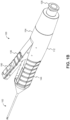
- FIGS. 1A-1C illustrate various views of an example medical instrument 100 that may employ principles of this disclosure.
- FIG. 1A is a side view of the instrument 100 in a configuration with a removable syringe attached.
- FIG. 1B is an isometric view of the instrument 100 in a configuration without the removable syringe and with a connector exposed.
- FIG. 1C is a side view of the instrument 100 in a configuration with a removable cap attached.
- the instrument 100 generally includes a tool section 102 and a handle 104.
- the handle 104 is configured to interface with a fluid source 108, and the instrument 100 is generally configured to deliver fluid to a target site.
- the instrument 100 may be configured to deliver fluid from the fluid source 108, through the handle 104, and through the tool section 102 to a target site of the patient upon actuating a fluid transfer mechanism in the handle 104.
- the instrument 100 may be configured to transfer fluid through a channel in the handle 104 upon depressing a plunger 120 ( e.g., via force applied by a finger to the proximal end of the plunger) or otherwise ejecting fluid from the fluid source 108.
- the handle 104 includes a housing 112 having a connector or interface for coupling to the fluid source 108. More particularly, the housing 112 includes a luer lock connector 128 configured to removably attach to a component of the fluid source 108, such as a syringe 124 and/or a pre-fill component 300 ( FIGS. 5A-5G ) that contains a fluid compartment (e.g ., a barrel) for holding a desired liquid or substance. As appropriate, the syringe 124 may be attached or removed from the housing 112 via the luer lock connector 128 through rotational or twisting motion between the housing 112 and the syringe 124.
- a component of the fluid source 108 such as a syringe 124 and/or a pre-fill component 300 ( FIGS. 5A-5G ) that contains a fluid compartment (e.g ., a barrel) for holding a desired liquid or substance.
- the syringe 124 may be attached or removed from
- the syringe 124 is implemented as a viscoelastic syringe for holding a viscoelastic fluid or substance of a type useful for ophthalmic procedures.
- the instrument 100 may be designed to handle cohesive, dispersive, or both cohesive and dispersive viscoelastic materials. Additionally or alternatively, the instrument 100 may be compatible with other fluids (e.g. , saline, medicinal liquids, etc.) suitable for a variety of ocular or other medical procedures.
- the instrument may be further provided with a removable cap 132 that attaches to the housing 112 via the luer lock connector 128, and which may, for example, serve to protect or isolate components of the instrument during transport or periods of non-use.
- a luer lock connector 128 any of a variety of other standard or non-standard connectors may be included for fluidic coupling, as appropriate.
- the handle 104 or the housing 112 may additionally or alternatively be provided with an integral fluid compartment for holding a desired fluid. More generally, in various embodiments the tool section 102, handle 104, and fluid source 108 may be removably attached, or any two or more of these components may be integrally formed or provided as a single unit.
- FIGS. 2A-2B are illustrations showing example modes of operating the instrument 100.
- the handle 104 is equipped with a button 136 that may be used to actuate a fluid transfer mechanism.
- the button 136 may be configured to deliver a dosage of fluid from the syringe 124 through actuation of a fluid transfer mechanism employed in the handle 104.
- the housing 112 may have a shape that permits gripping of the instrument by a human hand 140 or otherwise permits manipulation of the surgical instrument by an operator.
- the housing 112 may be configured as an elongate tubular or cylindrical member that permits grasping of the instrument, which facilitates precise control over incisions made with the tool section 102 or accurate insertion of the tool section 102 into a fluid injection site of a patient.
- An exterior surface or lateral side of the housing 112 further includes grip-enhancing features 144, including a contoured profile and a series of ring indentations.
- the button 136 is disposed on a lateral side of the handle 104.
- the button 136 is disposed on a lateral side of the housing 112. This may facilitate pressing of the button 136 with ease or without a need for repositioning of the instrument 100 using a digit of the hand 140 while the instrument is manipulated using a grip that also facilitates precise control.
- the button 136 may be positioned in a user's hand 140 for actuation using a thumb 152.
- the button 136 may be positioned in a user's hand 140 for actuation using an index finger 148.
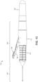
- FIG. 3 is a side view cross section of the instrument 100 illustrating components of a fluid transfer mechanism in detail.
- FIG. 3 shows the handle 104 of the instrument 100 with a removable cap 132 attached and with the tool section 102 attached.
- the housing 112 is shown as being composed of several pieces rigidly fixed together, but in other embodiments, the housing 112 may be composed of one integral piece.
- the housing 112 may be made from any of a variety of suitable materials, such as plastics, metals, and the like.
- the fluid transfer mechanism includes a piston 156 disposed in an interior of the housing 112.
- the piston 156 is generally configured to move relative to the housing 112, and more particularly, is configured to reciprocate within the housing for pumping or otherwise transferring fluid.
- the housing 112 is configured as an elongate tubular housing defining a longitudinal axis 160 ( e.g., cylindrical axis), and the piston 156 is configured to reciprocate back and forth within an interior cavity of the housing 112 along the longitudinal axis 160 an axial direction of the housing 112.
- the interior cavity of the housing 112 includes one or more sealed chambers 164a,b that may be implemented as cylinders for compression and expansion by the piston 156. More particularly, the interior cavity of the housing 112 includes a pair of complementary chambers, including a fluid entry chamber 164a and a fluid exit chamber 164b disposed on opposing sides of the piston 156. The chambers are configured in a complementary fashion such that a compression stroke of the piston 156 for one of the chambers corresponds to an expansion stroke for the other chamber, and vice versa.
- the entry chamber 164a may be sealed with an O-ring 168a disposed between a lateral exterior surface of the piston 156 and an interior surface of the cavity.
- the second chamber 164b may be sealed with an O-ring 168b disposed between a lateral exterior surface of the piston 156 and an interior surface of the cavity. More generally, in various embodiments either or both of the chambers 164a,b may be sealed using any of a variety of other appropriate seals or sealing elements.
- the fluid transfer mechanism also generally includes a series of valves 172a-d and a fluidic channel 180 extending through the piston to facilitate compression, expansion, and transfer of the fluid within the mechanism as appropriate.
- the fluid transfer mechanism may be designed to transfer fluid in a forward direction, from a proximal end to a distal end.
- an entry valve 172a is disposed at a fluid entry port of the entry chamber 164a.
- the fluid entry port may be disposed at the position of the luer lock connector 128.
- the entry valve 172a may be fixedly attached to the housing 112 and disposed at a proximal end of the entry chamber 164a.
- the entry valve 172a may be provided as part of the syringe 124 or fluid source 108 (not shown in FIG. 3 ), or the fluid entry port may be disposed in another physical location relative to the entry chamber 164a.
- the entry valve 172a may be a check valve (or one-way valve) of a type that permits fluid flow across it in a direction into the entry chamber 164a but prevents fluid flow across it in a direction out of the entry chamber 164a.
- An exit valve 172b is disposed at a fluid exit port of the exit chamber 164b, which corresponds to the position of the tool section 102 or a tool interface 116 configured to couple to a tool section 102.
- the tool interface 116 can be configured as a luer lock connector for coupling to a removable tool or provide a fixed fastening mechanism (e.g., welding, adhesives, screws, etc.)
- the exit valve 172b may be fixedly attached to the housing 112 and disposed at a distal end of the exit chamber 164b.
- the exit valve 172b may be a check valve of a type that permits fluid flow across it in a direction out of the exit chamber 164b but prevents fluid flow across it in a direction into the exit chamber 164b.
- piston valves 172c,d are disposed on the piston 156 in a fluidic pathway extending through the piston 156.
- the piston 156 includes a channel 180 extending through it for transferring fluid from the entry chamber 164a to the exit chamber 164b, with one or more piston valves 172c,d disposed in the piston channel 180 or otherwise disposed in the fluidic pathway defined by the piston channel 180.
- Each of the piston valves 172c,d may be a check valve (or one-way valve) of a type that permits fluid flow across it in a forward direction, e.g ., towards a distal side or in direction extending from the entry chamber 164a to exit chamber 164b, but prevents fluid flow across it in the opposite direction.
- the piston channel 180 is segmented into a plurality of sub-channels, each terminating in a respective piston valve.
- the piston channel 180 includes a first sub-channel terminating in a first piston valve that feeds fluid into a second sub-channel terminating in a second piston valve, and so forth.
- the piston 156 itself may be segmented into a plurality of components or pieces that are fixedly attached to one another, which may facilitate manufacturing of a piston having multiple piston channels.
- the piston 156 may be a unitary and integral construction.
- a useful metric of a chamber may be a compression ratio (or its inverse, a expansion ratio) corresponding to a ratio of the internal volume of the chamber at is maximum and minimum points, which may correspond to a position of the piston at each end of its stroke.
- the compression ratio or expansion ratio of a chamber may be determined by the location of the valves and diameter of the piston in the chamber. Segmenting the channel may be useful, for example, for increasing or tuning an effective compression and/or expansion ratio of one or more of the chambers for a given interior volume or piston stroke. For example, with reference to FIG.
- the expansion ratio of the entry chamber 164a is made greater by the existence of the piston valve 172c between the piston valve 172d and entry valve 172a, relative to if this piston valve 172c were omitted. Since the internal volume of the sub-channel between piston valves 172c and 172d is essentially held constant during the expansion stroke of the piston 156, this internal volume is effectively removed from the equation. As a result, a greater expansion ratio in the entry chamber 164a, and thus, a greater suction force across the entry valve 172a, may be achieved for a given length of the stroke for the piston.
- adjusting the compression ratio can modify the volume of each dosage provided by the mechanism by changing a volume of fluid held in the exit chamber 164b that is ejected upon actuation of the piston 156.
- a dose adjustment member 139 can be included in the handle 104.
- the dose adjustment member 139 can be, for example, a removable component or a movable component (e.g., slidable, twistable, etc.) that is configured to permit adjustment of the compression ratio.
- the dose adjustment member 139 may be a removable component in the interior cavity of the housing 112 that can be swapped by a user or during manufacturing to tune the length of travel of the piston to adjust the compression ratio, and thereby the dosage delivered at each piston stroke or button press.
- the dose adjustment member 139 can be coupled to a user interface components, such as a slider or twist mechanism on the handle, that is configured to move the dose adjustment member 139 to various positions along the inner cavity of the housing 112 to constrain the travel of the piston to change the length of the piston stroke to two or more different user defined dosage volumes.
- a user interface components such as a slider or twist mechanism on the handle
- the fluid transfer mechanism may further include or otherwise cooperate with a button 136.
- the button 136 is implemented as a mechanical button that is coupled to the piston 156 and configured to generate axial motion of the piston 156.
- the button 136 includes an engagement member 176a coupled to a corresponding engagement member 176b of the piston 156.
- the engagement members 176a, 176b can be, for example, sloped surfaces and/or wheels that are configured to engage each other to drive motion of the piston upon depression of the button 136.
- the engagement member 176a of the button 136 can be a sloped surface, such as a ramp disposed on an interior surface of the button 136, while the engagement member 176b of the piston can be a complementary sloped surface, such as a ramp disposed on an exterior surface of the piston 156. Sliding engagement between the corresponding sloped surfaces may generate axial motion of the piston 156, as the button is depressed to convert depression of the button to distal motion of the piston.
- one of the button or the piston can include a sloped surface and the other of the button or the piston can include a wheel to facilitate engagement by rolling contact between the button and the piston that drives the motion of the piston upon depression of the button.
- Such a rolling engagement mechanism may reduce friction to facilitate smoother operation and actuation by the user.
- the engagement member 176a of the button 136 includes a sloped surface
- the engagement member 176b of the piston includes a wheel.
- these engagement members can be switched so that the button includes a wheel and the piston includes a sloped surface, for example.
- the button 136 is also pivotally attached to the housing 112 via a hinge 184, which may permit sliding or rolling engagement between the corresponding engagement members as the button 136 pivots about the hinge 184.
- the piston 156 is biased to a position at an end of its stroke. This may also bias the button 136 to an upward or release position.
- a return spring 188 is included that biases the piston 156 towards the proximal end of the housing 112.
- the return spring 188 is implemented as a coil spring disposed around a shaft of the piston 156 and coupled between an axial surface of the housing and an axial surface 192 of the piston 156.
- the piston 156 includes a step disposed on its exterior surface, as shown in FIG. 3 .
- a return spring 188 is shown in a particular configuration, it will be appreciated the return spring may be modified or positioned differently, or any of a variety of biasing elements (e.g ., magnets, torsion springs, etc.) may be used to bias the piston 156.
- biasing elements e.g ., magnets, torsion springs, etc.
- the return spring 188 is shown as an axial coil spring abutting axial surfaces of the housing 112 and the piston 156, a similar effect may be achieved by implementing the return spring as a torsion spring in the hinge 184.
- both an axial spring 188 and a torsion spring in the hinge 184 may be used, where the torsion spring returns the button to a non-actuated position more quickly than the axial spring 188 returns the piston to the proximal position, thereby providing for improved user experience. Biasing the button 136 and the piston 156 in this fashion may allow each button press to trigger a single stroke of the piston 156 and, accordingly, dispense a single dosage of fluid via the fluid transfer mechanism.
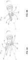
- FIGS. 4A-4B show the instrument 100 in isometric view with portions of the housing 112 removed to allow for viewing of the fluid transfer mechanism in various stages of operation.
- FIG. 4A shows the mechanism with the piston 156 in a backwards and biased position and with the button 136 in an upwards and biased position.
- FIG. 4B shows the mechanism with the piston 156 in a forwards and actuated position and the button 136 in an actuated and depressed position.
- FIGS. 4A-4B also show in more detail an example of how engagement between the button 136 and the piston 156 can generate axial motion of the piston 156. As the button 136 is depressed and moved from the position in FIG. 4A to the position in FIG.
- the piston and button may roll or slide against each other to drive the piston forward.
- the button 136 may further include a groove 194 for accommodating a shaft 198 of the piston and facilitating good contact between the corresponding engagement members 176a,b by permitting the engagement members 176a,b to be positioned around the shaft 198.
- the piston 156 may include one or more wheels 129 that couple the piston to the housing so that the piston can roll along the housing as it translates axially, thereby reducing friction during reciprocating motion of the piston. Additionaly or alternatively, it is contemplated that such the wheel 129 can be positioned on an interior side of the housing 112.
- the instrument 100 may additionally or alternatively employ any of a variety of other actuators, such as other mechanical actuators, electronic actuators, touch sensitive buttons, or the like.
- FIGS. 4A-4B also show a lock mechanism 190 that may be included in or otherwise cooperate with the housing 112 be configured to lock the button 136 down or lock the piston 156 in a forward position.
- the lock mechanism 190 includes a tab 189 on the button 136 that can be slide into a corresponding slot 187 on the housing 112 to hold the button 136 in a depressed position upon moving or sliding the tab. Positioning the moving tab 189 on the button may facilitate ergonomic one-handed operation, allowing the user to depress the button and operate the lock mechanism in one seamless movement.
- the tab is instead included on the housing 112, which can hold the button down with or without a slot on the button (e.g ., the tab can slide on top of the button when the button is depressed to avoid a need for a button slot).
- the lock mechanism 190 can have a stop member disposed on the piston 156 ( e.g., on an exterior surface thereof), a groove for accommodating the stop member when in an unlocked or biased position, and twistable member on the handle that is twistable relative to an axis of the piston 156. Twisting the twistable member may move the lock groove out of position where it can accommodate the stop member and cause the stop member to abut a surface and hold the piston in a forward position.
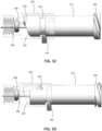
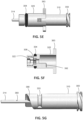
- FIGS. 5A-5G illustrate various views of an example of a pre-fill component 300 that can be included in the medical instrument 100.
- FIG. 5A is a side view and
- FIG. 5B is a longitudinal cross-section view showing the pre-fill component coupled to the handle of the instrument.
- FIGS. 5C-5D are side views of the pre-fill component showing movement of a sliding seal at various stages of operation.
- FIGS. 5E-5G show various views of sub-components of the pre-fill component 300 in unassembled configurations.
- the pre-fill component 300 can contain a pre-fill chamber 330 that provides a fluid compartment from which the fluid transfer mechanism can draw fluid.
- the pre-fill chamber 330 can be filled with a desired fluid by coupling a syringe 124 or other fluid source to the pre-fill component during a priming or initial stage prior to a procedure. The syringe may be then removed once the pre-fill chamber 330 is filled.
- the pre-fill component 300 may be useful to, for example, reduce a total length of the instrument 100 by allowing the fluid transfer mechanism to draw fluid from a smaller sized or lower volume fluid compartment than in configurations where the syringe or other larger fluid source is maintained attached to the device during a medical procedure.
- the pre-fill component 300 can have a chamber body 340 that is coupled to the handle 104 and to the fluid transfer mechanism via an interface such as luer lock connector 128.
- the pre-fill component 300 can be coupled to the housing 112 via luer lock connector 128 in a manner similar to how the syringe 124 can be coupled to the luer lock connector 128 in embodiments where the syringe 124 is directly coupled to the handle ( e.g ., as seen in FIG. 1A ) .
- the pre-fill chamber body 340 may be an integral part of the handle 104 or may otherwise be fixedly coupled to the handle.
- the pre-fill component 300 can also include another luer connector 350 ( e.g., at a proximal end thereof) for connecting to the syringe 124 or other fluid source that is used to fill the pre-fill component with the desired volume of fluid.
- the syringe 124 may be attached to the pre-fill component 300 via luer connector 350, and the plunger 120 of the syringe may be depressed to first fill the pre-fill chamber 330 with a volume of fluid. Further depression of the plunger 120 may be used to bypass the mechanism as described above ( e.g. , to fully prime the instrument).
- the pre-fill component 300 includes a mechanism to maintain a seal within the pre-fill chamber 330 upon removal of the syringe.
- the mechanism may be useful to, for example, avoid the potential introduction of air bubbles within the chamber or mitigate other undesirable effects upon removal of the syringe.
- FIGS. 5C-5D illustrate an operation of the mechanism of the pre-fill component 300 before and after detachment of a fluid source, such as syringe 124 (detached syringe not visible in FIGS. 5C-5D ).
- FIGS . 5E-5G show various sub-components of the pre-fill component 300 that can be used to fill and seal the pre-fill chamber 330. These sub-components are also shown in various assembled configurations in FIGS. 5A-5D .
- the pre-fill component 300 can include a sealing member 320 and an interface member 310.
- the sealing member 320 is configured to seal the pre-fill chamber 330 and permit the pre-fill chamber 330 to be filled via a fill port 360 of the interface member 310.
- the interface member 310 provides an interface between the pre-fill chamber 330 and the syringe used to fill the pre-fill chamber, which can be attached to the connector 350 of the interface member 310.
- the mechanism can be positioned as shown in FIG. 5C (and FIG. 5B ) during delivery of fluid into the pre-fill chamber 330, where the fill port 360 is in fluid communication with the pre-fill chamber 330.
- the mechanism can be configured to then move the interface member 310 and the sealing member 320 apart from each other upon detachment of the syringe, to isolate the fill port 360 from the pre-fill chamber 330, as shown in FIG. 5D .
- the pre-fill component 300 can be configured as follows to facilitate isolation of the fill port 360.
- the sealing member 320 can be slidably disposed in the chamber body 340, such that it can translate axially along a longitudinal axis thereof (which can correspond to the longitudinal axis 160 of the handle).
- the sealing member 320 can be configured to seal the chamber, for example, via an outer O-ring 304. that is coupled between an outer surface of the sealing member 320 and an inner surface of the chamber body 340.
- the outer O-ring 304 can be fixed to an outer surface of the sealing member 320 or the inner surface of the chamber body 340.
- the sealing member 320 can also be rotatably fixed with respect to the chamber body 340 and the handle.
- the sealing member 320 can include one or more anti-rotation tabs 363, which can protrude radially outward from the sealing member 320.
- the anti-rotation tabs 363 can be slotted in longitudinal slots of the chamber body 340 to constrain rotational movement of the anti-rotation tabs 363 about the longitudinal axis against the longitudinal slots, while permitting axial translation of the anti-rotation tabs 363 along the longitudinal slots. It will be appreciated that this configuration can be reversed, such that the anti-rotation tabs 363 are included on the chamber body and protrude radially inward into longitudinal slots of the sealing member 320.
- Various other mechanisms can be used to constrain the movement as desired.
- the interface member 310 includes the connector 350 at its proximal end for coupling to the fluid source, and a projection 314 at its distal end that extends through an opening in the sealing member 320.
- the fill port 360 is disposed on the projection 314, and configured as a side port positioned on a lateral side of the projection 314 proximal to the terminal end at the distalmost end of the projection 314.
- This configuration allows an inner O-ring 308, disposed between an inner surface of the sealing member 320 and an outer surface of the projection 314, to pass over the fill port 360 with relative movement between the sealing member 320 and the interface member 310, thereby sealing the fill port 360 from the pre-fill chamber 330 or permitting the fill port 360 to fluidly communicate with the pre-fill chamber 330 depending on the relative positions of the sealing member 320 and interface member 310.
- the fill port 360 can be coupled to the luer connector 350 via a lumen 311 extending partially through the interface member 310.
- the inner O-ring can, for example, be held in place via a hollow set screw 322 of the sealing member, located on a distal side of the inner O-ring 308, which can permit the projection 314 to extend therethrough.
- any other suitable mechanism can be used to hold the inner O-ring in place, such as, for example, a circumferential groove along the inner surface of the sealing member 320.
- the interface member 310 can be translatably fixed relative to the handle and chamber body via a retention groove 333.
- a guide member 343, such as a set screw, can be positioned in the retention groove 333, and the retention groove can be configured as a circumferential groove on an outer surface of the interface member 310 to permit the rotation of the interface member 310 as the guide member slides along the circumferential groove.
- the retention groove 333 can have stops positioned at ends thereof that permit rotation of the interface member 310 within only a limited range of motion, such as 180 degrees, which corresponds to half of a circumference of the outer surface of the interface member 310, but prevent rotation of the interface member beyond that limited range of motion upon the guide member 343 abutting the stop at the end of the groove. It will be appreciated that this can be tuned to any other limited range of rotation desired.
- sealing member 320 and the interface member 310 include complementary spiral ramps 390, 392, which are configured to mate with each other.
- sealing member 320 can include a first spiral ramp 392 facing a proximal direction
- the interface member 310 can include a second spiral ramp 390 facing a distal direction.
- the mating spiral ramps are configured to urge the interface member 310 and the sealing member 320 apart from each other with relative rotation therebetween, thereby sliding the inner O-ring over the fill port 360 to isolate the fill port 360 from the pre-fill chamber.
- the longitudinal translation constraint of the interface member coupled with the rotational constraint of the sealing member 320 causes the spiral ramp 390 of the interface member 310 to drive the sealing member 320 in a distal direction to thereby slide the inner O-ring 308 over the fill port 360, as seen in FIG. 5D .
- An operation of the pre-fill component may thus be as follows.
- a user may attach a syringe to the luer connector 350 of the interface member 310, by rotating the syringe about the longitudinal axis in a first direction (e.g. , clockwise).
- the guide member 343 may abut against a first stop at a first end of the circumferential retention groove 333 to permit the syringe to be tightened against the luer connector 350 as it is rotated in the first direction.
- the user may depress the plunger of the syringe to deliver fluid into the pre-fill chamber 330 through the luer connector.
- the user may further depress the plunger to prime the fluid transfer mechanism downstream from the pre-fill chamber after the pre-fill chamber has been filled, where depression of the plunger bypasses the check valves in the fluid transfer mechanism.
- the user may begin to remove the syringe by rotating the syringe in a second direction, opposite the first direction (e.g ., counter-clockwise).
- the rotation to remove the syringe may have two phases.
- the interface member 310 rotates together with the syringe, as the guide member slides along the retention groove away from the first stop, along the groove, and towards the second step.
- the spiral ramp 392 of the interface member urges movement of the sealing member 320 distally along the longitudinal axis, causing the interface member 310 and the sealing member 320 to separate from each other until the inner O-ring 308 slides past the fill port 360 to isolate the fill port 360 from the pre-fill chamber 330, and thus isolate the pre-fill chamber 330 from the syringe.
- the seal between the syringe and the luer connector 350 remains intact and no air is introduced into the device.
- the interface member 310 After the inner O-ring passes over the fill port 360, the interface member 310 reaches the end of its limited rotational travel as the guide member 343 abuts the second stop at the opposite end of the retention groove 333 from the first stop. After this, the second phase of rotation is reached. During this second phase, the further rotation of the syringe disconnects the syringe from the luer connector 350 of the interface member, as the interface member is constrained from further rotation by the second stop. As the fill port 360 is now isolated from the pre-fill chamber, any air introduced by the disconnection of the syringe is prevented from reaching the pre-fill chamber.
- the user may operate the fluid transfer mechanism to deliver doses of fluid from the pre-fill chamber.
- the sealing member 320 may operate as a plunger at this stage, where each dosage of fluid caused by actuating the button draws the sealing member 320 forward distally by an amount of one dosage volume unit.
- FIG. 6 shows a process flow and a schematic diagram of the surgical instrument 100 with various details omitted for simplicity.
- valves 172a-d are depicted schematically as open or closed during each stage, with corresponding arrows depicting a direction of fluid flow across the valve where appropriate.
- a user may attach a syringe 124 to the housing 112.
- the syringe 124 may be attached using a luer lock connector or other suitable connection interface, as described above.
- the fluid transfer mechanism is in a steady state and no fluid is flowing through the fluid transfer mechanism.
- a user may prime the instrument 100.
- the plunger 120 of the syringe 124 may be depressed, or fluid 204 may otherwise be ejected from the syringe 124, which may cause a cracking pressure of each of the valves 172a-d to be exceeded and cause fluid to flow through each of the valves 172a-d, and through the entire housing 112, in the forward direction.
- fluid 204 may otherwise be ejected from the syringe 124, which may cause a cracking pressure of each of the valves 172a-d to be exceeded and cause fluid to flow through each of the valves 172a-d, and through the entire housing 112, in the forward direction.
- air bubbles may be removed and the instrument may be primed for fluid delivery to the intended target site, as appropriate.
- a similar process of depressing the plunger 120 may be used to bypass the fluid transfer mechanism and deliver a steady dosage of fluid, as desired.
- a cracking pressure of each of the valves 172a-d may be configured to be exceeded upon a depression of the plunger 120.
- the syringe 124 remains attached to the instrument during the remainder of the procedure to supply the fluid 204 delivered by the piston pump mechanism.
- priming the instrument 100 may fill a pre-fill chamber as described herein. This may allow the syringe 124 to be removed at this stage, as fluid 204 delivered during the procedure via the piston pump mechanism can be drawn from the pre-fill chamber in the remaining steps.
- a user may press the button, or a forward stroke of the piston 156 may be otherwise actuated.
- the entry chamber 164a may expand, generating a pressure differential or suction force across the entry valve 172a that exceeds its cracking pressure and causes fluid to be drawn into the entry chamber 164a from the fluid compartment.
- the exit chamber 164b compresses, causing a cracking pressure of the exit valve 172b to be exceeded and causing fluid to be ejected from the chamber 164b.
- a dosage of viscoelastic fluid or other fluid may be delivered to a blade, or other surgical tool, or otherwise delivered to a target site. Since the piston valves 172c,d restrict entry to only the forward direction, they remain closed during the forward stroke and facilitate compression and expansion of the chambers 164a,b, as described above.
- a user may release the button, or a backward stroke of the piston 156 may be otherwise initiated.
- the exit chamber 164b expands and the entry chamber 164a compresses.
- the piston valves 172c,d open and permit forward fluid flow across them, thus transferring fluid from the entry chamber 164a to the exit chamber 164b as the entry valve 172a and exit valve 172b remain closed. This may return the piston 156 to its biased position where it is ready to deliver another dosage of fluid.
- embodiments disclosed herein may be useful for medical and surgical procedures.
- it may sometimes be desirable to form an incision of a controlled width e.g., an incision that is wider than an incision made by a typical scalpel, cutting blade or needle) in the eye, skin, mucous membrane, tumor, organ or other tissue or a human or animal.
- some surgical procedures require removal of a strip of tissue of a known width from an anatomical location within the body of a patient.
- a goniotomy a device that is operative to cut or ablate a strip of tissue of approximately 2-10 mm in length or more and about 50-230 um in width is inserted into the anterior chamber of the eye and used to remove a full thickness strip of tissue from the trabecular meshwork.
- the trabecular meshwork is a loosely organized, porous network of tissue that overlies a collecting canal known as Schlemm's canal.
- a fluid known as aqueous humor
- aqueous humor flows through the trabecular meshwork, into Schlemm's canal and out of the eye through a series of ducts called collector channels.
- collector channels the drainage of aqueous humor from the eye may be impaired by elevated flow resistance through the trabecular meshwork, thereby resulting in an increase in intraocular pressure.
- the goniotomy procedure can restore normal drainage of aqueous humor from the eye by removing a full thickness segment of the trabecular meshwork, thus allowing the aqueous humor to drain through the open area from which the strip of trabecular meshwork has been removed.
- Embodiments disclosed herein can be used for surgical medicinal intervention.
- the device may be a dual-blade device for cutting the trabecular meshwork ("TM") in the eye.
- the device may have a device tip providing entry into the Schlemm's canal via its size (i.e., for example, between approximately 0.2-0.3 mm width) and a configuration where the entry blade tip ramps upwardly providing a wedge or ramp-like action for cutting the TM.
- the tool section 102 of the device can include a cannula, a microcannula, or dual-blade tool having a lumen for delivering fluid such as, for example those described in U.S. Non-Provisional Application No. 15/791,204, filed on October 23, 2017 , U.S. Non-Provisional Application No. 15/389,328, filed on December 22, 2016 , U.S. Provisional Application No. 62/750,151, filed on October 28, 2018 , or U.S. Non-Provisional Application No. 15/847,770, filed on December 19, 2017 ,
- the tool may be included in the tool section 102 of the instrument 100.
- the tool is illustrated to reveal the dual cutting blades (arrows) as well as the distal point (asterisk) that is designed to pierce the trabecular meshwork ("TM") and enter into the Schlemm's canal.
- the tool is advanced so that the TM moves up the ramp from the distal point toward the dual cutting blades, which then cleanly incise the presented TM.
- the distance between the dual blades is designed to closely match that of the width of the TM across a range of human eyes.
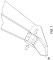
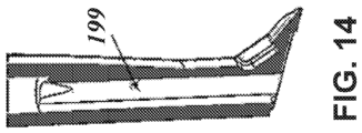
- a device 12 is shown.
- the device 12 may be implemented as an ophthalmic blade that can be included in a distal end of the tool section 102 of the instrument 100 described above.
- the device 12 may further include a lumen 199 that provides a fluidic pathway for delivery or injection of fluid received from a fluid transfer mechanism included in a handle 104.
- a platform 5 of the device 12 can include a tip 6 at a distal side of the platform 5 and a top surface (e.g ., ramp) 13 extending from the distal side of the platform 5 to a proximal side of the platform 5, opposite the distal side of the platform 5.
- the top surface 13 can extend from the tip 6 to one or more lateral elements 10, 11.
- the platform 5 can include a bottom surface 15 extending from the tip 6 at the distal side of the platform 5 to a rear portion 7 of the platform 5, opposite the tip 6.
- the bottom surface 15 of the device 12 can be positioned opposite the top surface 13.
- the bottom surface 15 can be configured to abut the outer wall of the Schlemm's canal during a procedure (see FIGS. 15A-15C ) .
- At least a portion of the bottom surface 15 can be flat and/or planar.
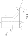
- the rear portion 7 can define a curved or round surface that transitions from the bottom surface 15 to a portion of the shaft 4.
- opposing sides 8, 9 of the platform 5 can extend downwardly from the top surface 13.
- the opposing sides 8, 9 can be planar and/or parallel to each other.
- the top surface 13 can transition to the opposing sides 8, 9 with a transition feature. While a round bevel is shown in FIGS. 8-10 , the transition feature can have one or more other shapes, including curved, round, chamfer, fillet, etc.
- a transition feature can be provided between the bottom surface 15 and the opposing sides 8, 9.
- the bottom surface 15 can transition to the opposing sides 8, 9 with transition sections 28, 29, respectively. While chamfers are shown for transition sections 28, 29 in FIGS. 8-10 , the transition feature can have one or more other shapes, including curved, round, beveled, fillet, etc.
- the width of the device 12 can transition from a first width, between the opposing sides 8, 9, to a second width, less than the first width, across the bottom surface 15. The transition from the first width to the second width can be gradual, linear, stepwise, or another type of transition.
- the bottom surface 15 of the device 12 can include surface features that enhance interactions with the outer wall of the Schlemm's canal during a procedure.
- the bottom surface 15 can be planar, convex, concave, or combinations thereof.
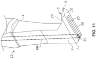
- the bottom surface 15 can include a recessed portion 40 between at least two protrusions.
- the recessed portion 40 can be defined by a gap, space, or void.
- a first protrusion 38 can be positioned below the first side 8 and/or the first transition section 28 of the platform 5.
- the first protrusion 38 can be formed, at least in part, by at least a portion of the first transition section 28.
- a second protrusion 39 can be positioned below the second side 9 and/or the second transition section 29 of the platform 5.
- the second protrusion 39 can be formed, at least in part, by at least a portion of the second transition section 29.
- Each of the protrusions 38, 39 can extend from the rear portion 7 of the platform 5 toward the tip 6.
- the protrusions 38, 39 can be separated by a recessed portion 40 extending there between. As shown in FIGS. 10 and 11 , a transition between the protrusions 38, 39 and the recessed portion 40 can be stepwise, forming one or more edges.
- a transition between the protrusions 38, 39 and the recessed portion 40 can be gradual, curved, round, beveled, chamfered, linear, or another type of transition.
- the recessed portion 40 can include a concave feature. The recessed portion 40 can extend to and intersect the rear portion 7 of the platform 5.
- the bottom surface 15 Adjacent to the tip 6, the bottom surface 15 can provide a continuous (e.g., planar) portion 16 that is not interrupted by the recessed portion 40.
- the tip 6 can be separated from the recessed portion 40 by the continuous portion 16.
- the bottom surface 15 can include a planar distal portion and a non-planar proximal portion along the length thereof.
- the tip 6 and the region ( e.g ., continuous portion 16) immediately proximal to the tip 6 can be continuous, such that the recessed portion 40 does not intersect the tip 6.
- the recessed portion 40 can extend distally from the rear portion 7, for example, not farther than the opposing sides 8, 9 and/or the transition sections 28, 29.
- the recessed portion 40 can terminate on a distal end thereof with a transition feature that is, for example, gradual, curved, round, beveled, chamfered, linear, stepwise, or another type of transition.
- the planar distal portion can provide an even surface to facilitate entry into tissue with the tip 6.
- the nonplanar proximal portion e.g., the protrusions 38, 39 and the recessed portion 40
- the protrusions 38, 39 provide a smaller surface area for exposure to the tissue (e.g ., Schlemm's canal). Accordingly, the nonplanar proximal portion of the bottom surface 15 provides greater maneuverability of the platform 5 as it moves along the tissue.
- FIG. 13 a cross section view of a device similar in some respects to that shown in FIGS. 8-12 is depicted.
- the device further includes an angle (e.g., 4 degrees) on a vertical shaft that allows for a lumen 199 down the shaft.
- an angle e.g., 4 degrees
- the angle between the bottom surface 15 and a back surface of the platform 5 is obtuse, and the back surface is positioned approximately 4 degrees apart relative to a normal of the bottom surface.
- the device is a tool containing an ophthalmic blade of a type similar to those described above with reference to FIGS. 8-13 .
- the device further includes a lumen 199 that may be used for fluid delivery.
- the lumen 199 may be configured to receive viscoelastic fluid from a fluid transfer mechanism and deliver the viscoelastic fluid to a trabecular meshwork or otherwise inject fluid to an intraocular cavity.
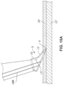
- FIGS. 15A-15D illustrate an example device and a non-claimed method of operation that may be employed in some embodiments of the instrument 100.
- FIGS. 15A-15D show operation of an ophthalmic blade that may be integrated in the tip of the tool section 102 (see, e.g ., FIG. 1 ) and applied to a trabecular meshwork.
- FIGS. 15A-15D also show a lumen 199 that may be used for fluid delivery during the method.
- the device may be introduced through a clear corneal incision on an eye (e.g ., incision size between 0.5 and 2.8 mm in width) and advanced through an anterior chamber of the eye, either across the pupil or across the body of the iris to engage the trabecular meshwork (TM) on the opposite side of the anterior chamber.
- the anterior chamber is filled with aqueous humor and, by way of example, may have a volume of approximately 0.25 milliliter (ml) and be approximately 3 millimeter (mm) deep.
- the anterior chamber may be filled with viscoelastic to replace the aqueous humor and stabilize the chamber during the procedure. Accordingly, approximately 0.25ml may be injected into the chamber at this stage of the surgery.
- the viscoelastic may be injected into the anterior chamber using a syringe.
- the viscoelastic may be injected by depressing plunger 120 or otherwise ejecting fluid from the syringe 124 in a manner that bypasses a fluid transfer mechanism in the instrument 100 (see FIGS. 1-6 ) and causes fluid to flow through the lumen 199.
- actuation of the fluid transfer mechanism e.g ., via button 136) may be used.
- each button press may be configured to deliver only a small single dosage of fluid (e.g ., approximately 0.03 to 0.05 ml of viscoelastic with each button press).
- the bypass mechanism may be useful for allowing the anterior chamber to be initially filled with a larger volume of viscoelastic without a need for a separate syringe. Further, this may allow the fluid transfer to be used later during the procedure to deliver smaller dosages as appropriate, without a need for the surgeon to change their grip during operation.
- the tip 6 of the device may be then used to enter into Schlemm's canal ("SC") 22.
- the ramp 13 may be used to elevate the TM 20 away from the outer wall of the Schlemm's canal 22.
- the advancement of the platform 5 can stretch the TM 20 as it travels up the ramp 13 without tearing a strip 20a of the TM 20 that is on the ramp 13.
- the first side 8 and the second side 9 can allow the TM 20 on the ramp 13 (e.g ., distal to the first and second lateral blades 10, 11) to remain connected to the TM 20 that is not elevated by the ramp 13.
- the TM 20 As the TM 20 is elevated, it is under tension that is greater than the tension of the TM 20 when not elevated from the SC 22.
- Advancement of the ramp 13 facilitates presentation of the TM 20 to the first and second lateral blades 10, 11.
- the TM 20 contacts the first and second lateral blades 10, 11 while the TM 20 is elevated (e.g., stretched and/or under tension).
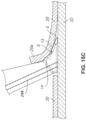
- the first and second lateral blades 10, 11 incise first and second incisions into the TM 20 to form the strip 20a of the TM 20.
- the incision is more easily and precisely made due to the elevation of the TM 20.
- the strip 20a can have a width W that corresponds to the distance D across the gap 14.
- the width W can be measured along the X-axis, such as across the first and second incisions and transversely (e.g., orthogonally) to the direction of advancement of the device 12 to form the strip 20a.
- the distance D can be measured along the X-axis, such as across the first and second lateral blades 10, 11 and transversely (e.g., orthogonally) to the direction of advancement of the device 12 to form the strip 20a.
- the strip 20a that has been separated from a remainder of the TM 20 can be removed by a device 30 (e.g., forceps) or by aspiration.
- bleeding may occur during removal of the TM 20 or during the steps depicted in FIGS. 15B-15C .
- the surgeon may actuate the fluid transfer mechanism (e.g ., press button 136, see FIGS. 1-6 ) to deliver a dosage of viscoelastic. This may push the blood back into the SC 22 or otherwise move the blood away from the TM 20, allowing the surgeon to continue the procedure without a need for removing the device from the anterior chamber to insert a separate viscoelastic syringe.
- the fluid transfer mechanism e.g ., press button 136, see FIGS. 1-6
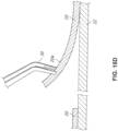
- the advancement of the platform 5 and the ramp 13 can proceed as the device advances clockwise or counterclockwise.
- the distal cutting portion is angled so that the dual blades are placed in optimum cutting position. This angle may be such that the cutting tip bends to conform to the area between Schwalbe's line and the scleral spur (SS), an area that encompasses SC. SC is narrow near the cornea and wider near the SS and thus an angled tip is best to present the tissue 20 to the two edges of the TM.
- the ramp 13 of the cutting tip may be angled so that the tissue 20 is constantly elevated towards the blade as the tip is advanced in circumferential pattern.
- the ramp 13 is shaped to avoid cutting tissue, such that the TM 20 that is elevated away from the outer wall of the Schlemm's canal 22 remains intact as it advances along the ramp 13.
- the ramp 13 can include convex or beveled edges that are not sharp enough to cut the TM 20.
- Endoscopic visualization may also be used to guide the cutting.
- the device of the present disclosure may be placed at the end of an endoscope, precluding the need for a gonio lens during treatment.
- the device of the present disclosure may be place at the end of an endoscope and the TM may be engaged under direct visualization of the endoscope camera.
Landscapes
- Health & Medical Sciences (AREA)
- Life Sciences & Earth Sciences (AREA)
- Engineering & Computer Science (AREA)
- Animal Behavior & Ethology (AREA)
- Veterinary Medicine (AREA)
- Biomedical Technology (AREA)
- Heart & Thoracic Surgery (AREA)
- Public Health (AREA)
- General Health & Medical Sciences (AREA)
- Surgery (AREA)
- Vascular Medicine (AREA)
- Anesthesiology (AREA)
- Hematology (AREA)
- Nuclear Medicine, Radiotherapy & Molecular Imaging (AREA)
- Ophthalmology & Optometry (AREA)
- Medical Informatics (AREA)
- Molecular Biology (AREA)
- Infusion, Injection, And Reservoir Apparatuses (AREA)
Claims (14)
- Medizinisches Instrument (100), aufweisend:ein Gehäuse (112);einen Werkzeugabschnitt (102), der mit dem Gehäuse (112) gekoppelt ist;einen Innenhohlraum, der im Gehäuse (112) angeordnet ist;einen Kolben (156), der im Innenhohlraum angeordnet ist;einen Taster, der mit dem Kolben (156) gekoppelt und am Gehäuse (112) angeordnet ist, wobei der Taster dafür ausgelegt ist, den Kolben (156) zu betätigen, um ein Fluid durch das Gehäuse (112) zu pumpen;dadurch gekennzeichnet, dass es darüber hinauseinen Fluidkanal (180) aufweist, der durch den Kolben (156) verläuft, wobei der Fluidkanal (180) in eine Mehrzahl von Teilkanälen untergliedert ist, wobei jeder der Teilkanäle in einem Ventil (172) endet, wobei ein Fluid, das aus einem ersten der Teilkanäle austritt, dafür ausgelegt ist, in einen zweiten der Teilkanäle eingespeist zu werden.
- Medizinisches Instrument (100) nach Anspruch 1, wobei das Gehäuse (112) ein längliches rohrförmiges Gehäuse (112) mit einer Außenseitenfläche ist, die einen Griff für eine menschliche Hand bereitstellt, und wobei der Taster an einer lateralen Seite des länglichen rohrförmigen Gehäuses (112) angeordnet ist.
- Medizinisches Instrument (100) nach Anspruch 1, wobei der Taster eine erste Schrägfläche aufweist, wobei der Kolben (156) eine zweite Schrägfläche aufweist, und wobei ein Gleiteingriff zwischen der ersten Schrägfläche und der zweiten Schrägfläche dafür ausgelegt ist, einen Hub des Kolbens (156) zu veranlassen.
- Medizinisches Instrument (100) nach Anspruch 1, wobei der Taster oder der Kolben (156) eine Schrägfläche aufweist, wobei das jeweils andere Element, ausgewählt aus Taster und Kolben (156), ein Rad (129) aufweist, und wobei ein Eingriff zwischen der Schrägfläche und dem Rad (129) dafür ausgelegt ist, einen Hub des Kolbens (156) zu veranlassen.
- Medizinisches Instrument (100) nach Anspruch 1, darüber hinaus aufweisend:eine Kammer (164), die im Innenhohlraum angeordnet ist;einen Fluidanschluss, der mit der Kammer (164) gekoppelt ist;ein erstes Ventil (172a), das am Fluidanschluss angeordnet ist; undein zweites Ventil (172b), das am Kolben (156) angeordnet ist.
- Medizinisches Instrument (100) nach Anspruch 1, darüber hinaus aufweisend:eine erste Kammer (164a), die im Innenhohlraum auf einer ersten Seite des Kolbens (156) angeordnet ist; undeine zweite Kammer (164b), die im Innenhohlraum auf einer zweiten Seite des Kolbens (156), entgegengesetzt zur ersten Seite des Kolbens (156), angeordnet ist,wobei ein Vorwärtshub des Kolbens (156) eine Kompression der ersten Kammer (164a) und eine Ausdehnung der zweiten Kammer (164b) bewirkt.
- Medizinisches Instrument (100) nach Anspruch 6,wobei die Kompression der ersten Kammer (164a) dafür ausgelegt ist, ein Fluid aus der ersten Kammer (164a) zum Werkzeugabschnitt (102) auszustoßen, undwobei die Ausdehnung der zweiten Kammer (164b) dafür ausgelegt ist, ein Fluid von einer Fluidquelle (108) in die zweite Kammer (164b) zu saugen.
- Medizinisches Instrument (100) nach Anspruch 1,wobei das Gehäuse (112) ein längliches rohrförmiges Gehäuse (112) mit einem distalen Ende und einem proximalen Ende ist;wobei der Werkzeugabschnitt (102) am distalen Ende des Gehäuses (112) angeordnet ist;wobei ein Fluidverbinder am proximalen Ende des Gehäuses (112) angeordnet ist;wobei eine Fluidaustrittskammer (164b) im Innenhohlraum auf einer distalen Seite des Kolbens (156) angeordnet ist; undwobei eine Fluideintrittskammer im Innenhohlraum auf einer proximalen Seite des Kolbens (156) angeordnet ist.
- Medizinisches Instrument (100) nach Anspruch 1,wobei der Werkzeugabschnitt (102) eine ophthalmische Klinge an einem distalen Ende und ein Lumen aufweist;wobei das Gehäuse (112) dafür ausgelegt ist, mit einer viskoelastischen Spritze gekoppelt zu werden; undwobei der Kolben (156) dafür ausgelegt ist, ein viskoelastisches Fluid von der viskoelastischen Spritze zum Lumen zu befördern.
- Medizinisches Instrument (100) nach Anspruch 9,
wobei die ophthalmische Klinge eine Doppelklingenspitze zum Einschneiden in ein Trabekelwerk aufweist. - Medizinisches Instrument (100) nach Anspruch 1, darüber hinaus aufweisend:ein Vorfüllkammer (330);ein Dichtungselement (320), das dafür ausgelegt ist, die Vorfüllkammer (330) abzudichten; undein Schnittstellenelement (310) mit einem proximalen Ende, das dafür ausgelegt ist, mit einer Fluidquelle (108) gekoppelt zu werden, einem distalen Ende, das dafür ausgelegt ist, durch das Dichtungselement (320) zu verlaufen, und einem Füllanschluss (360), der dafür ausgelegt ist, der Vorfüllkammer (330) ein Fluid von der Fluidquelle (108) zuzuführen,wobei eine Drehung des Schnittstellenelements (310) relativ zum Dichtungselement (320) dafür ausgelegt ist, eine Bewegung des Dichtungselements (320) zur Isolierung des Füllanschlusses (360) von der Vorfüllkammer (330) anzutreiben.
- Medizinisches Instrument (100) nach Anspruch 1, darüber hinaus aufweisend:eine Vorfüllkammer (330);ein Dichtungselement (320), das dafür ausgelegt ist, die Vorfüllkammer (330) abzudichten, wobei das Dichtungselement (320) entlang einer Längsachse des Gehäuses (112) verschiebbar und mit Bezug auf das Gehäuse (112) drehfest ist, wobei das Dichtungselement (320) eine Öffnung hat, die durch es hindurch verläuft, und ein erste Spiralrampe (392); undein Schnittstellenelement (310) mit einem proximalen Ende, einem distalen Ende, einem Verbinder am proximalen Ende, der dafür ausgelegt ist, mit einer Fluidquelle (108) gekoppelt zu werden, einem Vorsprung am distalen Ende, der durch die Öffnung des Dichtungselements (320) verläuft, ein Füllanschluss (360) auf einer lateralen Seite des Vorsprungs, und einer zweiten Spiralrampe (390), die dafür ausgelegt ist, mit der ersten Spiralrampe (392) des Dichtungselements (320) zusammenzupassen, wobei das Schnittstellenelement (310) um die Längsachse des Gehäuses (112) innerhalb eines begrenzten Drehbereichs drehbar ist, und entlang der Längsachse mit Bezug auf das Gehäuse (112) translatorisch fixiert ist,wobei eine Drehung des Schnittstellenelements (310) innerhalb des begrenzten Bereichs dafür ausgelegt ist, das Dichtungselement (320) über einen Eingriff zwischen der ersten und zweiten Spiralrampe (390, 392) distal entlang der Längsachse anzutreiben, um eine Dichtung am Füllanschluss (360) vorbeizuschieben, um den Füllanschluss (360) von der Vorfüllkammer (330) zu isolieren.
- Medizinisches Instrument (100) nach Anspruch 1, darüber hinaus ein Dosiseinstellelement (139) aufweisend, das mit dem Kolben (156) gekoppelt ist, wobei das Dosiseinstellelement (139) verstellbar ist, um einen des Kolbens (156) zu modifizieren und dadurch ein bei einem Vorwärtshub des Kolbens (156) zugeführtes Volumen des Fluids zu ändern.
- Medizinisches Instrument (100) nach Anspruch 1, darüber hinaus aufweisend:
einen Verriegelungsmechanismus (190), der dafür ausgelegt ist, den Kolben (156) in einer Vorwärtsposition zu verriegeln, wobei der Verriegelungsmechanismus (190) ein Anschlagelement am Kolben (156) und ein verdrehbares Element aufweist, das dafür ausgelegt ist, sich am Anschlagelement abzustützen, oder wobei der Verriegelungsmechanismus (190) eine Lasche (189) am Taster aufweist, die in das Gehäuse (112) geschoben werden kann, um den Taster in einer gedrückten Position zu halten.
Priority Applications (1)
| Application Number | Priority Date | Filing Date | Title |
|---|---|---|---|
| EP23156044.2A EP4197502A1 (de) | 2018-04-12 | 2019-04-12 | Vorrichtung und verfahren zur intraokularen flüssigkeitsinjektion |
Applications Claiming Priority (2)
| Application Number | Priority Date | Filing Date | Title |
|---|---|---|---|
| US201862656818P | 2018-04-12 | 2018-04-12 | |
| PCT/US2019/027358 WO2019200336A1 (en) | 2018-04-12 | 2019-04-12 | Device and method for intraocular fluid injection |
Related Child Applications (2)
| Application Number | Title | Priority Date | Filing Date |
|---|---|---|---|
| EP23156044.2A Division-Into EP4197502A1 (de) | 2018-04-12 | 2019-04-12 | Vorrichtung und verfahren zur intraokularen flüssigkeitsinjektion |
| EP23156044.2A Division EP4197502A1 (de) | 2018-04-12 | 2019-04-12 | Vorrichtung und verfahren zur intraokularen flüssigkeitsinjektion |
Publications (2)
| Publication Number | Publication Date |
|---|---|
| EP3773375A1 EP3773375A1 (de) | 2021-02-17 |
| EP3773375B1 true EP3773375B1 (de) | 2023-04-12 |
Family
ID=66323980
Family Applications (2)
| Application Number | Title | Priority Date | Filing Date |
|---|---|---|---|
| EP19720301.1A Active EP3773375B1 (de) | 2018-04-12 | 2019-04-12 | Vorrichtung zur intraokularen fluidinjektion |
| EP23156044.2A Pending EP4197502A1 (de) | 2018-04-12 | 2019-04-12 | Vorrichtung und verfahren zur intraokularen flüssigkeitsinjektion |
Family Applications After (1)
| Application Number | Title | Priority Date | Filing Date |
|---|---|---|---|
| EP23156044.2A Pending EP4197502A1 (de) | 2018-04-12 | 2019-04-12 | Vorrichtung und verfahren zur intraokularen flüssigkeitsinjektion |
Country Status (5)
| Country | Link |
|---|---|
| US (3) | US10946145B2 (de) |
| EP (2) | EP3773375B1 (de) |
| JP (1) | JP7417535B2 (de) |
| CN (1) | CN112312868B (de) |
| WO (1) | WO2019200336A1 (de) |
Families Citing this family (6)
| Publication number | Priority date | Publication date | Assignee | Title |
|---|---|---|---|---|
| CA2868341C (en) | 2012-03-26 | 2021-01-12 | Glaukos Corporation | System and method for delivering multiple ocular implants |
| US11925578B2 (en) | 2015-09-02 | 2024-03-12 | Glaukos Corporation | Drug delivery implants with bi-directional delivery capacity |
| US11439537B2 (en) | 2020-04-10 | 2022-09-13 | Paul Phillips | Opthalmic cannulated wound-stabilizing blade and method of using same |
| JP2023526316A (ja) * | 2020-05-11 | 2023-06-21 | グローコス コーポレーション | 眼の流路への流体の送達 |
| DE102020115489A1 (de) | 2020-06-10 | 2021-12-16 | Carl Zeiss Meditec Ag | Injektoranordnung für ein Einführen einer Intraokularlinse und Injektor |
| US20230293347A1 (en) | 2022-03-16 | 2023-09-21 | Sight Sciences, Inc. | Devices and methods for intraocular tissue manipulation |
Family Cites Families (31)
| Publication number | Priority date | Publication date | Assignee | Title |
|---|---|---|---|---|
| US3797488A (en) * | 1972-07-10 | 1974-03-19 | Ampoules Inc | Ampoule applicator with one-way clutch |
| US5176645A (en) * | 1991-05-01 | 1993-01-05 | Diana Corporation | Pneumatic, modular device for dispensing medication to animals |
| DE9107574U1 (de) * | 1991-06-20 | 1991-08-01 | Bayer Ag, 5090 Leverkusen, De | |
| US7708711B2 (en) * | 2000-04-14 | 2010-05-04 | Glaukos Corporation | Ocular implant with therapeutic agents and methods thereof |
| US6638239B1 (en) | 2000-04-14 | 2003-10-28 | Glaukos Corporation | Apparatus and method for treating glaucoma |
| CA2528280C (en) * | 2003-06-10 | 2012-12-11 | Neomedix Corporation | Tubular cutter device for cutting and removing strips of tissue from the body of a patient |
| BRPI0506837A (pt) * | 2004-01-12 | 2007-06-12 | Iscience Surgical Corp | injetor para materiais viscosos, e, dispositivos e kit para fornecer microquantidades de materiais viscosos |
| JP4468002B2 (ja) * | 2004-02-02 | 2010-05-26 | 壽印刷紙工株式会社 | サイドノック式繰出し機構 |
| AU2005259265A1 (en) * | 2004-07-05 | 2006-01-12 | Novo Nordisk A/S | A credit card sized injection device |
| US20060047250A1 (en) * | 2004-08-30 | 2006-03-02 | Hickingbotham Dyson W | Fluid delivery device |
| CN1313053C (zh) * | 2004-09-15 | 2007-05-02 | 施迎敢 | 针尖回缩型一次性安全采血针及一次发射型安全采血笔 |
| US7226435B2 (en) * | 2004-10-14 | 2007-06-05 | Alcon, Inc. | Drug delivery device |
| AU2006247123A1 (en) * | 2005-05-18 | 2006-11-23 | Surmodics, Inc. | Insertion instrument for non-linear medical devices |
| EP2033577A4 (de) * | 2006-06-13 | 2011-09-07 | Izumi Cosmo Co Ltd | Lanzettenanordnung |
| CN201088780Y (zh) * | 2007-09-05 | 2008-07-23 | Amsino医疗集团控股有限公司 | 单向正压阀 |
| CN102307604B (zh) * | 2009-02-07 | 2016-02-10 | 美国医疗设备有限公司 | 带阀连接器 |
| US9101739B2 (en) * | 2009-02-17 | 2015-08-11 | Entellus Medical, Inc. | Balloon catheter inflation apparatus and methods |
| CN107348981B (zh) * | 2011-10-26 | 2020-11-10 | 直观外科手术操作公司 | 具有整体的手术刀刀片的外科手术器械 |
| WO2013078173A2 (en) * | 2011-11-22 | 2013-05-30 | Mallinckrodt Llc | Hand-actuated fluid delivery device |
| EP2844200B1 (de) * | 2012-03-20 | 2020-11-25 | Sight Sciences, Inc | Okulare freisetzungssysteme |
| US9421129B2 (en) * | 2012-04-02 | 2016-08-23 | Ocuject, Llc | Intraocular delivery devices and methods therefor |
| KR101290512B1 (ko) * | 2012-08-22 | 2013-07-26 | 장택희 | 주사바늘 인출길이 조절이 가능한 안전주사기 |
| CN116327482A (zh) * | 2013-05-03 | 2023-06-27 | 科尼尔赛德生物医学公司 | 用于眼部注射的设备和方法 |
| EP3082909A1 (de) * | 2013-12-20 | 2016-10-26 | Novo Nordisk A/S | Mechanische anzeige für ausgestossene dosis |
| US10258502B2 (en) * | 2014-09-18 | 2019-04-16 | Orbit Biomedical Limited | Therapeutic agent delivery device |
| CN107249522B (zh) * | 2014-09-19 | 2021-04-20 | 奥叙拉尔有限公司 | 眼科递送装置 |
| US10195415B2 (en) * | 2015-09-21 | 2019-02-05 | Carefusion 303, Inc. | Priming device |
| BR112018012876A2 (pt) * | 2015-12-23 | 2018-12-04 | New World Medical Inc | bisturi oftálmico e métodos de uso |
| CN205581650U (zh) * | 2016-02-29 | 2016-09-14 | 蒋尚葵 | 运动传递结构 |
| JP6969876B2 (ja) * | 2016-02-29 | 2021-11-24 | メディセル・アーゲー | 伝動機構、特に歯車列を有するインジェクタ |
| CN105832460A (zh) * | 2016-03-07 | 2016-08-10 | 张友岩 | 一种眼科注射器 |
-
2019
- 2019-04-12 EP EP19720301.1A patent/EP3773375B1/de active Active
- 2019-04-12 WO PCT/US2019/027358 patent/WO2019200336A1/en active Application Filing
- 2019-04-12 EP EP23156044.2A patent/EP4197502A1/de active Pending
- 2019-04-12 JP JP2020555392A patent/JP7417535B2/ja active Active
- 2019-04-12 CN CN201980039823.6A patent/CN112312868B/zh active Active
- 2019-12-06 US US16/706,538 patent/US10946145B2/en active Active
-
2021
- 2021-02-26 US US17/187,110 patent/US11844934B2/en active Active
-
2023
- 2023-11-16 US US18/511,668 patent/US20240082500A1/en active Pending
Also Published As
| Publication number | Publication date |
|---|---|
| US20200108207A1 (en) | 2020-04-09 |
| US10946145B2 (en) | 2021-03-16 |
| WO2019200336A1 (en) | 2019-10-17 |
| EP4197502A1 (de) | 2023-06-21 |
| CN112312868A (zh) | 2021-02-02 |
| JP7417535B2 (ja) | 2024-01-18 |
| US11844934B2 (en) | 2023-12-19 |
| CN112312868B (zh) | 2023-12-22 |
| US20240082500A1 (en) | 2024-03-14 |
| US20210178081A1 (en) | 2021-06-17 |
| EP3773375A1 (de) | 2021-02-17 |
| JP2021520883A (ja) | 2021-08-26 |
Similar Documents
| Publication | Publication Date | Title |
|---|---|---|
| EP3773375B1 (de) | Vorrichtung zur intraokularen fluidinjektion | |
| JP7162044B2 (ja) | 眼科ナイフ及び使用方法 | |
| US11844727B2 (en) | Ophthalmic knife and methods of use | |
| WO2017087713A1 (en) | Delivery device systems and implants for treating glaucoma | |
| US11504270B1 (en) | Ocular delivery systems and methods | |
| JP2022505839A (ja) | 眼科デバイス | |
| US7879006B2 (en) | Injection aid for anterior juxtascleral depot | |
| KR20230130622A (ko) | 점탄성 전달을 위한 시스템 및 방법 | |
| CN111405874B (zh) | 用于双切口的眼内装置 | |
| US20240041646A1 (en) | Ophthalmic device | |
| WO2021113399A9 (en) | An ophthalmic knife | |
| US20210212859A1 (en) | Intraocular device for dual incisions |
Legal Events
| Date | Code | Title | Description |
|---|---|---|---|
| STAA | Information on the status of an ep patent application or granted ep patent |
Free format text: STATUS: UNKNOWN |
|
| STAA | Information on the status of an ep patent application or granted ep patent |
Free format text: STATUS: THE INTERNATIONAL PUBLICATION HAS BEEN MADE |
|
| PUAI | Public reference made under article 153(3) epc to a published international application that has entered the european phase |
Free format text: ORIGINAL CODE: 0009012 |
|
| STAA | Information on the status of an ep patent application or granted ep patent |
Free format text: STATUS: REQUEST FOR EXAMINATION WAS MADE |
|
| 17P | Request for examination filed |
Effective date: 20201026 |
|
| AK | Designated contracting states |
Kind code of ref document: A1 Designated state(s): AL AT BE BG CH CY CZ DE DK EE ES FI FR GB GR HR HU IE IS IT LI LT LU LV MC MK MT NL NO PL PT RO RS SE SI SK SM TR |
|
| AX | Request for extension of the european patent |
Extension state: BA ME |
|
| DAV | Request for validation of the european patent (deleted) | ||
| DAX | Request for extension of the european patent (deleted) | ||
| GRAP | Despatch of communication of intention to grant a patent |
Free format text: ORIGINAL CODE: EPIDOSNIGR1 |
|
| STAA | Information on the status of an ep patent application or granted ep patent |
Free format text: STATUS: GRANT OF PATENT IS INTENDED |
|
| INTG | Intention to grant announced |
Effective date: 20221021 |
|
| GRAS | Grant fee paid |
Free format text: ORIGINAL CODE: EPIDOSNIGR3 |
|
| GRAA | (expected) grant |
Free format text: ORIGINAL CODE: 0009210 |
|
| STAA | Information on the status of an ep patent application or granted ep patent |
Free format text: STATUS: THE PATENT HAS BEEN GRANTED |
|
| AK | Designated contracting states |
Kind code of ref document: B1 Designated state(s): AL AT BE BG CH CY CZ DE DK EE ES FI FR GB GR HR HU IE IS IT LI LT LU LV MC MK MT NL NO PL PT RO RS SE SI SK SM TR |
|
| REG | Reference to a national code |
Ref country code: GB Ref legal event code: FG4D |
|
| REG | Reference to a national code |
Ref country code: CH Ref legal event code: EP |
|
| REG | Reference to a national code |
Ref country code: DE Ref legal event code: R096 Ref document number: 602019027463 Country of ref document: DE |
|
| REG | Reference to a national code |
Ref country code: IE Ref legal event code: FG4D |
|
| REG | Reference to a national code |
Ref country code: AT Ref legal event code: REF Ref document number: 1559393 Country of ref document: AT Kind code of ref document: T Effective date: 20230515 |
|
| P01 | Opt-out of the competence of the unified patent court (upc) registered |
Effective date: 20230524 |
|
| PGFP | Annual fee paid to national office [announced via postgrant information from national office to epo] |
Ref country code: DE Payment date: 20230424 Year of fee payment: 5 |
|
| REG | Reference to a national code |
Ref country code: LT Ref legal event code: MG9D |
|
| REG | Reference to a national code |
Ref country code: NL Ref legal event code: MP Effective date: 20230412 |
|
| REG | Reference to a national code |
Ref country code: AT Ref legal event code: MK05 Ref document number: 1559393 Country of ref document: AT Kind code of ref document: T Effective date: 20230412 |
|
| PG25 | Lapsed in a contracting state [announced via postgrant information from national office to epo] |
Ref country code: NL Free format text: LAPSE BECAUSE OF FAILURE TO SUBMIT A TRANSLATION OF THE DESCRIPTION OR TO PAY THE FEE WITHIN THE PRESCRIBED TIME-LIMIT Effective date: 20230412 |
|
| PG25 | Lapsed in a contracting state [announced via postgrant information from national office to epo] |
Ref country code: SE Free format text: LAPSE BECAUSE OF FAILURE TO SUBMIT A TRANSLATION OF THE DESCRIPTION OR TO PAY THE FEE WITHIN THE PRESCRIBED TIME-LIMIT Effective date: 20230412 Ref country code: PT Free format text: LAPSE BECAUSE OF FAILURE TO SUBMIT A TRANSLATION OF THE DESCRIPTION OR TO PAY THE FEE WITHIN THE PRESCRIBED TIME-LIMIT Effective date: 20230814 Ref country code: NO Free format text: LAPSE BECAUSE OF FAILURE TO SUBMIT A TRANSLATION OF THE DESCRIPTION OR TO PAY THE FEE WITHIN THE PRESCRIBED TIME-LIMIT Effective date: 20230712 Ref country code: ES Free format text: LAPSE BECAUSE OF FAILURE TO SUBMIT A TRANSLATION OF THE DESCRIPTION OR TO PAY THE FEE WITHIN THE PRESCRIBED TIME-LIMIT Effective date: 20230412 Ref country code: AT Free format text: LAPSE BECAUSE OF FAILURE TO SUBMIT A TRANSLATION OF THE DESCRIPTION OR TO PAY THE FEE WITHIN THE PRESCRIBED TIME-LIMIT Effective date: 20230412 |
|
| PGFP | Annual fee paid to national office [announced via postgrant information from national office to epo] |
Ref country code: GB Payment date: 20230530 Year of fee payment: 5 |
|
| PG25 | Lapsed in a contracting state [announced via postgrant information from national office to epo] |
Ref country code: RS Free format text: LAPSE BECAUSE OF FAILURE TO SUBMIT A TRANSLATION OF THE DESCRIPTION OR TO PAY THE FEE WITHIN THE PRESCRIBED TIME-LIMIT Effective date: 20230412 Ref country code: PL Free format text: LAPSE BECAUSE OF FAILURE TO SUBMIT A TRANSLATION OF THE DESCRIPTION OR TO PAY THE FEE WITHIN THE PRESCRIBED TIME-LIMIT Effective date: 20230412 Ref country code: LV Free format text: LAPSE BECAUSE OF FAILURE TO SUBMIT A TRANSLATION OF THE DESCRIPTION OR TO PAY THE FEE WITHIN THE PRESCRIBED TIME-LIMIT Effective date: 20230412 Ref country code: LT Free format text: LAPSE BECAUSE OF FAILURE TO SUBMIT A TRANSLATION OF THE DESCRIPTION OR TO PAY THE FEE WITHIN THE PRESCRIBED TIME-LIMIT Effective date: 20230412 Ref country code: IS Free format text: LAPSE BECAUSE OF FAILURE TO SUBMIT A TRANSLATION OF THE DESCRIPTION OR TO PAY THE FEE WITHIN THE PRESCRIBED TIME-LIMIT Effective date: 20230812 Ref country code: HR Free format text: LAPSE BECAUSE OF FAILURE TO SUBMIT A TRANSLATION OF THE DESCRIPTION OR TO PAY THE FEE WITHIN THE PRESCRIBED TIME-LIMIT Effective date: 20230412 Ref country code: GR Free format text: LAPSE BECAUSE OF FAILURE TO SUBMIT A TRANSLATION OF THE DESCRIPTION OR TO PAY THE FEE WITHIN THE PRESCRIBED TIME-LIMIT Effective date: 20230713 Ref country code: AL Free format text: LAPSE BECAUSE OF FAILURE TO SUBMIT A TRANSLATION OF THE DESCRIPTION OR TO PAY THE FEE WITHIN THE PRESCRIBED TIME-LIMIT Effective date: 20230412 |
|
| REG | Reference to a national code |
Ref country code: CH Ref legal event code: PL |
|
| PG25 | Lapsed in a contracting state [announced via postgrant information from national office to epo] |
Ref country code: LU Free format text: LAPSE BECAUSE OF NON-PAYMENT OF DUE FEES Effective date: 20230412 Ref country code: FI Free format text: LAPSE BECAUSE OF FAILURE TO SUBMIT A TRANSLATION OF THE DESCRIPTION OR TO PAY THE FEE WITHIN THE PRESCRIBED TIME-LIMIT Effective date: 20230412 |
|
| REG | Reference to a national code |
Ref country code: BE Ref legal event code: MM Effective date: 20230430 |
|
| REG | Reference to a national code |
Ref country code: DE Ref legal event code: R097 Ref document number: 602019027463 Country of ref document: DE |
|
| PG25 | Lapsed in a contracting state [announced via postgrant information from national office to epo] |
Ref country code: SK Free format text: LAPSE BECAUSE OF FAILURE TO SUBMIT A TRANSLATION OF THE DESCRIPTION OR TO PAY THE FEE WITHIN THE PRESCRIBED TIME-LIMIT Effective date: 20230412 |
|
| PG25 | Lapsed in a contracting state [announced via postgrant information from national office to epo] |
Ref country code: MC Free format text: LAPSE BECAUSE OF FAILURE TO SUBMIT A TRANSLATION OF THE DESCRIPTION OR TO PAY THE FEE WITHIN THE PRESCRIBED TIME-LIMIT Effective date: 20230412 |
|
| PG25 | Lapsed in a contracting state [announced via postgrant information from national office to epo] |
Ref country code: SM Free format text: LAPSE BECAUSE OF FAILURE TO SUBMIT A TRANSLATION OF THE DESCRIPTION OR TO PAY THE FEE WITHIN THE PRESCRIBED TIME-LIMIT Effective date: 20230412 Ref country code: SK Free format text: LAPSE BECAUSE OF FAILURE TO SUBMIT A TRANSLATION OF THE DESCRIPTION OR TO PAY THE FEE WITHIN THE PRESCRIBED TIME-LIMIT Effective date: 20230412 Ref country code: RO Free format text: LAPSE BECAUSE OF FAILURE TO SUBMIT A TRANSLATION OF THE DESCRIPTION OR TO PAY THE FEE WITHIN THE PRESCRIBED TIME-LIMIT Effective date: 20230412 Ref country code: MC Free format text: LAPSE BECAUSE OF FAILURE TO SUBMIT A TRANSLATION OF THE DESCRIPTION OR TO PAY THE FEE WITHIN THE PRESCRIBED TIME-LIMIT Effective date: 20230412 Ref country code: EE Free format text: LAPSE BECAUSE OF FAILURE TO SUBMIT A TRANSLATION OF THE DESCRIPTION OR TO PAY THE FEE WITHIN THE PRESCRIBED TIME-LIMIT Effective date: 20230412 Ref country code: DK Free format text: LAPSE BECAUSE OF FAILURE TO SUBMIT A TRANSLATION OF THE DESCRIPTION OR TO PAY THE FEE WITHIN THE PRESCRIBED TIME-LIMIT Effective date: 20230412 Ref country code: CZ Free format text: LAPSE BECAUSE OF FAILURE TO SUBMIT A TRANSLATION OF THE DESCRIPTION OR TO PAY THE FEE WITHIN THE PRESCRIBED TIME-LIMIT Effective date: 20230412 Ref country code: CH Free format text: LAPSE BECAUSE OF NON-PAYMENT OF DUE FEES Effective date: 20230430 Ref country code: LI Free format text: LAPSE BECAUSE OF NON-PAYMENT OF DUE FEES Effective date: 20230430 |
|
| REG | Reference to a national code |
Ref country code: IE Ref legal event code: MM4A |
|
| PLBE | No opposition filed within time limit |
Free format text: ORIGINAL CODE: 0009261 |
|
| STAA | Information on the status of an ep patent application or granted ep patent |
Free format text: STATUS: NO OPPOSITION FILED WITHIN TIME LIMIT |
|
| PG25 | Lapsed in a contracting state [announced via postgrant information from national office to epo] |
Ref country code: BE Free format text: LAPSE BECAUSE OF NON-PAYMENT OF DUE FEES Effective date: 20230430 |
|
| 26N | No opposition filed |
Effective date: 20240115 |
|
| PG25 | Lapsed in a contracting state [announced via postgrant information from national office to epo] |
Ref country code: IE Free format text: LAPSE BECAUSE OF NON-PAYMENT OF DUE FEES Effective date: 20230412 |
|
| PG25 | Lapsed in a contracting state [announced via postgrant information from national office to epo] |
Ref country code: IE Free format text: LAPSE BECAUSE OF NON-PAYMENT OF DUE FEES Effective date: 20230412 |
|
| PG25 | Lapsed in a contracting state [announced via postgrant information from national office to epo] |
Ref country code: SI Free format text: LAPSE BECAUSE OF FAILURE TO SUBMIT A TRANSLATION OF THE DESCRIPTION OR TO PAY THE FEE WITHIN THE PRESCRIBED TIME-LIMIT Effective date: 20230412 |