EP3773269B1 - Medizinische drehvorrichtung - Google Patents
Medizinische drehvorrichtung Download PDFInfo
- Publication number
- EP3773269B1 EP3773269B1 EP19719126.5A EP19719126A EP3773269B1 EP 3773269 B1 EP3773269 B1 EP 3773269B1 EP 19719126 A EP19719126 A EP 19719126A EP 3773269 B1 EP3773269 B1 EP 3773269B1
- Authority
- EP
- European Patent Office
- Prior art keywords
- assembly
- knob
- setting
- advancer
- module
- Prior art date
- Legal status (The legal status is an assumption and is not a legal conclusion. Google has not performed a legal analysis and makes no representation as to the accuracy of the status listed.)
- Active
Links
Images


Classifications
-
- A—HUMAN NECESSITIES
- A61—MEDICAL OR VETERINARY SCIENCE; HYGIENE
- A61B—DIAGNOSIS; SURGERY; IDENTIFICATION
- A61B17/00—Surgical instruments, devices or methods
- A61B17/32—Surgical cutting instruments
- A61B17/3205—Excision instruments
- A61B17/3207—Atherectomy devices working by cutting or abrading; Similar devices specially adapted for non-vascular obstructions
- A61B17/320758—Atherectomy devices working by cutting or abrading; Similar devices specially adapted for non-vascular obstructions with a rotating cutting instrument, e.g. motor driven
-
- A—HUMAN NECESSITIES
- A61—MEDICAL OR VETERINARY SCIENCE; HYGIENE
- A61B—DIAGNOSIS; SURGERY; IDENTIFICATION
- A61B17/00—Surgical instruments, devices or methods
- A61B17/32—Surgical cutting instruments
- A61B17/3205—Excision instruments
- A61B17/3207—Atherectomy devices working by cutting or abrading; Similar devices specially adapted for non-vascular obstructions
-
- A—HUMAN NECESSITIES
- A61—MEDICAL OR VETERINARY SCIENCE; HYGIENE
- A61B—DIAGNOSIS; SURGERY; IDENTIFICATION
- A61B17/00—Surgical instruments, devices or methods
- A61B2017/00017—Electrical control of surgical instruments
-
- A—HUMAN NECESSITIES
- A61—MEDICAL OR VETERINARY SCIENCE; HYGIENE
- A61B—DIAGNOSIS; SURGERY; IDENTIFICATION
- A61B17/00—Surgical instruments, devices or methods
- A61B2017/00017—Electrical control of surgical instruments
- A61B2017/00115—Electrical control of surgical instruments with audible or visual output
- A61B2017/00128—Electrical control of surgical instruments with audible or visual output related to intensity or progress of surgical action
-
- A—HUMAN NECESSITIES
- A61—MEDICAL OR VETERINARY SCIENCE; HYGIENE
- A61B—DIAGNOSIS; SURGERY; IDENTIFICATION
- A61B17/00—Surgical instruments, devices or methods
- A61B2017/00017—Electrical control of surgical instruments
- A61B2017/00132—Setting operation time of a device
-
- A—HUMAN NECESSITIES
- A61—MEDICAL OR VETERINARY SCIENCE; HYGIENE
- A61B—DIAGNOSIS; SURGERY; IDENTIFICATION
- A61B17/00—Surgical instruments, devices or methods
- A61B2017/00526—Methods of manufacturing
-
- A—HUMAN NECESSITIES
- A61—MEDICAL OR VETERINARY SCIENCE; HYGIENE
- A61B—DIAGNOSIS; SURGERY; IDENTIFICATION
- A61B17/00—Surgical instruments, devices or methods
- A61B17/22—Implements for squeezing-off ulcers or the like on inner organs of the body; Implements for scraping-out cavities of body organs, e.g. bones; for invasive removal or destruction of calculus using mechanical vibrations; for removing obstructions in blood vessels, not otherwise provided for
- A61B2017/22038—Implements for squeezing-off ulcers or the like on inner organs of the body; Implements for scraping-out cavities of body organs, e.g. bones; for invasive removal or destruction of calculus using mechanical vibrations; for removing obstructions in blood vessels, not otherwise provided for with a guide wire
- A61B2017/22049—Means for locking the guide wire in the catheter
-
- A—HUMAN NECESSITIES
- A61—MEDICAL OR VETERINARY SCIENCE; HYGIENE
- A61B—DIAGNOSIS; SURGERY; IDENTIFICATION
- A61B17/00—Surgical instruments, devices or methods
- A61B17/32—Surgical cutting instruments
- A61B2017/320004—Surgical cutting instruments abrasive
-
- A—HUMAN NECESSITIES
- A61—MEDICAL OR VETERINARY SCIENCE; HYGIENE
- A61B—DIAGNOSIS; SURGERY; IDENTIFICATION
- A61B17/00—Surgical instruments, devices or methods
- A61B17/32—Surgical cutting instruments
- A61B17/3205—Excision instruments
- A61B17/3207—Atherectomy devices working by cutting or abrading; Similar devices specially adapted for non-vascular obstructions
- A61B17/320758—Atherectomy devices working by cutting or abrading; Similar devices specially adapted for non-vascular obstructions with a rotating cutting instrument, e.g. motor driven
- A61B2017/320766—Atherectomy devices working by cutting or abrading; Similar devices specially adapted for non-vascular obstructions with a rotating cutting instrument, e.g. motor driven eccentric
-
- A—HUMAN NECESSITIES
- A61—MEDICAL OR VETERINARY SCIENCE; HYGIENE
- A61B—DIAGNOSIS; SURGERY; IDENTIFICATION
- A61B90/00—Instruments, implements or accessories specially adapted for surgery or diagnosis and not covered by any of the groups A61B1/00 - A61B50/00, e.g. for luxation treatment or for protecting wound edges
- A61B90/03—Automatic limiting or abutting means, e.g. for safety
- A61B2090/031—Automatic limiting or abutting means, e.g. for safety torque limiting
Definitions
- the present disclosure pertains to medical devices, and methods for manufacturing and using medical devices. More particularly, the present disclosure pertains to rotational medical devices, methods, and systems, including those with multi-functional control elements.
- a wide variety of medical devices have been developed for medical use, for example, for use in accessing body cavities and interacting with fluids and structures in body cavities. Some of these devices may include guidewires, catheters, pumps, motors, controllers, filters, grinders, needles, valves, and delivery devices and/or systems used for delivering such devices. These devices are manufactured by any one of a variety of different manufacturing methods and may be used according to any one of a variety of methods. Of the known medical devices and methods, each has certain advantages and disadvantages.
- US 5 779 722 A relates to devices utilized in removing tissue from body passageways, such as removal of atherosclerotic plaque from arteries, utilizing a rotational atherectomy device.
- US 2002/007190 A1 relates to systems, system components, and methods for removing material from a lumen of a mammalian subject using an advanceable, rotating cutter assembly.
- US 2011/213391 A1 relates to devices and methods for removing tissue from body passageways, such as removal of atherosclerotic plaque from arteries, utilizing a rotational atherectomy device.
- An advancer assembly for an atherectomy device includes a housing, a drive mechanism positioned within the housing, an actuation mechanism in communication with the drive mechanism and accessible from exterior of the housing, and the actuation mechanism adjusts a setting of a first operation module of the advancer assembly and a setting of a second operation module of the advancer assembly upon a single adjustment of the actuation mechanism.
- the first operation module of the advancer assembly for the atherectomy device is a speed module configured to adjust a speed setting of the drive mechanism between a first speed setting, a second speed setting, and a zero speed setting in response to the adjustment of the actuation mechanism.
- an actuation of the actuation mechanism of the advancer assembly for the atherectomy device may further initiate actuation of the drive mechanism according to the adjusted speed setting.
- the advancer assembly for an atherectomy device may include a third operation module of the advancer assembly, which may be a lock module configured to activate or deactivate a lock assembly, wherein the adjustment of the actuation mechanism deactivates the lock assembly.
- the second operation module of the advancer assembly is a braking module configured to activate or deactivate a braking assembly configured to engage a guidewire extending through the housing in response to the adjustment of the actuation mechanism.
- the actuation of the actuation mechanism of the advancer assembly for an atherectomy device may adjust a setting of a third operation module of the advancer assembly.
- the third operation module of the advancer assembly may be a lock module configured to activate or deactivate a lock assembly in response to the adjustment of the actuation mechanism.
- the actuation mechanism of the atherectomy device may comprise a knob that is axially slidable along the housing.
- the adjustment of the knob assembly of the atherectomy device may be further configured to adjust a setting for a brake assembly of the advancer assembly.
- the advancer assembly of the atherectomy device may comprise a housing and a drive mechanism positioned within the housing.
- knob assembly of the atherectomy device may be in communication with the drive mechanism and may be accessible from an exterior of the housing.
- the rotation assembly of the atherectomy device may comprise an elongate member coupled to a rotational device at a distal end of the elongate member.
- the knob assembly of the atherectomy device may be in communication with the drive mechanism and the drive mechanism may be configured to rotate the elongate member based on the speed setting.
- knob assembly of the atherectomy device may be in electrical communication with the drive mechanism.
- a method of operating an atherectomy device may comprise adjusting an actuator of an advancer assembly of the atherectomy device a first time to adjust a speed setting of a drive mechanism to a first speed setting of a plurality of speed settings and adjust a brake setting of a brake module between a deactivated state setting and an activated state setting, longitudinally translating the actuator to advance the advancer assembly, and adjusting the actuator of the advancer assembly a second time after longitudinally translating the actuator.
- actuating the actuator may activate or deactivate a lock assembly of the advancer assembly.
- the actuation of the actuator the first time may adjust the setting of the speed of the drive mechanism to an advance speed and may adjust the brake setting to the activated state setting.
- the adjusting of the actuator the second time may adjust the setting of the speed of the drive mechanism to a zero speed and may adjust the brake setting to the deactivated state setting.
- references in the specification to "an embodiment”, “some embodiments”, “other embodiments”, etc., indicate that the embodiment described may include one or more particular features, structures, and/or characteristics. Additionally, when particular features, structures, and/or characteristics are described in connection with one embodiment, it should be understood that such features, structures, and/or characteristics may also be used in connection with other embodiments whether or not explicitly described unless clearly stated to the contrary.
- Cardiovascular disease and peripheral arterial disease may arise from accumulation of atheromatous material on the inner walls of vascular lumens, resulting in a condition known as atherosclerosis.
- Atheromatous and other vascular deposits may restrict blood flow and can cause ischemia in a heart of a patient, vasculature of a patient's legs, a patient's carotid artery, etc.
- Such ischemia may lead to pain, swelling, wounds that will not heal, amputation, stroke, myocardial infarction, and/or other conditions.
- Atheromatous deposits may have widely varying properties, with some deposits being relatively soft and others being fibrous and/or calcified. In the latter case, the deposits may be referred to as plaque.
- Atherosclerosis occurs naturally as a result of aging, but may also be aggravated by factors such as diet, hypertension, heredity, vascular injury, and the like.
- Atherosclerosis may be treated in a variety of ways, including drugs, bypass surgery, and/or a variety of catheter-based approaches that may rely on intravascular widening or removal of the atheromatous or other material occluding the blood vessel.
- Atherectomy is a catheter-based intervention that may be used to treat atherosclerosis.
- Atherectomy in an interventional medical procedure performed to restore a flow of blood through a portion of a patient's vasculature that has been blocked by plaque or other material (e.g., blocked by an occlusion).
- a device on an end of a drive shaft that is used to engage and/or remove (e.g., abrade, grind, cut, shave, etc.) plaque or other material from a patient's vessel (e.g., artery or vein).
- the device on an end of the drive shaft may be abrasive and/or may otherwise be configured to remove plaque from a vessel wall or other obstruction in a vessel when the device is rotating and engages the plaque or other obstruction.
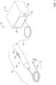
- FIG. 1 depicts an atherectomy system 10.
- the atherectomy system 10 may be electrically driven, pneumatically driven and/or driven in one or more other suitable manners. Additional or alternative components to those illustrated and described herein may be utilized in the operation of the atherectomy system 10.
- the atherectomy system 10 may include a drive assembly 12 and a control unit 14 (e.g., a controller).
- the drive assembly 12 may include, among other elements, an advancer assembly 16 and a rotation assembly 17.
- the control unit 14 is depicted as being separate from the drive assembly 12 in FIG. 1 , the functionality of the control unit 14 and the drive assembly 12 may be incorporated into a single component (e.g., in the advancer assembly 16 or other suitable single component).
- the rotation assembly 17 may include a drive shaft 18 (e.g., an elongate member that may be or may include a flexible drive shaft or other suitable drive shaft), a rotational device 20 (e.g., a rotational tip or other rotational device), and an elongate member 22 having a first end (e.g., a proximal end), a second end (e.g., a distal end), and a lumen extending from the first end to the second end for receiving the drive shaft 18.
- the elongate member 22 may be an elongated tubular member.
- the rotational device 20 may have a rough or sharp surface, such that it is configured to grind, abrade, cut, shave, etc. plaque from a vessel wall or other obstruction in a vessel when it is rotated.
- the advancer assembly 16 includes a knob 23, a housing 26, a drive mechanism (e.g., the drive mechanism 34 shown, for example, in FIG. 2 ), and/or one or more other suitable components.
- the housing 26 at least partially houses the drive mechanism and the knob 23 is at least partially accessible from an exterior of the housing 26.
- the drive mechanism may be or may include a motor (e.g., an electric motor, pneumatic motor, or other suitable motor) at least partially housed within the housing 26 and in communication with the knob 23, the drive shaft 18, and the control unit 14.
- the knob 23 may be configured to advance along a longitudinal path to longitudinally advance the drive mechanism 34 and the rotation assembly 17.
- the drive mechanism may be coupled to the drive shaft 18 in a suitable manner including, but not limited to, a weld connection, a clamping connection, an adhesive connection, a threaded connection, and/or other suitable connection configured to withstand rotational speeds and forces.
- a suitable manner including, but not limited to, a weld connection, a clamping connection, an adhesive connection, a threaded connection, and/or other suitable connection configured to withstand rotational speeds and forces.
- the drive shaft 18 may rotate over a wide range of speeds (e.g., at speeds of between zero (0) RPM and 250,000 RPM or higher)
- the coupling between the drive mechanism and the drive shaft 18 may be configured to withstand such rotational speeds and associated forces.
- the drive shaft 18 may be formed from one or more of a variety of materials.
- the drive shaft 18 may be formed from one or more of a variety of materials, including steel, stainless steel, other metal, polymer, and/or other suitable materials.
- the drive shaft 18 may have a suitable diameter and/or length for traversing vasculature of a patient.
- the diameter and/or the length of the drive shaft 18 may depend on the dimension of the lumen of the elongate member 22, the dimensions of vessels of a patient to be traversed, and/or one or more other suitable factors.
- the drive shaft 18 may have a diameter in a range from about 0.030 centimeters (cm) or smaller to about 0.150 cm or larger and a working length in a range from about ten (10) cm or shorter to about three hundred (300) cm or longer.
- the drive shaft 18 may have a diameter of about 0.05715 cm and a length of about fifty (50) cm.
- the drive shaft 18 may have a different suitable diameter and/or different suitable length.
- the rotational device 20 may have an outer perimeter which is equal to or larger than a distal diameter of the drive shaft 18 and/or the elongate member 22. Alternatively or in addition, the rotational device 20 may have an outer perimeter which is smaller than a diameter of the drive shaft 18 and/or the elongate member 22.
- the rotational device 20 may have a symmetric design so that it penetrates equally well in both rotational directions, but this is not required and the rotational device 20 may be configured to penetrate in only one direction.
- the rotational device 20 may be coupled to the drive shaft 18. Where the drive shaft 18 has a first end portion (e.g., a proximal end portion) and a second end portion (e.g., a distal end portion), the rotational device 20 may be coupled to the drive shaft 18 at or near the second end portion. In some cases, the rotational device 20 may be located at or adjacent a terminal end of the second end portion of the drive shaft 18.
- the rotational device 20 may be coupled to the drive shaft 18 in any manner.
- the rotational device 20 may be coupled to the drive shaft 18 with an adhesive connection, a threaded connection, a weld connection, a clamping connection, and/or other suitable connection configured to withstand rotational speeds and forces. Similar to as discussed above with respect to the connection between the drive shaft 18 and the drive mechanism, as the drive shaft 18 and/or the rotational device 20 may rotate at speeds between zero (0) RPM and 250,000 RPM or higher, the coupling between the drive shaft 18 and the rotational device 20 may be configured to withstand such rotational speeds and associated forces.
- the drive assembly 12 and the control unit 14 may be in communication and may be located in or may have a same housing and/or located in or have separate housings (e.g., the advancer assembly housing 26 and a control unit housing 28 or other housings). Whether in the same housing or in separate housings, the drive assembly 12 and the control unit 14 may be in communication through a wired connection (e.g., via one or more wires in an electrical connector 24 or other suitable electrical connector) and/or a wireless connection.
- a wired connection e.g., via one or more wires in an electrical connector 24 or other suitable electrical connector
- Wireless connections may be made via one or more communication protocols including, but not limited to, cellular communication, ZigBee, Bluetooth, Wi-Fi, Infrared Data Association (IrDA), dedicated short range communication (DSRC), EnOcean, and/or any other suitable common or proprietary wireless protocol, as desired.
- communication protocols including, but not limited to, cellular communication, ZigBee, Bluetooth, Wi-Fi, Infrared Data Association (IrDA), dedicated short range communication (DSRC), EnOcean, and/or any other suitable common or proprietary wireless protocol, as desired.
- the drive assembly 12 may include and/or enclose one or more operational features.
- the drive assembly 12 may include a motor (e.g., as discussed above and/or other suitable motor), rubber feet, control electronics, drive circuitry, etc.
- the control unit 14 which may be separate from the drive assembly 12 (e.g., as shown in FIG. 1 ) or may be included in the drive assembly 12, may include several features.
- the control unit 14 may include a display 30 and a control knob 32 (e.g., a motor speed (e.g., RPM or other speed) adjustment knob or other control knob).
- a control knob 32 e.g., a motor speed (e.g., RPM or other speed) adjustment knob or other control knob.
- control unit 14 may include one or more other features for controlling the drive mechanism and/or other features of the drive assembly 12 (e.g., one or more drive mechanism states of the drive mechanism) including, but not limited to, a processor, memory, input/output devices, a speaker, volume control buttons, on/off power supply switch, motor activation switch, a timer, a clock, and/or one or more other features.
- control unit 14 may include one or more drive mechanism load output control mechanisms for controlling an operation of the atherectomy system 10.
- control unit 14 may include a mechanism configured to set and/or adjust an advancing load output (e.g., a rotational speed) and/or a retracting load output from the drive mechanism 34.
- control unit 14 may include other control and/or safety mechanism for controlling the operation of the atherectomy system 10 and mitigating risks to patients.
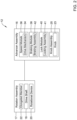
- FIG. 2 depicts a box diagram of the drive assembly 12 including the rotation assembly 17 and the advancer assembly 16.
- the rotation assembly 17 may include, among other components, the drive shaft 18, the rotational device 20, and the elongate member 22.
- the advancer assembly 16 may include (e.g., at least partially within the housing 26 depicted in FIG. 1 ), among other components, a knob assembly 25, a speed module 36, a braking module 38, and a lock module 40.
- the components of the advancer assembly 16 may be configured to communicate directly with one or more other components of the advancer assembly 16. Additionally or alternatively, the components of the advancer assembly 16 may communication with one or more other components of the advancer assembly 16 through electrical connections with a central controller having one or more processors, memory, and/or one or more other components of the advancer assembly 16.
- the knob assembly 25 may be or may include the knob 23 (e.g., an actuator or actuation mechanism of the knob assembly 25) that is at least partially accessible for adjustment and/or actuation from exterior of the housing 26 of the advancer assembly 16. Additionally or alternatively, the knob assembly 25 may include electrical connections, one or more processors, and/or memory to facilitate receiving input at the knob 23 and transferring signals to other components of the advancer assembly 16.
- the knob assembly 25 is in direct or indirect (e.g., indirectly via the central controller and/or other components, if desired) communication with one or more of the speed module 36, the braking module 38, the lock module 40 and/or other components of drive assembly 12 through an electrical connection, a mechanical connection, and/or other suitable connections.
- a single adjustment or actuation of the knob assembly 25 is configured to change two or more settings of the modules of the advancer assembly 16
- the knob 23 may be adjusted and/or actuated in one or more directions.
- the knob 23 may be longitudinally adjustable to longitudinally adjust and/or position the knob assembly 25, the knob 23 may be configured to rotate in a clockwise direction and/or a counter-clockwise direction, the knob 23 may be configured to be actuated in an axial direction along an axis about which the knob 23 may rotate, and/or the knob 23 may be adjusted and/or actuated in one or more other suitable manners.
- adjustment and/or actuation of the knob 23 may adjust one or more settings of one or more other components of the advancer assembly 16, as discussed in further detail below.
- the knob assembly 25 may take on one or more other forms.
- the knob assembly 25 may include an actuator or actuation mechanism being and/or having one or more of a physical button, a virtual button, a virtual knob, a physical knob, a touch sensitive surface, a shape other than what is depicted in the FIGs., one or more colors and/or color combinations, and/or other suitable feature configured for actuation or adjustment.
- the speed module 36 may include or may be in communication with the drive mechanism 34 via an electrical connection, a mechanical connection, and/or other suitable connections, to adjust a desired speed setting of the drive mechanism 34.
- the knob assembly 25 may include electrical connections, one or more processors, and/or memory to facilitate receiving input signals initiated from the knob assembly 25 and using the received signals to directly or indirectly (e.g., indirectly via the central controller, if desired) control settings and/or operation of the drive mechanism 34.
- the speed module 36 may be configured to adjust a speed setting of the drive mechanism 34 between a zero (0) speed setting and one or more additional speed settings and/or actuate a mode of the drive mechanism 34 in response to input or communications received from the knob assembly 25 or the central controller.
- the speed module 36 in response to a received input that is initiated by adjustment of the knob 23, is configured to adjust a speed setting between one of a zero (0) speed setting, a first speed setting (e.g., an advance speed setting), and a second speed setting (e.g., a withdraw or retract speed setting) and another one of the zero (0) speed setting, the first speed setting, and the second speed setting.
- the first speed setting is associated with a rotational speed for the rotational device 20 that facilitates advancement of the rotational device 20 through an obstruction or occlusion in a vessel of the patient and the second speed setting is associated with a rotational speed for the rotational device 20 that facilitates withdrawal (e.g., retraction) of the rotational device 20 within the vessel while mitigating risks of injury to the patient.
- the second speed setting may be lower than the first speed setting in the above example, but this is not required.
- the speed module 36 in response to a received input that is initiated by actuation or adjustment of the knob 23, the speed module 36 may actuate the drive mechanism 34 between an off mode and an on mode to initiate rotation of the drive mechanism 34 at a desired or set speed setting and accordingly rotate the rotational device 20.
- the braking module 38 may include a braking assembly 42 configured to engage a guidewire extending through the advancer assembly 16 and prevent rotation of the guidewire when the drive shaft 18 and/or the rotational device 20 rotate. Additionally or alternatively, the braking module 38 may include electrical connections, a processor, and/or memory configured to directly or indirectly (e.g., indirectly via the central controller, if desired) receive communications and/or other suitable inputs initiated by adjustment of the knob assembly 25 and adjust a brake setting (e.g., between an activated setting and a deactivated setting and/or between other suitable settings) of the braking assembly 42 in response to the communications and/or other inputs received.
- a brake setting e.g., between an activated setting and a deactivated setting and/or between other suitable settings
- adjustment of the knob assembly 25 may result in initiating a signal to the braking module 38 for the braking assembly 42 to enter an activated setting and engage a guidewire extending through the advancer assembly 16. Then, further adjustment of the knob assembly 25 may result in initiating a signal to the braking module 38 for the braking assembly 42 to enter a deactivated setting and disengage the guidewire to allow the rotation assembly 17 to be withdrawn over the guidewire.
- the braking assembly 42 may engage the guidewire extending through the advancer assembly 16 via a friction fit, a pinch fit, a pressure fit, and/or one or more other suitable types of engagement when in an activated setting.
- braking assembly 42 may be an electromechanical brake system configured to receive an electrical signal and in response to the electrical signal, either grasp the guidewire extending through the advancer assembly 16 or let go of the guidewire extending through the advancer assembly 16.
- the braking assembly 42 may be mechanical in nature and may be initiated through mechanical initiation.
- the braking assembly 42 may adjust and grasp or otherwise engage the guidewire extending through the housing 26 of the advancer assembly 16 as the knob 23 rotates.
- Other mechanical and/or electromechanical braking configurations are contemplated.
- the lock module 40 may include a locking assembly 41 to lock the knob assembly 25 at a longitudinal location along the housing 26 of the advancer assembly 16 in response to communications and/or other suitable inputs initiated by the knob assembly 25.
- the locking assembly 41 may include electrical connections, a processor, and/or memory configured to directly or indirectly (e.g., indirectly via the central controller or other suitable components, if desired) receive the communications and/or other suitable inputs initiated by adjustment of the knob assembly 25 and adjust a lock setting (e.g., between and activated setting and a deactivated setting and/or between other suitable settings) of the locking assembly 41 in response to the communications and/or other inputs received.
- adjustment of the knob assembly 25 may result in initiating a signal to the lock module 40 for the locking assembly 41 to enter an activated setting and prevent the knob assembly 25 from adjusting longitudinally with respect to the housing 26 of the advancer assembly 16. Then, further adjustment of the knob assembly 25 may result in initiating a signal to the lock module 40 for the locking assembly 41 to enter a deactivated setting and allow the knob assembly 25 to adjust longitudinally with respect to the housing 26 of the advancer assembly 16.
- the locking assembly 41 may be configured to lock the knob assembly 25 at a longitudinal location along the housing 26 of the advancer assembly 16 in one or more suitable manners.
- the locking assembly 41 may be configured to engage the housing 26 or a feature extending from the housing 26 via a friction fit, a pinch fit, a pressure fit, and/or one or more other suitable types of engagement when in an activated setting.
- the locking assembly may be an electromechanical lock system configured to receive an electrical signal and in response to receiving the electrical signal, either engage the housing 26 and/or other component of the advancer assembly 16 or disengage the housing 26 and/or other component of the advancer assembly 16.
- the locking assembly 41 may be mechanical in nature and may be initiated through mechanical initiation.
- the locking assembly 41 may rotate and engage the housing 26 of the advancer assembly 16 as the knob 23 is rotating. In another example, the locking assembly 41 may be biased in a lock position and move to an unlocked position in response to actuation.
- Other mechanical and/or electromechanical locking configurations are contemplated.
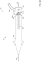
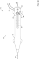
- FIGs. 3A-3D depict the example advancer assembly 16 showing the knob assembly 25 in various modes based on position configurations of the knob 23, where each mode of the knob assembly 25 is configured to set settings of various modules to predetermined settings.
- the described modes of the knob assembly 25 and associated settings for modules of the advancer assembly 16 are illustrative and it is contemplated other modes of the knob assembly 25 and/or settings of the modules may be utilized, as desired.
- the knob 23 is depicted and described as being associated with modes of the knob assembly 25 at quarter (1/4) turn positions in FIGs.
- knob 23 may be positioned and/or associated with one or modes of the knob assembly 25 at any suitable rotatable position relative to a full turn of the knob 23 (e.g., half (1/2) turns, eighth (1/8) turns, three quarter (3/4) turns, other suitable partial or full turns, and the like).
- FIG. 3A depicts the advancer assembly 16 with the knob 23 in a distal or forward configuration and setting the knob assembly 25 to an advance mode.
- FIG. 3B depicts the advancer assembly 16 with the knob 23 in an upward configuration and setting the knob assembly 25 to a lock mode.
- FIG. 3C depicts the advancer assembly 16 with the knob 23 in a proximal or backward configuration and setting the knob assembly 25 to a withdraw mode.
- FIG. 3D depicts the advancer assembly 16 with the knob 23 in a downward configuration and setting the knob assembly 25 to the lock mode.
- FIGs. 3A-3D depict the knob 23 sequentially adjusted in a clockwise direction, it is contemplated that the knob 23 may be rotated in a counter-clockwise direction.
- the knob 23 or the knob assembly 25 may include a knob indicator that indicates or points to a configuration of the knob 23 and a mode of the knob assembly 25.
- the knob 23 may include a knob indicator 66.
- the knob indicator 66 may be a dot on, an arrow-shaped portion of, the inherent shape of the knob 23, color of the knob 23, or other suitable configuration on or of the knob 23, as desired.
- the advancer assembly 16 may include, as discussed above, the knob assembly 25, the speed module 36, the braking module 38, and the lock module 40, and one or more settings of the speed module 36, the braking module 38, and/or the lock module 40 may be adjusted in response to adjustment and/or actuation of the of the knob 23 between the example configurations depicted in FIGs. 3A-3D and/or other suitable configurations.
- Such a configured advancer assembly 16 of an atherectomy system 10 may facilitate limiting a number of steps required to prepare settings for different modules or components of the atherectomy system 10 prior to and/or during use of the atherectomy system 10 in a procedure. For example, adjusting the knob 23 to point distally or forward, as depicted in FIG.
- an actuator or actuation mechanism may adjust settings of the speed module 36, the braking module 38, and/or the lock module 40 for advancement of a rotational device (e.g., the rotational device 20 or other suitable rotational device) within a vessel of a patient, whereas in previous atherectomy systems it was necessary to separately adjust a speed setting (e.g., with a foot pedal), adjust a brake setting (e.g., on an advancer assembly), and adjust a lock mechanism (e.g., at a knob) to prepare the atherectomy system for advancement of the rotational device within a vessel of a patient.
- the single adjustment of an actuator or actuator mechanism to adjust settings of multiple components of the atherectomy system 10 mitigates human error by requiring fewer steps when changing how the atherectomy system is being used (e.g., between advancement and retraction, etc.).
- the housing 26 of the advancer assembly 16 may include indicia on an outer surface 60.
- the indicia on the housing 26 may include, but is not limited to, descriptive indicia indicating a mode in which the knob assembly 25 is positioned. This indicia may be graphical representations of the modes in which the knob assembly 25 is positioned (e.g., a lock icon representing a lock mode, a retract icon representing a retract mode, etc.).
- indicia may be provided at predetermined and/or consistent locations along an opening 58 to provide a user (e.g., a physician or other user) with a measurement or other indication of an axial position of the drive mechanism 34, the drive shaft 18, and/or the rotational device 20.
- Such indicia may be tick marks, measurements (e.g., millimeters, centimeters, inches, etc.), and/or other suitable indicia that facilitate providing an understanding of a relative position of the knob assembly 25 and/or the drive mechanism 34 along the opening 58.
- the shape and/or color of the knob 23 may indicate a mode in which the knob assembly 25 is positioned (e.g., the knob 23 may include one or more colors, where the color of the knob 23 at a predetermined position (e.g., a forward position, a backward position, a side position, a position aligned with indicia on the housing 26, and/or other suitable predetermined position) indicates a current mode of the knob assembly 25).
- a predetermined position e.g., a forward position, a backward position, a side position, a position aligned with indicia on the housing 26, and/or other suitable predetermined position
- a brake indicator 56 may be included on and/or adjacent the outer surface 60 of the housing 26 to indicate (e.g., by luminescence, LED, digital display, and/or other suitable types of indicia) to a user that the braking assembly 42 is in one of an activated mode and a deactivated mode.
- FIG. 3A depicts an example of the advancer assembly 16 showing the knob assembly 25 in the advance mode.
- the knob indicator 66 of or in communication with the knob 23 may be directed toward a distal end of the advancer assembly 16.
- various modes of the knob assembly 25 and/or setting of modules of the advancer assembly 16 may be described as being associated with a position of the knob 23 or direction of the knob indicator 66, the modes and/or settings of modules may be associated with any suitable position of the knob 23 or direction of the knob indicator 66.
- a signal may be initiated such that the braking module 38 may receive a signal to adjust a brake setting to an activated setting.
- the braking assembly 42 may engage a guidewire 44, as discussed above with respect to FIG. 2 , and may restrict movement (e.g., rotational and/or longitudinal movement) of the guidewire 44 relative to the rotation assembly 17 and/or the advancer assembly 16.
- the brake indicator 56 may be illuminated, as shown for example in FIG. 3A , or turned off to indicate the braking module 38 is in the activated setting.
- the signal initiated when the knob assembly 25 is set to the advance mode may result in the lock module 40 receiving a signal to adjust a lock setting to a deactivated setting.
- the locking assembly 41 may unlock the knob assembly 25 relative to the housing 26 of the advancer assembly 16. Unlocking the knob assembly 25 relative to the housing 26 may allow for movement of the knob 23 along the longitudinal slot or opening 58 to advance and/or withdraw the rotational device 20 (not shown in FIGs. 3A-3D ) in communication with knob assembly 25 with respect to the advancer assembly 16.
- tick marks or other indicia along the longitudinal slot or opening 58 may indicate to a user how far the rotational device has been advanced as the knob 23 adjusts longitudinally.
- the signal initiated when the knob assembly 25 is set to the advance mode may result in the speed module 36 receiving a signal to adjust a speed setting to a first speed setting (e.g., an advance speed setting).
- a first speed setting e.g., an advance speed setting
- the drive mechanism 34 may be set to operate at an advance speed.
- the advance speed may be a predetermined speed and/or adjustable speed at which the drive mechanism is to operate to rotate the rotational device 20 to facilitate passing an obstruction in a patient's vessel.
- the speed module 36 may automatically initiate movement of the drive mechanism 34 at the advance speed to rotate the rotational device 20.
- an actuation of the knob 23 or other actuator in addition to adjustment of the knob 23 to a distal or forward configuration may be required to initiate movement of the drive mechanism 34, as discussed for example with respect to FIGs. 4A-4E . Requiring such actuation of the knob 23 or other actuator in addition to adjustment of the knob 23 to a distal or forward configuration to initiate movement of the drive mechanism 34 may allow for a user of the atherectomy system 10 to have the knob assembly 25 in the advance mode without rotation of the rotational device 20.
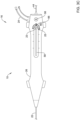
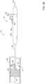
- FIG. 3B depicts an example of the advancer assembly 16 showing the knob assembly 25 in the lock mode.
- the knob indicator 66 of or in communication with the knob 23 may have been adjusted in a clockwise direction such that the knob indicator 66 is directed upward and/or substantially perpendicular to a longitudinal axis of the advancer assembly 16.
- a signal may be initiated such that the braking module 38 may receive a signal to adjust a brake setting to a deactivated setting.
- the braking assembly 42 may disengage the guidewire 44 to allow and/or facilitate movement (e.g., rotational and/or longitudinal movement) of the guidewire 44 relative to the rotation assembly 17 and/or the advancer assembly 16.
- the brake indicator 56 may be turned off or otherwise not illuminated, as shown for example in FIG. 3B , or turned on to indicate the braking module 38 is in the deactivated setting.
- the signal initiated when the knob assembly 25 is set to the lock mode may result in the lock module 40 receiving a signal to adjust a lock setting to an activated setting.
- the locking assembly 41 may lock the knob assembly 25 relative to the housing 26 of the advancer assembly 16. Locking the knob assembly 25 relative to the housing 26 may restrict or prevent movement of the knob 23 along the longitudinal slot or opening 58 to restrict or prevent longitudinal movement (e.g., advancing or withdrawing) of a rotational device in communication with knob assembly 25 with respect to the advancer assembly 16.
- the signal initiated when the knob assembly 25 is set to the lock mode may result in the speed module 36 receiving a signal to adjust a speed setting to a zero (0) speed setting (e.g., a stop speed setting).
- a zero (0) speed setting e.g., a stop speed setting
- the drive mechanism 34 may be set to prevent operation of the drive mechanism 34 and thus, rotation of the rotational device 20. Accordingly, when the speed module is in the zero (0) speed setting, the drive mechanism 34 may not operate or cause rotation of the rotational device 20 even in response to the knob 23 or other actuator being actuated to initiate operation of the drive mechanism 34 because the drive mechanism 34 is set to operate at a zero (o) speed.
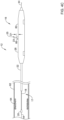
- FIG. 3C depicts an example of the advancer assembly 16 showing the knob assembly 25 in the withdraw mode.
- the knob indicator 66 of or in communication with the knob 23 may be adjusted in a clockwise direction such that the knob indicator 66 is directed toward a proximal end of the advancer assembly 16.
- a signal may be initiated such that the braking module 38 may receive a signal to adjust or maintain a brake setting to or in a deactivated setting.
- the braking assembly 42 may disengage or be disengaged from the guidewire 44 to allow or facilitate movement (e.g., rotational and/or longitudinal movement) of the guidewire 44 relative to the rotation assembly 17 and/or the advancer assembly 16.
- the brake indicator 56 may be turned off or otherwise not illuminated, as shown for example in FIG. 3C , or turned on to indicate the braking module 38 is in the deactivated setting.
- the signal initiated when the knob assembly 25 is set to the withdraw mode may result in the lock module 40 receiving a signal to adjust a lock setting to a deactivated setting.
- the locking assembly 41 may unlock the knob assembly 25 relative to the housing 26 of the advancer assembly 16. Unlocking the knob assembly 25 relative to the housing 26 may allow for movement of the knob 23 along the longitudinal slot or opening 58 to advance and/or withdraw the rotational device 20 in communication with knob assembly 25 with respect to the advancer assembly 16.
- tick marks or other indicia along the longitudinal slot or opening 58 may indicate to a user how far the rotational device has traveled as the knob 23 adjusts longitudinally.
- the signal initiated when the knob assembly 25 is set to the withdraw mode may result in the speed module 36 receiving a signal to adjust a speed setting to a second speed setting (e.g., a withdraw speed setting).
- a second speed setting e.g., a withdraw speed setting
- the drive mechanism 34 may be set to operate at a withdraw speed.
- the withdraw speed may be a predetermined speed and/or adjustable speed at which the drive mechanism is to operate to rotate the rotational device 20 to withdraw the rotational device 20 within the vessel of the patient.
- the second speed setting or withdraw speed setting may be a lower speed than the first speed setting or advance speed setting.
- the withdraw speed setting may be configured to facilitate removal of the rotational device 20 from the patient's vessel and can be lower than the advance speed setting, as the rotational device 20 is not typically trying to burr through an obstruction in the patient's vessel when the knob assembly 25 is in the withdraw mode.
- the withdraw speed setting may be configured to break up friction of the rotation assembly 17 with the guidewire 44 and/or other friction inhibiting withdrawal of the rotation assembly 17.
- the speed module 36 may automatically initiate movement of the drive mechanism 34 at the withdraw speed to rotate the rotational device 20.
- an actuation of the knob 23 or other actuator in addition to adjustment of the knob 23 to a proximal or backward configuration may be required to initiate movement of the drive mechanism 34, as discussed for example with respect to FIGs. 4A-4E . Requiring such actuation of the knob 23 or other actuator in addition to adjustment of the knob 23 to a proximal or backward configuration to initiate movement of the drive mechanism 34 may allow for a user of the atherectomy system 10 to have the knob assembly 25 in the withdraw mode without rotation of the rotational device 20.
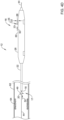
- FIG. 3D depicts an example of the advancer assembly 16 showing the knob assembly 25 in the lock mode.
- the knob indicator 66 of or in communication with the knob 23 may have been adjusted in a clockwise direction such that the knob indicator 66 is directed downward or substantially perpendicular to a longitudinal axis of the advancer assembly 16.
- Such adjustment of the knob 23 to place the knob assembly 25 in the lock mode may result in initiating a signal such that the braking module 38, the lock module 40, and/or the speed module 36 receive signals to set settings similar to as discussed above with respect to FIG. 3B .
- one or more of the braking module 38, the lock module 40, and/or the speed module 36 may receive signals to adjust one or more setting in a manner different than discussed above with respect to FIG. 3B .
- FIGs. 4A-4E depict side views of the drive assembly 12 of the atherectomy system 10 showing schematic views of an example method of using the atherectomy system 10 to advance through a vessel 62 of a patient and pass an occlusion 64 within the vessel 62, where the vessel 62 and the occlusion 64 are depicted in cross-section.
- FIG. 4A depicts the atherectomy system 10 inserted into a patient's vessel 62 over the guidewire 44, with the rotational device 20 not rotating and proximal of the occlusion 64.
- FIG. 4B depicts the atherectomy system 10 inserted into the patient's vessel 62 over the guidewire 44, with the rotational device 20 rotating and being advanced toward the occlusion 64.
- FIG. 4A depicts the atherectomy system 10 inserted into a patient's vessel 62 over the guidewire 44, with the rotational device 20 rotating and being advanced toward the occlusion 64.
- FIG. 4C depicts the atherectomy system 10 inserted into the patient's vessel 62 over the guidewire 44, with the rotational device 20 not rotating and advanced through the occlusion 64.
- FIG. 4D depicts the atherectomy system 10 inserted into the patient's vessel 62 over the guidewire 44, with the rotational device 20 rotating and being withdrawn from the occlusion 64.
- FIG. 4E depicts the atherectomy system 10 withdrawn from the patient's vessel 62 over the guidewire 44, with the rotational device 20 not rotating.
- the drive shaft 18, the rotational device 20, and the elongate member 22 of the drive assembly 12 have been inserted over the guidewire 44 into a vessel 62 of a patient to a location proximal of the occlusion 64.
- the drive assembly 12 may be inserted into the vessel 62 while the knob assembly 25 is in the lock mode, and when the rotational device 20 is located at a target location proximal of the occlusion 64, the knob 23 may be rotated such that the knob assembly 25 is in an advance mode, as shown in FIG. 4A .
- the braking module 38 may be set to an activated setting
- the lock module 40 may be set to a deactivated setting
- the speed module 36 may be set to an advance speed setting.
- the rotational device 20 is not rotating even though the knob assembly 25 is in the advance mode. As such, actuation of the knob 23 may be required to initiate rotation of the rotational device 20 based on the advance setting for the drive mechanism 34 (not shown in FIG. 4A ) within the housing 26 of the advancer assembly 16
- the knob 23 may be actuated by pressing on or applying a force to a top of the knob 23.
- the knob 23 may be biased (e.g., via a spring or other suitable biasing mechanism) to the unactuated state, but this is not required.
- FIG. 4B depicts the knob assembly 25 in the advance mode and the knob 23 in an actuated state, with a force (not shown) pressed on or otherwise applied to the top of the knob 23 to cause movement of the drive mechanism 34 and rotation of the rotational device 20 in the direction of rotational arrow 49.
- a force not shown
- the knob 23 When the knob 23 is actuated, there may be a distance D2 between the outer surface 60 of the housing 26 and the top of the knob 23. This distance D2 may be less than the distance D1, but this is not required in all instances.
- the knob 23 While the knob 23 is actuated and the rotational device 20 is rotating based on the advance mode of the drive mechanism 34, the knob 23 may be longitudinally advanced along the housing 26 in the direction of arrow 46. Advancing the knob 23 in the direction of the arrow 46 may cause the drive shaft 18 and the rotational device 20 to advance toward and/or into the occlusion 64 in the direction of arrow 48 while the rotational device 20 is rotating to burr through the occlusion 64.
- the force pressed on or otherwise applied to the top of the knob 23 may be removed and the knob 23 may return to unactuated state, where a distance between the outer surface 60 of the housing 26 and the top of the knob 23 is the distance D1.
- the knob 23 may be adjusted such that the knob assembly 25 is in the withdraw mode, as depicted in FIG. 4D .
- the braking module 38 may be set to the deactivated setting
- the lock module 40 may be set to the deactivated setting
- the speed module 36 may be set to a withdraw speed setting.
- the knob 23 in FIG. 4D is in an actuated state, with a force pressed on or otherwise applied to the top of the knob 23 to cause movement of the drive mechanism 34 and rotation of the rotational device 20 in the direction of the rotational arrow 49 and at a speed associated with the withdraw speed setting of the drive mechanism 34.
- actuation of the knob 23 while the knob assembly 25 is in the withdraw mode may cause rotation of the rotational device 20 in a direction opposite of the direction of the rotational arrow 49.
- the knob 23 may be longitudinally withdrawn along the housing in the direction of arrow 50. Axially translating the knob 23 in the direction of the arrow 50 may cause the drive shaft 18 and the rotational device 20 to withdraw within the vessel 62 in the direction of arrow 52 while the rotational device 20 is rotating.
- the steps of advancing the rotational device 20 across the occlusion 64 and withdrawing the rotational device 20 may be repeated until the occlusion 64 has been sufficiently addressed (e.g., partially or fully removed or broken apart).
- the knob 23 may be fully withdrawn along the housing 26 and adjusted such that the knob assembly 25 is in the lock mode, as depicted in FIG. 4E .
- the braking module 38 may be set to the deactivated setting
- the lock module 40 may be set to the activated setting
- the speed module 36 may be set to a zero (0) speed setting.
- the advancer assembly 16 may be moved in the direction of arrow 54 relative to the vessel 62 to withdraw the drive shaft 18, the rotational device 20, and/or the elongate member 22 from the vessel 62.
- the methods and system described herein may include one or more steps other than those steps described herein and/or the described steps may be performed in one or more other orders, as desired unless expressly indicated otherwise. Moreover, the methods described herein may be repeated during operation of the atherectomy system 10 upon request or initiation, continuously, continuously at predetermined intervals, and/or at other times. Additionally, one or more additional medical devices including, but not limited to, a guide catheter, sheath, introducer, a filter, and/or other suitable medical devices not necessarily described or discussed herein may be utilized with the atherectomy system 10 to facilitate use of the atherectomy system 10 in vasculature of a patient.
- additional medical devices including, but not limited to, a guide catheter, sheath, introducer, a filter, and/or other suitable medical devices not necessarily described or discussed herein may be utilized with the atherectomy system 10 to facilitate use of the atherectomy system 10 in vasculature of a patient.
Landscapes
- Health & Medical Sciences (AREA)
- Surgery (AREA)
- Life Sciences & Earth Sciences (AREA)
- Biomedical Technology (AREA)
- Nuclear Medicine, Radiotherapy & Molecular Imaging (AREA)
- Engineering & Computer Science (AREA)
- Vascular Medicine (AREA)
- Heart & Thoracic Surgery (AREA)
- Medical Informatics (AREA)
- Molecular Biology (AREA)
- Animal Behavior & Ethology (AREA)
- General Health & Medical Sciences (AREA)
- Public Health (AREA)
- Veterinary Medicine (AREA)
- Surgical Instruments (AREA)
Claims (9)
- Vorschubanordnung (16) für eine Atherektomie-Vorrichtung, aufweisend:ein Gehäuse (26);einen in dem Gehäuse (26) angeordneten Antriebsmechanismus (34);einen Betätigungsmechanismus (23), der in Kommunikation mit dem Antriebsmechanismus (34) ist und von außerhalb des Gehäuses (26) zugänglich ist;ein erstes Funktionsmodul;ein zweites Funktionsmodul; undwobei eine einzige Anpassung des Betätigungsmechanismus (23) eine Einstellung des ersten Funktionsmoduls der Vorschubanordnung (16) und eine Einstellung des zweiten Funktionsmoduls der Vorschubanordnung (16) anpasst,wobei das erste Funktionsmodul der Vorschubanordnung (16) ein Geschwindigkeitsmodul (36) ist, das konfiguriert ist, um als Antwort auf die Anpassung des Betätigungsmechanismus (23) eine Geschwindigkeitseinstellung des Antriebsmechanismus (34) zwischen einer ersten Nichtnull-Geschwindigkeitseinstellung, einer zweiten Nichtnull-Geschwindigkeitseinstellung und einer Null-Geschwindigkeitseinstellung anzupassen, wobei die erste Nichtnull-Geschwindigkeitseinstellung mit einer Drehgeschwindigkeit für eine Drehvorrichtung (20) assoziiert ist, die ein Vorschieben der Drehvorrichtung (20) durch eine Obstruktion oder Okklusion in einem Gefäß eines Patienten erleichtert, und die zweite Nichtnull-Geschwindigkeitseinstellung mit einer Drehgeschwindigkeit für die Drehvorrichtung (20) assoziiert ist, die ein Zurückziehen der Drehvorrichtung (20) in dem Gefäß erleichtert, dabei Risiken einer Verletzung des Patienten mindert, undwobei das zweite Funktionsmodul der Vorschubanordnung (16) ein Bremsmodul (38) ist, das konfiguriert ist, um eine Bremsanordnung (42) zu aktivieren oder zu deaktivieren, die konfiguriert ist, um als Antwort auf die Anpassung des Betätigungsmechanismus (23) einen sich durch das Gehäuse (26) erstreckenden Führungsdraht (44) zu greifen.
- Vorschubanordnung (16) nach Anspruch 1, wobei eine Betätigung des Betätigungsmechanismus (23) außerdem eine Betätigung des Antriebsmechanismus (34) gemäß der angepassten Geschwindigkeitseinstellung initiiert.
- Vorschubanordnung (16) nach Anspruch 2, ferner aufweisend ein drittes Funktionsmodul, wobei das dritte Funktionsmodul der Vorschubanordnung (16) ein Verriegelungsmodul (40) ist, das konfiguriert ist, um eine Verriegelungsanordnung (41) zu aktivieren oder zu deaktivieren, wobei die Betätigung des Betätigungsmechanismus (23) die Verriegelungsanordnung (41) deaktiviert.
- Vorschubanordnung (16) nach Anspruch 3, wobei die Anpassung des Betätigungsmechanismus (23) eine Einstellung des dritten Funktionsmoduls der Vorschubanordnung (16) anpasst.
- Vorschubanordnung (16) nach Anspruch 3 oder 4, wobei das dritte Funktionsmodul konfiguriert ist, um als Antwort auf die Anpassung des Betätigungsmechanismus (23) eine Verriegelungsanordnung (41) zu aktivieren oder zu deaktivieren.
- Vorschubanordnung (16) nach einem der Ansprüche 1 bis 5, wobei der Betätigungsmechanismus (23) einen Knopf aufweist, wobei der Knopf axial entlang des Gehäuses (26) gleitbar ist.
- Vorschubanordnung (16) nach einem der Ansprüche 1 bis 6, wobei die Anpassung des Betätigungsmechanismus (23) eine erste Anpassung des Betätigungsmechanismus (23) ist, und eine zweite Anpassung des Betätigungsmechanismus (23) ferner die Einstellung des ersten Funktionsmoduls der Vorschubanordnung (16) und die Einstellung des zweiten Funktionsmoduls der Vorschubanordnung (16) anpasst.
- Vorschubanordnung (16) nach einem der Ansprüche 1 bis 7, wobei die Vorschubanordnung (16) in Kommunikation mit einer Drehanordnung (17) ist, die Drehanordnung (17) ein längliches Element (22) aufweist, das an einem distalen Ende des länglichen Elements (22) mit einer Drehvorrichtung (20) gekoppelt ist, und der Antriebsmechanismus (34) konfiguriert ist, um das längliche Element (22) auf Basis der Geschwindigkeitseinstellung zu drehen.
- Vorschubanordnung (16) nach einem der Ansprüche 1 bis 7, wobei der Betätigungsmechanismus (23) in elektrischer Verbindung mit dem Antriebsmechanismus (34) ist.
Priority Applications (1)
| Application Number | Priority Date | Filing Date | Title |
|---|---|---|---|
| EP25151423.8A EP4527318A3 (de) | 2018-04-10 | 2019-04-10 | Rotierende medizinische vorrichtung |
Applications Claiming Priority (2)
| Application Number | Priority Date | Filing Date | Title |
|---|---|---|---|
| US201862655593P | 2018-04-10 | 2018-04-10 | |
| PCT/US2019/026801 WO2019199981A1 (en) | 2018-04-10 | 2019-04-10 | Rotational medical device |
Related Child Applications (1)
| Application Number | Title | Priority Date | Filing Date |
|---|---|---|---|
| EP25151423.8A Division EP4527318A3 (de) | 2018-04-10 | 2019-04-10 | Rotierende medizinische vorrichtung |
Publications (2)
| Publication Number | Publication Date |
|---|---|
| EP3773269A1 EP3773269A1 (de) | 2021-02-17 |
| EP3773269B1 true EP3773269B1 (de) | 2025-01-15 |
Family
ID=66248857
Family Applications (2)
| Application Number | Title | Priority Date | Filing Date |
|---|---|---|---|
| EP19719126.5A Active EP3773269B1 (de) | 2018-04-10 | 2019-04-10 | Medizinische drehvorrichtung |
| EP25151423.8A Pending EP4527318A3 (de) | 2018-04-10 | 2019-04-10 | Rotierende medizinische vorrichtung |
Family Applications After (1)
| Application Number | Title | Priority Date | Filing Date |
|---|---|---|---|
| EP25151423.8A Pending EP4527318A3 (de) | 2018-04-10 | 2019-04-10 | Rotierende medizinische vorrichtung |
Country Status (4)
| Country | Link |
|---|---|
| US (2) | US11331119B2 (de) |
| EP (2) | EP3773269B1 (de) |
| JP (1) | JP7366926B2 (de) |
| WO (1) | WO2019199981A1 (de) |
Families Citing this family (10)
| Publication number | Priority date | Publication date | Assignee | Title |
|---|---|---|---|---|
| WO2018204700A1 (en) | 2017-05-03 | 2018-11-08 | Medtronic Vascular, Inc. | Tissue-removing catheter with guidewire isolation liner |
| US11690645B2 (en) | 2017-05-03 | 2023-07-04 | Medtronic Vascular, Inc. | Tissue-removing catheter |
| EP3817673B1 (de) | 2018-08-07 | 2024-11-20 | Cardio Flow, Inc. | Atherektomievorrichtungen |
| EP4434477A3 (de) | 2018-11-16 | 2024-11-27 | Medtronic Vascular Inc. | Gewebeentfernungskatheter |
| US11819236B2 (en) | 2019-05-17 | 2023-11-21 | Medtronic Vascular, Inc. | Tissue-removing catheter |
| USD988511S1 (en) | 2019-11-15 | 2023-06-06 | Medtronic Vascular, Inc | Catheter handle |
| US11696793B2 (en) * | 2021-03-19 | 2023-07-11 | Crossfire Medical Inc | Vascular ablation |
| EP4391932A1 (de) * | 2021-08-27 | 2024-07-03 | Boston Scientific Scimed, Inc. | Atherektomiesystem mit anterograder und retrograder ablation |
| WO2023219965A1 (en) * | 2022-05-08 | 2023-11-16 | The Board Of Trustees Of The Leland Stanford Junior University | Devices, systems, and methods for performing thrombectomy procedures |
| WO2024005881A1 (en) * | 2022-06-30 | 2024-01-04 | Cardiovascular Systems, Inc. | Systems, devices and methods for monitoring current in a rotational medical device and led monitoring and display arrays for annunciating current and peak values of a monitored variable |
Family Cites Families (11)
| Publication number | Priority date | Publication date | Assignee | Title |
|---|---|---|---|---|
| BR8706114A (pt) | 1986-11-14 | 1988-06-21 | Squibb & Sons Inc | Aparelhagem ablativa giratoria acionada a gas para aplicacoes medicas |
| US5893857A (en) * | 1997-01-21 | 1999-04-13 | Shturman Cardiology Systems, Inc. | Handle for atherectomy device |
| US6024749A (en) * | 1997-10-27 | 2000-02-15 | Shturman Cardiology Systems, Inc. | Rotational atherectomy device with improved exchangeable drive shaft cartridge |
| JP3798983B2 (ja) * | 2000-04-05 | 2006-07-19 | パスウェイ メディカル テクノロジーズ インコーポレイテッド | 経管的に閉塞物質を除去するシステム |
| US7344546B2 (en) | 2000-04-05 | 2008-03-18 | Pathway Medical Technologies | Intralumenal material removal using a cutting device for differential cutting |
| US20100125253A1 (en) * | 2008-11-17 | 2010-05-20 | Avinger | Dual-tip Catheter System for Boring through Blocked Vascular Passages |
| WO2010129075A1 (en) * | 2009-04-28 | 2010-11-11 | Avinger, Inc. | Guidewire support catheter |
| US9050126B2 (en) * | 2010-02-26 | 2015-06-09 | Cardiovascular Systems, Inc. | Rotational atherectomy device with electric motor |
| US9332998B2 (en) * | 2012-08-13 | 2016-05-10 | Covidien Lp | Apparatus and methods for clot disruption and evacuation |
| US9844390B2 (en) * | 2013-07-25 | 2017-12-19 | Cardiovascular Systems, Inc. | Rotational atherectomy device with exchangeable drive shaft and meshing gears |
| US10226276B2 (en) * | 2015-06-26 | 2019-03-12 | Covidien Lp | Tissue-removing catheter including operational control mechanism |
-
2019
- 2019-04-10 EP EP19719126.5A patent/EP3773269B1/de active Active
- 2019-04-10 JP JP2020555414A patent/JP7366926B2/ja active Active
- 2019-04-10 EP EP25151423.8A patent/EP4527318A3/de active Pending
- 2019-04-10 US US16/380,587 patent/US11331119B2/en active Active
- 2019-04-10 WO PCT/US2019/026801 patent/WO2019199981A1/en not_active Ceased
-
2022
- 2022-04-19 US US17/724,172 patent/US11839399B2/en active Active
Also Published As
| Publication number | Publication date |
|---|---|
| JP7366926B2 (ja) | 2023-10-23 |
| US20190307483A1 (en) | 2019-10-10 |
| JP2021517840A (ja) | 2021-07-29 |
| US20220240975A1 (en) | 2022-08-04 |
| WO2019199981A1 (en) | 2019-10-17 |
| US11331119B2 (en) | 2022-05-17 |
| US11839399B2 (en) | 2023-12-12 |
| EP4527318A2 (de) | 2025-03-26 |
| EP4527318A3 (de) | 2025-06-25 |
| EP3773269A1 (de) | 2021-02-17 |
Similar Documents
| Publication | Publication Date | Title |
|---|---|---|
| EP3773269B1 (de) | Medizinische drehvorrichtung | |
| EP3737310B1 (de) | Medizinische drehvorrichtung | |
| RU2537765C2 (ru) | Устройство для удаления материала и способ применения | |
| US11730510B2 (en) | Atherectomy devices and methods | |
| US10405878B2 (en) | Rotatable medical device | |
| US20210322052A1 (en) | Atherectomy system | |
| EP3806760B1 (de) | Atherektomievorrichtungen | |
| CN112654311A (zh) | 具有导丝检测传感器的组织移除导管 | |
| WO2016011312A1 (en) | Methods, devices and systems for slow rotation of drive shaft driven atherectomy systems | |
| WO2018219842A1 (en) | Hand-held device for inserting a needle into a non-homogeneous material, particularly for intravenous catheterization | |
| JP2023531474A (ja) | 応答を加速させた吸引システム | |
| CN117797384A (zh) | 压力注射泵 | |
| EP4387544B1 (de) | Atherektomiesystem mit wiederverwendbarem teil und einwegteil | |
| US20250134549A1 (en) | Atherectomy system with direction-specific stall stop mechanism | |
| EP4312827B1 (de) | Debulking-katheter | |
| US20230218314A1 (en) | Atherectomy system adapted to enable retrograde ablation | |
| WO2025096378A1 (en) | Atherectomy burr adapted for retrograde ablation with limited driveshaft windup | |
| CN116634957A (zh) | 用于可操纵导管的单动手柄 |
Legal Events
| Date | Code | Title | Description |
|---|---|---|---|
| STAA | Information on the status of an ep patent application or granted ep patent |
Free format text: STATUS: UNKNOWN |
|
| STAA | Information on the status of an ep patent application or granted ep patent |
Free format text: STATUS: THE INTERNATIONAL PUBLICATION HAS BEEN MADE |
|
| PUAI | Public reference made under article 153(3) epc to a published international application that has entered the european phase |
Free format text: ORIGINAL CODE: 0009012 |
|
| STAA | Information on the status of an ep patent application or granted ep patent |
Free format text: STATUS: REQUEST FOR EXAMINATION WAS MADE |
|
| 17P | Request for examination filed |
Effective date: 20201025 |
|
| AK | Designated contracting states |
Kind code of ref document: A1 Designated state(s): AL AT BE BG CH CY CZ DE DK EE ES FI FR GB GR HR HU IE IS IT LI LT LU LV MC MK MT NL NO PL PT RO RS SE SI SK SM TR |
|
| AX | Request for extension of the european patent |
Extension state: BA ME |
|
| DAV | Request for validation of the european patent (deleted) | ||
| DAX | Request for extension of the european patent (deleted) | ||
| RAP1 | Party data changed (applicant data changed or rights of an application transferred) |
Owner name: BOSTON SCIENTIFIC MEDICAL DEVICE LIMITED |
|
| STAA | Information on the status of an ep patent application or granted ep patent |
Free format text: STATUS: EXAMINATION IS IN PROGRESS |
|
| 17Q | First examination report despatched |
Effective date: 20240517 |
|
| GRAP | Despatch of communication of intention to grant a patent |
Free format text: ORIGINAL CODE: EPIDOSNIGR1 |
|
| STAA | Information on the status of an ep patent application or granted ep patent |
Free format text: STATUS: GRANT OF PATENT IS INTENDED |
|
| INTG | Intention to grant announced |
Effective date: 20240830 |
|
| GRAS | Grant fee paid |
Free format text: ORIGINAL CODE: EPIDOSNIGR3 |
|
| GRAA | (expected) grant |
Free format text: ORIGINAL CODE: 0009210 |
|
| STAA | Information on the status of an ep patent application or granted ep patent |
Free format text: STATUS: THE PATENT HAS BEEN GRANTED |
|
| AK | Designated contracting states |
Kind code of ref document: B1 Designated state(s): AL AT BE BG CH CY CZ DE DK EE ES FI FR GB GR HR HU IE IS IT LI LT LU LV MC MK MT NL NO PL PT RO RS SE SI SK SM TR |
|
| REG | Reference to a national code |
Ref country code: CH Ref legal event code: EP Ref country code: GB Ref legal event code: FG4D |
|
| REG | Reference to a national code |
Ref country code: DE Ref legal event code: R096 Ref document number: 602019064849 Country of ref document: DE |
|
| REG | Reference to a national code |
Ref country code: IE Ref legal event code: FG4D |
|
| REG | Reference to a national code |
Ref country code: NL Ref legal event code: FP |
|
| PGFP | Annual fee paid to national office [announced via postgrant information from national office to epo] |
Ref country code: NL Payment date: 20250319 Year of fee payment: 7 |
|
| PGFP | Annual fee paid to national office [announced via postgrant information from national office to epo] |
Ref country code: IE Payment date: 20250321 Year of fee payment: 7 |
|
| PG25 | Lapsed in a contracting state [announced via postgrant information from national office to epo] |
Ref country code: RS Free format text: LAPSE BECAUSE OF FAILURE TO SUBMIT A TRANSLATION OF THE DESCRIPTION OR TO PAY THE FEE WITHIN THE PRESCRIBED TIME-LIMIT Effective date: 20250415 |
|
| PG25 | Lapsed in a contracting state [announced via postgrant information from national office to epo] |
Ref country code: FI Free format text: LAPSE BECAUSE OF FAILURE TO SUBMIT A TRANSLATION OF THE DESCRIPTION OR TO PAY THE FEE WITHIN THE PRESCRIBED TIME-LIMIT Effective date: 20250115 |
|
| PG25 | Lapsed in a contracting state [announced via postgrant information from national office to epo] |
Ref country code: PL Free format text: LAPSE BECAUSE OF FAILURE TO SUBMIT A TRANSLATION OF THE DESCRIPTION OR TO PAY THE FEE WITHIN THE PRESCRIBED TIME-LIMIT Effective date: 20250115 |
|
| PGFP | Annual fee paid to national office [announced via postgrant information from national office to epo] |
Ref country code: DE Payment date: 20250319 Year of fee payment: 7 |
|
| PG25 | Lapsed in a contracting state [announced via postgrant information from national office to epo] |
Ref country code: ES Free format text: LAPSE BECAUSE OF FAILURE TO SUBMIT A TRANSLATION OF THE DESCRIPTION OR TO PAY THE FEE WITHIN THE PRESCRIBED TIME-LIMIT Effective date: 20250115 |
|
| REG | Reference to a national code |
Ref country code: LT Ref legal event code: MG9D |
|
| PG25 | Lapsed in a contracting state [announced via postgrant information from national office to epo] |
Ref country code: IS Free format text: LAPSE BECAUSE OF FAILURE TO SUBMIT A TRANSLATION OF THE DESCRIPTION OR TO PAY THE FEE WITHIN THE PRESCRIBED TIME-LIMIT Effective date: 20250515 Ref country code: NO Free format text: LAPSE BECAUSE OF FAILURE TO SUBMIT A TRANSLATION OF THE DESCRIPTION OR TO PAY THE FEE WITHIN THE PRESCRIBED TIME-LIMIT Effective date: 20250415 |
|
| REG | Reference to a national code |
Ref country code: AT Ref legal event code: MK05 Ref document number: 1759334 Country of ref document: AT Kind code of ref document: T Effective date: 20250115 |
|
| PG25 | Lapsed in a contracting state [announced via postgrant information from national office to epo] |
Ref country code: HR Free format text: LAPSE BECAUSE OF FAILURE TO SUBMIT A TRANSLATION OF THE DESCRIPTION OR TO PAY THE FEE WITHIN THE PRESCRIBED TIME-LIMIT Effective date: 20250115 |
|
| PG25 | Lapsed in a contracting state [announced via postgrant information from national office to epo] |
Ref country code: PT Free format text: LAPSE BECAUSE OF FAILURE TO SUBMIT A TRANSLATION OF THE DESCRIPTION OR TO PAY THE FEE WITHIN THE PRESCRIBED TIME-LIMIT Effective date: 20250515 Ref country code: LV Free format text: LAPSE BECAUSE OF FAILURE TO SUBMIT A TRANSLATION OF THE DESCRIPTION OR TO PAY THE FEE WITHIN THE PRESCRIBED TIME-LIMIT Effective date: 20250115 |
|
| PG25 | Lapsed in a contracting state [announced via postgrant information from national office to epo] |
Ref country code: BG Free format text: LAPSE BECAUSE OF FAILURE TO SUBMIT A TRANSLATION OF THE DESCRIPTION OR TO PAY THE FEE WITHIN THE PRESCRIBED TIME-LIMIT Effective date: 20250115 Ref country code: GR Free format text: LAPSE BECAUSE OF FAILURE TO SUBMIT A TRANSLATION OF THE DESCRIPTION OR TO PAY THE FEE WITHIN THE PRESCRIBED TIME-LIMIT Effective date: 20250416 |
|
| PG25 | Lapsed in a contracting state [announced via postgrant information from national office to epo] |
Ref country code: AT Free format text: LAPSE BECAUSE OF FAILURE TO SUBMIT A TRANSLATION OF THE DESCRIPTION OR TO PAY THE FEE WITHIN THE PRESCRIBED TIME-LIMIT Effective date: 20250115 |
|
| PG25 | Lapsed in a contracting state [announced via postgrant information from national office to epo] |
Ref country code: SE Free format text: LAPSE BECAUSE OF FAILURE TO SUBMIT A TRANSLATION OF THE DESCRIPTION OR TO PAY THE FEE WITHIN THE PRESCRIBED TIME-LIMIT Effective date: 20250115 |
|
| PG25 | Lapsed in a contracting state [announced via postgrant information from national office to epo] |
Ref country code: SM Free format text: LAPSE BECAUSE OF FAILURE TO SUBMIT A TRANSLATION OF THE DESCRIPTION OR TO PAY THE FEE WITHIN THE PRESCRIBED TIME-LIMIT Effective date: 20250115 |
|
| PG25 | Lapsed in a contracting state [announced via postgrant information from national office to epo] |
Ref country code: DK Free format text: LAPSE BECAUSE OF FAILURE TO SUBMIT A TRANSLATION OF THE DESCRIPTION OR TO PAY THE FEE WITHIN THE PRESCRIBED TIME-LIMIT Effective date: 20250115 |
|
| PG25 | Lapsed in a contracting state [announced via postgrant information from national office to epo] |
Ref country code: IT Free format text: LAPSE BECAUSE OF FAILURE TO SUBMIT A TRANSLATION OF THE DESCRIPTION OR TO PAY THE FEE WITHIN THE PRESCRIBED TIME-LIMIT Effective date: 20250115 |
|
| REG | Reference to a national code |
Ref country code: DE Ref legal event code: R097 Ref document number: 602019064849 Country of ref document: DE |
|
| PG25 | Lapsed in a contracting state [announced via postgrant information from national office to epo] |
Ref country code: EE Free format text: LAPSE BECAUSE OF FAILURE TO SUBMIT A TRANSLATION OF THE DESCRIPTION OR TO PAY THE FEE WITHIN THE PRESCRIBED TIME-LIMIT Effective date: 20250115 Ref country code: CZ Free format text: LAPSE BECAUSE OF FAILURE TO SUBMIT A TRANSLATION OF THE DESCRIPTION OR TO PAY THE FEE WITHIN THE PRESCRIBED TIME-LIMIT Effective date: 20250115 |
|
| PG25 | Lapsed in a contracting state [announced via postgrant information from national office to epo] |
Ref country code: RO Free format text: LAPSE BECAUSE OF FAILURE TO SUBMIT A TRANSLATION OF THE DESCRIPTION OR TO PAY THE FEE WITHIN THE PRESCRIBED TIME-LIMIT Effective date: 20250115 |
|
| PG25 | Lapsed in a contracting state [announced via postgrant information from national office to epo] |
Ref country code: SK Free format text: LAPSE BECAUSE OF FAILURE TO SUBMIT A TRANSLATION OF THE DESCRIPTION OR TO PAY THE FEE WITHIN THE PRESCRIBED TIME-LIMIT Effective date: 20250115 |
|
| PLBE | No opposition filed within time limit |
Free format text: ORIGINAL CODE: 0009261 |
|
| STAA | Information on the status of an ep patent application or granted ep patent |
Free format text: STATUS: NO OPPOSITION FILED WITHIN TIME LIMIT |
|
| REG | Reference to a national code |
Ref country code: CH Ref legal event code: H13 Free format text: ST27 STATUS EVENT CODE: U-0-0-H10-H13 (AS PROVIDED BY THE NATIONAL OFFICE) Effective date: 20251125 |
|
| REG | Reference to a national code |
Ref country code: CH Ref legal event code: L10 Free format text: ST27 STATUS EVENT CODE: U-0-0-L10-L00 (AS PROVIDED BY THE NATIONAL OFFICE) Effective date: 20251126 |
|
| PG25 | Lapsed in a contracting state [announced via postgrant information from national office to epo] |
Ref country code: LU Free format text: LAPSE BECAUSE OF NON-PAYMENT OF DUE FEES Effective date: 20250410 |